KR102013793B1 - a guide wire bending device and control method thereof - Google Patents
a guide wire bending device and control method thereofDownload PDFInfo
- Publication number
- KR102013793B1 KR102013793B1KR1020170093023AKR20170093023AKR102013793B1KR 102013793 B1KR102013793 B1KR 102013793B1KR 1020170093023 AKR1020170093023 AKR 1020170093023AKR 20170093023 AKR20170093023 AKR 20170093023AKR 102013793 B1KR102013793 B1KR 102013793B1
- Authority
- KR
- South Korea
- Prior art keywords
- guide wire
- unit
- angle
- blood vessel
- curvature
- Prior art date
- Legal status (The legal status is an assumption and is not a legal conclusion. Google has not performed a legal analysis and makes no representation as to the accuracy of the status listed.)
- Expired - Fee Related
Links
Images


Classifications
- A—HUMAN NECESSITIES
- A61—MEDICAL OR VETERINARY SCIENCE; HYGIENE
- A61M—DEVICES FOR INTRODUCING MEDIA INTO, OR ONTO, THE BODY; DEVICES FOR TRANSDUCING BODY MEDIA OR FOR TAKING MEDIA FROM THE BODY; DEVICES FOR PRODUCING OR ENDING SLEEP OR STUPOR
- A61M25/00—Catheters; Hollow probes
- A61M25/01—Introducing, guiding, advancing, emplacing or holding catheters
- A61M25/09—Guide wires
- A—HUMAN NECESSITIES
- A61—MEDICAL OR VETERINARY SCIENCE; HYGIENE
- A61B—DIAGNOSIS; SURGERY; IDENTIFICATION
- A61B1/00—Instruments for performing medical examinations of the interior of cavities or tubes of the body by visual or photographical inspection, e.g. endoscopes; Illuminating arrangements therefor
- A61B1/005—Flexible endoscopes
- A61B1/0051—Flexible endoscopes with controlled bending of insertion part
- A—HUMAN NECESSITIES
- A61—MEDICAL OR VETERINARY SCIENCE; HYGIENE
- A61B—DIAGNOSIS; SURGERY; IDENTIFICATION
- A61B1/00—Instruments for performing medical examinations of the interior of cavities or tubes of the body by visual or photographical inspection, e.g. endoscopes; Illuminating arrangements therefor
- A61B1/005—Flexible endoscopes
- A61B1/01—Guiding arrangements therefore
- A—HUMAN NECESSITIES
- A61—MEDICAL OR VETERINARY SCIENCE; HYGIENE
- A61B—DIAGNOSIS; SURGERY; IDENTIFICATION
- A61B6/00—Apparatus or devices for radiation diagnosis; Apparatus or devices for radiation diagnosis combined with radiation therapy equipment
- A61B6/02—Arrangements for diagnosis sequentially in different planes; Stereoscopic radiation diagnosis
- A61B6/03—Computed tomography [CT]
- A61B6/032—Transmission computed tomography [CT]
- A—HUMAN NECESSITIES
- A61—MEDICAL OR VETERINARY SCIENCE; HYGIENE
- A61B—DIAGNOSIS; SURGERY; IDENTIFICATION
- A61B6/00—Apparatus or devices for radiation diagnosis; Apparatus or devices for radiation diagnosis combined with radiation therapy equipment
- A61B6/50—Apparatus or devices for radiation diagnosis; Apparatus or devices for radiation diagnosis combined with radiation therapy equipment specially adapted for specific body parts; specially adapted for specific clinical applications
- A61B6/504—Apparatus or devices for radiation diagnosis; Apparatus or devices for radiation diagnosis combined with radiation therapy equipment specially adapted for specific body parts; specially adapted for specific clinical applications for diagnosis of blood vessels, e.g. by angiography
- A—HUMAN NECESSITIES
- A61—MEDICAL OR VETERINARY SCIENCE; HYGIENE
- A61F—FILTERS IMPLANTABLE INTO BLOOD VESSELS; PROSTHESES; DEVICES PROVIDING PATENCY TO, OR PREVENTING COLLAPSING OF, TUBULAR STRUCTURES OF THE BODY, e.g. STENTS; ORTHOPAEDIC, NURSING OR CONTRACEPTIVE DEVICES; FOMENTATION; TREATMENT OR PROTECTION OF EYES OR EARS; BANDAGES, DRESSINGS OR ABSORBENT PADS; FIRST-AID KITS
- A61F2/00—Filters implantable into blood vessels; Prostheses, i.e. artificial substitutes or replacements for parts of the body; Appliances for connecting them with the body; Devices providing patency to, or preventing collapsing of, tubular structures of the body, e.g. stents
- A61F2/95—Instruments specially adapted for placement or removal of stents or stent-grafts
- A—HUMAN NECESSITIES
- A61—MEDICAL OR VETERINARY SCIENCE; HYGIENE
- A61B—DIAGNOSIS; SURGERY; IDENTIFICATION
- A61B17/00—Surgical instruments, devices or methods
- A61B2017/00743—Type of operation; Specification of treatment sites
- A61B2017/00778—Operations on blood vessels
- A—HUMAN NECESSITIES
- A61—MEDICAL OR VETERINARY SCIENCE; HYGIENE
- A61M—DEVICES FOR INTRODUCING MEDIA INTO, OR ONTO, THE BODY; DEVICES FOR TRANSDUCING BODY MEDIA OR FOR TAKING MEDIA FROM THE BODY; DEVICES FOR PRODUCING OR ENDING SLEEP OR STUPOR
- A61M25/00—Catheters; Hollow probes
- A61M25/01—Introducing, guiding, advancing, emplacing or holding catheters
- A61M25/09—Guide wires
- A61M2025/09108—Methods for making a guide wire
Landscapes
- Health & Medical Sciences (AREA)
- Life Sciences & Earth Sciences (AREA)
- Engineering & Computer Science (AREA)
- Biomedical Technology (AREA)
- Medical Informatics (AREA)
- Veterinary Medicine (AREA)
- Public Health (AREA)
- General Health & Medical Sciences (AREA)
- Animal Behavior & Ethology (AREA)
- Surgery (AREA)
- Heart & Thoracic Surgery (AREA)
- Biophysics (AREA)
- Radiology & Medical Imaging (AREA)
- Molecular Biology (AREA)
- Physics & Mathematics (AREA)
- Pathology (AREA)
- Optics & Photonics (AREA)
- Nuclear Medicine, Radiotherapy & Molecular Imaging (AREA)
- Vascular Medicine (AREA)
- Pulmonology (AREA)
- Oral & Maxillofacial Surgery (AREA)
- High Energy & Nuclear Physics (AREA)
- Anesthesiology (AREA)
- Hematology (AREA)
- Dentistry (AREA)
- Cardiology (AREA)
- Transplantation (AREA)
- Theoretical Computer Science (AREA)
- Apparatus For Radiation Diagnosis (AREA)
Abstract
Translated fromKoreanDescription
Translated fromKorean본 발명은 가이드 와이어를 삽입하는 장치 가이드 와이어 밴딩 장치 및 그 제어 방법에 관한 것이다.The present invention relates to a device guide wire bending device for inserting a guide wire and a control method thereof.
관상동맥 성형술과 같이 가이드 와이어를 이용하는 수술에서는 가이드 와이어를 병변(혈관이 막히거나 좁아진 부분)까지 삽입하는 것이 수술에서 가장 중요한부분이다. 이러한 가이드 와이어를 병변까지 삽입하는 것은 수술하는 의사의 숙련도에 따라서 결정될 수 있다.In surgery using a guide wire, such as coronary angioplasty, the most important part of the surgery is to insert the guide wire up to the lesion (blocked or narrowed vessel). Inserting such a guide wire up to the lesion may be determined according to the skill of the surgeon.
한편, 의사들은 가이드와이어를 원하는 병변으로 보내기 위해, 가이드와이어의 팁 부분을 의도적으로 구부려 원하는 각도 및 곡률을 만든다. 이는 혈관 조영 영상 혹은 미리 촬영한 3D CT 등을 통해 병변 부위를 확인한 후, 가이드와이어를 원하는 혈관 분기로 이동시키기 위한 목적으로 수행된다. 혹은, 천공을 방지하기 위한 목적으로 가이드와이어를 살짝 구부려 가이드와이어 팁이 혈관을 직접적으로 찌르지 않게 하는 목적으로도 실시한다. 적절한 가이드와이어 밴딩을 만들기 위해선 많은 수술 경험과 혈관 구조에 대한 해부학적 지식이 요구되며 시술 중 가이드와이어가 잘 들어가지 않는 경우 팁의 각도 및 곡률을 다시 조절하기도 한다.On the other hand, doctors intentionally bend the tip portion of the guidewire to create the desired angle and curvature to direct the guidewire to the desired lesion. This is performed for the purpose of moving the guidewire to the desired vessel branch after confirming the lesion site through angiography image or 3D CT photographed in advance. Alternatively, the guide wire tip may be slightly bent to prevent puncture so that the guide wire tip does not directly pierce the blood vessel. Proper guidewire banding requires a lot of surgical experience and anatomical knowledge of the vascular structure, and the tip angle and curvature may be readjusted if the guidewire does not fit well during the procedure.
한편, 관상동맥중재술을 위한 많은 종류의 원격 수술 장치가 연구, 상용화 되어 왔다. 이러한 종래의 관상동맥중재술을 위한 장치 중 환자 측에 위치하는 관상동맥 성형술용 원격 슬레이브 장비는 중국 Beijing 대학의 롤러 및 회전 기어를 이용한 가이드와이어 제어 장치(선행기술문헌 1), 중국 Chinese Academy of Sciences의 바퀴의 마찰력을 이용한 장비(선행기술문헌 2), Beijing 공대의 가이드와이어 홀더와 볼스크류를 이용한 방식 등의 장비(선행기술문헌 3)가 연구 목적으로 개발되었다. 한편 상용 상비로는 Magellan(선행기술문헌 4), Corpath(선행기술문헌 5) 등에서 가이드와이어 및 sheath 등을 제어하는 장비가 개발되었다. 하지만, 이들 연구 및 상용 장비는 가이드와이어를 원격으로 제어하여 보내는 부분에 초점은 있으나 가이드와이어의 팁의 각도 및 곡률 등을 조절하는 장치의 구성은 보이지 못했다.On the other hand, many kinds of remote surgical devices for coronary intervention have been researched and commercialized. The remote slave device for coronary angioplasty located on the patient side of the conventional apparatus for coronary artery intervention is a guide wire control device using a roller and a rotating gear of Beijing University of China (prior art document 1), Chinese Academy of Sciences Equipments using frictional forces of wheels (prior art document 2), Beijing Tech's guide wire holders and ball screws, etc. (prior art document 3) were developed for research purposes. On the other hand, commercially available equipment for controlling guide wires and sheaths has been developed in Magellan (prior art document 4) and Corpath (prior art document 5). However, these research and commercial equipment focuses on the remote control of the guide wire, but the configuration of the device for adjusting the angle and curvature of the tip of the guide wire was not seen.
본 발명은 전술한 문제 및 다른 문제를 해결하는 것을 목적으로 한다.It is an object of the present invention to solve the above and other problems.
본 발명의 목적은 혈관의 방향과 가이드 와이어의 방향을 고려하여 가이드 와이어를 자동으로 삽입 할 수 있는 가이드 와이어 밴딩 장치 및 그 제어 방법을 제공하는 것을 그 목적으로 한다.An object of the present invention is to provide a guide wire banding device that can automatically insert the guide wire in consideration of the direction of the blood vessel and the direction of the guide wire and its control method.
본 발명의 일 실시 예에 따른 가이드 와이어 밴딩 장치는 신체 내의 상기 혈관 및 상기 가이드 와이어를 촬영하는 촬영부, 상기 촬영부에서 촬영된 영상에 기초하여 가이드 와이어 팁의 밴딩 각도 및 곡률을 계산하는 제어부 및 상기 제어부가 계산한 밴딩 각도 및 곡률에 따라 가이드 와이어 팁의 형상을 변형시키는 구동부를 포함한다.The guide wire bending device according to an embodiment of the present invention includes a control unit for calculating the bending angle and curvature of the guide wire tip on the basis of the photographing unit for photographing the blood vessel and the guide wire in the body, the image taken by the photographing unit; It includes a drive unit for modifying the shape of the guide wire tip in accordance with the bending angle and the curvature calculated by the controller.
본 발명에 따른 가이드 와이어 밴딩 장치 및 그 제어 방법의 효과에 대해 설명하면 다음과 같다.Referring to the effect of the guide wire banding device and the control method according to the invention as follows.
본 발명의 실시 예들 중 적어도 하나에 의하면, 혈관의 방향과 가이드 와이어의 방향을 고려하여 가이드 와이어를 자동으로 삽입하는 가이드 와이어 밴딩 장치 및 그 제어 방법을 제공할 수 있다는 장점이 있다.According to at least one of the embodiments of the present invention, there is an advantage that it is possible to provide a guide wire banding device for automatically inserting the guide wire in consideration of the direction of the vessel and the direction of the guide wire and a control method thereof.
본 발명의 적용 가능성의 추가적인 범위는 이하의 상세한 설명으로부터 명백해질 것이다. 그러나 본 발명의 사상 및 범위 내에서 다양한 변경 및 수정은 당업자에게 명확하게 이해될 수 있으므로, 상세한 설명 및 본 발명의 바람직한 실시 예와 같은 특정 실시 예는 단지 예시로 주어진 것으로 이해되어야 한다.Further scope of the applicability of the present invention will become apparent from the following detailed description. However, various changes and modifications within the spirit and scope of the present invention can be clearly understood by those skilled in the art, and therefore, specific embodiments, such as the detailed description and the preferred embodiments of the present invention, should be understood as given by way of example only.
도 1은 본 발명의 관상동맥을 수술하는 방법을 설명하기 위한 개념도이다.
도 2는 본 발명과 관련된 가이드 와이어의 삽입 장치를 설명하기 위한 블록도이다.
도 3a 내지 도 3b는 종래의 가이드 와이어를 삽입하는 방법을 설명하기 위한 도면이다.
도 4는 가이드 와이어 삽입 시 팁을 밴딩하는 방법을 설명하기 위한 순서도이다.
도 5는 자동으로 가이드 와이어를 삽입하는 방법을 설명하기 위한 개념도이다.
도 6는 본 발명의 일 실시 예에 따른 가이드 와이어 밴딩 장치의 구동부 구성을 보다 상세하게 나타내는 개념도이다.
도 7은 밴딩 각도 및 곡률의 정의를 나타낸다.
도 8은 각도 조절부에 의해 가이드 와이어 팁이 밴딩되는 과정을 나타내는 개념도이다.
도 9는 본 발명의 일 실시 예에 따른 가이드 와이어 지지 롤러를 나타낸다.
도 10a 내지 도 10c는 가이드 와이어를 삽입하는 방법을 설명하기 위한 도면이다.
도 11은 자동으로 가이드 와이어를 삽입하는 방법을 설명하기 위한 순서도 이다.1 is a conceptual diagram illustrating a method for operating a coronary artery of the present invention.
Figure 2 is a block diagram for explaining the insertion device of the guide wire according to the present invention.
3A to 3B are views for explaining a method of inserting a conventional guide wire.
4 is a flowchart illustrating a method of bending a tip when inserting a guide wire.
5 is a conceptual view illustrating a method of automatically inserting a guide wire.
6 is a conceptual diagram showing in detail the configuration of the drive unit of the guide wire bending device according to an embodiment of the present invention.
7 shows the definition of bending angle and curvature.
8 is a conceptual diagram illustrating a process of bending the guide wire tip by the angle adjuster.
Figure 9 shows a guide wire support roller according to an embodiment of the present invention.
10A to 10C are diagrams for describing a method of inserting a guide wire.
11 is a flowchart illustrating a method of automatically inserting a guide wire.
이하, 첨부된 도면을 참조하여 본 명세서에 개시된 실시 예를 상세히 설명하되, 도면 부호에 관계없이 동일하거나 유사한 구성요소는 동일한 참조 번호를 부여하고 이에 대한 중복되는 설명은 생략하기로 한다. 이하의 설명에서 사용되는 구성요소에 대한 접미사 "모듈" 및 "부"는 명세서 작성의 용이함만이 고려되어 부여되거나 혼용되는 것으로서, 그 자체로 서로 구별되는 의미 또는 역할을 갖는 것은 아니다. 또한, 본 명세서에 개시된 실시 예를 설명함에 있어서 관련된 공지 기술에 대한 구체적인 설명이 본 명세서에 개시된 실시 예의 요지를 흐릴 수 있다고 판단되는 경우 그 상세한 설명을 생략한다. 또한, 첨부된 도면은 본 명세서에 개시된 실시 예를 쉽게 이해할 수 있도록 하기 위한 것일 뿐, 첨부된 도면에 의해 본 명세서에 개시된 기술적 사상이 제한되지 않으며, 본 발명의 사상 및 기술 범위에 포함되는 모든 변경, 균등물 내지 대체물을 포함하는 것으로 이해되어야 한다.Hereinafter, embodiments of the present disclosure will be described in detail with reference to the accompanying drawings, and the same or similar components are denoted by the same reference numerals regardless of the reference numerals, and redundant description thereof will be omitted. The suffixes "module" and "unit" for components used in the following description are given or used in consideration of ease of specification, and do not have distinct meanings or roles from each other. In addition, in describing the embodiments disclosed herein, when it is determined that the detailed description of the related known technology may obscure the gist of the embodiments disclosed herein, the detailed description thereof will be omitted. In addition, the accompanying drawings are intended to facilitate understanding of the embodiments disclosed herein, but are not limited to the technical spirit disclosed herein by the accompanying drawings, all changes included in the spirit and scope of the present invention. It should be understood to include equivalents and substitutes.
제1, 제2 등과 같이 서수를 포함하는 용어는 다양한 구성요소들을 설명하는데 사용될 수 있지만, 상기 구성요소들은 상기 용어들에 의해 한정되지는 않는다. 상기 용어들은 하나의 구성요소를 다른 구성요소로부터 구별하는 목적으로만 사용된다.Terms including ordinal numbers such as first and second may be used to describe various components, but the components are not limited by the terms. The terms are used only for the purpose of distinguishing one component from another.
어떤 구성요소가 다른 구성요소에 "연결되어" 있다거나 "접속되어" 있다고 언급된 때에는, 그 다른 구성요소에 직접적으로 연결되어 있거나 또는 접속되어 있을 수도 있지만, 중간에 다른 구성요소가 존재할 수도 있다고 이해되어야 할 것이다. 반면에, 어떤 구성요소가 다른 구성요소에 "직접 연결되어" 있다거나 "직접 접속되어" 있다고 언급된 때에는, 중간에 다른 구성요소가 존재하지 않는 것으로 이해되어야 할 것이다.When a component is referred to as being "connected" or "connected" to another component, it may be directly connected to or connected to that other component, but it may be understood that other components may be present in between. Should be. On the other hand, when a component is said to be "directly connected" or "directly connected" to another component, it should be understood that there is no other component in between.
단수의 표현은 문맥상 명백하게 다르게 뜻하지 않는 한, 복수의 표현을 포함한다.Singular expressions include plural expressions unless the context clearly indicates otherwise.
본 출원에서, "포함한다" 또는 "가지다" 등의 용어는 명세서상에 기재된 특징, 숫자, 단계, 동작, 구성요소, 부품 또는 이들을 조합한 것이 존재함을 지정하려는 것이지, 하나 또는 그 이상의 다른 특징들이나 숫자, 단계, 동작, 구성요소, 부품 또는 이들을 조합한 것들의 존재 또는 부가 가능성을 미리 배제하지 않는 것으로 이해되어야 한다.In this application, the terms "comprises" or "having" are intended to indicate that there is a feature, number, step, operation, component, part, or combination thereof described in the specification, and one or more other features. It is to be understood that the present invention does not exclude the possibility of the presence or the addition of numbers, steps, operations, components, components, or a combination thereof.
도 1은 본 발명의 관상동맥을 수술하는 방법을 설명하기 위한 개념도이다. 1 is a conceptual diagram illustrating a method for operating a coronary artery of the present invention.
도 1을 참조하면, 도 1은 본 발명과 관련된 관상동맥을 설명하기 위한 개념도이다.Referring to Figure 1, Figure 1 is a conceptual diagram for explaining the coronary artery associated with the present invention.
관상동맥(102)은 심장동맥이라고도 한다. 심장(101)은 몸 속 구석구석에 혈액을 통해 산소와 영양분을 공급하는 펌프 역할을 하는 장기이다. 이 펌프 기능을 하기 위해서는 지속적인 산소와 영양분 공급이 필요한데, 관상동맥(102)은 심장의 근육층과 심장바깥막에 혈액을 공급한다.
특히, 관상동맥 성형술과 같이 가이드와이어를 이용하는 수술에서는 좁아진 혈관(110)에 가이드 와이어를 병변(111)까지 삽입하는 것이 수술에서 가장 중요하다. 이후 Balloon Catheter을 삽입하여 심장까지 이동 후 좁아진 부위에 대해 Balloon을 부풀려 혈관(120)을 확장 혈전의 재협착 방지를 위해 병변 부위에 특수 금속으로 된 그물망 형태의 Stent(121)를 설치하는 수술로 협심증 등의 심장 혈관 질환을 해결할 수 있다.In particular, in the surgery using the guide wire, such as coronary angioplasty, it is most important in the surgery to insert the guide wire into the narrowed
하지만. 초심자의 경우 병변(111) 직전까지 가이드와이어를 위치시키는 데에만 많은 시간이 필요하다. 이 시간 동안에도 의사와 환자는 지속적으로 X-ray에 노출이 되는 문제가 있어 이러한 문제를 해결하기 위하여 본 발명과 같은 가이드 와이어의 삽입 장치가 필요하다.However. For beginners, a lot of time is needed only to position the guide wire until just before the
도 2는 본 발명과 관련된 가이드 와이어의 삽입 장치를 설명하기 위한 블록도이다. Figure 2 is a block diagram for explaining the insertion device of the guide wire according to the present invention.
가이드 와이어 밴딩 장치(200)는 혈관 조영 영상 촬영부(210), X-ray촬영부(220), 통신부(230), 메모리(240), 가이드 와이어 인식부(250), 햅틱부(260), 구동부(270) 및 제어부(280) 등을 포함할 수 있다.Guide
도 2를 참조하면, 도 2는 본 발명과 관련된 가이드 와이어 밴딩 장치(200)를 설명하기 의한 블록도이다.Referring to FIG. 2, FIG. 2 is a block diagram illustrating a guide
도 2에 도시된 구성요소들은 가이드 와이어 밴딩 장치(200)를 구현하는데 있어서 필수적인 것은 아니어서, 본 명세서 상에서 설명되는 가이드 와이어 밴딩 장치(200)는 위에서 열거된 구성요소들 보다 많거나, 또는 적은 구성요소들을 가질 수 있다. 예를 들어, 상기 구성요소들 중 혈관 조영 영상 촬영부(210) 및 X-ray 촬영부(220)는 외부 장치일 수 있으며, 외부의 혈관 조영 영상 촬영장치, 및, X-ray촬영장치와 통신부(230)와 통신을 통해 정보를 송수신할 수 있다.The components shown in FIG. 2 are not essential to implementing the guide
다만, 혈관 조영 영상 촬영부(210) 및 X-ray 촬영부(220)는 단일한 촬영부로 이루어질 수도 있다.However, the
혈관 조영 영상 촬영부(210)는 조영제를 포함하는 혈관을 촬영하기 위한 장치일 수 있다. 혈관 조영검사 결과는 디스플레이 장치에 의해 즉시 확인될 수 있다. 혈관의 크기, 형상, 병변 부위 등에 대한 정보를 얻을 수 있다. 다만, 혈관 조영 영상 촬영부(210)에서 촬영된 영상은 가이드 와이어에 대한 정보를 포함하지 않을 수 있다.The
도 3a 내지 도 3b는 종래의 가이드 와이어를 삽입하는 방법을 설명하기 위한 도면이다. 3A to 3B are views for explaining a method of inserting a conventional guide wire.
도 3a를 참조하면, 도 3a는 혈관 조영 영상 촬영부(210)에 의해 촬영된 혈관의 영상(310)일 수 있다. 혈관 조영 영상 촬영부(210)에 의해 촬영된 혈관의 영상(310)은 조영제를 포함하는 혈액이 지나는 혈관(311)을 표시할 수 있다. 하지만, 일반적으로, 혈관 조영 영상 촬영부(210)에 의해 촬영된 영상에는 가이드 와이어에 대한 영상이 포함되기 어렵다.Referring to FIG. 3A, FIG. 3A may be an
다시 도 2를 참조한다.Reference is again made to FIG. 2.
X-ray 촬영부(220)는 실시간으로 혈관 내의 가이드 와이어를 촬영할 수 있다. X-ray 촬영부(220)는 X-ray를 이용하여 혈관 내의 가이드 와이어를 촬영할 수 있다. X-ray 촬영부(220)에 의해 촬영된 영상에는 혈관에 대한 정보를 포함하지 않을 수 있다.The
도 3b를 참조하면, 도 3b는 X-ray 촬영부(220)를 통해 촬영된 가이드 와이어에 대한 영상(320)이다. X-ray 촬영부(220)를 통해 촬영된 가이드 와이어에 대한 영상(320)에는 가이드 와이어(321)에 대한 영상은 선명하게 촬영되지만, 혈관의 형상은 얻을 수 없다.Referring to FIG. 3B, FIG. 3B is an
따라서 제어부(280)에 의해 혈관 조영 영상 촬영부(210)에 의해 촬영된 혈관의 영상(310) 및 X-ray 촬영부(220)를 통해 촬영된 가이드 와이어에 대한 영상(320)을 결합하여 도 3c의 결합된 영상(330)을 얻을 수 있다.Therefore, by combining the
다시 도 2를 참조한다.Reference is again made to FIG. 2.
통신부(230)는 가이드 와이어 밴딩 장치(200)와 통신 시스템 사이, 가이드 와이어 밴딩 장치(200)와 외부서버 사이의 통신을 가능하게 하는 하나 이상의 모듈을 포함할 수 있다. 또한, 무선 통신부(230)는, 가이드 와이어 밴딩 장치(200)를 하나 이상의 네트워크에 연결하는 하나 이상의 모듈을 포함할 수 있다.The
이러한 통신부(230)는, 영상 수신 모듈, 무선 통신 모듈, 무선 인터넷 모듈, 근거리 통신 모듈 중 적어도 하나를 포함할 수 있다.The
메모리(240)는 가이드 와이어 밴딩 장치(200)의 다양한 기능을 지원하는 데이터를 저장한다. 메모리(240)는 가이드 와이어 밴딩 장치(200)에서 구동되는 다수의 응용 프로그램(application program 또는 애플리케이션(application)), 가이드 와이어 밴딩 장치(200)의 동작을 위한 데이터들, 명령어들을 저장할 수 있다. 이러한 응용 프로그램 중 적어도 일부는, 무선 통신을 통해 외부 서버로부터 다운로드 될 수 있다. 한편, 응용 프로그램은, 메모리(240)에 저장되고, 가이드 와이어 밴딩 장치(200) 상에 설치되어, 제어부(280)에 의하여 상기 가이드 와이어 밴딩 장치(200)의 동작(또는 기능)을 수행하도록 구동될 수 있다.The
가이드 와이어 인식부(250)는 가이드 와이어의 혈관내의 상태를 인식할 수 있다.The guide
제어부(280)에 의해 혈관 조영 영상 촬영부(210)에 의해 촬영된 혈관의 영상(310) 및 X-ray 촬영부(220)를 통해 촬영된 가이드 와이어에 대한 영상(320)을 결합하여 도 3c의 결합된 영상(330)이 얻어지면, 가이드 와이어 인식부는 이를 이용하여 혈관의 상태, 목표 지점 및 가이드 와이어의 상태를 인식할 수 있다. 다만 이러한 가이드 와이어 인식부(250)의 기능은 제어부(280)의 일부일 수 있어, 가이드 와이어 인식부(250)는 제어부(280)에 포함될 수도 있다.3C by combining an
햅틱부(260)(haptic module)는 사용자가 느낄 수 있는 다양한 촉각 효과를 발생시킨다. 햅틱부(260)가 발생시키는 촉각 효과의 대표적인 예로는 진동이 될 수 있다. 햅틱부(260)에서 발생하는 진동의 세기와 패턴 등은 사용자의 선택 또는 제어부(280)의 설정에 의해 제어될 수 있다. 예를 들어, 햅틱부(260)는 서로 다른 진동을 합성하여 출력하거나 순차적으로 출력할 수도 있다.The
햅틱부(260)는, 진동 외에도, 접촉 피부면에 대해 수직 운동하는 핀 배열, 분사구나 흡입구를 통한 공기의 분사력이나 흡입력, 피부 표면에 대한 스침, 전극(electrode)의 접촉, 정전기력 등의 자극에 의한 효과와, 흡열이나 발열 가능한 소자를 이용한 냉온감 재현에 의한 효과 등 다양한 촉각 효과를 발생시킬 수 있다.In addition to the vibration, the
햅틱부(260)는 직접적인 접촉을 통해 촉각 효과를 전달할 수 있을 뿐만 아니라, 사용자가 손가락이나 팔 등의 근 감각을 통해 촉각 효과를 느낄 수 있도록 구현할 수도 있다. 햅틱부(260)는 가이드 와이어 밴딩 장치(200)의 구성 에 따라 2개 이상이 구비될 수 있다.The
햅틱부(260)는 가이드 와이어를 수동으로 조절하는 사용자에서 촉각 효과를 전달하여 사용자가 가이드 와이어의 상태를 인식할 수 있도록 한다. 따라서, 가이드 와이어를 조절하는 사용자는 별도의 시각 또는 청각 정보 없이도 가이드 와이어를 보다 용이하게 제어할 수 있는 효과를 얻을 수 있다.The
구동부(270)는 가이드 와이어의 위치 및 상태를 조절하기 위한 장치이다.The driving
구동부(270)는 회전 구동부(271), 전후진 구동부(272) 및 각도 조절부(273) 등을 포함할 수 있다.The
구동부(270)는 가이드 와이어를 자동으로 회전하거나, 전후진 하게 할 수 있다. 또한, 각도 조절부(273)는 가이드 와이어의 팁의 구부러진 각도를 조절할 수 있다.The driving
각도 조절부(273)의 구체적인 동작은 도 4 내지 도 9의 설명과 함께 후술하도록 한다.Specific operations of the
한편, 앞서 살펴본 것과 같이, 제어부(280)는 응용 프로그램과 관련된 동작과, 통상적으로 가이드 와이어 밴딩 장치(200)의 전반적인 동작을 제어한다.On the other hand, as described above, the
또한, 제어부(280)는 데이터 통신 등과 관련된 제어 및 처리를 수행하거나, 이하에서 설명되는 다양한 실시 예들을 본 발명에 따른 가이드 와이어 밴딩 장치(200)에서 구현하기 위하여, 위에서 살펴본 구성요소들을 중 어느 하나 또는 복수를 조합하여 제어할 수 있다.In addition, the
도 4는 가이드 와이어 삽입 시 피드백을 제공하는 방법을 설명하기 위한 순서도이다. 4 is a flowchart illustrating a method of providing feedback when inserting a guide wire.
가이드 와이어 삽입 시 피드백을 제공하는 방법은 혈관 조영 영상을 촬영하는 단계(S110), 혈관 분기점의 각도를 측정하는 단계(S120), 가이드 와이어 팁을 밴딩하는 단계(S130) 및 분기점의 각도와 가이드 와이드와의 각도를 비교하는 단계(S140)를 포함할 수 있다.The method of providing feedback when the guide wire is inserted may include taking an angiography image (S110), measuring an angle of a blood vessel branch (S120), bending a guide wire tip (S130), and an angle and a guide wide angle. Comparing the angle with the (S140) may be included.
혈관 조영 영상을 촬영하는 단계(S110)에서는 가이드 와이어 밴딩 장치(200)의 제어부(280)는 혈관 조영 영상 촬영부(210)를 통해 조영제를 포함하는 혈관을 촬영하여 영상 정보를 획득하고, 디스플레이 장치에 촬영된 결과를 표시할 수 있다. 따라서 혈관의 크기와 형상, 병변 부위 등에 대한 정보를 얻을 수 있다.In the step of taking the angiography image (S110), the
혈관 분기점의 각도를 측정하는 단계(S120)에서, 가이드 와이어 밴딩 장치(200)의 제어부(280)는 X-ray 촬영부(220)를 통해 혈관의 분기점에서의 각도에 대한 정보를 얻을 수 있다. 또한, 영상 정보를 획득하고, 디스플레이 장치에 촬영된 결과를 표시할 수 있다.In step (S120) of measuring the angle of the blood vessel branch, the
가이드 와이어 팁을 밴딩하는 단계(S130)에서, 가이드 와이어 밴딩 장치(200)의 제어부(280)는 구동부(270)을 통해 가이드 와이어 팁을 밴딩할 수 있다. 구체적으로, 제어부(280)는 단계 S110 및 단계 S120에서 획득한 혈관 조영 영상 및 혈관 분기점의 각도 정보에 기초하여 최적의 가이드 와이어 팁 밴딩 각도 및 곡률을 계산할 수 있다. 그리고, 구동부(270)는 제어부(280)로부터 밴딩 각도 및 곡률 값을 전달받아 가이드 와이어 팁을 밴딩한다.In step S130 of bending the guide wire tip, the
제어부(280)가 최적의 가이드 와이어 팁 밴딩 각도 및 곡률을 계산하는 과정은 아래에서 보다 상세하게 설명한다.The process of the
먼저, 정합된 X-ray 영상을 생성한다. 구체적으로, 가이드 와이어 밴딩 장치(200)의 제어부(280)는 S110 단계와 S120 단계에서 얻은 영상 정보를 정합하여 혈관과 가이드 와이어에 대한 정보를 모두 포함하는 영상 정보를 획득할 수 있다.First, a matched X-ray image is generated. In detail, the
획득된 혈관과 가이드 와이어에 대한 정보를 모두 포함하는 영상 정보는 디스플레이부에 표시되어 수술을 하는 의사가 용이하게 혈관과 가이드 와이어에 대한 정보를 확인할 수 있게 할 수 있다.The image information including both the acquired blood vessel and the guide wire information is displayed on the display so that a surgeon can easily check the information about the blood vessel and the guide wire.
두번째 단계에서, 목표 혈관 벡터를 측정한다. 구체적으로 가이드 와이어 밴딩 장치(200)의 제어부(280)는 가이드 와이어가 삽입될 목표 지점이 결정되면, 혈관의 분기점에서 가이드 와이어와 가이드 와이어가 삽입될 목표 지점 사이의 방향 벡터를 측정할 수 있다.In the second step, the target vessel vector is measured. In detail, when the target point to which the guide wire is inserted is determined, the
세번째 단계에서, 가이드 와이어 벡터와 목표 혈관 벡터와 이루는 각도를 계산한다. 구체적으로 가이드 와이어 밴딩 장치(200)의 제어부(280)는 가이드 와이어 벡터와 목표 혈관 벡터와 이루는 각도를 계산할 수 있다.In the third step, the angle between the guide wire vector and the target blood vessel vector is calculated. In detail, the
네번째 단계에서, 목표 혈관 벡터와 가이드 와이어 벡터와의 차이를 계산한다. 구체적으로, 가이드 와이어 밴딩 장치(200)의 제어부(280)는 가이드 와이어가 수술을 집도하는 의사에 의해 회전하는 경우 목표 혈관 벡터와 가이드 와이어 벡터와의 차이를 계산한다. 즉, 가이드 와이어 밴딩 장치(200)의 제어부(280)는 가이드와이어 팁이 향하는 가이드 와이어 벡터(가이드와이어 팁 접선 벡터)를 실시간으로 측정하여, 목표 혈관 벡터와 가이드 와이어 벡터가 이루는 각도를 계산할 수 있다.In the fourth step, the difference between the target vessel vector and the guide wire vector is calculated. In detail, the
분기점의 각도와 가이드 와이드와의 각도를 비교하는 단계(S140)에서, 가이드 와이어 밴딩 장치(200)의 제어부(280)는 도 3c에 도시된 바와 같이 혈관 조영 영상 촬영부(210)에 의해 촬영된 혈관의 영상(310) 및 X-ray 촬영부(220)를 통해 촬영된 가이드 와이어에 대한 영상(320)을 결합한 영상을 얻을 수 있다. 그리고 제어부(280)는 분기점의 각도와 실제 가이드 와이어 팁이 밴딩된 각도를 비교할 수 있다.In the step S140 of comparing the angle between the branch point and the guide wide, the
일 실시 예에서, 분기점의 각도와 가이드 와이어 밴딩 각도가 일치하지 않는 경우, 제어부(280)는 다시 단계 S130으로 돌아가 가이드 와이어 팁을 밴딩한다. 또 다른 실시 예에서, 분기점의 각도와 가이드 와이어 밴딩 각도가 일치하는 경우, 일 처리 과정이 종료된다.In an embodiment, when the angle of the branch point and the guide wire bending angle do not match, the
도 5는 자동으로 가이드 와이어를 삽입하는 방법을 설명하기 위한 개념도이다. 5 is a conceptual view illustrating a method of automatically inserting a guide wire.
도 5를 참조하면, 가이드 와이어 밴딩 장치(200)는 혈관 조영 영상 촬영부(210), X-ray촬영부(220) 및 자동으로 가이드 와이어를 삽입하는 구동부(270)를 포함하고, 구동부(270)는 회전 구동부(271) 및 전후진 구동부(272)를 포함할 수 있다.Referring to FIG. 5, the guide
가이드 와이어 밴딩 장치(200)의 제어부(280)는 회전 구동부(271)를 이용하여 가이드 와이어를 회전시킬 수 있다.The
또한, 가이드 와이어 밴딩 장치(200)의 제어부(280)는 전후진 구동부(272)를 이용하여 가이드 와이어를 전후로 이동 시킬 수 있다.In addition, the
따라서, 가이드 와이어 밴딩 장치(200)의 제어부(280)는 회전 구동부(271)를 이용하여 가이드 와이어 벡터와 가이드 와이어가 삽입될 목표 지점 사이의 방향 벡터의 사이의 각도가 최소가 되게 가이드 와이어를 회전 시킬 수 있다.Accordingly, the
이하에서, 구동부(271)를 좀 더 자세히 설명한다.Hereinafter, the driving
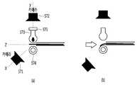
도 6는 본 발명의 일 실시 예에 따른 가이드 와이어 밴딩 장치의 구동부 구성을 보다 상세하게 나타내는 개념도이다. 6 is a conceptual diagram showing in detail the configuration of the drive unit of the guide wire bending device according to an embodiment of the present invention.
도 6에 도시된 바와 같이, 본 발명의 일 실시 예에 따른 가이드 와이어 밴딩 장치(200)는 가이드 와이어(A)를 환자(B), 구체적으로 환자의 혈관에 삽입하기 위해 적절하게 밴딩한다.As illustrated in FIG. 6, the guide
이때, 가이드 와이어(A)는 구동부(270)에 의해 밴딩 될 수 있는데, 구체적으로, 회전 구동부 (271)에 의해 적절한 방향으로 회전할 수 있으며, 전후진 구동부(272)에 의해 병진 운동을 할 수 있으며, 각도 조절부(273)에 의해 밴딩 각도(bending angle) 및 곡률 반경(radius of curvature)가 조절될 수 있다. 여기에서 말하는 벤딩 각도 및 곡률 반경은 도 7에 도시된 바와 같이 정의될 수 있다.At this time, the guide wire (A) can be bent by the
도 6에 도시된 바와 같이, 각도 조절부(273)은 환자(B)에게 삽입되기 직전 위치에 제공되는 것이 바람직할 수 있으나, 다른 위치에 제공될 수도 있다.As shown in FIG. 6, the
도 8은 각도 조절부에 의해 가이드 와이어 팁이 밴딩되는 과정을 나타내는 개념도이다. 도 8(a)는 가이드 와이어 팁이 각도 조절부(273)에 의해 밴딩 되기 전, 도 8(b)는 가이드 와이어 팁이 각도 조절부(273)에 의해 밴딩 된 후를 나타낸다.8 is a conceptual diagram illustrating a process of bending the guide wire tip by the angle adjuster. FIG. 8 (a) shows before the guide wire tip is bent by the
도 8에 도시된 바와 같이, 각도 조절부(273)는 제1 카메라(571), 제2 카메라(572), 가이드 와이어 누름 막대(573) 및 가이드 와이어 지지 롤러(574)를 포함한다. 또한, 각도 조절부(273)는 힘/압력 센서(575)를 추가적으로 포함할 수도 있다.As shown in FIG. 8, the
제1 카메라(571) 및 제2 카메라(572)는 팁 부분의 형상을 모니터링한다. 구체적으로 각도 조절부(273)에 의해 벤딩된 가이드 와이어 팁의 형상을 모니터링한다. 모니터링된 팁의 형상은 제어부(280)로 전달되어 피드백 과정에 활용된다.The
도 8에서는 2대의 카메라를 도시하고 있으나, 카메라 대수는 2대로 제한되지 않는다. 다만, 본 발명의 바람직한 실시 예에서 팁 부분의 3차원 형상을 측정하기 위해 2대의 카메라가 서로 직교하도록 제공될 수 있다.8 shows two cameras, the number of cameras is not limited to two. However, in the preferred embodiment of the present invention, two cameras may be provided to be orthogonal to each other to measure the three-dimensional shape of the tip portion.
가이드 와이어 누름 막대(573)는 가이드 와이어를 눌러 가이드 와이어 팁의 형상을 변형시킨다. 구체적으로 가이드 와이어 누름 막대(573)는 가이드 와이어 막대를 누르고, 압력을 받은 가이드 와이어는 가이드 와이어 지지 롤러(574)의 형상에 따라 형상이 변형된다.Guide
이때, 가이드 와이어 누름 막대(573)은 힘/압력 센서(575)를 추가적으로 포함할 수 있으며, 힘/압력 센서(575)는 가이드 와이어에 전달되는 압력을 모니터링한다. 모니터링된 결과는 제어부(280)로 전달되어 가이드 와이어의 영구적 변형 및 파손을 방지하게 한다.In this case, the guide
가이드 와이어 지지 롤러(574)는 도 9에서 보다 상세하게 설명한다.Guide
도 9는 본 발명의 일 실시 예에 따른 가이드 와이어 지지 롤러를 나타낸다.Figure 9 shows a guide wire support roller according to an embodiment of the present invention.
도 9에 도시된 바와 같이, 가이드 와이어 지지 롤러(574)는 복수의 곡률 변경부(541 내지 548), 회전 축(560) 및 회전 판(561)을 포함한다. 도 9에는 8개의 곡률 변경부가 개시되어 있으나, 곡률 변경부의 개수는 일 예시에 불과하다.As shown in FIG. 9, the guide
복수의 곡률 변경부(541 ?? 548)은 가이드 와이어 팁에 다양한 밴딩 각도 및 곡률을 제공한다. 혈관의 형태 및 목표 지점의 위치에 따라 다향한 밴딩 각도 및 곡률이 요구될 수 있다. 따라서, 본 발명의 일 실시 예에 따른 가이드 와이어 밴딩 장치는 복수의 곡률 및 밴딩 각도를 제공할 수 있는 곡률 변경부를 포함할 수 있다.The plurality of
회전 축(560) 및 회전 판(561)은 제어부(280)로부터 전달 받은 최적의 밴딩 각도 및 곡률에 따라 적절한 곡률 변경부를 선택한다. 구체적으로, 회전 축(560) 및 회전 판(561)는 선택된 곡률 변경부를 가이드 와이어 누름 막대와 맞닿을 수 있는 위치로 이동 시킨다.The
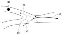
도 10a 내지 도 10c는 피드백을 이용하여 가이드 와이어를 삽입하는 방법을 설명하기 위한 도면이다. 10A to 10C are diagrams for describing a method of inserting a guide wire using feedback.
도 10a를 참조하면, 가이드 와이어 밴딩 장치(200)의 제어부(280)는 혈관과 가이드 와이어에 대한 정보를 모두 포함하는 영상 정보를 획득할 수 있다. 또한, 가이드 와이어 밴딩 장치(200)의 제어부(280)는 가이드 와이어(620)가 삽입되어야 하는 목표 지점(610)에 대한 정보를 얻을 수 있다. 또한, 가이드 와이어 밴딩 장치(200)의 제어부(280)는 목표 혈관 벡터(630)의 방향을 획득할 수 있다. 또한, 가이드 와이어 밴딩 장치(200)의 제어부(280)는 가이드 와이어 벡터(640)의 방향을 측정할 수 있다. 그리고 가이드 와이어 밴딩 장치(200)의 제어부(280)는 가이드 와이어 벡터(640)의 방향과 목표 혈관 벡터(630)의 방향 사이의 각도(650)을 획득할 수 있다.Referring to FIG. 10A, the
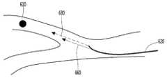
도 10b를 참조하면, 가이드 와이어가 회전함에 따라서, 혈관내의 가이드 와이어 벡터(660)의 방향도 바뀌게 된다. 가이드 와이어 밴딩 장치(200)의 제어부(280)는 이와 같이 가이드 와이어 벡터(660)의 방향이 변하는 것을 실시간으로 확인할 수 있다.Referring to FIG. 10B, as the guide wire rotates, the direction of the
회전 피드백을 제공할 때, 가이드 와이어 밴딩 장치(200)의 제어부(280)는 가이드 와이어 벡터(640)의 방향과 목표 혈관 벡터(630)의 방향 사이의 각도(650)가 미리 정해진 각도 이하로 작아질 때까지, 햅틱부(260)를 이용하여 진동을 발생할 수 있다.When providing the rotational feedback, the
가이드 와이어 밴딩 장치(200)의 제어부(280)는 가이드 와이어 벡터(640)의 방향과 목표 혈관 벡터(630)의 방향 사이의 각도(650)의 크기에 따라서, 햅틱부(260)에서 발생하는 진동의 크기를 변경할 수 있다. 예를 들어, 가이드 와이어 벡터(640)의 방향과 목표 혈관 벡터(630)의 방향 사이의 각도(650)의 크기가 커지면 그에 따라서 진동의 크기를 증가 시킬 수 있다.The
또한, 가이드 와이어 밴딩 장치(200)의 제어부(280)는 가이드 와이어 벡터(640)의 방향과 목표 혈관 벡터(630)의 방향 사이의 각도(650)의 크기에 따라서, 햅틱부(260)에서 발생하는 진동의 패턴을 변경할 수 있다.In addition, the
따라서, 수술을 집도하는 의사는 햅틱부(260)에서 발생되는 진동을 인식하여 가이드 와이어 벡터(640)의 방향과 목표 혈관 벡터(630)의 방향 사이의 각도(650)의 크기를 판단할 수 있어 보다 용이하게 가이드 와이어를 혈관내의 목표 지점까지 삽입할 수 있는 효과를 얻을 수 있다.Therefore, the surgeon performing the surgery may determine the magnitude of the
또한 도 10c를 참조하면, 분기점이 복수인 경우 가이드 와이어 밴딩 장치(200)의 제어부(280)는 각각의 분기점에서 상술한 동작을 수행하여 가이드 와이어가 원하는 혈관으로 삽입될 수 있도록 할 수 있다.In addition, referring to FIG. 10C, when there are a plurality of branch points, the
도 11은 자동으로 가이드 와이어를 삽입하는 방법을 설명하기 위한 순서도 이다. 11 is a flowchart illustrating a method of automatically inserting a guide wire.
자동으로 가이드 와이어를 삽입하는 방법은 혈관 조영 영상을 촬영하는 단계(S210), 실시간 X-ray 영상을 촬영하는 단계(S220), 정합된 X-ray영상을 생성하는 단계(S230), 목표 혈관 벡터를 측정하는 단계(S240), 가이드 와이어 팁을 밴딩하는 단계(S250), 가이드 와이어 벡터와 목표 혈관 벡터와 이루는 각도를 계산하는 단계(S260), 가이드 와이어를 회전 시키는 단계(S270), 가이드 와이어와 목표 지점의 거리를 측정하는 단계(S280), 목표 지점까지 가이드 와이어를 전진시키는 단계(S290) 등을 포함할 수 있다.The method for automatically inserting the guide wire includes capturing an angiography image (S210), capturing a real-time X-ray image (S220), generating a matched X-ray image (S230), and a target blood vessel vector. Measuring step (S240), the step of bending the guide wire tip (S250), the step of calculating the angle between the guide wire vector and the target vessel vector (S260), rotating the guide wire (S270), the guide wire and It may include the step of measuring the distance of the target point (S280), the step of advancing the guide wire to the target point (S290) and the like.
혈관 조영 영상을 촬영하는 단계(S210), 실시간 X-ray 영상을 촬영하는 단계(S220), 정합된 X-ray영상을 생성하는 단계(S230)는 도 4에서 설명한 혈관 조영 영상을 촬영하는 단계(S110), 실시간 X-ray 영상을 촬영하는 단계(S120), 정합된 X-ray영상을 생성하는 단계(S130)와 유사하여 구체적인 설명은 생략한다.Taking the angiography image (S210), taking a real-time X-ray image (S220), and generating a matched X-ray image (S230) may include taking the angiography image described with reference to FIG. S110), similar to the step of taking a real-time X-ray image (S120) and the step of generating a matched X-ray image (S130), a detailed description thereof will be omitted.
목표 혈관 벡터를 측정하는 단계(S240)에서 가이드 와이어 밴딩 장치(200)의 제어부(280)는 가이드 와이어가 삽입될 목표 지점이 결정되면, 혈관의 분기점에서 가이드 와이어와 가이드 와이어가 삽입될 목표 지점 사이의 방향 벡터를 측정할 수 있다.In operation S240, when the target point to which the guide wire is to be inserted is determined, the
가이드 와이어 팁을 밴딩하는 단계(S250)는 도 4에서 설명한 가이드 와이어 팁 밴딩 단계(S130)와 동일한바, 여기에서는 설명을 생략한다.The step S250 of bending the guide wire tip is the same as the guide wire tip bending step S130 described with reference to FIG. 4, and thus description thereof is omitted.
다음으로, 가이드 와이어 벡터와 목표 혈관 벡터와 이루는 각도를 계산하는 단계(S260)에서 가이드 와이어 밴딩 장치(200)의 제어부(280)는 가이드 와이어 벡터와 목표 혈관 벡터와 이루는 각도를 계산할 수 있다.Next, in step S260 of calculating an angle between the guide wire vector and the target blood vessel vector, the
다음으로, 가이드 와이어를 회전 시키는 단계(S270)에서, 가이드 와이어 밴딩 장치(200)의 제어부(280)는 가이드 와이어 벡터와 가이드 와이어가 삽입될 목표 지점 사이의 방향 벡터의 사이의 각도가 최소가 되게 가이드 와이어를 회전 시킬 수 있다.Next, in the step (S270) of rotating the guide wire, the
목표 지점의 거리를 측정하는 단계(S280)에서, 가이드 와이어 밴딩 장치(200)의 제어부(280)는 가이드 와이어와 목표 지짐간의 거리를 측정한다. 구체적으로, 제어부(280)는 정합된 X-ray 영상에 기초하여 가이드 와이어와 목표 지점간의 거리를 측정할 수 있다.In step (S280) of measuring the distance of the target point, the
목표 지점까지 가이드 와이어를 전진시키는 단계(S290)에서, 가이드 와이어 밴딩 장치(200)의 제어부(280)는 측정된 목표 지점까지의 거리에 기초하여 가이드 와이어를 전진 시킨다.In the step S290 of advancing the guide wire to the target point, the
상술한 바와 같이 본 발명의 일 실시예에 따르면, 수술을 집도하는 의사는 수동으로 가이드 와이어를 조절할 필요 없이, 가이드 와이어 밴딩 장치(200)통해 가이드 와이어의 상태를 파악하여, 자동으로 가이드 와이어가 목표 지점까지 삽입될 수 있도록 제어 할 수 있어 보다 용이하게 가이드 와이어를 목표 지점까지 삽입 할 수 있는 효과를 얻을 수 있다.As described above, according to an embodiment of the present invention, the doctor instructing the surgery does not need to manually adjust the guide wire, and grasps the state of the guide wire through the guide
전술한 본 발명은, 프로그램이 기록된 매체에 컴퓨터가 읽을 수 있는 코드로서 구현하는 것이 가능하다. 컴퓨터가 읽을 수 있는 매체는, 컴퓨터 시스템에 의하여 읽혀질 수 있는 데이터가 저장되는 모든 종류의 기록장치를 포함한다. 컴퓨터가 읽을 수 있는 매체의 예로는, HDD(Hard Disk Drive), SSD(Solid State Disk), SDD(Silicon Disk Drive), ROM, RAM, CD-ROM, 자기 테이프, 플로피 디스크, 광 데이터 저장 장치 등이 있으며, 또한 캐리어 웨이브(예를 들어, 인터넷을 통한 전송)의 형태로 구현되는 것도 포함한다. 또한, 상기 컴퓨터는 단말기의 제어부(180)를 포함할 수도 있다. 따라서, 상기의 상세한 설명은 모든 면에서 제한적으로 해석되어서는 아니되고 예시적인 것으로 고려되어야 한다. 본 발명의 범위는 첨부된 청구항의 합리적 해석에 의해 결정되어야 하고, 본 발명의 등가적 범위 내에서의 모든 변경은 본 발명의 범위에 포함된다.The present invention described above can be embodied as computer readable codes on a medium in which a program is recorded. The computer-readable medium includes all kinds of recording devices in which data that can be read by a computer system is stored. Examples of computer-readable media include hard disk drives (HDDs), solid state disks (SSDs), silicon disk drives (SDDs), ROMs, RAMs, CD-ROMs, magnetic tapes, floppy disks, optical data storage devices, and the like. This also includes implementations in the form of carrier waves (eg, transmission over the Internet). In addition, the computer may include the controller 180 of the terminal. Accordingly, the above detailed description should not be construed as limiting in all aspects and should be considered as illustrative. The scope of the invention should be determined by reasonable interpretation of the appended claims, and all changes within the equivalent scope of the invention are included in the scope of the invention.
200: 가이드 와이어 밴딩 장치
210: 혈관 조영 영상 촬영부220: X-ray촬영부
230: 통신부240: 메모리
250: 가이드 와이어 인식부260: 햅틱부
270: 구동부280: 제어부200: guide wire banding device
210: angiography imaging unit 220: X-ray imaging unit
230: communication unit 240: memory
250: guide wire recognition unit 260: haptic unit
270: drive unit 280: control unit
Claims (7)
Translated fromKorean신체 내의 상기 혈관 및 상기 가이드 와이어를 촬영하는 촬영부;
상기 촬영부에서 촬영된 영상에 기초하여 가이드 와이어 팁의 밴딩 각도 및 곡률을 계산하는 제어부; 및
상기 제어부가 계산한 밴딩 각도 및 곡률에 따라 가이드 와이어 팁의 형상을 변형시키고 각도 조절부를 포함하는 구동부를 포함하고,
상기 각도 조절부는
상기 제어부가 계산한 밴딩 각도 및 곡률에 대응하는 가이드 와이어 지지 롤러, 가이드 와이어에 압력을 가하여 상기 가이드 와이어 지지 롤러의 형상에 따라 각도를 조절하는 가이드 와이어 누름 막대를 포함하고,
상기 가이드 와이어는, 상기 가이드 와이어 지지 롤러의 형상에 따라 형상이 변형되는
가이드 와이어 밴딩 장치.In the guide wire banding device for inserting the guide wire into the vessel,
A photographing unit which photographs the blood vessel and the guide wire in the body;
A controller configured to calculate a bending angle and a curvature of the guide wire tip based on the image photographed by the photographing unit; And
It includes a drive unit for modifying the shape of the guide wire tip according to the bending angle and curvature calculated by the control unit and including an angle adjustment unit,
The angle adjustment unit
A guide wire holding roller corresponding to the bending angle and curvature calculated by the controller, and a guide wire pressing bar for adjusting an angle according to the shape of the guide wire supporting roller by applying pressure to the guide wire,
The guide wire is deformed in shape according to the shape of the guide wire support roller.
Guide wire banding device.
상기 구동부는 가이드 와이어를 회전시키는 회전 구동부 및 가이드 와이어를 전후진 병진시키는 전후진 구동부를 포함하고,
상기 각도 조절부는, 가이드 와이어의 밴딩 각도를 조절하는
가이드 와이어 밴딩 장치.According to claim 1,
The driving unit includes a rotation driving unit for rotating the guide wire and the forward and backward driving unit for translating the guide wire forward and backward,
The angle adjusting unit, for adjusting the bending angle of the guide wire
Guide wire banding device.
상기 각도 조절부는
상기 가이드 와이어 누름 막대가 가이드 와이어에 가하는 압력을 모니터링하는 힘/압력 센서를 더 포함하는
가이드 와이어 밴딩 장치.According to claim 1,
The angle adjustment unit
Further comprising a force / pressure sensor for monitoring the pressure applied by the guide wire push bar to the guide wire
Guide wire banding device.
상기 각도 조절부는
상기 가이드 와이어 누름 막대 및 가이드 와이어 지지 롤러에 의해 변형된 가이드 와이어의 밴딩 각도 및 곡률을 모니터링하기 위한 카메라를 더 포함하는
가이드 와이어 밴딩 장치.According to claim 1,
The angle adjustment unit
The camera further includes a camera for monitoring the bending angle and curvature of the guide wire deformed by the guide wire push bar and the guide wire support roller.
Guide wire banding device.
상기 제어부는
상기 카메라에 의해 모니터링된 변형 결과와 상기 촬영부로부터 획득한 혈관 영상을 비교하고, 추가 변형 여부를 결정하는
가이드 와이어 밴딩 장치.The method of claim 5,
The control unit
Comparing the result of the deformation monitored by the camera and the blood vessel image obtained from the photographing unit to determine whether to further modify
Guide wire banding device.
상기 가이드 와이어 지지 롤러는
혈관의 다양한 형상에 대응할 수 있는 복수의 곡률 변경부를 포함하는
가이드 와이어 밴딩 장치.According to claim 1,
The guide wire support roller is
It includes a plurality of curvature changer that can correspond to various shapes of the blood vessel
Guide wire banding device.
Priority Applications (1)
| Application Number | Priority Date | Filing Date | Title |
|---|---|---|---|
| KR1020170093023AKR102013793B1 (en) | 2017-07-21 | 2017-07-21 | a guide wire bending device and control method thereof |
Applications Claiming Priority (1)
| Application Number | Priority Date | Filing Date | Title |
|---|---|---|---|
| KR1020170093023AKR102013793B1 (en) | 2017-07-21 | 2017-07-21 | a guide wire bending device and control method thereof |
Publications (2)
| Publication Number | Publication Date |
|---|---|
| KR20190010347A KR20190010347A (en) | 2019-01-30 |
| KR102013793B1true KR102013793B1 (en) | 2019-08-23 |
Family
ID=65277250
Family Applications (1)
| Application Number | Title | Priority Date | Filing Date |
|---|---|---|---|
| KR1020170093023AExpired - Fee RelatedKR102013793B1 (en) | 2017-07-21 | 2017-07-21 | a guide wire bending device and control method thereof |
Country Status (1)
| Country | Link |
|---|---|
| KR (1) | KR102013793B1 (en) |
Families Citing this family (5)
| Publication number | Priority date | Publication date | Assignee | Title |
|---|---|---|---|---|
| CN110496296B (en)* | 2019-08-06 | 2025-03-04 | 高杨 | Wide-angle controllable and directional interventional guidewire |
| KR102563710B1 (en)* | 2021-01-28 | 2023-08-04 | 이화여자대학교 산학협력단 | Mandrel wire shaping system and method for coil embolization |
| KR102806460B1 (en)* | 2022-06-29 | 2025-05-16 | 재단법인 아산사회복지재단 | Method and device to decide shape of guidewire tip |
| KR102806459B1 (en)* | 2022-08-10 | 2025-05-16 | 재단법인 아산사회복지재단 | Method and device to decide shape of guidewire tip |
| KR20250046637A (en)* | 2023-09-27 | 2025-04-03 | (주)엘엔로보틱스 | Treatment tool control device |
Citations (3)
| Publication number | Priority date | Publication date | Assignee | Title |
|---|---|---|---|---|
| JP2008534109A (en)* | 2005-03-31 | 2008-08-28 | パイエオン インコーポレイテッド | Apparatus and method for positioning a device within a tubular organ |
| JP2009285180A (en) | 2008-05-29 | 2009-12-10 | Ntn Corp | Operation support device for linear body |
| JP2010094235A (en)* | 2008-10-15 | 2010-04-30 | Nagoya Institute Of Technology | Insertion device |
- 2017
- 2017-07-21KRKR1020170093023Apatent/KR102013793B1/ennot_activeExpired - Fee Related
Patent Citations (3)
| Publication number | Priority date | Publication date | Assignee | Title |
|---|---|---|---|---|
| JP2008534109A (en)* | 2005-03-31 | 2008-08-28 | パイエオン インコーポレイテッド | Apparatus and method for positioning a device within a tubular organ |
| JP2009285180A (en) | 2008-05-29 | 2009-12-10 | Ntn Corp | Operation support device for linear body |
| JP2010094235A (en)* | 2008-10-15 | 2010-04-30 | Nagoya Institute Of Technology | Insertion device |
Also Published As
| Publication number | Publication date |
|---|---|
| KR20190010347A (en) | 2019-01-30 |
Similar Documents
| Publication | Publication Date | Title |
|---|---|---|
| KR102013793B1 (en) | a guide wire bending device and control method thereof | |
| US11813030B2 (en) | Robotic navigation of robotic surgical systems | |
| JP7129683B2 (en) | Insertion device positioning guidance system and method | |
| JP5285270B2 (en) | Automatic guide wire operation system | |
| JP5546850B2 (en) | X-ray diagnostic equipment | |
| JP5269376B2 (en) | Image display apparatus and X-ray diagnostic treatment apparatus | |
| JP7085093B2 (en) | Insertion device Positioning guidance system and method | |
| US10271910B2 (en) | Robotic catheter system with FFR integration | |
| EP3389759B1 (en) | System and method for controlling x-ray frame rate of an imaging system | |
| JP2022000246A (en) | Insertion device positioning guide system and method | |
| KR102365859B1 (en) | Repositionable Remote Control Medical System | |
| CN103654817B (en) | Apparatus and method for positioning medical supply | |
| KR20230027240A (en) | Control Scheme Calibration for Medical Instruments | |
| JP2020534094A (en) | Surgical instrument-mounted display system | |
| CN109009349A (en) | A kind of robot puncturing control method and device | |
| CN112638305A (en) | System and method for determining elongated tool trajectory | |
| CN109009348A (en) | A kind of robot puncturing system | |
| KR101916915B1 (en) | Apparatus and method of insertion of a guide-wire | |
| EP3656305A1 (en) | Medical apparatus and method for operating the medical apparatus | |
| CN115281802A (en) | Control method, equipment and system of puncture device | |
| JP2023515420A (en) | Methods and systems for catheter target locking | |
| JP2020000866A (en) | Producing guidewire comprising position sensor | |
| EP4011315A1 (en) | Guidance system with claviculae position sensors | |
| JP7726488B2 (en) | Determining the roll angle of the distal end of a deflectable or non-deflectable invasive medical device | |
| KR200487320Y1 (en) | Operating medical navigation system with the tiltable head part |
Legal Events
| Date | Code | Title | Description |
|---|---|---|---|
| A201 | Request for examination | ||
| PA0109 | Patent application | St.27 status event code:A-0-1-A10-A12-nap-PA0109 | |
| PA0201 | Request for examination | St.27 status event code:A-1-2-D10-D11-exm-PA0201 | |
| D13-X000 | Search requested | St.27 status event code:A-1-2-D10-D13-srh-X000 | |
| D14-X000 | Search report completed | St.27 status event code:A-1-2-D10-D14-srh-X000 | |
| E902 | Notification of reason for refusal | ||
| PE0902 | Notice of grounds for rejection | St.27 status event code:A-1-2-D10-D21-exm-PE0902 | |
| PG1501 | Laying open of application | St.27 status event code:A-1-1-Q10-Q12-nap-PG1501 | |
| E13-X000 | Pre-grant limitation requested | St.27 status event code:A-2-3-E10-E13-lim-X000 | |
| P11-X000 | Amendment of application requested | St.27 status event code:A-2-2-P10-P11-nap-X000 | |
| P13-X000 | Application amended | St.27 status event code:A-2-2-P10-P13-nap-X000 | |
| E701 | Decision to grant or registration of patent right | ||
| PE0701 | Decision of registration | St.27 status event code:A-1-2-D10-D22-exm-PE0701 | |
| GRNT | Written decision to grant | ||
| PR0701 | Registration of establishment | St.27 status event code:A-2-4-F10-F11-exm-PR0701 | |
| PR1002 | Payment of registration fee | St.27 status event code:A-2-2-U10-U11-oth-PR1002 Fee payment year number:1 | |
| PG1601 | Publication of registration | St.27 status event code:A-4-4-Q10-Q13-nap-PG1601 | |
| PR1001 | Payment of annual fee | St.27 status event code:A-4-4-U10-U11-oth-PR1001 Fee payment year number:4 | |
| PC1903 | Unpaid annual fee | St.27 status event code:A-4-4-U10-U13-oth-PC1903 Not in force date:20230820 Payment event data comment text:Termination Category : DEFAULT_OF_REGISTRATION_FEE | |
| PC1903 | Unpaid annual fee | St.27 status event code:N-4-6-H10-H13-oth-PC1903 Ip right cessation event data comment text:Termination Category : DEFAULT_OF_REGISTRATION_FEE Not in force date:20230820 | |
| R18-X000 | Changes to party contact information recorded | St.27 status event code:A-5-5-R10-R18-oth-X000 | |
| R18-X000 | Changes to party contact information recorded | St.27 status event code:A-5-5-R10-R18-oth-X000 |