KR102012972B1 - Apparatus for transmitting and receiving wireless power - Google Patents
Apparatus for transmitting and receiving wireless powerDownload PDFInfo
- Publication number
- KR102012972B1 KR102012972B1KR1020130160520AKR20130160520AKR102012972B1KR 102012972 B1KR102012972 B1KR 102012972B1KR 1020130160520 AKR1020130160520 AKR 1020130160520AKR 20130160520 AKR20130160520 AKR 20130160520AKR 102012972 B1KR102012972 B1KR 102012972B1
- Authority
- KR
- South Korea
- Prior art keywords
- power
- module
- switching
- receiving
- unit
- Prior art date
- Legal status (The legal status is an assumption and is not a legal conclusion. Google has not performed a legal analysis and makes no representation as to the accuracy of the status listed.)
- Active
Links
Images


Classifications
- H—ELECTRICITY
- H04—ELECTRIC COMMUNICATION TECHNIQUE
- H04W—WIRELESS COMMUNICATION NETWORKS
- H04W4/00—Services specially adapted for wireless communication networks; Facilities therefor
- H04W4/80—Services using short range communication, e.g. near-field communication [NFC], radio-frequency identification [RFID] or low energy communication
- H—ELECTRICITY
- H02—GENERATION; CONVERSION OR DISTRIBUTION OF ELECTRIC POWER
- H02J—CIRCUIT ARRANGEMENTS OR SYSTEMS FOR SUPPLYING OR DISTRIBUTING ELECTRIC POWER; SYSTEMS FOR STORING ELECTRIC ENERGY
- H02J50/00—Circuit arrangements or systems for wireless supply or distribution of electric power
- H02J50/10—Circuit arrangements or systems for wireless supply or distribution of electric power using inductive coupling
- H02J50/12—Circuit arrangements or systems for wireless supply or distribution of electric power using inductive coupling of the resonant type
- H—ELECTRICITY
- H02—GENERATION; CONVERSION OR DISTRIBUTION OF ELECTRIC POWER
- H02J—CIRCUIT ARRANGEMENTS OR SYSTEMS FOR SUPPLYING OR DISTRIBUTING ELECTRIC POWER; SYSTEMS FOR STORING ELECTRIC ENERGY
- H02J50/00—Circuit arrangements or systems for wireless supply or distribution of electric power
- H02J50/80—Circuit arrangements or systems for wireless supply or distribution of electric power involving the exchange of data, concerning supply or distribution of electric power, between transmitting devices and receiving devices
- H—ELECTRICITY
- H04—ELECTRIC COMMUNICATION TECHNIQUE
- H04B—TRANSMISSION
- H04B5/00—Near-field transmission systems, e.g. inductive or capacitive transmission systems
- H04B5/70—Near-field transmission systems, e.g. inductive or capacitive transmission systems specially adapted for specific purposes
- H04B5/79—Near-field transmission systems, e.g. inductive or capacitive transmission systems specially adapted for specific purposes for data transfer in combination with power transfer
- H—ELECTRICITY
- H02—GENERATION; CONVERSION OR DISTRIBUTION OF ELECTRIC POWER
- H02J—CIRCUIT ARRANGEMENTS OR SYSTEMS FOR SUPPLYING OR DISTRIBUTING ELECTRIC POWER; SYSTEMS FOR STORING ELECTRIC ENERGY
- H02J7/00—Circuit arrangements for charging or depolarising batteries or for supplying loads from batteries
- H02J7/00032—Circuit arrangements for charging or depolarising batteries or for supplying loads from batteries characterised by data exchange
- H02J7/00034—Charger exchanging data with an electronic device, i.e. telephone, whose internal battery is under charge
Landscapes
- Engineering & Computer Science (AREA)
- Computer Networks & Wireless Communication (AREA)
- Power Engineering (AREA)
- Signal Processing (AREA)
- Charge And Discharge Circuits For Batteries Or The Like (AREA)
Abstract
Translated fromKorean
Description
Translated fromKorean본 발명은 무선 전력 송수신 장치에 관한 것이다.
The present invention relates to a wireless power transmission and reception apparatus.
최근 휴대폰 및 개인 휴대폰 전자제품은 울트라 슬림(Ultra-slim)을 유지하면서, 많은 기능이 추가되어 시장에 출시되고 있다. 이러한 개인 휴대용 전자 제품이 작동하기 위해서는 배터리와 같은 전원이 필수적으로 필요하다. 따라서, 개인 휴대용 전자 제품은 필수적으로 배터리에 대한 사용 시간, 충전 등에 관한 관심이 집중되고 있다.Recently, cell phones and personal cell phone electronics have been introduced to the market with many additional features while maintaining ultra-slim. In order for these personal portable electronics to work, a power source such as a battery is essential. Accordingly, personal portable electronic products have been focused on the use time, charging and the like for the battery.
한편, 사용자로 하여금 배터리 충전에 관한 자유도를 부여하기 위해, 최근 핸드폰 제조업체는 무선 충전 기술 도입을 추진하고 있다. 이때, 무선 충전 방식은 전파(Microwave)를 이용한 전파 수신형 방식, 자기장을 이용한 자기 유도 방식 또는 자기장과 전기장의 에너지 전환에 의한 자기 공진 방식 등이 대표적이다.Meanwhile, in order to give a user freedom in charging a battery, a mobile phone manufacturer has recently introduced wireless charging technology. In this case, the wireless charging method is typically a radio wave reception type using a microwave, a magnetic induction method using a magnetic field, or a magnetic resonance method by switching energy between a magnetic field and an electric field.
여기서 전파 수신형 방식은 안테나를 통해 전파를 공기 중으로 방사함으로써 먼 거리까지 전력 전송 가능한 장점이 있으나, 공기 중에서 소모되는 방사 손실(Radiation loss)이 매우 커서 전력 전송의 효율성에 한계가 있다.Here, the radio wave reception method has an advantage that power can be transmitted over a long distance by radiating radio waves into the air through an antenna, but the radiation loss consumed in the air is very large, which limits the efficiency of power transmission.
자기 유도 방식과 자기 공진 방식의 경우 각각의 기술 표준 협회가 설립되어 있다. 상기 자기 유도 방식은 WPC(Wireless Power Consortium)라는 단체를 구성하여 표준과 호환성을 확립한 상용화를 진행 중에 있으며, 자기 공진 방식은 A4WP(Alliance for Wireless Power)라는 단체를 구성하여 표준과 호환성을 확립한 상용화를 진행 중에 있다. 이때, 자기 유도 방식의 경우 110KHz 내지 282KHz의 공진 주파수를 사용하고 있으며, 자기 공진 방식의 경우 6.78MHz 및 13.56MHz의 공진 주파수를 사용하고 있다.In the case of the magnetic induction method and the magnetic resonance method, respective technical standard associations are established. The magnetic induction method is in the process of commercialization by establishing an organization called WPC (Wireless Power Consortium) to establish compatibility with standards, and the magnetic resonance method by forming an organization called A4WP (Alliance for Wireless Power) to establish compatibility with standards. Commercialization is in progress. At this time, the magnetic induction method uses a resonant frequency of 110KHz to 282KHz, and the magnetic resonance method uses a resonant frequency of 6.78MHz and 13.56MHz.
한편, 상기 자기 공진 방식의 경우, 자기 공진에 의해 전력을 유도하기 때문에 송신기기와 수신기기간의 공간과 위치의 자유도를 높일 수 있다. 즉, 송신기기와 수신기기를 정확한 위치에서 접촉시키지 않아도 되므로, 사용자의 편이성을 높일 수 있으며, 복수의 수신기기를 동시에 충전하는 것이 가능하다.On the other hand, in the magnetic resonance method, since power is induced by magnetic resonance, it is possible to increase the degree of freedom of space and position of the transmitter and receiver periods. That is, since the transmitter and the receiver do not have to be contacted at the correct position, the user's convenience can be increased and the plurality of receivers can be charged simultaneously.
다만, 무선 전력 전송이 가능한 송신기기도 배터리가 소모됨에 따라, 다른 송신 기기로부터 전력 수신이 요구될 수 있다. 따라서, 하나의 장치에 무선으로 전력 송신 및 수신이 가능한 장치가 요구되고 있다. 동시에, 복수의 수신 기기와의 무선 통신을 수행하여 데이터를 송수신함으로써 다양한 서비스를 구현할 수 있는 장치가 필요하다.
However, a transmitter capable of wireless power transmission may also require power reception from another transmitting device as the battery is consumed. Therefore, there is a need for a device capable of wirelessly transmitting and receiving power in one device. At the same time, there is a need for an apparatus capable of implementing various services by transmitting and receiving data by performing wireless communication with a plurality of receiving devices.
하기의 선행기술문헌인 특허문헌 1은 양방향 무선 전력 송신에 관한 발명으로, 안테나에서 수신된 유도 전류를 DC 전력으로 정류하고, DC 전력에 응답하여 안테나에게 공진을 유도하도록 재구성 가능한 내용이 기재되어 있다. 다만, 본 발명과는 달리, 자기 공진 방식에서의 무선 전력 송수신 및 이를 제어하기 위해 사전에 설정된 무선 통신 방식을 이용하는 내용에 대해서는 기재되어 있지 않다.
Patent Document 1, which is the following prior art document, relates to a bidirectional wireless power transmission, and describes reconfigurable contents to rectify induced current received from an antenna into DC power and induce resonance to the antenna in response to DC power. . However, unlike the present invention, wireless power transmission and reception in a self-resonant method and a content using a preset wireless communication method for controlling the same are not described.
본 발명은 주변 기기와 사전에 설정된 방식을 통하여 무선 통신을 수행함과 동시에, 무선 전력 전송이 필요한지 여부를 판단하여, 필요한 주변 기기에 무선으로 전력을 전송해 줄 수 있으며, 또한, 외부로부터 무선 전력을 제공받을 수 있는 무선 전력 송수신 장치를 제안한다.
The present invention can perform wireless communication through a preset method with a peripheral device, determine whether wireless power transmission is necessary, and wirelessly transmit power to a required peripheral device. The present invention proposes a wireless power transceiver.
본 발명의 제1 기술적인 측면에 따른 무선 충전 송수신 장치는, 외부로부터 전력을 제공받아 배터리를 충전하는 송신 모듈; 상기 배터리의 전력을 상기 외부로 제공하는 수신 모듈; 상기 송신 모듈 및 상기 수신 모듈 중 하나가 선택되도록 스위칭 동작을 수행하는 스위칭부; 상기 외부와 블루투스 통신을 수행하며, 상기 스위칭부의 스위칭 동작을 제어하는 스위칭 제어부; 및 동작 모드 정보를 설정하여 상기 스위칭 제어부에 상기 동작 모드 정보를 제공하는 호스트 제어부; 를 포함하며, 상기 스위칭 제어부는, 상기 동작 모드에 따라 외부와 블루투스 통신을 이용하여 데이터를 송신 또는 수신할 수 있다.
In accordance with a first aspect of the present invention, there is provided a wireless charging / transmitting / receiving apparatus comprising: a transmitting module configured to charge a battery by receiving power from an external device; A receiving module providing power of the battery to the outside; A switching unit which performs a switching operation so that one of the transmitting module and the receiving module is selected; A switching controller which performs Bluetooth communication with the outside and controls a switching operation of the switching unit; And a host controller configured to provide operation mode information to the switching controller by setting operation mode information. Includes, the switching control unit, according to the operation mode may transmit or receive data using the Bluetooth communication with the outside.
또한, 외부로부터 자기 공진 방식을 이용하여 전력을 제공받거나 또는 외부로 전력을 제공하는 공진 코일부; 를 더 포함할 수 있다.In addition, the resonance coil unit for receiving power from the outside using a magnetic resonance method or providing power to the outside; It may further include.
또한, 상기 스위칭부와 상기 공진 코일부 사이에 위치하고, 상기 공진 코일부로부터 제공받은 전력의 임피던스를 조절하여 상기 수신 모듈에 제공하거나, 상기 송신 모듈로부터 제공받은 전력의 임피던스를 조절하여 상기 공진 코일부로 제공하는 매칭 회로부; 를 더 포함할 수 있다.In addition, it is located between the switching unit and the resonant coil unit, and adjusts the impedance of the power provided from the resonant coil unit to provide to the receiving module, or by adjusting the impedance of the power provided from the transmitting module to the resonant coil unit. A matching circuit unit to provide; It may further include.
또한, 상기 송신 모듈은 자기 공진 방식을 이용하여 외부로부터 전력을 제공받으며, 상기 수신 모듈은 자기 공진 방식을 이용하여 외부로 전력을 제공할 수 있다.In addition, the transmission module may receive power from the outside using a magnetic resonance method, and the reception module may provide power to the outside using a magnetic resonance method.
또한, 상기 동작 모드 정보는, 외부로부터 전력을 제공받아 상기 배터리를 충전하는 송신 모드 및 상기 배터리의 전력을 상기 외부로 제공하는 수신 모드를 포함할 수 있다.The operation mode information may include a transmission mode for receiving power from an external source and charging the battery, and a reception mode for providing power of the battery to the outside.
또한, 상기 스위칭 제어부는, 상기 호스트 제어부로부터 제공받은 상기 동작 모드 정보를 확인하고, 상기 동작 모드 정보에 따라 상기 스위칭부의 스위칭 동작을 제어하는 제어부; 및 상기 블루투스 통신을 이용하여 데이터를 송수신하는 블루투스 모듈; 을 포함할 수 있다.The switching controller may include: a controller configured to check the operation mode information provided from the host controller and to control a switching operation of the switching unit according to the operation mode information; And a Bluetooth module for transmitting and receiving data using the Bluetooth communication. It may include.
또한, 상기 블루투스 모듈은, 상기 수신 모드에서, 상기 블루투스 통신을 이용하여 상태 정보를 외부로 제공하고, 상기 송신 모드에서, 상기 블루투스 통신을 이용하여 외부의 상태 정보를 제공받을 수 있다.
The Bluetooth module may provide status information to the outside using the Bluetooth communication in the reception mode, and receive external status information using the Bluetooth communication in the transmission mode.
본 발명의 제2 기술적인 측면에 따른 무선 전력 송수신 장치는, 배터리를 포함하고, 동작 모드를 설정하고, 이에 따라 외부와 블루투스 통신을 이용하여 데이터를 송신 또는 수신하는 호스트부; 및 상기 동작 모드가 수신 모드라면 외부로부터 자기 공진 방식을 이용하여 전력을 제공받아 상기 배터리를 충전하고, 상기 동작 모드가 송신 모드라면, 상기 배터리 전력을 자기 공진 방식을 이용하여 상기 외부로 제공하는 무선 전력 송수신부; 를 포함할 수 있다.
In accordance with another aspect of the present invention, there is provided a wireless power transmission / reception apparatus comprising: a host unit including a battery, setting an operation mode, and transmitting or receiving data using Bluetooth communication with the outside; And charging the battery by receiving power from the outside using a self resonance method when the operation mode is a reception mode, and wirelessly providing the battery power to the outside using a self resonance method when the operation mode is a transmission mode. A power transceiver; It may include.
또한, 상기 무선 전력 송수신부는, 외부와 자기 공진 방식을 이용하여 상기 전력을 송수신하는 공진 코일부; 상기 수신 모드에서, 외부로부터 자기 공진 방식을 이용하여 상기 전력을 제공받는 수신 모듈; 상기 송신 모드에서, 자기 공진 방식을 이용하여 외부로 상기 전력을 제공하는 송신 모듈; 상기 수신 모듈 및 송신 모듈 중 하나가 선택되도록 스위칭 동작을 수행하는 스위칭부; 및 상기 동작 모드에 따라 상기 스위칭부의 스위칭 동작을 제어하는 스위칭 제어부; 를 포함할 수 있다.The wireless power transmitter / receiver may include: a resonant coil unit configured to transmit and receive the power by using a magnetic resonance method with an external device; In the receiving mode, the receiving module receives the power from the outside using a magnetic resonance method; A transmission module for providing the power to the outside using a magnetic resonance method in the transmission mode; A switching unit which performs a switching operation so that one of the receiving module and the transmitting module is selected; And a switching controller controlling the switching operation of the switching unit according to the operation mode. It may include.
또한, 제9항에 있어서, 상기 스위칭 제어부는, 외부와 블루투스 통신을 이용하여 데이터를 송수신하는 블루투스 모듈; 및 상기 동작 모드에 따라 상기 스위칭부의 스위칭 동작을 제어하며, 상기 동작 모드에 따라 상기 블루투스 모듈의 모드를 제어하는 제어부; 를 포함하고, 상기 제어부는, 상기 동작 모드가 송신 모드라면, 상기 블루투스 모듈을 마스터(master) 모드로 설정하고, 상기 동작 모드가 수신 모드라면, 상기 블루투스 모듈을 슬레이브(slave) 모드로 설정할 수 있다.The apparatus of claim 9, wherein the switching controller comprises: a Bluetooth module for transmitting and receiving data to and from the outside using Bluetooth communication; And a control unit controlling a switching operation of the switching unit according to the operation mode and controlling a mode of the Bluetooth module according to the operation mode. The controller may set the Bluetooth module to a master mode if the operation mode is a transmission mode, and set the Bluetooth module to a slave mode if the operation mode is a reception mode. .
또한, 상기 블루투스 모듈은, 상기 마스터 모드일 경우에, 외부로부터 블루투스 통신을 이용하여 상태 정보를 제공받으며, 상기 슬레이브 모드일 경우에, 상기 블루투스 통신을 이용하여 외부에 상태 정보를 제공할 수 있다.In addition, the Bluetooth module may receive status information from the outside using Bluetooth communication in the master mode, and provide status information to the outside using the Bluetooth communication in the slave mode.
또한, 상기 수신 모듈은, 상기 공진 코일부로부터 제공받은 전력을 정류하는 정류기; 및 상기 정류기로부터 제공된 전력을 출력 전압으로 변환하여 상기 배터리로 제공하는 컨버터부; 를 포함할 수 있다.In addition, the receiving module, the rectifier for rectifying the power provided from the resonant coil unit; And a converter unit converting the power provided from the rectifier into an output voltage and providing the same to the battery. It may include.
또한, 상기 송신 모듈은, 상기 배터리로부터 제공받은 전력을 증폭하는 증폭기; 를 포함할 수 있다.In addition, the transmission module, an amplifier for amplifying the power received from the battery; It may include.
또한, 상기 스위칭부와 상기 공진 코일부 사이에 위치하고, 상기 공진 코일부로부터 제공받은 전력의 임피던스를 조절하여 상기 수신 모듈에 제공하거나, 상기 송신 모듈로부터 제공받은 전력의 임피던스를 조절하여 상기 공진 코일부로 제공하는 매칭 회로부; 를 더 포함할 수 있다.In addition, it is located between the switching unit and the resonant coil unit, and adjusts the impedance of the power provided from the resonant coil unit to provide to the receiving module, or by adjusting the impedance of the power provided from the transmitting module to the resonant coil unit. Matching circuit unit to provide; It may further include.
또한, 상기 동작 모드는, 기본 모드가 수신 모드일 수 있다.In addition, in the operation mode, the basic mode may be a reception mode.
또한, 상기 호스트부는, 상기 배터리; 상기 배터리에 공급되는 전력을 제어하는 전력 관리 모듈; 및 상기 동작 모드를 설정하는 호스트 제어부; 를 포함할 수 있다.
In addition, the host unit, the battery; A power management module controlling the power supplied to the battery; And a host controller configured to set the operation mode. It may include.
본 발명은 무선 전력의 송수신이 가능하며, 주변 기기와의 무선 통신을 수행할 수 있도록 브리지(birdge) 기능도 포함함으로써, 다양한 서비스를 사용자에게 제공할 수 있으며, 사용자 편의성을 증대시킬 수 있다.
The present invention can transmit and receive wireless power, and also includes a bridge function to perform wireless communication with peripheral devices, thereby providing various services to the user and increasing user convenience.
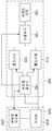
도1은 본 발명의 일 실시예에 따른 무선 전력 송수신 장치를 나타낸 블록도이다.
도2는 도1에 도시한 무선 전력 송수신 장치를 보다 상세하게 나타낸 블록도이다.
도3은 도1에 도시한 무선 전력 송수신 장치의 구성 중 송신 모듈의 일 실시예를 나타낸 블록도이다.
도4는 도1에 도시한 무선 전력 송수신 장치의 구성 중 수신 모듈의 일 실시예를 나타낸 블록도이다.
도5는 도1에 도시한 무선 전력 송수신 장치의 구성 중 스위칭 제어부의 일 실시예를 나타낸 블록도이다.
도6은 본 발명의 일 실시예에 따른 무선 전력 송수신 장치의 송신 모드시 동작을 나타내기 위한 도면이다.
도7은 본 발명의 일 실시예에 따른 무선 전력 송수신 장치의 수신 모드시 동작을 나타내기 위한 도면이다.
도8은 본 발명의 일 실시예에 따른 무선 전력 송수신 장치의 전체 동작 흐름을 나타낸 순서도이다.1 is a block diagram showing a wireless power transmission and reception apparatus according to an embodiment of the present invention.
FIG. 2 is a block diagram illustrating the wireless power transceiver of FIG. 1 in more detail.
FIG. 3 is a block diagram illustrating an embodiment of a transmission module of the wireless power transceiver of FIG. 1.
FIG. 4 is a block diagram illustrating an embodiment of a receiving module of the wireless power transceiver shown in FIG. 1.
FIG. 5 is a block diagram illustrating an exemplary embodiment of a switching controller of the wireless power transmitter and receiver shown in FIG. 1.
6 is a diagram illustrating an operation in a transmission mode of a wireless power transceiver according to an embodiment of the present invention.
7 is a diagram illustrating an operation in a reception mode of a wireless power transceiver according to an embodiment of the present invention.
8 is a flowchart illustrating the overall operation of the wireless power transceiver according to an embodiment of the present invention.
후술하는 본 발명에 대한 상세한 설명은, 본 발명이 실시될 수 있는 특정 실시예를 예시로서 도시하는 첨부 도면을 참조한다. 이들 실시예는 당업자가 본 발명을 실시할 수 있기에 충분하도록 상세히 설명된다. 본 발명의 다양한 실시예는 서로 다르지만 상호 배타적일 필요는 없음이 이해되어야 한다. 예를 들어, 여기에 기재되어 있는 특정 형상, 구조 및 특성은 일 실시예에 관련하여 본 발명의 정신 및 범위를 벗어나지 않으면서 다른 실시예로 구현될 수 있다. 또한, 각각의 개시된 실시예 내의 개별 구성요소의 위치 또는 배치는 본 발명의 정신 및 범위를 벗어나지 않으면서 변경될 수 있음이 이해되어야 한다. 따라서, 후술하는 상세한 설명은 한정적인 의미로서 취하려는 것이 아니며, 본 발명의 범위는, 적절하게 설명된다면, 그 청구항들이 주장하는 것과 균등한 모든 범위와 더불어 첨부된 청구항에 의해서만 한정된다. 도면에서 유사한 참조부호는 여러 측면에 걸쳐서 동일하거나 유사한 기능을 지칭한다.DETAILED DESCRIPTION The following detailed description of the invention refers to the accompanying drawings that show, by way of illustration, specific embodiments in which the invention may be practiced. These embodiments are described in sufficient detail to enable those skilled in the art to practice the invention. It should be understood that the various embodiments of the present invention are different but need not be mutually exclusive. For example, certain shapes, structures, and characteristics described herein may be embodied in other embodiments without departing from the spirit and scope of the invention with respect to one embodiment. In addition, it is to be understood that the location or arrangement of individual components within each disclosed embodiment may be changed without departing from the spirit and scope of the invention. The following detailed description, therefore, is not to be taken in a limiting sense, and the scope of the present invention, if properly described, is defined only by the appended claims, along with the full range of equivalents to which such claims are entitled. Like reference numerals in the drawings refer to the same or similar functions throughout the several aspects.
이하에서는, 본 발명이 속하는 기술분야에서 통상의 지식을 가진 자가 본 발명을 용이하게 실시할 수 있도록 하기 위하여, 본 발명의 실시예들에 관하여 첨부된 도면을 참조하여 상세히 설명하기로 한다.
DETAILED DESCRIPTION Hereinafter, exemplary embodiments of the present invention will be described in detail with reference to the accompanying drawings so that those skilled in the art may easily implement the present invention.
도1은 본 발명의 일 실시예에 따른 무선 전력 송수신 장치를 나타낸 블록도이다.1 is a block diagram showing a wireless power transmission and reception apparatus according to an embodiment of the present invention.
도1을 참조하면, 본 발명에 따른 무선 전력 송수신 장치는, 무선 전력 송수신부(100) 및 호스트부(200)를 포함할 수 있다.Referring to FIG. 1, the apparatus for transmitting and receiving wireless power according to the present invention may include a wireless power transmitting and receiving
상기 무선 전력 송수신부(100)는 송신 모듈(110), 수신 모듈(120), 스위칭부(130), 스위칭 제어부(140) 및 공진 코일부(150)를 포함할 수 있다.The
상기 호스트부(200)는 배터리(210) 및 호스트 제어부(220)를 포함할 수 있다.
The
먼저, 무선 전력 송수신부(100)의 각 구성에 대해 설명하기로 한다.First, each configuration of the
상기 송신 모듈(100)은 외부로부터 전력을 제공받아 상기 배터리(210)에 전력을 제공하여 충전할 수 있다. 이때, 전력을 제공해주는 외부는 본 발명에 따른 무선 전력 송수신 장치 주변의 송신 기기가 될 수 있으며, 상기 배터리(210)는 휴대용 무선 단말기 등에 사용되는 배터리일 수 있다.The
한편, 상기 송신 모듈(100)은 외부로부터 자기 공진 방식을 이용하여 배터리(210)를 충전할 수 있다. 이때, 자기 공진 방식은 A4WP(Alliance for Wireless Power) 표준을 사용할 수 있다.
On the other hand, the
상기 수신 모듈(200)은 상기 배터리(210)의 전력을 외부로 제공할 수 있다. 이때, 외부는 본 발명에 따른 무선 전력 송수신 장치 주변의 수신 기기가 될 수 있다.The receiving
상기 스위칭부(130)는 공진 코일부(150)와 상기 송신 및 수신 모듈(110, 120) 사이에 위치할 수 있다. 또한, 상기 송신 모듈(100) 및 수신 모듈(200) 중 하나가 선택되도록 스위칭 동작을 수행할 수 있다. 이때, 스위칭 동작을 위한 제어 신호는 상기 스위칭 제어부(140)로부터 제공받을 수 있다.The
즉, 스위칭부(130)는 상기 스위칭 제어부(140)로부터 제공받은 제어 신호에 따라, 스위칭 동작을 수행하여 동작 모드에 맞게 송신 모듈(110) 또는 수신 모듈(120) 중 하나가 선택되도록 할 수 있다.
That is, the
스위칭 제어부(140)는 상기 송신 및 수신 모듈(100, 200)과 각각 연결될 수 있으며, 상기 스위칭부(130)의 스위칭 동작을 제어할 수 있다. 이때, 스위칭 제어부(140)는 동작 모드에 따라 송신 모듈(110) 또는 수신 모듈(120) 중 하나가 선택되도록 제어 신호를 생성할 수 있다.The switching
상기 동작 모드는 상기 호스트부(200)의 구성 중 호스트 제어부(220)로부터 제공받을 수 있다. 즉, 호스트 제어부(220)로부터 제공받은 동작 모드 정보에 따라 상기 스위칭 제어부(140)는 현재 동작 모드가 송신 모드인지, 또는 수신 모드인지를 알 수 있다. 이때, 만약 동작 모드가 송신 모드라면, 송신 모듈(110)이 선택될 수 있도록 상기 스위칭부(130)의 스위칭 동작을 제어하며, 현재 동작 모드가 수신 모드라면, 수신 모듈(120)이 선택될 수 있도록 상기 스위칭부(130)의 스위칭 동작을 제어할 수 있다.The operation mode may be provided from the
또한, 상기 스위칭 제어부(140)는 외부와 블루투스 통신을 수행할 수 있다. 이를 통해, 자신의 상태 정보를 외부에 제공할 수 있으며, 외부 기기의 상태 정보를 제공받을 수도 있다. 이때, 상태 정보는 현재 블루투스 통신 상태, 배터리 정보 등이 될 수 있다. 이를 통해, 호스트 제어부(220)에서는 동작 모드를 설정할 수 있으며, 또한, 송신 및 수신이 가능한 상태인지를 판단할 수 있다.
In addition, the switching
한편, 상기 호스트 제어부(220)는 주변 기기와의 무선 통신 상태를 확인할 수 있으며, 현재 배터리(210)의 상태도 확인할 수 있다. 이에 따라, 본 발명에 따른 무선 전력 송수신 장치가 송신 모드로 동작해야하는지 또는 수신 모드로 동작해야하는지를 판단할 수 있다. 판단 이후에 동작 모드를 송신 모드 또는 수신 모드로 설정할 수 있으며, 스위칭 제어부(140)는 이에 따라 상기 스위칭부(130)의 스위칭 동작을 제어하여 상기 동작 모드에 따라 송신 모듈(110) 또는 수신 모듈(120)이 선택되도록 할 수 있다.
The
본 발명에 따른 무선 전력 송수신 장치는, 외부로부터 자기 공진 방식을 이용하여 전력을 제공받거나, 또는 외부로 전력을 자기 공진 방식으로 제공하는 공진 코일부(150)를 더 포함할 수 있다.The wireless power transmission / reception apparatus according to the present invention may further include a
즉, 무선 전력 송수신 장치의 동작 모드가 송신 모드라면, 배터리(210)에 충전되어 있는 전력을 송신 모듈(110) 및 공진 코일부(150)를 거쳐 외부 수신 기기에 제공할 수 있도록, 스위칭 제어부(140)에서 스위칭부(130)의 스위칭 동작을 제어할 수 있다.That is, when the operation mode of the wireless power transceiver is the transmission mode, the switching control unit may provide the power charged in the
또한, 무선 전력 송수신 장치의 동작 모드가 수신 모드라면, 외부 송신 기기로부터 제공하는 전력을 공진 코일부(150) 및 수신 모듈(120)을 거쳐 배터리(210)에 제공할 수 있도록, 스위칭 제어부(140)에서 스위칭부(130)의 스위칭 동작을 제어할 수 있다.
In addition, when the operation mode of the wireless power transceiver is the reception mode, the switching
도1에 도시한 무선 전력 송수신 장치를 도2를 참조하여 보다 상세하게 설명하기로 한다.The wireless power transceiver shown in FIG. 1 will be described in more detail with reference to FIG. 2.
도2는 도1에 도시한 무선 전력 송수신 장치를 보다 상세하게 나타낸 블록도이다.FIG. 2 is a block diagram illustrating the wireless power transceiver of FIG. 1 in more detail.
도2를 참조하면, 본 발명에 따른 무선 전력 송수신 장치는 공진 코일부(150)와 스위칭부(130) 사이에 위치하는 매칭 회로부(160)를 더 포함할 수 있다. 상기 매칭 회로부(160)는 수신 모드에서 공진 코일부(150)로부터 제공받은 전력의 임피던스를 조절하여 상기 수신 모듈(120)에 제공할 수 있다. 또한, 상기 매칭 회로부(160)는 송신 모드에서 송신 모듈(110)로부터 제공받은 전력의 임피던스를 조절하여 공진 코일부(150)로 제공할 수 있다.
Referring to FIG. 2, the apparatus for transmitting and receiving wireless powers according to the present invention may further include a
또한, 본 발명에 따른 무선 전력 송수신 장치의 구성 중 호스트부(200)는 전력 관리 모듈(230)을 더 포함할 수 있다. 상기 전력 관리 모듈(Power Management Module, 230)은 호스트 제어부(220)와 연결될 수 있으며, 송신 모듈(110)로 제공되는 전력 또는 수신 모듈(120)로부터 제공받는 전력을 제어할 수 있다.
In addition, the
도3은 도1에 도시한 무선 전력 송수신 장치의 구성 중 송신 모듈(110)의 일 실시예를 나타낸 블록도이다.3 is a block diagram illustrating an embodiment of a
도3을 참조하면, 송신 모듈(110)은 증폭기(111) 및 송신 제어부(112)를 포함할 수 있다.Referring to FIG. 3, the
상기 송신 모듈(110)은 본 발명인 무선 전력 송수신 장치가 송신 모드일 때, 배터리(210)로부터 전력을 제공받아 매칭 회로부(160) 및 공진 코일부(150)를 통해 외부 수신기기로 제공할 수 있다.The
이때, 송신 모듈(110)은 송신 제어부(112)의 제어에 따라 사전에 설정된 전압 레벨만큼 배터리(210)로부터 제공받은 전력의 전압 레벨을 상기 증폭기(111)에 의해 증폭하여 상기 매칭 회로부(160)로 제공할 수 있다.
At this time, the
도4는 도1에 도시한 무선 전력 송수신 장치의 구성 중 수신 모듈(120)의 일 실시예를 나타낸 블록도이다.FIG. 4 is a block diagram showing an embodiment of the receiving
도4를 참조하면, 수신 모듈(120)은 정류기(121), 컨버터부(122) 및 수신 제어부(123)를 포함할 수 있다.Referring to FIG. 4, the
상기 수신 모듈(120)은 본 발명인 무선 전력 송수신 장치가 수신 모드일 경우에, 공진 코일부(150) 및 매칭 회로부(160)를 통해 외부 송신 기기로부터 제공받을 수 있다.The
이후, 외부로부터 제공받은 전력을 정류기(121)를 통해 정류할 수 있고, 정류된 전력을 상기 컨버터부(122)를 통해 출력 전압으로 변환하여 상기 배터리(210)로 제공할 수 있다. 한편, 상기 수신 제어부(123)는 상기 정류기(121) 및 컨버터부(122)의 동작을 제어할 수 있다.
Thereafter, the power supplied from the outside may be rectified through the
도5는 도1에 도시한 무선 전력 송수신 장치의 구성 중 스위칭 제어부(140)의 일 실시예를 나타낸 블록도이다.FIG. 5 is a block diagram illustrating an exemplary embodiment of the switching
도5를 참조하면, 상기 스위칭 제어부(140)는 블루투스 모듈(141) 및 제어부(142)를 포함할 수 있다. 상기 블루투스 모듈(141)은 외부 장치와 불루투스 통신을 이용하여 데이터를 송수신할 수 있으며, 데이터는 배터리 정보 등을 포함하는 상태 정보일 수 있다.Referring to FIG. 5, the switching
이에 관해서는 도6 내지 도8을 참조하여 후술하기로 한다.
This will be described later with reference to FIGS. 6 to 8.
도6은 본 발명의 일 실시예에 따른 무선 전력 송수신 장치의 송신 모드시 동작을 나타내기 위한 도면이다.6 is a diagram illustrating an operation in a transmission mode of a wireless power transceiver according to an embodiment of the present invention.
도7은 본 발명의 일 실시예에 따른 무선 전력 송수신 장치의 수신 모드시 동작을 나타내기 위한 도면이다.7 is a diagram illustrating an operation in a reception mode of a wireless power transceiver according to an embodiment of the present invention.
도8은 본 발명의 일 실시예에 따른 무선 전력 송수신 장치의 전체 동작 흐름을 나타낸 순서도이다.
8 is a flowchart illustrating the overall operation of the wireless power transceiver according to an embodiment of the present invention.
도6 및 도8을 참조하여 본 발명인 무선 전력 송수신 장치의 송신 모드시 동작을 설명하기로 한다.6 and 8, an operation in a transmission mode of the wireless power transceiver of the present invention will be described.
먼저, 스위칭 제어부(140)는 호스트 제어부(220)의 동작 모드가 송신 모드인지 수신 모드인지를 확인할 수 있다(S100).First, the switching
한편, 본 발명인 무선 전력 송수신 장치의 호스트 제어부(220)는 기본 모드를 수신 모드로 설정해놓을 수 있다(S200).On the other hand, the
동작 모드가 송신 모드일 경우, 호스트 제어부(220)에서는 송신 모듈(110)이 동작하도록 스위칭 제어부(140)에 먼저 전력을 공급할 수 있다(S220). 이후, 스위칭 제어부(140)는 송신 모드 설정에 따라 블루투스 모듈(141)을 마스터 모드(master mode)로 동작시킬 수 있다(S221). 다음으로, 스위칭 제어부(140)는 스위칭부(130)의 스위칭 동작을 제어하여 송신 모듈(110)과 매칭 회로부(160)과 연결될 수 있도록 제어할 수 있다.When the operation mode is the transmission mode, the
한편, 블루투스 모듈(141)은 외부 수신 장치와 블루투스 통신을 연결할 수 있다(S222). 이후, 상기 외부 수신 장치로부터 상태 정보를 제공받을 수 있으며, 제공받은 상태 정보를 상기 호스트 제어부(220)로 전달할 수 있다. 이와 함께, 송신 모듈(110)에서는 자기 공진 방식으로 외부 수신 장치의 상태 정보에 따라 전력을 송신할 수 있다(S224). 또한, 무선 전력 송수신 장치의 사용자는 호스트부(200)를 통해 필요한 블루투스 서비스를 선택할 수 있으며, 스위칭 제어부(140) 내의 블루투스 모듈(141)은 상기 외부 수신 장치와 지정된 서비스를 수행하기 위해 블루투스 통신을 진행할 수 있다.
On the other hand, the
도7 및 도8을 참조하여 본 발명인 무선 전력 송수신 장치의 수신 모드시 동작을 설명하기로 한다.7 and 8, an operation in a reception mode of the wireless power transceiver of the present invention will be described.
먼저, 스위칭 제어부(140)는 호스트 제어부(220)의 동작 모드가 송신 모드인지 수신 모드인지를 확인할 수 있다(S100).First, the switching
한편, 본 발명인 무선 전력 송수신 장치의 호스트 제어부(220)는 기본 모드를 수신 모드로 설정해놓을 수 있다(S200).On the other hand, the
동작 모드가 수신 모드일 경우, 외부 송신 장치로부터 공진 코일부(150) 및 매칭 회로부(160)를 통해 전력을 제공받을 수 있다. 상기 제공받은 전력을 통해 스위칭 제어부(140)는 동작할 수 있으며, 특별한 사정이 없는 한, 상기 스위칭 제어부(140)는 스위칭부(130)의 스위칭 동작을 중단시켜 수신 모드를 유지하도록 할 수 있다. 또한 블루투스 모듈(141)은 기본 모드인 슬레이브 모드(slave mode)로 동작할 수 있다. 이와 함께, 외부 송신 장치와의 블루투스 통신으로 연결될 수 있다(S211).When the operation mode is the reception mode, power may be provided through the
또한, 본 발명인 무선 전력 송수신 장치의 상태 정보를 블루투스 모듈(141)이 상기 외부 송신 장치에 제공할 수 있다(S222).
In addition, the
이후, 무선 전력 송수신 장치는 외부 송신 장치로부터 자기 공진 방식을 이용하여 전력을 제공받을 수 있으며(S213), 제공받은 전력을 이용하여 배터리(210)를 충전할 수 있다.
Subsequently, the wireless power transceiver may receive power from the external transmission device using a magnetic resonance method (S213) and may charge the
이상에서 본 발명이 구체적인 구성요소 등과 같은 특정 사항들과 한정된 실시예 및 도면에 의해 설명되었으나, 이는 본 발명의 보다 전반적인 이해를 돕기 위해서 제공된 것일 뿐, 본 발명이 상기 실시예들에 한정되는 것은 아니며, 본 발명이 속하는 기술분야에서 통상적인 지식을 가진 자라면 이러한 기재로부터 다양한 수정 및 변형을 꾀할 수 있다.
Although the present invention has been described by specific embodiments such as specific components and the like, but the embodiments and the drawings are provided to assist in a more general understanding of the present invention, the present invention is not limited to the above embodiments. For those skilled in the art, various modifications and variations can be made from these descriptions.
따라서, 본 발명의 사상은 상기 설명된 실시예에 국한되어 정해져서는 아니 되며, 후술하는 특허청구범위뿐만 아니라 이 특허청구범위와 균등하게 또는 등가적으로 변형된 모든 것들은 본 발명의 사상의 범주에 속한다고 할 것이다.
Accordingly, the spirit of the present invention should not be limited to the above-described embodiments, and all of the equivalents or equivalents of the claims, as well as the appended claims, fall within the scope of the spirit of the present invention. I will say.
100: 무선 전력 송수신부
110: 송신 모듈
120: 수신 모듈;
130: 스위칭부
140: 스위칭 제어부
150: 공진 코일부
200: 호스트부
210: 배터리
220: 호스트 제어부100: wireless power transceiver
110: transmission module
120: receiving module;
130: switching unit
140: switching control unit
150: resonant coil unit
200: host unit
210: battery
220: host control unit
Claims (16)
Translated fromKorean상기 배터리의 전력을 상기 외부로 제공하는 수신 모듈;
상기 송신 모듈 및 상기 수신 모듈 중 하나가 선택되도록 스위칭 동작을 수행하는 스위칭부;
상기 외부와 블루투스 통신을 수행하며, 상기 스위칭부의 스위칭 동작을 제어하는 스위칭 제어부; 및
동작 모드 정보를 설정하여 상기 스위칭 제어부에 상기 동작 모드 정보를 제공하는 호스트 제어부; 를 포함하며,
상기 스위칭 제어부는, 상기 동작 모드에 따라 외부와 블루투스 통신을 이용하여 데이터를 송신 또는 수신하고,
상기 동작 모드 정보는, 외부로부터 전력을 제공받아 상기 배터리를 충전하는 송신 모드 및 상기 배터리의 전력을 상기 외부로 제공하는 수신 모드를 포함하고,
상기 스위칭 제어부는,
외부와 블루투스 통신을 이용하여 데이터를 송수신하는 블루투스 모듈; 및
기본 모드일 때 상기 스위칭부가 상기 수신 모듈을 선택하도록 상기 스위칭부를 제어하며, 상기 호스트 제어부로부터 동작 모드 정보를 제공받을 경우에 상기 스위칭부가 상기 송신 모듈을 선택하도록 상기 스위칭부를 제어하는 제어부; 를 포함하는 무선 전력 송수신 장치.
A transmission module that receives power from an external source and charges the battery;
A receiving module providing power of the battery to the outside;
A switching unit which performs a switching operation so that one of the transmitting module and the receiving module is selected;
A switching controller which performs Bluetooth communication with the outside and controls a switching operation of the switching unit; And
A host controller configured to provide operation mode information to the switching controller by setting operation mode information; Including;
The switching control unit transmits or receives data using Bluetooth communication with the outside according to the operation mode,
The operation mode information includes a transmission mode for receiving power from outside and charging the battery, and a reception mode for providing power of the battery to the outside,
The switching control unit,
A Bluetooth module for transmitting and receiving data to and from the outside using Bluetooth communication; And
A control unit which controls the switching unit so that the switching unit selects the receiving module when in the basic mode, and controls the switching unit so that the switching unit selects the transmitting module when receiving operation mode information from the host control unit; Wireless power transmission and reception device comprising a.
외부로부터 자기 공진 방식을 이용하여 전력을 제공받거나 또는 외부로 전력을 제공하는 공진 코일부; 를 더 포함하는 무선 전력 송수신 장치.
The method of claim 1,
Resonant coil unit for receiving power from the outside using a magnetic resonance method or to provide power to the outside; Wireless power transmitting and receiving device further comprising.
상기 스위칭부와 상기 공진 코일부 사이에 위치하고, 상기 공진 코일부로부터 제공받은 전력의 임피던스를 조절하여 상기 수신 모듈에 제공하거나, 상기 송신 모듈로부터 제공받은 전력의 임피던스를 조절하여 상기 공진 코일부로 제공하는 매칭 회로부; 를 더 포함하는 무선 전력 송수신 장치.
The method of claim 2,
Located between the switching unit and the resonant coil unit, to adjust the impedance of the power provided from the resonant coil unit to provide to the receiving module, or to adjust the impedance of the power provided from the transmitting module to provide to the resonant coil unit Matching circuit portion; Wireless power transmitting and receiving device further comprising.
상기 송신 모듈은 자기 공진 방식을 이용하여 외부로부터 전력을 제공받으며, 상기 수신 모듈은 자기 공진 방식을 이용하여 외부로 전력을 제공하는 무선 전력 송수신 장치.
The method of claim 1,
The transmitting module receives power from the outside using a magnetic resonance method, and the receiving module provides power to the outside using a magnetic resonance method.
상기 수신 모드에서, 상기 블루투스 통신을 이용하여 상태 정보를 외부로 제공하고,
상기 송신 모드에서, 상기 블루투스 통신을 이용하여 외부의 상태 정보를 제공받는 무선 전력 송수신 장치.
The method of claim 1, wherein the Bluetooth module,
In the reception mode, to provide status information to the outside using the Bluetooth communication,
In the transmission mode, a wireless power transceiver for receiving external status information using the Bluetooth communication.
동작 모드가 수신 모드라면 외부로부터 전력을 제공받아 상기 배터리를 충전하고, 상기 동작 모드가 송신 모드라면, 배터리 전력을 상기 외부로 제공하는 무선 전력 송수신부; 를 포함하고,
상기 무선 전력 송수신부는,
상기 외부와 전력을 송수신하는 공진 코일부;
상기 수신 모드에서, 외부로부터 전력을 제공받는 수신 모듈;
상기 송신 모드에서, 외부로 전력을 제공하는 송신 모듈;
상기 수신 모듈 및 송신 모듈 중 하나가 선택되도록 스위칭 동작을 수행하는 스위칭부; 및
상기 동작 모드에 따라 상기 스위칭부의 스위칭 동작을 제어하는 스위칭 제어부; 를 포함하고,
상기 스위칭 제어부는,
외부와 블루투스 통신을 이용하여 데이터를 송수신하는 블루투스 모듈; 및
기본 모드일 때 상기 스위칭부가 상기 수신 모듈을 선택하도록 상기 스위칭부를 제어하며, 상기 호스트부로부터 동작 모드 정보를 제공받을 경우에 상기 스위칭부가 상기 송신 모듈을 선택하도록 상기 스위칭부를 제어하는 제어부; 를 포함하는 무선 전력 송수신 장치.
A host unit including a battery; And
A wireless power transceiver configured to charge the battery by receiving power from an external device when the operation mode is a reception mode, and provide battery power to the external device when the operation mode is a transmission mode; Including,
The wireless power transceiver,
Resonant coil unit for transmitting and receiving power with the outside;
In the receiving mode, the receiving module receives power from the outside;
A transmission module for providing power to the external in the transmission mode;
A switching unit which performs a switching operation so that one of the receiving module and the transmitting module is selected; And
A switching control unit controlling a switching operation of the switching unit according to the operation mode; Including,
The switching control unit,
A Bluetooth module for transmitting and receiving data to and from the outside using Bluetooth communication; And
A control unit controlling the switching unit to select the receiving module when the switching unit selects the receiving module in the basic mode, and controlling the switching unit to select the transmitting module when the switching unit receives the operation mode information from the host unit; Wireless power transmission and reception device comprising a.
상기 블루투스 모듈은 기본 모드일 때 슬레이브(slave) 모드로 외부와 블루투스 통신을 이용하여 데이터를 송수신하고, 상기 호스트부로부터 동작 모드 정보를 제공받을 경우에 마스터(master) 모드로 외부와 블루투스 통신을 이용하여 데이터를 송수신하는 무선 전력 송수신 장치.
The method of claim 8,
The Bluetooth module transmits and receives data using Bluetooth communication with the external device in the slave mode in the basic mode, and uses Bluetooth communication with the external device in the master mode when receiving operation mode information from the host unit. Wireless power transmission and reception device for transmitting and receiving data.
상기 마스터 모드일 경우에, 외부로부터 블루투스 통신을 이용하여 상태 정보를 제공받으며,
상기 슬레이브 모드일 경우에, 상기 블루투스 통신을 이용하여 외부에 상태 정보를 제공하는 무선 전력 송수신 장치.
The method of claim 10, wherein the Bluetooth module,
In the master mode, the status information is provided from the outside using Bluetooth communication.
In the slave mode, a wireless power transceiver for providing status information to the outside using the Bluetooth communication.
상기 공진 코일부로부터 제공받은 전력을 정류하는 정류기; 및
상기 정류기로부터 제공된 전력을 출력 전압으로 변환하여 상기 배터리로 제공하는 컨버터부; 를 포함하는 무선 전력 송수신 장치.
The method of claim 8, wherein the receiving module,
Rectifier for rectifying the power provided from the resonant coil unit; And
A converter unit converting the power provided from the rectifier into an output voltage and providing the converted voltage to the battery; Wireless power transmission and reception device comprising a.
상기 배터리로부터 제공받은 전력을 증폭하는 증폭기; 를 포함하는 무선 전력 송수신 장치.
The method of claim 8, wherein the transmitting module,
An amplifier for amplifying the power received from the battery; Wireless power transmission and reception device comprising a.
상기 스위칭부와 상기 공진 코일부 사이에 위치하고, 상기 공진 코일부로부터 제공받은 전력의 임피던스를 조절하여 상기 수신 모듈에 제공하거나, 상기 송신 모듈로부터 제공받은 전력의 임피던스를 조절하여 상기 공진 코일부로 제공하는 매칭 회로부; 를 더 포함하는 무선 전력 송수신 장치.
The method of claim 8,
Located between the switching unit and the resonant coil unit, to adjust the impedance of the power provided from the resonant coil unit to provide to the receiving module, or to adjust the impedance of the power provided from the transmitting module to provide to the resonant coil unit Matching circuit portion; Wireless power transmitting and receiving device further comprising.
상기 배터리;
상기 배터리에 공급되는 전력을 제어하는 전력 관리 모듈; 및
상기 동작 모드 정보를 상기 제어부로 제공하는 호스트 제어부; 를 포함하는 무선 전력 송수신 장치.The method of claim 8, wherein the host unit,
The battery;
A power management module controlling the power supplied to the battery; And
A host controller which provides the operation mode information to the controller; Wireless power transmission and reception device comprising a.
Priority Applications (2)
| Application Number | Priority Date | Filing Date | Title |
|---|---|---|---|
| KR1020130160520AKR102012972B1 (en) | 2013-12-20 | 2013-12-20 | Apparatus for transmitting and receiving wireless power |
| US14/280,084US9680335B2 (en) | 2013-12-20 | 2014-05-16 | Apparatus for transmitting and receiving wireless power |
Applications Claiming Priority (1)
| Application Number | Priority Date | Filing Date | Title |
|---|---|---|---|
| KR1020130160520AKR102012972B1 (en) | 2013-12-20 | 2013-12-20 | Apparatus for transmitting and receiving wireless power |
Publications (2)
| Publication Number | Publication Date |
|---|---|
| KR20150073275A KR20150073275A (en) | 2015-07-01 |
| KR102012972B1true KR102012972B1 (en) | 2019-08-23 |
Family
ID=53401182
Family Applications (1)
| Application Number | Title | Priority Date | Filing Date |
|---|---|---|---|
| KR1020130160520AActiveKR102012972B1 (en) | 2013-12-20 | 2013-12-20 | Apparatus for transmitting and receiving wireless power |
Country Status (2)
| Country | Link |
|---|---|
| US (1) | US9680335B2 (en) |
| KR (1) | KR102012972B1 (en) |
Families Citing this family (45)
| Publication number | Priority date | Publication date | Assignee | Title |
|---|---|---|---|---|
| US10965164B2 (en) | 2012-07-06 | 2021-03-30 | Energous Corporation | Systems and methods of wirelessly delivering power to a receiver device |
| US11502551B2 (en) | 2012-07-06 | 2022-11-15 | Energous Corporation | Wirelessly charging multiple wireless-power receivers using different subsets of an antenna array to focus energy at different locations |
| US12057715B2 (en) | 2012-07-06 | 2024-08-06 | Energous Corporation | Systems and methods of wirelessly delivering power to a wireless-power receiver device in response to a change of orientation of the wireless-power receiver device |
| US10992185B2 (en) | 2012-07-06 | 2021-04-27 | Energous Corporation | Systems and methods of using electromagnetic waves to wirelessly deliver power to game controllers |
| US10048337B2 (en)* | 2012-09-10 | 2018-08-14 | Toshiba Medical Systems Corporation | Image diagnosis apparatus and power control method of an image diagnosis apparatus |
| KR102439256B1 (en)* | 2015-07-14 | 2022-09-01 | 엘지이노텍 주식회사 | Wireless power transceiver and control method therefor |
| US11165272B2 (en)* | 2015-10-01 | 2021-11-02 | Motorola Mobility Llc | Device charger attachment |
| US10461583B2 (en) | 2015-11-10 | 2019-10-29 | Samsung Electronics Co., Ltd. | Electronic device and method for wireless charging in electronic device |
| KR102607172B1 (en)* | 2015-11-10 | 2023-11-29 | 삼성전자주식회사 | Electronic device and method for wireless charging in the electronic device |
| KR102532366B1 (en)* | 2015-12-03 | 2023-05-15 | 삼성전자주식회사 | Device for Performing Wireless Charging and Method thereof |
| KR102513732B1 (en) | 2016-02-02 | 2023-03-27 | 삼성전자 주식회사 | Electronic apparatus and control method for receiving and transmitting power wirelessly |
| KR101719205B1 (en)* | 2016-06-30 | 2017-03-31 | 주식회사 비앤알테크널러지 | Battery apparatus for charging and discharging of wireless power |
| KR102620068B1 (en)* | 2016-08-31 | 2024-01-03 | 삼성전자주식회사 | Method and System for Managing Wireless Charging |
| US10923954B2 (en) | 2016-11-03 | 2021-02-16 | Energous Corporation | Wireless power receiver with a synchronous rectifier |
| US11011942B2 (en) | 2017-03-30 | 2021-05-18 | Energous Corporation | Flat antennas having two or more resonant frequencies for use in wireless power transmission systems |
| US12074452B2 (en) | 2017-05-16 | 2024-08-27 | Wireless Electrical Grid Lan, Wigl Inc. | Networked wireless charging system |
| US11462949B2 (en) | 2017-05-16 | 2022-10-04 | Wireless electrical Grid LAN, WiGL Inc | Wireless charging method and system |
| US12074460B2 (en) | 2017-05-16 | 2024-08-27 | Wireless Electrical Grid Lan, Wigl Inc. | Rechargeable wireless power bank and method of using |
| AU2018342093B2 (en) | 2017-09-26 | 2023-09-07 | Stryker Corporation | System and method for wirelessly charging a medical device battery |
| US11342798B2 (en) | 2017-10-30 | 2022-05-24 | Energous Corporation | Systems and methods for managing coexistence of wireless-power signals and data signals operating in a same frequency band |
| CN108390439A (en)* | 2018-04-24 | 2018-08-10 | 深圳市雅德电源科技股份有限公司 | Double wireless charging circuits and the car emergency power supply for realizing double wireless chargings |
| CN111095723B (en)* | 2018-09-29 | 2023-05-09 | 华为技术有限公司 | Wireless charging method and electronic device |
| KR102624101B1 (en)* | 2018-10-12 | 2024-01-12 | 삼성전자주식회사 | Method for wireless power transfer and electronic device thereof |
| US11539243B2 (en) | 2019-01-28 | 2022-12-27 | Energous Corporation | Systems and methods for miniaturized antenna for wireless power transmissions |
| EP3921945A1 (en) | 2019-02-06 | 2021-12-15 | Energous Corporation | Systems and methods of estimating optimal phases to use for individual antennas in an antenna array |
| US12155231B2 (en) | 2019-04-09 | 2024-11-26 | Energous Corporation | Asymmetric spiral antennas for wireless power transmission and reception |
| US11195218B2 (en)* | 2019-09-11 | 2021-12-07 | Field To Freezer, LLC | System and method to process meat |
| WO2021055899A1 (en) | 2019-09-20 | 2021-03-25 | Energous Corporation | Systems and methods of protecting wireless power receivers using multiple rectifiers and establishing in-band communications using multiple rectifiers |
| WO2021055901A1 (en) | 2019-09-20 | 2021-03-25 | Energous Corporation | Asymmetric spiral antennas with parasitic elements for wireless power transmission |
| WO2021055898A1 (en) | 2019-09-20 | 2021-03-25 | Energous Corporation | Systems and methods for machine learning based foreign object detection for wireless power transmission |
| CN114731061A (en) | 2019-09-20 | 2022-07-08 | 艾诺格思公司 | Classifying and detecting foreign objects using a power amplifier controller integrated circuit in a wireless power transmission system |
| US11381118B2 (en) | 2019-09-20 | 2022-07-05 | Energous Corporation | Systems and methods for machine learning based foreign object detection for wireless power transmission |
| US11355966B2 (en) | 2019-12-13 | 2022-06-07 | Energous Corporation | Charging pad with guiding contours to align an electronic device on the charging pad and efficiently transfer near-field radio-frequency energy to the electronic device |
| US10985617B1 (en) | 2019-12-31 | 2021-04-20 | Energous Corporation | System for wirelessly transmitting energy at a near-field distance without using beam-forming control |
| CN115244819A (en)* | 2020-01-06 | 2022-10-25 | 艾拉公司 | Swinging coil in multi-coil wireless charger |
| KR20210105312A (en) | 2020-02-18 | 2021-08-26 | 농업회사법인 주식회사 제직증명 | Online system and method for providing a service of direct transaction agricultural, livestock products |
| US11799324B2 (en) | 2020-04-13 | 2023-10-24 | Energous Corporation | Wireless-power transmitting device for creating a uniform near-field charging area |
| US11626757B2 (en)* | 2020-07-16 | 2023-04-11 | Stmicroelectronics (Shenzhen) R&D Co. Ltd. | Reverse wireless charging |
| US11469629B2 (en) | 2020-08-12 | 2022-10-11 | Energous Corporation | Systems and methods for secure wireless transmission of power using unidirectional communication signals from a wireless-power-receiving device |
| CN111740512B (en)* | 2020-08-21 | 2021-01-15 | 广东希荻微电子有限公司 | Wireless charging transmitting terminal system and control method |
| CN116368686A (en)* | 2020-10-12 | 2023-06-30 | 三星电子株式会社 | Electronic device and method for improving antenna efficiency |
| US12306285B2 (en) | 2020-12-01 | 2025-05-20 | Energous Corporation | Systems and methods for using one or more sensors to detect and classify objects in a keep-out zone of a wireless-power transmission field, and antennas with integrated sensor arrangements |
| US20220311286A1 (en)* | 2021-03-26 | 2022-09-29 | Apple Inc. | Magnetic Alignment Systems for Wireless Power Devices |
| US11916398B2 (en) | 2021-12-29 | 2024-02-27 | Energous Corporation | Small form-factor devices with integrated and modular harvesting receivers, and shelving-mounted wireless-power transmitters for use therewith |
| US12142939B2 (en) | 2022-05-13 | 2024-11-12 | Energous Corporation | Integrated wireless-power-transmission platform designed to operate in multiple bands, and multi-band antennas for use therewith |
Citations (3)
| Publication number | Priority date | Publication date | Assignee | Title |
|---|---|---|---|---|
| US20110156640A1 (en)* | 2009-12-25 | 2011-06-30 | Mehran Moshfeghi | Method and apparatus for wirelessly transferring power and communicating with one or more slave devices |
| US20120306284A1 (en)* | 2011-05-13 | 2012-12-06 | Samsung Electronics Co., Ltd. | Wireless power system comprising power transmitter and power receiver and method for receiving and transmitting power of the apparatuses |
| US20130026981A1 (en)* | 2011-07-28 | 2013-01-31 | Broadcom Corporation | Dual mode wireless power |
Family Cites Families (2)
| Publication number | Priority date | Publication date | Assignee | Title |
|---|---|---|---|---|
| US8947041B2 (en) | 2008-09-02 | 2015-02-03 | Qualcomm Incorporated | Bidirectional wireless power transmission |
| KR20100101470A (en) | 2009-03-09 | 2010-09-17 | 엘지이노텍 주식회사 | Wireless charging system and method of cotnrolligng the same |
- 2013
- 2013-12-20KRKR1020130160520Apatent/KR102012972B1/enactiveActive
- 2014
- 2014-05-16USUS14/280,084patent/US9680335B2/enactiveActive
Patent Citations (3)
| Publication number | Priority date | Publication date | Assignee | Title |
|---|---|---|---|---|
| US20110156640A1 (en)* | 2009-12-25 | 2011-06-30 | Mehran Moshfeghi | Method and apparatus for wirelessly transferring power and communicating with one or more slave devices |
| US20120306284A1 (en)* | 2011-05-13 | 2012-12-06 | Samsung Electronics Co., Ltd. | Wireless power system comprising power transmitter and power receiver and method for receiving and transmitting power of the apparatuses |
| US20130026981A1 (en)* | 2011-07-28 | 2013-01-31 | Broadcom Corporation | Dual mode wireless power |
Also Published As
| Publication number | Publication date |
|---|---|
| KR20150073275A (en) | 2015-07-01 |
| US20150180284A1 (en) | 2015-06-25 |
| US9680335B2 (en) | 2017-06-13 |
Similar Documents
| Publication | Publication Date | Title |
|---|---|---|
| KR102012972B1 (en) | Apparatus for transmitting and receiving wireless power | |
| US11356145B2 (en) | Wireless charging apparatus and method | |
| EP3072215B1 (en) | Wireless charging apparatus and wireless charging method | |
| KR101831993B1 (en) | Apparatus and method for controlling amount of charging current for wireless power receiver | |
| KR101962555B1 (en) | Multi-mode wireless power receiving apparatus and method | |
| KR101515479B1 (en) | Multi-mode wireless power receiver and wireless power receiving method thereof | |
| US20130214735A1 (en) | Wireless charging apparatus and method | |
| KR20120135885A (en) | Wireless power transmitting/receiving system comprising transmitter and receiver, two-way communication method between the transmitter and the receiver, and the apparatuses | |
| EP3557775A1 (en) | Wirelesspower transmitter for excluding cross-connected wireless power receiver and method for controlling the same | |
| US20120242294A1 (en) | Headset Charge Via Short-Range RF Communication | |
| EP3767777B1 (en) | Mobile terminal, charging apparatus and charging method therefor | |
| KR101548810B1 (en) | Wireless charging device and controlling method thereof | |
| US20130214734A1 (en) | Apparatus and method for wireless charging | |
| KR20150050027A (en) | Wireless charging device and controlling method thereof | |
| US20160118805A1 (en) | Wireless power transfer system and method thereof | |
| KR101957259B1 (en) | Apparatus and method for controlling wireless power transmission | |
| US10298048B1 (en) | Wireless charging system and charging control method for dynamically adjusting output power | |
| KR20140129897A (en) | Apparatus and method for transmitting and receiving wireless power | |
| KR20140092197A (en) | wireless power transmitter and wireless power receiver and method for controlling each thereof | |
| US20170085115A1 (en) | Method, system and apparatus for alternative power wireless charging | |
| KR101515480B1 (en) | Wireless power transfer method between devices using NFC | |
| KR102115459B1 (en) | Apparatus and method for wireless charge | |
| KR20150054037A (en) | Wireless power transmission apparatus capable of varying resonant frequency and method thereof | |
| CN113036947A (en) | Wireless charging device and wireless charging system adopting half-duplex mode for real-time configuration | |
| KR20150050745A (en) | Apparatus and method for charging power in wireless charging device |
Legal Events
| Date | Code | Title | Description |
|---|---|---|---|
| PA0109 | Patent application | Patent event code:PA01091R01D Comment text:Patent Application Patent event date:20131220 | |
| PG1501 | Laying open of application | ||
| A201 | Request for examination | ||
| PA0201 | Request for examination | Patent event code:PA02012R01D Patent event date:20171106 Comment text:Request for Examination of Application Patent event code:PA02011R01I Patent event date:20131220 Comment text:Patent Application | |
| E902 | Notification of reason for refusal | ||
| PE0902 | Notice of grounds for rejection | Comment text:Notification of reason for refusal Patent event date:20181114 Patent event code:PE09021S01D | |
| E701 | Decision to grant or registration of patent right | ||
| PE0701 | Decision of registration | Patent event code:PE07011S01D Comment text:Decision to Grant Registration Patent event date:20190514 | |
| PN2301 | Change of applicant | Patent event date:20190730 Comment text:Notification of Change of Applicant Patent event code:PN23011R01D | |
| GRNT | Written decision to grant | ||
| PR0701 | Registration of establishment | Comment text:Registration of Establishment Patent event date:20190819 Patent event code:PR07011E01D | |
| PR1002 | Payment of registration fee | Payment date:20190819 End annual number:3 Start annual number:1 | |
| PG1601 | Publication of registration | ||
| PR1001 | Payment of annual fee | Payment date:20220621 Start annual number:4 End annual number:4 | |
| PR1001 | Payment of annual fee | Payment date:20240618 Start annual number:6 End annual number:6 | |
| PR1001 | Payment of annual fee | Payment date:20250616 Start annual number:7 End annual number:7 |