KR102012744B1 - Automobile lamp - Google Patents
Automobile lampDownload PDFInfo
- Publication number
- KR102012744B1 KR102012744B1KR1020120147658AKR20120147658AKR102012744B1KR 102012744 B1KR102012744 B1KR 102012744B1KR 1020120147658 AKR1020120147658 AKR 1020120147658AKR 20120147658 AKR20120147658 AKR 20120147658AKR 102012744 B1KR102012744 B1KR 102012744B1
- Authority
- KR
- South Korea
- Prior art keywords
- light
- guide member
- light source
- light guide
- vehicle
- Prior art date
- Legal status (The legal status is an assumption and is not a legal conclusion. Google has not performed a legal analysis and makes no representation as to the accuracy of the status listed.)
- Active
Links
Images


Classifications
- F—MECHANICAL ENGINEERING; LIGHTING; HEATING; WEAPONS; BLASTING
- F21—LIGHTING
- F21S—NON-PORTABLE LIGHTING DEVICES; SYSTEMS THEREOF; VEHICLE LIGHTING DEVICES SPECIALLY ADAPTED FOR VEHICLE EXTERIORS
- F21S43/00—Signalling devices specially adapted for vehicle exteriors, e.g. brake lamps, direction indicator lights or reversing lights
- F21S43/20—Signalling devices specially adapted for vehicle exteriors, e.g. brake lamps, direction indicator lights or reversing lights characterised by refractors, transparent cover plates, light guides or filters
- F21S43/235—Light guides
- F21S43/249—Light guides with two or more light sources being coupled into the light guide
- F—MECHANICAL ENGINEERING; LIGHTING; HEATING; WEAPONS; BLASTING
- F21—LIGHTING
- F21K—NON-ELECTRIC LIGHT SOURCES USING LUMINESCENCE; LIGHT SOURCES USING ELECTROCHEMILUMINESCENCE; LIGHT SOURCES USING CHARGES OF COMBUSTIBLE MATERIAL; LIGHT SOURCES USING SEMICONDUCTOR DEVICES AS LIGHT-GENERATING ELEMENTS; LIGHT SOURCES NOT OTHERWISE PROVIDED FOR
- F21K9/00—Light sources using semiconductor devices as light-generating elements, e.g. using light-emitting diodes [LED] or lasers
- F21K9/60—Optical arrangements integrated in the light source, e.g. for improving the colour rendering index or the light extraction
- F21K9/61—Optical arrangements integrated in the light source, e.g. for improving the colour rendering index or the light extraction using light guides
- F—MECHANICAL ENGINEERING; LIGHTING; HEATING; WEAPONS; BLASTING
- F21—LIGHTING
- F21S—NON-PORTABLE LIGHTING DEVICES; SYSTEMS THEREOF; VEHICLE LIGHTING DEVICES SPECIALLY ADAPTED FOR VEHICLE EXTERIORS
- F21S43/00—Signalling devices specially adapted for vehicle exteriors, e.g. brake lamps, direction indicator lights or reversing lights
- F21S43/10—Signalling devices specially adapted for vehicle exteriors, e.g. brake lamps, direction indicator lights or reversing lights characterised by the light source
- F21S43/13—Signalling devices specially adapted for vehicle exteriors, e.g. brake lamps, direction indicator lights or reversing lights characterised by the light source characterised by the type of light source
- F21S43/14—Light emitting diodes [LED]
- F—MECHANICAL ENGINEERING; LIGHTING; HEATING; WEAPONS; BLASTING
- F21—LIGHTING
- F21S—NON-PORTABLE LIGHTING DEVICES; SYSTEMS THEREOF; VEHICLE LIGHTING DEVICES SPECIALLY ADAPTED FOR VEHICLE EXTERIORS
- F21S43/00—Signalling devices specially adapted for vehicle exteriors, e.g. brake lamps, direction indicator lights or reversing lights
- F21S43/20—Signalling devices specially adapted for vehicle exteriors, e.g. brake lamps, direction indicator lights or reversing lights characterised by refractors, transparent cover plates, light guides or filters
- F21S43/235—Light guides
- F21S43/236—Light guides characterised by the shape of the light guide
- F21S43/239—Light guides characterised by the shape of the light guide plate-shaped
- F—MECHANICAL ENGINEERING; LIGHTING; HEATING; WEAPONS; BLASTING
- F21—LIGHTING
- F21S—NON-PORTABLE LIGHTING DEVICES; SYSTEMS THEREOF; VEHICLE LIGHTING DEVICES SPECIALLY ADAPTED FOR VEHICLE EXTERIORS
- F21S43/00—Signalling devices specially adapted for vehicle exteriors, e.g. brake lamps, direction indicator lights or reversing lights
- F21S43/20—Signalling devices specially adapted for vehicle exteriors, e.g. brake lamps, direction indicator lights or reversing lights characterised by refractors, transparent cover plates, light guides or filters
- F21S43/235—Light guides
- F21S43/236—Light guides characterised by the shape of the light guide
- F21S43/241—Light guides characterised by the shape of the light guide of complex shape
- F—MECHANICAL ENGINEERING; LIGHTING; HEATING; WEAPONS; BLASTING
- F21—LIGHTING
- F21S—NON-PORTABLE LIGHTING DEVICES; SYSTEMS THEREOF; VEHICLE LIGHTING DEVICES SPECIALLY ADAPTED FOR VEHICLE EXTERIORS
- F21S43/00—Signalling devices specially adapted for vehicle exteriors, e.g. brake lamps, direction indicator lights or reversing lights
- F21S43/20—Signalling devices specially adapted for vehicle exteriors, e.g. brake lamps, direction indicator lights or reversing lights characterised by refractors, transparent cover plates, light guides or filters
- F21S43/235—Light guides
- F21S43/242—Light guides characterised by the emission area
- F21S43/245—Light guides characterised by the emission area emitting light from one or more of its major surfaces
- F—MECHANICAL ENGINEERING; LIGHTING; HEATING; WEAPONS; BLASTING
- F21—LIGHTING
- F21S—NON-PORTABLE LIGHTING DEVICES; SYSTEMS THEREOF; VEHICLE LIGHTING DEVICES SPECIALLY ADAPTED FOR VEHICLE EXTERIORS
- F21S43/00—Signalling devices specially adapted for vehicle exteriors, e.g. brake lamps, direction indicator lights or reversing lights
- F21S43/40—Signalling devices specially adapted for vehicle exteriors, e.g. brake lamps, direction indicator lights or reversing lights characterised by the combination of reflectors and refractors
- G—PHYSICS
- G02—OPTICS
- G02B—OPTICAL ELEMENTS, SYSTEMS OR APPARATUS
- G02B6/00—Light guides; Structural details of arrangements comprising light guides and other optical elements, e.g. couplings
- G02B6/0001—Light guides; Structural details of arrangements comprising light guides and other optical elements, e.g. couplings specially adapted for lighting devices or systems
- G02B6/0011—Light guides; Structural details of arrangements comprising light guides and other optical elements, e.g. couplings specially adapted for lighting devices or systems the light guides being planar or of plate-like form
- G02B6/0033—Means for improving the coupling-out of light from the light guide
- G02B6/0035—Means for improving the coupling-out of light from the light guide provided on the surface of the light guide or in the bulk of it
- G02B6/0038—Linear indentations or grooves, e.g. arc-shaped grooves or meandering grooves, extending over the full length or width of the light guide
- G—PHYSICS
- G02—OPTICS
- G02B—OPTICAL ELEMENTS, SYSTEMS OR APPARATUS
- G02B6/00—Light guides; Structural details of arrangements comprising light guides and other optical elements, e.g. couplings
- G02B6/0001—Light guides; Structural details of arrangements comprising light guides and other optical elements, e.g. couplings specially adapted for lighting devices or systems
- G02B6/0011—Light guides; Structural details of arrangements comprising light guides and other optical elements, e.g. couplings specially adapted for lighting devices or systems the light guides being planar or of plate-like form
- G02B6/0033—Means for improving the coupling-out of light from the light guide
- G02B6/005—Means for improving the coupling-out of light from the light guide provided by one optical element, or plurality thereof, placed on the light output side of the light guide
- G02B6/0055—Reflecting element, sheet or layer
- G—PHYSICS
- G02—OPTICS
- G02B—OPTICAL ELEMENTS, SYSTEMS OR APPARATUS
- G02B6/00—Light guides; Structural details of arrangements comprising light guides and other optical elements, e.g. couplings
- G02B6/0001—Light guides; Structural details of arrangements comprising light guides and other optical elements, e.g. couplings specially adapted for lighting devices or systems
- G02B6/0011—Light guides; Structural details of arrangements comprising light guides and other optical elements, e.g. couplings specially adapted for lighting devices or systems the light guides being planar or of plate-like form
- G02B6/0066—Light guides; Structural details of arrangements comprising light guides and other optical elements, e.g. couplings specially adapted for lighting devices or systems the light guides being planar or of plate-like form characterised by the light source being coupled to the light guide
- G02B6/0068—Arrangements of plural sources, e.g. multi-colour light sources
- F—MECHANICAL ENGINEERING; LIGHTING; HEATING; WEAPONS; BLASTING
- F21—LIGHTING
- F21V—FUNCTIONAL FEATURES OR DETAILS OF LIGHTING DEVICES OR SYSTEMS THEREOF; STRUCTURAL COMBINATIONS OF LIGHTING DEVICES WITH OTHER ARTICLES, NOT OTHERWISE PROVIDED FOR
- F21V2200/00—Use of light guides, e.g. fibre optic devices, in lighting devices or systems
- F21V2200/20—Use of light guides, e.g. fibre optic devices, in lighting devices or systems of light guides of a generally planar shape
Landscapes
- Engineering & Computer Science (AREA)
- Physics & Mathematics (AREA)
- General Engineering & Computer Science (AREA)
- Optics & Photonics (AREA)
- General Physics & Mathematics (AREA)
- Microelectronics & Electronic Packaging (AREA)
- Planar Illumination Modules (AREA)
Abstract
Translated fromKoreanDescription
Translated fromKorean본 발명은 광효율을 높일 수 있는 차량용 면광원에 관한 것이다.The present invention relates to a surface light source for a vehicle that can increase the light efficiency.
전자기기에 사용되는 다양한 광원을 활용한 조명유닛은 각 전자기기의 특성에 따라 적합한 광원을 활용하여 광효율을 높이는 방식으로 구현되고 있다.Lighting units utilizing various light sources used in electronic devices are implemented in such a way as to increase light efficiency by utilizing suitable light sources according to the characteristics of each electronic device.
최근 이러한 전자기기에 사용되는 조명유닛은 평판디스플레이에 적용되는 백라이트 유닛이나, 실내환경에 사용하는 실내등, 또는 자동차 외부에 설치되는 전조등, 안개등, 후퇴등, 차폭등, 번호등, 후미등, 제동등, 방향지시등, 비상점멸표시등이나, 자동차 내부에 설치되는 실내조명등에 다양하게 적용될 수 있다.Recently, the lighting unit used in such an electronic device is a backlight unit applied to a flat panel display, an indoor light used in an indoor environment, or a head light, a fog light, a retracted light, a vehicle width light, a number light, a tail light, a braking light, a direction installed in an exterior of a vehicle It can be variously applied to indicator lights, emergency flashing lights, and interior lightings installed inside a vehicle.
그러나 이러한 조명의 대부분은 광을 제공하는 광의 전달을 효율화하는 도광판 등의 부재를 적용하여 면광원의 휘도의 측면에서 접근하는 방식이 대부분이다.However, most of such lighting is a method of approaching in terms of the brightness of the surface light source by applying a member such as a light guide plate for efficient transmission of light for providing light.
예를 들면, 도 1은 종래의 차량에 사용되는 조명장치의 구조를 간략하게 도시한 것이다.For example, FIG. 1 briefly illustrates a structure of a lighting apparatus used in a conventional vehicle.
도 1에 도시된 바와 같이, 종래의 차량용 라이트 가이드는 일정 범위의 발광각도를 갖고 빛을 발광하는 광원(10)과, 이러한 광원(10)으로부터 발광되는 빛을 전반사하는 전반사부(20)로 구성되는데, 전반사부(20)는 일반적으로 내부 공간이 형성된 케이스 형태로 2개의 평행한 제1전반사면(21)과 제2전반사면(22)이 형성되도록 구성된다. 전반사부(20)의 내부에는 도 1에 도시된 바와 같이 빛을 분산시키도록 분산포인트(30)가 형성되고, 전반사부(20)를 통과하는 빛이 이러한 분산포인트(30)를 통해 분산되며 외부 발광되는 형태로 구성된다. 즉, 광원(10)으로부터 전반사부(20)로 입사된 빛은 전반사부(20)의 제1 및 제2전반사면(21,22)을 통해 반사되는 과정을 통해 전반사부(20)를 따라 진행하고 분산포인트(30)를 통해 분산되며 진행방향의 직각 방향 측으로 발광하게 된다. 그러나, 종래의 차량용 라이트 가이드는 차체의 리어램프에 장착되는 형태가 일반적인 수준이었기 때문에 심미성이 저하된 상태에서 구매자가 디자인을 통해 차량을 선택할 수 있는 폭이 한정될 수밖에 없는 문제점이 있었다.As shown in FIG. 1, the conventional vehicle light guide includes a
이러한 한계를 극복하기 위해서, 도 1의 (b)와 같이, 차량의 리어램프에 하우징 형상으로 이루어지는 베젤(1)과 상기 베젤(1) 내부에 삽입되어 빛을 발광하는 광원(2)과 상기 광원(2)으로부터 발광되는 빛을 안내하되, 일측면에는 인쇄패턴(3-1)이 삽입되는 라이트 가이드 패널(3), 가이드 패널(3) 상부의 이너렌즈(1-1)로 구성되는 차량용 조명을 내부에 인쇄패턴을 구비하도록 하여 디자인적 효과를 증대하는 구조를 제안하였으나, 이는 인쇄패턴을 사용하여 광추출효율이 떨어지며, 인쇄잉크의 신뢰성에 문제가 발생하며, 일측면에만 광원이 삽입되어 광도 및 배광을 충족하는 데에는 한계가 발생하게 된다.To overcome this limitation, as shown in (b) of FIG. 1, a
본 발명은 상술한 문제를 해결하기 위하여 안출된 것으로, 본 발명의 목적은 차량용 면광에 사용되는 광가이드부재의 표면에 광추출효율을 향상시키는 광반사패턴을 구현하여 광추출효율을 극대화할 수 있으며, 광원 어레이의 배열을 조절하여 광도 및 배광을 향상시킬 수 있는 차량용 면조명을 제공하는 데 있다.The present invention has been made to solve the above problems, an object of the present invention can maximize the light extraction efficiency by implementing a light reflection pattern to improve the light extraction efficiency on the surface of the light guide member used for the surface light for vehicles In addition, the present invention provides a surface lighting for a vehicle capable of improving luminous intensity and light distribution by adjusting an arrangement of a light source array.
상술한 과제를 해결하기 위한 수단으로서, 본 발명은 다수의 광원을 포함하는 광원모듈; 상기 광원에서 출사한 광을 가이드 하는 광가이드부재;를 포함하되, 상기 광가이드부재 표면에 형성되는 광반사패턴을 포함하는 차량용 면조명을 제공할 수 있도록 한다.As a means for solving the above problems, the present invention provides a light source module including a plurality of light sources; It includes; a light guide member for guiding the light emitted from the light source, to provide a surface light for a vehicle including a light reflection pattern formed on the surface of the light guide member.
본 발명에 따르면, 차량용 면광에 사용되는 광가이드부재의 표면에 광추출효율을 향상시키는 광반사패턴을 구현하여 광추출효율을 극대화할 수 있으며, 광원 어레이의 배열을 조절하여 광도 및 배광을 향상시킬 수 있는 효과도 있다.According to the present invention, by implementing a light reflection pattern to improve the light extraction efficiency on the surface of the light guide member used for the surface light of the vehicle to maximize the light extraction efficiency, and to adjust the arrangement of the light source array to improve the light intensity and light distribution There is also an effect.
도 1은 종래의 차량용 조명 장치의 구조를 도시한 개념도이다.
도 2는 본 발명에 따른 차량용 면조명의 요부를 도시한 요부 개념도이고, 도 3은 도 2의 A-A' 단면도를 도시한 개념도이다.
도 4 및 도 5는 도 3에서 상술한 광반사패턴의 다양한 적용예를 도시한 개념도이다.
도 6은 도 2 내지 도 5에서 상술한 본 발명에 따른 차량용 면조명의 구현예를 도시한 것이다.
도 7 및 도 8은 본 발명에 따른 광가이드부재에 에칭(etching)을 통해 광반사패턴을 구현하고, 이렇게 제조된 광가이드부재의 표면반사특성(BSDF)을 측정한 결과를 도시한 것이다.
도 9 및 도 10은 상술한 샌딩공법을 적용하여 광가이드부재에 광반사패턴을 구현하고, 이렇게 제조된 광가이드부재의 표면반사특성(BSDF)를 측정한 결과를 도시한 것이다.1 is a conceptual diagram showing the structure of a conventional vehicle lighting apparatus.
2 is a conceptual view illustrating main parts of a surface light of a vehicle according to the present invention, and FIG. 3 is a conceptual view illustrating a sectional view taken along line AA ′ of FIG. 2.
4 and 5 are conceptual views illustrating various application examples of the light reflection pattern described above with reference to FIG. 3.
6 illustrates an embodiment of a surface light for a vehicle according to the present invention described above with reference to FIGS. 2 to 5.
7 and 8 illustrate a result of measuring a light reflection pattern by etching the light guide member according to the present invention, and measuring the surface reflection characteristics (BSDF) of the light guide member thus manufactured.
9 and 10 illustrate a result of measuring the light reflection pattern on the light guide member by applying the above-described sanding method, and measuring the surface reflection characteristics (BSDF) of the light guide member thus manufactured.
이하에서는 첨부한 도면을 참조하여 본 발명에 따른 구성 및 작용을 구체적으로 설명한다. 첨부 도면을 참조하여 설명함에 있어, 도면 부호에 관계없이 동일한 구성요소는 동일한 참조부여를 부여하고, 이에 대한 중복설명은 생략하기로 한다. 제1, 제2 등의 용어는 다양한 구성요소들을 설명하는데 사용될 수 있지만, 상기 구성요소들은 상기 용어들에 의해 한정되어서는 안 된다. 상기 용어들은 하나의 구성요소를 다른 구성요소로부터 구별하는 목적으로만 사용된다.
Hereinafter, with reference to the accompanying drawings will be described in detail the configuration and operation according to the present invention. In the description with reference to the accompanying drawings, the same components are given the same reference numerals regardless of the reference numerals, and duplicate description thereof will be omitted. Terms such as first and second may be used to describe various components, but the components should not be limited by the terms. The terms are used only for the purpose of distinguishing one component from another.
본 발명은 차량용 조명에 적용되는 면광원을 구현하되, 광가이드 부재의 표면에 광추출효율을 극대화하는 광반사패턴을 구현하여, 곡률을 이루는 면조명을 제공할 수 있도록 하며, 사출을 통해 다양한 형상의 광가이드 부재를 제작하여 디자인의 자유도를 향상시킬 수 있도록 하는 것을 요지로 한다.
The present invention implements a surface light source applied to a vehicle lighting, by implementing a light reflection pattern to maximize the light extraction efficiency on the surface of the light guide member, to provide a surface light to achieve curvature, through a variety of shapes It is an object of the present invention to improve the degree of freedom of design by manufacturing a light guide member.
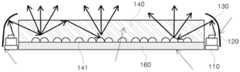
도 2는 본 발명에 따른 차량용 면조명의 요부를 도시한 요부 개념도이고, 도 3은 도 2의 A-A' 단면도를 도시한 개념도이다.2 is a conceptual view illustrating main parts of a surface light for a vehicle according to the present invention, and FIG. 3 is a conceptual view illustrating a sectional view taken along line A-A 'of FIG. 2.
도시된 도면 2 및 도 3을 참조하면, 본 발명에 따른 차량용 면조명은 다수의 광원(120)을 포함하는 광원모듈과, 상기 광원(120)에서 출사한 광을 가이드 하는 광가이드부재(140)를 포함하되, 상기 광가이드부재(140) 표면에 형성되는 광반사패턴(141)을 포함하여 구성된다.2 and 3, the surface light for a vehicle according to the present invention includes a light source module including a plurality of
특히, 이 경우 상기 광원모듈은 상기 광가이드부재(140)의 일측 또는 양측에 배치되어 에지타입으로 광을 광가이드부재(140) 내부로 공급할 수 있도록 함이 바람직하다. 이 경우 상기 광가이드부재(140)의 표면에는 깊이 방향으로 음각의 요철형상의 광반사패턴(141)을 형성하여 광반사율을 높이고, 이를 통해 광추출효율을 향상시킬 수 있게 된다.In particular, in this case, the light source module is preferably disposed on one side or both sides of the
상기 광반사패턴(141)은 도 3에 도시된 것과 같이, 광가이드부재(140)의 측면부에 배치된 광원에서 출사되는 광을 가이드 하여 전방으로 유도할 수 있도록 광가이드부재의 깊이방향으로 형성되는 요철구조의 패턴으로 형성할 수 있으며, 이러한 패턴의 형성방법으로는 에칭공법(etching)이나 샌딩(sanding) 공법 등을 사용할 수 있다. 에칭 공법의 경우, 패턴의 밀도, 형상(원형, 타원형, 삼각형), 패턴의 깊이 조절을 통해 산란특성을 조절할 수 있으며, 광원으로 부터 나온 빛을 광가이드부재내로 도광시켜 광 균일도 및 차량용 램프에 요구되는 배광법규를 만족하는 배광규격을 형성할 수 있도록 구현할 수 있다.As shown in FIG. 3, the
나아가, 샌딩공법의 경우, 분사제의 종류(Glass bead, Zirconia bead, White alumina 등), 샌딩(sanding) 조건(압력, 속도, 거리) 조절을 통해 산란 특성을 제어(control)할 수 있으며 광원으로부터 나온 빛을 광가이드부재 내로 도광 시켜 광 균일도 및 배광 규격을 만족시킬 수 있다.Furthermore, in the sanding method, the scattering characteristics can be controlled by adjusting the type of propellant (Glass bead, Zirconia bead, White alumina, etc.), sanding conditions (pressure, speed, distance), and The emitted light can be guided into the optical guide member to satisfy the light uniformity and the light distribution standard.
또는, 광반사패턴을 형성함에 있어서, 상기 두 가지 방법을 각각 또는 혼합하여 사용할 수 있으며 패턴 가공을 통해 가우시안(gaussian)과 램버시안(lambertian) 특성을 조절하여 배광규격 및 광도 규격을 만족시킬 수 있다.Alternatively, in forming the light reflection pattern, the two methods may be used individually or in combination, and the light distribution standard and the luminous intensity standard may be satisfied by adjusting the Gaussian and Lambertian characteristics through pattern processing. .
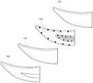
특히, 차량용 면조명의 경우, 설치 위치 및 구조에 따라 평판형상이 아닌 곡률형상의 조명으로 구현되는 경우가 대부분인바, 형상의 제약을 받게 되는데, 상술한 에칭, 샌딩 공법의 경우 가공하려고 하는 형상의 제약이 적은바, 금형에 패턴을 가공하여 광가이드부재를 사출함으로써, 곡선, 트위스트 형상등을 다채롭게 제작할 수 있게 되는바, 다양한 디자인으로 구현이 가능하게 된다.In particular, in the case of the surface lighting for vehicles, the lighting is curvature-shaped rather than flat, depending on the installation position and structure, which is subject to the limitation of the shape, in the case of the above-described etching and sanding method of the shape to be processed Less constraints, by processing the pattern on the mold and injecting the light guide member, it is possible to produce a variety of curves, twisted shapes, etc., it is possible to implement a variety of designs.
도 3에 도시된 것과 같이, 상기 광가이드부재(140)의 측면에는 광원모듈이 배치되며, 상기 광원모듈은 광원(120)을 실장하는 인쇄회로기판(110)을 포함하며, LED 등의 광원(120)의 주변부에 형성되어, 출사되는 광을 반사시켜 상기 광가이드부재(140) 내부로 재유도하는 재반사부재(130)을 포함하여 구성될 수 있다. 이러한 재반사부재는, Al, PC, PP, ABS, PBT 중 어느 하나 포함하는 재질로 형성될 수 있다. 상기 광원(120)은 인쇄회로기판(110) 상에 실장되는 구조로 구현되며, 측면발광형(side view type) 발광다이오드나 상부발광형(Top view type) 발광다이오드 어느 것이나 적용이 가능하다. 또한, 도시된 도면과 같이, 상기 광원(120)의 광출사의 방향이 광가이드부재(140)의 내부로 직접 향하는 것이 아니라, 상부 발광형으로 발광하게 되며, 이를 재반사부재(130)을 통해 광가이드부재(140)의 내부로 가이드 할 수 있도록 하는 구조로 구현할 수 있다. 특히, 이 경우 상기 재반사부재(130)은 상호 대향하는 방향에서 출사하는 광의 누설광을 상호 간에 재반사시켜 광의 진입효율을 높일 수 있는 장점이 구현되게 된다.As shown in FIG. 3, a light source module is disposed on a side surface of the
상기 인쇄회로기판(110)은 기판상에 회로패턴이 형성된 기판, 즉 PCB를 의미하며, 본 발명에서는 투명 재질의 인쇄회로기판인 것이 바람직하다. 종래의 차량 램프의 경우 FR4 인쇄회로기판을 이용함으로써 불투명하였지만, 본원발명과 같이 투명재질, 특히 투명 PET 인쇄회로기판을 이용함으로써 투명한 조명장치의 제공이 가능하게 된다. 또한, 본 발명에서는 일정 유연성을 확보하기 위하여 연성인쇄회로기판(FPCB)으로 형성 가능하다.The printed
상기 광가이드부재(140)은 기본적으로 투명재질의 합성수지재를 이용하여 광을 가이드 할 수 있도록 하는 기능을 수행할 수 있으며, 이를 위해 표면에 반사패턴(141)을 구비하여 내부에서 광의 반사율을 높일 수 있도록 할 수 있다. 상기 반사패턴은 차량용 후미등이 배치되는 다양한 곡률 등을 고려하여 기 형성된 광가이드 부재 표면에 음각의 요철을 형성할 수 있으며, 이를 테면 에칭(etching)이나 샌드 브라스트 방법(sand blast)으로 구현할 수 있다.The
특히, 본 발명에 따른 상기 광가이드부재(140)는 폴리메틸 메타크릴레이트(PMMA), 폴리스티렌(PS), 환상 올레핀 코폴리(COC), 폴리에틸렌 테레프탈레이트(PET), 아크릴수지, 우레탄 아크릴레이트(Urethane Acrylate), 에폭시 아크릴레이트(Epoxy Acrylate), 폴리에스테르 아크릴레이트(Polyester Acrylate), 폴리에테르 아크릴레이트(Polyether Acrylate), 폴리부타디엔 아크릴레이트(Polybutadiene Acrylate), 실리콘 아크릴레이트(Silicon Acrylate) 중 선택되는 어느 하나의 투명 수지를 이용하여 사출공정을 통해 구현할 수 있다. 물론, 이 경우 상기 광가이드부재(140)의 내부에는 실리콘(sillicon), 실리카(silica), 글라스버블(glass bubble), PMMA, 우레탄(urethane), Zn, Zr, Al2O3, 아크릴(acryl) 중 선택되는 적어도 어느 하나로 구성되는 광을 확산시키기 위한 확산 물질을 비드 형태로 삽입하여 광추출 효율을 극대화시킬 수도 있다. 이러한 확산물질의 일예로는 내부에 중공(또는 공극)이 형성된 다수의 비드(bead)가 혼합 및 확산된 형태로 더 포함될 수 있으며, 이러한 비드는 광의 반사 및 확산특성을 향상시키는 역할을 한다.In particular, the
아울러, 도 3에 도시된 것과 같이, 본 발명에 따른 광가이드부재의 하부에는 반사부재(160)를 더 포함하여 형성됨이 바람직하다.In addition, as shown in Figure 3, it is preferable that the lower portion of the light guide member according to the present invention further comprises a
상기 반사부재(160)는 반사효율의 높은 재질로 형성됨으로써 광원(160)에서 출사되는 광을 광가이드부재(140)이 위치하는 상부로 반사시켜 광손실을 줄이는 역할을 한다.The
이러한 반사부재(160)는 필름형태로 이루어질 수 있으며, 빛의 반사특성 및 빛의 분산을 촉진하는 특성을 구현하여 위하여 백색안료를 분산 함유하는 합성 수지를 포함하여 형성될 수 있다.The
예컨대 백색안료로서는 산화티탄, 산화알루미늄, 산화아연, 탄산연, 황산바륨, 탄산칼슘 등이 이용될 수 있으며, 합성 수지로서는 폴리에틸엔 테레프탈레이트, 폴리에틸렌 나프탈레이트, 아크릴수지, 콜리카보네이트, 폴리스티렌, 폴리올레핀, 셀룰로소스 아세테이트, 내후성 염화비닐 등이 이용될 수 있으나, 이에 한정되는 것은 아니다. 상기 반사부재(160)의 표면에는 반사패턴이 형성될 수 있으며, 반사패턴은 입사되는 광을 산란 및 분산시킴으로써 광가이드부재(140)에 광이 균일하게 전달되도록 하는 역할을 한다. 반사패턴의 형성은 TiO2, CaCo3, BaSo4, Al2O3, Silicon, PS 중 어느 하나를 포함하는 반사잉크를 이용하여 반사부재(160) 표면에 인쇄함으로써 이루어질 수 있으나 이에 한정되는 것은 아니다.For example, titanium oxide, aluminum oxide, zinc oxide, lead carbonate, barium sulfate, calcium carbonate may be used as the white pigment, and polyethylene terephthalate, polyethylene naphthalate, acrylic resin, colicarbonate, polystyrene, polyolefin may be used as the synthetic resin. , Cellulose source acetate, weather resistant vinyl chloride, etc. may be used, but is not limited thereto. A reflective pattern may be formed on the surface of the
또한, 반사부재(160)로서는 필름을 대신하여 투명 PET를 이용할 수도 있다. 또한 상기 반사부재의 표면에 반사패턴을 구비하여 반사효율을 높일 수 있도록 하며, 이러한 반사패턴의 구조는 복수의 돌출된 패턴을 구비하는 구조로 이루어지며, 빛의 산란효과를 증대시키기 위하여 도트(dot) 패턴 형상, 프리즘 형상, 렌티큘러 형상, 렌즈형상 또는 이들의 조합형상으로 이루어질 수 있으나, 이에 한정되는 것은 아니다. 또한, 반사패턴의 단면 형상은 삼각형, 사각형, 반원형, 사인파형 등 다양한 형상을 갖는 구조로 이루어질 수 있다.As the
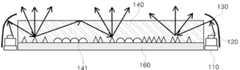
도 3에서 도시한 구조의 광원모듈의 구조에 더하여, 본 발명에 따른 차량용 면광원은 도 2에서 제시한 요부 개념도와 같이, 광가이드부재(140)의 내부 일부 영역에 실장홈(142)를 형성하여 그 내부에 LED 등의 광원을 실장하는 구조의 내부 광원군(210)을 더 포함하는 구조로 구현하는 것도 가능하다. 이는 차량의 후미등과 같이, 방향지시등이나 제동등 서로 다른 광을 구현하여 신호를 전달하는 영역을 분획하고자 하는 경우에 상기 내부광원군(210)을 추가로 형성하고, 상기 실장홈(142)가 형성하는 일영역(200)의 내부로 광이 유도될 수 있도록 하며, 이 경우 상기 일영역(200)에 해당하는 광가이드부재 표면에도 상술한 광반사패턴이 구현될 수 있다.In addition to the structure of the light source module having the structure shown in FIG. 3, the surface light source for a vehicle according to the present invention forms a mounting
도 4 및 도 5는 도 3에서 상술한 광반사패턴의 다양한 적용예를 도시한 개념도이다.4 and 5 are conceptual views illustrating various application examples of the light reflection pattern described above with reference to FIG. 3.
본 발명에 따른 광반사패턴(141)은 상술한 것과 같이, 광가이드부재(140)의 표면에 요철구조(음각형상)로 구현되며, 도 3과 같은 반구형, 도 4와 같은 피라미드형, 또는 도 5와 같은 반구형과 피라미드형의 조합구조 등 다양한 형상으로 조합이 가능하다.As described above, the
도 6은 도 2 내지 도 5에서 상술한 본 발명에 따른 차량용 면조명의 구현예를 도시한 것이다.6 illustrates an embodiment of a surface light for a vehicle according to the present invention described above with reference to FIGS. 2 to 5.
기본적으로 도 2에서 상술한 광가이드부재와 광원모듈을 포함하는 차량용면조명(100)의 구조에 하부에 반사부재(160), 상부에 확산플레이트(170), 상기 확산플레이트(170)의 상부에 배치되는 외부렌즈(180)이 더 결합하여 차량용 면조명으로 구현할 수 있다. 상기 반사부재(160)은 상술한 것과 같이 다양한 재료로 구현이 가능하며, 일예로 백색레진(white resin)을 적용하여 반사율을 향상시킬 수 있으며, 확산플레이트(170)의 경우에도 확산제나 표면조도를 조절하여 다양한 질감을 부여할 수 있어 점등시 심미감을 형성할 수도 있다.Basically, in the structure of the
상기 확산프레이트(170)의 표면에 표면조도를 부여하는 것은 상술한 에칭이나 샌딩공법을 적용할 수 있다.The surface roughness of the
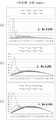
도 7 및 도 8은 본 발명에 따른 광가이드부재에 에칭(etching)을 통해 광반사패턴을 구현하고, 이렇게 제조된 광가이드부재의 표면반사특성(BSDF)을 측정한 결과를 도시한 것으로, 도 7은 에칭 각도별 산란피크를 측정한 결과이며, 도 8은 에칭 각도별 렘버시안 및 가우시안의 비율을 측정한 결과를 확인한 것으로, 결과적으로 가우시안의 양의 증가되며, Ra 도 증가, 렘버시안의 양도 증가됨을 확인할 수 있는 바, 본 발명에 따른 광반사패턴 조절을 통해 산란특성을 조절할 수 있음을 확인할 수 있다.7 and 8 illustrate a result of measuring a light reflection pattern by etching an optical guide member according to the present invention and measuring the surface reflection characteristics (BSDF) of the optical guide member thus manufactured. 7 is a result of measuring the scattering peak for each etching angle, Figure 8 is a result of measuring the ratio of the lemversian and Gaussian by the etching angle, as a result, the amount of Gaussian is increased, Ra is also increased, the transfer of lemversian It can be seen that the increased, the scattering characteristics can be adjusted by adjusting the light reflection pattern according to the present invention.
도 9 및 도 10은 상술한 샌딩공법을 적용하여 광가이드부재에 광반사패턴을 구현하고, 이렇게 제조된 광가이드부재의 표면반사특성(BSDF)를 측정한 결과로, 도 7 및 도 8에서 측정된 결과와 유사하게, 가우시안의 양의 증가되며, Ra 도 증가, 렘버시안의 양도 증가됨을 확인할 수 있는 바, 본 발명에 따른 광반사패턴 조절을 통해 산란특성을 조절할 수 있음을 확인할 수 있다.
9 and 10 are results of measuring the light reflection pattern on the light guide member by applying the above-described sanding method, and measuring the surface reflection characteristics (BSDF) of the light guide member thus manufactured, measured in FIGS. 7 and 8. Similar to the result, it can be seen that the amount of Gaussian is increased, Ra is also increased, and the amount of lemversian is increased, and thus the scattering characteristics can be adjusted by adjusting the light reflection pattern according to the present invention.
상술한 본 발명에 따른 차량용 면광원은 후미등(Tail) & 정지등(Stop) 및 방향지시등(turn signal)에 적용될 수 있다. 즉, 본 발명에 따른 조명장치는 조명이 필요로 하는 다양한 램프장치, 이를테면 차량용 램프, 가정용 조명장치, 산업용 조명장치에 적용이 가능하다. 예컨대 차량용 램프에 적용되는 경우, 헤드라이트, 차량실내조명, 도어스카프, 후방라이트 등에도 적용이 가능하다. 추가적으로 본 발명의 조명장치는 액정표시장치에 적용되는 백라이트 유닛 분야에도 적용 가능하며, 이외에도 현재 개발되어 상용화되었거나 향후 기술발전에 따라 구현 가능한 모든 조명관련 분야에 적용 가능하다고 할 것이다.The surface light source for a vehicle according to the present invention described above may be applied to a tail light & a stop light and a turn signal. That is, the lighting device according to the present invention is applicable to various lamp devices that require lighting, such as a vehicle lamp, a home lighting device, an industrial lighting device. For example, when applied to a vehicle lamp, it is also applicable to headlights, vehicle interior lighting, doorscar, rear lights and the like. In addition, the lighting apparatus of the present invention can be applied to the field of the backlight unit applied to the liquid crystal display device, and can be applied to all the lighting related fields that are currently developed and commercialized or can be implemented according to future technology development.
전술한 바와 같은 본 발명의 상세한 설명에서는 구체적인 실시예에 관해 설명하였다. 그러나 본 발명의 범주에서 벗어나지 않는 한도 내에서는 여러 가지 변형이 가능하다. 본 발명의 기술적 사상은 본 발명의 기술한 실시예에 국한되어 정해져서는 안 되며, 특허청구범위뿐만 아니라 이 특허청구범위와 균등한 것들에 의해 정해져야 한다.In the detailed description of the invention as described above, specific embodiments have been described. However, many modifications are possible without departing from the scope of the invention. The technical spirit of the present invention should not be limited to the described embodiments of the present invention, but should be determined not only by the claims, but also by those equivalent to the claims.
110: 인쇄회로기판
120: 광원
130: 재반사부재
140: 광가이드부재
141: 광반사패턴
142: 실장홈
160: 반사부재
210: 내부광원군110: printed circuit board
120: light source
130: re-reflective member
140: optical guide member
141: light reflection pattern
142: mounting groove
160: reflective member
210: internal light source group
Claims (13)
Translated fromKorean상기 반사부재 상에 배치되는 광가이드부재;
상기 반사부재 상면에 배치되어, 상기 광가이드부재에 의해 매립되는 복수개의 광반사패턴;
상기 광가이드부재 측면에 배치되는 광원모듈; 및
상기 광원모듈과 이격되어 배치되고, 곡률을 갖는 재반사부재를 포함하고,
상기 광원모듈은 인쇄회로기판, 상기 인쇄회로기판 상에 배치되는 복수개의 광원을 포함하고,
상기 광원은 상부발광형 다이오드이고,
상기 복수개의 광원으로부터 출사된 광은 상기 재반사부재의 내측에서 반사되어 상기 광가이드부재의 측면으로 입사되고, 상기 광가이드부재의 측면에서 입사된 광은 상기 광반사패턴에 반사되어 상기 광가이드부재의 상면으로 빛이 방출되고,
상기 재반사부재는 상기 인쇄회로기판의 일측과 이격되어 배치되어, 상기 광가이드부재의 높이보다 높게 형성되는 차량용 면조명.Reflective member;
An optical guide member disposed on the reflective member;
A plurality of light reflection patterns disposed on an upper surface of the reflective member and buried by the light guide member;
A light source module disposed on the side of the light guide member; And
It is disposed spaced apart from the light source module, and includes a re-reflection member having a curvature,
The light source module includes a printed circuit board and a plurality of light sources disposed on the printed circuit board,
The light source is a top light emitting diode,
Light emitted from the plurality of light sources is reflected inside the re-reflective member to be incident to the side of the light guide member, and light incident from the side of the light guide member is reflected to the light reflection pattern to reflect the light guide member. Light is emitted to the top of the
The re-reflective member is disposed spaced apart from one side of the printed circuit board, the surface light for a vehicle is formed higher than the height of the light guide member.
상기 광반사패턴은 상기 광가이드부재의 깊이 방향으로 음각의 요철이 형성되고, 상기 요철은 반구형 또는 피라미드 형 또는 반구형과 피라미드 형의 조합 구조를 포함하는 차량용 면조명.The method according to claim 1,
The light reflection pattern is a concave-convex irregularities are formed in the depth direction of the light guide member, the concave-convex surface comprises a hemispherical or pyramidal or a combination structure of hemispherical and pyramidal.
상기 광반사패턴의 밀도는 위치에 따라 상이하게 배치되고, 상기 광반사패턴은 상기 광원모듈에서 상기 광가이드부재의 중심부로 갈수록 패턴 밀도가 높아지는 차량용 면조명.The method according to claim 2,
The density of the light reflection pattern is differently disposed according to the position, the light reflection pattern is a vehicle surface illumination is increased in the pattern density from the light source module toward the center of the light guide member.
상기 광반사패턴은 TiO2, CaCO3, BaSO4, Al2O3, Silicon, PS 중 어느 하나의 물질을 포함하는 차량용 면조명.The method according to any one of claims 1,2 and 4,
The light reflection pattern is a vehicle surface lighting comprising any one material of TiO2 , CaCO3 , BaSO4 , Al2 O3 , Silicon, PS.
상기 반사부재는 투명 PET, 백색(white) PET, Ag 시트 중 어느 하나인 차량용 면조명.The method according to any one of claims 1,2 and 4,
The reflective member is a vehicle surface lighting of any one of transparent PET, white PET, Ag sheet.
상기 광가이드부재는 실리콘(sillicon), 실리카(silica), 글라스버블(glass bubble), PMMA, 우레탄(urethane), Zn, Zr, Al2O3, 아크릴(acryl) 중 선택되는 적어도 어느 하나로 구성되는 광을 확산시키기 위한 확산 물질을 더 포함하는 차량용 면조명.The method according to any one of claims 1,2 and 4,
The optical guide member is composed of at least one selected from silicon, silica, glass bubble, PMMA, urethane, Zn, Zr, Al2 O3 , and acryl. The vehicle surface lighting further comprising a diffusing material for diffusing light.
상기 광가이드부재는 일영역에 복수개의 광원을 실장하는 실장홈과, 상기 실장홈에 삽입되어 배치되는 내부광원군을 더 포함하는 차량용 면조명.The method according to any one of claims 1,2 and 4,
The light guide member further comprises a mounting groove for mounting a plurality of light sources in one region, and an internal light source group inserted into the mounting groove.
상기 내부광원군은 상기 실장홈이 형성하는 내부영역의 중심방향으로 광을 출사하는 차량용 면조명.The method according to claim 10,
The internal light source group is a surface light for a vehicle for emitting light toward the center of the inner region formed by the mounting groove.
상기 광가이드부재 상에 배치되는 확산플레이트와, 상기 확산플레이트 상에 배치되는 외부렌즈를 더 포함하는 차량용 면조명.The method according to any one of claims 1,2 and 4,
And a diffusion plate disposed on the light guide member and an external lens disposed on the diffusion plate.
Priority Applications (1)
| Application Number | Priority Date | Filing Date | Title |
|---|---|---|---|
| KR1020120147658AKR102012744B1 (en) | 2012-12-17 | 2012-12-17 | Automobile lamp |
Applications Claiming Priority (1)
| Application Number | Priority Date | Filing Date | Title |
|---|---|---|---|
| KR1020120147658AKR102012744B1 (en) | 2012-12-17 | 2012-12-17 | Automobile lamp |
Publications (2)
| Publication Number | Publication Date |
|---|---|
| KR20140078372A KR20140078372A (en) | 2014-06-25 |
| KR102012744B1true KR102012744B1 (en) | 2019-08-21 |
Family
ID=51130001
Family Applications (1)
| Application Number | Title | Priority Date | Filing Date |
|---|---|---|---|
| KR1020120147658AActiveKR102012744B1 (en) | 2012-12-17 | 2012-12-17 | Automobile lamp |
Country Status (1)
| Country | Link |
|---|---|
| KR (1) | KR102012744B1 (en) |
Cited By (1)
| Publication number | Priority date | Publication date | Assignee | Title |
|---|---|---|---|---|
| KR102283108B1 (en)* | 2020-12-04 | 2021-07-29 | 주식회사 삼광테라피 | Light guide plate structure of double layer and manufacturing method thereof |
Families Citing this family (6)
| Publication number | Priority date | Publication date | Assignee | Title |
|---|---|---|---|---|
| KR20160026403A (en)* | 2014-09-01 | 2016-03-09 | 엘지전자 주식회사 | Head light and method for emitting light the same |
| KR102435848B1 (en)* | 2015-03-31 | 2022-08-24 | 서울반도체 주식회사 | Light device of vehicle |
| CN106287486B (en)* | 2016-08-30 | 2020-05-15 | 嘉兴海拉灯具有限公司 | Vehicle lamp fixing structure and mounting method thereof |
| KR102804124B1 (en) | 2017-02-02 | 2025-05-09 | 엘지이노텍 주식회사 | Lighting apparatus |
| KR102564889B1 (en)* | 2018-02-08 | 2023-08-09 | 주식회사 아모센스 | Rear lamp module of vehicle and rear combination lamp having the same |
| CN115435295A (en)* | 2021-06-01 | 2022-12-06 | 常州星宇车灯股份有限公司 | Light emitting device and vehicle lamp |
Citations (1)
| Publication number | Priority date | Publication date | Assignee | Title |
|---|---|---|---|---|
| JP2008130279A (en)* | 2006-11-17 | 2008-06-05 | Nichia Chem Ind Ltd | Planar light emitting device and manufacturing method thereof |
Family Cites Families (3)
| Publication number | Priority date | Publication date | Assignee | Title |
|---|---|---|---|---|
| KR100882801B1 (en)* | 2007-04-25 | 2009-02-09 | 박휴완 | LGP Illuminator |
| CN101836037A (en)* | 2007-08-22 | 2010-09-15 | 三菱丽阳株式会社 | Surface light source device |
| KR101181012B1 (en) | 2010-07-30 | 2012-09-07 | 기아자동차주식회사 | Light guide for rear lamp |
- 2012
- 2012-12-17KRKR1020120147658Apatent/KR102012744B1/enactiveActive
Patent Citations (1)
| Publication number | Priority date | Publication date | Assignee | Title |
|---|---|---|---|---|
| JP2008130279A (en)* | 2006-11-17 | 2008-06-05 | Nichia Chem Ind Ltd | Planar light emitting device and manufacturing method thereof |
Cited By (1)
| Publication number | Priority date | Publication date | Assignee | Title |
|---|---|---|---|---|
| KR102283108B1 (en)* | 2020-12-04 | 2021-07-29 | 주식회사 삼광테라피 | Light guide plate structure of double layer and manufacturing method thereof |
Also Published As
| Publication number | Publication date |
|---|---|
| KR20140078372A (en) | 2014-06-25 |
Similar Documents
| Publication | Publication Date | Title |
|---|---|---|
| KR102012744B1 (en) | Automobile lamp | |
| CN104995452B (en) | lighting unit for vehicle | |
| KR102224459B1 (en) | Geometric Lighting Device and Vehicle Lighting Device Using the Same | |
| KR102012746B1 (en) | Automobile lamp | |
| CN104813098A (en) | Illuminating device and vehicle lamp comprising same | |
| KR102085256B1 (en) | Light unit and Automobile lamp unit using the same | |
| KR102005539B1 (en) | Lamp unit for automobile | |
| KR20160047250A (en) | Light unit and Lamp unit for automobile of using the same | |
| EP3104071A1 (en) | Lighting apparatus | |
| KR102047833B1 (en) | Light unit and Lamp unit for automobile of using the same | |
| KR102125827B1 (en) | Lamp unit and automobile lamp using the same | |
| KR102014076B1 (en) | Lamp unit for automobile | |
| KR20170074035A (en) | Lighting device | |
| KR102497470B1 (en) | Lighting package and Automobile lamp using the same | |
| US11079074B2 (en) | Lighting device and vehicular lamp comprising same | |
| KR102125679B1 (en) | Illuminating device and lamp for vehicle including the same | |
| KR101971692B1 (en) | Light unit for automobile | |
| KR102005529B1 (en) | Automobile lamp | |
| KR102292690B1 (en) | Illuminating device and lamp for vehicle including the same | |
| KR102320144B1 (en) | Light unit and Automobile lamp unit using the same | |
| KR102146474B1 (en) | Lighting apparatus | |
| KR102047847B1 (en) | Illuminating device | |
| KR102023536B1 (en) | Lamp unit and automobile lamp using the same | |
| KR102461363B1 (en) | Illuminating device and lamp for vehicle including the same | |
| KR102060970B1 (en) | Lamp unit and automobile lamp using the same |
Legal Events
| Date | Code | Title | Description |
|---|---|---|---|
| PA0109 | Patent application | St.27 status event code:A-0-1-A10-A12-nap-PA0109 | |
| PG1501 | Laying open of application | St.27 status event code:A-1-1-Q10-Q12-nap-PG1501 | |
| PN2301 | Change of applicant | St.27 status event code:A-3-3-R10-R13-asn-PN2301 St.27 status event code:A-3-3-R10-R11-asn-PN2301 | |
| R17-X000 | Change to representative recorded | St.27 status event code:A-3-3-R10-R17-oth-X000 | |
| P22-X000 | Classification modified | St.27 status event code:A-2-2-P10-P22-nap-X000 | |
| R18-X000 | Changes to party contact information recorded | St.27 status event code:A-3-3-R10-R18-oth-X000 | |
| E13-X000 | Pre-grant limitation requested | St.27 status event code:A-2-3-E10-E13-lim-X000 | |
| P11-X000 | Amendment of application requested | St.27 status event code:A-2-2-P10-P11-nap-X000 | |
| P13-X000 | Application amended | St.27 status event code:A-2-2-P10-P13-nap-X000 | |
| PA0201 | Request for examination | St.27 status event code:A-1-2-D10-D11-exm-PA0201 | |
| R17-X000 | Change to representative recorded | St.27 status event code:A-3-3-R10-R17-oth-X000 | |
| P22-X000 | Classification modified | St.27 status event code:A-2-2-P10-P22-nap-X000 | |
| R18-X000 | Changes to party contact information recorded | St.27 status event code:A-3-3-R10-R18-oth-X000 | |
| D13-X000 | Search requested | St.27 status event code:A-1-2-D10-D13-srh-X000 | |
| P22-X000 | Classification modified | St.27 status event code:A-2-2-P10-P22-nap-X000 | |
| D14-X000 | Search report completed | St.27 status event code:A-1-2-D10-D14-srh-X000 | |
| E902 | Notification of reason for refusal | ||
| PE0902 | Notice of grounds for rejection | St.27 status event code:A-1-2-D10-D21-exm-PE0902 | |
| E13-X000 | Pre-grant limitation requested | St.27 status event code:A-2-3-E10-E13-lim-X000 | |
| P11-X000 | Amendment of application requested | St.27 status event code:A-2-2-P10-P11-nap-X000 | |
| P13-X000 | Application amended | St.27 status event code:A-2-2-P10-P13-nap-X000 | |
| E701 | Decision to grant or registration of patent right | ||
| PE0701 | Decision of registration | St.27 status event code:A-1-2-D10-D22-exm-PE0701 | |
| GRNT | Written decision to grant | ||
| PR0701 | Registration of establishment | St.27 status event code:A-2-4-F10-F11-exm-PR0701 | |
| PR1002 | Payment of registration fee | St.27 status event code:A-2-2-U10-U11-oth-PR1002 Fee payment year number:1 | |
| PG1601 | Publication of registration | St.27 status event code:A-4-4-Q10-Q13-nap-PG1601 | |
| R18-X000 | Changes to party contact information recorded | St.27 status event code:A-5-5-R10-R18-oth-X000 | |
| PN2301 | Change of applicant | St.27 status event code:A-5-5-R10-R13-asn-PN2301 St.27 status event code:A-5-5-R10-R11-asn-PN2301 | |
| PR1001 | Payment of annual fee | St.27 status event code:A-4-4-U10-U11-oth-PR1001 Fee payment year number:4 | |
| PR1001 | Payment of annual fee | St.27 status event code:A-4-4-U10-U11-oth-PR1001 Fee payment year number:5 | |
| PR1001 | Payment of annual fee | St.27 status event code:A-4-4-U10-U11-oth-PR1001 Fee payment year number:6 | |
| PR1001 | Payment of annual fee | St.27 status event code:A-4-4-U10-U11-oth-PR1001 Fee payment year number:7 |