KR102012688B1 - Apparatus and method for data communication using wireless power - Google Patents
Apparatus and method for data communication using wireless powerDownload PDFInfo
- Publication number
- KR102012688B1 KR102012688B1KR1020120055768AKR20120055768AKR102012688B1KR 102012688 B1KR102012688 B1KR 102012688B1KR 1020120055768 AKR1020120055768 AKR 1020120055768AKR 20120055768 AKR20120055768 AKR 20120055768AKR 102012688 B1KR102012688 B1KR 102012688B1
- Authority
- KR
- South Korea
- Prior art keywords
- signal
- target device
- carrier
- power
- output power
- Prior art date
- Legal status (The legal status is an assumption and is not a legal conclusion. Google has not performed a legal analysis and makes no representation as to the accuracy of the status listed.)
- Active
Links
Images


Classifications
- H—ELECTRICITY
- H04—ELECTRIC COMMUNICATION TECHNIQUE
- H04B—TRANSMISSION
- H04B5/00—Near-field transmission systems, e.g. inductive or capacitive transmission systems
- H04B5/70—Near-field transmission systems, e.g. inductive or capacitive transmission systems specially adapted for specific purposes
- H04B5/79—Near-field transmission systems, e.g. inductive or capacitive transmission systems specially adapted for specific purposes for data transfer in combination with power transfer
- H—ELECTRICITY
- H02—GENERATION; CONVERSION OR DISTRIBUTION OF ELECTRIC POWER
- H02J—CIRCUIT ARRANGEMENTS OR SYSTEMS FOR SUPPLYING OR DISTRIBUTING ELECTRIC POWER; SYSTEMS FOR STORING ELECTRIC ENERGY
- H02J50/00—Circuit arrangements or systems for wireless supply or distribution of electric power
- H02J50/10—Circuit arrangements or systems for wireless supply or distribution of electric power using inductive coupling
- H02J50/12—Circuit arrangements or systems for wireless supply or distribution of electric power using inductive coupling of the resonant type
- H—ELECTRICITY
- H04—ELECTRIC COMMUNICATION TECHNIQUE
- H04B—TRANSMISSION
- H04B5/00—Near-field transmission systems, e.g. inductive or capacitive transmission systems
- H04B5/20—Near-field transmission systems, e.g. inductive or capacitive transmission systems characterised by the transmission technique; characterised by the transmission medium
- H04B5/24—Inductive coupling
- H04B5/26—Inductive coupling using coils
- H04B5/266—One coil at each side, e.g. with primary and secondary coils
Landscapes
- Engineering & Computer Science (AREA)
- Computer Networks & Wireless Communication (AREA)
- Signal Processing (AREA)
- Power Engineering (AREA)
- Near-Field Transmission Systems (AREA)
Abstract
Translated fromKorean
Description
Translated fromKorean기술분야는 무선 전력을 이용하여, 데이터를 통신하는 장치 및 방법에 관한 것이다.TECHNICAL FIELD The art relates to apparatus and methods for communicating data using wireless power.
무선 전력전송에 대한 연구는 휴대기기 및 전기 자동차를 포함한 다양한 전기기기의 폭발적 증가로 인한 유선전력공급의 불편함 증가 및 기존 battery 용량의 한계 봉착 등을 극복하기 위해 시작되었다. 무선 전력 전송 기술들 중 하나는 RF 소자들의 공진(resonance) 특성을 이용한다. 공진 특성을 이용하는 무선 전력 전송 시스템은 전력을 공급하는 소스 디바이스와 전력을 공급받는 타겟 디바이스를 포함할 수 있다. 소스 디바이스가 타겟 디바이스에게 전력을 효율적으로 전송 위해서는 소스 디바이스의 상태에 대한 정보 및 타겟 디바이스의 상태에 대한 정보를 서로 주고 받아야 한다. 즉, 소스 디바이스와 타겟 디바이스 간에 통신을 수행할 필요가 있다.The research on wireless power transfer began to overcome the inconvenience of wired power supply and the limitation of existing battery capacity due to the explosive increase of various electric devices including mobile devices and electric vehicles. One of the wireless power transfer technologies utilizes the resonance characteristics of RF devices. The wireless power transfer system using the resonance characteristic may include a source device that supplies power and a target device that is powered. In order for the source device to efficiently transmit power to the target device, information about the state of the source device and information about the state of the target device should be exchanged with each other. In other words, it is necessary to perform communication between the source device and the target device.
일 측면에 있어서, 무선 전력을 이용한 데이터 통신 장치는 타겟 디바이스의 임피던스 변화에 대응하는 전력 신호를 출력하는 전력 증폭기의 출력 전력 신호를 검출하는 전력 신호 검출부, 상기 검출된 출력 전력 신호와 반송파의 위상이 변환된 신호를 합성하여 상기 검출된 출력 전력 신호로부터 상기 타겟 디바이스의 메시지를 복조하는 복조부, 소스 공진기의 크기를 고려하여, 상기 반송파의 위상을 제어하는 제어부 및 타겟 공진기와 상기 소스 공진기 간의 마그네틱 커플링을 통하여 상기 타겟 디바이스로 상기 반송파를 전송하고, 상기 타겟 디바이스로부터 상기 메시지를 수신하는 소스 공진부를 포함한다.In one aspect, a data communication apparatus using wireless power includes a power signal detector configured to detect an output power signal of a power amplifier that outputs a power signal corresponding to a change in impedance of a target device, and a phase of the detected output power signal and a carrier wave A demodulator for demodulating the message of the target device from the detected output power signal by synthesizing the converted signal, a controller for controlling the phase of the carrier in consideration of the size of a source resonator, and a magnetic couple between the target resonator and the source resonator And a source resonator for transmitting the carrier to the target device through a ring and receiving the message from the target device.
다른 일 측면에 있어서, 무선 전력을 이용한 데이터 통신 장치는 상기 출력 전력 신호의 크기의 변화에 기초하여, 상기 타겟 디바이스의 임피던스 변화를 감지하는 감지부를 더 포함할 수 있다.In another aspect, a data communication apparatus using wireless power may further include a detector configured to detect a change in impedance of the target device based on a change in the magnitude of the output power signal.
상기 전력 신호 검출부는 커플링 저항, 커플링 인덕터 및 커플링 캐패시터 중 적어도 하나를 이용하여, 상기 출력 전력 신호를 커플링하는 커플링부를 포함할 수 있다.The power signal detector may include a coupling unit configured to couple the output power signal by using at least one of a coupling resistor, a coupling inductor, and a coupling capacitor.
상기 커플링부는 상기 전력 증폭기와 상기 소스 공진기 사이에 연결된 전력 전송 라인(power line) 또는 그라운드 라인(ground line)으로부터 상기 출력 전력 신호를 커플링할 수 있다.The coupling unit may couple the output power signal from a power line or a ground line connected between the power amplifier and the source resonator.
상기 반송파는 상기 소스 공진기의 공진 주파수를 반송 주파수로 할 수 있다.The carrier wave may be a carrier frequency of a resonance frequency of the source resonator.
상기 전력 신호 검출부는 상기 반송파의 크기의 최대값과 상기 타겟 디바이스의 임피던스 변화에 대응하여 생성된 출력 전력 신호의 크기의 최대값의 차이만큼 상기 커플링 된 상기 출력 전력 신호의 크기를 제한하는 전력 제한부를 포함할 수 있다.The power signal detector is configured to limit the magnitude of the coupled output power signal by a difference between the maximum value of the magnitude of the carrier and the maximum value of the magnitude of the output power signal generated in response to the impedance change of the target device. It may include wealth.
상기 전력 신호 검출부는 상기 소스 공진기가 상기 타겟 디바이스를 웨이크 업(wak--up) 시키는 웨이크 업 신호를 전송하는 동안에는 상기 커플링 된 상기 출력 전력 신호의 수신을 제어하는 수신 제어부를 포함할 수 있다.The power signal detector may include a reception controller configured to control reception of the coupled output power signal while the source resonator transmits a wake-up signal for waking up the target device.
상기 복조부는 상기 검출된 출력 전력 신호와 상기 반송파와 동일한 위상의 신호를 합성하여 합성 신호를 생성하는 위상 합성부 및 상기 합성 신호와 기준 신호를 비교하여 "하이" 또는 "로우" 값을 출력하는 비교부를 포함할 수 있다.The demodulator combines the detected output power signal with a signal having the same phase as the carrier to generate a synthesized signal, and compares the synthesized signal with a reference signal to output a "high" or "low" value. It may include wealth.
상기 복조부는 상기 비교부에서 출력된 상기 "하이" 또는 "로우" 값에 기초하여, 상기 타겟 디바이스의 메시지를 복조할 수 있다.The demodulator may demodulate a message of the target device based on the “high” or “low” value output from the comparator.
상기 복조부는 상기 검출된 출력 전력 신호를 제1 신호 및 제2 신호로 분배하는 분배부, 상기 제1 신호와 상기 반송파와 위상이 동일한 신호를 합성하여, 제1 합성신호를 생성하는 동위상 합성부 및 상기 제2 신호와 상기 반송파와 위상이 반대인 신호를 합성하여, 제2 합성 신호를 생성하는 반대위상 합성부를 포함할 수 있다.The demodulator divides the detected output power signal into a first signal and a second signal, and an in-phase synthesizer that generates a first synthesized signal by synthesizing a signal having the same phase as the first signal and the carrier wave. And an antiphase synthesizing unit configured to synthesize a signal having a phase opposite to that of the second signal and the carrier to generate a second synthesized signal.
상기 복조부는 상기 제1 합성신호의 크기와 상기 제2 합성신호의 크기를 비교하여 "하이" 또는 "로우" 값을 출력하는 비교부를 더 포함할 수 있다.The demodulator may further include a comparator configured to output a “high” or “low” value by comparing the magnitude of the first composite signal with the magnitude of the second composite signal.
상기 복조부는 상기 제1 합성신호의 크기와 제1 기준 신호를 비교하여 "하이" 또는 "로우" 값을 출력하는 제1 비교부 및 상기 제2 합성신호의 크기와 제2 기준 신호를 비교하여 "하이" 또는 "로우" 값을 출력하는 제2 비교부를 더 포함할 수 있다.The demodulator compares the magnitude of the first synthesized signal with the first reference signal and outputs a "high" or "low" value, and compares the magnitude of the second synthesized signal with the magnitude of the second reference signal. And a second comparator for outputting a high or low value.
상기 복조부는 상기 제1 비교부에서 출력된 상기 "하이" 또는 "로우" 값과, 상기 제2 비교부에서 출력된 상기 "하이" 또는 "로우" 값을 동기화된 시간 별로 비교하여, 상기 타겟 디바이스의 메시지를 복조할 수 있다.The demodulator compares the "high" or "low" value output from the first comparator with the "high" or "low" value output from the second comparator for each synchronized time, thereby providing the target device. Can demodulate the message.
일 측면에 있어서, 무선 전력을 이용한 데이터 통신 장치는 소스 공진기와 타겟 공진기간의 마그네틱 커플링을 통하여, 상기 소스 공진기로부터 반송파를 수신하는 타겟 공진부, 상기 반송파 및 소스 디바이스와 타겟 디바이스간의 임피던스 미스매칭(mismatching)에 기초하여 메시지를 변조하는 변조부 및 상기 타겟 디바이스의 임피던스를 변경함으로써, 상기 임피던스 미스매칭을 제어하는 제어부를 포함한다.In one aspect, a data communication apparatus using wireless power includes a target resonator configured to receive a carrier wave from the source resonator through magnetic coupling between a source resonator and a target resonance period, and an impedance mismatch between the carrier and the source device and the target device. and a controller for controlling the impedance mismatch by changing an impedance of the target device and a modulator for modulating the message based on mismatching.
상기 제어부는 가변 부하에 흐르는 전류의 온/오프를 제어함으로써, 상기 타겟 디바이스의 임피던스 및 위상을 변경할 수 있다.The controller may change an impedance and a phase of the target device by controlling on / off of a current flowing in a variable load.
상기 제어부는 가변 부하로 동작하는 전류 소스를 통하여 상기 타겟 디바이스의 임피던스를 변경할 수 있다.The controller may change the impedance of the target device through a current source operating with a variable load.
상기 제어부는 상기 타겟 디바이스의 부하에 연결된 스위치의 온/오프를 이용하여, 상기 타겟 디바이스의 임피던스와 위상을 변경할 수 있다.The controller may change the impedance and the phase of the target device by using on / off of a switch connected to the load of the target device.
일 측면에 있어서, 무선 전력을 이용한 데이터 통신 방법은 타겟 디바이스의 임피던스 변화에 대응하는 전력 신호를 출력하는 전력 증폭기의 출력 전력 신호를 검출하는 단계, 상기 검출된 출력 전력 신호와 반송파의 위상이 변환된 신호를 합성하여 상기 검출된 출력 전력 신호로부터 상기 타겟 디바이스의 메시지를 복조하는 단계, 소스 공진기의 크기를 고려하여, 기 설정된 기준에 따라 상기 반송파의 위상을 제어하는 단계 및 타겟 공진기와 상기 소스 공진기 간의 마그네틱 커플링을 통하여 상기 타겟 디바이스로 상기 반송파를 전송하고, 상기 타겟 디바이스로부터 상기 메시지를 수신하는 단계를 포함한다.In one aspect, a data communication method using wireless power includes detecting an output power signal of a power amplifier that outputs a power signal corresponding to a change in impedance of a target device, wherein the detected output power signal and a phase of a carrier are converted. Demodulating a message of the target device from the detected output power signal by synthesizing a signal, controlling a phase of the carrier according to a predetermined reference in consideration of a size of a source resonator, and between a target resonator and the source resonator Transmitting the carrier to the target device via magnetic coupling, and receiving the message from the target device.
상기 출력 전력 신호를 검출하는 단계는 커플링 저항, 커플링 인덕터 및 커플링 캐패시터 중 적어도 하나를 이용하여, 상기 출력 전력 신호를 커플링하는 단계를 포함할 수 있다.The detecting of the output power signal may include coupling the output power signal using at least one of a coupling resistor, a coupling inductor, and a coupling capacitor.
상기 출력 전력 신호를 검출하는 단계는 상기 반송파의 크기의 최대값과 상기 타겟 디바이스의 임피던스 변화에 대응하여 생성된 출력 전력 신호의 크기의 최대값의 차이만큼 상기 커플링 된 상기 출력 전력 신호의 크기를 제한하는 단계를 포함할 수 있다.The detecting of the output power signal may include determining the magnitude of the coupled output power signal by a difference between the maximum value of the magnitude of the carrier and the maximum value of the magnitude of the output power signal generated in response to the impedance change of the target device. It may comprise the step of limiting.
상기 복조하는 단계는 상기 검출된 출력 전력 신호와 상기 반송파와 동일한 위상의 신호를 합성하여 합성 신호를 생성하는 단계 및 상기 합성 신호와 기준 신호를 비교하여 "하이" 또는 "로우" 값을 출력하는 단계를 포함할 수 있다.The demodulating may include generating a synthesized signal by synthesizing the detected output power signal with a signal having the same phase as the carrier and outputting a "high" or "low" value by comparing the synthesized signal with a reference signal. It may include.
상기 복조하는 단계는 상기 "하이" 또는 "로우" 값에 기초하여, 상기 타겟 디바이스의 메시지를 복조할 수 있다.The demodulating may demodulate a message of the target device based on the "high" or "low" value.
일 측면에 있어서, 무선 전력을 이용한 데이터 통신 방법은 소스 공진기와 타겟 공진기간의 마그네틱 커플링을 통하여, 상기 소스 공진기로부터 반송파를 수신하는 단계, 상기 반송파 및 소스 디바이스와 타겟 디바이스간의 임피던스 미스매칭(mismatching)에 기초하여 메시지를 변조하는 단계 및 상기 타겟 디바이스의 임피던스를 변경함으로써, 상기 임피던스 미스매칭을 제어하는 단계를 포함한다.In one aspect, a data communication method using wireless power may include receiving a carrier wave from the source resonator through magnetic coupling between a source resonator and a target resonance period, and mismatching impedance between the carrier and the source device and the target device. Modulating the message based on < RTI ID = 0.0 >) and < / RTI > controlling the impedance mismatch by changing the impedance of the target device.
상기 제어하는 단계는 가변 부하에 흐르는 전류의 온/오프를 제어함으로써, 상기 타겟 디바이스의 부하에 흐르는 전류를 제어하여 상기 타겟 디바이스의 임피던스를 변경할 수 있다.The controlling may control the current flowing in the load of the target device, thereby controlling the current flowing in the load of the target device, thereby changing the impedance of the target device.
무선 전력을 이용한 통신 장치는 타겟 디바이스로부터 수신한 변조된 메시지를 검출된 출력 전력 신호로부터 위상을 보상하여 복조할 수 있다.The communication apparatus using the wireless power may demodulate the modulated message received from the target device by compensating the phase from the detected output power signal.
무선 전력을 이용한 통신 장치는 타겟 디바이스의 부하와 병렬로 연결된 가변 부하에 흐르는 전류를 제어함으로써, 타겟 디바이스의 임피던스를 변경할 수 있고, 변경된 타겟 디바이스의 임피던스에 기초하여 메시지를 변조할 수 있다.The communication apparatus using the wireless power may change an impedance of the target device and modulate a message based on the changed impedance of the target device by controlling a current flowing in a variable load connected in parallel with the load of the target device.
소스 디바이스 상에 타겟 디바이스가 어느 위치에 놓이는 지에 관계없이, 타겟 디바이스가 전송하는 메시지를 무선 전력을 이용한 통신 장치는 복조할 수 있다. 따라서, 무선 전력을 이용한 통신 장치는 소스 디바이스와 타겟 디바이스간의 안정적인 통신 및 비트에러율(BER, Bit Error Rate)을 개선할 수 있다.Regardless of where the target device is placed on the source device, the communication device using the wireless power can demodulate the message transmitted by the target device. Therefore, the communication apparatus using the wireless power can improve the stable communication between the source device and the target device and the bit error rate (BER).
도 1은 예시적인 실시 예에 따른 무선 전력 전송 시스템을 나타낸다.
도 2는 일실시예에 따른 무선 전력을 이용한 데이터 통신 장치의 블록도이다.
도 3은 일실시예에 따른 타겟 디바이스의 메시지 전송을 나타낸 도면이다.
도 4는 일실시예에 따른 소스 디바이스 상에 위치하는 타겟 디바이스를 나타낸 도면이다.
도 5 내지 도 7은 일실시예에 따른 전력 신호 검출부(240)의 일 예를 나타낸 도면이다.
도 8은 일실시예에 따른 커플링부에 커플링 저항이 사용되는 경우의 커플링 전력을 나타낸 그래프이다.
도 9는 일실시예에 따른 커플링부에 커플링 캐패시터가 사용되는 경우의 커플링 전력을 나타낸 그래프이다.
도 10은 일실시예에 따른 커플링부에 커플링 인덕터가 사용되는 경우의 커플링 전력을 나타낸 그래프이다.
도 11은 일실시예에 따른 전력 제한부의 동작을 설명하기 위한 도면이다.
도 12는 일실시예에 따른 전력 제한부의 일 예를 나타낸 도면이다.
도 13은 도 12의 일실시예에 따른 전력 제한부의 입력 전력과 출력전력을 나타낸 그래프이다.
도 14 내지 도 16은 일실시예에 따른 복조부(260)의 일 예를 나타낸 도면이다.
도 17은 다른 일실시예에 따른 무선 전력을 이용한 데이터 통신 장치의 블록도이다.
도 18은 일실시예에 따른 무선 전력을 이용한 데이터 통신 방법의 흐름도이다.
도 19는 일 실시예에 따른 전기 자동차(electric vehicle) 충전 시스템을 나타낸다.
도 20 및 도 21은 일 실시예에 따른 무선 전력 수신 장치 및 무선 전력 전송 장치가 탑재될 수 있는 어플리케이션들을 나타낸다.
도 22는 일 실시예에 따른 무선 전력 전송 장치 및 무선 전력 수신 장치의 구성 예를 나타낸다.1 illustrates a wireless power transfer system according to an exemplary embodiment.
2 is a block diagram of a data communication device using wireless power according to an embodiment.
3 is a diagram illustrating a message transmission of a target device according to an embodiment.
4 illustrates a target device located on a source device according to an embodiment.
5 to 7 are diagrams illustrating an example of the
8 is a graph illustrating coupling power when a coupling resistor is used in a coupling unit according to an exemplary embodiment.
9 is a graph illustrating coupling power when a coupling capacitor is used in the coupling unit according to an exemplary embodiment.
10 is a graph illustrating coupling power when a coupling inductor is used in a coupling unit, according to an exemplary embodiment.
11 is a diagram for describing an operation of a power limiting unit, according to an exemplary embodiment.
12 is a diagram illustrating an example of a power limiting unit according to an embodiment.
FIG. 13 is a graph illustrating input power and output power of the power limiter according to the embodiment of FIG.
14 to 16 are diagrams showing an example of a
17 is a block diagram of a data communication apparatus using wireless power according to another exemplary embodiment.
18 is a flowchart of a data communication method using wireless power, according to an embodiment.
19 illustrates an electric vehicle charging system according to one embodiment.
20 and 21 illustrate applications in which a wireless power receiver and a wireless power transmitter may be mounted, according to an embodiment.
22 illustrates an example of a configuration of a wireless power transmitter and a wireless power receiver according to an embodiment.
이하, 일측에 따른 실시예를 첨부된 도면을 참조하여 상세하게 설명한다.Hereinafter, exemplary embodiments of the present invention will be described in detail with reference to the accompanying drawings.
도 1은 예시적인 실시 예에 따른 무선 전력 전송 시스템을 나타낸다.1 illustrates a wireless power transfer system according to an exemplary embodiment.
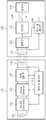
도 1을 참조하면, 일 실시 예에 따른 무선 전력 전송 시스템은 소스 디바이스(110) 및 타겟 디바이스(120)를 포함한다. 소스 디바이스(110)는 무선 전력을 공급하는 디바이스를 의미하며, 디바이스에는 패드, 단말, TV, 의료기기, 전기 자동차(electric vehicle) 등 전력을 공급할 수 있는 모든 전자기기가 포함될 수 있다. 타겟 디바이스(120)는 무선 전력을 공급받는 디바이스를 의미하며, 전력을 필요로 하는 모든 전자기기가 포함될 수 있다. 이때, 전자기기에는 패드, 단말, 태블릿, 의료기기, 전기 자동차(electric vehicle) 등이 포함될 수 있다.Referring to FIG. 1, a wireless power transmission system according to an embodiment includes a
소스 디바이스(110)는 AC/DC 컨버터(111), Power Detector(113), 전력변환부(114), 제어 및 통신부(115) 및 소스 공진기(116)을 포함한다.The
타겟 디바이스(120)는 타겟 공진기(121), 정류부(122), DC/DC 컨버터(123), 스위치부(124), 충전부(125) 및 제어 및 통신부(126)를 포함한다.The
AC/DC 컨버터(111)는 일정한 레벨의 DC 전압을 출력하거나, 제어 및 통신부(115)의 제어에 따라 DC 전압의 출력 레벨을 조정할 수 있다.The AC /
Power Detector(113)는 AC/DC 컨버터(111)의 출력 전류 및 전압을 검출하고, 검출된 전류 및 전압에 대한 정보를 제어 및 통신부(115)로 전달한다. 또한, Power Detector(113)는 전력변환부(114)의 입력 전류 및 전압을 검출할 수 도 있다.The
전력변환부(114)는 수 MHz ~ 수십 MHz 대역의 스위칭 펄스 신호에 의하여 일정한 레벨의 DC 전압를 AC 전압으로 변환함으로써 전력을 생성할 수 있다. 즉, 전력변환부(114)는 공진 주파수를 이용하여 직류 전압을 교류 전압으로 변환함으로써, 타겟 디바이스에서 사용되는 "통신용 전력" 또는 "충전용 전력"을 생성할 수 있다. 여기서, "통신용 전력"은 타겟 디바이스의 통신 모듈 및 프로세서를 활성화 시키기 위한 에너지를 의미한다. 상기 활성화 시키기 위한 에너지라는 의미에서 "통신용 전력"은 웨이크 업(wak--up)전력이라고 불리울 수 있다. "통신용 전력"은 CW(constant wave)의 형태로 일정 시간 동안 전송될 수 있다. "충전용 전력"은 타겟 디바이스와 연결된 또는 타겟 디바이스에 포함된 배터리를 충전 시키기 위한 에너지를 의미한다. "충전용 전력"은 소정 시간 동안 계속 전송될 수 있으며, "통신용 전력" 보다 높은 전력 레벨로 전송될 수 있다.The
제어 및 통신부(115)는 스위칭 펄스 신호의 주파수를 제어할 수 있다. 제어 및 통신부(115)의 제어에 의하여 스위칭 펄스 신호의 주파수가 결정될 수 있다. 제어 및 통신부(115)는 전력변환부(114)를 제어함으로써, 타겟 디바이스(120)에 전송하기 위한 변조 신호를 생성할 수 있다. 즉, 제어 및 통신부(115)는 인-밴드 통신"을 통해 상기 타겟 디바이스에 다양한 메시지를 전송할 수 있다. 또한, 제어 및 통신부(115)는 반사파를 검출하고, 반사파의 포락선을 통해 타겟 디바이스로부터 수신되는 신호를 복조할 수 있다.The control and
제어 및 통신부(115)는 다양한 방법을 통해, 인-밴드 통신을 수행하기 위한 변조 신호를 생성할 수 있다. 제어 및 통신부(115)는 스위칭 펄스 신호를 온/오프 함으로써, 변조신호를 생성할 수 있다. 또한, 제어 및 통신부(115)는 델타-시그마 변조를 수행하여, 변조신호를 생성할 수 있다. 제어 및 통신부(115)는 일정한 포락선을 가지는 펄스폭 변조신호를 생성할 수 있다.The control and
한편, 제어 및 통신부(115)는 공진 주파수가 아닌 별도의 통신 채널을 이용하는 아웃-밴드 통신을 수행할 수 도 있다. 제어 및 통신부(115)는 Zigbee, Bluetooth 등의 통신 모듈을 포함할 수 있다. 제어 및 통신부(115)는 아웃-밴드 통신을 통해 타겟 디바이스(120)와 데이터를 송수신 할 수 있다.Meanwhile, the control and
소스 공진기(116)는 전자기(electromagnetic) 에너지를 타겟 공진기(121)로 전달(transferring)한다. 즉, 소스 공진기(116)는 타겟 공진기(121)와의 마그네틱 커플링을 통해 "통신용 전력" 또는 "충전용 전력"을 타겟 디바이스(120)로 전달한다.The
타겟 공진기(121)는 소스 공진기(116)로부터 전자기(electromagnetic) 에너지를 수신한다. 즉, 타겟 공진기(121)는 소스 공진기(116)와의 마그네틱 커플링을 통해 소스 디바이스(110)로부터 "통신용 전력" 또는 "충전용 전력"을 수신한다. 또한, 타겟 공진기(121)는 인-밴드 통신을 통해 상기 소스 디바이스로부터 다양한 메시지를 수신할 수 있다.The
정류부(122)는 교류 전압을 정류함으로써, DC 전압을 생성한다. 즉, 정류부(122)는 타겟 공진기(121)에 수신된 교류 전압을 정류한다.The
DC/DC 컨버터(123)는 정류부(122)에서 출력되는 DC 전압의 레벨을 충전부(125)의 용량에 맞게 조정한다. 예를 들어, DC/DC 컨버터(123)는 정류부(122)에서 출력되는 DC 전압의 레벨을 3~10Volt로 조정할 수 있다.The DC /
스위치부(124)는 제어 및 통신부(126)의 제어에 따라 온/오프 된다. 스위치부(124)가 오프되는 경우, 소스 디바이스(110)의 제어 및 통신부(115)는 반사파를 검출하게 된다. 즉, 스위치부(124)가 오프되는 경우, 소스 공진기(116)와 타겟 공진기(121) 사이의 마그네틱 커플링이 제거 될 수 있다.The
충전부(125)는 배터리를 포함할 수 있다. 충전부(125)는 DC/DC 컨버터(123)로부터 출력되는 DC 전압을 이용하여 배터리를 충전할 수 있다.The charging
제어 및 통신부(126)는 공진 주파수를 이용하여 데이터를 송수신하는 인-밴드 통신을 수행할 수 있다. 이때, 제어 및 통신부(126)는 타겟 공진기(121)과 정류부(122) 사이의 신호를 검출하여 수신 신호를 복조하거나, 정류부(122)의 출력 신호를 검출하여 수신 신호를 복조할 수 있다. 즉, 제어 및 통신부(126)는 인-밴드 통신을 통해 수신된 메시지를 복조할 수 있다. 또한, 제어 및 통신부는 타겟 공진기(121)의 임피던스를 조정함으로써, 소스 디바이스(110)에 전송하는 신호를 변조할 수 있다. 또한, 제어 및 통신부는 스위치부(124)의 온/오프를 통해 소스 디바이스(110)에 전송하는 신호를 변조할 수 도 있다. 간단한 예로, 제어 및 통신부(126)는 타겟 공진기(121)의 임피던스를 증가 시킴으로써, 소스 디바이스(110)의 제어 및 통신부(115)에서 반사파가 검출되도록 할 수 있다. 반사파의 발생 여부에 따라, 소스 디바이스(110)의 제어 및 통신부(115)는 이진수 "0" 또는 "1"을 검출할 수 있다.The control and
한편, 제어 및 통신부(126)는 통신 채널을 이용하는 아웃-밴드 통신을 수행할 수 도 있다. 제어 및 통신부(126)는 Zigbee, Bluetooth 등의 통신 모듈을 포함할 수 있다. 제어 및 통신부(126)는 아웃-밴드 통신을 통해 소스 디바이스(110)와 데이터를 송수신 할 수 있다.
Meanwhile, the control and
도 2는 일실시예에 따른 무선 전력을 이용한 데이터 통신 장치의 블록도이다.2 is a block diagram of a data communication device using wireless power according to an embodiment.
무선 전력을 이용한 데이터 통신 장치는 주파수 발생부(210), AC/DC 컨버터(220), 전력 변환부(230), 전력 신호 검출부(240), 소스 공진부(250), 복조부(260), 제어부(270)를 포함한다.The data communication apparatus using wireless power includes a
주파수 발생부(210)는 공진 주파수를 발생시킨다. 공진 주파수는 제어부(270)에 의해 결정될 수 있다. 제어부(270)는 소스 디바이스와 타겟 디바이스 간의 임피던스 매칭 및 공진 주파수를 결정할 수 있다. AC/DC 컨버터(220)는 교류 신호를 정류하여 소정의 직류 신호로 변환할 수 있다. 전력 변환부(230)는 전력 증폭기(Power Amplifier, PA)를 통하여, 타겟 디바이스의 요청에 대응하는 크기로 입력 전력을 증폭할 수 있다. 전력 증폭기는 SMPS(Switching Mode Power Supply)에서 공급되는 전압(전력)에 의해서 구동될 수 잇다. SMPS는 AC/DC 컨버터의 역할을 수행할 수 있다. 전력증폭기(power amplifier)는 SMPS의 공급 전압에 기초하여, 교류 전력 신호를 생성할 수 있다.The
전력 신호 검출부(240)는 전력 변환부(230)에서 출력되는 출력 전력 신호를 검출한다. 전력 변환부(230)는 타겟 디바이스를 구동시킬 수 있는 웨이크 업 전력 신호를 생성할 수 있다. 이때, 전력 변환부(230)에서 생성된 교류 신호는 소스 공진기와 타겟 공진기 간의 공진 주파수를 반송 주파수로 하는 반송파로 이용될 수 있다.The
또한, 전력 변환부(230)는 타겟 디바이스의 임피던스가 변화하면, 변화하는 임피던스에 매칭된 새로운 출력 전력 신호를 출력할 수 있다. 제어부(270)는 타겟 디바이스의 임피던스 변화에 대응하여, 임피던스 매칭을 수행하고, 매칭에 따라 전력 변환부(230)에서 출력 되어야 할 새로운 출력 전력에 대한 정보를 전력 변환부(230)에 제공할 수 있다.In addition, when the impedance of the target device changes, the
타겟 디바이스는 임피던스를 변화시킴으로써, 소스 디바이스와 타겟 디바이스 간에 임피던스 미스매칭을 발생시킬 수 있다. 타겟 디바이스는 임피던스 미스매칭을 이용하여 메시지를 변조할 수 있다. 타겟 디바이스가 임피던스 미스매칭을 이용하여 메시지를 변조하는 방식을 로드 모듈레이션(Load modulation)이라고 부른다.The target device may generate impedance mismatching between the source device and the target device by changing the impedance. The target device may modulate the message using impedance mismatching. The manner in which the target device modulates the message using impedance mismatching is called load modulation.
출력 전력 신호에는 소스 공진기에서 타겟 공진기로 공진 주파수를 이용하여 전송되는 신호 및 타겟 디바이스의 임피던스 미스매칭에 따른 로드 모듈레이션 주파수를 이용하여 전송되는 신호가 포함될 수 있다. 로드 모듈레이션 주파수는 공진 주파수를 반송 주파수로 하되, 임피던스 미스매칭에 따라 변경된 주파수를 의미할 수 있다. 또한, 로드 모듈레이션 신호의 크기 또는 위상은 타겟 디바이스가 소스 공진기 상에 놓인 위치에 따라 달라질 수 있다. 또한, 로드 모듈레이션 신호의 위상(phase)은 공진 주파수의 위상과 동위상이 아닐 수도 있다.The output power signal may include a signal transmitted using a resonance frequency from a source resonator to a target resonator and a signal transmitted using a load modulation frequency according to impedance mismatching of a target device. The load modulation frequency may refer to a resonance frequency as a carrier frequency but may mean a frequency changed according to impedance mismatching. Also, the magnitude or phase of the load modulation signal may vary depending on where the target device is placed on the source resonator. In addition, the phase of the load modulation signal may not be in phase with the phase of the resonant frequency.
출력 전력 신호는 소스 공진부(250)에 전달되고, 소스 공진부(250)는 출력 전력 신호를 타겟 디바이스로 전송한다.The output power signal is transmitted to the
전력 신호 검출부(240)는 전력 변환부(230)와 소스 공진부(250) 사이에 연결된 전력 전송 라인(Power Line) 또는 그라운드(Ground Line)으로부터 출력 전력 신호를 커플링 할 수 있다. 출력 전력 신호는 공진주파수의 교류신호로서, 플러스(+)단과 마이너스--)단 중 하나에서 커플링 될 수 있다.The
소스 공진부(250)는 공진 주파수에 실린 전력을 소스 공진기와 타겟 공진기간에 마그네틱 커플링을 통하여 전송할 수 있다. 즉, 소스 공진부(250)는 공진 주파수를 반송(carrier) 주파수로 하는 반송파를 전송할 수 있다.The
소스 공진부(250)는 로드 모듈레이션을 통하여 변조된 메시지를 수신할 수 있다.The
복조부(260)는 전력 신호 검출부(240)에서 검출된 출력 전력 신호와 공진주파수를 반송 주파수로 하는 반송파의 위상이 변환된 신호를 합성하여, 타겟 디바이스의 메시지를 복조 할 수 있다.The
검출된 출력 전력 신호는 타겟 디바이스의 주변 환경 및 타겟 디바이스의 임피던스 미스매칭에 따라 위상이 변화될 수 있다. 복조부(260)는 메시지가 반송파의 위상과 동일하지 않은 경우에도 복조될 수 있도록, 검출된 출력 전력 신호의 위상을 보상할 수 있다. 예를 들면, 복조부(260)는 검출된 출력 전력 신호의 위상이 반송파의 위상과 반대인 경우에는, 반송파의 반대위상을 검출된 출력 전력 신호에 합성할 수 있다. 복조부(260)의 구체적인 동작은 도 14 내지 도 16에서 좀 더 상세하게 설명한다.The detected output power signal may be changed in phase according to the surrounding environment of the target device and the impedance mismatching of the target device. The
제어부(270)는 소스 공진기의 크기를 고려하여, 반송파의 위상을 제어할 수 있다. 소스 공진기가 큰 경우에는 타겟 디바이스가 소스 공진기 상에 놓이는 위치에 따라 타겟 디바이스의 메시지의 크기 및 위상변화가 발생하여 복조시 신호크기가 작아지거나, 데이터 위상변화로 에러가 발생할 확률이 높아진다.The
제어부(270)는 소스 공진기의 크기와 타겟 디바이스의 크기를 고려하여, 검출된 출력 전송 신호에 합성할 반송파의 위상 변화를 제어할 수 있다. 제어부(270)는 위상 에러가 발생할 확률이 높을수록 반송파의 위상 변화를 좀 더 다양하게 할 수 있다.The
제어부(270)는 AC/DC 컨버터(220), 전력 변환부(230), 전력 신호 검출부(240), 소스 공진부(250), 복조부(260) 및 감지부(280)를 제어하는 제어 신호를 생성할 수 있다.The
무선 전력을 이용한 데이터 통신 장치는 감지부(280)를 더 포함할 수 있다. 감지부(280)는 전력 변환부(230)에서 출력되는 출력 전력 신호의 크기의 변화에 기초하여, 타겟 디바이스의 임피던스 변화를 감지할 수 있다.
The data communication device using the wireless power may further include a
도 3은 일실시예에 따른 타겟 디바이스의 메시지 전송을 나타낸 도면이다.3 is a diagram illustrating a message transmission of a target device according to an embodiment.
타겟 디바이스는 타겟 공진기에 연결된 스위치의 온/오프를 통해 메시지를 변조할 수 있다. 도 3을 참조하면, 타겟 디바이스는 스위치가 오프 되는 경우를 비트"0"에 해당하는 경우로, 스위치기 온 되는 경우를 비트 "1"에 해당하는 경우로 하여, 메시지를 전송할 수 있다. 스위치가 오프 되는 경우를 비트 "1"에 해당하는 경우로, 스위치가 온 되는 경우를 비트 "0"에 해당하는 경우로 하여, 메시지를 전송할 수도 있다.The target device may modulate the message through on / off of a switch connected to the target resonator. Referring to FIG. 3, the target device may transmit a message with the case where the switch is turned off corresponds to bit “0” and the case where the switch is turned on corresponds to bit “1”. The message may be transmitted with the case where the switch is turned off corresponds to bit "1" and the case where the switch is turned off corresponds to bit "0".
타겟 디바이스는 소스 디바이스로부터 공진 주파수에 실린 전력을 수신한다. 공진 주파수에 실린 전력은 A0cos(wt+φ0)로 표시될 수 있다. 타겟 디바이스는 공진 주파수를 반송 주파수로 하여, 스위치의 온/오프에 따라 다른 진폭 및 다른 위상의 신호를 생성할 수 있다. 이때, 스위치의 온/오프에 따라 발생하는 다른 진폭 및 다른 위상의 신호를 반사 신호(Reflected signal)라고 부를 수 있다. 스위치가 오프 되는 경우에, 생성되는 신호는 A1cos(wt+φ1)로 표시될 수 있고, 스위치가 온 되는 경우에, 생성되는 신호는 A2cos(wt+φ2)로 표시될 수 있다. 스위치가 온/오프됨에 따라 타겟 디바이스에서 생성되는 신호의 진폭(A1, A2) 및 위상(φ1, φ2)이 달라질 수 있다.The target device receives the power carried at the resonant frequency from the source device. The power carried at the resonant frequency may be expressed as A0 cos (wt + φ0 ). The target device may generate signals of different amplitudes and different phases according to the on / off of the switch by using the resonance frequency as the carrier frequency. In this case, signals of different amplitudes and different phases generated according to the on / off of the switch may be referred to as reflected signals. When the switch is off, the signal generated may be represented by A1 cos (wt + φ1 ), and when the switch is on, the signal generated may be represented by A2 cos (wt + φ2 ) have. As the switch is turned on / off, the amplitudes A1 , A2 and phases φ1 , φ2 of the signal generated at the target device may vary.
스위치의 온/오프에 따라 타겟 디바이스에서 A1cos(wt+φ1) 또는 A2cos(wt+φ2)의 신호가 생성되면, 각각의 경우에 대응하여, 소스 디바이스는 A0cos(wt+φ0)+ A1cos(wt+φ1) 또는 A0cos(wt+φ0)+ A2cos(wt+φ2)신호를 출력할 수 있다. 전력 신호 검출부는 A0cos(wt+φ0)+ A1cos(wt+φ1) 또는 A0cos(wt+φ0)+ A2cos(wt+φ2)신호를 검출하고, 복조부는 A1cos(wt+φ1) 또는 A2cos(wt+φ2)의 신호를 복조할 수 있다.If a signal of A1 cos (wt + φ1 ) or A2 cos (wt + φ2 ) is generated at the target device according to the on / off of the switch, corresponding to each case, the source device is A0 cos (wt + φ0 ) + A1 cos (wt + φ1 ) or A0 cos (wt + φ0 ) + A2 cos (wt + φ2 ) signals can be output. The power signal detector detects a signal A0 cos (wt + φ0 ) + A1 cos (wt + φ1 ) or A0 cos (wt + φ0 ) + A2 cos (wt + φ2 ), and the demodulation unit The signal of A1 cos (wt + φ1 ) or A2 cos (wt + φ2 ) can be demodulated.
또한, 타겟 디바이스는 공진 주파수를 반송 주파수로 하여, 임피던스 미스매칭에 따라 다른 진폭 및 다른 위상의 신호를 생성할 수 있다. 스위치의 온/오프는 임피던스 미스매칭의 한 예라고 생각할 수 있다.
Further, the target device can generate signals of different amplitudes and different phases according to impedance mismatching by using the resonance frequency as the carrier frequency. On / off of the switch can be considered as an example of impedance mismatching.
도 4는 일실시예에 따른 소스 디바이스 상에 위치하는 타겟 디바이스를 나타낸 도면이다.4 illustrates a target device located on a source device according to an embodiment.
도 4를 참조하면, 소스 디바이스의 소스 공진기(410) 상에 타겟 디바이스는위치(420) 및 위치(430)에 놓일 수 있다. 소스 공진기(410)는 메타 공진기, 스파이럴 공진기, 헬리컬(helical) 공진기 등 다양한 형태의 공진기일 수 있다. 소스 공진기(410)는 타겟 디바이스에 무선 전력을 전송한다.Referring to FIG. 4, the target device may be placed at
타겟 디바이스에서 수신하는 전력 신호의 위상은 타겟 디바이스가 놓인 위치(420)와 타겟 디바이스가 놓인 위치(430)에서 다를 수 있다. 타겟 디바이스가 메시지를 전송하는 경우에, 위치에 따라 수신하는 전력 신호의 위상이 변하고, 타겟 디바이스의 임피던스 미스매칭으로 반사 신호의 위상이 변할 수 있다. 소스 디바이스는 복조부를 통해 타겟 디바이스의 위치에 따라 변화하는 전력 신호의 위상을 보상함으로써, 타겟 디바이스에서 전송하는 메시지를 에러 없이 복조할 수 있다. 복조부는 공진 주파수 신호의 위상을 변경하여, 타겟 디바이스의 위치에 따라 변하는 출력 전력 신호에 합성함으로써, 메시지의 복조과정에서 발생하는 에러를 최소화 하고, 수신감도를 개선 할 수 있다.
The phase of the power signal received by the target device may be different at the
도 5 내지 도 7은 일실시예에 따른 전력 신호 검출부(240)의 일 예를 나타낸 도면이다.5 to 7 are diagrams illustrating an example of the
도 5를 참조하면, 전력 신호 검출부(240)는 커플링부(520)를 포함할 수 있다. 커플링부(520)는 커플링 저항, 커플링 인덕터 및 커플링 캐패시터 중 적어도 하나를 이용하여, 출력 전력 신호를 커플링 할 수 있다. 커플링 저항의 크기, 커플링 인덕터의 인덕턴스, 커플링 캐패시터의 캐패시턴스에 따라 커플링되는 신호의 크기가 결정될 수 있다.Referring to FIG. 5, the
커플링이란 전력증폭기를 통하여 출력되는 전력의 일부 크기만 샘플링하는 것을 의미한다.Coupling means sampling only a fraction of the power output through the power amplifier.
출력 전력 신호는 PA(510)로부터 출력된다. 출력 전력 신호는 타겟 디바이스의 로드 모듈레이션에 따라 변조된 메시지를 포함할 수 있다. 커플링부(520)는 PA(510)와 소스 공진부(250) 간에 연결되는 라인들, 전력 전송 라인(Power Line) 또는 그라운드 라인(Ground Line) 중 하나로부터 출력 전력 신호를 커플링 할 수 있다. 커플링부(520)는 커플링 저항, 커플링 인덕터 및 커플링 캐패시터들의 조합을 이용하여 출력 전력 신호를 커플링 할 수도 있다.The output power signal is output from the
도 6을 참조하면, 전력 신호 검출부(240)는 커플링부(610) 및 전력 제한부(620)를 포함할 수 있다. 커플링부(610)는 출력 전력 신호를 커플링한다. 전력 제한부(620)는 출력 전력 신호의 크기를 일부 제한할 수 있다. 출력 전력 신호에는 반송파 및 로드 모듈레이션 신호가 포함되어 있다. 반송파는 공진 주파수를 반송 주파수로 하는 신호이고, 로드 모듈레이션 신호는 타겟 디바이스의 임피던스 변화에 따라 주파수 또는 위상이 변화된 신호를 의미한다. 타겟 디바이스는 로드 모듈레이션 신호를 통해 메시지를 변조할 수 있다.Referring to FIG. 6, the
전력 제한부(620)는 반송파의 크기의 최대값과 로드 모듈레이션 신호의 크기의 최대값의 차이만큼 출력 전력 신호의 크기를 제한할 수 있다. 여기서 출력 전력 신호의 크기를 제한한다는 것은 출력 전력 신호를 클리핑(clipping)하는 것을 의미할 수 있다. 소스 디바이스는 타겟 디바이스의 변조된 메시지를 복조할 필요가 있고, 반송파는 변조된 메시지와는 관계가 없는 신호이므로, 반송파로 인식될 수 있는 부분에 대해서는 전력을 제한할 수 있다.The
도 7을 참조하면, 전력 신호 검출부(240)는 커플링부(710), 전력 제한부(720) 및 수신 제어부(730)를 포함할 수 있다. 출력 전력 검출부(240)는 커플링부(710) 및 수신 제어부(730)만 포함할 수도 있다.Referring to FIG. 7, the
커플링부(710)는 출력 전력 신호를 커플링한다. 전력 제한부(720)는 출력 전력 신호의 크기를 제한한다. 이때, 전력 제한부(720)는 소정의 크기만큼 출력 전력 신호의 크기를 제한할 수 있다. 또한, 전력 제한부(720)는 반송파 크기 최대값과 로드 모듈레이션 신호의 크기 최대값의 차이만큼 출력 전력 신호의 크기를 제한할 수 있다.The
수신 제어부(730)는 출력 전력 신호가 복조부(260)에 수신되는 것을 제어한다. 소스 공진기가 웨이크 업 신호를 전송하는 동안에는 타겟 디바이스로부터 메시지가 수신되지 않으므로, 출력 전력 신호를 복조할 필요가 없다. 또한, 소스 디바이스와 타겟 디바이스 간에 기 설정된 약속에 따라 타겟 디바이스가 메시지를 전송하지 않는 시간에는 복조부(260)에 출력 전력 신호가 전달될 필요가 없다. 수신 제어부(730)는 기 설정된 시간에 출력 전력 신호가 복조부(260)에 전달되도록 복조부(260)와 전력 제한부(720) 사이에 연결된 스위치를 제어할 수 있다. 또는 복조부(260)와 커플링부(710) 사이에 연결된 스위치를 제어할 수 있다. 수신 제어부(730)는 스위치의 온/오프를 제어하여, 타겟 디바이스의 메시지를 수신하는 동안에는 스위치를 온(on)하고, 타겟 디바이스의 메시지를 수신하지 않는 동안에는 스위치를 오프(off)할 수 있다. 소스 디바이스와 타겟 디바이스 간에는 소스 디바이스의 메시지를 전송하는 타이밍과 타겟 디바이스의 메시지를 전송하는 타이밍이 서로 약속될 수 있다.
The
도 8은 일실시예에 따른 커플링부에 커플링 저항이 사용되는 경우의 커플링 전력을 나타낸 그래프이다.8 is a graph illustrating coupling power when a coupling resistor is used in a coupling unit according to an exemplary embodiment.
커플링부는 커플링 저항을 이용하여 출력 전력 신호를 커플링 할 수 있다. 커플링은 일반적으로 RF 분야에서 신호를 커플링하는 방식으로 이루어질 수 있다. 도 8을 참조하면, 커플링 저항 값이 클수록 커플링되는 출력 전력 신호의 크기가 작아진다. 즉, 커플링 저항 값과 출력 전력 신호의 크기는 반비례하는 관계이다. 커플링부는 적절한 출력 전력 신호의 크기를 커플링하기 위해, 커플링 저항 값을 결정할 수 있다.
The coupling unit may couple the output power signal using the coupling resistor. Coupling can generally be done by coupling signals in the RF field. Referring to FIG. 8, the larger the coupling resistance value, the smaller the magnitude of the coupled output power signal. That is, the coupling resistance value is inversely proportional to the magnitude of the output power signal. The coupling unit may determine the coupling resistance value in order to couple the magnitude of the appropriate output power signal.
도 9는 일실시예에 따른 커플링부에 커플링 캐패시터가 사용되는 경우의 커플링 전력을 나타낸 그래프이다.9 is a graph illustrating coupling power when a coupling capacitor is used in the coupling unit according to an exemplary embodiment.
커플링부는 커플링 캐패시터를 이용하여 출력 전력 신호를 커플링 할 수 있다. 커플링은 일반적으로 RF분야에서 신호를 커플링하는 방식으로 이루어질 수 있다. 도 9를 참조하면, 커플링 캐패시터의 값이 클수록 커플링 되는 출력 전력 신호의 크기가 커진다. 여기서, 커플링 캐패시터의 값은 커플링 캐패시터의 캐패시턴스를 의미한다. 커플링 캐패시터 값과 출력 전력 신호의 크기는 비례하는 관계이다. 커플링부는 적절한 출력 전력 신호의 크기를 커플링하기 위해, 커플링 캐패시터 값을 결정할 수 있다.
The coupling unit may couple the output power signal using a coupling capacitor. Coupling can generally be accomplished by coupling signals in the RF field. Referring to FIG. 9, the larger the value of the coupling capacitor, the larger the magnitude of the coupled output power signal. Here, the value of the coupling capacitor means the capacitance of the coupling capacitor. The coupling capacitor value is proportional to the magnitude of the output power signal. The coupling portion may determine the coupling capacitor value to couple the magnitude of the appropriate output power signal.
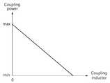
도 10은 일실시예에 따른 커플링부에 커플링 인덕터가 사용되는 경우의 커플링 전력을 나타낸 그래프이다.10 is a graph illustrating coupling power when a coupling inductor is used in a coupling unit, according to an exemplary embodiment.
커플링부는 커플링 인덕터를 이용하여 출력 전력 신호를 커플링 할 수 있다. 커플링은 일반적으로 RF분야에서 신호를 커플링하는 방식으로 이루어질 수 있다. 도 10을 참조하면, 커플링 인덕터의 값이 클수록 커플링 되는 출력 전력 신호의 크기가 작아다. 여기서, 커플링 인덕터의 값은 커플링 인덕터의 인덕턴스를 의미한다. 커플링 인덕터 값과 출력 전력 신호의 크기는 반비례하는 관계이다. 커플링부는 적절한 출력 전력 신호의 크기를 커플링하기 위해, 커플링 인덕터 값을 결정할 수 있다.
The coupling unit may couple the output power signal using a coupling inductor. Coupling can generally be accomplished by coupling signals in the RF field. Referring to FIG. 10, the larger the value of the coupling inductor, the smaller the magnitude of the coupled output power signal. Here, the value of the coupling inductor means the inductance of the coupling inductor. The coupling inductor value is inversely related to the magnitude of the output power signal. The coupling portion may determine the coupling inductor value to couple the magnitude of the appropriate output power signal.
도 11은 일실시예에 따른 전력 제한부의 동작을 설명하기 위한 도면이다.11 is a diagram for describing an operation of a power limiting unit, according to an exemplary embodiment.
전력 제한부는 출력 전력 신호의 크기를 제한할 수 있다. 출력 전력 신호에는 반송파(1110) 및 로드 모듈레이션 신호(1120)가 포함되어 있다. 반송파(1110)는 공진 주파수를 반송 주파수로 하는 신호이고, 로드 모듈레이션 신호(1120)는 타겟 디바이스의 임피던스 변화에 따라 주파수 또는 위상이 변화된 신호를 의미한다.The power limiter may limit the magnitude of the output power signal. The output power signal includes a
전력 제한부는 반송파(1110)의 크기와 로드 모듈레이션 신호의 크기의 차이(1130)만큼 출력 전력 신호의 크기를 제한할 수 있다. 전력 제한부는 power limiter, clipper 등을 통하여 출력 전력 신호의 크기를 제한할 수 있다. 전력 제한부는 기 설정된 크기만큼 임의로 출력 전력 신호의 크기를 제한할 수도 있다.
The power limiter may limit the size of the output power signal by the
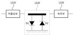
도 12는 일실시예에 따른 전력 제한부의 일 예를 나타낸 도면이다.12 is a diagram illustrating an example of a power limiting unit according to an embodiment.
전력 제한부(1220)는 커플링부(1210)에서 커플링 된 출력 전력 신호를 입력 신호로 수신 수 있다. 전력 제한부(1220)는 다이오드(D1,D2)를 이용하여, 출력 전력 신호의 크기를 제한할 수 있다. 다이오드(D1, D2)는 클리퍼(Clipper)로 동작할 수 있다. 전력 제한부(1220)는 출력 전력 신호의 크기가 제한된 신호를 출력할 수 있다. 출력 전력 신호의 크기가 제한된 신호는 복조부(1230)에서 위상 보상 후, 복조될 수 있다.
The
도 13은 도 12의 일실시예에 따른 전력 제한부의 입력 전력과 출력전력을 나타낸 그래프이다.FIG. 13 is a graph illustrating input power and output power of the power limiter according to the exemplary embodiment of FIG. 12.
전력 제한부(1220)에 입력되는 출력 전력 신호는 소정의 크기가 넘어가는 구간에서는 출력 값이 일정한 값으로 제한된다. 전력 제한부(1220)는 로드 모듈레이션 신호의 크기의 최대값보다 큰 값들에 대해서는 출력 값을 일정한 값으로 제한할 수도 있다.
The output power signal input to the
도 14 내지 도 16은 일실시예에 따른 복조부(260)의 일 예를 나타낸 도면이다.14 to 16 are diagrams showing an example of a
도 14를 참조하면, 복조부(260)는 위상 합성부(1410), LPF(1420), 증폭기(1430) 및 비교부(1440)를 포함할 수 있다.Referring to FIG. 14, the
위상 합성부(1410)는 전력 신호 검출부(240)에서 검출된 출력 전력 신호와, 반송파와 동일한 위상의 신호를 합성할 수 있다. 반송파는 소스 공진기와 타겟 공진기 간의 공진 주파수를 반송 주파수로 하는 신호이다. 반송파와 동일한 위상의 신호는 사인파형 또는 코사인파형의 신호일 수 있다. 위상 합성부(1410)는 검출된 출력 전력 신호의 부분 중, 반송파와 동일한 위상에 해당하는 부분은 합성 신호의 크기를 크게 출력하고, 반송파와 반대 위상에 해당하는 부분은 합성 신호의 크기를 작게 출력할 수 있다. 또한, 위상 합성부(1410)는 검출된 출력 전력 신호와, 반송파에 대해 특정 위상만큼 차이가 나는 신호를 합성할 수도 있다. 반송파와 동일한 위상의 신호뿐만 아니라, 45도, 90도, 180도와 같이 반송파에 대해 특정 위상만큼 차이가 나는 신호도 합성될 수 있다. 또한, 위상 합성부(1410)는 검출된 출력 전력 신호와 반송파에 대해 0도에서 360도 사이에서 특정 위상만큼 차이가 나는 신호를 합성할 수도 있다.The
LPF(1420)는 저역 통과 필터(Low Pass Filter)로서, 합성 신호에서 노이즈 또는 하모닉 성분이 적은 신호 대역을 필터링할 수 있다. 증폭기(1420)는 필터링된 신호의 크기를 소정의 크기만큼 증폭할 수 있다. 비교부(1440)는 합성 신호와 기준(reference) 신호를 비교하여 "하이" 또는 "로우" 값을 출력할 수 있다. 이때, 기준 신호는 합성 신호의 크기 중 최소값을 가지는 신호의 레벨을 의미할 수 있다. 기준 신호는 제어부(270)에서 제공될 수 있고, 합성 신호마다 그 값이 다를 수 있다.The
복조부(260)는 비교부(1440)에서 출력된 "하이" 또는 "로우" 값에 기초하여, 타겟 디바이스의 메시지를 복조할 수 있다. 제어부(270)도 비교부(1440)에서 출력된 "하이" 또는 "로우" 값에 기초하여, 타겟 디바이스의 메시지를 복조할 수도 있다.
The
도 15를 참조하면, 복조부(260)는 분배부(1510), 동위상 합성부(1520), 반대위상 합성부(1530), 위상 변환부(1540), 비교부(1550)를 포함할 수 있다.Referring to FIG. 15, the
분배부(1510)는 검출된 출력 전력 신호를 제1 신호 및 제2 신호로 분배할 수 있다. 이때, 제1 신호 및 제2 신호는 검출된 출력 전력 신호와 동일한 위상을 가지는 신호로서, 크기만 다른 신호이다.The
동위상 합성부(1520)는 주파수 발생부(210)에서 발생한 반송파와 동일한 위상의 신호를 제1 신호와 합성하여, 제1 합성신호를 생성할 수 있다. 반송파와 동일한 위상의 신호는 위상 변환부(1540)에서 반송파에 대해 0도의 위상변환이 이루어진 경우를 의미한다.The in-
반대위상 합성부(1530)는 주파수 발생부(210)에서 발생한 반송파와 반대 위상의 신호를 제2 신호와 합성하여, 제2 합성 신호를 생성할 수 있다. 반송파와 반대 위상의 신호는 위상 변환부(1540)에서 반송파에 대해 90도의 위상변환이 이루어진 경우를 의미한다. 예를 들면, 반송파가 사인파인 경우에, 반송파에 대해 90도의 위상변환이 이루어지면, 코사인파가 된다.The
제1 신호와 제2 신호는 동일한 위상을 가지는 신호이므로, 동위상 합성부(1520) 또는 반대위상 합성부(1530) 중 적어도 어느 하나에서는 합성 신호로 출력될 수 있다. 합성 신호는 반송파와 주파수 및 위상이 동기되므로, 복조부(260)는 합성 신호를 복조함으로써, 타겟 디바이스의 메시지를 복조할 수 있게 된다. 즉, 동위상 합성부(1520) 및 반대위상 합성부(1530)를 통하여 제1 신호 및 제2 신호의 위상이 반송파의 위상과 동일해지도록 보상될 수 있다.Since the first signal and the second signal have the same phase, at least one of the in-
비교부(1550)는 제1 합성 신호의 크기와 제2 합성 신호의 크기를 비교하여 "하이" 또는 "로우" 값을 출력할 수 있다. 복조부(260) 또는 제어부(270)는 "하이" 또는 "로우" 값에 기초하여, 타겟 디바이스의 메시지를 복조할 수 있다.The
또한, 제어부(270)는 제1 합성 신호의 크기와 제2 합성 신호의 크기를 비교하여, 타겟 디바이스의 메시지를 바로 복조할 수도 있다.
In addition, the
도 16을 참조하면, 복조부(260)는 분배부(1610), 동위상 합성부(1620), 반대위상 합성부(1630), 위상 변환부(1640), 비교부(1650, 1660)를 포함할 수 있다. 도 15와 다르게, 비교부(1650)가 동위상 합성부(1620)의 합성신호를 기준신호와 비교하고, 비교부(1660)가 반대위상 합성부(1630)의 합성신호를 기준신호와 비교한다는 점에서 차이가 있다.Referring to FIG. 16, the
분배부(1610)는 검출된 출력 전력 신호를 제1 신호 및 제2 신호로 분배할 수 있다. 이때, 제1 신호 및 제2 신호는 서로 동일한 위상 및 크기를 가지는 신호이다.The
동위상 합성부(1620)는 주파수 발생부(210)에서 발생한 반송파와 동일한 위상의 신호를 제1 신호와 합성하여, 제1 합성신호를 생성할 수 있다. 반송파와 동일한 위상의 신호는 위상 변환부(1640)에서 반송파에 대해 0도의 위상변환이 이루어진 경우를 의미한다.The in-
반대위상 합성부(1630)는 주파수 발생부(210)에서 발생한 반송파와 반대 위상의 신호를 제2 신호와 합성하여, 제2 합성 신호를 생성할 수 있다. 반송파와 반대 위상의 신호는 위상 변환부(1640)에서 반송파에 대해 90도의 위상변환이 이루어진 경우를 의미한다. 예를 들면, 반송파가 사인파인 경우에, 반송파에 대해 90도의 위상변환이 이루어지면, 코사인파가 된다.The
비교부(1650)는 제1 합성신호와 기준신호를 비교하여 "하이" 또는 "로우" 값을 출력할 수 있다. 이때, 기준 신호는 제1 합성 신호의 크기 중 최소값을 가지는 신호의 레벨을 의미할 수 있다. 기준 신호는 제어부(270)에서 제공될 수 있고, 제1 합성 신호와 제2 합성 신호에서 그 값이 다를 수 있다.The
비교부(1660)는 제2 합성신호와 기준신호를 비교하여 "하이" 또는 "로우" 값을 출력할 수 있다. 이때, 기준 신호는 제1 합성 신호의 크기 중 최소값을 가지는 신호의 레벨을 의미할 수 있다. 기준 신호는 제어부(270)에서 제공될 수 있고, 제1 합성 신호와 제2 합성 신호에서 그 값이 다를 수 있다.The
복조부(260)는 비교부(1650)에서 출력된 "하이" 또는 "로우" 값과 비교부(1660)에서 출력된 "하이" 또는 "로우" 값을 동기화된 시간 별로 비교하여, 타겟 디바이스의 메시지를 복조할 수 있다. 또한, 제어부(270)도 비교부(1650)에서 출력된 "하이" 또는 "로우" 값과 비교부(1660)에서 출력된 "하이" 또는 "로우" 값을 프로세서의 클락 마다 비교하여, 타겟 디바이스의 메시지를 복조할 수 있다.
The
도 17은 다른 일실시예에 따른 무선 전력을 이용한 데이터 통신 장치의 블록도이다.17 is a block diagram of a data communication apparatus using wireless power according to another exemplary embodiment.
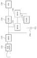
도 17을 참조하면, 무선 전력을 이용한 데이터 통신 장치는 타겟 공진부(1710), 정류부(1720), DC/DC 컨버터(1730, 1770), 부하(1740), 변조부(1750), 제어부(1760)를 포함한다.Referring to FIG. 17, a data communication apparatus using wireless power includes a
타겟 공진부(1710)는 소스 공진기와 타겟 공진기간의 마그네틱 커플링을 통하여, 소스 공진기로부터 반송파를 수신한다. 반송파는 공진 주파수를 반송 주파수로 하여 전력이 실린 신호이다. 타겟 공진부(1710)는 타겟 디바이스의 제어부를 구동시키는 데 필요한 웨이크 업 전력을 수신할 수 있다. 정류부(1720)는 교류 신호를 직류 신호로 정류한다. 반송파는 교류 신호이므로, 정류부(1720)는 반송파를 직류 신호로 정류할 수 있다. DC/DC 컨버터(1730)는 부하(1740)에서 필요로 하는 전압레벨 또는 전류레벨로 직류 신호를 변환할 수 있다.The
변조부(1750)는 반송파 및 소스 디바이스와 타겟 디바이스간의 임피던스 미스매칭(mismatching)에 기초하여 메시지를 변조한다. 임피던스 미스매칭이 발생하면, 타겟 디바이스의 반사 전력이 커지게 된다. 즉, 임피던스 미스매칭을 의도적으로 조절하여, 타겟 디바이스의 반사 전력을 변화시킬 수 있고, 메시지를 변조할 수 있다. 이러한 메시지 변조를 로드 모듈레이션이라고 부른다. 임피던스 미스매칭과 맵핑되는 데이터는 제어부(1760)에서 제공될 수 있다.The
제어부(1760)는 타겟 디바이스의 임피던스를 변경할 수 있다. 따라서, 제어부(1760)는 소스 디바이스와 타겟 디바이스 간의 임피던스 미스매칭을 제어할 수 있다.The
제어부(1760)는 가변 부하 또는 액티브 로드(active load)에 흐르는 전류의 온/오프 또는 전류량을 제어함으로써, 타겟 디바이스의 임피던스를 변경할 수 있다. 타겟 디바이스에 가변 부하 또는 액티브 로드가 연결되어 전류가 흐르는 경우, 타겟 디바이스의 임피던스는 변경될 수 있다. 제어부(1760)는 가변 부하의 크기를 변경하거나 가변 부하에 흐르는 전류량을 제어할 수 있다.The
또한, 제어부(1760)는 가변 부하로 동작하는 전류 소스를 통하여 타겟 디바이스의 임피던스를 변경할 수 있다. 제어부(1760)는 전류 소스(current source)에 흐르는 전류량을 제어하여 타겟 디바이스의 임피던스를 변경할 수 있다.In addition, the
또한, 제어부(1760)는 타겟 디바이스의 부하(1740)에 연결된 스위치의 온/오프를 이용하여, 타겟 디바이스의 임피던스를 변경할 수 있다. 제어부(1760)는 부하(1740)와 DC/DC 컨버터(1730) 간의 연결에 따라 타겟 디바이스의 임피던스를 변경할 수 있다.In addition, the
DC/DC 컨버터(1770)는 제어부(1760)의 동작에 필요한 전압레벨 또는 전류레벨로 직류 신호를 변환한다. 제어부(1760)의 동작이 멈추지 않도록 캐패시터(1780)에 예비 전력이 저장될 수 있다.
The DC / DC converter 1770 converts the DC signal into a voltage level or a current level necessary for the operation of the
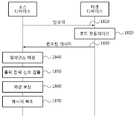
도 18은 일실시예에 따른 무선 전력을 이용한 데이터 통신 방법의 흐름도이다.18 is a flowchart of a data communication method using wireless power, according to an embodiment.
1810단계에서, 소스 디바이스는 소스 공진기와 타겟 공진기 간의 공진 주파수를 반송 주파수로 하여, 반송파를 전송할 수 있다. 반송파는 전력 신호의 형태로 타겟 디바이스에 전달될 수 있다. 반송파는 소스 공진기와 타겟 공진기 간의 마그네틱 커플링을 통하여 타겟 디바이스에 전달될 수 있다.In
1820단계에서, 타겟 디바이스는 임피던스를 변경함으로써, 소스 디바이스와 타겟 디바이스의 임피던스 미스매칭을 발생시킬 수 있다. 타겟 디바이스는 임피던스 미스매칭을 이용하여 메시지를 변조할 수 있고, 이를 로드 모듈레이션이라고 한다. 이때, 타겟 디바이스는 공진 주파수를 반송 주파수로 하여 메시지를 변조할 수 있다. 그런데, 임피던스 미스매칭 또는 소스 디바이스와 타겟 디바이스의 위치관계에 따라, 로드 모듈레이션 신호의 위상 또는 주파수가 변경될 수 있다.In
1830단계에서, 소스 디바이스는 로드 모듈레이션에 의해 변조된 메시지를 수신할 수 있다. 변조된 메시지의 수신여부는 소스 디바이스에서 출력되는 출력 전력 신호의 크기 변화를 통해 감지될 수 있다. 타겟 디바이스의 임피던스가 변하게 되면, 소스 디바이스에서 출력하는 전력 신호의 크기가 변하기 때문이다.In
1840단계에서, 소스 디바이스는 타겟 디바이스의 변화된 임피던스에 대해, 임피던스 매칭을 수행할 수 있다.In
1850단계에서, 소스 디바이스는 임피던스 매칭 수행과정에서 출력되는 출력 전력 신호를 검출하여, 로드 모듈레이션 신호와 반송파를 검출할 수 있다. 소스 디바이스는 공진 주파수의 교류신호의 커플링을 통해 출력 전력 신호를 검출할 수 있다.In
또한, 소스 디바이스는 커플링 된 출력 전력 신호의 크기를 제한 할 수 있다. 소스 디바이스는 출력 전력 신호의 크기를 반송파의 크기와 로드 모듈레이션 신호의 크기의 차이만큼 제한할 수 있다. 또한, 소스 디바이스는 기 설정된 시간 동안 출력 전력 신호를 검출하지 않도록 제어할 수도 있고, 검출된 출력 전력 신호를 복조하지 않을 수도 있다.In addition, the source device can limit the magnitude of the coupled output power signal. The source device may limit the magnitude of the output power signal by the difference between the magnitude of the carrier and the magnitude of the load modulation signal. In addition, the source device may control not to detect the output power signal for a preset time or may not demodulate the detected output power signal.
1860단계에서, 소스 디바이스는 검출된 출력 전력 신호의 위상을 보상할 수 있다. 검출된 출력 전력 신호에는 로드 모듈레이션 신호가 포함될 수 있다. 로드 모듈레이션 신호는 반송파와 주파수 또는 위상이 다르기 때문에 반송파와 동일한 위상으로 보상할 필요가 있다. 소스 디바이스는 반송파와 동일한 위상 또는 반대위상 또는 특정한 위상으로 변환된 신호를 검출된 출력 전력 신호와 합성함으로써, 검출된 출력 전력 신호의 위상을 보상할 수 있다.In
1870단계에서, 소스 디바이스는 위상이 보상된 합성 신호에 기초하여 타겟 디바이스의 메시지를 복조할 수 있다. 이때, 소스 디바이스는 비교부를 이용할 수 있다. 비교부는 상기 합성 신호와 기준 신호를 비교하여, "하이" 또는 "로우" 값을 출력할 수 있다. 이때, 기준 신호는 합성 신호의 크기 중 최소값을 가지는 신호의 레벨을 의미할 수 있다. 소스 디바이스는 "하이" 또는 "로우" 값에 기초하여 메시지를 복조할 수 있다.In
도 19는 일 실시예에 따른 전기 자동차(electric vehicle) 충전 시스템을 나타낸다.19 illustrates an electric vehicle charging system according to one embodiment.
도 19을 참조하면, 전기 자동차 충전 시스템(1900)은 소스 시스템(1910), 소스 공진기(1920), 타겟 공진기(1930), 타겟 시스템(1940) 및 전기 자동차용 배터리(1950)을 포함한다.Referring to FIG. 19, an electric
전기 자동차 충전 시스템(1900)은 도 1의 무선 전력 전송 시스템과 유사한 구조를 가진다. 전기 자동차 충전 시스템(1900)은 소스 시스템(1910) 및 소스 공진기(1920)로 구성되는 소스를 포함한다. 또한, 전기 자동차 충전 시스템(1900)은 타겟 공진기(1930) 및 타겟 시스템(1940)로 구성되는 타겟을 포함한다.The electric
이때, 소스 시스템(1910)은 도 1의 소스 디바이스(110)와 같이, AC/DC 컨버터, 파워 검출기(Power Detecter), 전력변환부, 제어 및 통신부를 포함할 수 있다. 이때, 타겟 시스템(1940)은 도 1의 타겟 디바이스(190)와 같이, 정류부, DC/DC 컨버터, 스위치부, 충전부 및 제어 및 통신부를 포함할 수 있다.In this case, like the
전기 자동차용 배터리(1950)는 타겟 시스템(1940)에 의해 충전 될 수 있다.The
전기 자동차 충전 시스템(1900)은 수 KHz~수십 MHz의 공진 주파수를 사용할 수 있다.The electric
소스 시스템(1910)은 충전 차량의 종류, 배터리의 용량, 배터리의 충전 상태에 따라 전력을 생성하고, 생성된 전력을 타겟 시스템(1940)으로 공급할 수 있다.The
소스 시스템(1910)은 소스 공진기(1920) 및 타겟 공진기(1930)의 정렬(alignment)를 맞추기 위한 제어를 수행할 수 있다. 예를 들어, 소스 시스템(1910)의 제어부는 소스 공진기(1920)와 타겟 공진기(1930)의 정렬(alignment)이 맞지 않은 경우, 타겟 시스템(1940)으로 메시지를 전송하여 정렬(alignment)을 제어할 수 있다.The
이때, 정렬(alignment)이 맞지 않은 경우란, 타겟 공진기(1930)의 위치가 마그네틱 레조넌스(magnetic resonance)가 최대로 일어나기 위한 위치에 있지 않은 경우 일 수 있다. 즉, 차량이 정확하게 정차되지 않은 경우, 소스 시스템(1910)은 차량의 위치를 조정하도록 유도함으로써, 소스 공진기(1920)와 타겟 공진기(1930)의 정렬(alignment)이 맞도록 유도할 수 있다.In this case, the misalignment may be a case where the position of the
소스 시스템(1910)과 타겟 시스템(1940)은 통신을 통해, 차량의 식별자를 송수신할 수 있고, 각종 메시지를 주고 받을 수 있다.The
도 1 내지 도 18에서 설명된 내용들은 전기 자동차 충전 시스템(1900)에 적용될 수 있다. 다만, 전기 자동차 충전 시스템(1900)은 수 KHz~수십 MHz의 공진 주파수를 사용하고, 전기 자동차용 배터리(1950)를 충전하기 위해 수십 watt이상의 전력 전송을 수행할 수 있다.
1 to 18 may be applied to the electric
도 20 및 도 21는 일 실시예에 따른 무선 전력 수신 장치 및 무선 전력 전송 장치가 탑재될 수 있는 어플리케이션들을 나타낸다.20 and 21 illustrate applications in which a wireless power receiver and a wireless power transmitter according to an embodiment may be mounted.
도 20을 참조하면, (a)는 패드(2010)와 모바일 단말(2020) 간의 무선 전력 충전을 나타내고, (b)는 패드들(2030, 2040)과 보청기들(2050, 2060) 간의 무선 전력 충전을 나타낸다.Referring to FIG. 20, (a) illustrates wireless power charging between the
일 실시예에 따른 무선 전력 전송 장치는 패드(2010)에 탑재될 수 있다. 일 실시예에 따른 무선 전력 수신 장치는 모바일 단말(2020)에 탑재될 수 있다. 이때, 패드(2010)는 하나의 모바일 단말(2020)을 충전할 수 있다.The wireless power transmitter according to an embodiment may be mounted on the
일 실시예에 따른 2개의 무선 전력 전송 장치는 제1 패드(2030) 및 제2 패드(2040) 각각에 탑재될 수 있다. 보청기(2050)는 왼쪽 귀의 보청기를 나타내고, 보청기(2060)는 오른쪽 귀의 보청기를 나타낸다. 일 실시예에 따른 2개의 무선 전력 수신 장치는 보청기(2050) 및 보청기(2060) 각각에 탑재될 수 있다.Two wireless power transmitters according to an embodiment may be mounted on each of the
도 21를 참조하면, (a)는 인체에 삽입된 전자기기(2110)와 모바일 단말(2120) 간의 무선 전력 충전을 나타내고, (b)는 보청기(2130)와 모바일 단말(2140) 간의 무선 전력 충전을 나타낸다.Referring to FIG. 21, (a) illustrates wireless power charging between the
일 실시예에 따른 무선 전력 전송 장치 및 일 실시예에 따른 무선 전력 수신 장치는 모바일 단말(2120)에 탑재될 수 있다. 일 실시예에 따른 무선 전력 수신 장치는 인체에 삽입된 전자기기(2110)에 탑재될 수 있다. 인체에 삽입된 전자기기(2110)는 모바일 단말(2120)로부터 전력을 수신하여 충전될 수 있다.The wireless power transmitter and the wireless power receiver according to an embodiment may be mounted in the
일 실시예에 따른 무선 전력 전송 장치 및 일 실시예에 따른 무선 전력 수신 장치는 모바일 단말(2140)에 탑재될 수 있다. 일 실시예에 따른 무선 전력 수신 장치는 보청기(2130)에 탑재될 수 있다. 보청기(2130)는 모바일 단말(2140)로부터 전력을 수신하여 충전될 수 있다. 보청기(2130)뿐만 아니라, 블루투스 이어폰과 같은 저전력 전자기기들도 모바일 단말(2140)로부터 전력을 수신하여 충전될 수 있다.
The wireless power transmitter and the wireless power receiver according to an embodiment may be mounted in the
도 22은 일 실시예에 따른 무선 전력 전송 장치 및 무선 전력 수신 장치의 구성 예를 나타낸다.22 illustrates an example of a configuration of a wireless power transmitter and a wireless power receiver according to an embodiment.
도 22에서 무선 전력 전송 장치(2210)는 도 20의 제1 패드(2030) 및 제2 패드(2040) 각각에 탑재 될 수 있다. 또한, 도 22에서 무선 전력 전송 장치(2210)는 도 21의 모바일 단말(2140)에 탑재될 수 있다.In FIG. 22, the
도 22에서 무선 전력 수신 장치(2220)는 보청기(2050) 및 보청기(2060) 각각에 탑재될 수 있다.In FIG. 22, the
무선 전력 전송 장치(2210)는 도 1의 무선 전력 전송 장치(110)와 유사한 구성을 포함할 수 있다. 즉, 무선 전력 전송 장치(2210)는 마그네틱 커플링을 이용하여 전력을 전송하기 위한 구성을 포함할 수 있다.The
도 22에서 통신 및 트래킹부(2211)는 무선 전력 수신 장치(2220)와 통신을 수행하고, 무선 전력 전송 효율을 유지하기 위한 임피던스 제어 및 공진주파수 제어를 수행할 수 있다. 즉, 통신 및 트래킹부(2211)는 도 1의 115와 유사한 기능을 수행할 수 있다.In FIG. 22, the communication and
무선 전력 수신 장치(2220)는 도 1의 무선 전력 수신 장치(120)와 유사한 구성을 포함할 수 있다. 즉, 무선 전력 수신 장치(2220)는 전력을 무선으로 수신하여 배터리를 충전하기 위한 구성을 포함한다. 무선 전력 수신 장치(2220)는 타겟 공진기, 정류기, DC/DC 컨버터, 충전 회로를 포함할 수 있다. 또한, 무선 전력 수신 장치(2220)는 통신 및 제어부(2223)를 포함할 수 있다.The
통신 및 제어부(2223)는 무선 전력 전송 장치(2210)와 통신을 수행하고, 과전압 및 과전류 보호를 위한 동작을 수행할 수 있다.The communication and
무선 전력 수신 장치(2220)는 청각기기 회로(2221)를 포함할 수 있다. 청각기기 회로(2221)는 배터리에 의해 충전될 수 있다. 청각기기 회로(2221)는 마이크, 아날로그-디지털 변환기, 프로세서, 디지탈-아날로그 변환기 및 리시버를 포함할 수 있다. 즉, 청각기기 회로(2221)는 보청기와 동일한 구성을 포함할 수 있다.The
실시예에 따른 방법은 다양한 컴퓨터 수단을 통하여 수행될 수 있는 프로그램 명령 형태로 구현되어 컴퓨터 판독 가능 매체에 기록될 수 있다. 상기 컴퓨터 판독 가능 매체는 프로그램 명령, 데이터 파일, 데이터 구조 등을 단독으로 또는 조합하여 포함할 수 있다. 상기 매체에 기록되는 프로그램 명령은 실시예를 위하여 특별히 설계되고 구성된 것들이거나 컴퓨터 소프트웨어 당업자에게 공지되어 사용 가능한 것일 수도 있다. 컴퓨터 판독 가능 기록 매체의 예에는 하드 디스크, 플로피 디스크 및 자기 테이프와 같은 자기 매체(magnetic media), CD-ROM, DVD와 같은 광기록 매체(optical media), 플롭티컬 디스크(floptical disk)와 같은 자기-광 매체(magnet-optical media), 및 롬(ROM), 램(RAM), 플래시 메모리 등과 같은 프로그램 명령을 저장하고 수행하도록 특별히 구성된 하드웨어 장치가 포함된다. 프로그램 명령의 예에는 컴파일러에 의해 만들어지는 것과 같은 기계어 코드뿐만 아니라 인터프리터 등을 사용해서 컴퓨터에 의해서 실행될 수 있는 고급 언어 코드를 포함한다. 상기된 하드웨어 장치는 실시예의 동작을 수행하기 위해 하나 이상의 소프트웨어 모듈로서 작동하도록 구성될 수 있으며, 그 역도 마찬가지이다.The method according to the embodiment may be embodied in the form of program instructions that can be executed by various computer means and recorded in a computer readable medium. The computer readable medium may include program instructions, data files, data structures, etc. alone or in combination. The program instructions recorded on the media may be those specially designed and constructed for the purposes of the embodiments, or they may be of the kind well-known and available to those having skill in the computer software arts. Examples of computer-readable recording media include magnetic media such as hard disks, floppy disks, and magnetic tape, optical media such as CD-ROMs, DVDs, and magnetic disks, such as floppy disks. Magnet-optical media, and hardware devices specifically configured to store and execute program instructions, such as ROM, RAM, flash memory, and the like. Examples of program instructions include not only machine code generated by a compiler, but also high-level language code that can be executed by a computer using an interpreter or the like. The hardware device described above may be configured to operate as one or more software modules to perform the operations of the embodiments, and vice versa.
이상과 같이 실시예들이 비록 한정된 실시예와 도면에 의해 설명되었으나, 해당 기술분야에서 통상의 지식을 가진 자라면 상기의 기재로부터 다양한 수정 및 변형이 가능하다. 예를 들어, 설명된 기술들이 설명된 방법과 다른 순서로 수행되거나, 및/또는 설명된 시스템, 구조, 장치, 회로 등의 구성요소들이 설명된 방법과 다른 형태로 결합 또는 조합되거나, 다른 구성요소 또는 균등물에 의하여 대치되거나 치환되더라도 적절한 결과가 달성될 수 있다.Although the embodiments have been described by the limited embodiments and the drawings as described above, various modifications and variations are possible to those skilled in the art from the above description. For example, the described techniques may be performed in a different order than the described method, and / or components of the described systems, structures, devices, circuits, etc. may be combined or combined in a different form than the described method, or other components. Or even if replaced or substituted by equivalents, an appropriate result can be achieved.
그러므로, 다른 구현들, 다른 실시예들 및 특허청구범위와 균등한 것들도 후술하는 특허청구범위의 범위에 속한다.Therefore, other implementations, other embodiments, and equivalents to the claims are within the scope of the claims that follow.
Claims (24)
Translated fromKorean상기 검출된 출력 전력 신호의 일부 및 반송파와 위상이 동일한 신호를 합성하여 제1 합성 신호를 생성하고, 상기 검출된 출력 전력 신호의 나머지 및 반송파의 위상이 변환된 신호를 합성하여 제2 합성 신호를 생성하며, 상기 제1 합성 신호 및 상기 제2 합성 신호를 기초로 상기 타겟 디바이스의 메시지를 복조하는 복조부;
소스 공진기의 크기를 고려하여, 상기 반송파의 위상을 제어하는 제어부; 및
타겟 공진기와 상기 소스 공진기 간의 마그네틱 커플링을 통하여 상기 타겟 디바이스로 상기 반송파를 전송하고, 상기 타겟 디바이스로부터 상기 메시지를 수신하는 소스 공진부
를 포함하는 무선 전력을 이용한 데이터 통신 장치.A power signal detector configured to detect an output power signal of a power amplifier that outputs a power signal corresponding to a change in impedance of the target device;
A part of the detected output power signal and a signal having the same phase as the carrier are synthesized to generate a first synthesized signal, and the second synthesized signal is synthesized by synthesizing the remaining signal of the detected output power signal and the phase shifted carrier. A demodulator for generating and demodulating a message of the target device based on the first composite signal and the second composite signal;
A controller which controls the phase of the carrier in consideration of the size of a source resonator; And
A source resonator for transmitting the carrier to the target device through the magnetic coupling between the target resonator and the source resonator, and receiving the message from the target device
Data communication device using a wireless power comprising a.
상기 출력 전력 신호의 크기의 변화에 기초하여, 상기 타겟 디바이스의 임피던스 변화를 감지하는 감지부
를 더 포함하는 무선 전력을 이용한 데이터 통신 장치The method of claim 1,
A detector configured to detect a change in impedance of the target device based on a change in the magnitude of the output power signal
Data communication device using a wireless power further comprising
상기 전력 신호 검출부는
커플링 저항, 커플링 인덕터 및 커플링 캐패시터 중 적어도 하나를 이용하여, 상기 출력 전력 신호를 커플링하는 커플링부
를 포함하는 무선 전력을 이용한 데이터 통신 장치.The method of claim 1,
The power signal detector
A coupling unit configured to couple the output power signal by using at least one of a coupling resistor, a coupling inductor, and a coupling capacitor
Data communication device using a wireless power comprising a.
상기 커플링부는
상기 전력 증폭기와 상기 소스 공진기 사이에 연결된 전력 전송 라인(power line) 또는 그라운드 라인(ground line)으로부터 상기 출력 전력 신호를 커플링하는
무선 전력을 이용한 데이터 통신 장치.The method of claim 3,
The coupling part
Coupling the output power signal from a power line or a ground line coupled between the power amplifier and the source resonator
Data communication device using wireless power.
상기 반송파는
상기 소스 공진기의 공진 주파수를 반송 주파수로 하는
무선 전력을 이용한 데이터 통신 장치.The method of claim 3,
The carrier is
The resonant frequency of the source resonator is a carrier frequency
Data communication device using wireless power.
상기 전력 신호 검출부는
상기 반송파의 크기의 최대값과 상기 타겟 디바이스의 임피던스 변화에 대응하여 생성된 출력 전력 신호의 크기의 최대값의 차이만큼 상기 커플링 된 상기 출력 전력 신호의 크기를 제한하는 전력 제한부
를 포함하는 무선 전력을 이용한 데이터 통신 장치.The method of claim 5,
The power signal detector
A power limiter configured to limit the magnitude of the coupled output power signal by a difference between a maximum value of the magnitude of the carrier and a maximum value of the magnitude of the output power signal generated in response to a change in impedance of the target device;
Data communication device using a wireless power comprising a.
상기 전력 신호 검출부는
상기 소스 공진기가 상기 타겟 디바이스를 웨이크 업(wak--up) 시키는 웨이크 업 신호를 전송하는 동안에는 상기 커플링 된 상기 출력 전력 신호의 수신을 제어하는 수신 제어부
를 포함하는 무선 전력을 이용한 데이터 통신 장치.The method of claim 3,
The power signal detector
A reception control unit controlling reception of the coupled output power signal while the source resonator transmits a wake-up signal for waking up the target device;
Data communication device using a wireless power comprising a.
상기 복조부는
상기 검출된 출력 전력 신호를 상기 일부 및 상기 나머지로 분배하는 분배부;
상기 제1 합성신호를 생성하는 동위상 합성부; 및
상기 제2 합성 신호를 생성하는 반대위상 합성부
를 포함하는 무선 전력을 이용한 데이터 통신 장치.The method of claim 1,
The demodulation unit
A distribution unit for distributing the detected output power signal to the part and the remainder;
An in-phase synthesizer for generating the first synthesized signal; And
Inverse phase synthesis unit for generating the second synthesis signal
Data communication device using a wireless power comprising a.
상기 복조부는
상기 제1 합성신호의 크기와 상기 제2 합성신호의 크기를 비교하여 "하이" 또는 "로우" 값을 출력하는 비교부
를 더 포함하는 무선 전력을 이용한 데이터 통신 장치.The method of claim 10,
The demodulation unit
A comparator for comparing the magnitude of the first composite signal with the magnitude of the second composite signal and outputting a "high" or "low" value
Data communication device using a wireless power further comprising.
상기 복조부는
상기 제1 합성신호의 크기와 제1 기준 신호를 비교하여 "하이" 또는 "로우" 값을 출력하는 제1 비교부; 및
상기 제2 합성신호의 크기와 제2 기준 신호를 비교하여 "하이" 또는 "로우" 값을 출력하는 제2 비교부
를 더 포함하는 무선 전력을 이용한 데이터 통신 장치.The method of claim 10,
The demodulation unit
A first comparison unit comparing the magnitude of the first composite signal with a first reference signal and outputting a “high” or “low” value; And
A second comparator for comparing a magnitude of the second composite signal with a second reference signal and outputting a “high” or “low” value;
Data communication device using a wireless power further comprising.
상기 복조부는
상기 제1 비교부에서 출력된 상기 "하이" 또는 "로우" 값과, 상기 제2 비교부에서 출력된 상기 "하이" 또는 "로우" 값을 동기화된 시간 별로 비교하여, 상기 타겟 디바이스의 메시지를 복조하는
무선 전력을 이용한 데이터 통신 장치.The method of claim 12,
The demodulation unit
The message of the target device is compared by comparing the "high" or "low" value output from the first comparator with the "high" or "low" value output from the second comparator for each synchronized time. Demodulated
Data communication device using wireless power.
상기 반송파 및 소스 디바이스와 타겟 디바이스간의 임피던스 미스매칭(mismatching)에 기초하여 메시지를 변조하는 변조부; 및
상기 타겟 디바이스의 임피던스를 변경함으로써, 상기 임피던스 미스매칭을 제어하는 제어부
를 포함하고,
상기 변조된 메시지는 상기 소스 디바이스가 복조 단계를 수행함으로써 상기 소스 디바이스에 의해 복조되고,
상기 복조 단계는 상기 소스 디바이스의 전력 증폭기의 출력 전력 신호의 일부 및 상기 반송파와 위상이 동일한 신호를 합성하여 제1 합성 신호를 생성하는 단계, 상기 출력 전력 신호의 나머지 및 상기 반송파의 위상이 변환된 신호를 합성하여 제2 합성 신호를 생성하는 단계, 및 상기 제1 합성 신호 및 상기 제2 합성 신호를 기초로 상기 변조된 메시지를 복조하는 단계를 포함하는, 무선 전력을 이용한 데이터 통신 장치.A target resonator configured to receive a carrier wave from the source resonator through magnetic coupling between a source resonator and a target resonant period;
A modulator for modulating a message based on impedance mismatching between the carrier and a source device and a target device; And
Control unit for controlling the impedance mismatching by changing the impedance of the target device
Including,
The modulated message is demodulated by the source device by the source device performing a demodulation step,
In the demodulating step, a part of an output power signal of a power amplifier of the source device and a signal having a phase in phase with the carrier are synthesized to generate a first synthesized signal, and the remainder of the output power signal and the phase of the carrier are converted. Synthesizing a signal to generate a second composite signal; and demodulating the modulated message based on the first composite signal and the second composite signal.
상기 제어부는
가변 부하에 흐르는 전류의 온/오프를 제어함으로써, 상기 타겟 디바이스의 임피던스 및 위상을 변경하는
무선 전력을 이용한 데이터 통신 장치.The method of claim 14,
The control unit
By controlling the on / off of the current flowing in the variable load to change the impedance and phase of the target device
Data communication device using wireless power.
상기 제어부는
가변 부하로 동작하는 전류 소스를 통하여 상기 타겟 디바이스의 임피던스를 변경하는
무선 전력을 이용한 데이터 통신 장치.The method of claim 14,
The control unit
Altering the impedance of the target device through a current source operating with a variable load
Data communication device using wireless power.
상기 제어부는
상기 타겟 디바이스의 부하에 연결된 스위치의 온/오프를 이용하여, 상기 타겟 디바이스의 임피던스 및 위상을 변경하는
무선 전력을 이용한 데이터 통신 장치.The method of claim 14,
The control unit
By changing the impedance and phase of the target device by using the on / off of the switch connected to the load of the target device
Data communication device using wireless power.
상기 검출된 출력 전력 신호의 일부 및 반송파와 위상이 동일한 신호를 합성하여 제1 합성 신호를 생성하고, 상기 검출된 출력 전력 신호의 나머지 및 반송파의 위상이 변환된 신호를 합성하여 제2 합성 신호를 생성하며, 상기 제1 합성 신호 및 상기 제2 합성 신호를 기초로 상기 타겟 디바이스의 메시지를 복조하는 단계;
소스 공진기의 크기를 고려하여, 기 설정된 기준에 따라 상기 반송파의 위상을 제어하는 단계; 및
타겟 공진기와 상기 소스 공진기 간의 마그네틱 커플링을 통하여 상기 타겟 디바이스로 상기 반송파를 전송하고, 상기 타겟 디바이스로부터 상기 메시지를 수신하는 단계
를 포함하는 무선 전력을 이용한 데이터 통신 방법.Detecting an output power signal of a power amplifier that outputs a power signal corresponding to a change in impedance of the target device;
A part of the detected output power signal and a signal having the same phase as the carrier are synthesized to generate a first synthesized signal, and the second synthesized signal is synthesized by synthesizing the remaining signal of the detected output power signal and the phase shifted carrier. Generating and demodulating a message of the target device based on the first composite signal and the second composite signal;
Controlling the phase of the carrier according to a preset reference in consideration of the size of a source resonator; And
Transmitting the carrier to the target device through a magnetic coupling between a target resonator and the source resonator and receiving the message from the target device
Data communication method using a wireless power comprising a.
상기 출력 전력 신호를 검출하는 단계는
커플링 저항, 커플링 인덕터 및 커플링 캐패시터 중 적어도 하나를 이용하여, 상기 출력 전력 신호를 커플링하는 단계
를 포함하는 무선 전력을 이용한 데이터 통신 방법.The method of claim 18,
Detecting the output power signal
Coupling the output power signal using at least one of a coupling resistor, a coupling inductor, and a coupling capacitor.
Data communication method using a wireless power comprising a.
상기 출력 전력 신호를 검출하는 단계는
상기 반송파의 크기의 최대값과 상기 타겟 디바이스의 임피던스 변화에 대응하여 생성된 출력 전력 신호의 크기의 최대값의 차이만큼 상기 커플링 된 상기 출력 전력 신호의 크기를 제한하는 단계
를 포함하는 무선 전력을 이용한 데이터 통신 방법.The method of claim 19,
Detecting the output power signal
Limiting the magnitude of the coupled output power signal by a difference between the maximum value of the magnitude of the carrier and the maximum value of the magnitude of the output power signal generated in response to the impedance change of the target device;
Data communication method using a wireless power comprising a.
상기 반송파 및 소스 디바이스와 타겟 디바이스간의 임피던스 미스매칭(mismatching)에 기초하여 메시지를 변조하는 단계; 및
상기 타겟 디바이스의 임피던스를 변경함으로써, 상기 임피던스 미스매칭을 제어하는 단계
를 포함하고,
상기 변조된 메시지는 상기 소스 디바이스가 복조 단계를 수행함으로써 상기 소스 디바이스에 의해 복조되고,
상기 복조 단계는 상기 소스 디바이스의 전력 증폭기의 출력 전력 신호의 일부 및 상기 반송파와 위상이 동일한 신호를 합성하여 제1 합성 신호를 생성하는 단계, 상기 출력 전력 신호의 나머지 및 상기 반송파의 위상이 변환된 신호를 합성하여 제2 합성 신호를 생성하는 단계, 및 상기 제1 합성 신호 및 상기 제2 합성 신호를 기초로 상기 변조된 메시지를 복조하는 단계를 포함하는, 무선 전력을 이용한 데이터 통신 방법.Receiving a carrier from the source resonator through magnetic coupling between a source resonator and a target resonant period;
Modulating a message based on the impedance mismatching between the carrier and a source device and a target device; And
Controlling the impedance mismatching by changing an impedance of the target device
Including,
The modulated message is demodulated by the source device by the source device performing a demodulation step,
In the demodulating step, a part of an output power signal of a power amplifier of the source device and a signal having a phase in phase with the carrier are synthesized to generate a first synthesized signal, and the remainder of the output power signal and the phase of the carrier are converted. Synthesizing a signal to generate a second composite signal; and demodulating the modulated message based on the first composite signal and the second composite signal.
상기 제어하는 단계는
가변 부하에 흐르는 전류의 온/오프를 제어함으로써, 상기 타겟 디바이스의 부하에 흐르는 전류를 제어하여 상기 타겟 디바이스의 임피던스를 변경하는
무선 전력을 이용한 데이터 통신 방법.The method of claim 23, wherein
The controlling step
By controlling the on / off of the current flowing in the variable load, controlling the current flowing in the load of the target device to change the impedance of the target device
Data communication method using wireless power.
Priority Applications (1)
| Application Number | Priority Date | Filing Date | Title |
|---|---|---|---|
| KR1020120055768AKR102012688B1 (en) | 2011-05-31 | 2012-05-25 | Apparatus and method for data communication using wireless power |
Applications Claiming Priority (3)
| Application Number | Priority Date | Filing Date | Title |
|---|---|---|---|
| KR1020110052179 | 2011-05-31 | ||
| KR20110052179 | 2011-05-31 | ||
| KR1020120055768AKR102012688B1 (en) | 2011-05-31 | 2012-05-25 | Apparatus and method for data communication using wireless power |
Publications (2)
| Publication Number | Publication Date |
|---|---|
| KR20120134032A KR20120134032A (en) | 2012-12-11 |
| KR102012688B1true KR102012688B1 (en) | 2019-08-26 |
Family
ID=47261658
Family Applications (1)
| Application Number | Title | Priority Date | Filing Date |
|---|---|---|---|
| KR1020120055768AActiveKR102012688B1 (en) | 2011-05-31 | 2012-05-25 | Apparatus and method for data communication using wireless power |
Country Status (2)
| Country | Link |
|---|---|
| US (1) | US9160417B2 (en) |
| KR (1) | KR102012688B1 (en) |
Families Citing this family (61)
| Publication number | Priority date | Publication date | Assignee | Title |
|---|---|---|---|---|
| KR101925405B1 (en)* | 2012-04-12 | 2018-12-05 | 삼성전자주식회사 | Apparatus and method for wireless energy reception and apparatus wireless energy transmission |
| US10965164B2 (en) | 2012-07-06 | 2021-03-30 | Energous Corporation | Systems and methods of wirelessly delivering power to a receiver device |
| US10992187B2 (en) | 2012-07-06 | 2021-04-27 | Energous Corporation | System and methods of using electromagnetic waves to wirelessly deliver power to electronic devices |
| US11502551B2 (en) | 2012-07-06 | 2022-11-15 | Energous Corporation | Wirelessly charging multiple wireless-power receivers using different subsets of an antenna array to focus energy at different locations |
| US12057715B2 (en) | 2012-07-06 | 2024-08-06 | Energous Corporation | Systems and methods of wirelessly delivering power to a wireless-power receiver device in response to a change of orientation of the wireless-power receiver device |
| US9867062B1 (en) | 2014-07-21 | 2018-01-09 | Energous Corporation | System and methods for using a remote server to authorize a receiving device that has requested wireless power and to determine whether another receiving device should request wireless power in a wireless power transmission system |
| US10256657B2 (en) | 2015-12-24 | 2019-04-09 | Energous Corporation | Antenna having coaxial structure for near field wireless power charging |
| US10992185B2 (en) | 2012-07-06 | 2021-04-27 | Energous Corporation | Systems and methods of using electromagnetic waves to wirelessly deliver power to game controllers |
| US9825674B1 (en) | 2014-05-23 | 2017-11-21 | Energous Corporation | Enhanced transmitter that selects configurations of antenna elements for performing wireless power transmission and receiving functions |
| US10312715B2 (en) | 2015-09-16 | 2019-06-04 | Energous Corporation | Systems and methods for wireless power charging |
| US9287827B2 (en)* | 2012-09-06 | 2016-03-15 | Qualcomm Incorporated | System and method to demodulate a load modulated signal |
| JP2014212662A (en) | 2013-04-19 | 2014-11-13 | キヤノン株式会社 | Transmission device and control method therefor, power transmission system |
| CN105264744B (en)* | 2013-06-05 | 2018-03-06 | 三星电子株式会社 | Wireless power receiving unit and method of generating load change for detecting same in wireless charging |
| US20150091523A1 (en)* | 2013-10-02 | 2015-04-02 | Mediatek Singapore Pte. Ltd. | Wireless charger system that has variable power / adaptive load modulation |
| EP3322101B1 (en) | 2014-06-19 | 2019-09-11 | Koninklijke Philips N.V. | Wireless inductive power transfer |
| US10383126B2 (en)* | 2014-09-05 | 2019-08-13 | University Of Washington | Power transmission using wireless communication signals |
| KR101604722B1 (en)* | 2014-11-12 | 2016-03-22 | 순천향대학교 산학협력단 | Hybrid coupler using intentional mismatching of branch line |
| US11710321B2 (en) | 2015-09-16 | 2023-07-25 | Energous Corporation | Systems and methods of object detection in wireless power charging systems |
| US10778041B2 (en) | 2015-09-16 | 2020-09-15 | Energous Corporation | Systems and methods for generating power waves in a wireless power transmission system |
| US10734717B2 (en) | 2015-10-13 | 2020-08-04 | Energous Corporation | 3D ceramic mold antenna |
| TWI586118B (en)* | 2015-10-22 | 2017-06-01 | 國立勤益科技大學 | A charging and communication system |
| KR102475095B1 (en)* | 2015-10-26 | 2022-12-08 | 주식회사 위츠 | Wireless power transmitter |
| US10063108B1 (en) | 2015-11-02 | 2018-08-28 | Energous Corporation | Stamped three-dimensional antenna |
| US10038332B1 (en) | 2015-12-24 | 2018-07-31 | Energous Corporation | Systems and methods of wireless power charging through multiple receiving devices |
| US10079515B2 (en) | 2016-12-12 | 2018-09-18 | Energous Corporation | Near-field RF charging pad with multi-band antenna element with adaptive loading to efficiently charge an electronic device at any position on the pad |
| US11863001B2 (en) | 2015-12-24 | 2024-01-02 | Energous Corporation | Near-field antenna for wireless power transmission with antenna elements that follow meandering patterns |
| US20180048162A1 (en)* | 2016-08-15 | 2018-02-15 | Qualcomm Incorporated | Methods and apparatus for signaling using harmonic and subharmonic modulation |
| US10923954B2 (en) | 2016-11-03 | 2021-02-16 | Energous Corporation | Wireless power receiver with a synchronous rectifier |
| KR102185600B1 (en) | 2016-12-12 | 2020-12-03 | 에너저스 코포레이션 | A method of selectively activating antenna zones of a near field charging pad to maximize transmitted wireless power |
| US10439442B2 (en) | 2017-01-24 | 2019-10-08 | Energous Corporation | Microstrip antennas for wireless power transmitters |
| US10680319B2 (en) | 2017-01-06 | 2020-06-09 | Energous Corporation | Devices and methods for reducing mutual coupling effects in wireless power transmission systems |
| US11011942B2 (en) | 2017-03-30 | 2021-05-18 | Energous Corporation | Flat antennas having two or more resonant frequencies for use in wireless power transmission systems |
| US11462949B2 (en) | 2017-05-16 | 2022-10-04 | Wireless electrical Grid LAN, WiGL Inc | Wireless charging method and system |
| US12074460B2 (en) | 2017-05-16 | 2024-08-27 | Wireless Electrical Grid Lan, Wigl Inc. | Rechargeable wireless power bank and method of using |
| US12074452B2 (en) | 2017-05-16 | 2024-08-27 | Wireless Electrical Grid Lan, Wigl Inc. | Networked wireless charging system |
| US10848853B2 (en) | 2017-06-23 | 2020-11-24 | Energous Corporation | Systems, methods, and devices for utilizing a wire of a sound-producing device as an antenna for receipt of wirelessly delivered power |
| US11342798B2 (en) | 2017-10-30 | 2022-05-24 | Energous Corporation | Systems and methods for managing coexistence of wireless-power signals and data signals operating in a same frequency band |
| US10615647B2 (en) | 2018-02-02 | 2020-04-07 | Energous Corporation | Systems and methods for detecting wireless power receivers and other objects at a near-field charging pad |
| DE102018212957B3 (en) | 2018-08-02 | 2020-01-02 | Fraunhofer-Gesellschaft zur Förderung der angewandten Forschung e.V. | TRANSFER OF DATA FROM ONE USER TERMINAL TO ANOTHER DEVICE |
| US11437735B2 (en) | 2018-11-14 | 2022-09-06 | Energous Corporation | Systems for receiving electromagnetic energy using antennas that are minimally affected by the presence of the human body |
| US11539243B2 (en) | 2019-01-28 | 2022-12-27 | Energous Corporation | Systems and methods for miniaturized antenna for wireless power transmissions |
| DE102019201152B3 (en) | 2019-01-30 | 2020-06-18 | Fraunhofer-Gesellschaft zur Förderung der angewandten Forschung e.V. | Bi-directional configuration of sensor nodes with a mobile phone without expansion |
| EP3921945A1 (en) | 2019-02-06 | 2021-12-15 | Energous Corporation | Systems and methods of estimating optimal phases to use for individual antennas in an antenna array |
| US12155231B2 (en) | 2019-04-09 | 2024-11-26 | Energous Corporation | Asymmetric spiral antennas for wireless power transmission and reception |
| DE102020109640A1 (en)* | 2019-04-11 | 2020-10-15 | Apple Inc. | WIRELESS POWER SYSTEM WITH IN-BAND COMMUNICATIONS |
| US10998776B2 (en) | 2019-04-11 | 2021-05-04 | Apple Inc. | Wireless power system with in-band communications |
| DE102019206836A1 (en) | 2019-05-10 | 2020-11-12 | Fraunhofer-Gesellschaft zur Förderung der angewandten Forschung e.V. | Efficient communication for configuring sensor nodes |
| WO2021055898A1 (en) | 2019-09-20 | 2021-03-25 | Energous Corporation | Systems and methods for machine learning based foreign object detection for wireless power transmission |
| US11381118B2 (en) | 2019-09-20 | 2022-07-05 | Energous Corporation | Systems and methods for machine learning based foreign object detection for wireless power transmission |
| WO2021055899A1 (en) | 2019-09-20 | 2021-03-25 | Energous Corporation | Systems and methods of protecting wireless power receivers using multiple rectifiers and establishing in-band communications using multiple rectifiers |
| WO2021055901A1 (en) | 2019-09-20 | 2021-03-25 | Energous Corporation | Asymmetric spiral antennas with parasitic elements for wireless power transmission |
| CN114731061A (en) | 2019-09-20 | 2022-07-08 | 艾诺格思公司 | Classifying and detecting foreign objects using a power amplifier controller integrated circuit in a wireless power transmission system |
| US11355966B2 (en) | 2019-12-13 | 2022-06-07 | Energous Corporation | Charging pad with guiding contours to align an electronic device on the charging pad and efficiently transfer near-field radio-frequency energy to the electronic device |
| US10985617B1 (en) | 2019-12-31 | 2021-04-20 | Energous Corporation | System for wirelessly transmitting energy at a near-field distance without using beam-forming control |
| US11799324B2 (en) | 2020-04-13 | 2023-10-24 | Energous Corporation | Wireless-power transmitting device for creating a uniform near-field charging area |
| US11469629B2 (en) | 2020-08-12 | 2022-10-11 | Energous Corporation | Systems and methods for secure wireless transmission of power using unidirectional communication signals from a wireless-power-receiving device |
| US12306285B2 (en) | 2020-12-01 | 2025-05-20 | Energous Corporation | Systems and methods for using one or more sensors to detect and classify objects in a keep-out zone of a wireless-power transmission field, and antennas with integrated sensor arrangements |
| EP4322373A4 (en) | 2021-09-28 | 2024-11-20 | Samsung Electronics Co., Ltd. | Wireless power transmission device including impedance matching circuit, and wireless power transmission method |
| US11916398B2 (en) | 2021-12-29 | 2024-02-27 | Energous Corporation | Small form-factor devices with integrated and modular harvesting receivers, and shelving-mounted wireless-power transmitters for use therewith |
| US12142939B2 (en) | 2022-05-13 | 2024-11-12 | Energous Corporation | Integrated wireless-power-transmission platform designed to operate in multiple bands, and multi-band antennas for use therewith |
| CN117526585B (en)* | 2024-01-03 | 2024-03-29 | 成都市易冲半导体有限公司 | Phase demodulation circuit, wireless power transmitting end and wireless charging system |
Citations (2)
| Publication number | Priority date | Publication date | Assignee | Title |
|---|---|---|---|---|
| US20100217553A1 (en)* | 2009-01-22 | 2010-08-26 | Qualcomm Incorporated | Impedance change detection in wireless power transmission |
| US20110065398A1 (en)* | 2009-09-14 | 2011-03-17 | Convenientpower Hk Ltd | Universal demodulation and modulation for data communication in wireless power transfer |
Family Cites Families (16)
| Publication number | Priority date | Publication date | Assignee | Title |
|---|---|---|---|---|
| JPH1014139A (en) | 1996-06-17 | 1998-01-16 | Nec Corp | Power transmission device |
| US8447234B2 (en)* | 2006-01-18 | 2013-05-21 | Qualcomm Incorporated | Method and system for powering an electronic device via a wireless link |
| US7952322B2 (en)* | 2006-01-31 | 2011-05-31 | Mojo Mobility, Inc. | Inductive power source and charging system |
| JP2007336788A (en) | 2006-06-19 | 2007-12-27 | Dainippon Printing Co Ltd | Non-contact power feeding system, power feeding device, and power receiving device |
| US20090284369A1 (en) | 2008-05-13 | 2009-11-19 | Qualcomm Incorporated | Transmit power control for a wireless charging system |
| US8772973B2 (en)* | 2008-09-27 | 2014-07-08 | Witricity Corporation | Integrated resonator-shield structures |
| US20100277121A1 (en)* | 2008-09-27 | 2010-11-04 | Hall Katherine L | Wireless energy transfer between a source and a vehicle |
| US8497658B2 (en) | 2009-01-22 | 2013-07-30 | Qualcomm Incorporated | Adaptive power control for wireless charging of devices |
| US8452235B2 (en) | 2009-03-28 | 2013-05-28 | Qualcomm, Incorporated | Tracking receiver devices with wireless power systems, apparatuses, and methods |
| US8928284B2 (en) | 2009-09-10 | 2015-01-06 | Qualcomm Incorporated | Variable wireless power transmission |
| US8541974B2 (en) | 2009-09-17 | 2013-09-24 | Qualcomm Incorporated | Movable magnetically resonant antenna for wireless charging |
| KR101730824B1 (en)* | 2009-11-30 | 2017-04-27 | 삼성전자주식회사 | Wireless power transceiver and wireless power system |
| US20110217926A1 (en)* | 2010-03-03 | 2011-09-08 | Qualcomm Incorporated | Reverse link signaling via impedance modulation |
| JP2011223739A (en)* | 2010-04-09 | 2011-11-04 | Sony Corp | Power supply device, power reception device, and wireless power supply system |
| US9013069B2 (en)* | 2010-10-08 | 2015-04-21 | Panasonic Intellectual Property Management Co., Ltd. | Power generation system and power generating unit |
| US9306634B2 (en)* | 2011-03-01 | 2016-04-05 | Qualcomm Incorporated | Waking up a wireless power transmitter from beacon mode |
- 2012
- 2012-05-25KRKR1020120055768Apatent/KR102012688B1/enactiveActive
- 2012-05-29USUS13/482,133patent/US9160417B2/ennot_activeExpired - Fee Related
Patent Citations (2)
| Publication number | Priority date | Publication date | Assignee | Title |
|---|---|---|---|---|
| US20100217553A1 (en)* | 2009-01-22 | 2010-08-26 | Qualcomm Incorporated | Impedance change detection in wireless power transmission |
| US20110065398A1 (en)* | 2009-09-14 | 2011-03-17 | Convenientpower Hk Ltd | Universal demodulation and modulation for data communication in wireless power transfer |
Also Published As
| Publication number | Publication date |
|---|---|
| KR20120134032A (en) | 2012-12-11 |
| US9160417B2 (en) | 2015-10-13 |
| US20120307873A1 (en) | 2012-12-06 |
Similar Documents
| Publication | Publication Date | Title |
|---|---|---|
| KR102012688B1 (en) | Apparatus and method for data communication using wireless power | |
| KR102022350B1 (en) | Apparatus and method for communication using wireless power | |
| EP2769479B1 (en) | Wireless power carrier-synchronous communication | |
| KR102012684B1 (en) | Apparatus and method for communication using wireless power | |
| KR102013688B1 (en) | System and method for communication in wireless power supply systems | |
| US9461481B2 (en) | Systems and methods for controlling output power of a wireless power transmitter | |
| EP2745412B1 (en) | Wireless power receiver with multiple receiver coils | |
| US9450455B2 (en) | Magnetic resonance power transmitter and magnetic resonance power receiver | |
| US8111041B2 (en) | Power transmission control device, power reception control device, non-contact power transmission system, power transmission device, power reception device, and electronic instrument | |
| US20130249306A1 (en) | Wireless power transmission system and method for increasing coupling efficiency by adjusting resonant frequency | |
| JP6446194B2 (en) | Wireless power receiving apparatus, receiver circuit thereof, and method for controlling wireless power receiving apparatus | |
| US20120155344A1 (en) | Out-of-band communication on harmonics of the primary carrier in a wireless power system | |
| JP2014180201A (en) | Wireless charging system, devices, and methods | |
| EP3479457B1 (en) | Apparatus and method for wireless power charging of subsequent receiver | |
| CN104769812A (en) | Method for communication and power control of wireless power transmitter in magnetic resonance wireless power transmission system | |
| KR20130055199A (en) | Apparatus and method for controlling amount of charging current for wireless power receiver | |
| JP2015008628A (en) | Adaptive power control for wireless charging | |
| WO2008112977A1 (en) | Multiple frequency transmitter, receiver, and systems thereof | |
| CN102983635A (en) | Devices, systems and methods for performing communication using wireless power | |
| CN104604082A (en) | Push-pull driver for generating a signal for wireless power transfer | |
| CN103036825A (en) | Apparatus and method for envelope detection | |
| Lee et al. | A reconfigurable bidirectional wireless power and full-duplex data transceiver IC for wearable biomedical applications | |
| CN101938288B (en) | Signal processing method and device applied to responder and responder | |
| US8611111B2 (en) | Resonance power generator | |
| KR20200088584A (en) | Wireless transmit receive system for transmits data and power at the same time |
Legal Events
| Date | Code | Title | Description |
|---|---|---|---|
| PA0109 | Patent application | Patent event code:PA01091R01D Comment text:Patent Application Patent event date:20120525 | |
| PG1501 | Laying open of application | ||
| PA0201 | Request for examination | Patent event code:PA02012R01D Patent event date:20170525 Comment text:Request for Examination of Application Patent event code:PA02011R01I Patent event date:20120525 Comment text:Patent Application | |
| E902 | Notification of reason for refusal | ||
| PE0902 | Notice of grounds for rejection | Comment text:Notification of reason for refusal Patent event date:20181214 Patent event code:PE09021S01D | |
| E701 | Decision to grant or registration of patent right | ||
| PE0701 | Decision of registration | Patent event code:PE07011S01D Comment text:Decision to Grant Registration Patent event date:20190626 | |
| GRNT | Written decision to grant | ||
| PR0701 | Registration of establishment | Comment text:Registration of Establishment Patent event date:20190820 Patent event code:PR07011E01D | |
| PR1002 | Payment of registration fee | Payment date:20190820 End annual number:3 Start annual number:1 | |
| PG1601 | Publication of registration | ||
| PR1001 | Payment of annual fee | Payment date:20220923 Start annual number:4 End annual number:4 | |
| PR1001 | Payment of annual fee | Payment date:20230821 Start annual number:5 End annual number:5 | |
| PR1001 | Payment of annual fee | Payment date:20240819 Start annual number:6 End annual number:6 |