KR102011457B1 - Mobile terminal and control method thereof - Google Patents
Mobile terminal and control method thereofDownload PDFInfo
- Publication number
- KR102011457B1 KR102011457B1KR1020130042398AKR20130042398AKR102011457B1KR 102011457 B1KR102011457 B1KR 102011457B1KR 1020130042398 AKR1020130042398 AKR 1020130042398AKR 20130042398 AKR20130042398 AKR 20130042398AKR 102011457 B1KR102011457 B1KR 102011457B1
- Authority
- KR
- South Korea
- Prior art keywords
- mobile terminal
- destination
- signal
- vehicle navigation
- display unit
- Prior art date
- Legal status (The legal status is an assumption and is not a legal conclusion. Google has not performed a legal analysis and makes no representation as to the accuracy of the status listed.)
- Active
Links
Images


Classifications
- G—PHYSICS
- G01—MEASURING; TESTING
- G01C—MEASURING DISTANCES, LEVELS OR BEARINGS; SURVEYING; NAVIGATION; GYROSCOPIC INSTRUMENTS; PHOTOGRAMMETRY OR VIDEOGRAMMETRY
- G01C21/00—Navigation; Navigational instruments not provided for in groups G01C1/00 - G01C19/00
- G01C21/26—Navigation; Navigational instruments not provided for in groups G01C1/00 - G01C19/00 specially adapted for navigation in a road network
- G01C21/34—Route searching; Route guidance
- G01C21/36—Input/output arrangements for on-board computers
- G01C21/3626—Details of the output of route guidance instructions
- G01C21/3632—Guidance using simplified or iconic instructions, e.g. using arrows
- G—PHYSICS
- G01—MEASURING; TESTING
- G01C—MEASURING DISTANCES, LEVELS OR BEARINGS; SURVEYING; NAVIGATION; GYROSCOPIC INSTRUMENTS; PHOTOGRAMMETRY OR VIDEOGRAMMETRY
- G01C21/00—Navigation; Navigational instruments not provided for in groups G01C1/00 - G01C19/00
- G01C21/26—Navigation; Navigational instruments not provided for in groups G01C1/00 - G01C19/00 specially adapted for navigation in a road network
- G01C21/34—Route searching; Route guidance
- G01C21/36—Input/output arrangements for on-board computers
- G01C21/3626—Details of the output of route guidance instructions
- G01C21/3661—Guidance output on an external device, e.g. car radio
- G—PHYSICS
- G04—HOROLOGY
- G04G—ELECTRONIC TIME-PIECES
- G04G21/00—Input or output devices integrated in time-pieces
- G04G21/02—Detectors of external physical values, e.g. temperature
- G—PHYSICS
- G04—HOROLOGY
- G04G—ELECTRONIC TIME-PIECES
- G04G21/00—Input or output devices integrated in time-pieces
- G04G21/06—Input or output devices integrated in time-pieces using voice
- G—PHYSICS
- G01—MEASURING; TESTING
- G01C—MEASURING DISTANCES, LEVELS OR BEARINGS; SURVEYING; NAVIGATION; GYROSCOPIC INSTRUMENTS; PHOTOGRAMMETRY OR VIDEOGRAMMETRY
- G01C21/00—Navigation; Navigational instruments not provided for in groups G01C1/00 - G01C19/00
- G01C21/26—Navigation; Navigational instruments not provided for in groups G01C1/00 - G01C19/00 specially adapted for navigation in a road network
- G01C21/34—Route searching; Route guidance
- G01C21/36—Input/output arrangements for on-board computers
- G01C21/3667—Display of a road map
- H—ELECTRICITY
- H04—ELECTRIC COMMUNICATION TECHNIQUE
- H04B—TRANSMISSION
- H04B1/00—Details of transmission systems, not covered by a single one of groups H04B3/00 - H04B13/00; Details of transmission systems not characterised by the medium used for transmission
- H04B1/38—Transceivers, i.e. devices in which transmitter and receiver form a structural unit and in which at least one part is used for functions of transmitting and receiving
- H04B1/3827—Portable transceivers
- H04B1/385—Transceivers carried on the body, e.g. in helmets
- H04B2001/3861—Transceivers carried on the body, e.g. in helmets carried in a hand or on fingers
- H—ELECTRICITY
- H04—ELECTRIC COMMUNICATION TECHNIQUE
- H04B—TRANSMISSION
- H04B1/00—Details of transmission systems, not covered by a single one of groups H04B3/00 - H04B13/00; Details of transmission systems not characterised by the medium used for transmission
- H04B1/38—Transceivers, i.e. devices in which transmitter and receiver form a structural unit and in which at least one part is used for functions of transmitting and receiving
- H04B1/3827—Portable transceivers
- H04B1/385—Transceivers carried on the body, e.g. in helmets
- H04B2001/3866—Transceivers carried on the body, e.g. in helmets carried on the head
Landscapes
- Engineering & Computer Science (AREA)
- Radar, Positioning & Navigation (AREA)
- Remote Sensing (AREA)
- Automation & Control Theory (AREA)
- Physics & Mathematics (AREA)
- General Physics & Mathematics (AREA)
- Navigation (AREA)
- Telephone Function (AREA)
Abstract
Translated fromKoreanDescription
Translated fromKorean본 발명은 이동 단말기에 관한 것으로, 좀 더 구체적으로 네비게이션(navigation) 기능을 제공하는 이동 단말기 및 그것의 제어 방법에 관한 것이다.TECHNICAL FIELD The present invention relates to a mobile terminal, and more particularly, to a mobile terminal providing a navigation function and a control method thereof.
단말기(terminal)는 이동 가능여부에 따라 이동 단말기(mobile/portable terminal) 및 고정 단말기(stationary terminal)로 나뉠 수 있다. 다시 이동 단말기는 사용자의 직접 휴대 가능 여부에 따라 휴대(형) 단말기(handheld terminal) 및 거치형 단말기(vehicle mount terminal)로 나뉠 수 있다.Terminal is movable It may be divided into a mobile terminal (portable terminal) and a stationary terminal according to whether or not. The mobile terminal may be further classified into a handheld terminal and a vehicle mount terminal according to whether a user can directly carry it.
이와 같은 단말기는 기능이 다양화됨에 따라, 예를 들어, 사진이나 동영상의 촬영, 음악이나 동영상 파일의 재생, 게임, 방송의 수신 등의 복합적인 기능들을 갖춘 멀티미디어 기기(Multimedia player) 형태로 구현되고 있다. 나아가 단말기의 기능 지지 및 증대를 위해, 단말기의 구조적인 부분 및 소프트웨어적인 부분을 개량하는 것이 고려될 수 있다.As the functions are diversified, for example, the terminal is implemented in the form of a multimedia player having complex functions such as taking a picture or video, playing a music or video file, playing a game or receiving a broadcast. have. Further, in order to support and increase the function of the terminal, it may be considered to improve the structural part and the software part of the terminal.
이러한 개량에 힘입어, 이동 단말기는 설정한 목적지로의 길 안내를 제공하는 네비게이션(navigation) 기능을 제공할 수 있게 되었다. 그러나 실시간으로 도보 길 안내를 제공하는데는 어려움이 있다. 또한, 사용자가 길 안내를 받기 위해서는 항상 길 안내 제공 화면을 주시해야 하는 문제점이 있다.Thanks to this improvement, the mobile terminal can provide a navigation function that provides a route guidance to a set destination. However, there is a difficulty in providing walking directions in real time. In addition, there is a problem that the user must always watch the road guidance providing screen to receive the road guidance.
본 발명의 목적은 목적지로의 진행 방향을 제공할 수 있고, 차량 네비게이션과도 연동 가능한 이동 단말기 및 그것의 제어 방법을 제공하는 데 있다.It is an object of the present invention to provide a mobile terminal capable of providing a direction of travel to a destination and interworking with vehicle navigation and a control method thereof.
본 발명의 일 실시 예에 따른 네비게이션 기능을 제공하는 이동 단말기는, 목적지를 입력받는 입력부; 상기 이동 단말기의 현재 위치를 산출하기 위한 신호를 수신하는 수신부; 상기 이동 단말기의 현재 위치에 따라 상기 목적지에 도달하기 위한 진행 방향을 실시간으로 산출하는 제어부; 상기 산출한 진행 방향을 나타내는 화살표를 출력하는 디스플레이부; 및 상기 목적지와 상기 이동 단말기의 현재 위치를 사전에 설정한 차량 네비게이션 장치로 전송하는 통신부;를 포함하며, 상기 차량 네비게이션 장치는 상기 이동 단말기의 현재 위치를 출발지로 하여 상기 목적지로 길 안내 할 수 있다.A mobile terminal providing a navigation function according to an embodiment of the present invention includes an input unit for receiving a destination; A receiver which receives a signal for calculating a current position of the mobile terminal; A controller configured to calculate a moving direction for reaching the destination in real time according to a current position of the mobile terminal; A display unit which outputs an arrow indicating the calculated moving direction; And a communication unit configured to transmit the destination and the current location of the mobile terminal to a preset vehicle navigation device, wherein the vehicle navigation device may guide the road to the destination using the current location of the mobile terminal as a starting point. .
실시 예에 있어서, 상기 입력부는, 상기 목적지를 음성신호로 입력받을 수 있다.In an embodiment, the input unit may receive the destination as a voice signal.
실시 예에 있어서, 상기 제어부는, 상기 이동 단말기의 현재 위치에 따라 상기 목적지에 도달하기 위한 진행 방향이 변하는 경우, 상기 변화된 진행 방향을 나타내는 화살표가 출력되도록 상기 디스플레이부를 제어할 수 있다.The control unit may control the display unit to output an arrow indicating the changed moving direction when the moving direction for reaching the destination is changed according to the current position of the mobile terminal.
실시 예에 있어서, 상기 제어부는, 상기 산출한 진행 방향을 나타내는 사전에 설정한 신호가 출력되도록 제어할 수 있다.In an embodiment, the control unit may control to output a preset signal indicating the calculated travel direction.
실시 예에 있어서, 상기 통신부는, 상기 차량 네비게이션 장치와 사전에 설정한 프로토콜을 이용하여 데이터를 송수신할 수 있다.In an embodiment, the communication unit may transmit / receive data with the vehicle navigation apparatus using a preset protocol.
본 발명의 일 실시 예에 따른 네비게이션 기능을 제공하는 이동 단말기의 제어 방법은, (a) 목적지를 입력받는 단계; (b) 상기 이동 단말기의 현재 위치를 산출하기 위한 신호를 수신하는 단계; (c) 상기 이동 단말기의 현재 위치를 산출하고, 상기 산출한 이동 단말기의 현재 위치에 따라 상기 목적지에 도달하기 위한 진행 방향을 실시간으로 산출하는 단계; (d) 상기 산출한 진행 방향을 나타내는 화살표를 디스플레이부에 출력하는 단계; 및 (e) 상기 목적지와 상기 이동 단말기의 현재 위치를 사전에 설정한 차량 네비게이션 장치로 전송하는 단계;를 포함하며, 상기 차량 네비게이션 장치는 상기 이동 단말기의 현재 위치를 출발지로 하여 상기 목적지로 길 안내 할 수 있다.According to one or more exemplary embodiments, a control method of a mobile terminal providing a navigation function includes: (a) receiving a destination; (b) receiving a signal for calculating a current position of the mobile terminal; (c) calculating a current position of the mobile terminal and calculating in real time a direction for reaching the destination according to the calculated current position of the mobile terminal; (d) outputting an arrow indicating the calculated traveling direction on a display unit; And (e) transmitting the destination and the current location of the mobile terminal to a preset vehicle navigation device, wherein the vehicle navigation device uses the current location of the mobile terminal as a starting point to guide the route to the destination. can do.
실시 예에 있어서, 상기 (a) 단계는, 상기 목적지를 음성신호로 입력받는 단계를 포함할 수있다.In an embodiment, the step (a) may include receiving the destination as a voice signal.
실시 예에 있어서, 상기 (d) 단계는, 상기 이동 단말기의 현재 위치에 따라 상기 목적지에 도달하기 위한 진행 방향이 변하는 경우, 상기 변화된 진행 방향을 나타내는 화살표를 상기 디스플레이부에 출력하는 단계를 포함할 수 있다.In an embodiment, the step (d) may include outputting an arrow indicating the changed moving direction to the display unit when the moving direction for reaching the destination is changed according to a current position of the mobile terminal. Can be.
실시 예에 있어서, 상기 (d) 단계는, 상기 산출한 진행 방향을 나타내는 사전에 설정한 신호를 출력하는 단계를 포함할 수 있다.In an embodiment, the step (d) may include outputting a preset signal indicating the calculated heading direction.
실시 예에 있어서, 상기 (e) 단계는, 상기 차량 네비게이션 장치와 사전에 설정한 프로토콜을 이용하여 데이터를 송수신하는 단계를 포함할 수 있다.In an embodiment, the step (e) may include transmitting / receiving data using a protocol set in advance with the vehicle navigation apparatus.
본 발명에 의하면, 목적지로의 진행 방향을 진행 방향이 바뀌는 경우 제공받을 수 있다. 이에 따라, 단말기의 전력이 절약될 수 있고 사용자는 지속적으로 모니터를 주시할 필요 없이 안전하게 목적지로 이동할 수 있다.According to the present invention, the direction of travel to the destination may be provided when the direction of travel changes. Accordingly, the power of the terminal can be saved and the user can safely move to the destination without having to constantly watch the monitor.
또한, 차량 네비게이션과의 연동으로 끊김없이 길 안내를 제공받을 수 있으며 운전시 안전하게 목적지를 변경할 수 있다. 이때, 단말기의 마이크를 이용하므로 차량 마이크 이용시보다 음성 인식률이 높아지게 된다.In addition, it can be provided with a road guidance seamlessly in conjunction with the vehicle navigation and can safely change the destination when driving. In this case, since the microphone of the terminal is used, the speech recognition rate is higher than that of the vehicle microphone.
그 결과, 사용자의 편의가 향상될 수 있다.As a result, the user's convenience can be improved.
도 1은 본 명세서에 개시된 일 실시 예에 따른 이동 단말기를 나타내는 블록도이다.
도 2a 및 도 2b는 본 발명에 따른 이동 단말기가 동작 가능한 통신 시스템의 개념도이다.
도 3a는 본 발명과 관련된 이동 단말기의 일 예를 전면에서 바라본 사시도이다.
도 3b는 도 3a에 도시된 이동 단말기의 후면 사시도이다.
도 4는 본 발명에 따른 이동 단말기의 일 실시 예를 설명하기 위한 순서도이다.
도 5는 본 발명에 따른 이동 단말기를 구현한 실시 예를 보여주는 개념도이다.
도 6은 진행 방향을 나타내는 화살표의 실시 예를 보여주는 개념도이다.
도 7은 목적지 설정과 관련된 사용자 인터페이스의 실시 예를 보여주는 개념도이다.
도 8은 길 안내 방식과 관련된 사용자 인터페이스의 실시 예를 보여주는 개념도이다.
도 9는 차량 네비게이션과 연동되는 실시 예를 보여주는 개념도이다.1 is a block diagram illustrating a mobile terminal according to an exemplary embodiment disclosed herein.
2A and 2B are conceptual diagrams of a communication system capable of operating a mobile terminal according to the present invention.
3A is a front perspective view of an example of a mobile terminal according to the present invention;
3B is a rear perspective view of the mobile terminal shown in FIG. 3A.
4 is a flowchart illustrating an embodiment of a mobile terminal according to the present invention.
5 is a conceptual diagram illustrating an embodiment of implementing a mobile terminal according to the present invention.
6 is a conceptual diagram illustrating an embodiment of an arrow indicating a moving direction.
7 is a conceptual diagram illustrating an embodiment of a user interface related to destination setting.
8 is a conceptual diagram illustrating an embodiment of a user interface associated with a road guidance method.
9 is a conceptual diagram illustrating an embodiment linked to vehicle navigation.
이하, 첨부된 도면을 참조하여 본 명세서에 개시된 실시 예를 상세히 설명하되, 도면 부호에 관계없이 동일하거나 유사한 구성요소는 동일한 참조 번호를 부여하고 이에 대한 중복되는 설명은 생략하기로 한다. 이하의 설명에서 사용되는 구성요소에 대한 접미사 "모듈" 및 "부"는 명세서 작성의 용이함만이 고려되어 부여되거나 혼용되는 것으로서, 그 자체로 서로 구별되는 의미 또는 역할을 갖는 것은 아니다. 또한, 본 명세서에 개시된 실시 예를 설명함에 있어서 관련된 공지 기술에 대한 구체적인 설명이 본 명세서에 개시된 실시 예의 요지를 흐릴 수 있다고 판단되는 경우 그 상세한 설명을 생략한다. 또한, 첨부된 도면은 본 명세서에 개시된 실시 예를 쉽게 이해할 수 있도록 하기 위한 것일 뿐, 첨부된 도면에 의해 본 명세서에 개시된 기술적 사상이 제한되는 것으로 해석되어서는 아니 됨을 유의해야 한다.Hereinafter, embodiments of the present disclosure will be described in detail with reference to the accompanying drawings, and the same or similar components are denoted by the same reference numerals regardless of the reference numerals, and redundant description thereof will be omitted. The suffixes "module" and "unit" for components used in the following description are given or used in consideration of ease of specification, and do not have distinct meanings or roles from each other. In addition, in describing the embodiments disclosed herein, when it is determined that the detailed description of the related known technology may obscure the gist of the embodiments disclosed herein, the detailed description thereof will be omitted. In addition, it should be noted that the accompanying drawings are only for easily understanding the embodiments disclosed in the present specification and are not to be construed as limiting the technical spirit disclosed in the present specification by the accompanying drawings.
본 명세서에서 설명되는 이동 단말기에는 휴대폰, 스마트 폰(smart phone), 노트북 컴퓨터(laptop computer), 디지털방송용 단말기, PDA(personal digital assistants), PMP(portable multimedia player), 네비게이션, 슬레이트 PC(slate PC), 태블릿 PC(tablet PC), 울트라북(ultrabook) 등이 포함될 수 있다. 그러나, 본 명세서에 기재된 실시 예에 따른 구성은 이동 단말기에만 적용 가능한 경우를 제외하면, 디지털 TV, 데스크탑 컴퓨터 등과 같은 고정 단말기에도 적용될 수도 있음을 본 기술분야의 당업자라면 쉽게 알 수 있을 것이다.The mobile terminal described herein includes a mobile phone, a smart phone, a laptop computer, a digital broadcasting terminal, a personal digital assistant, a portable multimedia player, a navigation, a slate PC , Tablet PC, ultrabook, and the like. However, it will be readily apparent to those skilled in the art that the configuration according to the embodiments described herein may also be applied to fixed terminals such as digital TVs, desktop computers, etc., except when applicable only to mobile terminals.
도 1은 본 명세서에 개시된 일 실시 예에 따른 이동 단말기(100)를 나타내는 블록도이다.1 is a block diagram illustrating a
상기 이동 단말기(100)는 무선 통신부(110), A/V(Audio/Video) 입력부(120), 사용자 입력부(130), 감지부(140), 출력부(150), 메모리(160), 인터페이스부(170), 제어부(180) 및 전원 공급부(190) 등을 포함할 수 있다. 도 1에 도시된 구성요소들이 필수적인 것은 아니어서, 그보다 많은 구성요소들을 갖거나 그보다 적은 구성요소들을 갖는 이동 단말기가 구현될 수도 있다.The
이하, 상기 구성요소들에 대해 차례로 살펴본다.Hereinafter, the components will be described in order.
무선 통신부(110)는 이동 단말기(100)와 무선 통신 시스템 사이 또는 이동 단말기(100)와 이동 단말기(100)가 위치한 네트워크 사이의 무선 통신을 가능하게 하는 하나 이상의 모듈을 포함할 수 있다. 예를 들어, 무선 통신부(110)는 방송 수신 모듈(111), 이동통신 모듈(112), 무선 인터넷 모듈(113), 근거리 통신 모듈(114) 및 위치정보 모듈(115) 중 적어도 하나를 포함할 수 있다.The
방송 수신 모듈(111)은 방송 채널을 통하여 외부의 방송 관리 서버로부터 방송 신호 및/또는 방송 관련된 정보를 수신한다.The
상기 방송 채널은 위성 채널, 지상파 채널을 포함할 수 있다. 상기 방송 관리 서버는, 방송 신호 및/또는 방송 관련 정보를 생성하여 송신하는 서버 또는 기 생성된 방송 신호 및/또는 방송 관련 정보를 제공받아 단말기에 송신하는 서버를 의미할 수 있다. 상기 방송 신호는, TV 방송 신호, 라디오 방송 신호, 데이터 방송 신호를 포함할 뿐만 아니라, TV 방송 신호 또는 라디오 방송 신호에 데이터 방송 신호가 결합한 형태의 방송 신호도 포함할 수 있다.The broadcast channel may include a satellite channel and a terrestrial channel. The broadcast management server may mean a server that generates and transmits a broadcast signal and / or broadcast related information or a server that receives a previously generated broadcast signal and / or broadcast related information and transmits the same to a terminal. The broadcast signal may include not only a TV broadcast signal, a radio broadcast signal, and a data broadcast signal, but also a broadcast signal having a data broadcast signal combined with a TV broadcast signal or a radio broadcast signal.
상기 방송 관련 정보는, 방송 채널, 방송 프로그램 또는 방송 서비스 제공자에 관련한 정보를 의미할 수 있다. 상기 방송 관련 정보는, 이동통신망을 통하여도 제공될 수 있다. 이러한 경우에는 상기 이동통신 모듈(112)에 의해 수신될 수 있다.The broadcast related information may mean information related to a broadcast channel, a broadcast program, or a broadcast service provider. The broadcast related information may also be provided through a mobile communication network. In this case, it may be received by the
상기 방송 관련 정보는 다양한 형태로 존재할 수 있다. 예를 들어, DMB(Digital Multimedia Broadcasting)의 EPG(Electronic Program Guide) 또는 DVB-H(Digital Video Broadcast-Handheld)의 ESG(Electronic Service Guide) 등의 형태로 존재할 수 있다.The broadcast related information may exist in various forms. For example, it may exist in the form of Electronic Program Guide (EPG) of Digital Multimedia Broadcasting (DMB) or Electronic Service Guide (ESG) of Digital Video Broadcast-Handheld (DVB-H).
상기 방송 수신 모듈(111)은, 예를 들어, DMB-T(Digital Multimedia Broadcasting-Terrestrial), DMB-S(Digital Multimedia Broadcasting-Satellite), MediaFLO(Media Forward Link Only), DVB-H(Digital Video Broadcast-Handheld), ISDB-T(Integrated Services Digital Broadcast-Terrestrial) 등의 디지털 방송 시스템을 이용하여 디지털 방송 신호를 수신할 수 있다. 물론, 상기 방송 수신 모듈(111)은, 상술한 디지털 방송 시스템뿐만 아니라 다른 방송 시스템에 적합하도록 구성될 수도 있다.The
방송 수신 모듈(111)을 통해 수신된 방송 신호 및/또는 방송 관련 정보는 메모리(160)에 저장될 수 있다.The broadcast signal and / or broadcast related information received through the
이동통신 모듈(112)은, 이동 통신망 상에서 기지국, 외부의 단말, 서버 중 적어도 하나와 무선 신호를 송수신한다. 상기 무선 신호는, 음성 호 신호, 화상 통화 호 신호 또는 문자/멀티미디어 메시지 송수신에 따른 다양한 형태의 데이터를 포함할 수 있다.The
상기 이동통신 모듈(112)은 화상통화모드 및 음성통화모드를 구현하도록 이루어진다. 화상통화모드는 상대방의 영상을 보면서 통화하는 상태를 지칭하고, 음성통화모드는 상대방의 영상을 보지 않으면서 통화를 하는 상태를 지칭한다. 화상통화모드 및 음성통화모드를 구현하기 위하여 이동통신 모듈(112)은 음성 및 영상 중 적어도 하나를 송수신하도록 형성된다.The
무선 인터넷 모듈(113)은 무선 인터넷 접속을 위한 모듈을 말하는 것으로, 이동 단말기(100)에 내장되거나 외장될 수 있다. 무선 인터넷 기술로는 WLAN(Wireless LAN), WiFi(Wireless Fidelity) Direct, DLNA(Digital Living Network Alliance), Wibro(Wireless broadband), Wimax(World Interoperability for Microwave Access), HSDPA(High Speed Downlink Packet Access) 등이 이용될 수 있다.The
근거리 통신 모듈(114)은 근거리 통신을 위한 모듈을 말한다. 근거리 통신(short range communication) 기술로 블루투스(Bluetooth™), RFID(Radio Frequency Identification), 적외선 통신(Infrared Data Association; IrDA), UWB(Ultra Wideband), ZigBee, NFC(Near Field Communication) 등이 이용될 수 있다.The short range communication module 114 refers to a module for short range communication. Short range communication technologies include Bluetooth ™, Radio Frequency Identification (RFID), Infrared Data Association (IrDA), Ultra Wideband (UWB), ZigBee, and Near Field Communication (NFC). Can be.
위치정보 모듈(115)은 이동 단말기의 위치를 획득하기 위한 모듈로서, 그의 대표적인 예로는 GPS(Global Position System) 모듈 또는 WiFi(Wireless Fidelity) 모듈이 있다.The
도 1을 참조하면, A/V(Audio/Video) 입력부(120)는 오디오 신호 또는 비디오 신호 입력을 위한 것으로, 여기에는 카메라(121)와 마이크(122) 등이 포함될 수 있다. 카메라는(121)는 화상 통화모드 또는 촬영 모드에서 이미지 센서에 의해 얻어지는 정지영상 또는 동영상 등의 화상 프레임을 처리한다. 처리된 화상 프레임은 디스플레이부(151)에 표시될 수 있다.Referring to FIG. 1, the A /
카메라(121)에서 처리된 화상 프레임은 메모리(160)에 저장되거나 무선 통신부(110)를 통하여 외부 기기로 전송될 수 있다. 또한, 카메라(121)에서 획득되는 화상 프레임으로부터 사용자의 위치 정보 등이 산출될 수 있다. 카메라(121)는 사용 환경에 따라 2개 이상이 구비될 수도 있다.The image frame processed by the
마이크(122)는 통화모드 또는 녹음모드, 음성인식 모드 등에서 마이크로폰(Microphone)에 의해 외부의 음향 신호를 입력받아 전기적인 음성 데이터로 처리한다. 처리된 음성 데이터는 통화모드인 경우 이동통신 모듈(112)을 통하여 이동통신 기지국으로 송신 가능한 형태로 변환되어 출력될 수 있다. 마이크(122)에는 외부의 음향 신호를 입력 받는 과정에서 발생되는 잡음(noise)을 제거하기 위한 다양한 잡음 제거 알고리즘이 구현될 수 있다.The
사용자 입력부(130)는 사용자로부터 인가되는 이동 단말기(100)의 동작을 제어하기 위한 제어명령에 따른 입력 데이터를 발생시킨다. 사용자 입력부(130)는 키 패드(key pad), 돔 스위치 (dome switch), 터치 패드(정압/정전), 조그 휠, 조그 스위치 등으로 구성될 수 있다.The
감지부(또는 센싱부, 140)는 이동 단말기(100)의 개폐 상태, 이동 단말기(100)의 위치, 사용자 접촉 유무, 이동 단말기의 방위, 이동 단말기의 가속/감속 등과 같이 이동 단말기(100)의 현 상태를 감지하여 이동 단말기(100)의 동작을 제어하기 위한 감지 신호 (또는 센싱 신호)를 발생시킨다. 예를 들어 감지부(140)는 이동 단말기(100)가 슬라이드 폰 형태인 경우 슬라이드 폰의 개폐 여부를 감지할 수 있다. 또한, 감지부(140)는 전원 공급부(190)의 전원 공급 여부, 인터페이스부(170)의 외부 기기 결합 여부 등을 감지할 수도 있다.The sensing unit (or the sensing unit 140) may be configured such as an open / closed state of the
출력부(150)는 시각, 청각 또는 촉각 등과 관련된 출력을 발생시키기 위한 것으로, 이에는 디스플레이부(151), 음향 출력 모듈(153), 알람부(154) 및 햅틱 모듈(155) 등이 포함될 수 있다.The
디스플레이부(151)는 이동 단말기(100)에서 처리되는 정보를 표시(출력)한다. 예를 들어, 이동 단말기가 통화 모드인 경우 통화와 관련된 UI(User Interface) 또는 GUI(Graphic User Interface)를 표시한다. 이동 단말기(100)가 화상 통화 모드 또는 촬영 모드인 경우에 디스플레이부(151)는 촬영 또는/및 수신된 영상 또는 UI, GUI를 표시한다.The
디스플레이부(151)는 액정 디스플레이(liquid crystal display, LCD), 박막 트랜지스터 액정 디스플레이(thin film transistor-liquid crystal display, TFT LCD), 유기 발광 다이오드(organic light-emitting diode, OLED), 플렉시블 디스플레이(flexible display), 3차원 디스플레이(3D display), 전자잉크 디스플레이(e-ink display) 중에서 적어도 하나를 포함할 수 있다.The
이들 중 일부 디스플레이는 그를 통해 외부를 볼 수 있도록 투명형 또는 광투과형으로 구성될 수 있다. 이는 투명 디스플레이라 호칭될 수 있는데, 상기 투명 디스플레이의 대표적인 예로는 TOLED(Transparant OLED) 등이 있다. 디스플레이부(151)의 후방 구조 또한 광 투과형 구조로 구성될 수 있다. 이러한 구조에 의하여, 사용자는 단말기 바디의 디스플레이부(151)가 차지하는 영역을 통해 단말기 바디(body)의 후방에 위치한 사물을 볼 수 있다.Some of these displays can be configured to be transparent or light transmissive so that they can be seen from the outside. This may be referred to as a transparent display. A representative example of the transparent display is TOLED (Transparant OLED). The rear structure of the
이동 단말기(100)의 구현 형태에 따라 디스플레이부(151)가 2개 이상 존재할 수 있다. 예를 들어, 이동 단말기(100)에는 복수의 디스플레이부들이 하나의 면에 이격되거나 일체로 배치될 수 있고, 또한 서로 다른 면에 각각 배치될 수도 있다.According to an implementation form of the
또한, 상기 디스플레이부(151)는 입체영상을 표시하는 입체 디스플레이부(152)로서 구성될 수 있다.In addition, the
여기서, 입체영상은 3차원 입체영상(3-dimensional stereoscopic image)을 나타내며, 3차원 입체 영상(3-dimensional stereoscopic image)은 모니터나 스크린 상에서 사물이 위치한 점진적 깊이(depth)와 실체(reality)를 현실 공간과 동일하게 느낄 수 있도록 한 영상이다. 3차원 입체 영상은 양안시차(binocular disparity)를 이용하여 구현된다. 양안시차란 떨어져 있는 두 눈의 위치에 의하여 이루어지는 시차를 의미하는 것으로, 두 눈이 서로 다른 2차원 화상을 보고 그 화상들이 망막을 통하여 뇌로 전달되어 융합되면 입체 영상의 깊이 및 실제감을 느낄 수 있게 된다.Here, the stereoscopic image represents a three-dimensional stereoscopic image, and the three-dimensional stereoscopic image represents a gradual depth and reality in which an object is placed on a monitor or a screen. This is a video that lets you feel the same as space. 3D stereoscopic images are implemented using binocular disparity. Binocular parallax means the parallax made by the position of two eyes that are separated. When the two eyes see different two-dimensional images and the images are transferred to the brain through the retina and are fused, the depth and reality of the stereoscopic image can be felt. .
상기 입체 디스플레이부(152)에는 스테레오스코픽 방식(안경 방식), 오토 스테레오스코픽 방식(무안경 방식), 프로젝션 방식(홀로그래픽 방식) 등의 3차원 디스플레이 방식이 적용될 수 있다. 가정용 텔레비전 수신기 등에 많이 이용되는 스테레오스코픽 방식에는 휘스톤 스테레오스코프 방식 등이 있다.The
상기 오토 스테레오스코픽 방식의 예로서, 패럴렉스 배리어(parallex barrier) 방식, 렌티큘러(lenticular) 방식, 집적영상(integral imaging) 방식, 스위츠블 렌즈(switchable lens) 등이 있다. 프로젝션 방식에는 반사형 홀로그래픽 방식, 투과형 홀로그래픽 방식 등이 있다.Examples of the auto stereoscopic method include a parallax barrier method, a lenticular method, an integrated imaging method, a switchable lens, and the like. Projection methods include reflective holographic methods and transmissive holographic methods.
일반적으로 3차원 입체 영상은 좌 영상(좌안용 영상)과 우 영상(우안용 영상)으로 구성된다. 좌 영상과 우 영상이 3차원 입체 영상으로 합쳐지는 방식에 따라, 좌 영상과 우 영상을 한 프레임 내 상하로 배치하는 탑-다운(top-down) 방식, 좌 영상과 우 영상을 한 프레임 내 좌우로 배치하는 L-to-R(left-to-right, side by side) 방식, 좌 영상과 우 영상의 조각들을 타일 형태로 배치하는 체커 보드(checker board) 방식, 좌 영상과 우 영상을 열 단위 또는 행 단위로 번갈아 배치하는 인터레이스드(interlaced) 방식, 그리고 좌 영상과 우 영상을 시간 별로 번갈아 표시하는 시분할(time sequential, frame by frame) 방식 등으로 나뉜다.Generally, a 3D stereoscopic image is composed of a left image (left eye image) and a right image (right eye image). A top-down method in which the left and right images are arranged up and down in one frame according to the way in which the left and right images are merged into three-dimensional stereoscopic images. L-to-R (left-to-right, side by side) method to be arranged as a checker board method to arrange the pieces of the left and right images in the form of tiles, a column unit of the left and right images Or an interlaced method of alternately arranging rows, and a time sequential (frame by frame) method of alternately displaying left and right images by time.
또한, 3차원 썸네일 영상은 원본 영상 프레임의 좌 영상 및 우 영상으로부터 각각 좌 영상 썸네일 및 우 영상 썸네일을 생성하고, 이를 합쳐서 하나의 3차원 썸네일 영상을 생성할 수 있다. 일반적으로 썸네일(thumbnail)은 축소된 화상 또는 축소된 정지영상을 의미한다. 이렇게 생성된 좌 영상 썸네일과 우 영상 썸네일은 좌 영상과 우 영상의 시차에 대응하는 깊이감(depth)만큼 화면 상에서 좌우 거리차를 두고 표시됨으로써 입체적인 공간감을 나타낼 수 있다.In addition, the 3D thumbnail image may generate a left image thumbnail and a right image thumbnail from the left image and the right image of the original image frame, respectively, and combine them to generate one 3D thumbnail image. In general, a thumbnail refers to a reduced image or a reduced still image. The left image thumbnail and the right image thumbnail generated as described above are displayed with a left and right distance difference on the screen by a depth corresponding to the parallax of the left image and the right image, thereby representing a three-dimensional space.
3차원 입체영상의 구현에 필요한 좌 영상과 우 영상은 입체 처리부(미도시)에 의하여 입체 디스플레이부(152)에 표시될 수 있다. 입체 처리부는 3D 영상을 입력받아 이로부터 좌 영상과 우 영상을 추출하거나, 2D 영상을 입력받아 이를 좌 영상과 우 영상으로 전환하도록 이루어진다.The left image and the right image necessary for implementing the 3D stereoscopic image may be displayed on the
한편, 디스플레이부(151)와 터치 동작을 감지하는 센서(이하, '터치 센서'라 함)가 상호 레이어 구조를 이루는 경우(이하, '터치 스크린'이라 함)에, 디스플레이부(151)는 출력 장치 이외에 입력 장치로도 사용될 수 있다. 터치 센서는, 예를 들어, 터치 필름, 터치 시트, 터치 패드 등의 형태를 가질 수 있다.On the other hand, when the
터치 센서는 디스플레이부(151)의 특정 부위에 가해진 압력 또는 디스플레이부(151)의 특정 부위에 발생하는 정전 용량 등의 변화를 전기적인 입력신호로 변환하도록 구성될 수 있다. 터치 센서는 터치 대상체가 터치 센서 상에 터치 되는 위치 및 면적뿐만 아니라, 터치 시의 압력까지도 검출할 수 있도록 구성될 수 있다. 여기에서, 터치 대상체는 상기 터치 센서에 터치를 인가하는 물체로서, 예를 들어, 손가락, 터치펜 또는 스타일러스 펜(Stylus pen), 포인터 등이 될 수 있다.The touch sensor may be configured to convert a change in pressure applied to a specific portion of the
터치 센서에 대한 터치 입력이 있는 경우, 그에 대응하는 신호(들)는 터치 제어기로 보내진다. 터치 제어기는 그 신호(들)를 처리한 다음 대응하는 데이터를 제어부(180)로 전송한다. 이로써, 제어부(180)는 디스플레이부(151)의 어느 영역이 터치 되었는지 여부 등을 알 수 있게 된다.If there is a touch input to the touch sensor, the corresponding signal (s) is sent to the touch controller. The touch controller processes the signal (s) and then transmits the corresponding data to the
도 1을 참조하면, 상기 터치 스크린에 의해 감싸지는 이동 단말기의 내부 영역 또는 상기 터치 스크린의 근처에 근접 센서(141)가 배치될 수 있다. 근접 센서(141)는 상기 센싱부(140)의 일 예로서 구비될 수 있다. 상기 근접 센서(141)는 소정의 검출면에 접근하는 물체, 혹은 근방에 존재하는 물체의 유무를 전자계의 힘 또는 적외선을 이용하여 기계적 접촉이 없이 검출하는 센서를 말한다. 근접 센서(141)는 접촉식 센서보다는 그 수명이 길며 그 활용도 또한 높다.Referring to FIG. 1, a
상기 근접 센서(141)의 예로는 투과형 광전 센서, 직접 반사형 광전 센서, 미러 반사형 광전 센서, 고주파 발진형 근접 센서, 정전 용량형 근접 센서, 자기형 근접 센서, 적외선 근접 센서 등이 있다. 상기 터치 스크린이 정전식인 경우에는 전도성을 갖는 물체(이하, 포인터라 함)의 근접에 따른 전계의 변화로 상기 포인터의 근접을 검출하도록 구성된다. 이 경우 상기 터치 스크린(터치 센서)은 근접 센서로 분류될 수도 있다.Examples of the
이하에서는 설명의 편의를 위해, 상기 터치 스크린 상에 포인터가 접촉되지 않으면서 근접되어 상기 포인터가 상기 터치 스크린 상에 위치함이 인식되도록 하는 행위를 "근접 터치(proximity touch)"라고 칭하고, 상기 터치 스크린 상에 포인터가 실제로 접촉되는 행위를 "접촉 터치(contact touch)"라고 칭한다. 상기 터치 스크린 상에서 포인터로 근접 터치가 되는 위치라 함은, 상기 포인터가 근접 터치될 때 상기 포인터가 상기 터치 스크린에 대해 수직으로 대응되는 위치를 의미한다.Hereinafter, for convenience of explanation, an act of allowing the pointer to be recognized without being in contact with the touch screen so that the pointer is located on the touch screen is referred to as a "proximity touch", and the touch The act of actually touching the pointer on the screen is called "contact touch." The position at which the proximity touch is performed by the pointer on the touch screen means a position where the pointer is perpendicular to the touch screen when the pointer is in proximity proximity.
상기 근접센서(141)는, 근접 터치와, 근접 터치 패턴(예를 들어, 근접 터치 거리, 근접 터치 방향, 근접 터치 속도, 근접 터치 시간, 근접 터치 위치, 근접 터치 이동 상태 등)을 감지한다. 상기 감지된 근접 터치 동작 및 근접 터치 패턴에 상응하는 정보는 터치 스크린상에 출력될 수 있다.The
입체 디스플레이부(152)와 터치 센서가 상호 레이어 구조를 이루는 경우(이하, '입체 터치스크린'이라 함)나, 입체 디스플레이부(152)와 터치 동작을 감지하는 3차원 센서가 서로 조합되는 경우에는 상기 입체 디스플레이부(152)는 3차원의 입력 장치로도 사용될 수 있다.When the
상기 3차원 센서의 예로서, 상기 센싱부(140)는 근접 센서(141), 입체 터치센싱부(142), 초음파 센싱부(143), 카메라 센싱부(144)를 포함할 수 있다.As an example of the 3D sensor, the
근접센서(141)는 전자계의 힘 또는 적외선을 이용하여 기계적 접촉이 없이 터치를 가하는 감지대상(예를 들어, 사용자의 손가락이나 스타일러스 펜)와 검출면과의 거리를 측정한다. 단말기는 이러한 거리를 이용하여 입체영상의 어느 부분이 터치되었는지를 인식하게 된다. 특히, 터치스크린이 정전식인 경우에는 상기 감지대상의 근접에 따른 전계의 변화로 상기 감지대상의 근접 정도를 검출하고, 이러한 근접 정도를 이용하여 3차원상의 터치를 인식하도록 구성된다.The
입체 터치센싱부(142)는 터치 스크린상에 가해지는 터치의 세기나 지속시간을 감지하도록 이루어진다. 예를 들어, 입체 터치센싱부(142)는 터치를 가하는 압력을 감지하고, 가압력이 강하면 이를 단말기의 내부를 향하여 터치 스크린과 보다 멀리 위치한 객체에 대한 터치로 인식한다.The stereoscopic
초음파 센싱부(143)는 초음파를 이용하여, 감지대상의 위치정보를 인식하도록 이루어진다.The
초음파 센싱부(143)는, 예를 들어 광 센서와 복수의 초음파 센서로 이루어질 수 있다. 광 센서는 광을 감지하도록 형성되며, 초음파 센서는 초음파를 감지하도록 형성된다. 광이 초음파보다 매우 빠르기 때문에, 광이 광 센서에 도달하는 시간은 초음파가 초음파 센서에 도달하는 시간보다 매우 빠르다. 따라서, 광을 기준 신호로 초음파가 도달하는 시간과의 시간차를 이용하여 파동 발생원의 위치를 산출할 수 있게 된다.The
카메라 센싱부(144)는 카메라(121), 포토 센서, 레이저 센서 중 적어도 하나를 포함한다.The
예를 들어, 카메라(121)와 레이저 센서는 서로 조합되어, 3차원 입체영상에 대한 감지대상의 터치를 감지한다. 카메라에 의하여 촬영된 2차원 영상에 레이저 센서에 의하여 감지된 거리정보가 더해지면, 3차원 정보가 획득될 수 있다.For example, the
또 다른 예로서, 포토 센서가 디스플레이 소자에 적층될 수 있다. 포토 센서는 터치 스크린에 근접한 감지대상의 움직임을 스캐닝하도록 이루어진다. 보다 구체적으로, 포토 센서는 행/열에 Photo Diode와 TR(Transistor)를 실장하여 Photo Diode에 인가되는 빛의 양에 따라 변화되는 전기적 신호를 이용하여 포토 센서 위에 올려지는 내용물을 스캔한다. 즉, 포토 센서는 빛의 변화량에 따른 감지대상의 좌표 계산을 수행하며, 이를 통하여 감지대상의 위치정보를 획득하게 된다.As another example, a photo sensor may be stacked on the display element. The photo sensor is configured to scan the movement of the sensing object in proximity to the touch screen. More specifically, the photo sensor mounts a photo diode and a transistor (TR) in a row / column and scans contents mounted on the photo sensor by using an electrical signal that varies according to the amount of light applied to the photo diode. That is, the photo sensor calculates coordinates of the sensing object according to the amount of change of light, and thereby obtains the position information of the sensing object.
음향 출력 모듈(153)은 호신호 수신, 통화모드 또는 녹음 모드, 음성인식 모드, 방송수신 모드 등에서 무선 통신부(110)로부터 수신되거나 메모리(160)에 저장된 오디오 데이터를 출력할 수 있다. 음향 출력 모듈(153)은 이동 단말기(100)에서 수행되는 기능(예를 들어, 호신호 수신음, 메시지 수신음 등)과 관련된 음향 신호를 출력하기도 한다. 이러한 음향 출력 모듈(153)에는 리시버(receiver), 스피커(speaker), 버저(buzzer) 등이 포함될 수 있다.The
알람부(154)는 이동 단말기(100)의 이벤트 발생을 알리기 위한 신호를 출력한다. 이동 단말기(100)에서 발생 되는 이벤트의 예로는 호 신호 수신, 메시지 수신, 키 신호 입력, 터치 입력 등이 있다. 알람부(154)는 비디오 신호나 오디오 신호 이외에 다른 형태, 예를 들어 진동을 이용하여, 이벤트 발생을 알리기 위한 신호를 출력할 수도 있다. 상기 비디오 신호나 오디오 신호는 디스플레이부(151)나 음향 출력 모듈(153)을 통해서도 출력될 수 있어서, 디스플레이부(151) 및 음향 출력 모듈(153)은 알람부(154)의 일부로 분류될 수도 있다.The
햅틱 모듈(haptic module)(155)은 사용자가 느낄 수 있는 다양한 촉각 효과를 발생시킨다. 햅틱 모듈(155)이 발생시키는 촉각 효과의 대표적인 예로는 진동이 될 수 있다. 햅택 모듈(155)이 발생하는 진동의 세기와 패턴 등은 사용자의 선택 또는 제어부의 설정에 의해 제어될 수 있다. 예를 들어, 상기 햅틱 모듈(155)은 서로 다른 진동을 합성하여 출력하거나 순차적으로 출력할 수도 있다.The
햅틱 모듈(155)은, 진동 외에도, 접촉 피부면에 대해 수직 운동하는 핀 배열, 분사구나 흡입구를 통한 공기의 분사력이나 흡입력, 피부 표면에 대한 스침, 전극(eletrode)의 접촉, 정전기력 등의 자극에 의한 효과와, 흡열이나 발열 가능한 소자를 이용한 냉온감 재현에 의한 효과 등 다양한 촉각 효과를 발생시킬 수 있다.In addition to the vibration, the
햅틱 모듈(155)은 직접적인 접촉을 통해 촉각 효과의 전달할 수 있을 뿐만 아니라, 사용자가 손가락이나 팔 등의 근 감각을 통해 촉각 효과를 느낄 수 있도록 구현할 수도 있다. 햅틱 모듈(155)은 이동 단말기(100)의 구성 태양에 따라 2개 이상이 구비될 수 있다.The
메모리(160)는 제어부(180)의 동작을 위한 프로그램을 저장할 수 있고, 입/출력되는 데이터들(예를 들어, 폰북, 메시지, 정지영상, 동영상 등)을 임시 저장할 수도 있다. 상기 메모리(160)는 상기 터치 스크린 상의 터치 입력시 출력되는 다양한 패턴의 진동 및 음향에 관한 데이터를 저장할 수 있다.The
메모리(160)는 플래시 메모리 타입(flash memory type), 하드디스크 타입(hard disk type), 멀티미디어 카드 마이크로 타입(multimedia card micro type), 카드 타입의 메모리(예를 들어 SD 또는 XD 메모리 등), 램(random access memory; RAM), SRAM(static random access memory), 롬(read-only memory; ROM), EEPROM(electrically erasable programmable read-only memory), PROM(programmable read-only memory), 자기 메모리, 자기 디스크 및 광디스크 중 적어도 하나의 타입의 저장매체를 포함할 수 있다. 이동 단말기(100)는 인터넷(internet)상에서 상기 메모리(160)의 저장 기능을 수행하는 웹 스토리지(web storage)와 관련되어 동작될 수도 있다.The
인터페이스부(170)는 이동 단말기(100)에 연결되는 모든 외부 기기와의 통로 역할을 한다. 인터페이스부(170)는 외부 기기로부터 데이터를 전송받거나, 전원을 공급받아 이동 단말기(100) 내부의 각 구성요소에 전달하거나, 이동 단말기(100) 내부의 데이터가 외부 기기로 전송되도록 한다. 예를 들어, 유/무선 헤드셋 포트(port), 외부 충전기 포트(port), 유/무선 데이터 포트(port), 메모리 카드(memory card) 포트, 식별 모듈이 구비된 장치를 연결하는 포트(port), 오디오 I/O(Input/Output) 포트(port), 비디오 I/O(Input/Output) 포트(port), 이어폰 포트(port) 등이 인터페이스부(170)에 포함될 수 있다.The
한편, 식별 모듈은 이동 단말기(100)의 사용 권한을 인증하기 위한 각종 정보를 저장한 칩으로서, 사용자 인증 모듈(user identify module; UIM), 가입자 인증 모듈(subscriber identity module; SIM), 범용 사용자 인증 모듈(universal subscriber identity module; USIM) 등을 포함할 수 있다. 식별 모듈이 구비된 장치(이하 '식별 장치')는, 스마트 카드(smart card) 형식으로 제작될 수 있다. 따라서 식별 장치는 상기 인터페이스부(170)를 통하여 단말기(100)와 연결될 수 있다.On the other hand, the identification module is a chip that stores a variety of information for authenticating the usage rights of the
또한, 상기 인터페이스부(170)는 이동 단말기(100)가 외부 크래들(cradle)과 연결될 때 상기 크래들로부터의 전원이 상기 이동 단말기(100)에 공급되는 통로가 되거나, 사용자에 의해 상기 크래들에서 입력되는 각종 명령 신호가 상기 이동 단말기(100)로 전달되는 통로가 될 수 있다. 상기 크래들로부터 입력되는 각종 명령 신호 또는 상기 전원은 상기 이동 단말기(100)가 상기 크래들에 정확히 장착되었음을 인지하기 위한 신호로 동작될 수 있다.In addition, when the
제어부(controller, 180)는 통상적으로 이동 단말기(100)의 전반적인 동작을 제어한다. 예를 들어 음성 통화, 데이터 통신, 화상 통화 등과 관련된 제어 및 처리를 수행한다. 제어부(180)는 멀티미디어 재생을 위한 멀티미디어 모듈(181)을 구비할 수도 있다. 멀티미디어 모듈(181)은 제어부(180) 내에 구현될 수도 있고, 제어부(180)와 별도로 구현될 수도 있다.The
또한, 상기 제어부(180)는 상기 터치 스크린 상에서 행해지는 필기 입력 또는 그림 그리기 입력을 각각 문자 및 이미지로 인식할 수 있는 패턴 인식 처리를 행할 수 있다. In addition, the
또한, 상기 제어부(180)는 상기 이동 단말기의 상태가 설정된 조건을 만족하면, 애플리케이션들에 대한 사용자의 제어 명령의 입력을 제한하는 잠금 상태를 실행할 수 있다. 또한, 상기 제어부(180)는 상기 잠금 상태에서 상기 디스플레이부(151)를 통해 감지되는 터치 입력에 근거하여 상기 잠금 상태에서 표시되는 잠금화면을 제어할 수 있다.In addition, when the state of the mobile terminal satisfies a set condition, the
전원 공급부(190)는 제어부(180)의 제어에 의해 외부의 전원, 내부의 전원을 인가 받아 각 구성요소들의 동작에 필요한 전원을 공급한다.The
여기에 설명되는 다양한 실시 예는 예를 들어, 소프트웨어, 하드웨어 또는 이들의 조합된 것을 이용하여 컴퓨터 또는 이와 유사한 장치로 읽을 수 있는 기록매체 내에서 구현될 수 있다.Various embodiments described herein may be implemented in a recording medium readable by a computer or similar device using, for example, software, hardware or a combination thereof.
하드웨어적인 구현에 의하면, 여기에 설명되는 실시 예는 ASICs(application specific integrated circuits), DSPs(digital signal processors), DSPDs(digital signal processing devices), PLDs(programmable logic devices), FPGAs(field programmable gate arrays), 프로세서(processors), 제어기(controllers), 마이크로 컨트롤러(micro-controllers), 마이크로 프로세서(microprocessors), 기타 기능 수행을 위한 전기적인 유닛 중 적어도 하나를 이용하여 구현될 수 있다. 일부의 경우에 본 명세서에서 설명되는 실시 예들은 제어부(180) 자체로 구현될 수 있다.According to a hardware implementation, the embodiments described herein include application specific integrated circuits (ASICs), digital signal processors (DSPs), digital signal processing devices (DSPDs), programmable logic devices (PLDs), and field programmable gate arrays (FPGAs). It may be implemented using at least one of processors, controllers, micro-controllers, microprocessors, and electrical units for performing other functions. In some cases, the embodiments described herein may be implemented by the
소프트웨어적인 구현에 의하면, 본 명세서에서 설명되는 절차 및 기능과 같은 실시 예들은 별도의 소프트웨어 모듈들로 구현될 수 있다. 상기 소프트웨어 모듈들 각각은 본 명세서에서 설명되는 하나 이상의 기능 및 작동을 수행할 수 있다.According to the software implementation, embodiments such as the procedures and functions described herein may be implemented as separate software modules. Each of the software modules may perform one or more functions and operations described herein.
소프트웨어 코드는 적절한 프로그램 언어로 쓰여진 소프트웨어 애플리케이션으로 소프트웨어 코드가 구현될 수 있다. 상기 소프트웨어 코드는 메모리(160)에 저장되고, 제어부(180)에 의해 실행될 수 있다.The software code may be implemented as a software application written in a suitable programming language. The software code may be stored in the
다음으로, 본 발명에 따른 이동 단말기(100)를 통해 실시 가능한 통신 시스템에 대하여 살펴본다.Next, a communication system that can be implemented through the
도 2a 및 도 2b는 본 발명에 따른 이동 단말기(100)가 동작 가능한 통신 시스템의 개념도이다.2A and 2B are conceptual views of a communication system in which the
먼저, 도 2a를 살펴보면, 통신 시스템은, 서로 다른 무선 인터페이스 및/또는 물리 계층을 이용할 수도 있다. 예를 들어, 통신 시스템에 의해 이용 가능한 무선 인터페이스에는, 주파수 분할 다중 접속(Frequency Division Multiple Access, FDMA), 시분할 다중 접속(Time Division Multiple Access, TDMA), 코드 분할 다중 접속(Code Division Multiple Access, CDMA), 범용 이동통신 시스템(Universal Mobile Telecommunications Systems, UMTS)(특히, LTE(Long Term Evolution)), 이동통신 글로벌 시스템(Global System for Mobile Communications, GSM) 등이 포함될 수 있다.First, referring to FIG. 2A, a communication system may use different air interfaces and / or physical layers. For example, a radio interface that can be used by a communication system includes frequency division multiple access (FDMA), time division multiple access (TDMA), and code division multiple access (CDMA). ), Universal Mobile Telecommunications Systems (UMTS) (in particular, Long Term Evolution (LTE)), Global System for Mobile Communications (GSM), and the like.
이하에서는, 설명의 편의를 위하여, CDMA에 한정하여 설명하도록 한다. 그러나, 본 발명은, CDMA 무선 통신 시스템을 포함한 모든 통신 시스템 적용될 수 있음은 자명하다.Hereinafter, for convenience of description, the description will be limited to CDMA. However, it is apparent that the present invention can be applied to any communication system including a CDMA wireless communication system.
도 2a에 도시된 바와 같이, CDMA 무선 통신 시스템은, 적어도 하나의 단말기(100), 적어도 하나의 기지국(Base Station, BS)(270), 적어도 하나의 기지국 제어부(Base Station Controllers, BSCs)(275), 이동 스위칭 센터(Mobile Switching Center, MSC)(280)를 포함할 수 있다. MSC(280)는, 일반 전화 교환망(Public Switched Telephone Network, PSTN)(290) 및 BSCs(275)와 연결되도록 구성된다. BSCs(275)는, 백홀 라인(backhaul line)을 통하여, BS(270)와 짝을 이루어 연결될 수 있다. 백홀 라인은, E1/T1, ATM, IP, PPP, Frame Relay, HDSL, ADSL 또는 xDSL 중 적어도 하나에 따라서 구비될 수 있다. 따라서, 복수의 BSCs(275)가 도 2a에 도시된 시스템에 포함될 수 있다.As shown in FIG. 2A, the CDMA wireless communication system includes at least one
복수의 BS(270) 각각은 적어도 하나의 섹터를 포함할 수 있고, 각각의 섹터는, 전방향성 안테나 또는 BS(270)로부터 방사상의 특정 방향을 가리키는 안테나를 포함할 수 있다. 또한, 각각의 섹터는, 다양한 형태의 안테나를 두 개 이상 포함할 수도 있다. 각각의 BS(270)는, 복수의 주파수 할당을 지원하도록 구성될 수 있고, 복수의 주파수 할당은 각각 특정 스펙트럼(예를 들어, 1.25MHz, 5MHz 등)을 가질 수 있다.Each of the plurality of
섹터와 주파수 할당의 교차는, CDMA 채널이라고 불릴 수 있다. BS(270)은 는, 기지국 송수신 하부 시스템(Base Station Transceiver Subsystem, BTSs)이라고 불릴수 있다. 이러한 경우, 하나의 BSC(275) 및 적어도 하나의 BS(270)를 합하여 “기지국”이라고 칭할 수 있다. 기지국은, 또한 "셀 사이트"를 나타낼 수도 있다. 또는, 특정 BS(270)에 대한 복수의 섹터들 각각은, 복수의 셀 사이트로 불릴 수도 있다.The intersection of sectors and frequency assignments may be called a CDMA channel.
도 2a에 도시된 바와 같이, 방송 송신부(Broadcasting Transmitter, BT)(295)는, 시스템 내에서 동작하는 단말기들(100)에게 방송 신호를 송신한다. 도 1에 도시된 방송 수신 모듈(111)은, BT(295)에 의해 전송되는 방송 신호를 수신하기 위해 단말기(100) 내에 구비된다.As shown in FIG. 2A, the broadcasting transmitter 291 transmits a broadcast signal to the
뿐만 아니라, 도 2a에서는, 위성 위치 확인 시스템(Global Positioning System, GPS)의 위성(300)을 도시한다. 상기 위성(300)은, 이동 단말기(100)의 위치를 파악하는 것을 돕는다. 도 2a에서는 두 개의 위성이 도시되어 있지만, 유용한 위치 정보는, 두 개 이하 또는 이상의 위성들에 의해 획득될 수도 있다. 도 1에 도시된 위치정보 모듈(115)은, 원하는 위치 정보를 획득하기 위하여 도 2a에 도시된 위성(300)과 협력한다. 여기에서는, GPS 추적 기술뿐만 아니라 위치를 추적할 수 있는 모든 기술들을 이용하여 이동 단말기(100)의 위치가 추적될 수 있다. 또한, GPS 위성(300) 중 적어도 하나는, 선택적으로 또는 추가로 위성 DMB 전송을 담당할 수도 있다.In addition, FIG. 2A illustrates a
무선 통신 시스템의 전형적인 동작 중, BS(270)는, 이동 단말기(100)로부터 역 링크 신호를 수신한다. 이때, 이동 단말기(100)는, 호를 연결 중이거나, 메시지를 송수신 중이거나 또는 다른 통신 동작을 수행하고 있다. 특정 기지국(270)에 의해 수신된 역 링크 신호들 각각은, 특정 기지국(270)에 의해 내에서 처리된다. 상기 처리 결과 생성된 데이터는, 연결된 BSC(275)로 송신된다. BSC(275)는, 기지국들(270) 간의 소프트 핸드오프(soft handoff)들의 조직화를 포함하여, 호 자원 할당 및 이동성 관리 기능을 제공한다. 또한, BSCs(275)는, 상기 수신된 데이터를 MSC(280)로 송신하고, MSC(280)는, PSTN(290)과의 연결을 위하여 추가적인 전송 서비스를 제공한다. 또한, 이와 유사하게 PSTN(290)은 MSC(280)와 연결되고, MSC(280)는 BSCs(275)와 연결되고, BSCs(275)는 이동 단말기(100)로 순 링크 신호가 전송되도록 BS(270)를 제어할 수 있다.During typical operation of a wireless communication system,
다음으로, 도 2b에서는 와이파이 위치추적 시스템(WPS: WiFi(Wireless Fidelity) Positioning System)을 이용하여, 이동 단말기의 위치정보를 획득하는 방법에 대하여 살펴본다.Next, FIG. 2B illustrates a method of acquiring location information of a mobile terminal using a Wi-Fi location tracking system (WPS: WiFi Positioning System).
와이파이 위치추적 시스템(WPS: WiFi Positioning System, 300)은 이동 단말기(100)에 구비된 WiFi모듈 및 상기 WiFi모듈과 무선신호를 송신 또는 수신하는 무선 AP(Wireless Access Point, 320)를 이용하여, 이동 단말기(100)의 위치를 추적하는 기술로서, WiFi를 이용한 WLAN(Wireless Local Area Network)기반의 위치 측위 기술을 의미한다.The Wi-Fi Positioning System (WPS) 300 moves by using a WiFi module provided in the
와이파이 위치추적 시스템(300)은 와이파이 위치측위 서버(310), 이동 단말기(100), 상기 이동 단말기(100)와 접속된 무선 AP(330), 임의의 무선 AP정보가 저장된 데이터 베이스(330)를 포함할 수 있다.The Wi-Fi
와이파이 위치측위 서버(310)는 이동 단말기(100)의 위치정보 요청 메시지(또는 신호)에 근거하여, 이동 단말기(100)와 접속된 무선 AP(320)의 정보를 추출한다. 상기 이동 단말기(100)와 접속된 무선 AP(320)의 정보는 이동 단말기(100)를 통해 상기 와이파이 위치측위 서버(310)로 전송되거나, 무선 AP(320)에서 와이파이 위치측위 서버(310)로 전송될 수 있다.The Wi-
상기 이동 단말기(100)의 위치정보 요청 메시지에 근거하여, 추출되는 무선 AP의 정보는 MAC Address, SSID, RSSI, 채널정보, Privacy, Network Type, 신호세기(Signal Strength) 및 노이즈 세기(Noise Strength )중 적어도 하나일 수 있다.Based on the location information request message of the
와이파이 위치측위 서버(310)는 위와 같이, 이동 단말기(100)와 접속된 무선 AP(320)의 정보를 수신하여, 미리 구축된 데이터베이스(330)에 포함된 정보와 상기 수신된 무선 AP(320) 정보를 비교하여, 상기 이동 단말기(100)의 위치정보를 추출(또는 분석)한다.As described above, the Wi-
한편, 도 2b에서는 일 예로서, 이동 단말기(100)와 접속되어 있는 무선 AP를 제1, 제2 및 제3 무선 AP(320)로 도시하였다. 그러나, 이동 단말기(100)와 접속되는 무선 AP의 수는 이동 단말기(100)가 위치한 무선 통신환경에 따라 다양하게 변경될 수 있다. 와이파이 위치추척 시스템(300)은 이동 단말기(100)가 적어도 하나의 무선 AP와 접속되는 경우, 이동 단말기(100)의 위치를 추적하는 것이 가능하다.2B, the wireless AP connected to the
다음으로, 임의의 무선 AP정보가 저장되어 있는 데이터 베이스(330)에 대하여 보다 구체적으로 살펴보면, 상기 데이터 베이스(330)에는 서로 다른 위치에 배치된 임의의 무선 AP들의 다양한 정보가 저장될 수 있다.Next, the
상기 데이터 베이스(300)에 저장되는 임의의 무선 AP들의 정보는 MAC Address, SSID, RSSI, 채널정보, Privacy, Network Type, 무선 AP의 위경도 좌표, 무선 AP가 위치한 건물명, 층수, 실내 상세 위치정보(GPS 좌표 이용가능), AP소유자의 주소, 전화번호 등의 정보일 수 있다.The information on any wireless AP stored in the
이와 같이, 상기 데이터베이스(330)에는 임의의 무선 AP정보 및 상기 임의의 무선 AP에 대응되는 위치정보가 함께 저장되어 있으므로, 와이파이 위치측위 서버(310)는 상기 데이터베이스(330)에서 이동 단말기(100)에 접속된 무선 AP(320)의 정보와 대응되는 무선 AP정보를 검색하고, 검색된 무선 AP정보에 매칭된 위치정보 추출함으로써, 이동 단말기(100)의 위치정보를 추출할 수 있다.As such, since the
그리고, 이렇게 추출된 이동 단말기(100)의 위치정보는 상기 와이파이 위치측위 서버(310)를 통해 이동 단말기(100)로 전송됨으로써, 이동 단말기(100)는 위치정보를 획득할 수 있다.In addition, the extracted location information of the
이하, 상기 도 1에서 살펴본 본 발명의 일 실시 예에 따른 이동 단말기 또는 이동 단말기의 구성요소들이 배치된 이동 단말기 또는 이동 단말기의 구조를 살펴본다.Hereinafter, a structure of a mobile terminal or a mobile terminal in which components of the mobile terminal or the mobile terminal according to an embodiment of the present invention described with reference to FIG. 1 are disposed will be described.
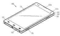
도 3a는 본 발명과 관련된 이동 단말기(100)의 일 예를 전면에서 바라본 사시도이다.3A is a front perspective view of an example of a
개시된 이동 단말기(100)는 바 형태의 단말기 바디를 구비하고 있다. 다만, 본 발명은 여기에 한정되지 않고, 와치 타입, 클립 타입, 안경 타입 또는 2 이상의 바디들이 상대 이동 가능하게 결합되는 폴더 타입, 플립 타입, 슬라이드 타입, 스윙 타입, 스위블 타입 등 다양한 구조에 적용될 수 있다.The disclosed
바디는 외관을 이루는 케이스(프레임, 하우징, 커버 등)를 포함한다. 본 실시예에서, 케이스는 프론트 케이스(101)와 리어 케이스(102)로 구분될 수 있다. 프론트 케이스(101)와 리어 케이스(102)의 사이에 형성된 공간에는 각종 전자부품들이 내장된다. 프론트 케이스(101)와 리어 케이스(102) 사이에는 적어도 하나의 중간 케이스가 추가로 배치될 수 있으며, 배터리(191)를 덮는 배터리 커버(103)가 리어 케이스(102)에 착탈 가능하게 구성될 수도 있다.The body includes a case (frame, housing, cover, etc.) that forms an exterior. In this embodiment, the case may be divided into a
케이스들은 합성수지를 사출하여 형성되거나 금속, 예를 들어 스테인레스 스틸(STS), 알루미늄(Al), 티타늄(Ti) 등으로 형성될 수도 있다.The cases may be formed by injecting synthetic resin, or may be formed of metal, for example, stainless steel (STS), aluminum (Al), titanium (Ti), or the like.
단말기 바디의 전면에는 디스플레이부(151), 제1음향출력모듈(153a), 제1카메라(121a), 제1조작유닛(131) 등이 배치되며, 측면에는 마이크(122), 인터페이스부(170), 제2조작유닛(132) 등이 구비될 수 있다.The
디스플레이부(151)는 이동 단말기(100)에서 처리되는 정보를 표시(출력)하도록 이루어진다. 디스플레이부(151)는 정보를 시각적으로 표현하는 액정 디스플레이(liquid crystal display, LCD), 박막 트랜지스터 액정 디스플레이(thin film transistor-liquid crystal display, TFT LCD), 유기 발광 다이오드(organic light-emitting diode, OLED), 플렉시블 디스플레이(flexible display), 3차원 디스플레이(3D display), 전자잉크 디스플레이(e-ink display) 중에서 적어도 하나를 포함할 수 있다.The
상기 디스플레이부(151)는 터치 방식에 의하여 제어 명령을 입력 받을 수 있게 터치감지수단을 포함할 수 있다. 디스플레이부(151) 상의 어느 한 곳에 대하여 터치가 이루어지면 터치감지수단은 이를 감지하고 그 터치된 위치에 대응하는 내용이 입력되게 구성될 수 있다. 터치 방식에 의하여 입력되는 내용은 문자 또는 숫자이거나, 각종 모드에서의 지시 또는 지정 가능한 메뉴항목 등일 수 있다.The
터치감지수단은 디스플레이부(151)에서 출력되는 시각 정보가 보일 수 있도록 투광성으로 형성되며, 밝은 곳에서 터치스크린의 시인성(visibility)을 높이기 위한 구조가 포함될 수 있다. 도 3a에 의하면, 디스플레이부(151)는 프론트 케이스(101)의 전면(front surface)의 대부분을 차지한다.The touch sensing means is formed to be translucent so that the visual information output from the
디스플레이부(151)의 양단부 중 일 단부에 인접한 영역에는 제1음향출력모듈(153a)과 제1카메라(121a)가 배치되고, 다른 단부에 인접한 영역에는 제1조작유닛(131)과 마이크(122)가 배치된다. 제2조작유닛(132, 도 3b 참조), 인터페이스부(170) 등은 단말기 바디의 측면에 배치될 수 있다.The first
제1음향출력모듈(153a)은 통화음을 사용자의 귀에 전달시키는 리시버(receiver) 또는 각종 알람음이나 멀티미디어의 재생음을 출력하는 라우드 스피커(loud speaker)의 형태로 구현될 수 있다.The first
제1음향출력모듈(153a)로부터 발생되는 사운드는 구조물 간의 조립틈을 따라 방출되도록 구성될 수 있다. 이 경우, 외관상 음향 출력을 위하여 독립적으로 형성되는 홀이 보이지 않거나, 숨겨져 이동 단말기(100)의 외관이 보다 심플해질 수 있다. 다만, 본 발명은 이에 한정되는 것은 아니며, 상기 사운드의 방출을 위한 홀이 윈도우에 형성될 수 있다.Sound generated from the first
제1카메라(121a)는 화상통화 모드 또는 촬영 모드에서 이미지 센서에 의해 얻어지는 정지영상 또는 동영상 등의 화상 프레임을 처리한다. 처리된 화상 프레임은 디스플레이부(151)에 표시될 수 있다.The
사용자 입력부(130)는 이동 단말기(100)의 동작을 제어하기 위한 명령을 입력 받기 위해 조작되는 것으로서, 제1 및 제2조작유닛(131, 132)을 포함할 수 있다. 제1 및 제2조작유닛(131, 132)은 조작부(manipulating portion)로도 통칭될 수 있으며, 터치, 푸쉬, 스크롤 등 사용자가 촉각적인 느낌을 가면서 조작하게 되는 방식(tactile manner)이라면 어떤 방식이든 채용될 수 있다.The
본 도면에서는 제1 조작유닛(131)이 터치키(touch key)인 것을 기준으로 예시하나, 본 발명은 이에 한정되는 것은 아니다. 예를 들어 제1 조작유닛(131)은 푸시키(mechanical key)가 되거나, 터치키와 푸시키의 조합으로 구성될 수 있다.In the drawing, the
제1 및/또는 제2조작유닛들(131, 132)에 의하여 입력되는 내용은 다양하게 설정될 수 있다. 예를 들어, 제1조작유닛(131)은 메뉴, 홈키, 취소, 검색 등과 같은 명령을 입력 받고, 제2조작유닛(132)은 제1음향출력모듈(153a)에서 출력되는 음향의 크기 조절 또는 디스플레이부(151)의 터치 인식 모드로의 전환 등과 같은 명령을 입력 받을 수 있다.Content input by the first and / or
마이크(122)는 사용자의 음성, 기타 소리 등을 입력 받도록 형성된다. 마이크(122)는 복수의 개소에 구비되어 스테레오 음향을 입력 받도록 구성될 수 있다.The
인터페이스부(170)는 이동 단말기(100)가 외부기기와 데이터 교환 등을 할 수 있게 하는 통로가 된다. 예를 들어, 인터페이스부(170)는 유선 또는 무선으로 이어폰과 연결하기 위한 접속단자, 근거리 통신을 위한 포트{예를 들어 적외선 포트(IrDA Port), 블루투스 포트(Bluetooth Port), 무선 랜 포트(Wireless LAN Port) 등}, 또는 이동 단말기(100)에 전원을 공급하기 위한 전원공급 단자들 중 적어도 하나일 수 있다. 이러한 인터페이스부(170)는 SIM(Subscriber Identification Module) 또는 UIM(User Identity Module), 정보 저장을 위한 메모리 카드 등의 외장형 카드를 수용하는 소켓의 형태로 구현될 수 있다.The
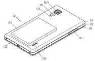
도 3b는 도 3a에 도시된 이동 단말기(100)의 후면 사시도이다.3B is a rear perspective view of the
도 3b를 참조하면, 단말기 바디의 후면, 다시 말해서 리어 케이스(102)에는 제2카메라(121b)가 추가로 장착될 수 있다. 제2카메라(121b)는 제1카메라(121a, 도 3a 참조)와 실질적으로 반대되는 촬영 방향을 가지며, 제1카메라(121a)와 서로 다른 화소를 가지는 카메라일 수 있다.Referring to FIG. 3B, a
예를 들어, 제1카메라(121a)는 화상 통화 등의 경우에 사용자의 얼굴을 촬영하여 상대방에 전송함에 무리가 없도록 저 화소를 가지며, 제2카메라(121b)는 일반적인 피사체를 촬영하고 바로 전송하지는 않는 경우가 많기에 고 화소를 가지는 것이 바람직하다. 제1 및 제2카메라(121a, 121b)는 회전 또는 팝업(pop-up) 가능하게 단말기 바디에 설치될 수도 있다.For example, the
제2카메라(121b)에 인접하게는 플래시(123)와 거울(124)이 추가로 배치된다. 플래시(123)는 제2카메라(121b)로 피사체를 촬영하는 경우에 피사체를 향해 빛을 비추게 된다. 거울(124)은 사용자가 제2카메라(121b)를 이용하여 자신을 촬영(셀프 촬영)하고자 하는 경우에, 사용자 자신의 얼굴 등을 비춰볼 수 있게 한다.The
단말기 바디의 후면에는 제2음향출력모듈(153b)이 추가로 배치될 수도 있다. 제2음향출력모듈(153b)은 제1음향출력모듈(153a, 도 3a 참조)과 함께 스테레오 기능을 구현할 수 있으며, 통화시 스피커폰 모드의 구현을 위하여 사용될 수도 있다.The second
단말기 바디의 측면에는 통화 등을 위한 안테나 외에 방송신호 수신용 안테나(미도시)가 추가적으로 배치될 수 있다. 방송수신모듈(111, 도 1 참조)의 일부를 이루는 안테나는 단말기 바디에서 인출 가능하게 설치될 수 있다.An antenna (not shown) for receiving a broadcast signal may be additionally disposed on the side of the terminal body. An antenna that forms part of the broadcast receiving module 111 (refer to FIG. 1) may be installed to be pulled out of the terminal body.
단말기 바디에는 이동 단말기(100)에 전원을 공급하기 위한 전원공급부(190, 도 1 참조)가 구비된다. 전원공급부(190)는 단말기 바디에 내장되거나, 단말기 바디의 외부에서 착탈 가능하게 구성되는 배터리(191)를 포함할 수 있다. 본 도면에서는 배터리 커버(103)가 배터리(191)를 덮도록 리어 케이스(102)에 결합되어 배터리(191)의 이탈을 제한하고, 배터리(191)를 외부 충격과 이물질로부터 보호하는 것을 예시하고 있다.The terminal body is provided with a power supply unit 190 (see FIG. 1) for supplying power to the
한편 이러한 개량에 힘입어, 이동 단말기는 설정한 목적지로의 길 안내를 제공하는 네비게이션(navigation) 기능을 제공할 수 있게 되었다. 그러나 실시간으로 도보 길 안내를 제공하는데는 어려움이 있다. 또한, 사용자가 길 안내를 받기 위해서는 항상 길 안내 제공 화면을 주시해야 하는 문제점이 있다.On the other hand, thanks to this improvement, the mobile terminal can provide a navigation function that provides a route guidance to a set destination. However, there is a difficulty in providing walking directions in real time. In addition, there is a problem that the user must always watch the road guidance providing screen to receive the road guidance.
이에 따라, 네비게이션 기능을 제공하는데 있어서 사용자의 편의를 향상시킬 수 있는 이동 단말기(100) 및 그것의 제어 방법에 대해 첨부된 도면을 참조하여 설명한다.Accordingly, with reference to the accompanying drawings, a
도 4는 본 발명에 따른 이동 단말기(100, 도 1 참조)의 일 실시 예를 설명하기 위한 순서도이다.4 is a flowchart illustrating an embodiment of a mobile terminal 100 (refer to FIG. 1) according to the present invention.
네비게이션 기능을 제공하는 본 발명에 따른 이동 단말기(100)는 입력부(130), 수신부(115), 제어부(180), 디스플레이부(151) 및 통신부(110)를 포함한다.The
도 4를 참조하면, 우선, 입력부(130)를 통해 외부로부터 목적지를 입력받는 단계(S410)가 진행된다.Referring to FIG. 4, first, a step (S410) of receiving a destination from the outside through the
실시 예로, 사용자는 길 안내를 받고자 하는 목적지를 물리적인 키 패드나 터치 패드를 통해 입력할 수 있다. 또 다른 실시 예로, 사용자는 마이크(122)를 통해 음성신호로 목적지를 입력할 수 있다.In an embodiment, the user may input a destination to receive the directions through a physical keypad or a touch pad. In another embodiment, the user may input a destination using a voice signal through the
그 다음, 이동 단말기(100)의 현재 위치를 산출하기 위한 신호를 수신부(115)를 통해 수신하는 단계(S420)가 진행된다.Next, a step (S420) of receiving a signal for calculating a current position of the
앞서 도 2a에서 설명한 바와 같이, 수신부(115)는 GPS 위성(300)으로부터 이동 단말기(100)의 현재 위치를 산출하기 위한 GPS 신호를 수신할 수 있다.As described above with reference to FIG. 2A, the
이어서, 이동 단말기(100)의 현재 위치를 산출하고, 산출한 이동 단말기(100)의 현재 위치에 따라 목적지에 도달하기 위한 진행 방향을 실시간으로 산출하는 단계(S430)가 진행된다.Subsequently, the step S430 of calculating a current position of the
그 후, 산출한 진행 방향을 나타내는 화살표를 디스플레이부(151)에 출력하는 단계(S440)가 진행된다. 이와 관련된 구체적인 사항은 후술한다.Thereafter, a step (S440) of outputting an arrow indicating the calculated moving direction to the
그리고 이동 단말기(100)의 현재 위치가 목적지와 일치하는지 여부, 즉 목적지에 도착하였는지를 판단(S450)하여 목적지에 도착한 경우 길 안내를 종료하게 된다.In addition, it is determined whether the current location of the
목적지에 도착하기 전, 사전에 설정한 차량 네비게이션 장치와 통신이 가능한지 판단하는 단계(S460)가 진행된다.Before reaching the destination, a step (S460) of determining whether communication with a preset vehicle navigation device is possible is performed.
그 결과 통신 가능한 차량 네비게이션 장치가 검색되지 않으면, 다시 GPS 신호를 수신하는 단계(S420)로 되돌아가게 된다.As a result, if the vehicle navigation apparatus that can communicate is not found, the process returns to step S420 of receiving a GPS signal again.
이와 달리 통신 가능한 차량 네비게이션 장치가 검색되면, 목적지와 이동 단말기(100)의 현재 위치를 차량 네비게이션 장치로 전송하는 단계(S470)가 진행된다.On the contrary, if a vehicle navigation apparatus that can communicate with the vehicle is searched, a step (S470) of transmitting a destination and a current location of the
이 단계(S470)에서는, 차량 네비게이션 장치와 사전에 설정한 프로토콜을 이용하여 데이터를 송수신할 수 있다. 이를 전송받은 차량 네비게이션 장치는 이동 단말기(100)의 현재 위치를 출발지로 하여 목적지로의 길 안내를 진행하게 된다. 즉, 이동 단말기(100)에서 진행되던 길 안내를 차량 네비게이션 장치가 이어서 진행하게 된다.In this step S470, data can be transmitted / received using the protocol set in advance with the vehicle navigation apparatus. The vehicle navigation device that receives the transmission guides the road to the destination using the current location of the
한편, 도 4는 길 안내 과정을 도식적으로 설명하기 위한 순서도로 본 발명에 따른 이동 단말기의 제어 방법이 상기 순서에 반드시 구속되는 것은 아니다.On the other hand, Figure 4 is a flow chart for explaining the road guidance process control method of the mobile terminal according to the present invention is not necessarily limited to the order.
구체적으로, GPS 신호를 수신하는 단계(S420)와 이동 단말기(100)의 현재 위치 및 진행 방향을 산출하는 단계(S430)는 실시간으로 연속하여 진행되거나 사전에 설정한 주기마다 진행될 수 있다.In detail, the receiving of the GPS signal (S420) and the calculating of the current position and the moving direction of the mobile terminal 100 (S430) may be performed in real time in succession or at predetermined intervals.
한편, 본 발명에 따른 이동 단말기(100)는 착용 가능한 장치(wearable device)로 구현될 수 있다. 예를 들면, 이동 단말기(100)는 착용 가능한 팔찌나 목걸이 형태로 구현될 수 있다.Meanwhile, the
도 5는 본 발명에 따른 이동 단말기(100)를 구현한 실시 예를 보여주는 개념도이다.5 is a conceptual diagram illustrating an embodiment of implementing a
도 5의 (a)를 참조하면, 이동 단말기(100)는 손목시계(wearable watch) 형태로 구현될 수 있다.Referring to FIG. 5A, the
예를 들면, 사용자는 이동 단말기(100)를 손목에 착용하여 휴대할 수 있다. 또한 평소에는(네비게이션 모드로 전환되기 전) 이동 단말기(100)를 통해 시간을 확인하거나 전화 및 메시지를 송수신할 수 있다.For example, a user may wear and carry the
이때, 사용자는 이동 단말기(100)를 네비게이션 모드로 전환시킬 수 있다.In this case, the user may switch the
구체적인 실시 예로, 디스플레이부(151)에 플리킹 입력을 가해 화면 잠금을 해제한 후, 특정 버튼을 터치하여 네비게이션 모드로 전환시킬 수 있다. 또는 목적지를 음성신호로 입력하여 네비게이션 모드로 전환시킬 수 있다.In a specific embodiment, the screen lock may be applied to the
도 5의 (b)를 참조하면, 이동 단말기(100)가 네비게이션 모드로 전환되었음을 확인할 수 있다.Referring to FIG. 5B, it may be confirmed that the
구체적으로, 현재 이동 단말기(100)의 위치를 기준으로 목적지에 도달하기 위한 진행 방향을 나타내는 화살표가 출력될 수 있다. 도 5의 (b)에서는, 현재 위치에서 좌우의 이동 가능 경로 중 오른쪽으로 이동해야 함을 확인할 수 있다.In detail, an arrow indicating a moving direction for reaching the destination may be output based on the location of the current
또한, 길 안내를 시작하는 시점에서의 이동 단말기(100)의 위치로부터 목적지까지의 거리 및 소요시간, 현재 이동 단말기(100)의 위치로부터 목적지까지 도달하는데 걸리는 소요시간 등의 추가적인 정보가 함께 출력될 수 있다.In addition, additional information such as a distance and a required time from the position of the
도 5의 (b)에서는, 출발지로부터 목적지까지의 거리는 3km이고 도보로 20분이 걸리며 현재 위치에서는 3분 후에 목적지에 도착할 수 있음을 확인할 수 있다.In Figure 5 (b), it can be seen that the distance from the starting point to the destination is 3km and takes 20 minutes on foot and can reach the destination after 3 minutes from the current location.
한편, 앞서 설명한 바와 같이 이동 단말기(100)는 진행 방향을 나타내는 화살표를 출력하는 TBT(Turn By Turn) 방식으로 길 안내를 수행할 수 있다.Meanwhile, as described above, the
도 6은 진행 방향을 나타내는 화살표의 실시 예를 보여주는 개념도이다.6 is a conceptual diagram illustrating an embodiment of an arrow indicating a moving direction.
도 6의 (a)는 직진 방향을 나타내는 화살표의 실시 예를 보여주는 개념도이다.6A is a conceptual diagram illustrating an embodiment of an arrow indicating a straight direction.
도 6의 (a)를 참조하면, 직진해야 하는 거리 정도에 따라 화살표의 길이를 다르게 출력할 수 있다. 예를 들면, 상대적으로 먼 거리를 나타내는 화살표를 더 길게 출력할 수 있다.Referring to FIG. 6A, the length of the arrow may be differently output according to the distance to be straight. For example, an arrow indicating a relatively long distance may be output longer.
도 6의 (b) 및 (c)는 각각 우회전 및 좌회전을 나타내는 화살표의 실시 예를 보여주는 개념도이다.(B) and (c) of FIG. 6 are conceptual views illustrating an embodiment of an arrow indicating a right turn and a left turn, respectively.
도 6의 (b) 및 (c)를 참조하면, 우회전 및 좌회전의 정도에 따라 화살표가 구부러지는 각도를 상대적으로 다르게 출력할 수 있다.Referring to (b) and (c) of FIG. 6, the angle at which the arrow is bent may be relatively different depending on the degree of right turn and left turn.
도 6의 (d)를 참조하면, 복수의 이동 가능 경로 및 진행 방향을 나타내는 화살표를 출력할 수 있다.Referring to FIG. 6D, arrows indicating a plurality of movable paths and a moving direction may be output.
구체적으로, 610의 경우 좌우의 이동 가능 경로 중 오른쪽 방향의 화살표를 통해 우회전해야 함을 확인할 수 있다. 마찬가지로, 620의 경우 분기점에서 직진해야하며 630의 경우 분기점에서 좌회전해야 함을 확인할 수 있다.In detail, in the case of 610, it may be confirmed that the right side of the left and right movable paths should be turned through the arrow in the right direction. Similarly, in case of 620, it is necessary to go straight at the fork, and in case of 630, turn left at the fork.
이와 같은 출력 방식으로, 사용자는 진행 방향이나 목적지까지의 거리 정도를 직관적으로 파악할 수 있게 된다.With this output method, the user can intuitively grasp the direction of travel and the distance to the destination.
또한, 사전에 설정한 신호를 출력하여 사용자에게 진행 방향을 알려줄 수 있다. 구체적으로, 신호는 음성신호, 진동신호 및 기타 음향신호를 포함할 수 있으며, 신호출력 방식은 사용자에 의해 설정될 수 있다. 또한 신호는 상기 화살표와 함께 출력될 수도 있다.In addition, by outputting a signal set in advance to inform the user of the direction of progress. In detail, the signal may include a voice signal, a vibration signal, and other sound signals, and the signal output method may be set by a user. The signal may also be output with the arrow.
실시 예로, 직진해야 하는 경우 Beep음을 일정 시간 출력하거나 일정 시간 동안 지속하는 진동을 출력할 수 있다. 또는 "직진"의 음성신호를 출력할 수도 있다. 각각의 출력 방식은 전부 또는 일부 선택되어 동시에 또는 순차적으로 출력될 수 있으며, 도 6의 (a)에서의 화살표와 함께 출력될 수도 있다.For example, when it is necessary to go straight, the Beep sound may be output for a predetermined time or the vibration may be output for a predetermined time. Alternatively, a voice signal of "going straight" may be output. Each output method may be selected in whole or in part and may be output simultaneously or sequentially, or may be output with an arrow in FIG.
또 다른 실시 예로, 우회전해야 하는 경우 Beep음이나 진동을 두 번 출력할 수 있다. 또는 "우회전"의 음성신호를 출력할 수도 있다. 각각의 출력 방식은 전부 또는 일부 선택되어 동시에 또는 순차적으로 출력될 수 있으며, 도 6의 (b)에서의 화살표와 함께 출력될 수도 있다.In another embodiment, when it is necessary to turn right, it may output two beeps or vibrations. Alternatively, a voice signal of "right turn" may be output. Each output scheme may be selected in whole or in part and may be output simultaneously or sequentially, or may be output with an arrow in FIG.
또 다른 실시 예로, 좌회전해야 하는 경우 Beep음이나 진동을 한 번 출력할 수 있다. 또는 "좌회전"의 음성신호를 출력할 수도 있다. 각각의 출력 방식은 전부 또는 일부 선택되어 동시에 또는 순차적으로 출력될 수 있으며, 도 6의 (c)에서의 화살표와 함께 출력될 수도 있다.In another embodiment, when it is necessary to turn left, a beep sound or vibration may be output once. Alternatively, a voice signal of "left turn" may be output. Each output scheme may be selected in whole or in part and may be output simultaneously or sequentially, or may be output with an arrow in FIG.
또한, 신호나 화살표가 출력되는 시점을 다양한 방식으로 설정할 수 있다.In addition, the time point at which the signal or the arrow is output can be set in various ways.
구체적으로, 이동 단말기(100)의 현재 위치에 따라 목적지에 도달하기 위한 진행 방향이 변하는 경우, 변화된 진행 방향을 나타내는 신호나 화살표를 출력할 수 있다.Specifically, when the traveling direction for reaching the destination is changed according to the current position of the
예를 들면, 목적지로의 이동 중 교차로를 지나게 되는 경우, 분기점에 도달하기 10m 전에 앞서 설명한 신호나 화살표를 출력할 수 있다. 또는, 사전에 설정한 주기나 사용자의 요청이 있는 경우 이를 출력할 수도 있다.For example, when passing through an intersection while moving to a destination, the aforementioned signal or arrow may be output 10m before reaching the branch point. Or, if a preset cycle or a user's request is requested, this can be output.
또 다른 실시 예로, 저속에서의 GPS 오차를 고려하여 경로에서 일정 거리 이상 벗어난 경우 현재 위치에서 경로로 되돌아오는 가장 가까운 방향을 출력할 수 있다. 이를 위해, GPS 오차가 있어도 오류없이 도로 위에 matching시키는 기술이 이용될 수 있다.As another embodiment, when the deviation from the path by more than a predetermined distance in consideration of the GPS error at low speed may output the closest direction to return to the path from the current position. To this end, a technique of matching on a road without error even if there is a GPS error may be used.
도 7은 목적지 설정과 관련된 사용자 인터페이스의 실시 예를 보여주는 개념도이다.7 is a conceptual diagram illustrating an embodiment of a user interface related to destination setting.
도 7의 (a)를 참조하면, 사용자는 목적지나 경유지를 음성으로 입력할 수 있다. 예를 들면, 사용자가 음성으로 "이마트"를 목적지로 입력할 수 있다.Referring to FIG. 7A, a user may input a destination or a waypoint by voice. For example, a user may voice input "E-Mart" as a destination.
도 7의 (b)를 참조하면, 도 7의 (a)에서 입력된 음성을 인식하여 이마트까지의 거리, 소요시간 등의 정보(710)와 지도(720)를 출력할 수 있다. 그리고 사용자는 목적지 설정(730)을 터치하여 출력된 지도(720) 상의 이마트를 목적지로 설정할 수 있다.Referring to FIG. 7B, the voice input in FIG. 7A may be recognized to
실시 예로, 사용자는 "최근 목적지"를 입력하여 목적지 리스트를 제공받고, 이중 목적지를 선택할 수 있다.In an embodiment, the user may be provided with a list of destinations by inputting "recent destinations" and select a dual destination.
도 7의 (c)를 참조하면, 도 7의 (a)에서 사용자가 "최근 목적지"를 음성으로 입력하면, 최근 검색된 목적지 리스트(740)가 출력될 수 있다.Referring to FIG. 7C, when a user inputs "recent destination" as a voice in FIG. 7A, a recently searched destination list 740 may be output.
이에 따라, 목적지를 선택한 후 위치보기(750)를 터치하여 선택한 목적지의 위치를 확인할 수 있다. 또는, 바로탐색(760)을 터치하여 선택한 목적지로의 길 안내를 시작할 수 있다.Accordingly, after selecting a destination, the
또 다른 실시 예로, 사용자는 최근 검색지, 이전 출발지, 즐겨찾는 곳 등을 음성으로 입력하여 목적지 리스트를 제공받을 수 있다.In another embodiment, the user may be provided with a list of destinations by voice inputting a recent search place, a previous departure place, a favorite place, and the like.
이때, 목적지나 경유지를 설정할 수 있는 API가 제공될 수 있다. 예를 들면, <slot> <목적지> 등으로 query를 보내고 결과를 확인할 수 있다. 또 다른 예로, <nearby> <편의점>은 근처 편의점을 찾는 요청으로 인식될 수 있다.In this case, an API for setting a destination or waypoint may be provided. For example, you can send a query to <slot> <destination> and check the results. As another example, <nearby> <convenience store> may be recognized as a request for finding a nearby convenience store.
또한, 경로 정보의 API가 제공될 수 있다. 이에 따라, 경로를 요청한 경우 XML 형태로 query/request할 수 있고 출발지로부터 목적지까지 각 경로 지점(way point)을 포함한 경로 정보가 제공될 수 있다. 이를 위해 네비게이션 지도 개발 업체로부터 관련 정보를 수신할 수 있다.In addition, an API of route information may be provided. Accordingly, when requesting a route, the request may be queried / requested in the form of XML, and route information including each way point from a source to a destination may be provided. To this end, relevant information may be received from a navigation map developer.
한편, 설정된 목적지로의 길 안내 중 앞서 설명한 것과 같은 방식으로 목적지를 변경할 수 있다. 이는 특히, 차량 네비게이션 장치에 의해 길 안내 진행 중 유용하게 쓰일 수 있다. 이와 관련된 구체적인 사항은 후술한다.Meanwhile, the destination may be changed in the same manner as described above among the road guidance to the set destination. This may be particularly useful during the road guidance process by the vehicle navigation apparatus. Specific matters related to this will be described later.
도 8은 길 안내 방식과 관련된 사용자 인터페이스의 실시 예를 보여주는 개념도이다.8 is a conceptual diagram illustrating an embodiment of a user interface associated with a road guidance method.
도 8의 (a)를 참조하면, 앞서 설명한 바와 같이, 목적지까지의 길 안내는 화살표를 이용한 TBT 방식으로 이루어질 수 있다. 이때, 사용자는 현재 위치와 목적지를 나타내는 지도를 표시하는 화면으로 전환시킬 수 있다.Referring to FIG. 8A, as described above, the road guidance to the destination may be performed by using a TBT method using an arrow. In this case, the user may switch to a screen displaying a map indicating a current location and a destination.
도 8의 (b)를 참조하면, 도 8의 (a)에서 사용자가 MAP(810)을 터치하면 현재 위치와 목적지를 나타내는 지도(820)가 출력된다. 또한, TBT 전환(830)을 터치하여 도 8의 (a) 상태로 되돌아갈 수 있다.Referring to FIG. 8B, when the user touches the
실시 예로, 현재 위치와 목적지를 나타내는 지도(820)와 진행 방향을 나타내는 화살표가 함께 출력될 수도 있다.For example, a
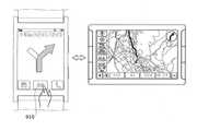
도 9는 차량 네비게이션과 연동되는 실시 예를 보여주는 개념도이다.9 is a conceptual diagram illustrating an embodiment linked to vehicle navigation.
도 9를 참조하면, 본 발명에 따른 이동 단말기(100)는 사전에 설정한 차량 네비게이션 장치와 연동될 수 있다. 이때, 사전에 설정한 프로토콜을 이용하여 데이터를 송수신할 수 있다.Referring to FIG. 9, the
구체적으로, 이동 단말기(100)를 이용하여 길 안내를 받는 중 사전에 설정한 차량 네비게이션 장치가 인식되면, 이동 단말기(100)에서 진행되던 길 안내가 차량 네비게이션에서 이루어지게 된다. 이를 위해, 차량 네비게이션 장치는 이동 단말기(100)와 일정 거리 정도로 근접하여야 한다.In detail, when the vehicle navigation apparatus set in advance is recognized while receiving the road guidance using the
또한, 목적지에 도착하기 전 차량에서 하차하는 경우 차량 네비게이션 장치를 통해 이루어지던 길 안내가 이동 단말기(100)를 통해 이루어지게 된다.In addition, when getting off from the vehicle before arriving at the destination, the road guidance, which was made through the vehicle navigation device, is made through the
이를 위해, 이동 단말기(100) 및 차량 네비게이션 장치는 근접한 상호 장치를 인식할 수 있어야 한다. 또는, 전환 버튼(910)이나 전환 음성 인식 명령을 통해 전환될 수도 있다.To this end, the
앞서 설명한 바와 같이, 이동 단말기(100)와 차량 네비게이션은 사전에 설정한 프로토콜을 이용하여 데이터를 송수신할 수 있다.As described above, the
그 결과, 사용자는 차량 운정 중 목적지를 변경할 때 차량 네비게이션에 목적지를 새로 입력할 필요가 없게 된다. 이때 차량 마이크가 아닌 이동 단말기(100)의 마이크(122)를 이용하게 되므로, 음성 인식의 정확도가 증가하게 된다.As a result, the user does not have to enter a new destination in the vehicle navigation when changing the destination during vehicle operation. In this case, since the
본 발명에 따른 이동 단말기(100)를 이용할 수 있는 추가적인 실시 예로, 차량의 스마트 키로 이용하여 보안을 강화할 수 있다.As an additional embodiment in which the
또는, 이동 단말기(100) 착용자의 신체 정보를 이용할 수 있다.Alternatively, the body information of the wearer of the
예를 들면, 이동 단말기(100)는 착용자의 심장 박동수 등의 신체 상태를 파악할 수 있으며, 착용자의 신체 이상이 감지되면 긴급 전화를 걸거나 목적지를 병원으로 변경할 수 있다.For example, the
한편, 본 발명에 따른 이동 단말기(100)는 네트워크가 지원되는 조건으로 서술하였으나, 이동 단말기(100) 자체에 와이파이나 테터링 등의 서비스가 지원될 수 있다.Meanwhile, although the
그 결과, 스마트 폰이나 태블릿 등의 네트워크에 연결되어 사용될 수 있다. 또한, 길 안내나 음성 인식의 리소스를 스마트 폰이나 태블릿 등으로부터 사용하고 테터링을 통해 기 설정된 프로토콜로 관련 정보를 가져올 수 있다. 이에 따라, 3G나 LTE와 같은 네트워크 모뎀이 없어도 관련 기능을 구현할 수 있다.As a result, it can be used by being connected to a network such as a smartphone or a tablet. In addition, it is possible to use the resources of the direction guidance or voice recognition from a smart phone or tablet, and bring related information to a preset protocol through tethering. Accordingly, related functions can be implemented without a network modem such as 3G or LTE.
이와 같이, 네트워크 모뎀이 없는 단말기(100)는 단가가 저렴해질 수 있다. 또한, 기존 모바일 폰을 이용하여 테터링을 통해 실시간 길 안내를 받을 수 있다.As such, the terminal 100 without the network modem may be inexpensive. In addition, you can receive real-time directions through tethering using an existing mobile phone.
또한, 본 명세서에 개시된 일 실시 예에 의하면, 전술한 방법은, 프로그램이 기록된 매체에 프로세서가 읽을 수 있는 코드로서 구현하는 것이 가능하다. 프로세서가 읽을 수 있는 매체의 예로는, ROM, RAM, CD-ROM, 자기 테이프, 플로피 디스크, 광 데이터 저장장치 등이 있으며, 캐리어 웨이브(예를 들어, 인터넷을 통한 전송)의 형태로 구현되는 것도 포함한다.In addition, according to one embodiment disclosed herein, the above-described method may be implemented as code that can be read by a processor in a medium in which a program is recorded. Examples of processor-readable media include ROM, RAM, CD-ROM, magnetic tape, floppy disk, optical data storage, and the like, and may be implemented in the form of a carrier wave (for example, transmission over the Internet). Include.
상기와 같이 설명된 이동 단말기는 상기 설명된 실시 예들의 구성과 방법이 한정되게 적용될 수 있는 것이 아니라, 상기 실시 예들은 다양한 변형이 이루어질 수 있도록 각 실시 예들의 전부 또는 일부가 선택적으로 조합되어 구성될 수도 있다.The above-described mobile terminal is not limited to the configuration and method of the above-described embodiments, but the embodiments may be configured by selectively combining all or some of the embodiments so that various modifications can be made. It may be.
Claims (10)
Translated fromKorean목적지를 입력받는 입력부;
상기 이동 단말기의 현재 위치를 산출하기 위한 신호를 수신하는 수신부;
상기 이동 단말기의 현재 위치에 따라 상기 목적지에 도달하기 위한 진행 방향을 실시간으로 산출하는 제어부;
상기 산출한 진행 방향을 나타내는 화살표를 출력하는 디스플레이부; 및
상기 목적지와 상기 이동 단말기의 현재 위치를 사전에 설정한 차량 네비게이션 장치로 전송하는 통신부;를 포함하며,
상기 차량 네비게이션 장치는 상기 이동 단말기의 현재 위치를 출발지로 하여 상기 목적지로 길 안내 하며,
상기 제어부는,
상기 이동 단말기의 사용자가 상기 목적지에 도착하기 전에 차량에서 하차하는지를 판단하고, 상기 목적지에 도착하기 전에 하차한 경우, 상기 차량 네비게이션 장치에서 이루어지던 길 안내가 다시 상기 이동 단말기에서 이루어지도록 상기 디스플레이부를 제어하는 것을 특징으로 하는 이동 단말기.In a mobile terminal providing a navigation function,
An input unit for receiving a destination;
A receiver which receives a signal for calculating a current position of the mobile terminal;
A controller configured to calculate a moving direction for reaching the destination in real time according to a current position of the mobile terminal;
A display unit which outputs an arrow indicating the calculated moving direction; And
And a communication unit configured to transmit the destination and the current location of the mobile terminal to a preset vehicle navigation device.
The vehicle navigation device guides the way to the destination based on the current location of the mobile terminal,
The control unit,
It is determined whether the user of the mobile terminal gets off from the vehicle before arriving at the destination, and if the user gets off before arriving at the destination, the display unit is controlled so that the road guidance made by the vehicle navigation device is again performed at the mobile terminal. Mobile terminal, characterized in that.
상기 입력부는,
상기 목적지를 음성신호로 입력받는 것을 특징으로 하는 이동 단말기.The method of claim 1,
The input unit,
Mobile terminal, characterized in that receiving the destination as a voice signal.
상기 제어부는,
상기 이동 단말기의 현재 위치에 따라 상기 목적지에 도달하기 위한 진행 방향이 변하는 경우, 상기 변화된 진행 방향을 나타내는 화살표가 출력되도록 상기 디스플레이부를 제어하는 것을 특징으로 하는 이동 단말기.The method of claim 1,
The control unit,
And controlling the display unit to output an arrow indicating the changed direction of travel when the direction of travel for reaching the destination is changed according to the current location of the mobile terminal.
상기 제어부는,
상기 산출한 진행 방향을 나타내는 사전에 설정한 신호가 출력되도록 제어하는 것을 특징으로 하는 이동 단말기.The method of claim 1,
The control unit,
And a predetermined signal indicating the calculated travel direction is output.
상기 통신부는,
상기 차량 네비게이션 장치와 사전에 설정한 프로토콜을 이용하여 데이터를 송수신하는 것을 특징으로 하는 이동 단말기.The method of claim 1,
The communication unit,
And transmitting and receiving data using the protocol set in advance with the vehicle navigation apparatus.
(a) 목적지를 입력받는 단계;
(b) 상기 이동 단말기의 현재 위치를 산출하기 위한 신호를 수신하는 단계;
(c) 상기 이동 단말기의 현재 위치를 산출하고, 상기 산출한 이동 단말기의 현재 위치에 따라 상기 목적지에 도달하기 위한 진행 방향을 실시간으로 산출하는 단계;
(d) 상기 산출한 진행 방향을 나타내는 화살표를 디스플레이부에 출력하는 단계; 및
(e) 상기 목적지와 상기 이동 단말기의 현재 위치를 사전에 설정한 차량 네비게이션 장치로 전송하는 단계;를 포함하며,
상기 차량 네비게이션 장치는 상기 이동 단말기의 현재 위치를 출발지로 하여 상기 목적지로 길 안내 하며,
상기 이동 단말기의 사용자가 상기 목적지에 도착하기 전에 차량에서 하차하는지를 판단하는 단계; 및
상기 목적지에 도착하기 전에 하차한 경우, 상기 차량 네비게이션 장치에서 이루어지던 길 안내가 다시 상기 이동 단말기에서 이루어지도록 상기 디스플레이부를 제어하는 단계를 포함하는 것을 특징으로 하는 이동 단말기의 제어 방법.In the control method of a mobile terminal providing a navigation function,
(a) receiving a destination;
(b) receiving a signal for calculating a current position of the mobile terminal;
(c) calculating a current position of the mobile terminal and calculating in real time a direction for reaching the destination according to the calculated current position of the mobile terminal;
(d) outputting an arrow indicating the calculated traveling direction on a display unit; And
(e) transmitting the destination and the current location of the mobile terminal to a preset vehicle navigation device;
The vehicle navigation device guides the way to the destination based on the current location of the mobile terminal,
Determining whether the user of the mobile terminal gets off the vehicle before arriving at the destination; And
And controlling the display unit so that the road guide performed by the vehicle navigation apparatus is again performed by the mobile terminal when the bus is departed before arriving at the destination.
상기 (a) 단계는,
상기 목적지를 음성신호로 입력받는 단계를 포함하는 것을 특징으로 하는 이동 단말기의 제어 방법.The method of claim 6,
In step (a),
And receiving the destination as a voice signal.
상기 (d) 단계는,
상기 이동 단말기의 현재 위치에 따라 상기 목적지에 도달하기 위한 진행 방향이 변하는 경우, 상기 변화된 진행 방향을 나타내는 화살표를 상기 디스플레이부에 출력하는 단계를 포함하는 것을 특징으로 하는 이동 단말기의 제어 방법.The method of claim 6,
In step (d),
And outputting an arrow indicating the changed moving direction to the display unit when the moving direction for reaching the destination is changed according to the current position of the mobile terminal.
상기 (d) 단계는,
상기 산출한 진행 방향을 나타내는 사전에 설정한 신호를 출력하는 단계를 포함하는 것을 특징으로 하는 이동 단말기의 제어 방법.The method of claim 6,
In step (d),
And outputting a pre-set signal representing the calculated traveling direction.
상기 (e) 단계는,
상기 차량 네비게이션 장치와 사전에 설정한 프로토콜을 이용하여 데이터를 송수신하는 단계를 포함하는 것을 특징으로 하는 이동 단말기의 제어 방법.The method of claim 6,
In step (e),
And transmitting / receiving data by using a protocol set in advance with the vehicle navigation apparatus.
Priority Applications (3)
| Application Number | Priority Date | Filing Date | Title |
|---|---|---|---|
| KR1020130042398AKR102011457B1 (en) | 2013-04-17 | 2013-04-17 | Mobile terminal and control method thereof |
| PCT/KR2014/003307WO2014171734A2 (en) | 2013-04-17 | 2014-04-16 | Mobile terminal and control method therefor |
| US14/784,689US9869556B2 (en) | 2013-04-17 | 2014-04-16 | Mobile terminal and control method therefor |
Applications Claiming Priority (1)
| Application Number | Priority Date | Filing Date | Title |
|---|---|---|---|
| KR1020130042398AKR102011457B1 (en) | 2013-04-17 | 2013-04-17 | Mobile terminal and control method thereof |
Publications (2)
| Publication Number | Publication Date |
|---|---|
| KR20140124634A KR20140124634A (en) | 2014-10-27 |
| KR102011457B1true KR102011457B1 (en) | 2019-08-19 |
Family
ID=51731937
Family Applications (1)
| Application Number | Title | Priority Date | Filing Date |
|---|---|---|---|
| KR1020130042398AActiveKR102011457B1 (en) | 2013-04-17 | 2013-04-17 | Mobile terminal and control method thereof |
Country Status (3)
| Country | Link |
|---|---|
| US (1) | US9869556B2 (en) |
| KR (1) | KR102011457B1 (en) |
| WO (1) | WO2014171734A2 (en) |
Families Citing this family (93)
| Publication number | Priority date | Publication date | Assignee | Title |
|---|---|---|---|---|
| JP5802830B2 (en) | 2011-06-05 | 2015-11-04 | アップル インコーポレイテッド | System and method for displaying notifications received from multiple applications |
| WO2014143776A2 (en) | 2013-03-15 | 2014-09-18 | Bodhi Technology Ventures Llc | Providing remote interactions with host device using a wireless device |
| GB2519325A (en)* | 2013-10-17 | 2015-04-22 | Ibm | Switching of electronic social presence between devices |
| KR102405189B1 (en) | 2013-10-30 | 2022-06-07 | 애플 인크. | Displaying relevant user interface objects |
| US10043185B2 (en) | 2014-05-29 | 2018-08-07 | Apple Inc. | User interface for payments |
| US20150350146A1 (en) | 2014-05-29 | 2015-12-03 | Apple Inc. | Coordination of message alert presentations across devices based on device modes |
| US9967401B2 (en) | 2014-05-30 | 2018-05-08 | Apple Inc. | User interface for phone call routing among devices |
| TWI647608B (en) | 2014-07-21 | 2019-01-11 | 美商蘋果公司 | Remote user interface |
| US10387962B1 (en) | 2014-07-21 | 2019-08-20 | State Farm Mutual Automobile Insurance Company | Methods of reconstructing an accident scene using telematics data |
| WO2016018040A1 (en)* | 2014-07-31 | 2016-02-04 | Samsung Electronics Co., Ltd. | A terminal and a method of controlling the same |
| US10339293B2 (en) | 2014-08-15 | 2019-07-02 | Apple Inc. | Authenticated device used to unlock another device |
| TWI600322B (en) | 2014-09-02 | 2017-09-21 | 蘋果公司 | Method for operating an electronic device with an integratd camera and related electronic device and non-transitory computer readable storage medium |
| WO2016036603A1 (en) | 2014-09-02 | 2016-03-10 | Apple Inc. | Reduced size configuration interface |
| WO2016036552A1 (en) | 2014-09-02 | 2016-03-10 | Apple Inc. | User interactions for a mapping application |
| US9746913B2 (en)* | 2014-10-31 | 2017-08-29 | The United States Of America As Represented By The Secretary Of The Navy | Secured mobile maintenance and operator system including wearable augmented reality interface, voice command interface, and visual recognition systems and related methods |
| KR102257474B1 (en)* | 2014-11-04 | 2021-05-31 | 삼성전자 주식회사 | Method for transmitting and receiving data and Electronic device using the same |
| KR101811691B1 (en)* | 2014-11-12 | 2017-12-22 | 주식회사 퓨처플레이 | Method, system and computer-readable recording medium for providing contents by at least one device out of a plurality of devices based on angular relationship among said plurality of devicescontext information |
| US9874456B2 (en)* | 2014-11-28 | 2018-01-23 | Here Global B.V. | Method, apparatus and computer program product for providing a destination preview |
| US20160162678A1 (en)* | 2014-12-08 | 2016-06-09 | Hyundai Motor Company | Vehicle and method of controlling vehicle |
| US9207092B1 (en)* | 2014-12-22 | 2015-12-08 | Google Inc. | Displaying navigation information within a secondary user interface of a mobile device |
| USD789417S1 (en) | 2014-12-22 | 2017-06-13 | Google Inc. | Portion of a display panel with a transitional graphical user interface component for a lock screen interface |
| KR101638095B1 (en)* | 2015-01-16 | 2016-07-20 | 한국과학기술원 | Method for providing user interface through head mount display by using gaze recognition and bio-signal, and device, and computer-readable recording media using the same |
| KR101711835B1 (en)* | 2015-01-30 | 2017-03-03 | 엘지전자 주식회사 | Vehicle, Vehicle operating method and wearable device operating method |
| US20160224973A1 (en) | 2015-02-01 | 2016-08-04 | Apple Inc. | User interface for payments |
| KR20160095409A (en)* | 2015-02-03 | 2016-08-11 | 엘지전자 주식회사 | Mobile terminal and method for controlling the same |
| US9574896B2 (en)* | 2015-02-13 | 2017-02-21 | Apple Inc. | Navigation user interface |
| DE102015102352A1 (en)* | 2015-02-19 | 2016-08-25 | Dr. Ing. H.C. F. Porsche Aktiengesellschaft | Method and device for monitoring a resting state in a motor vehicle |
| US10216351B2 (en) | 2015-03-08 | 2019-02-26 | Apple Inc. | Device configuration user interface |
| US10328855B2 (en) | 2015-03-18 | 2019-06-25 | Uber Technologies, Inc. | Methods and systems for providing alerts to a connected vehicle driver and/or a passenger via condition detection and wireless communications |
| US9610893B2 (en)* | 2015-03-18 | 2017-04-04 | Car1St Technologies, Llc | Methods and systems for providing alerts to a driver of a vehicle via condition detection and wireless communications |
| CN107409283A (en)* | 2015-04-09 | 2017-11-28 | 戴姆勒股份公司 | The seamless handover of continuously active between vehicle and wearable device |
| KR20180012751A (en) | 2015-05-28 | 2018-02-06 | 엘지전자 주식회사 | Wearable terminal that displays optimized screen according to the situation |
| KR102366473B1 (en)* | 2015-06-16 | 2022-02-23 | 엘지전자 주식회사 | Mobile terminal and method for controlling the same |
| US9940637B2 (en) | 2015-06-05 | 2018-04-10 | Apple Inc. | User interface for loyalty accounts and private label accounts |
| US20160358133A1 (en) | 2015-06-05 | 2016-12-08 | Apple Inc. | User interface for loyalty accounts and private label accounts for a wearable device |
| WO2016199967A1 (en)* | 2015-06-12 | 2016-12-15 | (주)블루와이즈 | User intention input system on basis of pattern and sensor |
| CN105116817A (en)* | 2015-06-26 | 2015-12-02 | 小米科技有限责任公司 | Balance car management method and device |
| US10351009B2 (en)* | 2015-07-31 | 2019-07-16 | Ford Global Technologies, Llc | Electric vehicle display systems |
| WO2017026111A1 (en)* | 2015-08-07 | 2017-02-16 | セイコーエプソン株式会社 | Information processing system, information processing device, terminal device, and information processing method |
| US10053001B1 (en)* | 2015-09-24 | 2018-08-21 | Apple Inc. | System and method for visual communication of an operational status |
| US10522141B2 (en)* | 2015-10-28 | 2019-12-31 | Ford Global Technologies, Llc | Vehicle voice recognition including a wearable device |
| DE102015221419A1 (en)* | 2015-11-02 | 2017-05-04 | Bayerische Motoren Werke Aktiengesellschaft | Method, system and vehicle comprising the system for transmitting a navigation target to a navigation device of the vehicle |
| US10137777B2 (en) | 2015-11-03 | 2018-11-27 | GM Global Technology Operations LLC | Systems and methods for vehicle system control based on physiological traits |
| KR102149295B1 (en)* | 2015-11-10 | 2020-08-28 | 현대자동차주식회사 | Vehicle control apparatus and method for operation on passing lane |
| US20170131775A1 (en)* | 2015-11-10 | 2017-05-11 | Castar, Inc. | System and method of haptic feedback by referral of sensation |
| US9944295B2 (en) | 2015-11-27 | 2018-04-17 | Bragi GmbH | Vehicle with wearable for identifying role of one or more users and adjustment of user settings |
| US10099636B2 (en) | 2015-11-27 | 2018-10-16 | Bragi GmbH | System and method for determining a user role and user settings associated with a vehicle |
| US10104460B2 (en) | 2015-11-27 | 2018-10-16 | Bragi GmbH | Vehicle with interaction between entertainment systems and wearable devices |
| US20170153636A1 (en)* | 2015-11-27 | 2017-06-01 | Bragi GmbH | Vehicle with wearable integration or communication |
| US10018732B2 (en) | 2015-12-21 | 2018-07-10 | Clarion Co., Ltd. | Information processing apparatus and information processing system |
| US11392117B2 (en) | 2016-02-18 | 2022-07-19 | Sony Corporation | Method and device for managing interaction between a wearable device and a vehicle |
| US20180329495A1 (en)* | 2016-02-24 | 2018-11-15 | Hewlett-Packard Development Company, L.P. | Notifications in a wearable device |
| CN107278367B (en)* | 2016-02-29 | 2020-02-21 | 华为技术有限公司 | A mobile terminal, wearable device and message transmission method |
| EP3217231A1 (en)* | 2016-03-10 | 2017-09-13 | Tissot S.A. | Navigation system with remote display |
| CN107478377B (en)* | 2016-06-08 | 2023-06-06 | 深圳市艾而特传感器精密有限公司 | Double-picture display digital barometer |
| CN114693289A (en) | 2016-06-11 | 2022-07-01 | 苹果公司 | User interface for trading |
| US10621581B2 (en) | 2016-06-11 | 2020-04-14 | Apple Inc. | User interface for transactions |
| AU2017100667A4 (en) | 2016-06-11 | 2017-07-06 | Apple Inc. | Activity and workout updates |
| JP6702001B2 (en)* | 2016-06-14 | 2020-05-27 | 株式会社デンソー | Imaging device and imaging system |
| US9916501B2 (en)* | 2016-07-22 | 2018-03-13 | Yung-Hui Li | Smart eyeglasses with iris recognition device |
| US10759424B2 (en)* | 2016-08-16 | 2020-09-01 | Honda Motor Co., Ltd. | Vehicle data selection system for modifying automated driving functionalities and method thereof |
| US9730255B1 (en)* | 2016-08-30 | 2017-08-08 | Polycom, Inc. | Room-specific pairing via a combined ultrasonic beacon/bluetooth approach |
| DE102016217532A1 (en) | 2016-09-14 | 2018-03-15 | Continental Teves Ag & Co. Ohg | Mobile radio unit to improve traffic safety |
| US10860199B2 (en) | 2016-09-23 | 2020-12-08 | Apple Inc. | Dynamically adjusting touch hysteresis based on contextual data |
| US10196058B2 (en) | 2016-11-28 | 2019-02-05 | drive.ai Inc. | Method for influencing entities at a roadway intersection |
| US10261513B2 (en) | 2016-12-19 | 2019-04-16 | drive.ai Inc. | Methods for communicating state, intent, and context of an autonomous vehicle |
| US10900800B2 (en) | 2017-04-18 | 2021-01-26 | Garmin Switzerland Gmbh | Mobile application interface device for vehicle navigation assistance |
| KR102410937B1 (en)* | 2017-04-18 | 2022-06-20 | 현대자동차주식회사 | Card type smart key and control method thereof |
| JP6897415B2 (en)* | 2017-08-16 | 2021-06-30 | トヨタ自動車株式会社 | Vehicle control system |
| KR102348122B1 (en)* | 2017-09-22 | 2022-01-07 | 현대자동차주식회사 | Apparatus and method for verifying vehicle in the v2v environment |
| JP6984281B2 (en) | 2017-09-27 | 2021-12-17 | トヨタ自動車株式会社 | Vehicle status presentation system, vehicle, terminal device, and method |
| US10688962B2 (en)* | 2017-10-24 | 2020-06-23 | Anthony House | Remote vehicle control system |
| CN108449116B (en)* | 2018-04-27 | 2021-06-18 | 广州杰赛科技股份有限公司 | Method, device and system for detecting transparent transmission port loss of multi-system access platform |
| US10887193B2 (en) | 2018-06-03 | 2021-01-05 | Apple Inc. | User interfaces for updating network connection settings of external devices |
| US20200001779A1 (en) | 2018-06-27 | 2020-01-02 | drive.ai Inc. | Method for communicating intent of an autonomous vehicle |
| KR20200050610A (en)* | 2018-11-02 | 2020-05-12 | 현대자동차주식회사 | Apparatus for controlling starting of vehicular engine and method thereof |
| CN109669340B (en)* | 2019-02-12 | 2023-09-26 | 浙江吉利控股集团有限公司 | smart watch |
| JP6921338B2 (en) | 2019-05-06 | 2021-08-18 | アップル インコーポレイテッドApple Inc. | Limited operation of electronic devices |
| US11863700B2 (en) | 2019-05-06 | 2024-01-02 | Apple Inc. | Providing user interfaces based on use contexts and managing playback of media |
| DK201970533A1 (en) | 2019-05-31 | 2021-02-15 | Apple Inc | Methods and user interfaces for sharing audio |
| US11477609B2 (en) | 2019-06-01 | 2022-10-18 | Apple Inc. | User interfaces for location-related communications |
| US11481094B2 (en) | 2019-06-01 | 2022-10-25 | Apple Inc. | User interfaces for location-related communications |
| GB2584917B (en)* | 2019-07-29 | 2021-07-28 | Armour Surveillance Security Equipment And Tech Ltd | Wearable device |
| WO2021061430A1 (en) | 2019-09-24 | 2021-04-01 | Apple Inc. | Systems and methods for hedging for different gaps in an interaction zone |
| CN110806197B (en)* | 2019-09-28 | 2022-04-19 | 上海翊视皓瞳信息科技有限公司 | Gesture detecting system based on intelligent vision equipment |
| US12043267B2 (en)* | 2020-08-21 | 2024-07-23 | Hyundai Motor Company | Method and apparatus for providing information |
| US12405717B2 (en) | 2020-10-26 | 2025-09-02 | Apple Inc. | Methods and user interfaces for handling user requests |
| US11775148B2 (en)* | 2020-11-06 | 2023-10-03 | Motional Ad Llc | Augmented reality enabled autonomous vehicle command center |
| CN112651806B (en)* | 2020-12-30 | 2023-08-08 | 北京瞰瞰智能科技有限公司 | Method for quickly finding passengers |
| JP7213297B2 (en)* | 2021-03-31 | 2023-01-26 | 本田技研工業株式会社 | vehicle controller |
| CN115056727B (en)* | 2021-09-24 | 2025-03-21 | 博泰车联网科技(上海)股份有限公司 | Method for controlling vehicle equipment, electronic equipment and storage medium |
| US11828600B2 (en)* | 2021-09-29 | 2023-11-28 | Ncr Corporation | Indoor wayfinder interface and service |
| US12386428B2 (en) | 2022-05-17 | 2025-08-12 | Apple Inc. | User interfaces for device controls |
Citations (1)
| Publication number | Priority date | Publication date | Assignee | Title |
|---|---|---|---|---|
| US20080319653A1 (en)* | 2007-06-20 | 2008-12-25 | Radiofy Llc | Navigation system and methods for route navigation |
Family Cites Families (6)
| Publication number | Priority date | Publication date | Assignee | Title |
|---|---|---|---|---|
| JP2002039783A (en)* | 2000-07-27 | 2002-02-06 | Hiroshi Nishiyama | System and method for road guidance |
| KR20090071077A (en)* | 2007-12-27 | 2009-07-01 | 엘지전자 주식회사 | Navigation device and its turn point information providing method |
| KR20090074574A (en)* | 2008-01-02 | 2009-07-07 | 엘지전자 주식회사 | Apparatus and method for sharing information between two or more navigations |
| US20090321483A1 (en)* | 2008-06-30 | 2009-12-31 | Walt Froloff | Universal wrist-forearm docking station for mobile electronic devices |
| KR101259170B1 (en)* | 2011-03-18 | 2013-05-31 | 박성규 | Communication device for collecting information in vehicle and method for transmitting and receiving data therein |
| US9532207B2 (en) | 2011-04-28 | 2016-12-27 | Lg Electronics Inc. | Vehicle control system and method for controlling same |
- 2013
- 2013-04-17KRKR1020130042398Apatent/KR102011457B1/enactiveActive
- 2014
- 2014-04-16WOPCT/KR2014/003307patent/WO2014171734A2/enactiveApplication Filing
- 2014-04-16USUS14/784,689patent/US9869556B2/enactiveActive
Patent Citations (1)
| Publication number | Priority date | Publication date | Assignee | Title |
|---|---|---|---|---|
| US20080319653A1 (en)* | 2007-06-20 | 2008-12-25 | Radiofy Llc | Navigation system and methods for route navigation |
Also Published As
| Publication number | Publication date |
|---|---|
| US20160061613A1 (en) | 2016-03-03 |
| US9869556B2 (en) | 2018-01-16 |
| WO2014171734A2 (en) | 2014-10-23 |
| KR20140124634A (en) | 2014-10-27 |
| WO2014171734A3 (en) | 2014-12-11 |
Similar Documents
| Publication | Publication Date | Title |
|---|---|---|
| KR102011457B1 (en) | Mobile terminal and control method thereof | |
| KR102080746B1 (en) | Mobile terminal and control method thereof | |
| KR102127925B1 (en) | Mobile terminal and control method thereof | |
| KR102215815B1 (en) | Mobile terminal and method for controlling the same | |
| KR102057558B1 (en) | Mobile terminal and control method thereof | |
| KR102080743B1 (en) | Mobile terminal and control method thereof | |
| KR102051093B1 (en) | Mobile terminal and control method thereof | |
| KR20150026338A (en) | Mobile terminal | |
| KR101988262B1 (en) | Mobile terminal and control method thereof | |
| KR20150026026A (en) | Wearable watch-type device and systme habving the same | |
| KR20150032054A (en) | Mobile terminal and control method for the mobile terminal | |
| KR20150065508A (en) | Electronic device and electronic device system | |
| KR20140113154A (en) | Mobile terminal and control method thereof | |
| KR102045893B1 (en) | Mobile terminal and control method thereof | |
| KR20150056359A (en) | Wearable glass-type device and method of controlling the device | |
| KR101763227B1 (en) | Mobile terminal and method for controlling the same | |
| KR20150059473A (en) | Mobile terminal and multi-device interworking method using finger print thereof | |
| KR102105461B1 (en) | Mobile terminal and control method thereof | |
| KR102018550B1 (en) | Control apparatus of mobile terminal and method thereof | |
| KR20140109718A (en) | Mobile terminal and control method thereof | |
| KR102022869B1 (en) | Inputtun devuce and mobile terminal conrtolled by the inputting device | |
| KR102043151B1 (en) | Mobile terminal and method for controlling the same | |
| KR20140133083A (en) | Mobile terminal and method for controlling the same | |
| KR20140085039A (en) | Control apparatus of mobile terminal and method thereof | |
| KR102053861B1 (en) | Mobile terminal and control method thereof |
Legal Events
| Date | Code | Title | Description |
|---|---|---|---|
| PA0109 | Patent application | St.27 status event code:A-0-1-A10-A12-nap-PA0109 | |
| P11-X000 | Amendment of application requested | St.27 status event code:A-2-2-P10-P11-nap-X000 | |
| P13-X000 | Application amended | St.27 status event code:A-2-2-P10-P13-nap-X000 | |
| PG1501 | Laying open of application | St.27 status event code:A-1-1-Q10-Q12-nap-PG1501 | |
| PN2301 | Change of applicant | St.27 status event code:A-3-3-R10-R13-asn-PN2301 St.27 status event code:A-3-3-R10-R11-asn-PN2301 | |
| A201 | Request for examination | ||
| PA0201 | Request for examination | St.27 status event code:A-1-2-D10-D11-exm-PA0201 | |
| E902 | Notification of reason for refusal | ||
| PE0902 | Notice of grounds for rejection | St.27 status event code:A-1-2-D10-D21-exm-PE0902 | |
| P11-X000 | Amendment of application requested | St.27 status event code:A-2-2-P10-P11-nap-X000 | |
| P13-X000 | Application amended | St.27 status event code:A-2-2-P10-P13-nap-X000 | |
| E701 | Decision to grant or registration of patent right | ||
| PE0701 | Decision of registration | St.27 status event code:A-1-2-D10-D22-exm-PE0701 | |
| PR0701 | Registration of establishment | St.27 status event code:A-2-4-F10-F11-exm-PR0701 | |
| PR1002 | Payment of registration fee | St.27 status event code:A-2-2-U10-U11-oth-PR1002 Fee payment year number:1 | |
| PG1601 | Publication of registration | St.27 status event code:A-4-4-Q10-Q13-nap-PG1601 | |
| PN2301 | Change of applicant | St.27 status event code:A-5-5-R10-R13-asn-PN2301 St.27 status event code:A-5-5-R10-R11-asn-PN2301 | |
| P22-X000 | Classification modified | St.27 status event code:A-4-4-P10-P22-nap-X000 | |
| PR1001 | Payment of annual fee | St.27 status event code:A-4-4-U10-U11-oth-PR1001 Fee payment year number:4 | |
| PR1001 | Payment of annual fee | St.27 status event code:A-4-4-U10-U11-oth-PR1001 Fee payment year number:5 | |
| PR1001 | Payment of annual fee | St.27 status event code:A-4-4-U10-U11-oth-PR1001 Fee payment year number:6 | |
| PR1001 | Payment of annual fee | St.27 status event code:A-4-4-U10-U11-oth-PR1001 Fee payment year number:7 |