KR102009505B1 - Module for polymerase chain reaction of sample - Google Patents
Module for polymerase chain reaction of sampleDownload PDFInfo
- Publication number
- KR102009505B1 KR102009505B1KR1020190006143AKR20190006143AKR102009505B1KR 102009505 B1KR102009505 B1KR 102009505B1KR 1020190006143 AKR1020190006143 AKR 1020190006143AKR 20190006143 AKR20190006143 AKR 20190006143AKR 102009505 B1KR102009505 B1KR 102009505B1
- Authority
- KR
- South Korea
- Prior art keywords
- block
- amplification module
- empty space
- gene amplification
- thermal block
- Prior art date
- Legal status (The legal status is an assumption and is not a legal conclusion. Google has not performed a legal analysis and makes no representation as to the accuracy of the status listed.)
- Active
Links
Images


Classifications
- B—PERFORMING OPERATIONS; TRANSPORTING
- B01—PHYSICAL OR CHEMICAL PROCESSES OR APPARATUS IN GENERAL
- B01L—CHEMICAL OR PHYSICAL LABORATORY APPARATUS FOR GENERAL USE
- B01L7/00—Heating or cooling apparatus; Heat insulating devices
- B01L7/52—Heating or cooling apparatus; Heat insulating devices with provision for submitting samples to a predetermined sequence of different temperatures, e.g. for treating nucleic acid samples
- B—PERFORMING OPERATIONS; TRANSPORTING
- B01—PHYSICAL OR CHEMICAL PROCESSES OR APPARATUS IN GENERAL
- B01L—CHEMICAL OR PHYSICAL LABORATORY APPARATUS FOR GENERAL USE
- B01L2200/00—Solutions for specific problems relating to chemical or physical laboratory apparatus
- B01L2200/06—Fluid handling related problems
- B01L2200/0647—Handling flowable solids, e.g. microscopic beads, cells, particles
- B01L2200/0663—Stretching or orienting elongated molecules or particles
- B—PERFORMING OPERATIONS; TRANSPORTING
- B01—PHYSICAL OR CHEMICAL PROCESSES OR APPARATUS IN GENERAL
- B01L—CHEMICAL OR PHYSICAL LABORATORY APPARATUS FOR GENERAL USE
- B01L2300/00—Additional constructional details
- B01L2300/08—Geometry, shape and general structure
- B01L2300/0848—Specific forms of parts of containers
- B01L2300/0858—Side walls
- B—PERFORMING OPERATIONS; TRANSPORTING
- B01—PHYSICAL OR CHEMICAL PROCESSES OR APPARATUS IN GENERAL
- B01L—CHEMICAL OR PHYSICAL LABORATORY APPARATUS FOR GENERAL USE
- B01L2300/00—Additional constructional details
- B01L2300/18—Means for temperature control
- B01L2300/1805—Conductive heating, heat from thermostatted solids is conducted to receptacles, e.g. heating plates, blocks
- B—PERFORMING OPERATIONS; TRANSPORTING
- B01—PHYSICAL OR CHEMICAL PROCESSES OR APPARATUS IN GENERAL
- B01L—CHEMICAL OR PHYSICAL LABORATORY APPARATUS FOR GENERAL USE
- B01L2300/00—Additional constructional details
- B01L2300/18—Means for temperature control
- B01L2300/1894—Cooling means; Cryo cooling
- C—CHEMISTRY; METALLURGY
- C12—BIOCHEMISTRY; BEER; SPIRITS; WINE; VINEGAR; MICROBIOLOGY; ENZYMOLOGY; MUTATION OR GENETIC ENGINEERING
- C12Q—MEASURING OR TESTING PROCESSES INVOLVING ENZYMES, NUCLEIC ACIDS OR MICROORGANISMS; COMPOSITIONS OR TEST PAPERS THEREFOR; PROCESSES OF PREPARING SUCH COMPOSITIONS; CONDITION-RESPONSIVE CONTROL IN MICROBIOLOGICAL OR ENZYMOLOGICAL PROCESSES
- C12Q1/00—Measuring or testing processes involving enzymes, nucleic acids or microorganisms; Compositions therefor; Processes of preparing such compositions
- C12Q1/68—Measuring or testing processes involving enzymes, nucleic acids or microorganisms; Compositions therefor; Processes of preparing such compositions involving nucleic acids
- C12Q1/6844—Nucleic acid amplification reactions
Landscapes
- Health & Medical Sciences (AREA)
- Chemical & Material Sciences (AREA)
- Life Sciences & Earth Sciences (AREA)
- Biochemistry (AREA)
- General Health & Medical Sciences (AREA)
- Molecular Biology (AREA)
- Clinical Laboratory Science (AREA)
- Chemical Kinetics & Catalysis (AREA)
- Apparatus Associated With Microorganisms And Enzymes (AREA)
- Measuring Or Testing Involving Enzymes Or Micro-Organisms (AREA)
Abstract
Translated fromKoreanDescription
Translated fromKorean본 발명은 종래에 비해 반응 용기 내의 시료를 빠르게 가열 및 냉각할 수 있는 유전자 증폭 모듈에 관한 것이다.The present invention relates to a gene amplification module capable of rapidly heating and cooling a sample in a reaction vessel as compared with the prior art.
시료 내의 여러가지 생물학적 정보를 얻어내는 유전자 진단이 이루어지기 위해서는 핵산 증폭(polyermase chain reaction, 또는, 중합효소연쇄반응)을 위한 유전자 증폭 모듈이 필수적이다. 즉, 유전자 진단시 유전자 증폭 모듈에서 채취된 시료 내의 특정 유전자를 증폭하여 시료의 유전자의 수량을 늘린 후 특정 유전자의 증폭 정도를 확인함으로써 원하는 생물학적 정보를 얻게 된다.Genetic amplification module for nucleic acid amplification (polyermase chain reaction, or polymerase chain reaction) is essential for genetic diagnosis to obtain various biological information in a sample. In other words, amplification of a specific gene in a sample collected by a gene amplification module at the time of gene diagnosis increases the number of genes in a sample and checks the degree of amplification of a specific gene to obtain desired biological information.
이러한 유전자 증폭은 반복적인 온도 조절을 통해서 이루어지게 되는데, 보다 상게하게는, 일정한 시간 간격을 두고 시료의 온도를 주기적으로 상승 및 하강하면서 시료의 유전자를 증폭하게 된다.Such gene amplification is performed through repetitive temperature control. More specifically, the gene of the sample is amplified by periodically increasing and decreasing the temperature of the sample at regular time intervals.
그러나, 종래 기술에 따르면 유전자 증폭 모듈에서 온도가 상승 및 하강하는 주기가 길어 유전자의 증폭을 고속화하는 데 한계가 있었다. 특히, 종래 기술에 따르면 유전자 증폭 모듈 내에서 시료의 온도를 주기적으로 조절할 때 가열 속도에 비해 냉각 속도가 느리다는 문제점이 있었다. 이는 시료의 유전자를 증폭하는 데 걸리는 시간이 증대되는 문제점을 초래하였고, 궁극적으로는 유전자를 진단하는데 걸리는 시간을 증대시켰다.However, according to the prior art, there is a limit in speeding up the amplification of the gene because of a long period of temperature rise and fall in the gene amplification module. In particular, according to the prior art there is a problem that the cooling rate is slow compared to the heating rate when the temperature of the sample is periodically adjusted in the gene amplification module. This resulted in an increase in the time it takes to amplify the gene of the sample, ultimately increased the time it takes to diagnose the gene.
본 발명이 해결하고자 하는 과제는 시료의 유전자를 증폭하는 데 걸리는 시간을 감축함으로써 유전자를 진단하는 데 걸리는 시간을 줄이는 데 있다.The problem to be solved by the present invention is to reduce the time taken to diagnose the gene by reducing the time taken to amplify the gene of the sample.
상기 목적을 달성하기 위한 본 발명의 일 측면에 따르면, 유전자 증폭 모듈로서, 증폭하고자 하는 상기 시료가 구비된 반응용기가 수용되기 위한 반응용기 수용공간이 형성되는 열블록; 상기 열블록의 하부에 구비되고, 상기 열블록과 열전도에 의한 열교환에 의해 상기 열블록을 가열하는 가열부; 상기 가열부의 하부에 구비되고, 상기 가열부와 열전도에 의한 열교환에 의해 상기 열블록을 냉각하는 냉각부; 및 상기 열블록의 일측과 마주보도록 구비되고, 상기 열블록에 냉각용 유체를 공급하는 유체 공급부; 를 포함하고, 상기 열블록에는 상기 열블록의 둘레를 형성하는 측벽이 형성되고, 상기 측벽에는 상기 냉각용 유체가 공급될 수 있는 공급홀이 하나 이상 형성되는 유전자 증폭 모듈이 제공된다.According to an aspect of the present invention for achieving the above object, as a gene amplification module, a heat block for forming a reaction vessel containing space for accommodating the reaction vessel provided with the sample to be amplified; A heating unit provided below the thermal block and heating the thermal block by heat exchange with the thermal block; A cooling unit provided below the heating unit and cooling the thermal block by heat exchange with the heating unit; And a fluid supply unit provided to face one side of the thermal block and supplying a cooling fluid to the thermal block. It includes, wherein the thermal block is provided with a side wall forming the periphery of the heat block, the side wall is provided with a gene amplification module is formed with one or more supply holes for supplying the cooling fluid.
상기 열블록의 내부에는 빈 공간이 형성되고, 상기 빈 공간은 상기 공급홀과 연결될 수 있다.An empty space may be formed inside the thermal block, and the empty space may be connected to the supply hole.
상기 열블록에는 m×n(m, n은 서로 다른 자연수)의 행렬 형태로 총 m×n개의 상기 반응용기 수용공간이 형성되고, 상기 공급홀은 각각 반응용기 수용공간들 사이에 형성될 수 있다.In the column block, a total of m × n reaction vessel accommodation spaces are formed in a matrix form of m × n (m, n are different natural numbers), and the supply holes may be formed between the reaction vessel accommodation spaces, respectively. .
상기 유체 공급부는, 상기 공급홀이 형성되는 상기 열블록의 측벽과 마주보도록 구비되는 제1 유체 공급부; 및 상기 공급홀이 형성되는 상기 열블록의 다른 측벽과 마주보도록 구비되는 제2 유체 공급부; 를 포함할 수 있다.The fluid supply unit may include a first fluid supply unit provided to face a side wall of the heat block in which the supply hole is formed; And a second fluid supply part provided to face another side wall of the thermal block in which the supply hole is formed. It may include.
상기 유체 공급부는 상기 측벽 중 상기 공급홀이 형성되는 측벽에 밀착 구비될 수 있다.The fluid supply part may be provided in close contact with a side wall on which the supply hole is formed.
상기 빈 공간은 상기 반응용기 수용공간과 연결되지 않고 상기 반응용기 수용공간으로부터 이격되어 있을 수 있다.The empty space may be spaced apart from the reaction vessel accommodation space without being connected to the reaction vessel accommodation space.
상기 빈 공간은, 상기 공급홀과 연결되는 제1 빈 공간; 및 상기 제1 빈 공간과 교차하여 형성되는 제2 빈 공간; 을 포함할 수 있다.The empty space may include a first empty space connected to the supply hole; And a second empty space formed to intersect the first empty space. It may include.
상기 열블록의 측벽에는 상기 제2 빈 공간과 연결되는 배출홀이 형성될 수 있다.A discharge hole connected to the second empty space may be formed on the sidewall of the thermal block.
상기 배출홀은 상기 제2 빈 공간의 양끝부에 각각 형성될 수 있다.The discharge holes may be formed at both ends of the second empty space, respectively.
상기 유체 공급부는, 상기 냉각용 유체가 상기 열블록의 빈 공간 내에 공급될 수 있도록 회전 가능한 팬(fan); 을 포함할 수 있다.The fluid supply unit may include: a fan rotatable such that the cooling fluid can be supplied into the empty space of the heat block; It may include.
본 발명에 따르면, 종래에 비해 시료를 냉각하는 방식을 추가함으로써 냉각 속도를 증가시키며, 이로 인해 시료의 유전자를 증폭하는 데 걸리는 시간을 감축함으로써 유전자를 진단하는 데 걸리는 시간을 줄일 수 있다.According to the present invention, the cooling rate is increased by adding a method of cooling a sample as compared with the related art, thereby reducing the time required to diagnose a gene by reducing the time required to amplify the gene of the sample.
도 1은 본 발명에 따른 유전자 증폭 모듈의 열블록의 구조의 일 예를 도시한 사시도이다.
도 2는 본 발명에 따른 유전자 증폭 모듈의 열블록의 구조의 일 예를 도시한 수평 단면도이다.
도 3은 본 발명에 따른 유전자 증폭 모듈에서 열블록 및 유체 공급부 간의 결합 관계를 도시한 사시도이다.
도 4는 본 발명에 따른 유전자 증폭 모듈의 구조를 도시한 사시도이다.
도 5는 본 발명에 따른 유전자 증폭 모듈의 열블록의 구조의 다른 예를 도시한 사시도이다.
도 6은 본 발명에 따른 유전자 증폭 모듈의 열블록의 구조의 다른 예를 도시한 수평 단면도이다.1 is a perspective view showing an example of the structure of the heat block of the gene amplification module according to the present invention.
Figure 2 is a horizontal cross-sectional view showing an example of the structure of the heat block of the gene amplification module according to the present invention.
Figure 3 is a perspective view showing the coupling relationship between the heat block and the fluid supply in the gene amplification module according to the present invention.
Figure 4 is a perspective view showing the structure of a gene amplification module according to the present invention.
5 is a perspective view showing another example of the structure of the heat block of the gene amplification module according to the present invention.
Figure 6 is a horizontal cross-sectional view showing another example of the structure of the heat block of the gene amplification module according to the present invention.
이하, 도면을 참고하여 본 발명에 따른 유전자 증폭 모듈의 구조를 설명하도록 한다.Hereinafter, the structure of the gene amplification module according to the present invention with reference to the drawings.
유전자 증폭 모듈Gene amplification module
도 1은 본 발명에 따른 유전자 증폭 모듈의 열블록의 구조의 일 예를 도시한 사시도이고, 도 2는 본 발명에 따른 유전자 증폭 모듈의 열블록의 구조의 일 예를 도시한 수평 단면도이다. 도 3은 본 발명에 따른 유전자 증폭 모듈에서 열블록 및 유체 공급부 간의 결합 관계를 도시한 사시도이다.1 is a perspective view showing an example of the structure of the column block of the gene amplification module according to the present invention, Figure 2 is a horizontal cross-sectional view showing an example of the structure of the column block of the gene amplification module according to the present invention. Figure 3 is a perspective view showing the coupling relationship between the heat block and the fluid supply in the gene amplification module according to the present invention.
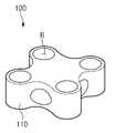
도 1에 도시된 바와 같이 본 발명에 따른 유전자 증폭 모듈은 열블록(100)을 포함할 수 있다.As shown in FIG. 1, the gene amplification module according to the present invention may include a
열블록(100)은 증폭하고자 하는 시료를 수용하는 구성일 수 있다. 열블록(100)의 열전달에 의해 주기적으로 가열 및 냉각됨으로써 열블록(100)에 수용된 시료의 유전자가 증폭될 수 있다. 가열 및 냉각 과정에서 효율적인 열 전달을 위해 열블록(100)은 금, 은, 구리, 합금 등의 열전도성이 높은 물질로 제조될 수 있다. 예를 들어, 열블록(100)은 알루미늄으로 제조될 수 있다.The
이를 위해, 도 1에 도시된 바와 같이 열블록(100)에는 증폭하고자 하는 시료가 구비된 반응용기(미도시)가 수용되기 위한 반응용기 수용공간(R)이 형성될 수 있다. 도 1에는 열블록(100)에 2×2의 행렬 형태로 총 4개의 반응용기 수용공간(R)이 형성된 경우가 도시되어 있다. 그러나, 반응용기 수용공간(R)의 개수 또는 배치 구조는 도 1에 제한되지 않는다. 한편, 반응용기는 플라스틱 소재로 이루어질 수 있다.To this end, as shown in FIG. 1, the reaction block accommodating space R for accommodating a reaction vessel (not shown) provided with a sample to be amplified may be formed in the
계속해서 도 1을 참고하면 열블록(100)에는 열블록(100)의 둘레를 형성하는 측벽(110)이 형성될 수 있다. 도 1에는 4개의 측벽이 각각 물결 형상의 곡면으로 형성된 경우가 도시되어 있다. 열블록(100)의 측벽이 물결 형상의 곡면으로 제조되는 경우 4개의 평면이 서로 만나 열블록의 측벽을 형성하는 경우와 비교하였을 때, 열블록(100)의 무게가 최소화되므로, 열블록(100)의 열용량이 감소하여 열블록의 가열과 냉각 속도가 최소화될 수 있다. 그러나, 본 발명에 따른 열블록(100)의 둘레를 형성하는 측벽의 형상은 물결 형상 이외에도 다양한 형상을 가질 수 있다. 즉, 본 발명에 따른 열블록(100)의 측벽의 형상이 물결 형상에 제한되는 것은 아니다.Subsequently, referring to FIG. 1, the
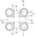
한편, 열블록(100)의 측벽에는 적어도 하나 이상의 홀이 형성될 수 있다. 열블록(100)에 형성된 홀은 가열된 열블록(100)을 냉각하기 위한 냉각용 유체가 공급 및 배출되기 위한 구성일 수 있다. 도 1 및 도 2에 도시된 바와 같이, 열블록(100)의 측벽들(110) 중 일부에는 냉각용 유체가 공급되는 공급홀(SH)이 형성될 수 있고, 열블록(100)의 측벽들(110) 중 다른 일부에는 냉각용 유체가 외부로 배출될 수 있는 배출홀(DH)이 형성될 수 있다. 이때, 냉각용 유체는 기체일 수 있다. 예를 들어, 냉각용 유체는 상온의 공기일 수 있다.Meanwhile, at least one hole may be formed in the sidewall of the
계속해서 도 2를 참고하면, 열블록(100)의 내부에는 빈 공간(V)이 형성될 수 있다. 빈 공간(V)은 공급홀(SH) 및 배출홀(DH)과 연결될 수 있다. 따라서, 빈 공간(V)은 열블록(100)에 공급된 냉각용 유체가 유동하는 경로를 제공할 수 있다.2, an empty space V may be formed inside the
한편, 공급홀(SH)은 두 개가 형성될 수 있는데, 이때, 공급홀(SH)들은 빈 공간(V)을 사이에 두고 서로 반대편에 형성될 수 있다.On the other hand, two supply holes (SH) may be formed, in this case, the supply holes (SH) may be formed on the opposite side with the empty space (V) in between.
도 2에 도시된 바와 같이, 열블록(100)에 형성된 빈 공간(V)은 반응용기 수용공간(R)과 연결되지 않고 반응용기 수용공간(R)으로부터 이격되도록 형성될 수 있다.As shown in FIG. 2, the empty space V formed in the
전술한 바와 같이 반응용기 수용공간(R)에는 증폭하고자 하는 시료가 구비된 반응용기가 수용될 수 있는데, 반응용기 수용공간(R)과 빈 공간(V)이 서로 연결되는 경우 반응용기 수용공간(R)을 형성하는 내벽이 반응용기를 충분히 감싸지 못하게 된다. 이 경우, 시료가 열블록(100)에 의해 신속하게 가열 또는 냉각되지 못하게 되므로 시료의 증폭에 걸리는 시간이 증가하게 된다. 따라서, 본 발명에 따르면 시료가 열블록(100)에 의해 신속하게 가열 또는 냉각될 수 있도록 반응용기 수용공간(R)은 빈 공간(V)과 연결되지 않는 것이 바람직할 수 있다.As described above, the reaction vessel accommodating space R may contain a reaction vessel provided with a sample to be amplified. When the reaction vessel accommodating space R and the empty space V are connected to each other, the reaction vessel accommodating space ( The inner wall forming R) does not sufficiently wrap the reaction vessel. In this case, the sample is not quickly heated or cooled by the
또한, 도 2에 도시된 바와 같이 열블록(100)의 내부에 형성된 빈 공간(V)은 제1 빈 공간(V1)과 제2 빈 공간(V2)을 포함할 수 있다. 이 중 제1 빈 공간(V1)의 양끝부는 각각 공급홀(SH)과 연결될 수 있다. 또한, 제2 빈 공간(V2)은 제1 빈 공간(V1)과 교차하여 형성될 수 있다.In addition, as shown in FIG. 2, the empty space V formed inside the
한편, 열블록(100)의 측벽에는 공급홀(SH) 이외에도 홀들이 더 형성될 수 있다. 즉, 도 2에 도시된 바와 같이 열블록(100)의 측벽에는 배출홀(DH)이 더 형성될 수 있다. 도 2에는 도 2를 기준으로 열블록(100)의 좌우에 형성된 측벽에 각각 배출홀(DH)이 하나씩 형성된 경우가 도시되어 있다. 배출홀(DH)은 제2 빈 공간(V2)와 연결될 수 있다. 또한, 배출홀(DH) 역시 복수로 구비될 수 있는데, 예를 들어, 도 2에 도시된 바와 같이 배출홀(DH)은 제2 빈 공간(V2)의 양끝부에 각각 형성될 수 있다.Meanwhile, holes may be further formed on the sidewall of the
한편, 도 3에 도시된 바와 같이 본 발명에 따른 유전자 증폭 모듈은, 열블록(100)의 측벽들 중 하나와 마주보도록 구비되고, 열블록(100)에 냉각용 유체를 공급하는 유체 공급부(400)을 더 포함할 수 있다. 유체 공급부(400)는 공급홀(SH, 도 2 참조)이 형성된 측벽과 마주볼 수 있다. 따라서, 유체 공급부(400)는 공급홀을 통해 열블록(100) 내부의 빈 공간(V, 도 2 참조)에 냉각용 유체를 공급할 수 있다.Meanwhile, as shown in FIG. 3, the gene amplification module according to the present invention is provided to face one of the sidewalls of the
계속해서 도 3을 참고하면, 본 발명에 따른 유전자 증폭 모듈의 유체 공급부(400)는 복수로 구비될 수 있다. 유체 공급부(400)는 공급홀(SH, 도 2 참조)의 개수만큼 구비될 수 있다. 도 3에는 열블록(100)에 형성된 2개의 공급홀 중 하나가 형성되는 열블록(100)의 측벽과 마주보도록 구비되는 제1 유체 공급부(410) 및 열블록(100)에 형성된 2개의 공급홀 중 다른 하나가 형성되는 열블록(100)의 측벽과 마주보도록 구비되는 제2 유체 공급부(420)가 도시되어 있다.3, the
한편, 본 발명에 따른 유체 공급부(400)는 냉각용 유체가 열블록(100)의 빈 공간 내에 공급될 수 있도록 회전 가능한 팬(fan)을 포함할 수 있다.On the other hand, the
도 3에 도시된 바와 같이 유체 공급부(400)는 공급홀(SH, 도 2 참조)이 형성되는 측벽에 밀착 구비될 수 있다. 따라서, 냉각용 유체가 유체 공급부(400)에서 열블록(100) 이외에 다른 곳으로 누출되는 것을 최소화할 수 있다.As shown in FIG. 3, the
한편, 전술한 바와 같이 열블록(100)에는 공급홀 및 배출홀(SH 및 DH, 도 2 참조)이 형성될 수 있는데, 유전자 증폭 모듈은, 배출홀과 마주보도록 구비되고, 배출홀을 통해 열블록(100) 내 냉각용 유체를 외부로 배출하는 유체 배출부(미도시)를 더 포함할 수 있다.Meanwhile, as described above, the supply block and the discharge hole (SH and DH, see FIG. 2) may be formed in the
도 4는 본 발명에 따른 유전자 증폭 모듈의 구조를 도시한 사시도이다.Figure 4 is a perspective view showing the structure of a gene amplification module according to the present invention.
전술한 바와 같이 본 발명에 따른 유전자 증폭 모듈(10)은 열블록(100) 및 유체 공급부(400)를 포함할 수 있다.As described above, the
또한, 본 발명에 따른 유전자 증폭 모듈(10)은 열블록(100)의 하부에 구비되고 열블록(100)을 가열하는 가열부(200)를 포함할 수 있다. 가열부(200)는 열블록(100)과 접촉할 수 있다. 따라서, 가열부(200)는 열블록(100)과 열전도에 의한 열교환을 할 수 있다. 본 발명에 따른 가열부(200)는 펠티어 효과(peltier effect)에 의한 국부적인 온도 상승으로 열블록(100)을 가열하는 구성일 수 있다.In addition, the
펠티어 효과는 물체의 양쪽에 전압을 걸면 전류와 함께 열 에너지가 이동하게 됨으로써 양쪽에 온도 차이가 발생하는 현상을 의미한다. 본 발명에 따른 가열부는 이러한 펠티어 효과를 통해 열블록을 가열하는 구성일 수 있다.The Peltier effect refers to a phenomenon in which a temperature difference occurs on both sides by applying a voltage to both sides of an object, which causes thermal energy to move with current. The heating unit according to the present invention may be configured to heat the heat block through the Peltier effect.
계속해서 도 4를 참고하면, 본 발명에 따른 유전자 증폭 모듈(10)은 가열부(200)의 하부에 구비되고, 열블록(100)을 냉각하는 냉각부(300)를 더 포함할 수 있다. 냉각부(300)는 가열부(200)와 접촉할 수 있다. 따라서, 냉각부(300)와 가열부(200) 간의 열전도에 의한 열교환 및 가열부(200)와 열블록(100) 간의 열교환에 의해 냉각부(300)는 열블록(100)을 냉각할 수 있다. 즉, 본 발명에 따른 냉각부(300)는 열블록(100) 및 가열부(200)에 비해 온도가 낮고 열용량이 현저하게 큰 방열체(heat sink)일 수 있다.Subsequently, referring to FIG. 4, the
이하, 전술한 내용 및 도면을 토대로 본 발명에 따른 유전자 증폭 모듈(10)의 작동 방식을 설명하면 다음과 같다.Hereinafter, the operation of the
열블록(100)의 반응용기 수용공간(R)의 내부에 시료가 구비된 반응용기를 배치한 후 가열부(200)를 작동하여 가열부(200)의 온도가 상승하면, 열블록(100)과 가열부(200) 간의 열전도에 의한 열교환에 의해 열블록(100)의 온도가 상승하게 되고, 그에 따라 반응용기 내 시료의 온도 역시 상승하게 된다.After placing the reaction vessel provided with a sample inside the reaction vessel accommodating space (R) of the
시료의 온도가 일정 값에 도달하면 가열부(200)의 작동을 중단한다. 따라서, 냉각부(300)와 가열부(200) 간의 열전도에 의한 열교환과 가열부(200)와 열블록(100) 간의 열전도에 의한 열교환에 의해 열블록(100)의 온도가 하강하게 되고 그에 따라 반응용기 내 시료의 온도 역시 하강하게 된다.When the temperature of the sample reaches a predetermined value, the operation of the
특히, 본 발명에 따르면 냉각부(300)의 가동과 함께 유체 공급부(400)를 통해 냉각용 유체가 열블록(100)의 공급홀(SH)을 통해 열블록(100)의 빈 공간(V)에 냉각용 유체가 공급되므로 냉각용 유체가 열블록(100)을 추가로 냉각할 수 있게 되어, 열블록(100) 및 시료의 냉각이 보다 신속하게 이루어질 수 있고, 시료의 증폭 과정에 필요한 전체적인 시간 역시 현저하게 감소할 수 있다.Particularly, according to the present invention, the cooling fluid flows through the
도 5는 본 발명에 따른 유전자 증폭 모듈의 열블록의 구조의 다른 예를 도시한 사시도이고, 도 6은 본 발명에 따른 유전자 증폭 모듈의 열블록의 구조의 다른 예를 도시한 수평 단면도이다.5 is a perspective view showing another example of the structure of the column block of the gene amplification module according to the present invention, Figure 6 is a horizontal cross-sectional view showing another example of the structure of the column block of the gene amplification module according to the present invention.
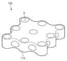
전술한 바와 같이 본 발명에 따른 열블록에는 2×2의 행렬 형태로 총 4개의 반응용기 수용공간이 형성될 수 있다. 그러나, 열블록은 이와는 다른 구조를 가질 수 있다. 예를 들어, 도 5 및 도 6에 도시된 바와 같이 본 발명에 따른 유전자 증폭 모듈의 열블록(100)에는 3×3의 행렬 형태로 총 9개의 반응용기 수용공간(R)이 형성될 수 있다. 또는, 열블록(100)에는 4×4의 행렬 형태로 총 9개의 반응용기 수용공간(R)이 형성될 수도 있다. 이를 일반화하면, 본 발명에 따른 유전자 증폭 모듈의 열블록(100)에는 n×n의 행렬 형태로 총 n2개의 반응용기 수용공간이 형성될 수 있다.As described above, a total of four reaction vessel accommodation spaces may be formed in a column block according to the present invention in a matrix form of 2 × 2. However, the thermal block may have a different structure. For example, as shown in FIGS. 5 and 6, a total of nine reaction vessel accommodation spaces R may be formed in a
또는, 본 발명에 따른 유전자 증폭 모듈의 열블록에는 m×n(m, n은 서로 다른 자연수)의 행렬 형태로 총 m×n개의 반응용기 수용공간이 형성될 수도 있다. 예를 들어, 열블록에는 2×3의 행렬 형태로 총 6개의 반응용기 수용공간이 형성될 수 있다.Alternatively, a total of m × n reaction vessel accommodation spaces may be formed in a column block of the gene amplification module according to the present invention in a matrix form of m × n (m, n is a different natural number). For example, a total of six reaction vessel accommodation spaces may be formed in a column block in the form of a 2 × 3 matrix.
계속해서 도 5 및 도 6을 참고하면, 열블록(100)의 둘레를 형성하는 측벽들에는 각각 복수의 공급홀(SH) 및 배출홀(DH)이 형성될 수 있다. 예를 들어, 도 6에 도시된 바와 같이 열블록(100)에 3×3의 행렬 형태로 총 9개의 반응용기 수용공간(R)이 형성되는 경우, 열블록(100)의 내부에 형성되는 제1 빈 공간(V1)을 사이에 두고 서로 반대편에 형성되는 두 측벽에는 각각 2개의 공급홀(SH)이 형성되어, 열블록(100)에는 총 4개의 공급홀(SH)이 형성될 수 있다. 이와 유사하게, 도 6에 도시된 바와 같이 열블록(100)에 3×3의 행렬 형태로 총 9개의 반응용기 수용공간(R)이 형성되는 경우, 열블록(100)의 내부에 형성되는 제2 빈 공간(V2)을 사이에 두고 서로 반대편에 형성되는 다른 두 측벽에는 각각 2개의 배출홀(DH)이 형성되어, 열블록(100)에는 총 4개의 배출홀(DH)이 형성될 수 있다. 이를 일반화하면, 본 발명에 따른 유전자 증폭 모듈의 열블록에 n×n의 행렬 형태로 총 n2개의 반응용기 수용공간이 형성되는 경우, 열블록의 제1 빈 공간을 사이에 두고 서로 반대편에 형성되는 두 측벽에는 각각 n-1개의 공급홀이 형성되어, 열블록에는 총 2× (n-1)개의 공급홀이 형성될 수 있다. 이와 유사하게, 본 발명에 따른 유전자 증폭 모듈의 열블록에 n×n의 행렬 형태로 총 n2개의 반응용기 수용공간이 형성되는 경우, 열블록의 제2 빈 공간을 사이에 두고 서로 반대편에 형성되는 두 측벽에는 각각 n-1개의 배출홀이 형성되어, 열블록에는 총 2×(n-1)개의 배출홀이 형성될 수 있다.5 and 6, a plurality of supply holes SH and discharge holes DH may be formed in sidewalls forming the circumference of the
한편, 전술한 바와 같이, 본 발명에 따른 유전자 증폭 모듈의 열블록에는 m×n(m, n은 서로 다른 자연수)의 행렬 형태로 총 m×n개의 반응용기 수용공간이 형성될 수 있는데, 이 경우, 열블록의 제1 빈 공간을 사이에 두고 서로 반대편에 있는 두 측벽에는 각각 m-1개의 공급홀이 형성되어, 열블록에는 총 2×(m-1)개의 공급홀이 형성될 수 있고, 열블록의 제2 빈 공간을 사이에 두고 서로 반대편에 있는 두 측벽에는 각각 n-1개의 배출홀이 형성되어, 열블록에는 총 2×(n-1)개의 배출홀이 형성될 수 있다.On the other hand, as described above, in the column block of the gene amplification module according to the present invention, a total m × n reaction vessel accommodation space may be formed in a matrix form of m × n (m, n is a different natural number). In this case, m-1 supply holes may be formed in two sidewalls opposite to each other with the first empty space of the thermal block interposed therebetween, and a total of 2 × (m-1) supply holes may be formed in the thermal block. In addition, n-1 discharge holes may be formed in the two sidewalls opposite to each other with the second empty space of the thermal block interposed therebetween, and a total of 2 × (n-1) discharge holes may be formed in the thermal block.
열블록에 m×n의 행렬 형태로 총 m×n개의 반응용기 수용공간이 형성되는 경우, 열블록의 제1 빈 공간을 사이에 두고 서로 반대편에 있는 두 측벽에는 각각 m-1개의 공급홀이 형성되고 열블록의 제2 빈 공간을 사이에 두고 서로 반대편에 있는 두 측벽에는 각각 n-1개의 배출홀이 형성되는 것은, 도 5 및 도 6에 도시된 바와 같이 공급홀(SH)들과 배출홀(DH)들이 각각 반응용기 수용공간(R)들 사이에 형성되기 때문일 수 있다.When a total of m × n reaction vessel accommodating spaces are formed in an m × n matrix in a column block, m-1 supply holes are provided on two side walls opposite to each other with a first empty space of the column block therebetween. And n-1 discharge holes are formed in the two sidewalls opposite to each other with the second empty space of the thermal block interposed therebetween, as shown in FIGS. 5 and 6, the supply holes SH and the discharge holes. The holes DH may be formed between the reaction vessel receiving spaces R, respectively.
또한, 도 5 및 도 6에 도시된 바와 같이 제1 빈 공간(V1)을 사이에 두고 서로 반대편에 형성된 공급홀(SH)들과, 제2 빈 공간(V2)을 사이에 두고 서로 반대편이 형성된 배출홀(DH)들은 각각 제1 빈 공간(V1)과 제2 빈 공간(V2)과 연결될 수 있다.In addition, as shown in FIGS. 5 and 6, supply holes SH formed on opposite sides with the first empty space V1 interposed therebetween, and opposite sides formed with the second empty space V2 interposed therebetween. The discharge holes DH may be connected to the first empty space V1 and the second empty space V2, respectively.
실시예 1Example 1
가로 16mm, 세로 16mm의 열블록을 제조하였다. 열블록의 네 측벽은 각각 물결 형상의 곡면으로 형성되었고, 열블록에는 2×2의 행렬 형태로 총 4개의 반응용기 수용공간이 형성되었다. 반응용기 수용공간의 직경은 각각 4.5mm로 형성되었다. 열블록은 알루미늄으로 제작되었다.16 mm wide and 16 mm long thermal blocks were prepared. The four sidewalls of the column blocks were each formed of wavy curved surfaces, and a total of four reaction vessel receiving spaces were formed in the column block in a 2 × 2 matrix form. The diameter of the reaction vessel receiving space was formed to each 4.5mm. The thermal block is made of aluminum.
열블록의 네 측벽에는 각각 4.8mm의 직경을 갖는 홀들이 하나씩 형성되었고, 열블록의 내부에는 십(十)자 형태의 빈 공간이 형성되었다. 빈 공간에 의해 각 홀들이 서로 연결되었다.Four sidewalls of the thermal block were formed with holes each having a diameter of 4.8 mm, and a hollow space having a cross shape was formed inside the thermal block. Each hole is connected to each other by an empty space.
열블록의 하부에는 열전소자인 펠티어 기반의 가열부가 밀착 구비되었다. 가열부는 펠티어 효과(peltier effect)에 의해 열블록을 가열하는 열전소자로서, 미국 TE technology, INC사에서 제조된 제품명 VT-127-1.4-1.15-71이 사용되었다.The lower part of the thermal block was provided with a Peltier-based heating unit that is a thermoelectric element. The heating unit is a thermoelectric element for heating the heat block by the peltier effect, and the product name VT-127-1.4-1.15-71 manufactured by TE technology, INC, USA was used.
가열부의 하부에는 냉각부가 밀착 구비되었다. 냉각부는 열을 흡수할 수 있는 방열체(heat sink)로 마련되었다. 방열체 하단에는 방열체의 온도를 낮추기 위한 송풍팬이 설치되었다. 방열체 및 송풍팬은 한국 Coolertech사에서 제조된 제품명 CTV-GF-04이 사용되었다.The cooling part was closely attached to the lower part of the heating part. The cooling unit is provided with a heat sink capable of absorbing heat. At the bottom of the heat sink, a blowing fan is installed to lower the temperature of the heat sink. As the heat sink and the blower fan, the product name CTV-GF-04 manufactured by Coolertech Co., Ltd. was used.
열블록의 네 측벽 중 서로 반대편에서 마주보는 두 측벽에는 유체 공급부가 밀착 구비되었다. 유체 공급부는 팬을 가동하여 냉각용 유체를 열블록의 빈 공간에 공급하는 구성으로서, 유체 공급부를 구성하는 팬은 중국 YeHAUS에서 제조된 제품명 HFD 0200605 SEM, B-type이 사용되었다.Two of the four sidewalls of the thermal block facing each other on the opposite side is provided with a fluid supply unit closely. The fluid supply unit is configured to supply a cooling fluid to the empty space of the heat block by operating the fan. The fan constituting the fluid supply unit is HFD 0200605 SEM, B-type manufactured by YeHAUS, China.
실시예 1에서는 가열부를 14.8V 및 5A의 전압 및 전류 하에 작동하여 열블록의 온도가 섭씨 95도에 도달할 때까지 가열한 후, 가열부의 작동을 중지시키고 11.1V, 0.28A 및 3.1W 하에 유체 공급부를 가동하여, 냉각용 유체 및 하단에 설치된 냉각부에 의해 열블록이 섭씨 60도에 도달할 때까지 냉각하였다. 특히, 냉각 과정에서는 방열체 하단에 설치된 송풍팬을 가동하여 방열체의 온도를 낮춤으로써 열블록과 방열체 사이에 구배를 발생하여 열블록을 냉각하였다. 상기 가열 과정과 냉각 과정을 반복하였다.In Example 1, the heating unit was operated under voltage and current of 14.8 V and 5 A to heat until the temperature of the heat block reached 95 degrees Celsius, after which the heating unit was stopped and the fluid under 11.1 V, 0.28 A and 3.1 W The supply unit was operated to cool the thermal block until it reached 60 degrees Celsius by the cooling fluid and the cooling unit provided at the bottom. In particular, in the cooling process, by operating a blower fan installed at the bottom of the heat sink to lower the temperature of the heat sink, a gradient is generated between the heat block and the heat sink to cool the heat block. The heating and cooling processes were repeated.
실시예 2Example 2
유체 공급부를 7.4V, 0.21V 및 1.5W 하에 작동하여 열블록의 온도를 섭씨 60도에 도달할 때까지 냉각하는 것을 제외하고는 실시예 1과 동일하게 진행하였다.The fluid supply was operated in the same manner as in Example 1 except that the fluid supply was operated under 7.4 V, 0.21 V and 1.5 W to cool the temperature of the heat block until it reached 60 degrees Celsius.
비교예Comparative example
유체 공급부를 구비하지 않은 것을 제외하고는 실시예 1과 동일하게 진행하였다.The same procedure as in Example 1 was conducted except that the fluid supply unit was not provided.
실험예Experimental Example
실시예와 비교예에 따라 30번의 가열 과정 및 냉각 과정을 완료하는데 걸린 시간을 측정하였다.According to the Examples and Comparative Examples, the time taken to complete 30 heating and cooling processes was measured.
실시예 1의 경우 30번의 가열 과정 및 냉각 과정을 완료하는데 602초가 소요되었고, 실시예 2의 경우 674초가 소요되었다. 비교예의 경우 840초가 소요되었다.In the case of Example 1, it took 602 seconds to complete 30 heating and cooling processes, and 674 seconds in Example 2. The comparative example took 840 seconds.
실험 결과에서도 확인할 수 있듯, 실시예 1 및 실시예 2에 따라 열블록의 빈 공간에 냉각용 유체를 공급하는 경우, 그렇지 않은 경우와 비교하여 가열 과정 및 냉각 과정이 이루어지는 데 걸리는 시간이 현저하게 감소하였음을 확인할 수 있다. 예를 들어, 비교예와 비교하여 실시예 1의 경우 가열 과정 및 냉각 과정이 완료되는 데 걸리는 시간이 약 30%가 감소한 것을 확인할 수 있다.As can be seen from the experimental results, when the cooling fluid is supplied to the empty space of the heat block according to Examples 1 and 2, the time required for the heating process and the cooling process to be significantly reduced is compared with the case where it is not. It can be confirmed that. For example, compared to the comparative example, it can be seen that in Example 1, the time taken to complete the heating process and the cooling process is reduced by about 30%.
이상에서 본 발명은 비록 한정된 실시예와 도면에 의해 설명되었으나, 본 발명은 이것에 의해 한정되지 않으며, 본 발명이 속하는 기술분야에서 통상의 지식을 가진 자에 의해 본 발명의 기술사상과 아래에 기재될 특허청구범위의 균등범위 내에서 다양한 실시가 가능함은 물론이다.Although the present invention has been described above by means of limited embodiments and drawings, the present invention is not limited thereto, and the technical concept of the present invention and the following will be described by those skilled in the art to which the present invention pertains. Of course, various implementations are possible within the scope of equivalent claims.
10 : 유전자 증폭 모듈
100 : 열블록
110 : 측벽
200 : 가열부
300 : 냉각부
400 : 유체 공급부
410 : 제1 유체 공급부
420 : 제2 유체 공급부
R : 반응용기 수용공간
SH : 공급홀
DH : 배출홀
V1 : 제1 빈 공간
V2 : 제2 빈 공간10: gene amplification module
100: heat block
110: sidewall
200: heating unit
300: cooling unit
400: fluid supply
410: first fluid supply portion
420: second fluid supply unit
R: space for reaction vessel
SH: supply hole
DH: discharge hole
V1: first empty space
V2: second empty space
Claims (10)
Translated fromKorean증폭하고자 하는 시료가 구비된 반응용기가 수용되기 위한 반응용기 수용공간이 형성되는 열블록;
상기 열블록의 하부에 구비되고, 상기 열블록과 열전도에 의한 열교환에 의해 상기 열블록을 가열하는 가열부;
상기 가열부의 하부에 구비되고, 상기 가열부와 열전도에 의한 열교환에 의해 상기 열블록을 냉각하는 냉각부; 및
상기 열블록의 일측과 마주보도록 구비되고, 상기 열블록에 냉각용 유체를 공급하는 유체 공급부; 를 포함하고,
상기 열블록에는 상기 열블록의 둘레를 형성하는 측벽이 형성되고,
상기 측벽에는 상기 냉각용 유체가 공급될 수 있는 공급홀이 하나 이상 형성되고,
상기 냉각부는 방열체(heat sink)이고,
상기 열블록의 상기 측벽에는 만입된 형상의 만입부가 형성되고,
상기 유체 공급부는,
상기 공급홀이 형성되는 상기 열블록의 측벽과 마주보도록 구비되는 제1 유체 공급부; 및
상기 공급홀이 형성되는 열블록의 다른 측벽과 마주보도록 구비되고, 상기 열블록을 사이에 두고 상기 제1 유체 공급부와 서로 마주보는 제2 유체 공급부; 를 포함하는 유전자 증폭 모듈.As a gene amplification module,
A heat block in which a reaction vessel accommodating space for accommodating a reaction vessel provided with a sample to be amplified is formed;
A heating unit provided below the thermal block and heating the thermal block by heat exchange with the thermal block;
A cooling unit provided below the heating unit and cooling the thermal block by heat exchange with the heating unit; And
A fluid supply unit provided to face one side of the thermal block and supplying a cooling fluid to the thermal block; Including,
The column block is formed with sidewalls forming the periphery of the column block,
At least one supply hole may be formed in the side wall to supply the cooling fluid.
The cooling unit is a heat sink,
An indentation of indented shape is formed in the sidewall of the thermal block,
The fluid supply unit,
A first fluid supply part provided to face a side wall of the thermal block in which the supply hole is formed; And
A second fluid supply part provided to face another side wall of the heat block in which the supply hole is formed, and facing the first fluid supply part with the heat block therebetween; Gene amplification module comprising a.
상기 열블록의 내부에는 빈 공간이 형성되고,
상기 빈 공간은 상기 공급홀과 연결되는 유전자 증폭 모듈.In claim 1,
An empty space is formed inside the thermal block,
The empty space is a gene amplification module connected to the supply hole.
상기 열블록에는 m×n(m, n은 서로 다른 자연수)의 행렬 형태로 총 m×n개의 상기 반응용기 수용공간이 형성되고,
상기 공급홀은 각각 반응용기 수용공간들 사이에 형성되는 유전자 증폭 모듈.In claim 2,
In the column block, a total of m × n reaction container accommodating spaces are formed in a matrix form of m × n (m and n are different natural numbers),
Each of the supply holes is a gene amplification module formed between the reaction vessel receiving spaces.
상기 유체 공급부는 상기 측벽 중 상기 공급홀이 형성되는 측벽에 밀착 구비되는 유전자 증폭 모듈.In claim 1,
The fluid supply unit is a gene amplification module provided in close contact with the side wall in which the supply hole is formed.
상기 빈 공간은 상기 반응용기 수용공간과 연결되지 않고 상기 반응용기 수용공간으로부터 이격되어 있는 유전자 증폭 모듈.In claim 2,
The empty space is not connected to the reaction vessel receiving space gene amplification module spaced apart from the reaction vessel receiving space.
상기 빈 공간은,
상기 공급홀과 연결되는 제1 빈 공간; 및
상기 제1 빈 공간과 교차하여 형성되는 제2 빈 공간; 을 포함하는 유전자 증폭 모듈.In claim 3,
The empty space,
A first empty space connected to the supply hole; And
A second empty space formed to intersect the first empty space; Gene amplification module comprising a.
상기 열블록의 측벽에는 상기 제2 빈 공간과 연결되는 배출홀이 형성되는 유전자 증폭 모듈.In claim 7,
Gene side amplification module is formed in the side wall of the heat block and the discharge hole connected to the second empty space.
상기 배출홀은 상기 제2 빈 공간의 양끝부에 각각 형성되는 유전자 증폭 모듈.In claim 8,
The discharge hole is a gene amplification module respectively formed at both ends of the second empty space.
상기 유체 공급부는,
상기 냉각용 유체가 상기 열블록의 빈 공간 내에 공급될 수 있도록 회전 가능한 팬(fan); 을 포함하는 유전자 증폭 모듈.In claim 2,
The fluid supply unit,
A fan rotatable such that the cooling fluid can be supplied into the empty space of the heat block; Gene amplification module comprising a.
Priority Applications (6)
| Application Number | Priority Date | Filing Date | Title |
|---|---|---|---|
| KR1020190006143AKR102009505B1 (en) | 2019-01-17 | 2019-01-17 | Module for polymerase chain reaction of sample |
| US17/423,291US12427525B2 (en) | 2019-01-17 | 2020-01-07 | Gene amplification module |
| EP20740902.0AEP3903939A4 (en) | 2019-01-17 | 2020-01-07 | GENE AMPLIFICATION MODULE |
| PCT/KR2020/000289WO2020149559A1 (en) | 2019-01-17 | 2020-01-07 | Gene amplification module |
| CN202080007358.0ACN113272064B (en) | 2019-01-17 | 2020-01-07 | Gene amplification module |
| JP2021541501AJP2022530178A (en) | 2019-01-17 | 2020-01-07 | Gene amplification module |
Applications Claiming Priority (1)
| Application Number | Priority Date | Filing Date | Title |
|---|---|---|---|
| KR1020190006143AKR102009505B1 (en) | 2019-01-17 | 2019-01-17 | Module for polymerase chain reaction of sample |
Publications (1)
| Publication Number | Publication Date |
|---|---|
| KR102009505B1true KR102009505B1 (en) | 2019-08-12 |
Family
ID=67624842
Family Applications (1)
| Application Number | Title | Priority Date | Filing Date |
|---|---|---|---|
| KR1020190006143AActiveKR102009505B1 (en) | 2019-01-17 | 2019-01-17 | Module for polymerase chain reaction of sample |
Country Status (6)
| Country | Link |
|---|---|
| US (1) | US12427525B2 (en) |
| EP (1) | EP3903939A4 (en) |
| JP (1) | JP2022530178A (en) |
| KR (1) | KR102009505B1 (en) |
| CN (1) | CN113272064B (en) |
| WO (1) | WO2020149559A1 (en) |
Cited By (3)
| Publication number | Priority date | Publication date | Assignee | Title |
|---|---|---|---|---|
| WO2020149559A1 (en)* | 2019-01-17 | 2020-07-23 | 주식회사 엘지화학 | Gene amplification module |
| KR20210054795A (en)* | 2019-11-06 | 2021-05-14 | 주식회사 유진셀 | Cooling module of pcr amplification reaction apparatus |
| WO2022114814A1 (en)* | 2020-11-26 | 2022-06-02 | Seegene, Inc. | Thermal module and method of operating same |
Citations (2)
| Publication number | Priority date | Publication date | Assignee | Title |
|---|---|---|---|---|
| WO2008035074A2 (en)* | 2006-09-19 | 2008-03-27 | Bg Research Ltd. | Improvements in reaction apparatus |
| KR20140134435A (en)* | 2013-05-14 | 2014-11-24 | (주)마이크로디지탈 | Polymerase chain reaction system |
Family Cites Families (48)
| Publication number | Priority date | Publication date | Assignee | Title |
|---|---|---|---|---|
| US4865986A (en) | 1988-10-06 | 1989-09-12 | Coy Corporation | Temperature control apparatus |
| US4950608A (en) | 1989-04-25 | 1990-08-21 | Scinics Co., Ltd. | Temperature regulating container |
| KR100236506B1 (en) | 1990-11-29 | 2000-01-15 | 퍼킨-엘머시터스인스트루먼츠 | Apparatus for polymerase chain reaction |
| JPH05168459A (en)* | 1991-12-20 | 1993-07-02 | Orion Mach Co Ltd | Device for heating and cooling nucleic acid amplifier |
| JP2547970B2 (en)* | 1994-06-13 | 1996-10-30 | 株式会社日本医化器械製作所 | Constant temperature bath device |
| JPH08117590A (en) | 1994-10-20 | 1996-05-14 | Sanyo Electric Co Ltd | Temperature cycle apparatus |
| US8293064B2 (en) | 1998-03-02 | 2012-10-23 | Cepheid | Method for fabricating a reaction vessel |
| US6171850B1 (en)* | 1999-03-08 | 2001-01-09 | Caliper Technologies Corp. | Integrated devices and systems for performing temperature controlled reactions and analyses |
| US6657169B2 (en) | 1999-07-30 | 2003-12-02 | Stratagene | Apparatus for thermally cycling samples of biological material with substantial temperature uniformity |
| US6337435B1 (en) | 1999-07-30 | 2002-01-08 | Bio-Rad Laboratories, Inc. | Temperature control for multi-vessel reaction apparatus |
| DE29917313U1 (en) | 1999-10-01 | 2001-02-15 | MWG-BIOTECH AG, 85560 Ebersberg | Device for carrying out chemical or biological reactions |
| FR2812306B1 (en)* | 2000-07-28 | 2005-01-14 | Gabriel Festoc | POLYMERSIS CHAIN AMPLIFICATION SYSTEM OF TARGET NUCLEIC SEQUENCES |
| KR20020017212A (en) | 2000-08-29 | 2002-03-07 | 장기영 | Thermal cycler |
| US8900811B2 (en)* | 2000-11-16 | 2014-12-02 | Caliper Life Sciences, Inc. | Method and apparatus for generating thermal melting curves in a microfluidic device |
| KR100488281B1 (en) | 2001-09-15 | 2005-05-10 | 아람 바이오시스템 주식회사 | Method and apparatus for amplification of nucleic acid sequences by using thermal convection |
| US20070184548A1 (en)* | 2002-12-23 | 2007-08-09 | Lim Hi Tan | Device for carrying out chemical or biological reactions |
| US7604965B2 (en)* | 2003-04-03 | 2009-10-20 | Fluidigm Corporation | Thermal reaction device and method for using the same |
| US7170594B2 (en)* | 2003-05-28 | 2007-01-30 | Smiths Detection, Inc. | Device for polymerase chain reactions |
| KR100519343B1 (en)* | 2003-07-02 | 2005-10-07 | 엘지전자 주식회사 | wearable cooler |
| JP2005261260A (en)* | 2004-03-17 | 2005-09-29 | Fuji Electric Holdings Co Ltd | Microorganism or cell inspection apparatus and inspection method |
| DE102004034827A1 (en)* | 2004-07-19 | 2006-03-16 | Fraunhofer-Gesellschaft zur Förderung der angewandten Forschung e.V. | Cooling device for biological samples |
| US7659110B2 (en)* | 2005-01-21 | 2010-02-09 | Thermogen Inc. | DNA amplification device |
| JP4464869B2 (en)* | 2005-01-21 | 2010-05-19 | 長野県 | DNA amplification equipment |
| JP4756880B2 (en)* | 2005-03-02 | 2011-08-24 | キヤノン株式会社 | PCR reaction temperature controller |
| EP1710017B1 (en)* | 2005-04-04 | 2012-12-19 | Roche Diagnostics GmbH | Thermocycling of a block comprising multiple samples |
| RU59785U1 (en)* | 2006-05-22 | 2006-12-27 | Закрытое акционерное общество Научно-производственное общество "Машпром" (ЗАО НПП "Машпром") | TWO FLOW BLOCK HEAT EXCHANGER |
| GB0718250D0 (en) | 2007-08-29 | 2007-10-31 | B G Res Ltd | Improvements in and relating to reaction apparatus |
| GB0704490D0 (en)* | 2007-03-08 | 2007-04-18 | Bg Res Ltd | Improvements in thermal cyclers |
| EP2137319B1 (en)* | 2007-03-21 | 2018-07-25 | Applied Biosystems, LLC | Adaptive thermal block temperature control method and system |
| US8141623B2 (en)* | 2007-05-01 | 2012-03-27 | Blecker Joseph G | Automatic switching two pipe hydronic system |
| KR100945556B1 (en) | 2007-10-25 | 2010-03-08 | 충청북도 | PCR based portable analysis device |
| CN101952412B (en)* | 2008-02-15 | 2014-07-23 | 生物辐射实验室股份有限公司 | Thermal cycler with self-adjusting lid |
| WO2009111696A1 (en) | 2008-03-06 | 2009-09-11 | Biotrove, Inc. | Devices and methods for thermally-mediated chemical reactions |
| KR20120022841A (en) | 2009-03-31 | 2012-03-12 | 카나가와 아카데미 오브 사이언스 앤드 테크놀로지 | Liquid reflux high-speed gene amplification device |
| CN102329725A (en)* | 2010-06-16 | 2012-01-25 | 三星泰科威株式会社 | Light transmittable temperature control device and polymerase chain reaction apparatus with the same |
| KR20120107716A (en) | 2011-03-22 | 2012-10-04 | 삼성테크윈 주식회사 | Temperature control apparatus for material |
| US9149809B2 (en)* | 2011-05-06 | 2015-10-06 | Bio-Rad Laboratories, Inc. | Thermal cycler with vapor chamber for rapid temperature changes |
| US20130137144A1 (en) | 2011-06-08 | 2013-05-30 | Bio-Rad Laboratories, Inc. LSG - GXD Division | Thermal block with built-in thermoelectric elements |
| AT511647B1 (en)* | 2011-07-08 | 2013-11-15 | Univ Wien Tech | FRIDGE / HEATING DEVICE |
| DE102011083555B4 (en)* | 2011-09-27 | 2013-10-10 | Aspre Ag | Analysis method and analyzer |
| DE102011119174A1 (en)* | 2011-11-23 | 2013-05-23 | Inheco Industrial Heating And Cooling Gmbh | Vapor Chamber |
| US9776182B2 (en) | 2012-11-27 | 2017-10-03 | Gencell Biosystems Ltd. | Handling liquid samples |
| CN105988002B (en)* | 2015-03-03 | 2021-01-19 | 江苏太和吉英医药科技有限公司 | Method for detecting endometrial receptivity by MST1 and phosphorylated MST1 |
| JP2017077208A (en)* | 2015-10-21 | 2017-04-27 | 株式会社エアレックス | incubator |
| US11123739B2 (en)* | 2016-04-15 | 2021-09-21 | Cbf Systems Inc. | Thermal cycling methods and apparatuses for carrying out efficient polymerase chain reaction (PCR) processes to amplify deoxyribonucleic acid (DNA) |
| WO2018139788A1 (en) | 2017-01-25 | 2018-08-02 | 주식회사 유진셀 | Apparatus for high-speed nucleic acid amplification and method for temperature control of nucleic acid amplification reaction |
| KR102039785B1 (en) | 2017-02-03 | 2019-11-04 | 주식회사 유진셀 | Method of controlling reaction temperature in nucleic acid amplification reaction |
| KR102009505B1 (en)* | 2019-01-17 | 2019-08-12 | 주식회사 엘지화학 | Module for polymerase chain reaction of sample |
- 2019
- 2019-01-17KRKR1020190006143Apatent/KR102009505B1/enactiveActive
- 2020
- 2020-01-07JPJP2021541501Apatent/JP2022530178A/enactivePending
- 2020-01-07CNCN202080007358.0Apatent/CN113272064B/enactiveActive
- 2020-01-07USUS17/423,291patent/US12427525B2/enactiveActive
- 2020-01-07WOPCT/KR2020/000289patent/WO2020149559A1/ennot_activeCeased
- 2020-01-07EPEP20740902.0Apatent/EP3903939A4/enactivePending
Patent Citations (2)
| Publication number | Priority date | Publication date | Assignee | Title |
|---|---|---|---|---|
| WO2008035074A2 (en)* | 2006-09-19 | 2008-03-27 | Bg Research Ltd. | Improvements in reaction apparatus |
| KR20140134435A (en)* | 2013-05-14 | 2014-11-24 | (주)마이크로디지탈 | Polymerase chain reaction system |
Cited By (5)
| Publication number | Priority date | Publication date | Assignee | Title |
|---|---|---|---|---|
| WO2020149559A1 (en)* | 2019-01-17 | 2020-07-23 | 주식회사 엘지화학 | Gene amplification module |
| US12427525B2 (en) | 2019-01-17 | 2025-09-30 | Invitros Co., Ltd. | Gene amplification module |
| KR20210054795A (en)* | 2019-11-06 | 2021-05-14 | 주식회사 유진셀 | Cooling module of pcr amplification reaction apparatus |
| KR102339885B1 (en) | 2019-11-06 | 2021-12-16 | 주식회사 유진셀 | Cooling module of pcr amplification reaction apparatus |
| WO2022114814A1 (en)* | 2020-11-26 | 2022-06-02 | Seegene, Inc. | Thermal module and method of operating same |
Also Published As
| Publication number | Publication date |
|---|---|
| US12427525B2 (en) | 2025-09-30 |
| EP3903939A1 (en) | 2021-11-03 |
| WO2020149559A1 (en) | 2020-07-23 |
| CN113272064B (en) | 2023-03-31 |
| JP2022530178A (en) | 2022-06-28 |
| US20220080426A1 (en) | 2022-03-17 |
| CN113272064A (en) | 2021-08-17 |
| EP3903939A4 (en) | 2022-02-23 |
Similar Documents
| Publication | Publication Date | Title |
|---|---|---|
| KR102009505B1 (en) | Module for polymerase chain reaction of sample | |
| JP3511007B2 (en) | Apparatus for fluid impingement thermal cycler, method of circulating a plurality of samples between at least two different temperatures using the same, and method of using the same to perform polymerase chain reaction | |
| US6657169B2 (en) | Apparatus for thermally cycling samples of biological material with substantial temperature uniformity | |
| KR101949829B1 (en) | Thermal cycler | |
| US7939312B2 (en) | Rapid thermocycler with movable cooling assembly | |
| JP6186121B2 (en) | Method and device for thermal insulation of microreactors | |
| CN104081142B (en) | Bulk Freezing for Biopharmaceuticals | |
| JP2009100761A (en) | Method for amplifying nucleic acid sequence by utilizing thermal convection, and device for the same | |
| CN115074236B (en) | Temperature control device for PCR instrument, amplification equipment and PCR instrument | |
| JPH05288465A (en) | Freezer dryer shelf | |
| JP5002765B2 (en) | Processing method | |
| JP2013201965A (en) | Thermal cycler | |
| KR20250060318A (en) | Injection device for discharging a gas, process gas system for supplying a process gas, and device and method for the thermal or thermo-chemical treatment of material | |
| CN1931421B (en) | Reaction system | |
| KR100792396B1 (en) | Partition structured heating unit and heating device using the same | |
| KR102485866B1 (en) | Apparatus for processing substrate | |
| WO2006124102A2 (en) | Coolant system for inject cores | |
| KR101590009B1 (en) | Metal body inline liquid chemical heater | |
| US20150128446A1 (en) | Freeze dryer counter-flow shelf construction and method | |
| EP3344394B1 (en) | Thermal isolation of reaction sites on a substrate | |
| KR101658462B1 (en) | Layered type thermal energy storage | |
| CN115997031A (en) | temperature control device | |
| JPH06174387A (en) | Heat storage device | |
| JP5274696B2 (en) | Thermal insulation structure, heating apparatus, heating system, substrate processing apparatus, and semiconductor device manufacturing method | |
| JP2019074265A (en) | Heat exchanger |
Legal Events
| Date | Code | Title | Description |
|---|---|---|---|
| PA0109 | Patent application | St.27 status event code:A-0-1-A10-A12-nap-PA0109 | |
| PA0201 | Request for examination | St.27 status event code:A-1-2-D10-D11-exm-PA0201 | |
| PA0302 | Request for accelerated examination | St.27 status event code:A-1-2-D10-D17-exm-PA0302 St.27 status event code:A-1-2-D10-D16-exm-PA0302 | |
| D13-X000 | Search requested | St.27 status event code:A-1-2-D10-D13-srh-X000 | |
| D14-X000 | Search report completed | St.27 status event code:A-1-2-D10-D14-srh-X000 | |
| PE0902 | Notice of grounds for rejection | St.27 status event code:A-1-2-D10-D21-exm-PE0902 | |
| E13-X000 | Pre-grant limitation requested | St.27 status event code:A-2-3-E10-E13-lim-X000 | |
| P11-X000 | Amendment of application requested | St.27 status event code:A-2-2-P10-P11-nap-X000 | |
| P13-X000 | Application amended | St.27 status event code:A-2-2-P10-P13-nap-X000 | |
| E701 | Decision to grant or registration of patent right | ||
| PE0701 | Decision of registration | St.27 status event code:A-1-2-D10-D22-exm-PE0701 | |
| GRNT | Written decision to grant | ||
| PR0701 | Registration of establishment | St.27 status event code:A-2-4-F10-F11-exm-PR0701 | |
| PR1002 | Payment of registration fee | St.27 status event code:A-2-2-U10-U11-oth-PR1002 Fee payment year number:1 | |
| PG1601 | Publication of registration | St.27 status event code:A-4-4-Q10-Q13-nap-PG1601 | |
| R18-X000 | Changes to party contact information recorded | St.27 status event code:A-5-5-R10-R18-oth-X000 | |
| PR1001 | Payment of annual fee | St.27 status event code:A-4-4-U10-U11-oth-PR1001 Fee payment year number:4 | |
| PR1001 | Payment of annual fee | St.27 status event code:A-4-4-U10-U11-oth-PR1001 Fee payment year number:5 | |
| PN2301 | Change of applicant | St.27 status event code:A-5-5-R10-R11-asn-PN2301 | |
| PN2301 | Change of applicant | St.27 status event code:A-5-5-R10-R14-asn-PN2301 | |
| R18-X000 | Changes to party contact information recorded | St.27 status event code:A-5-5-R10-R18-oth-X000 | |
| PR1001 | Payment of annual fee | St.27 status event code:A-4-4-U10-U11-oth-PR1001 Fee payment year number:6 | |
| PR1001 | Payment of annual fee | St.27 status event code:A-4-4-U10-U11-oth-PR1001 Fee payment year number:7 |