KR102007430B1 - Drill device for veltebra with auto sensor for escaping of tip - Google Patents
Drill device for veltebra with auto sensor for escaping of tipDownload PDFInfo
- Publication number
- KR102007430B1 KR102007430B1KR1020170175440AKR20170175440AKR102007430B1KR 102007430 B1KR102007430 B1KR 102007430B1KR 1020170175440 AKR1020170175440 AKR 1020170175440AKR 20170175440 AKR20170175440 AKR 20170175440AKR 102007430 B1KR102007430 B1KR 102007430B1
- Authority
- KR
- South Korea
- Prior art keywords
- drill
- screw
- sensor
- tip
- torque value
- Prior art date
- Legal status (The legal status is an assumption and is not a legal conclusion. Google has not performed a legal analysis and makes no representation as to the accuracy of the status listed.)
- Expired - Fee Related
Links
Images


Classifications
- A—HUMAN NECESSITIES
- A61—MEDICAL OR VETERINARY SCIENCE; HYGIENE
- A61B—DIAGNOSIS; SURGERY; IDENTIFICATION
- A61B17/00—Surgical instruments, devices or methods
- A61B17/16—Instruments for performing osteoclasis; Drills or chisels for bones; Trepans
- A61B17/1613—Component parts
- A61B17/1622—Drill handpieces
- A—HUMAN NECESSITIES
- A61—MEDICAL OR VETERINARY SCIENCE; HYGIENE
- A61B—DIAGNOSIS; SURGERY; IDENTIFICATION
- A61B17/00—Surgical instruments, devices or methods
- A61B17/56—Surgical instruments or methods for treatment of bones or joints; Devices specially adapted therefor
- A61B17/58—Surgical instruments or methods for treatment of bones or joints; Devices specially adapted therefor for osteosynthesis, e.g. bone plates, screws or setting implements
- A61B17/88—Osteosynthesis instruments; Methods or means for implanting or extracting internal or external fixation devices
- A—HUMAN NECESSITIES
- A61—MEDICAL OR VETERINARY SCIENCE; HYGIENE
- A61B—DIAGNOSIS; SURGERY; IDENTIFICATION
- A61B90/00—Instruments, implements or accessories specially adapted for surgery or diagnosis and not covered by any of the groups A61B1/00 - A61B50/00, e.g. for luxation treatment or for protecting wound edges
- A61B90/06—Measuring instruments not otherwise provided for
- G—PHYSICS
- G01—MEASURING; TESTING
- G01M—TESTING STATIC OR DYNAMIC BALANCE OF MACHINES OR STRUCTURES; TESTING OF STRUCTURES OR APPARATUS, NOT OTHERWISE PROVIDED FOR
- G01M3/00—Investigating fluid-tightness of structures
- G01M3/02—Investigating fluid-tightness of structures by using fluid or vacuum
- G—PHYSICS
- G01—MEASURING; TESTING
- G01P—MEASURING LINEAR OR ANGULAR SPEED, ACCELERATION, DECELERATION, OR SHOCK; INDICATING PRESENCE, ABSENCE, OR DIRECTION, OF MOVEMENT
- G01P3/00—Measuring linear or angular speed; Measuring differences of linear or angular speeds
- G01P3/42—Devices characterised by the use of electric or magnetic means
- G01P3/44—Devices characterised by the use of electric or magnetic means for measuring angular speed
- A—HUMAN NECESSITIES
- A61—MEDICAL OR VETERINARY SCIENCE; HYGIENE
- A61B—DIAGNOSIS; SURGERY; IDENTIFICATION
- A61B17/00—Surgical instruments, devices or methods
- A61B2017/00017—Electrical control of surgical instruments
- A61B2017/00115—Electrical control of surgical instruments with audible or visual output
- A61B2017/00119—Electrical control of surgical instruments with audible or visual output alarm; indicating an abnormal situation
- A61B2017/00123—Electrical control of surgical instruments with audible or visual output alarm; indicating an abnormal situation and automatic shutdown
- A—HUMAN NECESSITIES
- A61—MEDICAL OR VETERINARY SCIENCE; HYGIENE
- A61B—DIAGNOSIS; SURGERY; IDENTIFICATION
- A61B90/00—Instruments, implements or accessories specially adapted for surgery or diagnosis and not covered by any of the groups A61B1/00 - A61B50/00, e.g. for luxation treatment or for protecting wound edges
- A61B90/06—Measuring instruments not otherwise provided for
- A61B2090/064—Measuring instruments not otherwise provided for for measuring force, pressure or mechanical tension
- A61B2090/066—Measuring instruments not otherwise provided for for measuring force, pressure or mechanical tension for measuring torque
Landscapes
- Health & Medical Sciences (AREA)
- Surgery (AREA)
- Life Sciences & Earth Sciences (AREA)
- Medical Informatics (AREA)
- Animal Behavior & Ethology (AREA)
- Orthopedic Medicine & Surgery (AREA)
- Veterinary Medicine (AREA)
- Engineering & Computer Science (AREA)
- Biomedical Technology (AREA)
- Heart & Thoracic Surgery (AREA)
- Public Health (AREA)
- Molecular Biology (AREA)
- Nuclear Medicine, Radiotherapy & Molecular Imaging (AREA)
- General Health & Medical Sciences (AREA)
- Oral & Maxillofacial Surgery (AREA)
- Physics & Mathematics (AREA)
- General Physics & Mathematics (AREA)
- Dentistry (AREA)
- Pathology (AREA)
- Surgical Instruments (AREA)
Abstract
Translated fromKoreanDescription
Translated fromKorean본 발명은 척추에 나사못에 고정할 때 발생하는 나사못의 높은 이탈율을 방지하기 위해, 상기 나사못의 탈출을 자동으로 감지할 수 있는 센서가 구비된 나사못 탈출 자동감지 센서가 구비된 척추용 드릴에 관한 것이다.The present invention relates to a spinal drill having a screw escape auto-sensing sensor is provided with a sensor that can automatically detect the escape of the screw in order to prevent a high escape rate of the screw generated when fixed to the screw in the spine will be.
척추 나사못 고정술은 C-arm 영상을 참조하여 술자가 수동으로 직접 삽입을 하였으며, 수술 중 C-arm 영상을 판독하여 정확한 삽입 여부를 판단하여 수술을 종료하였다. 이 경우 척추에 고정된 나사못이 이탈하는 사례가 많고 이로 인한 신경손상 등 심각한 합병증이 발생하였다.Spinal screw fixation was performed by the operator manually with reference to the C-arm image. The procedure was terminated by determining the correct insertion by reading the C-arm image during the operation. In this case, the screw fixed to the spine is frequently dislodged and serious complications such as nerve damage occurred.
보고에 따르면, 상기 나사못의 이탈율은 5~7%이며 많게는 40%까지 잘못된 위치에 삽입된다고 알려졌다. 이로 인해 경막손상에 의한 뇌척수액유출, 신경근 손상에 의한 방사통, 요통, 감각이상, 근력 약화 등의 문제가 나타날 수 있으며, 심한 경우 척수 손상에 의한 하지마비 등 심한 장애를 야기하기도 한다.Reportedly, the screw release rate is 5-7% and up to 40% is known to be inserted in the wrong position. This can cause problems such as cerebrospinal fluid leakage due to dural injury, radiation pain caused by nerve root injury, low back pain, paresthesia, muscle weakness, and in severe cases, severe disorders such as paraplegia due to spinal cord injury.
종래의 경우, 한국등록특허 제10-1020247호에는 척추에 나사못을 체결하는 드라이버에 대해 기술되어 있다. 본 선행기술은 척추에 나사못을 쉽게 체결할 수 있는 효과가 있으나 상기 나사못의 이탈을 확인할 수 있는 센서(210)가 구비되어 있지 않아 척추고정수술 후 합병증이 생길 수 있는 문제점이 있다.In the prior art, Korean Patent No. 10-1020247 describes a driver for fastening a screw to the spine. The prior art has an effect that can be easily screwed on the spine, but there is a problem that the complications may occur after the spinal fixation surgery is not provided with a sensor 210 that can confirm the departure of the screw.
본 발명은 상기의 문제점을 해결하기 위해서 안출된 것으로서, 본 발명은 인트라오퍼레이티브 CT(intraoperative CT, O-arm) 또는 네비게이션 척추수술 장치 등과 같은 영상 장비를 이용하지 않고 척추에 나사못 삽입의 정확성을 높일 수 있는 드릴을 제공하는데 그 목적이 있다.The present invention has been made to solve the above problems, the present invention is to improve the accuracy of the screw insertion into the spine without using the imaging equipment such as intraoperative CT (O-arm) or navigation spine surgery apparatus The purpose is to provide a drill that can be raised.
또한, 본 발명은 미세한 나사못 이탈을 감지할 수 있는 기능이 구비된 척추 나사못 드릴을 제공하는데 그 목적이 있다.In addition, an object of the present invention is to provide a spinal screw drill with a function that can detect fine screw departure.
발명이 해결하고자 하는 기술적 과제들은 이상에서 언급한 기술적 과제들로 제한되지 않으며, 언급되지 않은 또 다른 기술적 과제들은 아래의 기재로부터 본 발명이 속하는 기술분야에서 통상의 지식을 가진 자에게 명확하게 이해될 수 있을 것이다.Technical problems to be solved by the present invention are not limited to the technical problems mentioned above, and other technical problems not mentioned above will be clearly understood by those skilled in the art from the following description. Could be.
본 발명에 따른 나사못 탈출 자동감지 센서가 구비된 척추용 드릴은 척추 고정 수술에 있어서, 척추경의 다른 매질을 통과할 때 토크 값 또는 회전 속도의 차이를 감지하는 센서(210)가 구비되는 것을 특징으로 한다. 상기 센서(210)는 상기 토크 값의 차이를 감지할 때 알람이 울리거나 상기 드릴의 전원을 오프(off)되도록 구비된다.Spinal drill with a screw escape auto-sensing sensor according to the present invention is characterized in that in the spinal fixation surgery, the sensor 210 for detecting the difference in torque value or rotational speed when passing through the other medium of the pedicle do. The sensor 210 is provided to alarm or to turn off the power of the drill when detecting the difference in the torque value.
또한, 상기 드릴은 드릴 팁(tip)에 전기장을 형성하되 내부는 음극이고 외부는 양극으로 전기장이 형성되거나, 상기 외부가 음극이고 상기 내부가 양극으로 전기장이 형성되는 것을 특징으로 한다.In addition, the drill forms an electric field in the drill tip (tip), the inside is a cathode and the outside is an electric field is formed as an anode, the outside is a cathode and the inside is characterized in that the electric field is formed as an anode.
또한, 상기 드릴은 스마트 기기 또는 컴퓨터와 호환되는 것을 특징으로 한다.In addition, the drill is characterized in that it is compatible with a smart device or computer.
상기 과제의 해결 수단에 의해, 본 발명은 고가 장비인 영상 장치를 이용하지 않고 척추에 나사못 삽입의 정확성을 높일 수 있는 드릴을 제조할 수 있다.By the means for solving the above problems, the present invention can manufacture a drill that can increase the accuracy of screw insertion into the spine without using an imaging device that is expensive equipment.
또한, 본 발명은 미세한 나사못 이탈을 감지할 수 있는 기능이 구비된 척추 나사못 드릴을 제조할 수 있다.In addition, the present invention can manufacture a spinal screw drill with a function that can detect fine screw departure.
또한, 본 발명은 척추경에 나사못 결합이 용이하고 상용화가 가능한 척추 나사못 드릴을 제조할 수 있다.In addition, the present invention can manufacture a spinal screw drill that is easy to commercialize screw coupling to the pedicle.
도 1은 본 발명인 나사못 탈출 자동감지 센서가 구비된 척추용 드릴의 개요도를 나타낸 그림이다.
도 2는 본 발명을 이용하여 척추경에 나사못이 삽입되는 개략도이다.
도 3은 본 발명의 드릴팁에 자기장이 형성된 원리를 나타낸 개략도이다.
도 4는 본 발명의 척추용 드릴의 피드백 제어도이다.
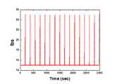
도 5는 실제 매질을 통과할때의 Torque의 변화값 실시간 측정 그래프이다.
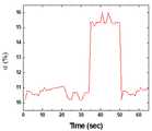
도 6은 임계값 설정하여 매질을 통과한 후 나왔을 때의 온/오프 결과를 나타낸 그래프이다.
도 7은 공회전 문제에 대한 모터 테스트 사진이다.
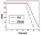
도 8은 매질이 있는 상태와 없는 상태에서의 관성에 의한 모터의 rpm 차이를 나타낸 그래프이다.
도 9는 리드스위치와 전자석을 이용한 전자기장센서(210) 테스트 결과를 나타낸 그래프이다.1 is a view showing a schematic diagram of a drill for spine equipped with the present inventors screw escape automatic detection sensor.
Figure 2 is a schematic diagram of the screw inserted into the pedicle using the present invention.
Figure 3 is a schematic diagram showing the principle of the magnetic field formed on the drill tip of the present invention.
4 is a feedback control diagram of the spinal drill of the present invention.
5 is a real-time measurement graph of the change in torque when passing through a real medium.
6 is a graph showing on / off results when exiting after passing through a medium by setting a threshold value.
7 is a motor test picture for the idle problem.
Figure 8 is a graph showing the rpm difference of the motor by the inertia in the state with and without the medium.
9 is a graph showing a test result of the electromagnetic sensor 210 using the reed switch and the electromagnet.
본 발명은 척추에 나사못(300)에 고정할 때 발생하는 나사못(300)의 높은 이탈율을 방지하기 위해, 상기 나사못(300)의 탈출을 자동으로 감지할 수 있는 센서(210)가 구비된 나사못 탈출 자동감지 센서가 구비된 척추용 드릴에 관한 것이다.The present invention in order to prevent a high escape rate of the
이상과 같은 본 발명에 대한 해결하려는 과제, 과제의 해결 수단, 발명의 효과를 포함한 구체적인 사항들은 다음에 기재할 일실시예 및 도면들에 포함되어 있다. 본 발명의 이점 및 특징, 그리고 그것들을 달성하는 방법은 첨부되는 도면과 함께 상세하게 후술되어 있는 일실시예를 참조하면 명확해질 것이다.Specific matters including the problem to be solved, the solution to the problem, and the effects of the present invention as described above are included in the embodiments and drawings to be described below. Advantages and features of the present invention, and methods for achieving them will be apparent with reference to the embodiments described below in detail in conjunction with the accompanying drawings.
하기에서는 본 발명인 나사못 탈출 자동감지 센서가 구비된 척추용 드릴을 도면을 이용하여 상세하게 설명한다.Hereinafter will be described in detail with reference to the drill for the spine equipped with the present inventors screw escape sensor.
도 1은 본 발명인 나사못 탈출 자동감지 센서가 구비된 척추용 드릴의 개요도를 나타낸 그림이다. 본 발명은 크게 드릴(100), 드릴팁(200), 나사못(300) 및 호환용프로그램(400)으로 구성된다.1 is a view showing a schematic diagram of a drill for spine equipped with the present inventors screw escape automatic detection sensor. The present invention is largely composed of a
먼저, 상기 드릴(100)은 단부에 상기 드릴팁(200)이 고정될 수 있는 연결부가 포함되어 있고, 상기 드릴팁(200)이 회전 가능하도록 구성된다.First, the
상기 드릴팁(200)의 회전력은 상기 드릴(100) 몸체부에 구비된 트리거(110)에 의해 조정되는 것이 바람직하다. 사용자에 의해 상기 트리거(110)가 강하게 당겨진 경우 상기 드릴팁(200)의 회전력이 증가하고, 상기 트리거(110)가 약하게 당겨진 경우 상기 드릴팁(200)의 회전력이 감소하도록 마련된다.Rotation force of the
다음으로, 상기 드릴팁(200)은 일단부가 상기 드릴(100)과 결합되고, 타단부가 상기 나사못(300)과 결합되도록 마련된다. 상기 기술한 바와 같이, 상기 드릴팁(200)은 상기 트리거(110)에 의해 회전력이 조절된다.Next, the
도 2에 나타난 바와 같이, 상기 드릴팁(200)은 센서(210)가 구비되는 것이 바람직하다. 상기 센서(210)는 척추경의 다른 매질을 통과하는 순간 부하가 감소하여 토크는 감소하고, 회전속도는 증가하게 되며 그 때의 토크 값 또는 회전속도 값을 측위한다. 보다 구체적으로, 상기 센서(210)가 상기 토크 값 또는 회전 속도의 차이를 감지할 때 알람이 울려 상기 나사못(300)의 위치가 정확한지를 판단할 수 있도록 한다. 또한, 상기 센서(210)는 상기 토크 값 또는 회전 속도의 차이를 감지하고, 수술 도중 상기 나사못(300)이 설정된 범위의 위치를 벗어난 경우 상기 드릴(100)의 전원을 오프(off)한다.As shown in Figure 2, the
또한, 상기 드릴팁(200)에 구비된 센서(210)는 상기 드릴팁(200)(tip)에 형성된 전기장을 통해 감지한다. 보다 구체적으로, 상기 전기장 형성은 상기 드릴팁(200)의 내부가 음극이고 외부가 양극인 것이 바람직하다. 일실시예로, 상기 나사못(300)이 잘못된 방향으로 삽입되어 골피질을 건들게 되면 상기 골피질은 전도도가 낮기 때문에 전자기장의 주파수가 낮아지게 되어 상기 드릴팁(200)에 형성된 전기장에 의해 상기 센서(210)가 이를 감지하게 된다.In addition, the sensor 210 provided in the
또한, 상기 드릴팁(200)에 구비된 센서(210)는, 상기 드릴팁(200)에 형성된 양극성(bipolar)을 통해 감지한다. 도 3에 나타난 바와 같이, 상기 드릴팁(200)에 형성된 전기장과 양극성 방식을 하나로 합하여 상기 드릴팁(200)의 내부가 음극이고 외부가 양극의 전류차를 발생시킨 뒤, 상기 드릴팁(200) 센서(210)가 전류차의 변화를 감지하여 주파수 신호를 받도록 설계되는 것이 바람직하다.In addition, the sensor 210 provided in the
다음으로, 상기 호환용프로그램(400)은 스마트 기기 또는 컴퓨터에 설치될 수 있는 것으로, 상기 호환용프로그램(400)은 상기 드릴팁(200)에 마련될 수 있는 카메라에 의해 촬영된 이미지를 실시간으로 확인할 수 있으며 제어부를 마련하여 상기 드릴팁(200)에 구비된 센서(210)가 다른 매질을 감지할 때 촬영된 이미지를 나타낼 수 있다.Next, the
일실시예로, 도 2의 개략도와 도 4에 나타난 피드백 흐름도를 참조하여 상기 나사못(300)이 척추경의 매질1(M1) 내지 매질4를 통과하여 적절한 위치에 삽입되는 과정을 설명하고자 한다.As an example, referring to the schematic diagram of FIG. 2 and the feedback flow chart shown in FIG. 4, the
먼저, 제1단계(S10)는 본 발명인 드릴(100)에 상기 나사못(300)이 장착된 드릴팁(200)이 구비된 후 상기 척추경의 매질1(M1)을 통과한다.First, the first step (S10) passes through the medium 1 (M1) of the pedicle after the
다음으로, 제2단계(S20)는 상기 센서(210)에 의해 토크 값 또는 회전속도를 감지한다.Next, the second step (S20) detects the torque value or the rotation speed by the sensor 210.
다음으로, 제3단계(S30)는 상기 센서(210)에 의해 감지된 토크 값 또는 회전속도의 변화가 사용자에 의해 설정된 1차 임계값의 범위에 해당하는지 여부를 확인한다. 상기 제3단계(S30)에서 상기 센서(210)가 감지한 토크 값 또는 회전속도의 변화가 상기 사용자가 설정한 1차 임계값의 범위에 해당하면 하기 제4단계(S40)을 실시한다.Next, the third step (S30) checks whether the change in the torque value or the rotational speed detected by the sensor 210 falls within the range of the first threshold set by the user. If the change in the torque value or the rotational speed detected by the sensor 210 in the third step (S30) falls within the range of the first threshold set by the user, the fourth step (S40) is performed.
만약, 상기 제3단계(S30)에서 상기 센서(210)가 감지한 토크 값 또는 회전속도의 변화가 상기 사용자가 설정한 1차 임계값의 범위에 미달하거나 초과하는 경우 제3-1단계(S31)를 실시한다. 보다 구체적으로, 상기 제3단계(S30)에서 상기 1차 임계값의 범위에 미달하거나 초과하는 경우, 상기 제3-1단계(S31)에서 사용자에 의해 설정된 허용 범위 값인지 판단한다. 만약, 상기 제3-1단계(S31)에서 허용 범위 값에 있으면 제3-2단계(S32)에서 사용자에게 알람을 통해 경보를 하고, 제3-3단계(S33)에서 사용자에 의해 상기 알람이 오프되면 하기 제4단계(S40)을 실시한다. 그러나 상기 제3-1단계(S31)에서 허용 범위 값을 벗어나게 되면 본 발명인 나사못(300) 탈출 자동감지 센서(210)가 구비된 척추용 드릴(100)은 전원이 오프(off)된다. 또한, 상기 제3-3단계(S33)에서 사용자에 의한 알람이 오프(off)되지 않으면 본 발명인 나사못(300) 탈출 자동감지 센서(210)가 구비된 척추용 드릴(100)은 전원이 오프(off)된다.If the change in the torque value or rotation speed detected by the sensor 210 in the third step S30 is less than or exceeds the range of the first threshold set by the user, step 3-1 (S31). ). More specifically, in the third step (S30), if it is less than or exceeds the range of the first threshold value, it is determined whether or not the allowable range value set by the user in the step 3-1 (S31). If the value is within the allowable range in step 3-1 (S31), the alarm is alerted to the user in step 3-2 (S32), and the alarm is set by the user in step 3-3 (S33). If off, the fourth step S40 is performed. However, when out of the allowable range value in the third step (S31), the
다음으로, 상기 제4단계(S40)는 상기 척추경의 매질2(M2)을 통과한 후, 제5단계(S50)에서 상기 매질1(M1)에서 매질2(M2)를 통과할 때의 토크 값 또는 회전속도를 감지한다.Next, after the fourth step (S40) passes through the medium 2 (M2) of the pedicle, the torque value when passing through the medium 2 (M2) from the medium 1 (M1) in the fifth step (S50). Or detect the rotation speed.
다음으로, 제6단계(S60)는 상기 제5단계(S50)에서 감지된 토크 값 또는 회전속도의 차이가 사용자에 의해 설정된 2차 임계값 내의 범위인지 확인한다. 보다 구체적으로, 상기 사용자가 설정한 2차 임계값의 범위에 미달하거나 초과하는 경우 제6-1단계(S61)를 실시한다. 상기 제6단계(S60)에서 상기 2차 임계값의 범위에 미달하거나 초과하는 경우, 상기 제6-1단계(S61)에서 사용자에 의해 설정된 허용 범위 값인지 판단한다. 만약, 상기 제6-1단계(S61)에서 허용 범위 값에 있으면 알람을 통해 경보를 하고, 제6-2단계(S62)에서 사용자에 의해 상기 알람이 오프되면 하기 제7단계(S70)을 실시한다. 그러나 상기 제6-1단계(S61)에서 허용 범위 값을 벗어나게 되면 본 발명인 나사못(300) 탈출 자동감지 센서(210)가 구비된 척추용 드릴(100)은 전원이 오프(off)된다. 또한, 상기 제6-3단계(S63)에서 사용자에 의한 알람이 오프(off)되지 않으면 본 발명인 나사못(300) 탈출 자동감지 센서(210)가 구비된 척추용 드릴(100)은 전원이 오프(off)된다.Next, the sixth step S60 checks whether the difference in the torque value or the rotational speed detected in the fifth step S50 is within a secondary threshold set by the user. More specifically, if the user falls below or exceeds the range of the secondary threshold set by the user, step 6-1 (S61) is performed. In the sixth step (S60), if it is less than or exceeds the range of the second threshold value, it is determined whether or not the allowable range value set by the user in the step 6-1 (S61). If the value is within the allowable range in step 6-1 (S61), an alarm is issued through an alarm, and if the alarm is turned off by the user in step 6-2 (S62), the following step 7 (S70) is performed. do. However, if out of the allowable range value in the 6-1 step (S61), the
다음으로, 상기 제7단계(S70)는 상기 척추경의 매질3(M3)을 통과한 후, 제8단계(S80)에서 상기 매질2(M2)에서 매질3(M3)을 통과할 때의 토크 값 또는 회전속도를 감지한다.Next, the seventh step (S70) after passing through the medium 3 (M3) of the pedicle, the torque value when passing through the medium 3 (M3) in the medium 2 (M2) in the eighth step (S80). Or detect the rotation speed.
다음으로, 제9단계(S90)는 상기 제8단계(S80)에서 감지된 토크 값 또는 회전속도의 차이가 사용자에 의해 설정된 3차 임계값 내의 범위인지 확인한다. 보다 구체적으로, 상기 사용자가 설정한 3차 임계값의 범위에 미달하거나 초과하는 경우 제9-1단계(S91)를 실시한다. 상기 제9단계(S90)에서 상기 3차 임계값의 범위에 미달하거나 초과하는 경우, 상기 제9-1단계(S91)에서 사용자에 의해 설정된 허용 범위 값인지 판단한다. 만약, 상기 제9-1단계(S91)에서 허용 범위 값에 있으면 알람을 통해 경보를 하고, 제9-2단계(S92)에서 사용자에 의해 상기 알람이 오프되면 하기 제10단계(S100)을 실시한다. 그러나 상기 제9-1단계(S91)에서 허용 범위 값을 벗어나게 되면 본 발명인 나사못(300) 탈출 자동감지 센서(210)가 구비된 척추용 드릴(100)은 전원이 오프(off)된다. 또한, 상기 제9-3단계(S93)에서 사용자에 의한 알람이 오프(off)되지 않으면 본 발명인 나사못(300) 탈출 자동감지 센서(210)가 구비된 척추용 드릴(100)은 전원이 오프(off)된다.Next, the ninth step S90 checks whether the difference in the torque value or the rotation speed detected in the eighth step S80 is within a third threshold set by the user. More specifically, if the user falls below or exceeds the third threshold set by the user, step 9-1 (S91) is performed. In the ninth step (S90), if the range falls below or exceeds the third threshold value, it is determined whether the allowable range value set by the user is set in the ninth step (S91). If the value is within the allowable range in step 9-1 (S91), an alarm is issued through an alarm, and if the alarm is turned off by the user in step 9-2 (S92), the following tenth step (S100) is performed. do. However, when out of the allowable range in the ninth step (S91), the
마지막으로, 상기 제10단계(S100)는 상기 매질4(M4)를 통과한 뒤 사용자에 의해 상기 드릴팁(200)이 제거되고 상기 척추경에 상기 나사못(300)을 삽입하는 수술이 완성된다.Finally, the tenth step (S100) is passed through the medium 4 (M4) and the
하기는 본 발명인 나사못 탈출 자동감지 센서가 구비된 척추용 드릴을 이용하여 테스트를 실시한 결과이다.The following is a result of the test using a drill for spine equipped with the present inventors screw escape automatic detection sensor.
ㄱ. 서로 다른 매질에서의 테스트G. Test in different media
본 실험은 한계점 적용이 가능하다고 판단된 목재 재료를 드릴링하여 실험을 진행하였다. 각 매질에서의 실험을 통해 본 발명인 나사못 탈출 자동감지 센서가 구비된 척추용 드릴의 온/오프 기능을 확인하고, 실제 임상 실험적용을 추후 진행하면 수술시 사용 가능할 것으로 판단하였다.The experiment was carried out by drilling wood materials that were considered to be applicable to the limit. Experiments in each medium to check the on / off function of the spinal drill equipped with the present inventors automatic screw escape sensor, it was determined that the future clinical trials can be used during surgery.
도 5는 실제 매질을 통과할 때의 토크의 실시간 변화값을 측정한 것으로 각 매질에서 토크의 변화가 있음을 확인할 수 있다. 또한, 도 6은 임계점을 설정한 후 매질을 통과하였을 때의 온/오프 결과값을 나타낸 것으로 센서(210)에 의해 다른 매질을 확인하여 드릴이 오프되었을 때에도 약 4초간 공회전이 되는 것을 알 수 있다.5 is a measurement of the real-time change of the torque when passing through the actual medium, it can be seen that there is a change in torque in each medium. In addition, Figure 6 shows the on / off result when passing through the medium after setting the critical point, it can be seen that the idle time for about 4 seconds even when the drill is turned off by checking the other medium by the sensor 210. .
본 테스트를 통해 서로 다른 매질을 통과할 때 토크 값의 변화가 실시간으로 있음을 확인하였고, 임계값을 적용하였을 때 상기 센서(210)에 의해 드릴의 작동이 자동적으로 멈춤을 확인하였다. 다만, 상기 드릴이 오프된 후에도 모터의 관성에 의해 공회전의 문제점이 발생되었고, 상기 공회전 문제을 해결하기 위해 하기와 같은 테스트를 진행하였다.This test confirms that the torque value changes in real time when passing through different media, and when the threshold is applied, it is confirmed that the operation of the drill is automatically stopped by the sensor 210. However, even after the drill was turned off, the problem of idling occurred due to the inertia of the motor, and the following test was performed to solve the idling problem.
ㄴ. 공회전 문제에 대한 테스트N. Test for idle problem
서로 다른 매질에서의 테스트에서 확인한 바와 같이 모터의 관성에 의한 공회전 문제를 해결하기 위해 온/오프 방식에서의 공회전 문제점을 해결하기 위한 모터의 관성에 대한 테스트를 진행하였다.In order to solve the idling problem caused by the inertia of the motor, as tested in different media, the inertia of the motor was solved to solve the idling problem in the on / off method.
도 7에 나타난 바와 같이 공회전 문제에 대한 모터 테스트를 위해 사진에 나타난 장치를 설치하고, 실험을 진행하였다. 그 결과로 도 8에 나타난 그래프와 같이 매질이 있는 상태와 없는 상태에서의 관성에 의한 RPM 차이를 확인할 수 있었다.As shown in FIG. 7, the apparatus shown in the photograph was installed for the motor test for the idling problem, and the experiment was performed. As a result, as shown in the graph shown in Figure 8 it was confirmed the difference in RPM due to the inertia in the state with and without the medium.
보다 구체적으로, 매질이 있는 상태와 없는 상태에서의 관성에 의한 모터가 공회전 하는 시간차이가 약 5초 정도 나타나는 것을 확인하였고 일반적인 토크센서(210)만으로 한계가 있을 것으로 판단하였다. 따라서 본 발명에 의한 나사못 탈출 자동감지 센서가 구비된 척추용 드릴의 경우 이러한 공회전에 의한 의료사고가 발생할 수 있으므로 상기 문제점을 보완할 수 있는 추가 기술이 필요할 것으로 판단되었다.More specifically, it was confirmed that the time difference between the motor idling due to inertia in the state with and without the medium appeared about 5 seconds and it was determined that there was a limit only with the general torque sensor 210. Therefore, in the case of a spinal drill equipped with a screw escape auto-sensing sensor according to the present invention, medical accidents may occur due to such idling.
ㄷ. 공회전 문제를 보정하기 위한 자기장센서(210) 테스트C. Magnetic Field Sensor (210) Test to Correct Idle Problems
이론적으로 cortical bone, cnacellous bone, blood 등 척추뼈에서의 3가지는 각각 다른 전기장을 갖는다. 따라서 전기장센서(210)를 이용하여 위와 같은 3가지를 구분하여 감지할 수 있다.Theoretically, each of the three vertebrae, the cortical bone, the cnacellous bone, and the blood, has different electric fields. Therefore, by using the electric field sensor 210 can be detected by distinguishing the above three types.
도 9에 나타난 바와 같이, 리드스위치와 전자석을 이용하여 전자기장센서(210)를 테스트하였을 때 전자기장 센서(210)의 거리에 따라 자기장값의 변화를 확인할 수 있었다. 이론적으로 cortical bone은 약 25%, cancellous bone은 약 50%, blood는 90%의 자기장 값을 가진다. 따라서 바이폴라(bipolar) 센서(210)를 이용하여 작은 팁 형식으로 제작 가능할 것으로 예상하였다. 결론적으로, 공회전 문제를 전자기장센서(210)와 결합하여 안정적이고 편리한 자동화 척추못 나사 드릴을 개발할 수 있었다.As shown in FIG. 9, when the electromagnetic sensor 210 was tested using the reed switch and the electromagnet, the change in the magnetic field value was confirmed according to the distance of the electromagnetic sensor 210. Theoretically, magnetic field values of about 25% for cortical bones, about 50% for cancellous bones, and 90% for blood. Therefore, it is expected that the bipolar sensor 210 may be manufactured in a small tip form. In conclusion, by combining the idling problem with the electromagnetic field sensor 210, it was possible to develop a stable and convenient automated spinal nail screw drill.
상기 과제의 해결 수단에 의해, 본 발명은 고가 장비인 영상 장치를 이용하지 않고 척추에 나사못 삽입의 정확성을 높일 수 있는 드릴을 제조할 수 있다.By the means for solving the above problems, the present invention can manufacture a drill that can increase the accuracy of screw insertion into the spine without using an imaging device that is expensive equipment.
또한, 본 발명은 미세한 나사못 이탈을 감지할 수 있는 기능이 구비된 척추 나사못 드릴을 제조할 수 있다.In addition, the present invention can manufacture a spinal screw drill with a function that can detect fine screw departure.
또한, 본 발명은 척추경에 나사못 결합이 용이하고 상용화가 가능한 척추 나사못 드릴을 제조할 수 있다.In addition, the present invention can manufacture a spinal screw drill that is easy to commercialize screw coupling to the pedicle.
이와 같이, 상술한 본 발명의 기술적 구성은 본 발명이 속하는 기술분야의 당업자가 본 발명의 그 기술적 사상이나 필수적 특징을 변경하지 않고서 다른 구체적인 형태로 실시될 수 있다는 것을 이해할 수 있을 것이다.As such, the technical configuration of the present invention described above can be understood by those skilled in the art that the present invention can be implemented in other specific forms without changing the technical spirit or essential features of the present invention.
그러므로 이상에서 기술한 실시예들은 모든 면에서 예시적인 것이며 한정적인 것이 아닌 것으로서 이해되어야 하고, 본 발명의 범위는 상기 상세한 설명보다는 후술하는 특허청구범위에 의하여 나타나며, 특허청구범위의 의미 및 범위 그리고 그 등가 개념으로부터 도출되는 모든 변경 또는 변형된 형태가 본 발명의 범위에 포함되는 것으로 해석되어야 한다.Therefore, the above-described embodiments are to be understood as illustrative and not restrictive in all respects, and the scope of the present invention is indicated by the following claims rather than the detailed description, and the meaning and scope of the claims and their All changes or modifications derived from an equivalent concept should be construed as being included in the scope of the present invention.
100. 드릴
110. 트리거
200. 드릴팁
210. 센서
300. 나사못
400. 호환용프로그램
S10. 드릴(100)에 상기 나사못(300)이 장착된 드릴팁(200)이 구비된 후 상기 척추경의 매질1(M1)을 통과하는 제1단계;
S20. 상기 드릴팁(200)에 구비된 센서(210)에 의해 토크 값 또는 회전속도를 감지하는 제2단계;
S30. 상기 센서(210)에 의해 감지된 토크 값 또는 회전속도의 변화가 사용자에 의해 설정된 1차 임계값의 범위에 해당하는지 여부를 확인하는 제3단계;
S31. 상기 제3단계(S30)에서 상기 센서(210)가 감지한 토크 값 또는 회전속도의 변화가 상기 사용자가 설정한 1차 임계값의 범위에 미달하거나 초과하는 경우 실시되는 제3-1단계;
S32. 상기 제3-1단계(S31)에서 허용 범위 값에 있으면 사용자에게 알람을 통해 경보를 하는 제3-2단계;
S33. 사용자에 의해 알람의 오프(off) 여부를 확인하는 제3-3단계;
S40. 상기 드릴팁(200)이 상기 척추경의 매질2(M2)을 통과하는 제4단계;
S50. 상기 매질1(M1)에서 매질2(M2)를 통과할 때의 토크 값 또는 회전속도를 감지하는 제5단계;
S60. 상기 센서(210)에 의해 감지된 토크 값 또는 회전속도의 변화가 사용자에 의해 설정된 2차 임계값의 범위에 해당하는지 여부를 확인하는 제6단계;
S61. 상기 제6단계(S60)에서 상기 센서(210)가 감지한 토크 값 또는 회전속도의 변화가 상기 사용자가 설정한 2차 임계값의 범위에 미달하거나 초과하는 경우 실시되는 제6-1단계;
S62. 상기 제6-1단계(S61)에서 허용 범위 값에 있으면 사용자에게 알람을 통해 경보를 하는 제6-2단계;
S63. 사용자에 의해 알람의 오프(off) 여부를 확인하는 제6-3단계;
S70. 상기 드릴팁(200)이 상기 척추경의 매질3(M3)을 통과하는 제7단계;
S80. 상기 매질1(M1)에서 매질2(M2)를 통과할 때의 토크 값 또는 회전속도를 감지하는 제8단계;
S90. 상기 센서(210)에 의해 감지된 토크 값 또는 회전속도의 변화가 사용자에 의해 설정된 3차 임계값의 범위에 해당하는지 여부를 확인하는 제9단계;
S91. 상기 제9단계(S60)에서 상기 센서(210)가 감지한 토크 값 또는 회전속도의 변화가 상기 사용자가 설정한 3차 임계값의 범위에 미달하거나 초과하는 경우 실시되는 제9-1단계;
S92. 상기 제9-1단계(S91)에서 허용 범위 값에 있으면 사용자에게 알람을 통해 경보를 하는 제9-2단계;
S93. 사용자에 의해 알람의 오프(off) 여부를 확인하는 제9-3단계;
S100. 매질4(M4)를 통과한 뒤 사용자에 의해 상기 드릴팁(200)이 제거되고 상기 척추경에 상기 나사못(300)을 삽입하는 수술이 완성되는 제10단계;100. Drill
110. Trigger
200. Drill Tip
210. Sensor
300. Screws
400. Compatible Applications
S10. A first step of passing through the medium 1 (M1) of the pedicle after the
S20. A second step of detecting a torque value or a rotation speed by a sensor 210 provided in the
S30. A third step of confirming whether a change in torque value or rotation speed sensed by the sensor 210 falls within a range of a first threshold set by a user;
S31. A third step performed when the change of the torque value or the rotational speed detected by the sensor 210 in the third step (S30) is less than or exceeds the range of the first threshold set by the user;
S32. Step 3-2 of alerting the user through an alarm when the value is within the allowable range in step 3-1 (S31);
S33. Step 3-3 of checking whether the alarm is turned off by the user;
S40. A fourth step in which the
S50. A fifth step of detecting a torque value or a rotation speed when the medium 1 (M1) passes through the medium 2 (M2);
S60. A sixth step of checking whether a change in torque value or rotation speed detected by the sensor 210 falls within a range of a second threshold set by a user;
S61. Step 6-1 performed when the change in the torque value or the rotational speed detected by the sensor 210 in the sixth step (S60) is less than or exceeds the range of the secondary threshold set by the user;
S62. Step 6-2 to alert the user through an alarm when the value is within the allowable range in step 6-1 (S61);
S63. Step 6-3 checking whether the alarm is turned off by the user;
S70. A seventh step of passing the
S80. An eighth step of detecting a torque value or a rotation speed when the medium 1 (M1) passes through the medium 2 (M2);
S90. A ninth step of checking whether a change in torque value or rotation speed sensed by the sensor 210 falls within a range of a third threshold set by a user;
S91. A step 9-1 performed when the change in the torque value or the rotational speed detected by the sensor 210 in the ninth step S60 is less than or exceeds the range of the third threshold value set by the user;
S92. A step 9-2 of alerting the user through an alarm when the value is within the allowable range in the step 9-1 (S91);
S93. Step 9-3 checking whether the alarm is turned off by the user;
S100. A tenth step of removing the
Claims (5)
Translated fromKorean상기 몸체부에 구비되어 상기 드릴팁(200)의 회전력을 조절하는 트리거(110);
상기 드릴팁의 타단부에 결합되어 상기 드릴팁(200)에 일단부가 삽입되고, 타단부가 척추경으로 삽입되는 나사못(300);
상기 드릴팁(200) 일측에 마련되어 상기 나사못(300)이 척추경의 다른 매질을 통과할 때 토크 값 또는 회전 속도의 차이를 감지하는 센서(210);로 구성하되,
상기 센서(210)는 내부가 음극이고 외부가 양극인 전기장을 형성하여 상기 나사못(300)이 척추경의 다른 매질을 통과할 때 토크 값 또는 회전 속도의 차이를 감지하고,
상기 센서(210)는 상기 토크 값의 차이를 감지할 때 알람이 울리며,
상기 센서(210)는 상기 토크 값의 차이를 감지할 때 드릴의 전원을 오프(off)하는 것을 특징으로 하는 나사못 탈출 자동감지 센서가 구비된 척추용 드릴.
A drill tip 200 having one end coupled to the body portion and rotating;
A trigger (110) provided on the body to adjust a rotational force of the drill tip (200);
A screw 300 coupled to the other end of the drill tip and having one end inserted into the drill tip 200 and the other end inserted into the pedicle;
Is provided on one side of the drill tip 200, the sensor 300 for sensing the difference in torque value or rotational speed when the screw 300 passes through the other medium of the pedicle;
The sensor 210 forms an electric field inside the cathode and outside the anode to detect a difference in torque value or rotational speed when the screw 300 passes through another medium of the pedicle,
When the sensor 210 detects the difference in the torque value, an alarm sounds,
The sensor 210 is provided with a screw escape auto-sensing sensor, characterized in that the power off of the drill (off) when detecting the difference in the torque value.
상기 드릴은,
스마트 기기 또는 컴퓨터와 호환되는 것을 특징으로 하는 나사못 탈출 자동감지 센서가 구비된 척추용 드릴.The method of claim 1,
The drill,
Spinal drill with a screw escape auto-sensing sensor characterized in that it is compatible with smart devices or computers.
Priority Applications (1)
| Application Number | Priority Date | Filing Date | Title |
|---|---|---|---|
| KR1020170175440AKR102007430B1 (en) | 2017-12-19 | 2017-12-19 | Drill device for veltebra with auto sensor for escaping of tip |
Applications Claiming Priority (1)
| Application Number | Priority Date | Filing Date | Title |
|---|---|---|---|
| KR1020170175440AKR102007430B1 (en) | 2017-12-19 | 2017-12-19 | Drill device for veltebra with auto sensor for escaping of tip |
Publications (2)
| Publication Number | Publication Date |
|---|---|
| KR20190074069A KR20190074069A (en) | 2019-06-27 |
| KR102007430B1true KR102007430B1 (en) | 2019-10-01 |
Family
ID=67057314
Family Applications (1)
| Application Number | Title | Priority Date | Filing Date |
|---|---|---|---|
| KR1020170175440AExpired - Fee RelatedKR102007430B1 (en) | 2017-12-19 | 2017-12-19 | Drill device for veltebra with auto sensor for escaping of tip |
Country Status (1)
| Country | Link |
|---|---|
| KR (1) | KR102007430B1 (en) |
Cited By (1)
| Publication number | Priority date | Publication date | Assignee | Title |
|---|---|---|---|---|
| US11806095B2 (en) | 2020-06-17 | 2023-11-07 | Mazor Robotics Ltd. | Torque sensor with decision support and related systems and methods |
Citations (5)
| Publication number | Priority date | Publication date | Assignee | Title |
|---|---|---|---|---|
| KR100695471B1 (en) | 2005-10-07 | 2007-03-16 | 한양대학교 산학협력단 | Multiple degree of freedom robot for positioning surgical instruments |
| KR100930369B1 (en) | 2009-05-04 | 2009-12-08 | 김영우 | Electric screw driver for spine |
| KR101020247B1 (en)* | 2010-10-28 | 2011-03-07 | 주식회사 디오메디칼 | Screwdriver for pedicle screw |
| US20150216541A1 (en) | 2014-02-03 | 2015-08-06 | Arthrex, Inc. | Pointing device and drilling tool |
| US20160120553A1 (en) | 2013-07-09 | 2016-05-05 | Jenny Xie | Surgical drill having a brake that, upon the drill bit penetrating through bone, prevents further insertion of the drill |
Family Cites Families (2)
| Publication number | Priority date | Publication date | Assignee | Title |
|---|---|---|---|---|
| EP2241270B1 (en)* | 2005-06-28 | 2012-10-10 | Stryker Corporation | Control assembly for a motorized surgical tool that contains a sensor that monitors the state of the motor rotor |
| KR101575948B1 (en)* | 2014-03-26 | 2015-12-10 | 경북대학교 산학협력단 | Medical current test apparatus |
- 2017
- 2017-12-19KRKR1020170175440Apatent/KR102007430B1/ennot_activeExpired - Fee Related
Patent Citations (5)
| Publication number | Priority date | Publication date | Assignee | Title |
|---|---|---|---|---|
| KR100695471B1 (en) | 2005-10-07 | 2007-03-16 | 한양대학교 산학협력단 | Multiple degree of freedom robot for positioning surgical instruments |
| KR100930369B1 (en) | 2009-05-04 | 2009-12-08 | 김영우 | Electric screw driver for spine |
| KR101020247B1 (en)* | 2010-10-28 | 2011-03-07 | 주식회사 디오메디칼 | Screwdriver for pedicle screw |
| US20160120553A1 (en) | 2013-07-09 | 2016-05-05 | Jenny Xie | Surgical drill having a brake that, upon the drill bit penetrating through bone, prevents further insertion of the drill |
| US20150216541A1 (en) | 2014-02-03 | 2015-08-06 | Arthrex, Inc. | Pointing device and drilling tool |
Cited By (1)
| Publication number | Priority date | Publication date | Assignee | Title |
|---|---|---|---|---|
| US11806095B2 (en) | 2020-06-17 | 2023-11-07 | Mazor Robotics Ltd. | Torque sensor with decision support and related systems and methods |
Also Published As
| Publication number | Publication date |
|---|---|
| KR20190074069A (en) | 2019-06-27 |
Similar Documents
| Publication | Publication Date | Title |
|---|---|---|
| US10076385B2 (en) | Method and apparatus for alerting a user to sensed lateral forces upon a guide-sleeve in a robot surgical system | |
| US11471220B2 (en) | Image-guided minimal-step placement of screw into bone | |
| US11344372B2 (en) | Robotic surgical system | |
| CN111542266B (en) | Medical system | |
| EP3197382B1 (en) | Tracking marker support structure and surface registration methods employing the same for performing navigated surgical procedures | |
| CN107454834B (en) | System and method for placing a medical device in a bone | |
| BR112013021042B1 (en) | MANUAL TOOL | |
| US20090149862A1 (en) | Guide pin for pedicle screw placement and method for use of such guide pin in spinal fusion surgeries | |
| US20230095197A1 (en) | Universal adapter for handheld surgical systems | |
| US20200192323A1 (en) | Electrically controllable rotary pressure device and method for controlling the same | |
| US20220104833A1 (en) | Feature-based surgical tool identification | |
| KR102007430B1 (en) | Drill device for veltebra with auto sensor for escaping of tip | |
| Han et al. | Pedicle screw placement in the thoracic spine: a comparison study of computer-assisted navigation and conventional techniques | |
| US20220233250A1 (en) | Surgical system with navigation | |
| US20240237994A1 (en) | Universal adapter for handheld surgical systems | |
| WO2016043676A1 (en) | A pedicle screw with warning system | |
| HK40055430A (en) | System and method for medical device placement in bone | |
| HK40055431A (en) | System and method for medical device placement in bone | |
| CN105361857A (en) | Harpoon-shaped lacrimal duct detection and recanalization method |
Legal Events
| Date | Code | Title | Description |
|---|---|---|---|
| A201 | Request for examination | ||
| PA0109 | Patent application | St.27 status event code:A-0-1-A10-A12-nap-PA0109 | |
| PA0201 | Request for examination | St.27 status event code:A-1-2-D10-D11-exm-PA0201 | |
| E902 | Notification of reason for refusal | ||
| PE0902 | Notice of grounds for rejection | St.27 status event code:A-1-2-D10-D21-exm-PE0902 | |
| E13-X000 | Pre-grant limitation requested | St.27 status event code:A-2-3-E10-E13-lim-X000 | |
| P11-X000 | Amendment of application requested | St.27 status event code:A-2-2-P10-P11-nap-X000 | |
| P13-X000 | Application amended | St.27 status event code:A-2-2-P10-P13-nap-X000 | |
| E90F | Notification of reason for final refusal | ||
| PE0902 | Notice of grounds for rejection | St.27 status event code:A-1-2-D10-D21-exm-PE0902 | |
| E13-X000 | Pre-grant limitation requested | St.27 status event code:A-2-3-E10-E13-lim-X000 | |
| P11-X000 | Amendment of application requested | St.27 status event code:A-2-2-P10-P11-nap-X000 | |
| P13-X000 | Application amended | St.27 status event code:A-2-2-P10-P13-nap-X000 | |
| PG1501 | Laying open of application | St.27 status event code:A-1-1-Q10-Q12-nap-PG1501 | |
| E701 | Decision to grant or registration of patent right | ||
| PE0701 | Decision of registration | St.27 status event code:A-1-2-D10-D22-exm-PE0701 | |
| GRNT | Written decision to grant | ||
| PR0701 | Registration of establishment | St.27 status event code:A-2-4-F10-F11-exm-PR0701 | |
| PR1002 | Payment of registration fee | St.27 status event code:A-2-2-U10-U11-oth-PR1002 Fee payment year number:1 | |
| PG1601 | Publication of registration | St.27 status event code:A-4-4-Q10-Q13-nap-PG1601 | |
| PR1001 | Payment of annual fee | St.27 status event code:A-4-4-U10-U11-oth-PR1001 Fee payment year number:4 | |
| PR1001 | Payment of annual fee | St.27 status event code:A-4-4-U10-U11-oth-PR1001 Fee payment year number:5 | |
| PN2301 | Change of applicant | St.27 status event code:A-5-5-R10-R13-asn-PN2301 St.27 status event code:A-5-5-R10-R11-asn-PN2301 | |
| R18-X000 | Changes to party contact information recorded | St.27 status event code:A-5-5-R10-R18-oth-X000 | |
| PC1903 | Unpaid annual fee | St.27 status event code:A-4-4-U10-U13-oth-PC1903 Not in force date:20240731 Payment event data comment text:Termination Category : DEFAULT_OF_REGISTRATION_FEE | |
| PN2301 | Change of applicant | St.27 status event code:A-5-5-R10-R13-asn-PN2301 St.27 status event code:A-5-5-R10-R11-asn-PN2301 | |
| R18-X000 | Changes to party contact information recorded | St.27 status event code:A-5-5-R10-R18-oth-X000 | |
| PC1903 | Unpaid annual fee | St.27 status event code:N-4-6-H10-H13-oth-PC1903 Ip right cessation event data comment text:Termination Category : DEFAULT_OF_REGISTRATION_FEE Not in force date:20240731 |