KR102007387B1 - Tissue biopsy device with thumbwwheel and sample holder - Google Patents
Tissue biopsy device with thumbwwheel and sample holderDownload PDFInfo
- Publication number
- KR102007387B1 KR102007387B1KR1020157011921AKR20157011921AKR102007387B1KR 102007387 B1KR102007387 B1KR 102007387B1KR 1020157011921 AKR1020157011921 AKR 1020157011921AKR 20157011921 AKR20157011921 AKR 20157011921AKR 102007387 B1KR102007387 B1KR 102007387B1
- Authority
- KR
- South Korea
- Prior art keywords
- gear
- needle
- tissue sample
- thumbwheel
- sample holder
- Prior art date
- Legal status (The legal status is an assumption and is not a legal conclusion. Google has not performed a legal analysis and makes no representation as to the accuracy of the status listed.)
- Expired - Fee Related
Links
Images


Classifications
- A—HUMAN NECESSITIES
- A61—MEDICAL OR VETERINARY SCIENCE; HYGIENE
- A61B—DIAGNOSIS; SURGERY; IDENTIFICATION
- A61B10/00—Instruments for taking body samples for diagnostic purposes; Other methods or instruments for diagnosis, e.g. for vaccination diagnosis, sex determination or ovulation-period determination; Throat striking implements
- A61B10/02—Instruments for taking cell samples or for biopsy
- A61B10/0233—Pointed or sharp biopsy instruments
- A—HUMAN NECESSITIES
- A61—MEDICAL OR VETERINARY SCIENCE; HYGIENE
- A61B—DIAGNOSIS; SURGERY; IDENTIFICATION
- A61B10/00—Instruments for taking body samples for diagnostic purposes; Other methods or instruments for diagnosis, e.g. for vaccination diagnosis, sex determination or ovulation-period determination; Throat striking implements
- A61B10/0096—Casings for storing test samples
- A—HUMAN NECESSITIES
- A61—MEDICAL OR VETERINARY SCIENCE; HYGIENE
- A61B—DIAGNOSIS; SURGERY; IDENTIFICATION
- A61B10/00—Instruments for taking body samples for diagnostic purposes; Other methods or instruments for diagnosis, e.g. for vaccination diagnosis, sex determination or ovulation-period determination; Throat striking implements
- A61B10/02—Instruments for taking cell samples or for biopsy
- A61B10/0233—Pointed or sharp biopsy instruments
- A61B10/0283—Pointed or sharp biopsy instruments with vacuum aspiration, e.g. caused by retractable plunger or by connected syringe
- A—HUMAN NECESSITIES
- A61—MEDICAL OR VETERINARY SCIENCE; HYGIENE
- A61B—DIAGNOSIS; SURGERY; IDENTIFICATION
- A61B10/00—Instruments for taking body samples for diagnostic purposes; Other methods or instruments for diagnosis, e.g. for vaccination diagnosis, sex determination or ovulation-period determination; Throat striking implements
- A61B10/02—Instruments for taking cell samples or for biopsy
- A61B2010/0208—Biopsy devices with actuators, e.g. with triggered spring mechanisms
Landscapes
- Health & Medical Sciences (AREA)
- Life Sciences & Earth Sciences (AREA)
- Surgery (AREA)
- Animal Behavior & Ethology (AREA)
- Biomedical Technology (AREA)
- Heart & Thoracic Surgery (AREA)
- Medical Informatics (AREA)
- Molecular Biology (AREA)
- Pathology (AREA)
- Engineering & Computer Science (AREA)
- General Health & Medical Sciences (AREA)
- Public Health (AREA)
- Veterinary Medicine (AREA)
- Surgical Instruments (AREA)
- Sampling And Sample Adjustment (AREA)
- Investigating Or Analysing Biological Materials (AREA)
Abstract
Translated fromKorean
Description
Translated fromKorean본 출원은, 2012년 10월 8일자로 출원된 미국 특허 가출원 제 61/711,026 호 "덤휠 및 조직샘플홀더와 선택적으로 회전가능하게 연결된 조직생검장치(TISSUE BIOPSY DEVICE WITH SELECTIVELY ROTATABLY LINKED THUMBWHEEL AND TISSUE SAMPLE HOLDER)"를 우선권으로 주장하는 2013년 3월 13일자로 출원된 미국 특허 출원 제 13/800,502 호 "덤휠 및 조직샘플홀더와 선택적으로 회전가능하게 연결된 조직생검장치"를 우선권으로 주장하며, 상기의 각 특허 출원은 전체적으로 여기에서 통합된다.The present application, US Patent Provisional Application No. 61 / 711,026, filed Oct. 8, 2012 "TISSUE BIOPSY DEVICE WITH SELECTIVELY ROTATABLY LINKED THUMBWHEEL AND TISSUE SAMPLE HOLDER US Patent Application No. 13 / 800,502 filed on March 13, 2013, which claims ")" as a priority, claims "Tissue biopsy device that is selectively rotatably connected to a dumbwheel and tissue sample holder." Patent applications are incorporated herein in their entirety.
본 발명의 형태들은 일반적인 생검장치들(biopsy devices, 생체검사 장치들)과 관련되며, 더 상세하게는 생검장치의 일부분 내에서 이격되고 연속되는 방식(spaced-apart, sequenced manner)으로 다양한 조직 샘플들을 저장할 수 있는 기능을 갖는 생검장치에 관한 것이다.
Aspects of the present invention relate to general biopsy devices, and more particularly to various tissue samples in a spaced-apart, sequenced manner within a portion of the biopsy device. The present invention relates to a biopsy device having a storage function.
초음파, MRI, X레이 이미징 또는 이와 유사한 검사를 통해서 의심이 가는 조직체(tissue mass)가 환자의 가슴 또는 다른 부위에 발견됐을 때, 상기 조직체가 암세포들(cancerous cells)을 포함하고 있는지 여부를 파악하기 위하여 조직에서 하나 이상의 샘플들을 떼어내서 생검절차(biopsy procedure)를 수행할 필요가 있다. 생검은 개방(open) 또는 경피적(percutaneous) 방법을 사용하여 수행될 수 있다. 순차적인 샘플링 및/또는 테스팅을 위한 조직 샘플 획득용 의료장치들은 생검 분야에서 알려져 있다. 예를 들면, MAMMOTOME®REVOLVE™ 을 포함하여 MAMMOTOME®라는 상표명으로 현재 판매되는 생검장비는 가슴 생검 샘플들을 얻기 위해 사용되며 Devicor Medical Products 社 로부터 상업적으로 이용가능하다.Ultrasound, MRI, X-ray imaging, or similar tests to determine whether the tissue contains cancerous cells when a suspicious tissue is found in the patient's chest or other area In order to perform a biopsy procedure, one or more samples are removed from the tissue. Biopsies can be performed using open or percutaneous methods. Medical devices for obtaining tissue samples for sequential sampling and / or testing are known in the biopsy art. For example, currently available biopsy instruments under the trade name MAMMOTOME® , including MAMMOTOME® REVOLVE ™, are used to obtain chest biopsy samples and are commercially available from Devicor Medical Products.
개방생검(open biopsy)은 가슴을 크게 절개한 후, 절제생검(excisional biopsy)이라고 불리는 전체 조직을 제거하는 방식 또는 절개생검(incisional biopsy)이라고 불리는 가슴 조직의 실질 부위만 제거하는 방식으로 수행될 수 있다. 개방생검은 외과센터 또는 병원에서 외래수술(outpatient procedure)로써 실시될 것인 외과적 절차이며, 환자는 높은 비용과 높은 수준의 트라우마(trauma)를 받게 될 수 있다. 개방생검은 경피생검(percutaneous biopsy) 보다 상대적으로 감염 및 출혈 위험이 높은 상태로 실시될 것이며, 개방생검에 의해 흉터가 남게될 것이고, 차후에 유방조영상들(mammograms)을 판독하는 것을 어렵게 할 것이다. 추가적으로, 환자의 미적인 사항들을 고려하면 흉터의 잠재적 위험이 있기 때문에 개방생검은 매력이 감소된다. 몇몇 생검의 경우에서 의심스러운 조직들이 암이 아닌 것으로 밝혀진 상황이라면, 개방생검 절차의 상기 잠재적인 단점들은 몇몇 케이스에서 적합하지 않는 방식으로 간주될 수 있을 것이다.Open biopsy can be performed by making a large incision in the chest and then removing the entire tissue called excisional biopsy or removing only the parenchymal region of the chest tissue called incisional biopsy. have. Open biopsy is a surgical procedure that will be performed as an outpatient procedure in a surgical center or hospital, and patients may be subject to high cost and high levels of trauma. Open biopsies will be performed with a relatively higher risk of infection and bleeding than percutaneous biopsy, will leave scars by open biopsies and will make it difficult to read mammograms in the future. In addition, the open biopsy reduces the attractiveness, given the aesthetic concerns of the patient and the potential risk of scarring. If in some biopsy cases it is found that suspicious tissues are not cancerous, the potential drawbacks of the open biopsy procedure may be considered in an unsuitable manner in some cases.
경피생검은 개방생검 보다 절개가 더 적게 이뤄진다. 경피생검은 미세니들흡인(fine needle aspiration: FNA), 코어니들생검(core needle biopsy) 또는 다른 방식 등을 통해 수행될 것이다. FNA 에서, 매우 가느다란 니들은 의심이 가는 조직체에서 분비액과 세포들을 빼내도록 사용될 것이다. 이러한 방법은 약간의 통증만 유발할 것이며 따라서, FNA 자체보다 국부마취(local anesthetic)를 시술하는 것이 더 고통스러울 수도 있으므로 국부마취가 항상 요구되지는 않는다. 그러나, 몇몇 FNA 절차에는 단지 작은 수의 세포들만 이러한 절차를 통해 획득될 수 있고, 이것은 의심이 가는 세포를 분석하는 몇몇 상황에서 비교적 유효하지 못한 것으로 간주될 수 있으며, 샘플이 악성인 것으로 밝혀졌을 경우 암의 진행 정도를 판단하기가 어렵다.Transdermal biopsies have fewer incisions than open biopsies. Transdermal biopsies may be performed via fine needle aspiration (FNA), core needle biopsy or other methods. In FNA, a very thin needle will be used to drain secretions and cells from the suspected tissue. This method will only cause slight pain and therefore local anesthesia is not always required because local anesthetic may be more painful than FNA itself. However, in some FNA procedures only a small number of cells can be obtained through this procedure, which may be considered relatively ineffective in some situations when analyzing suspicious cells, and when the sample is found to be malignant It is difficult to determine the extent of cancer.
몇몇 코어니들생검 절차 동안, 작은 조직샘플은 알려진 특정 암세포들의 진행을 판단하는 것을 포함한 조직의 병적평가(pathological assessment)를 허용하기 위해 제거될 수도 있다.During some coreneedle biopsy procedures, small tissue samples may be removed to allow for pathological assessment of the tissue, including determining the progress of certain known cancer cells.
MAMMOTOME®REVOLVE™ 을 포함하여 MAMMOTOME®라는 상표명으로 현재 판매되는 생검장비는 Devicor Medical Products 社 로부터 상업적으로 이용가능하며, 진공보조기(vacuum assistance)를 통해 가슴 조직으로 하나가 삽입되면 다수 개의 코어 생검 샘플들을 회수해 낸다. 특히, 커터튜브(cutter tube)는 진공보조기 아래에서 측면구멍으로 이동된 조직을 절개하기 위해 프로브(probe)가 확장되며, 그 다음으로, 상기 커터튜브는 샘플을 끌어당기기 위해 컷들(cuts) 사이로 완전하게 수축된다.Biopsy instruments currently marketed under the trade name MAMMOTOME® , including MAMMOTOME® REVOLVE ™, are commercially available from Devicor Medical Products, Inc., and multiple core biopsy samples can be obtained when one is inserted into the chest tissue through vacuum assistance. Recover. In particular, the cutter tube is extended with a probe to cut the tissue that has been moved into the lateral hole under the vacuum assistor, and the cutter tube is then completely cut between the cuts to pull the sample. Contraction.
비교적 긴 커터의 절단운동(cutter travel)을 갖는 장치에서, 취득된 샘플 비율은 커터를 직동시키기 위해 요구되는 시간 뿐만아니라 프로브를 회전 또는 재배치시키기 위해 요구되는 시간에 의해서 제한될 것이다. 상대적으로 "긴 스트로크(long stroke)"를 갖는 생검장치와 "짧은 스트로크"를 갖는 생검장치는 양자택일적으로 2008년 9월 2일 공고된 미국 특허 7,419,472 호 및 2010년 6월 22일 공고된 미국 특허 7,740,597 호에서 설명된 바 있으므로, 이 두 개의 특허 모두는 여기에서 참조적으로 통합된다. 상기 커터는 측면구멍을 가로지르는 거리 보다 약간 더 크거나 실질적으로 동일한 거리를 지나 왕복할 수 있고 샘플을 얻는 시간은 감소된다.In devices with a relatively long cutter travel of the cutter, the sample rate obtained will be limited by the time required to move the cutter as well as the time required to rotate or reposition the probe. Biopsy devices with relatively "long stroke" and biopsy devices with "short stroke" are alternatively US Patent 7,419,472, issued September 2, 2008, and US June 22, 2010. As described in patent 7,740,597, both of these patents are incorporated herein by reference. The cutter can reciprocate a distance slightly greater than or substantially equal to the distance across the side hole and the time to obtain the sample is reduced.
다음의 특허 문서들은 다양한 생검장치들을 공개하고 있으며, 그것들은 전체적으로 여기에서 참조적으로 통합된다: 2011. 12. 27 에 공고된 미국특허 8,803,687 호; 2001. 8. 14 에 공고된 미국특허 6,273,862 호; 2001. 5. 15 에 공고된 미국특허 6,231,522 호; 2001. 5. 8 에 공고된 미국특허 6,228,055 호; 2000. 9. 19 에 공고된 미국특허 6,120,462 호; 2000. 7. 11 에 공고된 미국특허 6,086,544 호; 2000. 6. 20 에 공고된 미국특허 6,077,230 호; 2000. 1. 25 에 공고된 미국특허 6,017,316 호; 1999. 12. 28 에 공고된 미국특허 6,007,497 호; 1999. 11. 9 에 공고된 미국특허 5,980,469 호; 1999. 10. 12 에 공고된 미국특허 5,964,716 호; 1999. 7. 27 에 공고된 미국특허 5,928,164 호; 1998. 7. 7 에 공고된 미국특허 5,775,333 호; 1998. 6. 23 에 공고된 미국특허 5,769,086 호; 1997. 7. 22 에 공고된 미국특허 5,649,547 호; 1996. 6. 18 에 공고된 미국특허 5,526,822 호; 및 2003. 10. 23 일 공개된 Hibner 등의 미국 특허출원공개 2003/0199753 호 미국특허 5,526,822 호는 여기에서 참조적으로 통합되며 벨트로 구동되는 회전식샘플카세트(rotary sample cassette)를 포함하는 조직샘플카세트가 공개되었다. 다른 조직샘플저장장치는 2010. 6. 22 에 공고된 미국특허 7,740,596 호; 및 2011. 1. 11 에 공고된 미국특허 7,867,173 호에서 공개되었으며 각각은 여기에서 참조적으로 통합된다. 추가적으로, 2012. 8. 13 에 출원된 미국 가출원 61/682,418 호 발명의 명칭 "그래픽 유저인터페이스를 갖춘 생검시스템(BIOPSY SYSTEM WITH GRAPHICAL USER INTERFACE)" 는 여기에서 참조적으로 통합되었으며, 생검시스템과 함께 사용되는 그래픽 유저인터페이스 시스템 및 방법을 개시하고 있다.
The following patent documents disclose various biopsy devices, which are hereby incorporated by reference in their entirety: US Pat. No. 8,803,687, published Dec. 27, 2011; US Patent 6,273,862, published August 14, 2001; US Patent No. 6,231,522, published May 15, 2001; US Patent No. 6,228,055, published May 5, 2001; US Patent No. 6,120,462, published on September 19, 2000; US Patent 6,086,544, published July 7, 2000; US Patent 6,077,230, filed June 20, 2000; US Patent 6,017,316, published on January 25, 2000; US Patent 6,007,497, filed December 28, 1999; US Patent No. 5,980,469, filed November 9, 1999; U.S. Patent 5,964,716, filed October 12, 1999; US Patent 5,928,164, filed July 27, 1999; US Patent 5,775,333, filed July 7, 1998; US Patent 5,769,086, filed June 23, 1998; US Patent 5,649,547, filed July 22, 1997; US Patent 5,526, 822, June 18, 1996; And US Patent Application Publication No. 2003/0199753 to U.S. Patent No. 5,526,822 to Hibner et al., Published Oct. 23, 2003, is a tissue sample cassette including a rotary sample cassette driven by a belt and incorporated herein by reference. Was released. Other tissue sample storage devices are described in US Pat. No. 7,740,596, filed June 22, 2010; And US Patent 7,867,173, published January 11, 2011, each of which is incorporated herein by reference. Additionally, US Provisional Application No. 61 / 682,418, filed Aug. 13, 2012, entitled "BIOPSY SYSTEM WITH GRAPHICAL USER INTERFACE", is incorporated herein by reference, for use with a biopsy system. A graphical user interface system and method are disclosed.
다양한 생검장치들이 제조되며 사용되고 다양한 조직샘플저장장치들 및 관련기술들이 개발되고 있는 동안에, 위에 언급된 참조문헌들에서는 섬휠(thumbwheel)의 회전이 조직샘플매니폴드(tissue sample manifold)의 회전과 선택적으로 연결되는 구조를 갖는 생검장치가 포함된 바 없다(즉, 본 발명에서는 섬휠의 회전이 조직샘플매니폴드의 회전과 선택적으로 연결되는 생검장치를 제공하는 것에 목적이 있다).
While various biopsy devices are being manufactured and used and various tissue sample storage devices and related technologies are being developed, in the above-mentioned references, the rotation of the thumbwheel is dependent on the rotation of the tissue sample manifold and optionally No biopsy device having a structure to be connected is included (ie, an object of the present invention is to provide a biopsy device in which rotation of the thumb wheel is selectively connected with rotation of a tissue sample manifold).
본 발명의 실시예에서는, 다른 것들 중에서도, 프로브를 포함하는 생검장치를 제공하며, 상기 프로브는 회전가능한 니들부(needle portion 니들이 장착된 부분)를 가지며, 상기 니들부는 회전가능한 섬휠과 연결되고, 회전가능한 조직샘플매니폴드를 갖는다. 상기 생검장치는 프로브에서 탈거가능하게(제거가능하게) 연결된 홀스터(holster)를 포함하고, 상기 홀스터는 조직샘플매니폴드의 회전과 함께 섬휠의 회전에 선택적으로 연결되도록 구성된 선택적 맞물림메커니즘(selective engagement mechanism)을 포함한다.In an embodiment of the present invention, there is provided, among other things, a biopsy device comprising a probe, the probe having a rotatable needle portion (part on which a needle is mounted), the needle portion being connected to a rotatable thumb wheel and rotating Possible tissue sample manifolds. The biopsy device includes a holster detachably (removably) connected to the probe, wherein the holster is configured to selectively connect to the rotation of the thumbwheel with the rotation of the tissue sample manifold. ).
변형된 실시예로서, 상기 홀스터는 조직샘플매니폴드로 연결되고 섬휨과는 선택적으로 연결되는 모터를 포함한다.In a modified embodiment, the holster includes a motor connected to the tissue sample manifold and selectively connected to the island deflection.
다른 변형예로서, 상기 선택적 맞물림메커니즘은 섬휠이 조직샘플매니폴드의 회전에 연결되는 첫번째 구조 및 섬휠이 조직샘플매니폴드의 회전에 연결되지 않는 두번째 구조를 갖는다.In another variant, the selective engagement mechanism has a first structure in which the thumb wheel is connected to the rotation of the tissue sample manifold and a second structure in which the thumb wheel is not connected to the rotation of the tissue sample manifold.
또 다른 변형예로써, 컴퓨터 컨트롤러는 조직샘플매니폴드의 회전, 선택적 맞물림 메커니즘, 섬휠의 회전 중에서 하나 이상을 제어하도록 구성될 수 있다.
In another variation, the computer controller may be configured to control one or more of the rotation of the tissue sample manifold, the selective engagement mechanism, and the rotation of the thumbwheel.
본 발명의 추가적인 장점과 특허성을 갖는 특징들은 하기의 상세한 설명 부분에서 나타날 것이며, 부분적으로 여기에서 실시됨에 따라 습득되거나 부가되는 사항은 이 분야의 당업자라면 명확하게 파악할 수 있을 것이다.
Additional advantages and features of the present invention will appear in the following detailed description, and will be apparent to those skilled in the art that what is learned or added as partly practiced herein.
도 1 은 종래의 생검시스템과 생검장치의 사시도,
도 2 는 도 1 에 도시된 종래의 생검장치가 분해된 단면모습을 도시한 도면,
도 3 은 종래의 정위적홀스터(stereotactic holster)의 사시도,
도 4 는 구성요소들이 제거된 종래의 정위적홀스터의 사시도,
도 5 는 본 발명의 실시예에 따른 정위적홀스터의 사시도,
도 6 은 구성요소들이 제거된 도 5 의 정위적홀스터의 사시도,
도 7 은 구성요소들이 제거된 도 5 의 정위적홀스터의 절단부 끝부분(cut end)을 나타내되 맞물림 상태의 모습을 나타내는 도면,
도 8 은 구성요소들이 제거된 도 5 의 정위적홀스터의 절단부 끝부분을 나타내되 비맞물림 상태의 모습을 나타내는 도면,
도 9 는 본 발명의 다른 실시예에 따른 정위적홀스터의 부분 사시도이되 구성요소들이 제거된 모습을 도시한 도면,
도 10 은 도 5 의 정위적홀스터의 부분 사시도이되 상부하우징 부분이 생략된 상태를 도시한 도면,
도 11 은 본 발명의 실시예에 따라 사용하기 위하여 다양한 하드웨어 구성요소들과 다른 장비들과의 (연결상태를 나타낸) 시스템 구성도,
도 12 는 본 발명의 실시예에 따라 사용하기 위하여 다양한 시스템 구성요소들과의 (연결상태를 나타낸) 시스템 구성도1 is a perspective view of a conventional biopsy system and biopsy device,
Figure 2 is a view showing a cross-sectional view of the conventional biopsy device shown in Figure 1,
3 is a perspective view of a conventional stereotactic holster (stereotactic holster),
4 is a perspective view of a conventional stereo holster with components removed;
5 is a perspective view of the stereotactic holster according to an embodiment of the present invention,
6 is a perspective view of the stereo holster of FIG. 5 with components removed;
FIG. 7 shows the cut end of the stereotactic holster of FIG. 5 with components removed, showing a state of engagement; FIG.
FIG. 8 is a view showing the distal end portion of the stereotactic holster of FIG. 5 with components removed, showing a non-engaged state; FIG.
9 is a partial perspective view of the stereoscopic holster according to another embodiment of the present invention showing the state in which the components are removed,
FIG. 10 is a partial perspective view of the stereotactic holster of FIG. 5, but a state in which the upper housing part is omitted;
11 is a system diagram (showing a connection state) of various hardware components and other equipment for use in accordance with an embodiment of the present invention;
12 is a system diagram (showing a connection state) with various system components for use in accordance with an embodiment of the present invention.
본 발명의 특정 실시예들에 대한 설명은 하기와 같이 기술되나 본 발명의 권리 범위가 여기에만 한정되는 것은 아니다. 다른 실시예들, 특징, 형태, 구성 및 본 발명의 장점들은 본 발명을 실시하기 위해 고려된 최선의 형태 중 하나를 설명하는 하기의 기술로부터 당업자에게 명백히 이해될 수 있을 것이다. 이를 감안하여, 본 발명은 본 발명의 권리범위 범주 내에서 다른 형태로서 구성될 수 있을 것이다. 따라서, 첨부된 도면 및 상세한 설명은 권리 범위를 제한하는 것이 아니라 단지 설명을 위한 것으로 간주되어야 한다.Description of specific embodiments of the present invention is described as follows, but the scope of the present invention is not limited thereto. Other embodiments, features, forms, configurations and advantages of the present invention will be apparent to those skilled in the art from the following description illustrating one of the best modes contemplated for carrying out the invention. In view of this, the present invention may be configured in other forms within the scope of the present invention. Accordingly, the accompanying drawings and detailed description are to be regarded as illustrative in nature and not as restricting the scope of rights.
여기에서 참조적으로 통합된 2011. 12. 27 자로 공고된 미국 특허 제 8,083,687 호(이후 여기에서는 687특허)는 다양한 홀스터들을 갖는 프로브가 포함된 몇몇의 생검장치들을 설명하고 있다. 도 1 은 홀스터(205)와 연결된 프로브(105)를 갖는 통상적인(종래의) 생검장치(100)를 도시하고 있다. 상기 생검장치(100)는 콘딧들(conduits: 도관)(501)을 경유해 진공컨트롤모듈(500)과 연결되도록 작동한다. 상기 진공컨트롤모듈(500)은 진공캐니스터(vacuum canister)(600)를 통하여 진공이 유도되도록 동작하여, 튜브들(502, 504)을 경유하여 프로브(105)는 진공이(진공상태가) 전파된다. 상기 진공컨트롤모듈의 작동은 '687특허' 에서 상세하게 설명되며, 여기에서 참조적으로 통합된다.U.S. Patent No. 8,083,687 (herein 687), hereby incorporated by reference December 27, 2011, describes several biopsy devices that include probes with various holsters. 1 shows a conventional (conventional)
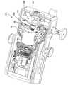
도 2 에 도시된 바와 같이, 통상적인 프로브(105)는 니들(10), 커터(50), 니들방향인디케이터(needle orientation indicator)(65), 섬휠(60), 진공매니폴드(70), 커터회전및변환메터니즘(80), 드라이브기어(85)를 포함하는 기어멤버(84), 회전가능한 매니폴드(144)를 포함하는 샘플홀더(140), 및 홀더기어(170)을 일반적으로 포함한다. 상기 프로브(105)의 다른 형태들은 687특허에서 도시되고 설명된 바 있으며, 그것들은 여기에서 참조적으로 통합된다, 통상적인 홀스터(205)는 리세스(recess)(204), 커터드라이브메커니즘(210), 중계구동기어(intermediate driven gear)(238), 조직샘플홀더회전메커니즘(242), 인코더어셈블리(240, 253), 홀더드라이브기어(251), 및 드라이브케이블(215)을 일반적으로 포함한다. 통상적인 홀스터(205)의 다른 형태는 687 특허에서 도시되고 설명된 바 있으며, 그것들은 여기에서 참조적으로 통합된다. 상기 프로브(105)는 홀스터(205)에 연결되어, 섬휠(60)은 리세스(204)에 안착되고, 드라이브기어(85)는 구동기어(238)와 맞물리며, 홀더기어(170)는 홀더드라이브기어(251)과 맞물린다. 체결이 이뤄진 다음에, 상기 매니폴드(144)의 회전 위치는 압전모터(piezoelectric motor)(250)에 의해 제어된다. 각각의 조직샘플들이 비어있는 챔버로 수용되고 새로운 챔버가 정렬된 후에 소프트웨어 또는 제어로직에 의해 자동적으로 매니폴드(144)은 재배치된다. 조직샘플을 획득하기 위하여, 오퍼레이터(작업자)는 니들(10)과 니들방향인디케이터(65)를 회전시키도록 섬휠(60)을 회전시킨다. 커터(50)는 절개해 내기 위하여 커터드라이브메커니즘(80)을 경유하여 회전되며 직동된다(translated). 그 뒤에, 튜브(502)에 의하여 조직샘플홀더(140)는 진공이 적용됨에 따라, 절개된 조직샘플은 커터의 루멘(lumen: 내강)에서 조직샘플통로(tissue sample passage)(54)로 빨려들어가고, 최종적으로 정렬된 조직샘플챔버(tissue sample chamber)에 저장된다. 커터드라이브메커니즘(80), 커터모터(530), 모터컨트롤러(540) 및 아이들러샤프트엔코더조립체(idler shaft encoder assembly)(240, 253)의 작동을 포함한 상기 과정의 세부 사항은 687특허에 상세히 설명되어 있으며, 여기에서 통합된다.As shown in FIG. 2, a
687특허에는 도 3 과 4 에 도시된 바와 같이 정위적 셋팅(stereotactic setting)에서 사용되도록 구성된 홀스터(705)가 설명되었으며, 이 것은 여기에서 참조적으로 통합된다. 상기 홀스터(705)는 (도 2 의) 프로브(105)와 결합된다. 상기 프로브는 2012. 8. 28 자로 공고된 미국특허 제 8,251,916 호(여기에서 이후에는 916특허)로써 설명된 바 있으며, 여기에서 참조적으로 통합되되 다른 적합한 프로브가 사용될 수 있다. 홀스터(705)는 상부하우징멤버(707), 하부하우징멤버(708) 및 니들발사포크(needle firing fork)(790)을 포함한다. 니들발사포크(790)는 홀스터(705)에서 말단쪽으로 확장되는 니들발사샤프트(needle firing shaft)(710)의 말단에 위치된다. 홀스터(705)는 상부하우징멤버(707)에서 확장되고, 프로브(105)를 홀스터(705)에 탈거가능하게 고정시킬 수 있는 후크멤버들(714)를 추가적으로 더 포함한다.The 687 patent describes a
상부하우징멤버(707)은 섬휠기어(750)가 접하게 되는 리세스(704)를 더 포함한다. 섬휠기어(750)은 프로브(105)가 홀스터(705)와 연결될 때 섬휠(60)에 맞물리도록 배치된다. 특히, 섬휠기어(750)는 프로브(105)가 홀스터(705)와 연결될 때 섬휠(60)의 수동적인 회전에 대응하여 회전할 수 있도록 동작한다. 섬휠기어(750)는 섬휠(60)의 방향과 반대방향으로 회전한다. 조직샘플홀더드라이브기어(751)는 홀스터(705)의 근위말단(proximal end)에서 부터 확장한다. 상기 조직샘플홀더드라이브기어(751)은 프로브(105)가 홀스터(705)와 결합될 때 조직샘플홀더(140)의 매니폴드(144)를 회전시키도록 작동한다.The
도 4 에 도시된 바와 같이, 링킹메커니즘(linking mechanism)(740)은 섬휠기어(750)를 (조직샘플홀더드라이브)기어(751)에 연결한다. 특히, 링킹메커니즘(740)은 섬휠기어(750)의 회전에 대응하여 (조직샘플홀더드라이브)기어(751)의 회전이 야기되도록 구성된다. 이 실시예에의 링킹메커니즘(740)은 섬휠기어(750) 근방에서 확장된 샤프트(720)을 포함한다. 또 다른 기어(722)는 샤프트(720)에 고정된다. 따라서, 그 기어(722)는 샤프트(720) 및 섬휠기어(750)와 함께 회전한다. 또한, 그 기어(722)는 도면번호 726 기어와 맞물린 도면번호 724 기어와도 맞물린다. 따라서, 도면번호 726 기어는 도면번호 722, 724 기어들과 함께 회전하되, 도면번호 722 기어와 동일한 방향으로 회전한다. 도면번호 728 샤프트는 도면번호 726 기어 근방에서 확장된다. 또 다른 도면번호 730 기어는 도면번호 728 샤프트에 고정된다. 따라서, 도면번호 730 기어는 도면번호 728 샤프트 및 도면번호 726 기어와 함께 회전한다. 아울러, 도면번호 730 기어는 도면번호 732 기어와 맞물린다. 상기 도면번호 732 기어 근방에서는 도면번호 734 샤프트가 확장된다. 또 다른 도면번호 736 기어는 홀스터(705)의 말단에 위치에서 도면번호 734 샤프트에 고정된다. 따라서, 도면번호 736 기어는 도면번호 734 샤프트 및 도면번호 730, 732 기어들과 함께 회전한다. 아울러, 도면번호 736 기어는 도면번호 740 기어와 또한 맞물리는 도면번호 738 기어와 맞물린다. 따라서, 도면번호 740 기어는 도면번호 736 기어와 같은 방향으로 도면번호 736, 738 기어들과 함께 회전한다. 도면번호 724 샤프트는 도면번호 740 기어와 751 기어를 연결한다. 그러므로, 섬휠기어(750)는 도번부호 722, 724, 726, 730, 732, 736, 738, 740 기어들 및 도면번호 720, 728, 734, 742 샤프트들을 통해 (조직샘플홀더드라이브)기어(751)에 연결된다.As shown in FIG. 4, a
또한, 도시되지는 않았지만 커터드라이브메커니즘이 홀스터(705) 내에 제공된다. 특히, 상기 커터드라이브메커니즘은 상부하우징멤버(707)을 통해 나타나는 도번번호 238 기어를 회전시키도록 작동가능하다. 상기 도면번호 238 기어는 프로브(105)가 홀스터(705)에 연결될 때 도면번호 85 기어에 맞물리도록 배치된다. 따라서, 프로브(105)가 홀스터(705)에 연결될 때 도면번호 238 기어의 회전은 커터(50)의 회전과 병진(translation)을 야기한다. 홀스터(705)에서 실시되는 커터드라이브메커니즘의 작동을 위한 바람직한 구성요소, 특징, 배열, 방법들은 916특허에 설명된 바 있으며, 거기에서 공개된 내용들은 여기에서 참조적으로 통합된다.Also, although not shown, a cutter drive mechanism is provided in the
또한, 도시되지는 않았으나 니들발사메커니즘이 홀스터(705) 내에 제공된다. 특히, 상기 니들발사메커니즘은 홀스터(705)에서 상대적인 길이방향을 따라 샤프트(710)와 포크(790)가 병진을 야기하도록(연동하여 작동하도록) 동작될 수 있다. 상기 포크(790)는 니들부(10)에 맞물리게 배치되어, 프로브(105)가 홀스터(705)에 결합될 때 상기 니들부(10)는 샤프트(710) 및 포크(790)와 함께 길이방향을 따라 병진할 것이다. 상대적인 길이방향으로 상기 니들부(10)가 프로브(105)의 다른 구성요소들을 병진시키는 것을 허용하기 위하여 프로브(105)의 적합한 변형이 있을 수 있으며, 이는 이분야의 당업자라면 명백히 알 수 있을 것이다. 양자택일적으로, 여기에서 참조적으로 통합되어 공개된 916특허에서 개시되는 특정 프로브는 포크(790)에 의해 결합되거나 병진하는 그것의 니들부를 가질 것이다. 다른 경우로써, 상기 니들부(10)의 발사는 가슴 조직 또는 다른 조직으로 니들부(10)를 강력하게 추진시키는 것으로써 요구될 것이다. 홀스터(705) 내의 구성요소 중 하나로써 니들발사메커니즘의 구성요소, 특징, 배치, 동작방법들은 916특허에서 설명되며, 이 것은 여기에서 참조적으로 통합된다.Also, although not shown, a needle firing mechanism is provided in the
위의 구조는 687 특허에 의해 설명된 바 있으나, 섬휠기어(750)와 도면번호 751 기어의 결합에서 분리는 허용되지 않았다. 아울러, 연결된 모터가 섬휠기어(750)와 도면번호 751 기어 둘 모두의 회전을 제어하는 것이 허용되지 않았다.The above structure has been described by the 687 patent, but separation was not permitted in the combination of the
도 5 에는 본 발명의 바람직한 실시예에 따라 홀더드라이브기어(holder drive gear)를 갖는 프로브의 섬휠의 선택적인 연결이 허용되는 홀스터(805)가 도시되었다. 상기 홀스터(805)는 프로브(105)와 연결되되 상기 프로브는 916특허에서 설명된 것으로써 여기에서 참조적으로 통합되거나 다른 적합한 프로브가 될 수도 있다. 상기 홀스터(805)는 상부하우징멤버(807), 하부하우징멤버(808) 및 니들발사포크(890)을 포함한다. 상기 니들발사포크(890)는 홀스터(805)에서 확장되는 니들발사샤프트(810)의 말단에 위치한다. 추가적으로 상기 홀스터(805)는 상부하우징멤버(807)에서 확장되는 후크멤버들(814)을 더 포함하며, 이것들은 프로브를 홀스터에 탈거가능하게(분리가능하게) 고정시킬 수 있다.5 shows a
상부하우징멤버(807)는 섬휠기어(850)가 접하는 리세스(804)를 추가적으로 포함한다. 상기 섬휠기어(850)는 프로브(105)가 홀스터(805)와 결합될 때 섬휠(60)과 맞물리도록 구성된다. 특히, 프로브(105)가 홀스터(805)와 결합될 때 섬휠기어(850)는 섬휠(60)의 수동 회전에 상응하여 회전하도록 작동가능하다. 조직샘플홀더드라이브기어(851)은 홀스터(805)의 말단에서부터 확장된다. 상기 조직샘플홀더드라이브기어(851)는 조직샘플홀더(140)의 기어(170)와 맞물리도록 구성된다. 특히, 상기 조직샘플홀더드라이브기어(851)는 프로브(105)가 홀스터(805)와 결합될 때 조직샘플홀더(140)의 매니폴드(144)를 회전시키도록 동작가능하다.The
도 6 과 7 은 정위적홀스터(805)의 사시도를 도시한 것이되, 링킹메커니즘과 선택적 맞물림메커니즘(engagement mechanism)의 구성요소들이 생략된 상태로 도시되었다. 링킹메커니즘(815)는 섬휠기어(850)를 조직샘플홀더드라이브기어(851)에 선택적으로 연결시킨다. 특히, 선택적 맞물림메커니즘(860)을 구비한 상기 링킹메커니즘(815)은 섬휠기어(850)의 회전에 대응하여 조직샘플홀더드라이브기어(851)의 회전이 선택적으로 이뤄지도록 구성된다. 이 실시예의 링킹메커니즘(815)는 섬휠기어(850) 근방에서부터 확장된 샤프트(820)을 포함한다. 다른 기어(822)가 샤프트(820)에 고정된다. 따라서, 도면번호 822 기어는 샤프트(820) 및 섬휠기어(850)와 같이 회전한다. 또한, 도면번호 822 기어는 도면번호 826 기어와도 맞물리는 도면번호 824 기어와 맞물린다. 따라서 도면번호 826 기어는 도면번호 822, 824 기어들과 함께 회전한다. 도면번호 826 기어에서는 도면번호 828 샤프트가 확장된다. 또 다른 기어인 도면번호 830 기어는 도면번호 828 샤프트에 고정된다. 따라서, 도면번호 830 기어는 도면번호 828 샤프트 및 도면번호 826 기어와 함께 회전한다. 아울러, 도면번호 830 기어는 도면번호 832 기어와 맞물린다. 도면번호 834 샤프트는 도면번호 832 기어에서 확장된다. 또 다른 기어인 도면번호 836 기어는 도면번호 834 샤프트에 고정된다. 따라서, 도면번호 836 기어는 도면번호 834 샤프트 및 도면번호 830, 832 기어들과 함게 회전한다. 도면번호 836 기어는 도면번호 838 기어와 맞물린다. 도면번호 838 기어는 도면번호 840 기어에 선택적으로 맞물린다. 도면번호 838 기어가 도면번호 840 기어에 맞물리게 선택되면, 도면번호 840 기어는 도면번호 836, 838 기어들과 함께 회전한다. 도면번호 842 샤프트는 도면번호 840 기어와 도면번호 851 기어를 연결한다. 따라서, 도면번호 838 기어가 도면번호 840 기어에 맞물리도록 선택되면, 섬휠기어(850)은 도면번호 822, 824, 826, 830, 832, 836, 838, 840 의 기어들 및 도면번호 820, 828, 834, 842 의 샤프트들을 통하여 조직샘플홀더드라이브기어(851)에 연결된다. 그러나, 도면번호 838 기어가 도면번호 840 기어에 맞물리지 않도록 선택된다면, 상기 섬휠기어(850)는 조직샘플홀더드라이브기어(851)와 연결되지 않는다. 따라서, 맞물리지 않는 상태에 있을 경우, 섬휠(60)의 회전은 조직샘플홀더드라이브기어(851)를 통한 조직샘플홀더(140)의 회전으로 연결되지 않을 것이다.6 and 7 illustrate perspective views of
도면번호 840 기어와 도면번호 838 기어의 선택적 맞물림은 선택적 맞물림메커니즘(860)의 활성화(작동)에 의해서 발생한다. 도 6 내지 8 에 도시된 바와 같이, 선택적 맞물림메커니즘(860)은 샤프트(834)의 끝단에 회전가능하게 연결된 브라켓(862)를 포함할 수 있다. 상기 브라켓(862)은 수용홀들(receiving holes)(866)을 통해 샤프트(834)를 관통하도록 상기 샤프트(834)에 결합될 수 있다. 클립(868)은 브라켓(862)이 샤프트(834)에 안정적으로 결합된 것을 보증하기 위하여 제공될 수 있다. 상기 브라켓(862)은 한 쌍의 유지부들(retaining features)(870)을 수용하기 위하여 도면번호 838 기어 근방에 위치한 한 쌍의 트로프들(troughs: 파인부분)(864)를 포함한다. 상기 유지부들(870)과 도면번호 838 기어는 도면번호 872 샤프트에 고정될 것이다. 도면번호 838 기어는 상기 한 쌍의 유지부들(870) 사이에 위치될 것이다. 상기 유지부들(870)은 트로프들(864)에 끼워지나, 도면번호 872 샤프트 및 도면번호 838 기어와 함께 자유롭게 회전될 수 있다. 도면번호 838 기어는 도면번호 836 기어와 맞물리기 때문에 도면번호 836 기어의 회전은 도면번호 838 기어를 회전시킨다. 상기 선택적 맞물림메커니즘(860)은 돌기(876)를 갖는 플런저(plunger)(878)을 더 포함한다. 상기 브라켓은 플런저(878)와 맞춰질 수 있는 수용부(receiving portion)(874)를 갖는 자유단(free end)를 포함한다. 여기에서 사용됨에 있어서, 상기 수용부(874)와 플런저(878)가 서로 맞춰질 수 있는 방식은 플런저(878)에 맞춰지는 것이 허용되도록 수용부(874)가 적합한 모양을 갖는 것을 포함한다. 예를 들어, 상기 수용부(874)는 플런저(878)의 돌기(876)와 상호작용하는 모양으로 형성될 수 있다. 선택적 맞물림메커니즘(860)은 맞물린 위치로 상기 브라켓(862)을 (일측으로) 치우치게 하기 위한 브라켓바이어싱멤버(bracket biasing member)(880)를 포함할 수 있다. 상기 플런저(878)는 브라켓(862)에서 떨어져 플런저(878)를 치우치게 하기 위한 플런저바이어싱멤버를 포함할 수 있다. 본 발명의 다른 실시예로써, 상기 브라켓바이어싱멤버(880)는 한개만으로 브라켓에서 플런저의 돌기(876)를 치우치게하기 충분한다.The selective engagement of the
상기 선택적 맞물림메커니즘(860)의 작동을 설명할 것이다. 이탈 상태인 도 7 에 도시된 바와 같이, 브라켓바이어싱멤버(880)은 브라켓(862)를 윗쪽으로(즉, 프로브를 향한 방향으로) 치우치게 하여, 도면번호 838 기어는 도면번호 840 기어에 맞물린다. 또한, 도 7 에 도시된 바와 같이, 플런저(878)는 완전하게 당겨져서, 플런저의 돌기(876)는 홀스터(805)의 측벽면으로 후퇴한다. 이 상태에서는 도면번호 840 에 도면번호 838 기어가 맞물려 있기 때문에, 섬휠(60)의 운동은 홀더드라이브기어(851)로 전달될 것이고, 그 다음으로 그 운동은 위에 설명된 방식으로 조직샘플홀더로 전달될 것이다. 따라서, 이탈 상태에서는, 섬휠의 회전이 샘플홀더의 회전에 직접적으로 연결된다. 섬휠의 회전이 더 이상 샘플홀더의 회전으로 연결되지 않도록 조작자가 연결이 차단되기를 원할 때, 조작자는 플런저(878)을 누른다. 조작자가 플런저(878)를 누름에 따라서, 플런저의 돌기(876)는 홀스터의 측벽면에서 이탈하도록 이동하고, 브라켓(862)의 수용부(874)를 향하여 이동한다. 이러한 힘은 플런저(878)를 당겨진 위치로 치우치게 하는 플런저바이싱메커니즘을 극복하는 것을 포함한다. 상기 플런저의 돌기(876)가 수용부(874)에 접촉할 때, 브라켓(862)에 저항하는 연속된 힘은 아랫쪽(즉, 프로브와 이탈되는 방향)으로 분배된다. 예를 들어, 도 7 에 도시된 바와 같이, 플런저의 돌기(876)와 브라켓의 수용부(874)는 경사지게 형성되어, 플런저(878)의 전진운동이 브라켓 수용부(874)에 맞닿으면 아랫쪽으로 힘이 나눠진다. 브라켓(862)의 일측 끝단은 샤프트(834)에 회전가능하게 연결되었기 때문에, 아랫쪽을 향하는 힘은 샤프트(834)의 근방에서 브라켓(862)의 회전을 야기한다. 또한, 브라켓(862)의 트로프들(864) 내에 배치된 유지부들(870)은 상기 유지부들(870)에 연결된 도면번호 838 기어를 따라 브라켓(862)의 회전과 함께 이동한다. 상기 브라켓(862)이 회전하면, 도면번호 838 기어는 더이상 도면번호 840 기어와 맞물리지 않는다. 기어들이 맞물리지 않는 위치에 놓임에 따라, 섬휠(60)은 홀더드라이브기어(851) 또는 샘플홀더매니폴드(144)와 더 이상 연결되지 않는다. 따라서, 섬휠의 운동은 샘플홀더매니폴드(144)의 회전 운동으로 분배되지 않을 것이다. 유사한 경우로써, 조식샘플홀더매니폴드(144)의 (아래에서 더 상세히 설명될) 모터회전은 섬휠(60)의 회전운동으로 분배되지 않을 것이다. 따라서, 섬휠(60)은 샘플을 수용할 격실(compartment)의 변경 없이도 자유롭게 회전될 수 있으며, 조직샘플홀더매니폴드(144)는 섬휠(60) 또는 니들(10)의 방향 변경 없이도 자유롭게 회전될 수 있다. 플런저(878)가 완전하게 활성화된(눌려진) 이러한 위치에서, 도면번호 838 기어는 도 8 에 도시된 바와 같이 더 이상 도면번호 840 기어와 맞물리지 않는다.The operation of the
플런저(878)는 리테이닝메커니즘(retaining mechanism)(882)을 포함하므로, 조작자가 플런저(878)에 힘을 가하는 것을 멈춘 후에도 상기 플런저(878)는 눌려진 상태가 유지될 것이다. 예를 들어, 상기 리테이닝메커니즘(882)는 핀(884)과 L 자 모양의 슬롯(886)을 포함한다. 플런저(878)가 완전히 눌린 후에, 상기 핀(884)는 L 자 모양의 슬롯(886)의 축부(axial portion)(888)의 후방(즉, 상기 축부(888)가 원주부(circumferential portion)(890)와 만나는 지점)에 위치될 것이다. 그리고, 조작자가 플런저(878)를 회전시키면 상기 핀(884)은 L 자 모양 슬롯(886)의 원주부(890)에 위치하게 된다. 이 위치에 놓이게 될 때, 조작자가 플런저(878)를 원래의 위치로 회전시키기 전까지 상기 핀(884)은 플런저(878)가 앞쪽 또는 뒷쪽으로 움직이는 것을 차단한다.The
도 9 에는 본 발명의 다른 실시예에 따른 선택적 맞물림메커니즘(960)을 도시하였다. 선택적 맞물림메커니즘(960)은 샤프트(934)의 끝단으로 활주가능하게 연결된 브라켓(962)을 포함한다. 상기 브라켓(962)는 수용홀들(966)을 통해 샤프트(934)를 관통함으로써 상기 샤프트(934)에 장착된다. 상기 브라켓(962)은 한 쌍의 유지부(970)를 수용하기 위해 도면번호 938 기어에 근접배치된 한 쌍의 트로프들(964)를 포함한다. 상기 유지부들(970)과 도면번호 938 기어는 도면번호 972 샤프트에 부착된다. 상기 도면번호 938 기어는 한 쌍의 유지부들(970) 사이에 위치하게 된다. 상기 유지부들(970)은 트로프들(964) 내에 안착되나, 도면번호 972 샤프트와 도면번호 938 기어와 같이 자유롭게 회전이 가능하다. 도면번호 938 기어와 도면번호 936 기어는 맞물려 있기 때문에, 도면번호 936 기어의 회전은 도면번호 938 기어를 회전시킨다. 추가적으로, 상기 선택적 맞물림메커니즘(960)은 돌기(976)를 갖는 플런저(978)를 더 포함한다. 상기 브라켓은 플런저(978)의 돌기부(976)와 상호작용하는 모양으로 형성된 수용부(974)를 갖는 자유단을 포함한다. 상기 선택적 맞물림메커니즘(960)은 맞물림 위치로 상기 브라켓(962)을 치우치게 하기 위한 브라켓바이어싱멤버(980)을 포함한다. 도 9 에 도시된 바와 같이, 상기 브라켓바이어싱멤버(980)는 도면번호 934 샤프트를 둘러싸며, 브라켓(962)의 일부분에 접하게 된다.9 shows an
상기 선택적 맞물림메커니즘(960)의 작동은 하기와 같이 설명된다. 브라켓바이어싱멤버(980)는 브라켓(962)를 윗쪽(즉, 니들을 향하는 방향)으로 치우치게 하여 도면번호 938 기어는 도면번호 940 기어와 맞물린다. 또한, 도 9 에 도시된 바와 같이, 상기 플런저(978)는 완전히 당겨지며, 플런저의 돌기(976)은 홀스터(905)의 측벽면으로 당겨진다. 이 위치에서, 도면번호 938 기어가 도면번호 940 기어와 맞물리기 때문에 섬휠(60)의 회전은 조직샘플홀더드라이브기어(미도시)의 회전으로 전달되며, 그 다음으로 위에 설명한 바와 같은 방식에 따라 조직샘플홀더로 회전이 전달된다. 따라서, 기본 위치에 있을 때, 섬휠의 회전은 샘플홀더의 회전으로 직접적으로 연결된다. 섬휠의 회전이 조직샘플홀더의 회전으로 연결되는 것을 더 이상 원하지 않아서 연결을 끊코자 할 때, 조작자는 플런저(978)를 누른다. 조작자가 상기 플런저(978)을 누름에 따라, 플런저의 돌기(976)는 홀스터의 측벽면을 이탈해 브라켓(962)의 수용부(974)를 향하여 이동한다. 이러한 힘은 플런저(978)가 당겨진 위치에 놓이도록 치우치게 하는 플런저바이어싱메커니즘을 극복하는 것을 포함한다. 플런저의 돌기(976)가 수용부(974)에 접촉하면, 브라켓(962)에 대응하는 연속적인 힘은 브라켓에서 아랫쪽(즉, 니들에서 떨어지는 쪽)으로의 힘으로 분배된다. 예를 들어, 상기 플런저의 돌기(976)와 브라켓의 수용부(974)는 플런저(978)의 전진운동이 브라켓의 수용부(974)에 접촉하면 아랫쪽으로 향하는 힘으로 분배되도록 경사진 모양으로 형성된다. 상기 브라켓(962)의 일측 끝단은 샤프트(934)에서 활주가능하게 결합되어 있으므로, 이러한 아랫쪽을 향하는 힘은 샤프트(934)를 따라 니들에서 멀어지는 방향으로 브라켓(962)를 활주시킨다. 브라켓(962)의 트로프들(964) 내에 배치되며 도면번호 938 기어에 연결된 상기 유지부(970)는 또한 상기 브라켓(962)의 활주에 함께 이동한다. 도면번호 938 기어가 홀스터의 후방쪽으로 이동하면, 도면번호 938 기어는 도면번호 940, 936 기어들과 더 이상 맞물리지 않는다. 상기 기어들이 맞물리지 않게 됨에 따라서, 섬휠(60)은 홀더드라이브기어 또는 조직샘플홀더매니폴드(144)와는 더 이상 연결되지 않는다. 따라서, 섬휠(60)의 운동은 조직샘플홀더매니폴드(144)의 회전운동으로 분배되지 않을 것이다. 유사한 방식으로써, 조직샘플홀더매니폴드(144)의 (이후에 상세히 설명될) 모터 회전은 섬휠(60)에서의 회전운동과 분리될 것이다. 그러므로, 상기 섬휠(60)은 샘플을 수용할 격실의 변경 없이도 자유롭게 회전될 수 있으며, 조직샘플홀더매니폴드(144)는 섬휠(60) 또는 니들(10)의 방향 변경 없이도 자유롭게 회전될 수 있다.The operation of the
상기 플런저(978)는 조작자가 플런저(978)를 누르는 힘을 멈춘 후에도 눌려진 위치를 유지시키기 위한 리테이닝메커니즘(982)를 포함한다. 예를 들면, 상기 리테이닝메커니즘(982)은 핀(984)과 L 자 모양의 슬롯(986)을 포함한다. 플런저(978)가 완전히 눌려지면, 상기 핀(984)은 L 자 모양의 슬롯(986)의 축부의 후방쪽(즉, 축부와 원주부가 만나는 지점)에 위치될 것이다. 그 다음으로, 핀(984)이 L 자모양 슬롯의 원주부에 위치하도록 조작자는 플런저(978)를 회전시킨다. 이 위치에 놓이게 됐을 때, 상기 핀(984)은 조작자가 플런저(978)를 원래의 위치로 회전시키기 전까지 상기 플런저(978)의 전방 또는 후방으로의 이동을 차단한다.The
상기 선택적 맞물림메커니즘(860, 960)은 섬휠(60)이 조직샘플홀더(140)에 연결되어야 할 때, 조작자가 선택할 수 있는 기능을 제공한다. 이는 조작자가 섬휠(60)의 회전을 조직샘플홀더매니폴드(144)에 1:1로 연결시키는 것에 대한 유연성과 필요에 따라 회전의 연결을 차단하는 것에 대한 유연성을 갖는 것을 허용한다. 예를 들어, 조작자는 (샘플을 계속 채취하는 동한 연결을 차단함으로써) 동일한 조직격벽(tissue compartment) 내에 여러 개의 샘플을 넣을 수 있거나, (연결을 차단하고 이전의 방향으로 니들을 회전시킴으로써) 조직샘플홀더의 회전없이도 이전의 니들 방향으로 되돌릴 수 있다. 다른 예로써, 조작자는 플런저(878)을 누름으로써 조직샘플홀더매니폴드(144)에서 섬휠(60)의 연결을 끊을 수 있고, 조직샘플홀더매니폴드(144) 내에서 샘플의 질을 확인하기 위하여 니들(10)을 회전시킬 필요없이 조직샘플홀더매니폴드(144)만 회전시킨다. 그 다음으로, 조작자는 플런저(878, 978)의 눌림이 유지되는 동안 조직샘플홀더매니폴드(144)를 원래의 위치 또는 다른 위치로 회전시킬 수 있고, 연결이 다시 이뤄지도록 상기 플런저는 당겨진 위치(원위치)로 복귀가 허용된다.The
도 10 에 도시된 바와 같이, 조직샘플홀더의 회전은 홀스터(805) 내에 장착된 압전모터(piezoelectric motor) 등와 같은 모터(892)에 의해 제어된다. 상기 모터(892)는 도면번호 896 기어와 연결된 도면번호 894 샤프트를 갖는다. 상기 기어(896)은 도면번호 840 기어와 맞물린다. 상기 모터(892)가 작동하면, 상기 샤프트(894)는 도면번호 896 기어를 함께 회전시킨다. 상기 기어(896)가 도면번호 840 기어와 맞물리기 때문에, 모터(892)의 작동은 도면번호 851 기어의 회전을 야기하는 도면번호 840 기어의 회전으로 전달된다. 따라서, 홀더기어(170)와 홀더드라이브기어(851)이 맞물리도록 홀스터(805)와 프로브가 결합되고 모터(892)가 작동될 때, 매니폴드(144)는 조직샘플홀더(140) 내에서 회전된다. 상기 선택적 맞물림메커니즘(860)은 도면번호 838 기어가 도면번호 840 기어와 맞물리도록 구성되어, 마찬가지로 모터(892)의 작동은 링킹메커니즘(815)을 통해 섬휠(60)과 니들(10)을 회전시킨다. 따라서, 모터(892)의 컴퓨터 제어를 통하여 매니폴드(144) 및 니들(10)의 회전은 완전하게 자동적이고 연동적으로 구성될 수 있다. 상기 선택적 맞물림메커니즘(860)이 도면번호 838 기어가 도면번호 840 기어가 맞물리지 않도록 구성될 때, 섬휠(60)을 경유하여 개별적으로 회전되지 않는다면 니들(10)은 회전하지 않는 상태를 유지할 것이며 그 동안 모터(892)의 구동력은 매니폴드(144)의 회전으로만 분배될 것이다. 또한, 도 10 에 도시된 것과 유사한 방식으로 상기 모터는 홀스터(905) 내에서 (비슷한) 기능을 한다.As shown in FIG. 10, the rotation of the tissue sample holder is controlled by a
유사한 방식으로써, 본 발명의 실시예에서, 상기 선택적 맞물림메커니즘(860, 960)의 작동(즉, 상기 플런저(878, 978)의 누름 및/또는 회전)은 컴퓨터 제어를 통하여 수행될 수도 있다. 도시되지는 않았지만, 전기기계적인(electromechanically) 공지의 방식으로 플런저(878, 978)의 누름이 수행될 수도 있다. 컴퓨터 명령의 입력을 통하여 소프트웨어는 사용자가 상기 선택적 맞물림메커니즘(860, 960)을 구동시키는 것을 허용한다. 추가적으로, 상기 소프트웨어는 미리정의된 변수들에 따라 상기 선택적 맞물림메커니즘(860, 960)을 자동적으로 구동시킬 수 있도록 프로그램될 수 있다. 따라서, 섬휠(60)와 홀더기어(851) 사이를 선택적으로 연결하거나 차단하는 구성에 있어서는 모터(892)의 구동을 제어하는 컴퓨터 소프트웨어의 실행에 의해서 매우 다양한 선택적인 옵션들을 이용할 수 있다.In a similar manner, in an embodiment of the present invention, the actuation of the
예를 들면, 첫번째 세팅으로써, 컴퓨터 컨트롤러는 도면번호 838, 938 기어들과 도면번호 840, 940 기어들이 맞물리게 구성되도록 상기 선택적 맞물림메커니즘(860, 960)을 유지시킬 것이다. 이러한 세팅에 있어서, 상기 컴퓨터 컨트롤러가 모터를 구동시킬 때, 매니폴드(144)의 회전은 니들의 회전과 1:1로 매치될 것이다. 이러한 첫번째 세팅은 니들(10)의 각각의 시간위치(o'clock position)가 매니폴드의 각각의 시간위치와 자동적으로 대응되는 지점에서 완전히 자동적으로 샘플링하는 것을 허용한다. 예를 들면, 니들(10)의 한 시 위치에 있을 때, 샘플은 매니폴드가 한 시 위치에 놓이지는 지점에서 수집되고 저장된다.For example, as a first setting, the computer controller will maintain the
여기에서 사용되는 니들의 "시간위치"는 아날로그 시계의 전면에 놓이는 시간에 대응하여 샘플을 수집하기 위해 니들의 구멍(aperture)이 위치하는 니들의 방향(orientaion)을 의미한다. 예를들어, 12 시 위치에서, 니들의 구멍은 환자의 머리를 향하여 윗쪽을 향하게 된다. 그리고, 상기 니들이 12 시 위치에서부터 시계방향으로 대략 30도 정도 회전되면, 두번째 위치는 1 시 위치가 된다. 니들의 연속된 각각의 회전들은 시간위치에 대응하며, 시간위치는 니들이 완전하게 한번 회전했을 때 정의되는 12 개의 위치들을 갖는다. 여기에서는 상기 니들의 위치들이 일반적으로 시간위치로써 언급되겠지만, 위치들의 갯수는 위치들 사이에 더 큰 각도나 더 작은 각도가 제공됨에 따라서 다양한 갯수로 정해질 수 있음을 이해할 수 있을 것이다. 예를 들어, 연속된 각각의 위치가 15도 회전으로 정의된다면, 니들이 완전하게 한번 회전했을 때 24 개의 연속된 위치들을 가질 것이다. 비슷한 경우로, 연속된 각각의 위치가 60도 회전으로 정의된다면, 니들이 완전하게 한번 회전했을 때 6 개의 연속된 위치들을 가질 것이다. 추가적으로, 각각의 위치들 사이의 회전 각도는 (반드시) 일정하게 정해질 필요가 없다. 예를들어, 첫번째 위치와 두번째 위치 사이의 회전각도는 15도로 정해질 수 있지만 두번째 위치와 세번째 위치 사이의 회전 각도는 30도로 정해질 수 있다. 유사한 방식으로 상기 매니폴드는 니들의 시간위치에 대응하여 지정되는 '시간위치'를 갖는 다수 개의 챔버들(chambers)을 가질 것이다. 예를들어, 12 시 위치로 정해진 매니폴드의 챔버는 니들의 12 시 위치에 대응한다. 이러한 예에서, 니들의 구멍은 환자의 머리를 향하여 윗쪽으로(즉, 12 시 위치로) 향하게 되고, 이러한 니들의 특정 위치에서 채취된 조직을 수용하기 위한 매니폴드의 챔버는 12 시의 챔버(12 시 위치에 대응하는 챔버)가 된다. 상기 매니폴드는 동일한 크기를 갖는 다수 개의 챔버들로 분할된 일반적인 원통형 모양을 가질 수 있다. 상기 챔버들이 니들의 각 위치들에 대응함에 따라서 또한, 상기 챔버들은 연속된 전체의 갯수가 동일한 갯수로 정해질 것이다. 니들의 위치들과 함께하는 매니폴드 내의 챔버의 갯수는 다양하게 구성될 수 있지만, 일반적으로는 니들 위치들의 갯수와 동일하게 구성된다. 예를 들어, 니들의 위치가 24 개로 정해지면, 매니폴드는 24 개의 챔버들을 가질 것이다.As used herein, the "time position" of the needle refers to the orientation of the needle where the aperture of the needle is positioned to collect the sample corresponding to the time placed on the front of the analog clock. For example, at the twelve o'clock position, the hole in the needle is pointed upwards towards the patient's head. Then, when the needle is rotated about 30 degrees clockwise from the 12 o'clock position, the second position becomes the 1 o'clock position. Each successive rotation of the needle corresponds to a time position, the time position having twelve positions defined when the needle has rotated completely once. Although the positions of the needles will generally be referred to as time positions, it will be appreciated that the number of positions can be determined in various numbers as a larger or smaller angle is provided between the positions. For example, if each successive position is defined as a 15 degree rotation, the needle will have 24 consecutive positions when rotated once. Similarly, if each successive position is defined as a 60 degree rotation, the needle will have six consecutive positions when rotated once. In addition, the angle of rotation between each of the positions does not necessarily have to be constant. For example, the rotation angle between the first position and the second position may be set to 15 degrees, but the rotation angle between the second position and the third position may be set to 30 degrees. In a similar manner the manifold will have a plurality of chambers having a 'time position' which is designated corresponding to the time position of the needle. For example, the chamber of the manifold set to the twelve o'clock position corresponds to the twelve o'clock position of the needle. In this example, the hole of the needle is directed upwards (ie, at the 12 o'clock position) towards the patient's head, and the chamber of the manifold for receiving the tissue collected at the specific position of the needle is a chamber at 12 o'clock. Chamber corresponding to the time position). The manifold may have a general cylindrical shape divided into a plurality of chambers having the same size. Also, as the chambers correspond to respective positions of the needles, the chambers will be set to the same number of consecutive wholes. The number of chambers in the manifold along with the needle positions can vary, but is generally the same as the number of needle positions. For example, if the needle is positioned at 24, the manifold will have 24 chambers.
여기에서 사용됨에 있어서, "매니폴드의 위치"는 진공된(vacuumed) 조직샘플을 수용하기 위해 샘플조직통로(sample tissue passageway)와 정렬되는 제공된 시간 위치와 관계된 특정한 조직샘플챔버를 의미한다. 예를들어, "매니폴드의 1시 위치"는 1시 위치와 연계된 조직샘플챔버가 샘플조직통로와 정렬되고 진공이 생성되면 조직샘플을 수용하는 것을 의미한다. 그 다음으로, 컴퓨터 컨트롤러는 니들(10)과 매니폴드(144)가 동시에 회전하여 두 개 모두가 2시 위치에 놓일 때까지 모터를 구동시킬 것이다. 그리고, 새로운 샘플이 채집될 것이다. 이러한 과정은 필요에 따라서 여러 시간 위치들 (또는 다른 증분과정들[incremental steps])에서 자동적으로 연속될 것이다. 그러므로, 이와 같은 셋팅에 있어서, 샘플들은 자동적으로 연속된 순서(즉, 1시 위치, 2시 위치, 3시 위치 등)에 따라 자동적으로 채취될 수 있다.As used herein, “position of manifold” refers to a specific tissue sample chamber associated with a given time position aligned with a sample tissue passageway to receive a vacuumed tissue sample. For example, "one o'clock position of manifold" means that the tissue sample chamber associated with the one o'clock position is aligned with the sample tissue passageway and receives the tissue sample when a vacuum is created. Next, the computer controller will drive the motor until the
두 번째 셋팅으로써, 컴퓨터 컨트롤러는 (첫 번재 셋팅과 마찬가지로) 도면번호 838, 938 기어들과 도면번호 840, 940 기어들이 맞물리게 구성되도록 상기 선택적 맞물림메커니즘(860, 960)을 유지시키되, 상기 컴퓨터 컨트롤러는 정의된 특정 시간 위치들에서 샘플들을 채취할 것이다. 예를들어, 조작자는 홀수 시간 위치들(예를들어, 1시, 3시, 5시 등)에서만 샘플을 채집하거나, 짝수 시간 위치들(예를들어, 12시, 2시, 4시 등)에서만 샘플을 채집하거나, 처음에는 홀수 시간 위치들에서 채집한 다음에 짝수 시간 위치들에서 채집하거나(예를들어, 1시, 3시, 5시 다음에 12시, 2시, 4시 등), 또는 처음에는 짝수 시간 위치들에서 채집한 다음에 짝수 시간 위치들에서 채집하도록(예를들어, 12시, 2시, 4시 다음에 1시, 3시, 5시 등) 컴퓨터에 명령할 수 있다. 매니폴드의 회전과 함께 섬휠의 회전이 연결되기 때문에, 선택적 맞물림메커니즘(860, 960)이 연결된 구성을 유지하는 한, 니들(10)의 시간 위치는 매니폴드의 시간 위치에 항시 대응될 것이다.As a second setting, the computer controller maintains the
세번째 셋팅으로써, 컴퓨터 컨트롤러는 소프트웨어에 의한 지시에 따라 도면번호 840, 940 기어들에서 도면번호 838, 938 기어들을 선택적으로 이탈시킬 수 있다. 이는 니들(10)의 시계 위치가 매니폴드(144)의 시계 위치에 대응하는 것에 관해 별도의 커스터마이제이션(customization, 요구에 따른 셋팅 또는 작동)을 허용할 것이다. 예를들어, 조작자는 니들(10)이 홀수 시계 위치들(또는 짝수 시계 위치, 또는 홀수 시계 위치 다음에 짝수 시계 위치, 또는 짝수 시계 위치 다음에 홀수 시계 위치들)에서만 샘플을 채취하되 매니폴드(144)는 순차적으로 채워지도록 소프트웨어를 통해 컴퓨터에 지시를 내릴 수 있다. 이러한 예에서, 첫번째 샘플이 니들(10)의 1시 위치에 있다면, 그 것은 매니폴드(144)의 1 시 위치로 가게될 것이다. 니들(10)의 두번째 위치가 3시 위치(다음의 홀수 시간 위치)가 되는 반면에, 매니폴드(144)는 2시 위치에 있게된다. 유사한 방식으로, 니들(10)의 세번째 위치가 5시 위치가 되는 반면에, 매니폴드(144)는 3시 위치에 있게 되며, 이와 같은 방식은 연속된다.As a third setting, the computer controller can selectively disengage
위에 설명한 바와 같이 몇몇의 방식들에 따른 컴퓨터 제어에 의하여 조작은 제어될 수 있다. 첫번째 방법에서, 니들(10) 및 매니폴드(144)의 1시 위치에서 부터 시작하고 샘플은 채취된다. 그 다음으로, 컴퓨터는 도면번호 840, 940 기어들이 도면번호 838, 938 기어들과 분리되도록 상기 선택적 맞물림메커니즘(860, 960)을 작동시킨다. 분리된 동안에도, 컴퓨터 컨트롤러는 매니폴드(144)의 회전만 발생시키는 모터(892)를 구동시킨다. 컴퓨터 컨트롤러는 조직샘플통로에 정렬된 위치에서 이격된 두 곳의 위치들로 2시 위치가 자리하게 될 때까지 매니폴드(144)를 계속 회전시킬 것이다. 자리하게 되면, 컴퓨터 컨트롤러는 모터(892)의 작동을 중지시킬 것이고, 도면번호 838, 938 기어들이 도면번호 840, 940 기어들에 맞물리도록 선택적 맞물림메커니즘(860, 960)을 해제(release)시킬 것이며, 이에 따라 니들(10)과 매니폴드(144) 사이의 연결이 회복될 것이다. 그 다음으로, 컴퓨터 컨트롤러는 니들(10) (섬휠(60)) 및 매니폴드(144)가 동시에 회전하는 동안에 회전하는 동안에 모터(892)를 재구동 시킬 것이다. 니들(10)과 매니폴드가 2시 위치들로 회전한 후에, 컴퓨터 컨트롤러는 모터의 작동을 중단시킬 것이다. 회전이 시작될 때, 니들(10)은 1시 위치에 있었기 때문에, 그 것은 3시 위치에 도달할 것이다. 상기 매니폴드(144)는 조직샘플통로에서 떨어진 2시 위치에 있기 때문에, 상기 매니폴드(144)의 2시 위치가 조직샘플통로와 정렬될 것이다. 따라서, 진공이 시작될 때, 매니폴드(144)가 2시 위치에 있는 동안에 니들(10)은 3시 위치에 놓인다. 매니폴드챔버가 3시 위치에 놓이고 니들(10)이 5시 위치에 있을 때 채집된; 매니폴드챔버가 4시 위치에 놓이고 니들이 7시 위치에 있을 때 채집된; 그리고, 이에 연속되어 채집되는; 조직샘플을 배치하기 위해 필요에 따라서 위와 같은 단계들은 반복될 수 있을 것이다. 제공된 니들(10)의 시간 위치에서 채취된 특정 조직샘플을 요구되는 시간 위치의 매니폴드챔버로 이동시키기 위하여 동일한 기술이 사용될 수도 있을 것이다.As described above, the operation can be controlled by computer control in accordance with some manners. In the first method, starting at the 1 o'clock position of the
도면번호 838, 938 기어들이 도면번호 840, 940 기어들과 분리되는 것 없이도 다른 방법으로 동일한 결과를 얻을 수 있다. 이 방법은 니들(10)의 요구되는 시간 위치에서 샘플을 우선 절단하는 것을 포함하되, 진공이 시작되기 전에 매니폴드(144)의 요구되는 위치에 도달할 때까지 니들(10)과 매니폴드(144)를 함께 회전시킨다. 예를들어, 니들(10)의 1시 위치 및 매니폴드(144)의 1시 위치에서 시작되면, 니들(10)의 3시 위치에서 조직샘플을 채취하는 것이 요구되되, 상기 샘플을 매니폴드(144)의 2시 위치에 있는 챔버에 넣어진다. 첫째로, 컴퓨터 컨트롤러는 니들(10)과 매니폴드(144) 모두가 3시 위치에 놓이기 전까지 모터를 작동시킨다. 회전이 종료된 후에, 커터는 샘플이 절단을 실행한다. 다음으로, 진공이 시작되기 전에, 상기 컴퓨터 컨트롤러는 니들(10)과 매니폴드(144) 모두가 2 시 위치로 회전되도록 모터를 작동시킬 것이다. 그리고, 매니폴드(144)의 2시 위치 챔버로 미리 절개된 조직샘플이 이동되도록 진공이 시작된다. 상기와 같은 단계들은 5시 위치에 있는 니들(10)에서 채집된 조직샘플을 3시 위치의 매니폴드 챔버에; 7시 위치에 있는 니들(10)에서 채집된 조직샘플을 4시 위치의 매니폴드 챔버에; 또는 이에 연속되는 순서대로; 저장하기 위해서 필요에 따라서 반복될 수 있다. 제공된 니들(10)의 시간위치에서 채집된 특정 조직샘플을 요구되는 시간 위치의 매니폴드챔버로 이동시키도록 동일한 기술이 사용될 수도 있다.The same results can be obtained in other ways without the need for the
본 발명의 다른 실시예에서는, 별도의 모터가 독립적으로 니들(10)을 제어할 수 있다. 상기 니들모터(needle motor)는 컴퓨터 컨트롤러에 의해 마찬가지로 제어되며, 니들(10)을 직접적으로 조작한다. 니들모터가 있을 때(장착됐을 때), 니들(10)의 시간 위치는 매니폴드(144)의 시간 위치와는 독립적으로 선택될 수 있다. 예를들어, 3시 위치에서 채취된 조직샘플을 매니폴드(144)의 2시 위치 챔버에 넣는 것이 요구될 때, 첫째로 컴퓨터 컨트롤러는 선택적 맞물림메커니즘(860, 960)을 작동시켜 도면번호 840, 940 기어들에서 도면번호 838, 938 기어들을 분리시킨다. 그 다음에, 컴퓨터 컨트롤러는 니들(10)이 3시 위치에 놓이고 매니폴드(144)가 2시 위치에 놓일 때까지 매니폴드모터(manifold motor)(892)와 니들모터를 독립적으로 제어한다. 5시 위치에 놓인 니들(10)에서 채취된 조직샘플을 매니폴드의 3시 위치 챔버로 이동시키기 위해; 7시 위치에 놓인 니들에서 채취된 조직샘플을 매니폴드의 4시 위치 챔버로 이동시키기 위해; 그리고, 연속되는 순서에 따라; 이러한 단계들은 필요에 따라서 반복될 수 있다. 제공된 니들(10)의 시간위치에서 채집된 특정 조직샘플을 요구되는 시간 위치의 매니폴드챔버로 이동시키도록 동일한 기술이 사용될 수도 있다.In another embodiment of the present invention, a separate motor can control the
본 발명은 다른 실시예로써, 요구되는 매니폴드의 챔버에 요구되는 조직샘플이 획득되도록 자동 실행과 수동 실행의 조합이 사용될 수 있다. 예를들어, (니들의) 3시 위치에서 채취된 조직샘플이 매니폴드(144)의 2시 위치 챔버에 놓여지는 것이 요구될 때, 상기 컴퓨터 컨트롤러는 먼저 선택적 맞물림메커니즘(860, 960)을 구동시킴으로써 도면번호 840, 940 기어들에서 도면번호 838, 938 기어들을 이탈시킬 것이다. 양자택일적으로, 조작자는 플런저(878, 978)를 누르거나 또는 회전시킴으로써 상기 기어들을 수동적으로 분리시킬 수 있다. 분리되면, 사용자는 니들(10)이 3시 위치에 놓일 때까지 섬휠(60)을 수동적으로 회전시킬 수 있고, 그 동안 컴퓨터 컨트롤러가 매니폴드(144)를 회전시키기 위해 그 것이 2시 위치에 놓이기 전까지 모터를 구동시킬 것이다. 그 다음에, 샘플은 채취될 수 있다. 5시 위치에 놓인 니들(10)에서 채취된 조직샘플을 3시 위치의 매니폴드 챔버에 저장하기 위해; 7시 위치에 놓인 니들에서 채취된 조직샘플을 4시 위치의 매니폴드 챔버에 저장하기 위해; 그리고 이에 연속된 순서대로 저장하기 위해; 이러한 단계들은 필요에 따라 반복될 수 있다. 제공된 니들(10)의 시간 위치에서 채집된 특정 조직샘플을 요구되는 시간 위치의 매니폴드챔버로 이동시키도록 동일한 기술이 사용될 수도 있다.In another embodiment of the present invention, a combination of automatic run and manual run may be used to obtain the required tissue sample in the chamber of the required manifold. For example, when tissue samples taken at the (needle) 3 o'clock position are required to be placed in the 2 o'clock position chamber of the manifold 144, the computer controller first drives the
본 발명의 다른 실시예로써, 채집된 조직샘플을 모으기 위해 조작자는 매니폴드(144)를 회전시키기를 원할 수 있다. 이를 위해서, 조작자는 플런저를 누름으로써 매니폴드(144)에서 섬휠(60)의 연결을 수동적으로(또는 컴퓨터 컨트롤러를 통해 자동적으로) 연결을 차단할 수 있다. 연결이 차단되면, 조작자가 특정 시간 위치를 볼 수 있을 때까지 매니폴드(144)를 회전시키기 위해 컴퓨터 컨트롤러는 모터(892)를 작동시킨다. 검사(inspection)가 완료된 후에, 컴퓨터 컨트롤러는 보였던(viewed) 샘플챔버를 이전의 위치(또는 다른 위치)로 되돌리기 위해 모터를 작동시킬 것이다. 되돌아오면, 조작자는 수동적으로 (또는 컴퓨터 컨트롤러를 통해 자동적으로) 플런저의 당김을 허용함으로써 섬휠과 매니폴드(144) 사이의 연결이 회복되는 것을 허용할 수 있다.In another embodiment of the present invention, the operator may want to rotate the manifold 144 to collect collected tissue samples. To this end, the operator can manually disconnect the
도 2 에 도시되고 '687 특허'에서 설명된 인코더(253)는 압전모터의 회전운동을 감지하기 위해 그리고 조직샘플홀더 내에서 매니폴드(144)의 운동을 간접적으로 측정하기 위해 모터(892) 및 컴퓨터 컨트롤러와 함께 사용될 것이다.The
다른 실시예로써, 사용자는 그래픽유저인터페이스(GUI : graphical user interface)를 갖는 컴퓨터를 통해 위에 설명한 기능성이 제공될 수 있다. 예를들어, 사용자는 특정 시간 위치들을 건너뛸 수 있도록 프로그램되는 것이 가능한(programmable) 챔버들에 조직을 저장하기 위하여 위에 설명된 단계를 수행하는 시스템이 허용된 GUI 에서의 구성을 선택할 수 있다. 가령, 상기 GUI는 사용자의 입력을 받을 후에, 샘플들이 홀수의 시간 위치들에서만 채취되고 위에 설명한 단계들 또는 동일한 결과를 제공하는 유사한 단계들에 따라 그 것들에 대응되는 매니폴드 챔버에 저장되도록 구성될 수 있을 것이다. GUI 를 제공하기 위하여 그리고 사용자의 지시를 수행하기 위하여 컴퓨터 로직(computer logic)을 포함하는 컴퓨터 시스템 및 통신 시스템이 아래와 같이 설명된다. 상기 GUI 의 일례는 여기에서 통합된 것으로써, 2012. 8. 13 자로 출원된 미국 특허 가출원 61/682,418 호 발명의 명칭 "그래픽유저인터페이스를 갖는 생검시스템(BIOPSY SYSTEM WITH GRAPHICAL USER INTERFACE)"에 공개된 바 있다.In another embodiment, the user may be provided with the functionality described above via a computer having a graphical user interface (GUI). For example, a user may select a configuration in a GUI that allows a system to perform the steps described above to store tissue in programmable chambers that are capable of skipping certain time locations. For example, the GUI may be configured such that after receiving user input, samples are taken only at odd time locations and stored in a manifold chamber corresponding to them according to the steps described above or similar steps providing the same result. Could be. Computer systems and communication systems are described below that include computer logic to provide a GUI and to perform instructions from a user. An example of such a GUI is hereby incorporated by reference, published in U.S. Provisional Application No. 61 / 682,418 filed Aug. 13, 2012, published in the " BIOPSY SYSTEM WITH GRAPHICAL USER INTERFACE. &Quot; There is a bar.
다른 실시예로써, 사용자는 위에 설명된 바와 같은 구성을 사용할 수 있되, 홀수의 시간 위치들이 순차적으로 번호가 메겨진 챔버들에 저장되도록 상기 시스템은 연속된 챔버들에 샘플을 저장할 것이다.In another embodiment, the user can use the configuration as described above, but the system will store the sample in successive chambers such that odd time positions are stored in sequentially numbered chambers.
다른 변형예들로써, 본 발명에서는 여기에서 설명된 기능을 수행할 수 있는 능력을 갖춘 하나 이상의 컴퓨터 시스템들에 연결될 수 있다. 이러한 컴퓨터 시스템(1100)의 일례는 도 11 에 도시되었다.In other variations, the present invention may be coupled to one or more computer systems having the ability to perform the functions described herein. One example of such a
컴퓨터 시스템(1100)은 도면번호 1104 프로세서와 같은 하나 이상의 프로세서들을 포함한다. 상기 프로세서(1104)는 (가령, 커뮤니케이션버스(communications bus), 크로스오버바(cross-over bar), 네트워크(network) 등과 같은) 통신기반시설(1106)과 연결된다. 몇몇 소프트웨어의 구조가 이러한 컴퓨터 시스템과 관련하여 설명된다. 이러한 설명을 읽은 후, 이 분야의 당업자라면 다른 컴퓨터 시스템 및/또는 구조를 사용하여 본 발명을 어떻게 수행할 수 있을 것인지에 대하여 명확하게 이해할 수 있을 것이다.
컴퓨터 시스템(1100)은 디스플레이유닛(display unit)(1130)에서 화면을 띄우기 위하여 (도시되지는 않았지만 프레임버퍼(frame buffer) 또는) 통신기반시설(1106)로부터 그래픽, 문자 또는 다른 데이터들을 전송받는 디스플레이인터페이스(display interface)(1102)를 포함할 수 있다. 또한, 상기 컴퓨터 시스템(1100)은 랜덤액세스메모리(RAM)인 것이 바람직한 메인메모리(main memory)(1108)을 포함하며 아울러, 세컨더리메모리(secondary memory)(1110)을 포함한다. 상기 세컨더리메모리(1110)는 플로피디스크드라이브, 마그네틱테이프드라이브, 옵티컬(광학)디스크드라이브 등을 대신하여 가령, 하드디스크드라이브(hard disk drive)(1112) 및/또는 탈거가능한 저장드라이브(removable storage drive)(1114)를 포함할 수 있다. 상기 탈거가능한 저장드라이브(1114)는 이미 알려진 방식에 따라 탈거가능한 저장유닛(removable storage unit)(1118)을 읽고 쓸수 있다. 상기 탈거가능한 저장유닛(1118)은 탈거가능한 저장드라이브(1114)에서 읽고 쓸 수 있는 플로피디스크, 마그네틱테이프, 옵티컬디스크 등이 사용될 수 있다. 바람직하게는, 상기 탈거가능한 저장유닛(1118)은 컴퓨터 소프트웨어 및/또는 데이터가 거기에 저장되는 컴퓨터 사용가능 저장 매체(computer usable storage medium)를 포함한다.
선택적 실시예로써, 상기 세컨더리메모리(1110)은 컴퓨터 프로그램들 및 다른 명령어들이 컴퓨터 시스템(1100)에 저장되는 것이 허용되도록 다른 유사한 장치들을 포함할 수 있다. 이러한 장치들은 가령, 탈거가능한 저장유닛(removable storage unit)(1122) 및 인터페이스(1120)를 포함할 수 있다. 이러한 장치들의 일례로써, 프로그램카트리지(program cartridge), (공지의 비디오 게임 장치들과 같은) 카트리지인터페이스(cartridge interface), (소거[消去] 프로그래밍이 가능한 읽기전용 메모리(EPROM) 또는 프로그래밍이 가능한 읽기전용 메모리(PROM))과 같은 탈거가능한 메모리칩, 관련 소켓, 다른 탈거가능한 저장유닛(1122) 및 상기 탈거가능한 저장유니(1122)에서 컴퓨터 시스템(1100)으로 소프트웨어 및 데이터가 전송되는 것을 허용하는 인터페이스들(1120)이 포함될 수 있다.In an alternative embodiment, the
또한, 컴퓨터 시스템(1100)은 통신인터페이스(communications interface)(1124)를 포함할 것이다. 상기 통신인터페이스(1124)는 컴퓨터 시스템(1100)과 외부 장치들 사이에서 소프트웨어 및 데이터가 전송되는 것을 허용한다. 일례로써, 통신인터페이스(1124)는 모뎀, (이더넷카드(Ethernet card)와 같은) 네트워크 인터페이스, 통신포트, 국제 개인용 컴퓨터 메모리카드 연합(Personal Computer Memory Card International Association: PCMCIA) 슬롯 및 카드 등을 포함할 수 있다. 통신인터페이스(1124)를 통해 전송된 소프트웨어 및 데이터는 전기적, 전자기적, 광학적 또는 상기 통신인터페이스(1124)가 수신할 수 있는 다른 신호들로 구성된 신호들(1128)로 이뤄진다. 이러한 신호들(1128)은 (가령, 채널과 같은) 통신통로(communications path)(1126)를 통해 통신인터페이스(1124)에 제공된다. 이러한 통신통로(1126)은 신호들(1128)을 전송하되 와이어(wire) 또는 케이블, 광섬유, 전화선, 무선연결, 라디오주파수(RF) 링크 및/또는 다른 통신 채널들을 이용해 사용될 것이다. 본 명세서에서, "컴퓨터 프로그램 매체(computer program medium)" 및 "컴퓨터 사용가능한 매체(computer usable medium)"로 기재된 용어들은 탈거가능한 저장드라이브(1114), 하드디스크드라이브(1112)에 설치된 하드디스크 및 신호들(1128)과 같은 매개물로써 언급되도록 사용된다. 이러한 컴퓨터 프로그램 제품들은 컴퓨터 시스템(1100)에 소프트웨어를 제공한다. 본 발명은 이러한 컴퓨터 프로그램 제품들을 제어한다.The
(컴퓨터 제어로직으로써도 언급되는) 컴퓨터 프로그램들은 메인메모리(1108) 및/또는 세컨더리메모리(1110)에 저장된다. 컴퓨터 프로그램들은 또한 통신인터페이스(1124)를 통해 수신될 수 있다. 이러한 컴퓨터 프로그램들은 실행됐을 때 컴퓨터 시스템(1100)이 위에 설명된 본 발명의 특징들을 수행할 수 있게 한다. 특히, 실행됐을 때 컴퓨터 프로그램들은 프로세서(1110)가 본 발명의 특징들을 수행할 수 있게 한다. 따라서, 이러한 컴퓨터 프로그램들은 컴퓨터 시스템(1100)의 제어기로써 기능을 한다.Computer programs (also referred to as computer control logic) are stored in
소프트웨어가 사용되는 본 발명의 실시예로써, 소프트웨어는 컴퓨터 프로그램 제품에 저장될 수 있으며, 탈거가능한 저장드라이브(1114), 하드드라이브(1112) 또는 통신인터페이스(1120)을 사용하는 컴퓨터시스템(1100)에 올려질(loaded) 수 있다. 프로세서(1104)에 의해 실행될 때, 제어로직(소프트웨어)은 상기 프로세서(1104)가 여기에서 설명된 본 발명의 기능들을 수행할 수 있게 한다. 다른 실시예로써, 본 발명은 가령, 응용주문형집적회로(application specific integrated circuits: ASICs)와 같은 하드웨어요소를 사용한 하드웨어에서 주기능을 수행할 수도 있다. 여기에서 설명된 기능들을 수행하기 위하여 장치에서 실시되는 상기 하드웨어의 기능은 이분야의 당업자라면 이해할 수 있을 것이다.As an embodiment of the present invention in which software is used, the software may be stored in a computer program product and used in a
또 다른 실시예로써, 본 발명은 하드웨어와 소프트웨어 모두의 조합을 이용하여 실행될 수 있다.In another embodiment, the present invention can be implemented using a combination of both hardware and software.
도 12 에는 본 발명의 실시예에 따른 다양한 특징들이 사용되도록 적용되는 통신 시스템(1200)이 도시되었다. 상기 통신 시스템(1200)은 (여기에서는 교체가능한 한명 이상의 "사용자들"로써 언급될 수도 있는) 한명 이상의 보조인들(assessors)(1260, 1262) 및 상기 한명 이상의 보조인(1260, 1262)에 의해 접속이 가능한 하나 이상의 터미널들(단말기)(1242, 1266)을 포함한다. 본 발명의 실시예에 따른 일례로써, 가령, 터미널(1242)을 통해 보조인(1260)의 접속 및/또는 입력이 이뤄질 수 있되, 상기 터미널은 개인컴퓨터(PC), 미니컴퓨터, 메인프레임 컴퓨터(mainframe computer), 마이크로컴퓨터, 전화기에 의한 장치(telephonic devices), 또는 개인정보단말기(personal digital assistants: PDA)나 리모트장치(remote device)(1243)와 연결된 휴대용 무선장치와 같은 무선장치들이 사용될 수 있고, 상기 리모트장치는 서버, PC, 미니컴퓨터, 메인프레임 컴퓨터, 마이크로컴퓨터, 또는, 프로세서와 데이터 보관장치 및/또는 예를들어, 인터넷이나 인트라넷과 같은 네트워크(1244)를 경유하여 데이터의 보관을 위해 커플링들(couplings)(1245, 1264)로써 연결되는 연결장치를 구비한 다른 장치들이 사용될 수 있다. 상기 커플링들(1245, 1264)는 예를 들면 유선, 무선, 광섬유 연결 방식을 포함한다. 다른 실시예로써, 본 발명에 따른 방법과 시스템은 단일 터미널과 같은 자립환경(stand-alone environment) 내에서 작동한다. 상기 통신 시스템은 여기에서 참조적으로 통합되며 2012. 8. 13 자로 출원된 미국 특허 가출원 61/682,418 호 발명의 명칭 "그래픽유저인터페이스를 갖는 생검시스템" 에서 공개된 그래픽유저인터페이스를 포함할 것이다.12 illustrates a
본 발명은 위에 묘사된 실시예, 다양한 택일적 예들, 변형예들, 수정예들, 개선예들 및/또는 실질적인 균등물들과 함께 설명되었지만, 알려진 사항이나 예측되지 않은 사항이 (추가적으로) 적용될 수도 있는 것임은 이분야의 당업자에게는 자명한 것일 것이다. 따라서, 전술된 바와 같은 본 발명의 실시예들은 발명의 설명을 위해 기재된 것으로써 발명을 제한하는 것은 아니다. 즉, 본 발명의 취지 및 권리범위 내에서 다양한 변형이 이뤄질 수 있다. 그러므로, 본 발명의 권리범위는 (여기에서) 공지된 모든 실시예, 추후 개발될 선택예, 수정예, 변형예, 개선예 및/또는 실질적으로 동일한 균등물 모두를 포괄하는 것으로 간주되어야 한다. While the present invention has been described in conjunction with the embodiments described above, various alternatives, modifications, modifications, improvements and / or substantial equivalents, it is to be understood that additional or additionally known or unexpected details may apply. It will be apparent to those skilled in the art. Accordingly, the embodiments of the present invention as described above are not intended to limit the invention as described for the purposes of illustration. That is, various modifications may be made within the spirit and scope of the present invention. Therefore, the scope of the present invention should be considered to encompass all known embodiments (herein), options to be developed later, modifications, modifications, improvements and / or substantially the same equivalents.
Claims (20)
Translated fromKorean(b) 상기 프로브 본체에 선택적으로 부착 가능하고, 상기 프로브 본체에 결합될 때 상기 섬휠과 연동하도록 구성되는 홀스터;
(c) 복수의 챔버를 포함하는 회전 가능한 부재를 포함하는 조직 샘플 홀더; 및
(d) 상기 섬휠의 회전을 상기 조직 샘플 홀더의 회전 가능한 부재의 회전에 전달하도록 구성되며, 제 1 구성과 제 2 구성 사이에서 링킹메커니즘을 선택적으로 전이시키도록 구성되는 선택적 맞물림메커니즘을 포함하며, 상기 링킹메커니즘은 상기 제 1 구성일 때 상기 섬휠의 회전을 상기 조직 샘플 홀더의 회전 가능한 부재의 회전과 연동시키도록 구성되며, 상기 링킹메커니즘은 상기 제 2 구성일 때 상기 조직 샘플 홀더의 회전 가능한 부재의 회전과 함께 상기 섬휠의 회전을 분리하도록 구성된, 상기 링킹메커니즘
을 포함하는 것을 특징으로 하는 생검 시스템.(a) a probe assembly comprising a probe body, a needle and a thumbwheel rotatable about an axis in the longitudinal direction;
(b) a holster selectively attachable to the probe body, the holster being configured to interlock with the thumb wheel when coupled to the probe body;
(c) a tissue sample holder comprising a rotatable member comprising a plurality of chambers; And
(d) configured to transmit rotation of the thumbwheel to rotation of the rotatable member of the tissue sample holder, and including an optional engagement mechanism configured to selectively transfer a linking mechanism between a first configuration and a second configuration, The linking mechanism is configured to engage rotation of the thumbwheel with the rotation of the rotatable member of the tissue sample holder when in the first configuration, and the linking mechanism is rotatable member of the tissue sample holder when in the second configuration. The linking mechanism configured to separate the rotation of the thumb wheel with the rotation of the
Biopsy system comprising a.
상기 섬휠은 복수의 돌기를 포함하는 것을 특징으로 하는 생검 시스템.The method of claim 1,
And the thumbwheel comprises a plurality of protrusions.
상기 홀스터는 상기 섬휠과 정렬하도록 구성된 리세스를 포함하는 것을 특징으로 하는 생검 시스템.The method of claim 1,
And the holster includes a recess configured to align with the thumbwheel.
상기 홀스터는 적어도 부분적으로 상기 리세스 내로 연장되는 제 1 기어를 포함하며, 상기 제 1 기어는 상기 링킹메커니즘과 상기 섬휠 사이에서 회전을 전달하도록 구성되는 것을 특징으로 하는 생검 시스템.The method of claim 3, wherein
And the holster includes a first gear at least partially extending into the recess, the first gear configured to transmit rotation between the linking mechanism and the thumbwheel.
상기 선택적 맞물림메커니즘은 제 1 기어로부터 근위로 연장되는 샤프트와 연동하는 이동가능한 기어를 포함하는 것을 특징으로 하는 생검 시스템.The method of claim 4, wherein
And wherein said selective engagement mechanism includes a movable gear that engages a shaft extending proximally from a first gear.
상기 선택적 맞물림메커니즘의 상기 이동가능한 기어는 상기 제 1 구성 및 상기 제 2 구성 사이에서 상기 링킹메커니즘을 전이시키도록 이동가능한 것을 특징으로 하는 생검 시스템.The method of claim 5,
And said movable gear of said selective engagement mechanism is movable to transfer said linking mechanism between said first configuration and said second configuration.
상기 선택적 맞물림메커니즘은 버튼 조립체의 일부분이 상기 이동 가능한 기어와 연동하는 상기 버튼 조립체를 더 포함하는 것을 특징으로 하는 생검 시스템.The method of claim 6,
The selective engagement mechanism further comprises the button assembly wherein a portion of the button assembly cooperates with the movable gear.
상기 버튼 조립체는 누름 버튼 및 돌기부를 포함하는 것을 특징으로 하는 생검 시스템.The method of claim 7, wherein
And said button assembly comprises a push button and a protrusion.
상기 버튼 조립체의 상기 돌기부는 상기 이동 가능한 기어와 연동하며, 상기 누름 버튼은 상기 이동 가능한 기어가 움직이도록 상기 돌기부를 드라이브하도록 구성되어 상기 제 1 구성 및 상기 제 2 구성 사이에서 상기 링킹메커니즘을 전이시키는 것을 특징으로 하는 생검 시스템.The method of claim 8,
The protrusion of the button assembly cooperates with the movable gear, and the push button is configured to drive the protrusion to move the movable gear so as to transfer the linking mechanism between the first and second configurations. Biopsy system, characterized in that.
상기 섬휠은 한손으로 상기 생검 시스템의 작동을 위해 배치된 것을 특징으로 하는 생검 시스템.The method of claim 1,
And the thumbwheel is arranged for operation of the biopsy system with one hand.
상기 선택적 맞물림메커니즘은 브라켓, 제1기어, 제1 회전가능한 샤프트 및 제2기어를 포함하는 것을 특징으로 하는 생검 시스템.The method of claim 1,
The selective engagement mechanism includes a bracket, a first gear, a first rotatable shaft, and a second gear.
상기 선택적 맞물림메커니즘의 상기 제1기어는 상기 브라켓에 결합되고 상기 브라켓은 상기 브라켓의 이동이 상기 제1기어를 이동시키도록 이동가능한 것을 특징으로 하는 생검 시스템.The method of claim 11,
The first gear of the selective engagement mechanism is coupled to the bracket and the bracket is movable such that movement of the bracket moves the first gear.
상기 선택적 맞물림메커니즘의 상기 제1 회전가능한 샤프트는 상기 섬휠 쪽으로 연장되고, 상기 제2기어는 상기 제1 회전가능한 샤프트의 회전시에 회전하도록 상기 선택적 맞물림메커니즘의 상기 제1 회전가능한 샤프트에 결합된 것을 특징으로 하는 생검 시스템.The method of claim 12,
The first rotatable shaft of the selective engagement mechanism extends toward the thumbwheel and the second gear is coupled to the first rotatable shaft of the selective engagement mechanism to rotate upon rotation of the first rotatable shaft. A biopsy system characterized by.
상기 브라켓은 상기 회전가능한 샤프트에 결합되고 그 주위로 이동가능한 것을 특징으로 하는 생검 시스템.The method of claim 13,
And the bracket is coupled to and movable about the rotatable shaft.
상기 브라켓은 상기 제 1 구성 및 상기 제 2 구성 사이에서 상기 링킹메커니즘을 전이시키도록 이동가능한 것을 특징으로 하는 생검 시스템.The method of claim 13,
And the bracket is movable to transfer the linking mechanism between the first and second configurations.
(b) 상기 본체로부터 원위로 연장된 니들;
(c) 상기 니들과 연동하고 길이 방향의 축을 중심으로 상기 니들을 회전시키도록 구성된 섬휠;
(d) 회전 가능한 부재를 포함하는 조직 샘플 홀더; 및
(e) 상기 섬휠과 상기 조직 샘플 홀더의 상기 회전 가능한 부재 사이의 회전 연동을 선택적으로 결합 및 해제하는 선택적 맞물림메커니즘
을 포함하는 것을 특징으로 하는 생검 시스템.(a) a body;
(b) a needle extending distal from the body;
(c) a thumbwheel interlocked with the needle and configured to rotate the needle about an axis in the longitudinal direction;
(d) a tissue sample holder comprising a rotatable member; And
(e) an optional engagement mechanism for selectively engaging and releasing rotational linkage between the thumbwheel and the rotatable member of the tissue sample holder.
Biopsy system comprising a.
상기 선택적 맞물림메커니즘은, 제1샤프트, 제2샤프트, 제3샤프트 및 이동가능한 기어를 포함하는 것을 특징으로 하는 생검 시스템.The method of claim 16,
The selective engagement mechanism includes a first shaft, a second shaft, a third shaft and a movable gear.
상기 제1샤프트는 상기 이동가능한 기어로부터 상기 섬휠까지 연장되어 있고, 상기 제2샤프트는 상기 섬휠로부터 상기 니들까지 연장되어 있고, 상기 제3샤프트는 상기 이동가능한 기어로부터 상기 조직 샘플 홀더까지 연장되어 있는 것을 특징으로 하는 생검 시스템.The method of claim 17,
The first shaft extends from the movable gear to the thumb wheel, the second shaft extends from the thumb wheel to the needle, and the third shaft extends from the movable gear to the tissue sample holder. Biopsy system, characterized in that.
상기 이동가능한 기어는, 상기 제1샤프트 및 상기 제3샤프트와 선택적으로 연동하고, 상기 섬휠 및 상기 조직 샘플 홀더의 회전가능한 부재 사이에서 회전 연동을 선택적으로 결합 및 해제하는 것을 특징으로 하는 생검 시스템.The method of claim 17,
And the movable gear selectively engages the first shaft and the third shaft and selectively engages and disengages the rotational linkage between the thumbwheel and the rotatable member of the tissue sample holder.
(b) 상기 본체로부터 원위로 연장된 니들;
(c) 상기 니들과 연동하고 길이 방향의 축을 중심으로 상기 니들을 회전시키도록 구성된 섬휠;
(d) 회전 가능한 부재를 포함하는 조직 샘플 홀더; 및
(e) 상기 조직 샘플 홀더 및 상기 니들과 선택적으로 결합하도록 구성되며, 상기 조직 샘플 홀더로부터 선택적으로 분리되어 상기 니들만을 회전시키도록 구성된 모터
를 포함하는 것을 특징으로 하는 생검 시스템.(a) a body;
(b) a needle extending distal from the body;
(c) a thumbwheel interlocked with the needle and configured to rotate the needle about an axis in the longitudinal direction;
(d) a tissue sample holder comprising a rotatable member; And
(e) a motor configured to selectively engage the tissue sample holder and the needle, the motor being selectively separated from the tissue sample holder and configured to rotate only the needle
Biopsy system comprising a.
Applications Claiming Priority (5)
| Application Number | Priority Date | Filing Date | Title |
|---|---|---|---|
| US201261711026P | 2012-10-08 | 2012-10-08 | |
| US61/711,026 | 2012-10-08 | ||
| US13/800,502US9474511B2 (en) | 2012-10-08 | 2013-03-13 | Tissue biopsy device with selectively rotatable linked thumbwheel and tissue sample holder |
| US13/800,502 | 2013-03-13 | ||
| PCT/US2013/063079WO2014084961A1 (en) | 2012-10-08 | 2013-10-02 | Tissue biopsy device with thumbwheel and sample holder |
Publications (2)
| Publication Number | Publication Date |
|---|---|
| KR20150084003A KR20150084003A (en) | 2015-07-21 |
| KR102007387B1true KR102007387B1 (en) | 2019-08-06 |
Family
ID=50433242
Family Applications (1)
| Application Number | Title | Priority Date | Filing Date |
|---|---|---|---|
| KR1020157011921AExpired - Fee RelatedKR102007387B1 (en) | 2012-10-08 | 2013-10-02 | Tissue biopsy device with thumbwwheel and sample holder |
Country Status (7)
| Country | Link |
|---|---|
| US (2) | US9474511B2 (en) |
| EP (1) | EP2903534B1 (en) |
| KR (1) | KR102007387B1 (en) |
| CN (1) | CN104837414B (en) |
| AU (1) | AU2013353488A1 (en) |
| CA (1) | CA2887018A1 (en) |
| WO (1) | WO2014084961A1 (en) |
Families Citing this family (4)
| Publication number | Priority date | Publication date | Assignee | Title |
|---|---|---|---|---|
| JP7071364B2 (en)* | 2016-12-07 | 2022-05-18 | セクレタリー・デパートメント・オブ・バイオテクノロジー | Equipment and methods for extracting and collecting tissue samples |
| JP7346461B2 (en)* | 2018-02-08 | 2023-09-19 | リマカ メディカル リミテッド | biopsy device |
| CN109512471B (en)* | 2018-11-28 | 2021-08-06 | 陕西省肿瘤医院 | Marrow biopsy puncture sampling device |
| CN109276278B (en)* | 2018-11-28 | 2023-09-01 | 河南牧业经济学院 | Small animal subcutaneous tumor drawing holder |
Citations (2)
| Publication number | Priority date | Publication date | Assignee | Title |
|---|---|---|---|---|
| US20050090781A1 (en)* | 2001-12-13 | 2005-04-28 | Tokumi Baba | Administration instrument for medical use |
| US20100160826A1 (en)* | 2008-12-18 | 2010-06-24 | Parihar Shailendra K | Tissue Biopsy Device with Rotatably Linked Thumbwheel and Tissue Sample Holder |
Family Cites Families (39)
| Publication number | Priority date | Publication date | Assignee | Title |
|---|---|---|---|---|
| US5526822A (en) | 1994-03-24 | 1996-06-18 | Biopsys Medical, Inc. | Method and apparatus for automated biopsy and collection of soft tissue |
| US5649547A (en) | 1994-03-24 | 1997-07-22 | Biopsys Medical, Inc. | Methods and devices for automated biopsy and collection of soft tissue |
| JPH10508504A (en) | 1994-09-16 | 1998-08-25 | バイオプシス メディカル インコーポレイテッド | Method and apparatus for identifying and marking tissue |
| US5769086A (en) | 1995-12-06 | 1998-06-23 | Biopsys Medical, Inc. | Control system and method for automated biopsy device |
| US6017316A (en) | 1997-06-18 | 2000-01-25 | Biopsys Medical | Vacuum control system and method for automated biopsy device |
| US6283925B1 (en) | 1998-05-12 | 2001-09-04 | Medical Device Technologies, Inc. | Biopsy needle handle |
| US6077230A (en) | 1998-05-14 | 2000-06-20 | Ethicon Endo-Surgery, Inc. | Biopsy instrument with removable extractor |
| US5964716A (en) | 1998-05-14 | 1999-10-12 | Ethicon Endo-Surgery, Inc. | Method of use for a multi-port biopsy instrument |
| US6007497A (en) | 1998-06-30 | 1999-12-28 | Ethicon Endo-Surgery, Inc. | Surgical biopsy device |
| CA2287087C (en) | 1998-10-23 | 2007-12-04 | Ethicon Endo-Surgery, Inc. | Surgical device for the collection of soft tissue |
| US20080146965A1 (en)* | 2003-08-11 | 2008-06-19 | Salvatore Privitera | Surgical Device for The Collection of Soft Tissue |
| US6402701B1 (en) | 1999-03-23 | 2002-06-11 | Fna Concepts, Llc | Biopsy needle instrument |
| US6086544A (en) | 1999-03-31 | 2000-07-11 | Ethicon Endo-Surgery, Inc. | Control apparatus for an automated surgical biopsy device |
| US6120462A (en) | 1999-03-31 | 2000-09-19 | Ethicon Endo-Surgery, Inc. | Control method for an automated surgical biopsy device |
| WO2001024844A2 (en) | 1999-10-05 | 2001-04-12 | Macropore, Inc. | Heating pen, tack seating device, and tap and surgical implantation methods using same |
| US6231522B1 (en) | 2000-02-18 | 2001-05-15 | Ethicon Endo-Surgery, Inc. | Biopsy instrument with breakable sample segments |
| US6602203B2 (en)* | 2000-10-13 | 2003-08-05 | Ethicon Endo-Surgery, Inc. | Remote thumbwheel for a surgical biopsy device |
| CN100506303C (en)* | 2001-12-13 | 2009-07-01 | 松下电器产业株式会社 | medical drug delivery device |
| EP1524940B1 (en) | 2002-03-19 | 2011-08-24 | Bard Dublin ITC Limited | Biopsy device and biopsy needle module that can be inserted into the biopsy device |
| US6662971B1 (en) | 2002-04-10 | 2003-12-16 | Ryan R. Nguyen | Automatic pressing mechanism |
| US20030199753A1 (en) | 2002-04-23 | 2003-10-23 | Ethicon Endo-Surgery | MRI compatible biopsy device with detachable probe |
| US7740597B2 (en) | 2002-12-11 | 2010-06-22 | Ethicon Endo-Surgery, Inc. | Biopsy device with sample tube |
| US7419472B2 (en) | 2003-09-30 | 2008-09-02 | Ethicon Endo-Surgery, Inc. | Biopsy instrument with internal specimen collection mechanism |
| US7740596B2 (en)* | 2004-09-29 | 2010-06-22 | Ethicon Endo-Surgery, Inc. | Biopsy device with sample storage |
| US7867173B2 (en)* | 2005-08-05 | 2011-01-11 | Devicor Medical Products, Inc. | Biopsy device with replaceable probe and incorporating vibration insertion assist and static vacuum source sample stacking retrieval |
| EP3417792B1 (en)* | 2006-08-21 | 2022-03-02 | C. R. Bard, Inc. | Self-contained handheld biopsy needle |
| US7938786B2 (en)* | 2006-12-13 | 2011-05-10 | Devicor Medical Products, Inc. | Vacuum timing algorithm for biopsy device |
| CN102217954B (en) | 2006-12-13 | 2013-11-06 | 伊西康内外科公司 | Biopsy device and biopsy sample storing assembly |
| US8480595B2 (en)* | 2006-12-13 | 2013-07-09 | Devicor Medical Products, Inc. | Biopsy device with motorized needle cocking |
| US8251916B2 (en) | 2006-12-13 | 2012-08-28 | Devicor Medical Products, Inc. | Revolving tissue sample holder for biopsy device |
| US8075229B2 (en) | 2007-06-26 | 2011-12-13 | Techtronic Power Tools Technology Limited | Multi-speed drill and chuck assembly |
| US9039634B2 (en)* | 2007-11-20 | 2015-05-26 | Devicor Medical Products, Inc. | Biopsy device tissue sample holder rotation control |
| US7858038B2 (en)* | 2007-11-20 | 2010-12-28 | Devicor Medical Products, Inc. | Biopsy device with illuminated tissue holder |
| JP2010011336A (en)* | 2008-06-30 | 2010-01-14 | Advantest Corp | Signal output device, signal output control method, program, and recording medium |
| US8206316B2 (en)* | 2009-06-12 | 2012-06-26 | Devicor Medical Products, Inc. | Tetherless biopsy device with reusable portion |
| US8597206B2 (en) | 2009-10-12 | 2013-12-03 | Bard Peripheral Vascular, Inc. | Biopsy probe assembly having a mechanism to prevent misalignment of components prior to installation |
| US8628482B2 (en) | 2010-02-24 | 2014-01-14 | Devicor Medical Products, Inc. | Needle tip for biopsy device |
| CN102499720A (en) | 2011-09-26 | 2012-06-20 | 耿哲 | Novel bone marrow biopsy puncture needle |
| US8803687B2 (en) | 2011-12-06 | 2014-08-12 | Southern Imperial, Inc. | Retail system signal receiver unit for recognizing a preset audible alarm tone |
- 2013
- 2013-03-13USUS13/800,502patent/US9474511B2/enactiveActive
- 2013-10-02WOPCT/US2013/063079patent/WO2014084961A1/enactiveApplication Filing
- 2013-10-02AUAU2013353488Apatent/AU2013353488A1/ennot_activeAbandoned
- 2013-10-02CNCN201380064151.7Apatent/CN104837414B/ennot_activeExpired - Fee Related
- 2013-10-02EPEP13858084.0Apatent/EP2903534B1/ennot_activeNot-in-force
- 2013-10-02KRKR1020157011921Apatent/KR102007387B1/ennot_activeExpired - Fee Related
- 2013-10-02CACA2887018Apatent/CA2887018A1/ennot_activeAbandoned
- 2016
- 2016-09-16USUS15/267,753patent/US9980705B2/enactiveActive
Patent Citations (2)
| Publication number | Priority date | Publication date | Assignee | Title |
|---|---|---|---|---|
| US20050090781A1 (en)* | 2001-12-13 | 2005-04-28 | Tokumi Baba | Administration instrument for medical use |
| US20100160826A1 (en)* | 2008-12-18 | 2010-06-24 | Parihar Shailendra K | Tissue Biopsy Device with Rotatably Linked Thumbwheel and Tissue Sample Holder |
Also Published As
| Publication number | Publication date |
|---|---|
| US20140100477A1 (en) | 2014-04-10 |
| CA2887018A1 (en) | 2014-06-05 |
| EP2903534A1 (en) | 2015-08-12 |
| US9980705B2 (en) | 2018-05-29 |
| AU2013353488A1 (en) | 2015-05-14 |
| KR20150084003A (en) | 2015-07-21 |
| EP2903534A4 (en) | 2016-09-14 |
| CN104837414A (en) | 2015-08-12 |
| CN104837414B (en) | 2017-06-09 |
| US20170000465A1 (en) | 2017-01-05 |
| EP2903534B1 (en) | 2018-03-07 |
| WO2014084961A1 (en) | 2014-06-05 |
| US9474511B2 (en) | 2016-10-25 |
Similar Documents
| Publication | Publication Date | Title |
|---|---|---|
| AU2004216612B2 (en) | Biopsy instrument with internal specimen collection mechanism | |
| JP4230165B2 (en) | Surgical biopsy probe for rotating a probe to obtain a large number of samples and a method for rotating the same | |
| CA2662789C (en) | Biopsy system with integrated ultrasonic imaging | |
| US8206409B2 (en) | Surgical device for the collection of soft tissue | |
| AU760551B2 (en) | A surgical device for the collection of soft tissue | |
| US8979768B2 (en) | Surgical device for the collection of soft tissue | |
| US6193673B1 (en) | Biopsy instrument driver apparatus | |
| US20130261498A1 (en) | Surgical biopsy system with remote control for selecting an operational mode | |
| US20020077565A1 (en) | Method for using a surgical biopsy system with remote control for selecting and operational mode | |
| KR102007387B1 (en) | Tissue biopsy device with thumbwwheel and sample holder | |
| JP2000512870A (en) | Biopsy device with handle and needle set | |
| JP7100025B2 (en) | Core needle biopsy device for collecting multiple specimens with a single insertion | |
| CN120605051A (en) | Lung cancer tumor sampling device and method |
Legal Events
| Date | Code | Title | Description |
|---|---|---|---|
| PA0105 | International application | St.27 status event code:A-0-1-A10-A15-nap-PA0105 | |
| P11-X000 | Amendment of application requested | St.27 status event code:A-2-2-P10-P11-nap-X000 | |
| P13-X000 | Application amended | St.27 status event code:A-2-2-P10-P13-nap-X000 | |
| PG1501 | Laying open of application | St.27 status event code:A-1-1-Q10-Q12-nap-PG1501 | |
| R17-X000 | Change to representative recorded | St.27 status event code:A-3-3-R10-R17-oth-X000 | |
| P11-X000 | Amendment of application requested | St.27 status event code:A-2-2-P10-P11-nap-X000 | |
| P13-X000 | Application amended | St.27 status event code:A-2-2-P10-P13-nap-X000 | |
| PA0201 | Request for examination | St.27 status event code:A-1-2-D10-D11-exm-PA0201 | |
| PA0302 | Request for accelerated examination | St.27 status event code:A-1-2-D10-D17-exm-PA0302 St.27 status event code:A-1-2-D10-D16-exm-PA0302 | |
| D13-X000 | Search requested | St.27 status event code:A-1-2-D10-D13-srh-X000 | |
| P22-X000 | Classification modified | St.27 status event code:A-2-2-P10-P22-nap-X000 | |
| D14-X000 | Search report completed | St.27 status event code:A-1-2-D10-D14-srh-X000 | |
| E902 | Notification of reason for refusal | ||
| PE0902 | Notice of grounds for rejection | St.27 status event code:A-1-2-D10-D21-exm-PE0902 | |
| P11-X000 | Amendment of application requested | St.27 status event code:A-2-2-P10-P11-nap-X000 | |
| P13-X000 | Application amended | St.27 status event code:A-2-2-P10-P13-nap-X000 | |
| E701 | Decision to grant or registration of patent right | ||
| PE0701 | Decision of registration | St.27 status event code:A-1-2-D10-D22-exm-PE0701 | |
| GRNT | Written decision to grant | ||
| PR0701 | Registration of establishment | St.27 status event code:A-2-4-F10-F11-exm-PR0701 | |
| PR1002 | Payment of registration fee | St.27 status event code:A-2-2-U10-U12-oth-PR1002 Fee payment year number:1 | |
| PG1601 | Publication of registration | St.27 status event code:A-4-4-Q10-Q13-nap-PG1601 | |
| R18-X000 | Changes to party contact information recorded | St.27 status event code:A-5-5-R10-R18-oth-X000 | |
| PC1903 | Unpaid annual fee | St.27 status event code:A-4-4-U10-U13-oth-PC1903 Not in force date:20220731 Payment event data comment text:Termination Category : DEFAULT_OF_REGISTRATION_FEE | |
| PC1903 | Unpaid annual fee | St.27 status event code:N-4-6-H10-H13-oth-PC1903 Ip right cessation event data comment text:Termination Category : DEFAULT_OF_REGISTRATION_FEE Not in force date:20220731 |