KR102005405B1 - Dynamic balancing maintenance method of platform, robot and robot control method using it - Google Patents
Dynamic balancing maintenance method of platform, robot and robot control method using itDownload PDFInfo
- Publication number
- KR102005405B1 KR102005405B1KR1020170162237AKR20170162237AKR102005405B1KR 102005405 B1KR102005405 B1KR 102005405B1KR 1020170162237 AKR1020170162237 AKR 1020170162237AKR 20170162237 AKR20170162237 AKR 20170162237AKR 102005405 B1KR102005405 B1KR 102005405B1
- Authority
- KR
- South Korea
- Prior art keywords
- platform
- robot
- payload
- sensor
- frame
- Prior art date
- Legal status (The legal status is an assumption and is not a legal conclusion. Google has not performed a legal analysis and makes no representation as to the accuracy of the status listed.)
- Expired - Fee Related
Links
Images


Classifications
- B—PERFORMING OPERATIONS; TRANSPORTING
- B25—HAND TOOLS; PORTABLE POWER-DRIVEN TOOLS; MANIPULATORS
- B25J—MANIPULATORS; CHAMBERS PROVIDED WITH MANIPULATION DEVICES
- B25J9/00—Programme-controlled manipulators
- B25J9/16—Programme controls
- B25J9/1628—Programme controls characterised by the control loop
- B25J9/1638—Programme controls characterised by the control loop compensation for arm bending/inertia, pay load weight/inertia
- B—PERFORMING OPERATIONS; TRANSPORTING
- B25—HAND TOOLS; PORTABLE POWER-DRIVEN TOOLS; MANIPULATORS
- B25J—MANIPULATORS; CHAMBERS PROVIDED WITH MANIPULATION DEVICES
- B25J19/00—Accessories fitted to manipulators, e.g. for monitoring, for viewing; Safety devices combined with or specially adapted for use in connection with manipulators
- B25J19/02—Sensing devices
- B—PERFORMING OPERATIONS; TRANSPORTING
- B25—HAND TOOLS; PORTABLE POWER-DRIVEN TOOLS; MANIPULATORS
- B25J—MANIPULATORS; CHAMBERS PROVIDED WITH MANIPULATION DEVICES
- B25J9/00—Programme-controlled manipulators
- B25J9/16—Programme controls
- B25J9/1656—Programme controls characterised by programming, planning systems for manipulators
- B25J9/1664—Programme controls characterised by programming, planning systems for manipulators characterised by motion, path, trajectory planning
- B—PERFORMING OPERATIONS; TRANSPORTING
- B25—HAND TOOLS; PORTABLE POWER-DRIVEN TOOLS; MANIPULATORS
- B25J—MANIPULATORS; CHAMBERS PROVIDED WITH MANIPULATION DEVICES
- B25J9/00—Programme-controlled manipulators
- B25J9/16—Programme controls
- B25J9/1674—Programme controls characterised by safety, monitoring, diagnostic
- B—PERFORMING OPERATIONS; TRANSPORTING
- B25—HAND TOOLS; PORTABLE POWER-DRIVEN TOOLS; MANIPULATORS
- B25J—MANIPULATORS; CHAMBERS PROVIDED WITH MANIPULATION DEVICES
- B25J9/00—Programme-controlled manipulators
- B25J9/16—Programme controls
- B25J9/1679—Programme controls characterised by the tasks executed
Landscapes
- Engineering & Computer Science (AREA)
- Robotics (AREA)
- Mechanical Engineering (AREA)
- Control Of Position, Course, Altitude, Or Attitude Of Moving Bodies (AREA)
Abstract
Translated fromKoreanDescription
Translated fromKorean본 발명은 동적 평형에 관한 것으로서, 보다 상세하게는 물체가 장착되는 플랫폼의 경사각을 실시간으로 조절하여 직선 방향의 가속도를 갖는 운동을 하더라도 물체가 플랫폼에서 이동하는 것을 방지하는 플랫폼의 동적 평형 유지 방법과 이를 이용한 로봇 및 로봇의 제어 방법에 관한 것이다.More particularly, the present invention relates to a dynamic balance maintaining method of a platform for controlling an inclination angle of a platform on which an object is mounted in real time to prevent an object from moving in a platform even if a motion having a linear acceleration is performed And a control method of the robot and the robot using the same.
일반적으로 자이로 센서를 이용한 수평유지장치 또는 안정화 장치는 물체를 수평으로 유지하기 위한 장치이다. 선행기술문헌 1에는 자동 수평유지 스트레쳐 장치가 개시되어 있다. 수평유지 스트레쳐 장치는 프레임(100)에 대하여 2축 방향 회전운동이 가능하도록 연결되며, 이때 환자를 눕혀서 고정시킨 상태로 수송하기 위한 베드부재(110), 베드부재가 수평에 대하여 경사진 정도를 감지하는 경사센서(130), 프레임과 베드부재 사이에 연결되어 프레임에 대한 베드부재의 자세를 조정하기 위한 전동 실린더(140) 및 경사센서로부터 경사진 신호를 전송받아 베드부재의 자세를 판단하고 이에 기초하여 전동 실리더부를 작동시키는 제어부를 포함하므로 경사진 곳에서도 들것(Stretcher)이 수평을 유지하여 이 들것에 의해 수송되는 환자의 안전을 유지하고 들것을 이용하여 환자를 수송하는 구조대원에게도 힘이 고르게 분배되도록 하기 위함이지만, 스트레쳐가 이동하는 경우 위에 배치된 환자는 관성에 의하여 이동하는 반대방향으로 떨러질 위험이 존재한다. 그리고 선행기술문헌 2는 도립 제어되는 도립형 이동체로서 일반적으로 도립형 이용체는 스텝 플레이트에 탑승한 탐승자가 전후방향으로 하중을 작용시켰을 때 전후방향에의 도립형 이동체의 자세각(피치각)을 센서에서 검출하고, 이 검출결과에 근거하여 도립 상태를 유지하게 좌우의 차륜을 구동하는 모터를 제어한다. 즉 도립형 이동체는 스텝 플레이트에 탑승한 탑승자가 전방에 하중을 작용시켜서 도립형 이동체를 전방으로 경사시키면, 도립형 이동체의 도립상태를 유지하게 전방으로 가속화되고, 탑승자가 후방에 하중을 작용시켜서 도립형 이동체를 후방으로 경사시키면, 도립형 이동체의 도립 상태를 유지하도록 후방에 가속화되게 좌우의 차륜을 구동하는 모터를 제어한다. 그러나 개시된 도립형 이동체를 포함하여 일반적인 도립형 이동체는 탑승자가 전방으로 하중을 작용시키면 전방으로 가속화되고, 이 경우 발판에는 수직방향의 가속도만 인가될 수 있는 것으로 일반적으로 수평유지장치 또는 안정화 장치가 물체를 수평으로 유지하지만, 물체를 포함하는 수평유지장치가 직선방향의 가속도를 가지고 이동하는 경우 물체는 넘어지거나 미끄러지는 문제가 발생한다.In general, a horizontal holding device or a stabilizing device using a gyro sensor is a device for holding an object horizontally. Prior art document 1 discloses an automatic leveling stretcher device. The horizontal retractor device is connected to the frame 100 so as to be rotatable in a biaxial direction, and a bed member 110 for transporting the patient in a lying down state, A slope sensor 130 for sensing a slope of the bed member, a slope sensor connected between the frame and the bed member to adjust the posture of the bed member relative to the frame, And a control unit that operates the transmission chamber unit based on the control unit, so that the stretcher maintains the level even at a sloping position so that the safety of the patient transported by the stretcher can be maintained, In order to ensure an even distribution, when the stretcher moves, the patient placed on top of it is moved in the opposite direction to travel by inertia The quality risk exists. And the prior art document 2 is an inverted-controlled moving object. In general, an inverted-type movable object is an attitude angle (pitch angle) of an inverted moving object in forward and backward directions when a loader acts on the step plate And controls the motor to drive the right and left wheels so as to maintain the inverted state based on the detection result. In other words, when the occupant on the step plate makes a forward load and tilts the inverted movable body forward, the inverted type movable body accelerates forward to maintain the inverted state of the inverted movable body, and the occupant exerts a load on the rear, Shaped movable body is rearwardly inclined, the motor for driving the left and right wheels to be accelerated to the rear is controlled so as to maintain the inverted state of the inverted movable body. However, a general inverted moving body including the disclosed inverted moving body is accelerated forward when a load is applied forward by the occupant. In this case, only a vertical acceleration can be applied to the footrest. In general, However, when the horizontal holding device including the object moves with a linear acceleration, the object tends to fall or slip.
본 발명은 이와 같은 문제점을 해결하기 위하여 창안된 것으로서, 물체가 장착되는 플랫폼의 경사각을 실시간으로 조절하여 직선 방향의 가속도를 갖는 운동을 하더라도 물체가 플랫폼에서 이동하는 것을 방지하는 동적 평형 유지 방법 및 이를 이용한 로봇을 제공하는데 목적이 있다.Disclosure of Invention Technical Problem [8] Accordingly, the present invention has been made keeping in mind the above problems occurring in the prior art, and it is an object of the present invention to provide a dynamic balance holding method for controlling an inclination angle of a platform on which an object is mounted in real time to prevent an object from moving on a platform, The present invention provides a robot using a robot.
이와 같은 목적을 달성하기 위하여 본 발명에 따른 플랫폼의 동적 평형을 유지하기 위한 방법으로서, (a) 플랫폼 상에 페이로드(payload)가 놓여진 상태로 상기 플랫폼이 직선 가속도 운동을 함에 따라 발생하는 플랫폼의 자세 변화 또는 플랫폼의 움직임에 대한 정보 중 적어도 하나의 정보를 포함하는 입력 데이터를 수신하는 단계; 및 (b) 상기 단계 (a)에서 수신된 입력 데이터에 기초하여, 상기 플랫폼이 직선 가속도 운동을 하는 동안 상기 페이로드에 의하여 상기 플랫폼에 인가되는 힘의 방향이 플랫폼의 표면에 수직인 성분만 존재하도록 하는 플랫폼의 자세 목표에 관한 정보를 산정하는 단계를 포함한다.In order to achieve the above object, there is provided a method for maintaining dynamic equilibrium of a platform according to the present invention, the method comprising the steps of: (a) providing a platform having a payload on a platform, Receiving input data including at least one of information about a change in attitude or a movement of a platform; And (b) based on the input data received in step (a), only the component whose direction is perpendicular to the surface of the platform is the direction of the force applied by the payload to the platform during the linear acceleration movement of the platform And estimating information about a posture target of the platform to be provided.
이와 같은 목적을 달성하기 위한 본 발명의 다른 측면에 따른 플랫폼의 동적 평형을 유지하기 위한 방법을 이용한 로봇의 제어 방법으로서, (a) 플랫폼 상에 페이로드(payload)가 놓여진 상태로 상기 플랫폼에 직선 가속도 운동을 함에 따라 발생하는 플랫폼의 자세 변화 또는 플랫폼의 움직임에 대한 정보 중 적어도 하나의 정보를 포함하는 입력 데이터를 검출하는 단계; (b) 상기 단계 (a)에서 수신된 입력 데이터에 기초하여, 상기 플랫폼이 직선 가속도 운동을 하는 동안 상기 페이로드에 의하여 상기 플랫폼에 인가되는 힘의 방향이 플랫폼의 표면에 수직인 성분만 존재하도록 하는 플랫폼의 자세 목표에 관한 정보를 산정하는 단계; 및 (c) 상기 단계 (b)에서 산정된 플랫폼의 자세 목표에 관한 정보에 기초하여 플랫폼의 자세 변화 및 움직임 중의 적어도 하나를 발생시키는 단계를 포함한다.According to another aspect of the present invention, there is provided a method of controlling a robot using a method for maintaining dynamic balance of a platform, the method comprising: (a) providing a payload on a platform, Detecting input data including at least one of information about a change in a posture of a platform or a movement of a platform caused by acceleration movement; (b) determining, based on the input data received in the step (a), that the direction of the force applied to the platform by the payload while the platform is performing the linear acceleration movement is only an element perpendicular to the surface of the platform Estimating information about a posture target of the platform; And (c) generating at least one of a posture change and a movement of the platform based on the information about the posture target of the platform calculated in the step (b).
이와 같은 목적을 달성하기 위한 본 발명의 또 다른 측면에 따른 로봇은 페이로드가 놓여 질 수 있는 상부 표면을 구비하는 플랫폼; 피치 방향 및 롤 방향으로 독립적으로 회전 가능하도록 상기 플랫폼과 연결되는 짐벌 기구; 상기 짐벌 기구의 피치 방향 및 롤 방향의 자세 변화 또는 움직임 중의 적어도 하나를 감지하기 위한 센서; 상기 센서의 출력에 기초하여 상기 플랫폼이 직선 가속도 운동을 하는 동안 상기 페이로드에 의하여 상기 플랫폼에 인가되는 힘의 방향이 플랫폼의 표면에 수직인 성분만 존재하도록 하는 짐벌 기구의 자세 목표에 관한 정보를 산정하는 제어부; 및 상기 제어부의 산정에 기초하여 짐벌 기구의 자세 변화 및 움직임을 발생시키는 액추에이터를 포함한다.According to another aspect of the present invention, there is provided a robot including: a platform having a top surface on which a payload can be placed; A gimbal mechanism connected to the platform so as to be independently rotatable in a pitch direction and a roll direction; A sensor for sensing at least one of a pitch change and a roll direction attitude change or movement of the gimbal mechanism; Information about the posture target of the gimbals mechanism such that the direction of the force applied to the platform by the payload is perpendicular to the surface of the platform while the platform performs a linear acceleration movement based on the output of the sensor A control unit for estimating And an actuator for generating an attitude change and a movement of the gimbal mechanism based on the estimation of the control unit.
바람직하게는 상기 짐벌 기구는 상기 플랫폼을 제1 회전축에 대하여 회전 가능하게 고정시키는 프레임; 및 상기 프레임을 상기 제1 회전축과 직교하는 제2 회전축에 대하여 회전 가능하게 고정시키는 베이스를 포함하는 것이다.Preferably, the gimbal mechanism includes a frame for rotatably fixing the platform to the first rotation axis; And a base rotatably fixing the frame with respect to a second rotation axis orthogonal to the first rotation axis.
바람직하게는 상기 센서는 베이스에 설치되며, 이 베이스에 설치된 센서는 베이스 좌표계와 평행인 3-축 가속도계인 것이다.Preferably, the sensor is mounted on a base, and the sensor installed on the base is a three-axis accelerometer parallel to the base coordinate system.
바람직하게는 상기 센서는 프레임에 설치되며, 이 프레임에 설치된 센서는 프레임 좌표계와 평행인 3-축 가속도계인 것이다.Preferably, the sensor is installed in a frame, and the sensor installed in the frame is a three-axis accelerometer parallel to the frame coordinate system.
바람직하게는 상기 센서는 베이스와, 프레임에 각각 설치되는 2-축 가속도계인 것이다.Preferably, the sensor is a two-axis accelerometer mounted on a base and a frame, respectively.
이와 같은 목적을 달성하기 위한 본 발명의 또 따른 측면의 1인용 이동체는 청구항 3에 기재된 로봇이다.In order to accomplish the above object, another aspect of the present invention is a robot according to the third aspect of the present invention.
본 발명에 의하면, 물체가 장착되는 플랫폼의 경사각을 실시간으로 조절하므로 동적 평형 로봇이 다양한 방식으로 이동하더라도 적재된 물건이 플랫폼 상에서 미끄러지는 등의 움직임이 최소화됨으로써 안정된 상태로 이송될 수 있는 효과가 있다.According to the present invention, since the inclination angle of the platform on which the object is mounted is adjusted in real time, even if the dynamic balancing robot moves in various ways, the movement of the loaded object slipping on the platform is minimized, .
도 1은 본 발명에 따른 플랫폼의 동적 평형 유지 장치의 개념을 도시한 도면.
도 2는 본 발명에 따른 플랫폼의 동적 평형 유지 방법을 도시한 순서도.
도 3은 본 발명에 따른 플랫폼의 동적 평형 유지 방법을 이용한 로봇의 제어 방법을 도시한 순서도.
도 4는 본 발명에 따른 동적 평형을 설명하기 위한 도면.
도 5는 본 발명에 다른 플랫폼의 동적 평형 유지 방법이 적용된 플랫폼의 동적 평형 유지 장치를 3D로 도시한 도면.
도 6은 본 발명에 따른 플랫폼의 동적 평형 유지 방법이 적용된 프로토타입을 나타낸 사진.BRIEF DESCRIPTION OF THE DRAWINGS Fig. 1 is a diagram showing the concept of a dynamic balance holding apparatus of a platform according to the present invention. Fig.
2 is a flow chart illustrating a method for maintaining dynamic balance of a platform in accordance with the present invention.
3 is a flowchart showing a control method of a robot using a dynamic balance holding method of a platform according to the present invention.
4 is a view for explaining a dynamic balance according to the present invention;
FIG. 5 is a diagram illustrating a dynamic balance maintaining apparatus of a platform to which a dynamic balance maintaining method of a platform according to the present invention is applied, in 3D. FIG.
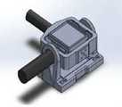
6 is a photograph showing a prototype to which a dynamic balance maintaining method according to the present invention is applied.
이하 첨부된 도면을 참조로 본 발명의 바람직한 실시예를 상세히 설명하기로 한다. 이에 앞서, 본 명세서 및 청구범위에 사용된 용어나 단어는 통상적이거나 사전적인 의미로 한정해서 해석되어서는 아니되며, 발명자는 그 자신의 발명을 가장 최선의 방법으로 설명하기 위해 용어의 개념을 적절하게 정의할 수 있다는 원칙에 입각하여 본 발명의 기술적 사상에 부합하는 의미와 개념으로 해석되어야만 한다. 따라서, 본 명세서에 기재된 실시예와 도면에 도시된 구성은 본 발명의 가장 바람직한 일 실시예에 불과할 뿐이고 본 발명의 기술적 사상을 모두 대변하는 것은 아니므로, 본 출원시점에 있어서 이들을 대체할 수 있는 다양한 균등물과 변형예들이 있을 수 있음을 이해하여야 한다.Hereinafter, preferred embodiments of the present invention will be described in detail with reference to the accompanying drawings. Prior to this, terms and words used in the present specification and claims should not be construed as limited to ordinary or dictionary terms, and the inventor should appropriately interpret the concepts of the terms appropriately It should be interpreted in accordance with the meaning and concept consistent with the technical idea of the present invention based on the principle that it can be defined. Therefore, the embodiments described in this specification and the configurations shown in the drawings are merely the most preferred embodiments of the present invention and do not represent all the technical ideas of the present invention. Therefore, It is to be understood that equivalents and modifications are possible.
먼저 동적 평형(Dynamic Balancing)이란, 플랫폼(Platform) 위에 놓여있는 사물에 작용하는 힘이 항상 플랫폼에 항상 수직한 방향으로 작용하도록 플랫폼의 경사각을 조정하는 것으로 도 4는 제어 전(왼쪽)과 제어 후(오른쪽)에 대하여 도시한 도면으로 플랫폼의 수평가속도가 항상 영(0)이 되도록 하는 것이다.First, dynamic balancing means adjusting the inclination angle of the platform so that the force acting on an object placed on the platform always acts in a direction perpendicular to the platform. (Right), the horizontal acceleration of the platform is always zero (0).
이때 플랫폼(Platform)이 임의의 가속도를 가질 때 동적 평형(Dynamic Balancing)을 이루기 위해서는 플랫폼 평면이 가속도에 수직을 유지하도록 플랫폼의 2-방향 회전각을 조정하여야 한다.In order to achieve dynamic balancing when the platform has arbitrary acceleration, the two-direction rotation angle of the platform should be adjusted so that the platform plane is perpendicular to the acceleration.
도 1은 본 발명에 따른 플랫폼의 동적 평형 유지를 위한 짐벌 기구를 도시한 도면이다.1 is a view showing a gimbals mechanism for maintaining dynamic balance of a platform according to the present invention.
도 1에 도시된 바와 같이 본 발명에 따른 동적 평형 유지를 위한 로봇은 피치 방향 및 롤 방향으로 독립적으로 회전 가능한 짐벌 기구(1)와, 짐벌 기구(1)의 피치 방향 및 롤 방향의 자세 변화 또는 움직임 중의 적어도 하나를 감지하기 위한 센서(도시되지 않음)와, 센서의 출력에 기초하여 짐벌 기구의 힘의 방향이 짐벌 기구의 표면에 수직인 성분만 존재하도록 하는 짐벌 기구의 자세 목표에 관한 정보를 산정하는 제어부(도시되지 않음)와, 제어부의 산정에 기초하여 짐벌 기구의 자세 변화 및 움직임을 발생시키는 액추에이터(도시되지 않음)가 포함된다.1, the robot for dynamic balance holding according to the present invention includes a gimbal mechanism 1 capable of independently rotating in a pitch direction and a roll direction, and a gimbal mechanism 1 for changing the attitude of the gimbal mechanism 1 in the pitch direction and the roll direction, (Not shown) for sensing at least one of the motions of the gimbals mechanism, and information about the posture target of the gimbals mechanism that causes the direction of the force of the gimbals mechanism to exist only on the surface of the gimbals mechanism based on the output of the sensor And an actuator (not shown) for generating a posture change and a movement of the gimbal mechanism based on the estimation of the control unit.
짐벌 기구(1)는 페이로드가 놓여 질 수 있는 상부 표면을 구비하는 플랫폼(10)과, 플랫폼(10)을 제1 회전축(21)에 대하여 회전가능하게 고정시키는 프레임(20)과, 프레임(20)을 제1 회전축(21)과 직교하는 제2 회전축(31)에 대하여 회전 가능하게 고정시키는 베이스(30)를 포함한다. 여기서 제2 회전축(31)은 베이스(30)와, 이 베이스(10) 기준 피치 방향으로 구동되는 피치 짐벌이며, 제1 회전축(21)은 피치 짐벌 내부에 장치되며 롤 방향으로 구동되는 롤 짐벌이다.The gimbal mechanism 1 includes a
센서는 짐벌 기구(10)의 다양한 위치에 구비될 수 있는데 다음에서 설명할 [실시 예 1]에서의 센서는 베이스에 설치되며, 이 베이스에 설치된 센서는 베이스 좌표계와 평행인 3-축 가속도계이다. 그리고 [실시예 2]에서의 센서는 프레임에 설치되며, 이 프레임에 설치된 센서는 프레임 좌표계와 평행인 3-축 가속도계이다. 마지막으로 [실시예 3]에서의 센서는 베이스와, 프레임에 각각 설치되는 2-축 가속도계인 것이다. 액추에이터는 모터에 의해 구동되고, 제어부는 컴퓨터를 이용한 디지털 제어를 적용한다.The sensor can be provided at various positions of the
도 2는 본 발명에 따른 플랫폼의 동적 평형 유지 방법을 도시한 순서도이며, 도 3은 본 발명에 따른 플랫폼의 동적 평형 유지 방법을 이용한 로봇의 제어 방법을 도시한 순서도이다.FIG. 2 is a flowchart illustrating a method of maintaining a dynamic balance of a platform according to the present invention, and FIG. 3 is a flowchart illustrating a method of controlling a robot using a dynamic balance holding method according to the present invention.
도 2에 도시된 바와 같이 본 발명의 플랫폼의 동적 평형 유지 방법은 먼저 플랫폼 상에 페이로드(payload)가 놓여진 상태에 따라 발생하는 플랫폼의 자세 변화 또는 플랫폼의 움직임에 대한 정보 중 적어도 하나의 정보를 포함하는 입력 데이터를 수신한다(S110).As shown in FIG. 2, the method for maintaining dynamic balance of a platform of the present invention includes at least one of information about a change in a posture of a platform or a movement of a platform, which occurs according to a state in which a payload is placed on the platform (S110).
그리고 단계 (S110)에서 수신된 입력 데이터에 기초하여, 상기 페이로드에 의하여 상기 플랫폼에 인가되는 힘의 방향이 플랫폼의 표면에 수직인 성분만 존재하도록 하는 플랫폼의 자세 목표에 관한 정보를 산정한다(S120).Then, on the basis of the input data received in step S110, information about the posture target of the platform is determined such that the direction of the force applied to the platform by the payload exists only in the component perpendicular to the surface of the platform S120).
도 3에 따른 본 발명의 플랫폼의 동적 평형 유지 방법을 이용한 로봇의 제어 방법은, 플랫폼 상에 페이로드(payload)가 놓여진 상태에 따라 발생하는 플랫폼의 자세 변화 또는 플랫폼의 움직임에 대한 정보 중 적어도 하나의 정보를 포함하는 입력 데이터를 검출한다(S210).The method for controlling a robot using the dynamic balance holding method of the present invention according to the present invention as shown in FIG. 3 is a method for controlling a robot using at least one of information about a posture change of a platform or a movement of a platform that occurs according to a state where a payload is placed on a platform (Step S210).
그리고 단계 (S210)에서 수신된 입력 데이터에 기초하여, 상기 페이로드에 의하여 상기 플랫폼에 인가되는 힘의 방향이 플랫폼의 표면에 수직인 성분만 존재하도록 하는 플랫폼의 자세 목표에 관한 정보를 산정한다(S220)Then, on the basis of the input data received in step S210, information on the posture target of the platform is determined such that the direction of the force applied to the platform by the payload exists only in the component perpendicular to the surface of the platform S220)
마지막으로 단계 (S220))에서 산정된 플랫폼의 자세 목표에 관한 정보에 기초하여 플랫폼의 자세 변화 및 움직임 중의 적어도 하나를 발생시킨다(S230).Finally, at step S230, at least one of the posture change and the movement of the platform is generated based on the information about the posture target of the platform calculated in step S220.
이때 본 발명에서 플랫폼(10)의 동적 평형 유지 제어를 위하여 가속도계를 이용하는데 본 발명에서는 서로 다른 실시예를 이용하였다. 앞에서 설명한 바와 같이 [제1 실시예]에서는 베이스(30)에 베이스 좌표계와 평행으로 3-축 가속도계를 설치하고, [제2 실시예]에서는 프레임(20)에 롤 짐벌 좌표계와 평행으로 3-축 가속도계를 설치하였으며, [제3 실시예]에서는 베이스(30)과 프레임(20)에 각각 2-축 가속도계를 설치하여 입력값을 얻어낸다. At this time, in the present invention, an accelerometer is used for dynamic balance maintaining control of the
[실시 예 1][Example 1]
베이스(30)에 베이스 좌표계와 평행으로 3축 가속도계를 설치하는 경우,When a three-axis accelerometer is installed on the
(1) 베이스 좌표계와 내부(롤) 짐벌 좌표계의 간의 관계(1) Relationship between the base coordinate system and the inner (roll) gimbals coordinate system
피치각이 θ , 롤각이 φ인 경우 When the pitch angle is? And the roll angle is?

(2) 베이스(30)에 설치된 가속도계가 측정한 가속도

(3) 내부(롤) 짐벌에서의 가속도는,(3) The acceleration in the inner (roll)

(4) 동적 평형(Dynamic Balancing)을 위해서는 내부(롤) 짐벌의 x, y-축 방향 가속도가 항상 영(0)이 되어야 하므로 조건 a′=b′=0을 만족해야 되며, 이 조건을 만족하는 피치각 θp와 롤각인 φr 을 구한다.(4) For dynamic balancing, the x, y-axis acceleration of the inner (roll) gimbals must always be zero, so the condition a '= b' = 0 must be satisfied. The pitch angle?P and the roll angle?R are obtained.

따라서 동적 평형 조건에서Therefore,

가 된다..
여기 [실시 예 1]은 베이스(30)에 가속도계를 장착하고 측정된 가속도계 신호를 이용하여 동적 평형을 이루는 각 짐벌의 회전각을 계산한 경우이다. 따라서 각 회전각의 오차, 회전축의 직교 오차 등이 베이스(30)에 가속도계가 장착되어 있으므로 있을 경우 오차가 발생할 수 있다.Here, [Embodiment 1] is a case in which an accelerometer is mounted on the
그리고 피치각


또한 앞에서 계산된 피치각 θp , 롤각 φr 위치는 각 샘플링 순간 각 김발의 위치명령이며, 각 김발 회전각을 측정하는 엔코더 신호를 피드백(Feedback)하여 제어를 수행한다.In addition, the pitch angle θp and roll angle φr positions calculated above are the position commands of the gimbal at each sampling instant, and feedback is performed by feedback of the encoder signal measuring the gimbal rotation angle.
[실시 예 2][Example 2]
내부(롤) 짐벌(20)에 내부(롤) 짐벌 좌표계와 평행으로 3축 가속도계를 설치하는 경우,When a three-axis accelerometer is installed in the inner (roll) gimbals 20 in parallel with the inner (roll) gimbals coordinate system,
앞서 [실시 예 1]에서와 같이 베이스(10)에 가속도계를 장착하는 경우 실제 내부(롤) 짐벌(30)의 가속도를 알 수 없으므로 동적 평형이 이루어졌는지 알 수 없다. 따라서 [실시 예 2]에서는 내부(롤) 짐벌(30)에 직접 가속도계를 설치한다.When the accelerometer is mounted on the base 10 as in the first embodiment, it is impossible to know the dynamic acceleration because the acceleration of the inner (roll) gimbals 30 is unknown. Therefore, in [Embodiment 2], an accelerometer is installed directly on the inner (roll) gimbals 30.
(1) 내부(롤) 짐벌(20)에 설치된 가속도계가 측정한 가속도

(2) 이 순간 피치각이 θk, 롤각이 φk이라면, 이 가속도로부터 베이스 좌표계에서의 가속도 계산(2) If the instantaneous pitch angle is θk and the roll angle is φk , the acceleration in the base coordinate system is calculated from this acceleration

(3) 이 베이스 좌표계로 나타낸 가속도를 이용하여 내부(롤) 짐벌의 동적 평형을 이루는 피치각(3) The pitch angle that forms the dynamic equilibrium of the inner (roll) gimbals using the acceleration represented by this base coordinate system
θp, 롤각인φr 을 구한다.θp , and the roll angle φr .
우선 피치각 θp, 롤각 φr 회전한 내부(롤) 짐벌 좌표계와 베이스 좌표계의 관계는First, the relation between the inner (roll) gimbals coordinate system rotated with the pitch angle θp , the roll angle φr and the base coordinate system


를 이용하면,In this case,

여기서,here,

로 정의하고, 이를 이용하여 식을 다시 쓰면,If we rewrite the equation using this,

따라서, 동적 평형을 이루기 위해서는 x-축, y-축 가속도가 영이 되어야 한다.Therefore, to achieve dynamic equilibrium, the x- and y-axis accelerations must be zero.
즉,In other words,

이 식으로부터From this equation

따라서 동적 평형을 이루기 위한 외부(피치)짐벌과 내부(롤)김발의 오차각은Therefore, the error angle between the external (pitch) gimbal and the internal (roll)

여기서 θek , φek는 샘플링 순간 각 짐벌의 위치오차이다.Where θek , φek is the position error of each gimbal at the instant of sampling.
[실시 예 3][Example 3]
외부(피치) 짐벌(30)과 내부(롤) 짐벌(20)에 각각 2축 가속도계를 설치하는 경우이며, [실시 예 3]의 개념은 다음과 같다.Axis accelerometer is provided in the outer (pitch)
첫째, 외부(피치) 짐벌에 설치된 가속도계의 xp-축 방향 가속도가 영이 되도록 외부(피치) 짐벌을 피치방향으로 회전하여 제어한다.First, the external (pitch) gimbals are controlled to rotate in the pitch direction so that the acceleration in the xp -axis of the accelerometer installed on the external (pitch) gimbals is zero.
이는 외부(피치) 짐벌의의 xp-축과 내부(롤) 짐벌의 xr-축은 일치하거나 평행하므로, 외부(피치) 짐벌의 xp-축 가속도가 영이면 내부(롤) 짐벌 xr-축 가속도는 영이 된다. ( 단,xp-축과 xr-축의 평행도 오차는 xp-축 가속도가 영이더라도 xr-축의 가속도가 존재하며, 또한 xp-축과 xr-축간의 거리는 외부(피치) 짐벌의 각가속도와 각속도에 의해 xr-축 방향 가속도가 존재하게 된다. 따라서 외부(피치) 짐벌의 xp-축과 내부(롤) 짐벌의 xr-축을 일치시키는 것이 최선이며, 불가피 할 경우 축간 거리를 최소화 하는 것이 바람직하다.)This external (pitch) of the gimbal xp of the - so-axis match or parallel, external (pitch) of the gimbal of xp - - of the shaft and the inside (rolls) gimbal xr is the axial acceleration is zero internal (rolls) gimbal xr - The axis acceleration becomes zero. (However, the parallelism error between the xp - axis and the xr - axis is the acceleration of the xr - axis even if the xp - axis acceleration is zero, and the distance between the xp - axis and the xr - the axial acceleration will exist therefore outside (pitch) xp of the gimbals - - xr by an angular acceleration and angular velocity. shaft and the inside (roll), the gimbals of the xr -, and it is best to match the axis, the case may be inevitable center distance It is desirable to minimize it.)
둘째, 내부(롤) 짐벌에 설치된 가속도계의 yr-축 방향 가속도가 영이 되도록 내부(롤) 짐벌을 롤방향으로 회전하여 제어한다.Second, the inner (roll), yr of the accelerometer is installed suit load - to rotate the inner (rolls) with roll gimbals direction control so that the axial acceleration zero.
셋째, 결과적으로 첫째와 둘째의 제어에 의해 내부(롤) 짐벌의 xr-축과 yr-축 가속도가 영이 되어 동적 평형을 가능케 한다.Third, as a result, the first and under the control of the second xr inside (roll), the gimbal-axis and the yr - is the zero-axis acceleration allows the dynamic balance.
[실시예 3]의 개념을 증명하면 다음과 같다.The concept of [Embodiment 3] is proved as follows.
베이스(10)에 설치된 가속도계가 측정한 가속도가

이 때의 피치각이 θp라면, 내부(피치) 짐벌 가속도는If the pitch angle at this time is?P , the internal (pitch) gimbal acceleration is

내부(피치) 짐벌의 xp-축 가속도는The xp - axis acceleration of the inner (pitch) gimbals is

이므로, 피치각을 다음의 θp로 하면Therefore, assuming that the pitch angle is the following?P

이고,ego,


즉, 외부(피치) 짐벌 xp-축 가속도는 영이 된다.That is, the external (pitch) gimbals xp - axis acceleration becomes zero.
그리고, 피치각을 위의 θp로 회전시키고, 이때 내부(롤) 짐벌의 롤각이φr 이라면, 내부(롤) 짐벌의 가속도는Then, if the pitch angle is rotated at θp above and the roll angle of the inner (roll) gimbals is φr, then the acceleration of the inner (roll) gimbals is

이고, 내부(롤) 짐벌의 xr-축 가속도는 앞에서 피치축 회전으로 이미 영이며, yr-축 가속도는 다음과 같으므로, The xr - axis acceleration of the inner (roll) gimbals is already zero with the pitch axis rotation in the front, and the yr - axis acceleration is

내부(롤) 짐벌을 다음의 φr 각 만큼 회전시키면When the inner (roll) gimbals are rotated by the following angle φr

내부(롤) 짐벌의 가속도는The acceleration of the inner (roll)

이므로, 내부(롤) 짐벌의 동적 평형이 완성된다., The dynamic equilibrium of the inner (roll) gimbals is completed.
즉 [실시 예 3]의 동적 평형 제어인 외부(피치) 짐벌과 내부(롤) 짐벌의 제어는 다음과 같다.That is, the control of the external (pitch) gimbal and the internal (roll) gimbals, which is the dynamic equilibrium control of [Example 3], is as follows.
(1) 외부(피치) 짐벌 제어(1) External (pitch) gimbal control
만일 외부(피치) 짐벌에 설치된 가속도계에서 측정된 가속도가

이 때의 피치각이 θ라면, 피치각이θp 일 때 외부(피치) 짐벌의 가속도

따라서 외부(피치) 짐벌의 xp-축 가속도를 영으로 하기 위한 피치회전각은Therefore, the pitch rotation angle to zero the xp - axis acceleration of the external (pitch) gimbals is

또는 현 회전각 기준 추가로 회전이 필요한 오차각도는Or an error angle that requires rotation in addition to the current rotation angle reference

만일 동적 평형(Dynamic Balancing)을 하는 동안이라면


(2) 내부(롤) 짐벌 제어(2) Internal (roll) gimbal control
만일 내부(롤) 짐벌에 설치된 가속도계에서 측정된 가속도가

이 때 롤각이 φ라면, 롤각이 φr일 때 내부(롤) 짐벌의 가속도

따라서 내부(롤) 짐벌의 yr-축 가속도를 영으로 하기 위한 롤회전각은Therefore, the roll rotation angle to zero the yr - axis acceleration of the inner (roll) gimbals is

또는 현 회전각 기준 추가로 회전이 필요한 오차각도는Or an error angle that requires rotation in addition to the current rotation angle reference

만일 동적 평형(Dynamic Balancing)을 하는 동안이라면


도 5는 본 발명에 다른 플랫폼의 동적 평형 유지 방법이 적용된 플랫폼의 동적 평형 유지 장치를 3D로 도시한 도면이고, 도 6은 본 발명에 따른 플랫폼의 동적 평형 유지 방법이 적용된 프로토타입을 나타낸 사진으로 물체에는 플랫폼과 수직 방향의 힘만 존재하고, 측면 방향의 힘이 없으므로 물체는 넘어지거나 미끄러지지 않고 항상 플랫폼과 접촉을 유지하게 되며, 정지한 상태일 경우 플랫폼은 항상 수평을 유지하다. 이와 같은 본 발명 장치의 적용은 화물 운반, 환자이송, 카메라 안정화에 이용될 수 있는데 예를 들면 적재된 물건이 떨어지지 않도록 화물적재 부분에 성능을 부여할 수 있고, 구급차가 이동하는 중에도 환자가 떨어지지 않는 침대, 승객이 전후좌우로 흔들리지 않는 다양한 이송수단의 의자, 선박이나 드론 등에 장치되어 수평을 유지하는 카메라 장착대 등에 적용 가능하며, 나열된 예로서 한정하는 것은 아니며 다양한 분야에 적용될 수 있다.FIG. 5 is a diagram showing a dynamic balance holding apparatus of a platform to which a dynamic balance holding method of a platform according to the present invention is applied, and FIG. 6 is a photograph showing a prototype to which a dynamic balance holding method according to the present invention is applied. The object has only force in the direction perpendicular to the platform. Since there is no force in the lateral direction, the object does not fall or slip and always maintains contact with the platform. In the stopped state, the platform is always horizontal. Such an application of the present invention can be used for cargo transportation, patient transportation, and camera stabilization. For example, performance can be imparted to a cargo loading portion so that a loaded object does not fall off, and even when an ambulance is moving, A bed, a chair of various conveying means which passengers do not sway back and forth, and a camera mounting stand which is installed on a ship or a drone and maintains a horizontal position, and the present invention can be applied to various fields.
이상과 같이, 본 발명은 비록 한정된 실시예와 도면에 의해 설명되었으나, 본 발명은 이것에 의해 한정되지 않으며 본 발명이 속하는 기술분야에서 통상의 지식을 가진 자에 의해 본 발명의 기술사상과 아래에 기재될 특허청구범위의 균등범위 내에서 다양한 수정 및 변형이 가능함은 물론이다.While the present invention has been particularly shown and described with reference to exemplary embodiments thereof, it is to be understood that the invention is not limited to the disclosed exemplary embodiments. It will be understood that various modifications and changes may be made without departing from the scope of the appended claims.
1: 짐벌 기구
10: 플랫폼
20: 프레임
21: 제1 회전축(롤 짐벌)
30: 베이스
31: 제2 회전축(피치 짐벌)
1: gimbal mechanism
10: Platform
20: frame
21: First rotary shaft (roll gimbals)
30: Base
31: Second rotary shaft (pitch gimbals)
Claims (8)
Translated fromKorean(a) 플랫폼 상에 페이로드(payload)가 놓여진 상태로 상기 플랫폼이 직선 가속도 운동을 함에 따라 발생하는 플랫폼의 자세 변화 또는 플랫폼의 움직임에 대한 정보 중 적어도 하나의 정보를 포함하는 입력 데이터를 수신하는 단계; 및
(b) 상기 단계 (a)에서 수신된 입력 데이터에 기초하여, 상기 플랫폼이 직선 가속도 운동을 하는 동안 상기 페이로드에 의하여 상기 플랫폼에 인가되는 힘의 방향이 플랫폼의 표면에 수직인 성분만 존재하도록 하는 플랫폼의 자세 목표에 관한 정보를 산정하는 단계
를 포함하는 플랫폼의 동적 평형 유지 방법.CLAIMS 1. A method for maintaining dynamic balance of a platform,
(a) receiving input data including at least one of information of a posture change of a platform or a movement of a platform that occurs as the platform performs a linear acceleration movement in a state where a payload is placed on the platform step; And
(b) determining, based on the input data received in the step (a), that the direction of the force applied to the platform by the payload while the platform is performing the linear acceleration movement is only an element perpendicular to the surface of the platform A step of calculating information on a posture target of the platform
The method comprising the steps of:
(a) 플랫폼 상에 페이로드(payload)가 놓여진 상태로 상기 플랫폼에 직선 가속도 운동을 함에 따라 발생하는 플랫폼의 자세 변화 또는 플랫폼의 움직임에 대한 정보 중 적어도 하나의 정보를 포함하는 입력 데이터를 검출하는 단계;
(b) 상기 단계 (a)에서 수신된 입력 데이터에 기초하여, 상기 플랫폼이 직선 가속도 운동을 하는 동안 상기 페이로드에 의하여 상기 플랫폼에 인가되는 힘의 방향이 플랫폼의 표면에 수직인 성분만 존재하도록 하는 플랫폼의 자세 목표에 관한 정보를 산정하는 단계; 및
(c) 상기 단계 (b)에서 산정된 플랫폼의 자세 목표에 관한 정보에 기초하여 플랫폼의 자세 변화 및 움직임 중의 적어도 하나를 발생시키는 단계
를 포함하는 로봇의 제어 방법.A method of controlling a robot using a method for maintaining dynamic balance of a platform,
(a) detecting input data including at least one piece of information on a platform attitude change or a platform motion occurring as a linear acceleration movement is performed on the platform in a state where a payload is placed on the platform step;
(b) determining, based on the input data received in the step (a), that the direction of the force applied to the platform by the payload while the platform is performing the linear acceleration movement is only an element perpendicular to the surface of the platform Estimating information about a posture target of the platform; And
(c) generating at least one of a posture change and a movement of the platform based on the information about the posture target of the platform calculated in the step (b)
And a controller for controlling the robot.
피치 방향 및 롤 방향으로 독립적으로 회전 가능하도록 상기 플랫폼과 연결되는 짐벌 기구;
상기 플랫폼의 피치 방향 및 롤 방향의 자세 변화 또는 움직임 중의 적어도 하나를 감지하기 위한 센서;
상기 센서의 출력에 기초하여 상기 플랫폼이 직선 가속도 운도을 하는 동안 상기 페이로드에 의하여 상기 플랫폼에 인가되는 힘의 방향이 플랫폼의 표면에 수직인 성분만 존재하도록 하는 짐벌 기구의 자세 목표에 관한 정보를 산정하는 제어부; 및
상기 제어부의 산정에 기초하여 짐벌 기구의 자세 변화 및 움직임을 발생시키는 액추에이터
를 포함하는 로봇.A platform having a top surface over which the payload can be placed;
A gimbal mechanism connected to the platform so as to be independently rotatable in a pitch direction and a roll direction;
A sensor for sensing at least one of an attitude change and a movement in a pitch direction and a roll direction of the platform;
Estimating information about a posture target of the gimbal mechanism such that the direction of the force applied to the platform by the payload is perpendicular to the surface of the platform while the platform is performing a linear acceleration run based on the output of the sensor ; And
An actuator for generating a posture change and a motion of the gimbal mechanism based on the calculation of the control unit;
.
상기 짐벌 기구는
상기 플랫폼을 제1 회전축에 대하여 회전 가능하게 고정시키는 프레임; 및
상기 프레임을 상기 제1 회전축과 직교하는 제2 회전축에 대하여 회전 가능하게 고정시키는 베이스
를 포함하는 것을 특징으로 하는 로봇.The method of claim 3,
The gimbal mechanism
A frame rotatably fixing the platform with respect to the first rotation axis; And
Wherein the frame is rotatably fixed to a second rotation axis orthogonal to the first rotation axis,
And a robot.
상기 센서는 베이스에 설치되며, 이 베이스에 설치된 센서는 베이스 좌표계와 평행인 3-축 가속도계인 것
을 특징으로 하는 로봇.The method of claim 3,
The sensor is installed on the base, and the sensor installed on the base is a three-axis accelerometer parallel to the base coordinate system
.
상기 센서는 프레임에 설치되며, 이 프레임에 설치된 센서는 프레임 좌표계와 평행인 3-축 가속도계인 것
을 특징으로 하는 로봇.The method of claim 3,
The sensor is installed in a frame, and the sensor installed in the frame is a three-axis accelerometer parallel to the frame coordinate system
.
상기 센서는 베이스와, 프레임에 각각 설치되는 2-축 가속도계인 것
을 특징으로 하는 로봇.The method of claim 3,
The sensor is a two-axis accelerometer mounted on a base and a frame, respectively
.
Priority Applications (1)
| Application Number | Priority Date | Filing Date | Title |
|---|---|---|---|
| KR1020170162237AKR102005405B1 (en) | 2017-11-29 | 2017-11-29 | Dynamic balancing maintenance method of platform, robot and robot control method using it |
Applications Claiming Priority (1)
| Application Number | Priority Date | Filing Date | Title |
|---|---|---|---|
| KR1020170162237AKR102005405B1 (en) | 2017-11-29 | 2017-11-29 | Dynamic balancing maintenance method of platform, robot and robot control method using it |
Publications (2)
| Publication Number | Publication Date |
|---|---|
| KR20190063276A KR20190063276A (en) | 2019-06-07 |
| KR102005405B1true KR102005405B1 (en) | 2019-07-30 |
Family
ID=66850243
Family Applications (1)
| Application Number | Title | Priority Date | Filing Date |
|---|---|---|---|
| KR1020170162237AExpired - Fee RelatedKR102005405B1 (en) | 2017-11-29 | 2017-11-29 | Dynamic balancing maintenance method of platform, robot and robot control method using it |
Country Status (1)
| Country | Link |
|---|---|
| KR (1) | KR102005405B1 (en) |
Families Citing this family (2)
| Publication number | Priority date | Publication date | Assignee | Title |
|---|---|---|---|---|
| KR102586021B1 (en)* | 2021-12-14 | 2023-10-06 | 주식회사 지피오 | Food spill prevention apparatus in moving service robot |
| CN118641101B (en)* | 2024-08-17 | 2024-12-13 | 苏州工业职业技术学院 | Balance testing device and system of automatic inspection robot |
Citations (3)
| Publication number | Priority date | Publication date | Assignee | Title |
|---|---|---|---|---|
| KR100685339B1 (en) | 2004-11-11 | 2007-02-26 | 가부시키가이샤 히타치세이사쿠쇼 | Mobile robot |
| JP2015134613A (en) | 2008-11-06 | 2015-07-27 | セグウェイ・インコーポレイテッド | Device and method for controlling dynamic self-balance vehicle |
| KR101684940B1 (en) | 2015-12-29 | 2016-12-12 | 가천대학교 산학협력단 | Stabilized stretcher apparatus and Stabilization method for stretcher using the same |
Family Cites Families (2)
| Publication number | Priority date | Publication date | Assignee | Title |
|---|---|---|---|---|
| JPS5880726A (en) | 1981-11-06 | 1983-05-14 | Nec Corp | Input device of information written in japanese |
| JP2011523903A (en)* | 2008-05-21 | 2011-08-25 | ジョージア テック リサーチ コーポレイション | Force balance mobile robot system |
- 2017
- 2017-11-29KRKR1020170162237Apatent/KR102005405B1/ennot_activeExpired - Fee Related
Patent Citations (3)
| Publication number | Priority date | Publication date | Assignee | Title |
|---|---|---|---|---|
| KR100685339B1 (en) | 2004-11-11 | 2007-02-26 | 가부시키가이샤 히타치세이사쿠쇼 | Mobile robot |
| JP2015134613A (en) | 2008-11-06 | 2015-07-27 | セグウェイ・インコーポレイテッド | Device and method for controlling dynamic self-balance vehicle |
| KR101684940B1 (en) | 2015-12-29 | 2016-12-12 | 가천대학교 산학협력단 | Stabilized stretcher apparatus and Stabilization method for stretcher using the same |
Non-Patent Citations (1)
| Title |
|---|
| Erick Moya et al. "Study on the Inertial Stabilization of a Payload by Center of Gravity Displacement", Proceedings of the 2016 IEEE/SICE International Symposium on System Integration, pp.266-271(2016* |
Also Published As
| Publication number | Publication date |
|---|---|
| KR20190063276A (en) | 2019-06-07 |
Similar Documents
| Publication | Publication Date | Title |
|---|---|---|
| US20100057319A1 (en) | Inverted two-wheel guided vehicle and control method therefor | |
| JP2009234524A (en) | Transporting device and drive mechanism | |
| JP5724855B2 (en) | Inverted moving body and angular velocity sensor output value correction method | |
| CN106527459B (en) | Stable platform and control method thereof | |
| WO2008032587A1 (en) | Vehicle | |
| JP6191580B2 (en) | Sensor calibration method for moving objects | |
| CN107352038A (en) | The control method of head and the control system of head | |
| US20100295972A1 (en) | Ocular Motor Controller Using Principle of Vestibulo-ocular Reflex | |
| US20210107146A1 (en) | Gimbal control method and gimbal | |
| JP6604175B2 (en) | Pitch angular velocity correction value calculation device, attitude angle calculation device, and pitch angular velocity correction value calculation method | |
| KR102005405B1 (en) | Dynamic balancing maintenance method of platform, robot and robot control method using it | |
| WO2018191963A1 (en) | Remote control, camera mount, and camera mount control method, device, and system | |
| CN104035445A (en) | Remote control device, control system and control method | |
| US11230019B2 (en) | Posture angle calculation apparatus, moving apparatus, posture angle calculation method, and program | |
| CN110869283A (en) | Control method and device of cloud deck, cloud deck system and unmanned aerial vehicle | |
| JP2010143238A (en) | Control device for underwater moving body | |
| US10981617B2 (en) | Inverted pendulum type vehicle | |
| JP2017520136A (en) | Remote control device, control system, and control method | |
| JP2010247551A (en) | Irradiation direction control device | |
| JP2017188743A (en) | Camera calibration apparatus and camera calibration method | |
| JP7455558B2 (en) | Imaging device and its spatial stabilization method | |
| JP6454857B2 (en) | Posture detection apparatus and posture detection method | |
| JP3772806B2 (en) | Magnetic orientation detection method and magnetic orientation detection method | |
| US11378960B2 (en) | Mobile entity | |
| JPH11142428A (en) | Servo platform for accelerometer, and flight controller |
Legal Events
| Date | Code | Title | Description |
|---|---|---|---|
| A201 | Request for examination | ||
| PA0109 | Patent application | St.27 status event code:A-0-1-A10-A12-nap-PA0109 | |
| PA0201 | Request for examination | St.27 status event code:A-1-2-D10-D11-exm-PA0201 | |
| D13-X000 | Search requested | St.27 status event code:A-1-2-D10-D13-srh-X000 | |
| D14-X000 | Search report completed | St.27 status event code:A-1-2-D10-D14-srh-X000 | |
| E902 | Notification of reason for refusal | ||
| PE0902 | Notice of grounds for rejection | St.27 status event code:A-1-2-D10-D21-exm-PE0902 | |
| T11-X000 | Administrative time limit extension requested | St.27 status event code:U-3-3-T10-T11-oth-X000 | |
| T11-X000 | Administrative time limit extension requested | St.27 status event code:U-3-3-T10-T11-oth-X000 | |
| P11-X000 | Amendment of application requested | St.27 status event code:A-2-2-P10-P11-nap-X000 | |
| P13-X000 | Application amended | St.27 status event code:A-2-2-P10-P13-nap-X000 | |
| PG1501 | Laying open of application | St.27 status event code:A-1-1-Q10-Q12-nap-PG1501 | |
| E701 | Decision to grant or registration of patent right | ||
| PE0701 | Decision of registration | St.27 status event code:A-1-2-D10-D22-exm-PE0701 | |
| GRNT | Written decision to grant | ||
| PR0701 | Registration of establishment | St.27 status event code:A-2-4-F10-F11-exm-PR0701 | |
| PR1002 | Payment of registration fee | St.27 status event code:A-2-2-U10-U11-oth-PR1002 Fee payment year number:1 | |
| PG1601 | Publication of registration | St.27 status event code:A-4-4-Q10-Q13-nap-PG1601 | |
| R18-X000 | Changes to party contact information recorded | St.27 status event code:A-5-5-R10-R18-oth-X000 | |
| PR1001 | Payment of annual fee | St.27 status event code:A-4-4-U10-U11-oth-PR1001 Fee payment year number:4 | |
| PR1001 | Payment of annual fee | St.27 status event code:A-4-4-U10-U11-oth-PR1001 Fee payment year number:5 | |
| R18-X000 | Changes to party contact information recorded | St.27 status event code:A-5-5-R10-R18-oth-X000 | |
| R18-X000 | Changes to party contact information recorded | St.27 status event code:A-5-5-R10-R18-oth-X000 | |
| PC1903 | Unpaid annual fee | St.27 status event code:A-4-4-U10-U13-oth-PC1903 Not in force date:20240725 Payment event data comment text:Termination Category : DEFAULT_OF_REGISTRATION_FEE | |
| R18-X000 | Changes to party contact information recorded | St.27 status event code:A-5-5-R10-R18-oth-X000 | |
| PC1903 | Unpaid annual fee | St.27 status event code:N-4-6-H10-H13-oth-PC1903 Ip right cessation event data comment text:Termination Category : DEFAULT_OF_REGISTRATION_FEE Not in force date:20240725 |