KR102001569B1 - Air pad for protection of machinery - Google Patents
Air pad for protection of machineryDownload PDFInfo
- Publication number
- KR102001569B1 KR102001569B1KR1020190022233AKR20190022233AKR102001569B1KR 102001569 B1KR102001569 B1KR 102001569B1KR 1020190022233 AKR1020190022233 AKR 1020190022233AKR 20190022233 AKR20190022233 AKR 20190022233AKR 102001569 B1KR102001569 B1KR 102001569B1
- Authority
- KR
- South Korea
- Prior art keywords
- tube member
- layer
- mechanical device
- pressure
- magnetic sheet
- Prior art date
- Legal status (The legal status is an assumption and is not a legal conclusion. Google has not performed a legal analysis and makes no representation as to the accuracy of the status listed.)
- Active
Links
- 239000000758substrateSubstances0.000claimsdescription20
- 229920000049Carbon (fiber)Polymers0.000claimsdescription15
- 239000004917carbon fiberSubstances0.000claimsdescription15
- VNWKTOKETHGBQD-UHFFFAOYSA-NmethaneChemical groupCVNWKTOKETHGBQD-UHFFFAOYSA-N0.000claimsdescription14
- 238000000034methodMethods0.000claimsdescription14
- 239000002131composite materialSubstances0.000claimsdescription11
- 238000002347injectionMethods0.000claimsdescription10
- 239000007924injectionSubstances0.000claimsdescription10
- 230000006378damageEffects0.000abstractdescription10
- 230000000116mitigating effectEffects0.000abstract1
- 238000004519manufacturing processMethods0.000description8
- 229910045601alloyInorganic materials0.000description4
- 239000000956alloySubstances0.000description4
- 238000005452bendingMethods0.000description4
- 239000002184metalSubstances0.000description4
- 239000000853adhesiveSubstances0.000description3
- 230000001070adhesive effectEffects0.000description3
- 239000000696magnetic materialSubstances0.000description3
- 230000001105regulatory effectEffects0.000description3
- 239000011230binding agentSubstances0.000description2
- 239000002134carbon nanofiberSubstances0.000description2
- 238000010276constructionMethods0.000description2
- 238000005516engineering processMethods0.000description2
- 238000007689inspectionMethods0.000description2
- 239000006247magnetic powderSubstances0.000description2
- 239000000463materialSubstances0.000description2
- 238000012986modificationMethods0.000description2
- 230000004048modificationEffects0.000description2
- 239000002245particleSubstances0.000description2
- 239000000843powderSubstances0.000description2
- 230000035939shockEffects0.000description2
- OKTJSMMVPCPJKN-UHFFFAOYSA-NCarbonChemical compound[C]OKTJSMMVPCPJKN-UHFFFAOYSA-N0.000description1
- 229910005347FeSiInorganic materials0.000description1
- 229910002796Si–AlInorganic materials0.000description1
- 229910008423Si—BInorganic materials0.000description1
- 229910008458Si—CrInorganic materials0.000description1
- 230000008859changeEffects0.000description1
- 230000006835compressionEffects0.000description1
- 238000007906compressionMethods0.000description1
- 230000008878couplingEffects0.000description1
- 238000010168coupling processMethods0.000description1
- 238000005859coupling reactionMethods0.000description1
- 230000006866deteriorationEffects0.000description1
- 230000009977dual effectEffects0.000description1
- 230000000694effectsEffects0.000description1
- 239000004744fabricSubstances0.000description1
- 239000000835fiberSubstances0.000description1
- 238000010030laminatingMethods0.000description1
- 238000003475laminationMethods0.000description1
- 239000000203mixtureSubstances0.000description1
- 238000000465mouldingMethods0.000description1
- 238000003825pressingMethods0.000description1
- 239000011347resinSubstances0.000description1
- 229920005989resinPolymers0.000description1
- 230000004044responseEffects0.000description1
- 239000002109single walled nanotubeSubstances0.000description1
- 239000013585weight reducing agentSubstances0.000description1
Images


Classifications
- F—MECHANICAL ENGINEERING; LIGHTING; HEATING; WEAPONS; BLASTING
- F16—ENGINEERING ELEMENTS AND UNITS; GENERAL MEASURES FOR PRODUCING AND MAINTAINING EFFECTIVE FUNCTIONING OF MACHINES OR INSTALLATIONS; THERMAL INSULATION IN GENERAL
- F16F—SPRINGS; SHOCK-ABSORBERS; MEANS FOR DAMPING VIBRATION
- F16F9/00—Springs, vibration-dampers, shock-absorbers, or similarly-constructed movement-dampers using a fluid or the equivalent as damping medium
- F16F9/02—Springs, vibration-dampers, shock-absorbers, or similarly-constructed movement-dampers using a fluid or the equivalent as damping medium using gas only or vacuum
- F16F9/04—Springs, vibration-dampers, shock-absorbers, or similarly-constructed movement-dampers using a fluid or the equivalent as damping medium using gas only or vacuum in a chamber with a flexible wall
- B—PERFORMING OPERATIONS; TRANSPORTING
- B25—HAND TOOLS; PORTABLE POWER-DRIVEN TOOLS; MANIPULATORS
- B25J—MANIPULATORS; CHAMBERS PROVIDED WITH MANIPULATION DEVICES
- B25J19/00—Accessories fitted to manipulators, e.g. for monitoring, for viewing; Safety devices combined with or specially adapted for use in connection with manipulators
- B25J19/0075—Means for protecting the manipulator from its environment or vice versa
- B—PERFORMING OPERATIONS; TRANSPORTING
- B25—HAND TOOLS; PORTABLE POWER-DRIVEN TOOLS; MANIPULATORS
- B25J—MANIPULATORS; CHAMBERS PROVIDED WITH MANIPULATION DEVICES
- B25J19/00—Accessories fitted to manipulators, e.g. for monitoring, for viewing; Safety devices combined with or specially adapted for use in connection with manipulators
- B25J19/06—Safety devices
- B25J19/063—Safety devices working only upon contact with an outside object
- F—MECHANICAL ENGINEERING; LIGHTING; HEATING; WEAPONS; BLASTING
- F16—ENGINEERING ELEMENTS AND UNITS; GENERAL MEASURES FOR PRODUCING AND MAINTAINING EFFECTIVE FUNCTIONING OF MACHINES OR INSTALLATIONS; THERMAL INSULATION IN GENERAL
- F16F—SPRINGS; SHOCK-ABSORBERS; MEANS FOR DAMPING VIBRATION
- F16F9/00—Springs, vibration-dampers, shock-absorbers, or similarly-constructed movement-dampers using a fluid or the equivalent as damping medium
- F16F9/32—Details
- F16F9/34—Special valve constructions; Shape or construction of throttling passages
- F—MECHANICAL ENGINEERING; LIGHTING; HEATING; WEAPONS; BLASTING
- F16—ENGINEERING ELEMENTS AND UNITS; GENERAL MEASURES FOR PRODUCING AND MAINTAINING EFFECTIVE FUNCTIONING OF MACHINES OR INSTALLATIONS; THERMAL INSULATION IN GENERAL
- F16P—SAFETY DEVICES IN GENERAL; SAFETY DEVICES FOR PRESSES
- F16P7/00—Emergency devices preventing damage to a machine or apparatus
Landscapes
- Engineering & Computer Science (AREA)
- General Engineering & Computer Science (AREA)
- Mechanical Engineering (AREA)
- Robotics (AREA)
- Manipulator (AREA)
Abstract
Translated fromKoreanDescription
Translated fromKorean본 발명은 장애물과의 충돌 시 충격을 충분히 완화할 수 있고 기계장치와 장애물의 쌍방 기계적 손상을 최소한으로 억제할 수 있는 기계장치 보호용 에어패드에 관한 것이다.The present invention relates to an air pad for protecting a mechanical device that can sufficiently mitigate an impact upon collision with an obstacle and can minimize mechanical damages of both the mechanical device and the obstacle.
현대 산업 사회는 기계화, 자동화 등으로 생산기술이 점점 발달하고 있다. 생산기술의 발전과 더불어 제조, 운반, 검사 또는 서비스에서 기계장치, 로봇 및 이들의 매니퓰레이터가 사람의 노동력을 대체하게 되어 활용분야가 점점 확대되고 있으며, 그 수요가 증가함에 따라 기계적 손상이나 장애물과의 충돌을 방지하기 위한 방안들이 다양하게 제안되고 있다.In modern industrial society, production technology is increasingly developed by mechanization and automation. With the development of production technology, the use of machinery, robots and their manipulators in manufac- turing, transportation, inspections or services has replaced human labor, and as the demand increases, Various methods for preventing collision have been proposed.
예를 들면, 출입문을 설치한 경우, 출입문 개방시 기계장치, 로봇 등이 정지하도록 하는 안전장치(인터록 장치, 안전 플러그)를 설치하는 방안, 위험구역 안으로 작업자가 접근할 경우 이를 센서가 감지하여 로봇이 정지하도록 방호장치를 설치하는 방안, 사용 중 비상상황 발생 시 스위치를 눌러 기계장치, 로봇 등의 위험 동작을 정지시키는 방안 등이 제안되고 있으나, 이와 같은 방안들은 기계장치, 로봇 등의 기계적 손상이나 장애물과의 충돌을 방지하기 위한 적극적인 대처방안은 되지 못하고 있다.For example, when a door is opened, a safety device (interlock device, safety plug) for stopping a mechanical device or a robot when the door is opened, a sensor for detecting a robot approaching the dangerous area, In the case of an emergency, there is proposed a method of stopping a dangerous operation such as a mechanical device or a robot by pressing a switch in the event of an emergency during use. It is not an active countermeasure to prevent collision with an obstacle.
한국공개특허 제10-2017-0026462호에는 복수의 소용량 보호 요소들을 제공하여 로봇 및 그의 매니퓰레이터를 보호하는 핸들링 장치를 위한 보호 방법 및 보호 디바이스가 개시되어 있다. 그러나, 이와 같은 보호 방법 및 보호 디바이스는 작은 크기의 복수의 보호요소를 결합시켜야 하므로 보호 디바이스의 결합구조가 복잡해지는 단점이 존재한다.Korean Patent Laid-Open No. 10-2017-0026462 discloses a protection method and a protection device for a handling device that protects a robot and its manipulator by providing a plurality of small-capacity protection elements. However, such a protection method and a protection device have to combine a plurality of protection elements of a small size, so that a coupling structure of the protection device becomes complicated.
본 발명의 목적은 장애물과의 충돌 시 충격을 충분히 완화할 수 있고 기계장치 및 장애물의 쌍방 기계적 손상을 최소한으로 억제할 수 있고, 장착이 용이한 기계장치 보호용 에어패드를 제공하는 것이다.It is an object of the present invention to provide an air pad for protecting a mechanical device which can sufficiently mitigate an impact upon collision with an obstacle and can suppress both mechanical damages of a mechanical device and an obstacle to a minimum and which is easy to mount.
본 발명의 다른 목적 및 장점들은 하기에 설명될 것이며, 본 발명의 실시예에 의해 알게 될 것이다. 또한, 본 발명의 목적 및 장점들은 청구범위에 나타낸 수단 및 조합에 의해 실현될 수 있다.Other objects and advantages of the present invention will be described hereinafter and will be understood by the embodiments of the present invention. Further, objects and advantages of the present invention can be realized by the means and the combination shown in the claims.
본 발명의 일측면에 따르면, 기계장치의 표면에 부착되어 기계장치를 보호하기 위한 기계장치 보호용 에어패드가 제공되며, 플렉시블한 베이스기재; 상기 베이스기재 상에 설치되고 기체 주입이 가능한 튜브부재; 상기 튜브부재 내부로 기체를 공급하는 기체주입부; 상기 튜브부재에 가해지는 압력 또는 충격을 감지하여 센싱신호를 생성하는 센서부; 상기 센싱신호에 대응하여 기설정된 임계값 이상이면 경보신호를 생성하고, 상기 기계장치의 구동을 정지시키는 제어신호를 생성하는 제어부; 및 상기 베이스기재의 하면에 구비되어 상기 기계장치의 표면에 부착되는 자성시트를 포함하는 것을 특징으로 한다.According to an aspect of the present invention, there is provided an air pad for protecting a mechanical device attached to a surface of a mechanical device to protect the mechanical device, comprising: a flexible base substrate; A tube member installed on the base substrate and capable of injecting gas; A gas injection unit for supplying gas into the tube member; A sensor unit for sensing a pressure or an impact applied to the tube member to generate a sensing signal; A control unit for generating an alarm signal when the sensed signal is equal to or greater than a predetermined threshold value and generating a control signal for stopping the driving of the mechanical device; And a magnetic sheet provided on a lower surface of the base substrate and attached to a surface of the mechanical device.
또한, 본 발명의 다른 측면에 따르면, 로봇의 표면에 부착되어 로봇을 보호하기 위한 로봇 보호용 에어패드가 제공되며, 플렉시블한 베이스기재; 상기 베이스기재 상에 설치되고 기체 주입이 가능한 튜브부재; 상기 튜브부재 내부로 기체를 공급하는 기체주입부; 상기 튜브부재에 가해지는 압력 또는 충격을 감지하여 센싱신호를 생성하는 센서부; 상기 센싱신호에 대응하여 기설정된 임계값 이상이면 경보신호를 생성하고, 상기 로봇의 구동을 정지시키는 제어신호를 생성하는 제어부; 및 상기 베이스기재의 하면에 구비되어 상기 기계장치의 표면에 부착되는 자성시트를 포함하는 것을 특징으로 한다.According to another aspect of the present invention, there is provided a robot protecting air pad for protecting a robot by being attached to a surface of the robot, comprising: a flexible base substrate; A tube member installed on the base substrate and capable of injecting gas; A gas injection unit for supplying gas into the tube member; A sensor unit for sensing a pressure or an impact applied to the tube member to generate a sensing signal; A control unit for generating an alarm signal when the sensed signal is equal to or greater than a preset threshold value and generating a control signal for stopping the driving of the robot; And a magnetic sheet provided on a lower surface of the base substrate and attached to a surface of the mechanical device.
또한, 상기 자성시트에는 유연성의 방향성을 부여하기 위해 다수의 홈을 형성할 수 있는 것을 특징으로 한다.Further, the magnetic sheet is characterized in that a plurality of grooves can be formed in order to impart flexibility.
또한, 상기 제어부의 제어에 따라 상기 튜브부재의 내외부공간을 선택적으로 연결하여 상기 튜브부재의 압력을 조절하도록 구성된 압력조절부를 더 포함하는 것을 특징으로 한다.According to another aspect of the present invention, there is further provided a pressure regulator configured to regulate the pressure of the tube member by selectively connecting the inner and outer spaces of the tube member under the control of the controller.
또한, 상기 압력조절부는, 상기 튜브부재의 내외부 공간을 연결하도록 기체배출구가 형성되는 판형부재와, 상기 판형부재의 저면에 일체로 결합되면서 외주면에는 외부와 연결되는 다수개의 관통구가 형성되는 케이스부와, 상기 케이스부의 내부공간에 고정되도록 설치되어 상기 제어부의 제어에 따라 선택적으로 구동되는 모터부와, 상기 모터부의 선단에 결합되어 상기 기체배출구의 개방각도를 단속하는 단속부를 포함하는 것을 특징으로 한다.The pressure regulator includes a plate member having a gas outlet for connecting the inner and outer spaces of the tube member, a case member having a plurality of through holes formed integrally with the bottom surface of the plate member and connected to the outside, A motor unit installed to be fixed to the inner space of the casing unit and selectively driven under the control of the controller, and an intermittent unit coupled to a front end of the motor unit to intermittently open the gas outlet port .
또한, 상기 튜브부재는 제1 층과 제2 층의 이중층 구조로 형성되며, 제1 층과 제2 층의 일면에는 각각 육각 기둥형태의 육각셀이 일정간격으로 반복 배열되어 있고, 제1 층과 제2 층을 육각셀이 돌출된 측으로 중첩시켜 이중층 구조를 형성하는 것을 특징으로 한다.The hexagonal column-shaped hexagonal cells are repeatedly arranged at regular intervals on one surface of the first layer and the second layer, and the hexagonal column- And the second layer is superimposed on the protruding side of the hexagonal cell to form a bilayer structure.
또한, 상기 육각셀의 중앙에는 관통공을 구비하는 것을 특징으로 한다.Further, the hexagonal cell is provided with a through hole at the center thereof.
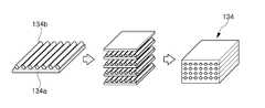
또한, 상기 튜브부재는 제3 층과 제4 층을 서로 번갈아 적층하여 중첩된 복합층 구조로 형성되며, 여기서 제4 층은 탄소섬유 함유층인 것을 특징으로 한다.In addition, the tube member is formed of a composite layer structure in which the third layer and the fourth layer are alternately stacked to form a superposed structure, wherein the fourth layer is a carbon fiber-containing layer.
또한, 상기 튜브부재는, 일정한 간격으로 배열되는 복수개의 메인튜브부재와, 상기 메인튜브부재를 상호 연통시키는 연결튜브부재를 포함하며, 복수개의 메인튜브부재 중 하나에는 메인튜브부재에 가해지는 압력 또는 충격을 감지하여 센싱신호를 생성하는 센서부가 구비되는 것을 특징으로 한다.The tube member may include a plurality of main tube members arranged at regular intervals and a connecting tube member for mutually communicating the main tube member, wherein one of the plurality of main tube members is provided with a pressure And a sensor unit for sensing a shock and generating a sensing signal.
본 발명에 의하면, 에어튜브형태의 튜브부재에 대한 압력 또는 충격을 감지하는 센서를 부착하여, 외부 압력 또는 충격이 가해지는 경우, 센서가 튜브부재의 압축되는 양 등을 센싱하여 이를 제어부에 전달하여 기계장치, 로봇 등의 구동을 제어할 수 있으므로, 장애물과의 충돌 시 충격을 충분히 완화할 수 있고 기계장치 및 장애물의 쌍방 기계적 손상을 최소한으로 억제할 수 있는 효과가 있다.According to the present invention, a sensor for sensing a pressure or an impact on an air tube-shaped tube member is attached, and when an external pressure or impact is applied, the sensor senses the amount of compression of the tube member, It is possible to sufficiently mitigate the impact upon collision with an obstacle and to minimize the mechanical damage to both the mechanical device and the obstacle.
또한, 플렉시블한 자성시트의 적용에 의해 장착이 용이해지는 효과가 있다.In addition, the application of the flexible magnetic sheet facilitates the mounting.
또한, 튜브부재 자체가 탄성력을 제공하여 외부 압력 또는 충격으로부터 기계장치, 로봇 등을 기계적으로 보호하는 이중의 보호효과를 가진다.In addition, the tube member itself provides an elastic force and has a dual protection effect for mechanically protecting a mechanical device, a robot, and the like from external pressure or impact.
도 1은 본 발명에 따른 기계장치 보호용 에어패드의 구성을 개략적으로 도시한 단면도이다.
도 2는 도 1의 튜브부재("A" 부분)가 이중층의 구조로 형성됨을 보여주는 도면이다.
도 3은 도 1의 튜브부재("A" 부분)가 다중층의 구조로 형성됨을 보여주는 도면이다.
도 4는 도 1의 압력조절부의 구성을 나타내는 도면이다.
도 5는 본 발명에 따른 기계장치 보호용 에어패드의 적용예를 도시하는 도면이다.
도 6은 본 발명의 다른 실시예에 따른 기계장치 보호용 에어패드의 구성을 나타내는 도면이다.1 is a cross-sectional view schematically showing the construction of an air pad for protecting a mechanical device according to the present invention.
Fig. 2 is a view showing that the tube member ("A" part) of Fig. 1 is formed with a bilayer structure.
Figure 3 is a view showing that the tube member ("A" portion) of Figure 1 is formed in a multi-layered structure.
4 is a view showing the configuration of the pressure regulating portion of FIG.
5 is a view showing an application example of an air pad for protecting a mechanical device according to the present invention.
6 is a view showing a configuration of an air pad for protecting a mechanical device according to another embodiment of the present invention.
본 명세서 및 청구범위에 사용된 용어나 단어는 통상적이거나 사전적인 의미로 한정해서 해석되어서는 아니되며, 발명자는 그 자신의 발명을 가장 최선의 방법으로 설명하기 위해 용어의 개념을 적절하게 정의할 수 있다는 원칙에 입각하여 본 발명의 기술적 사상에 부합하는 의미와 개념으로 해석되어야만 한다.The terms and words used in the present specification and claims should not be construed as limited to ordinary or dictionary terms and the inventor may appropriately define the concept of the term in order to best describe its invention It should be construed as meaning and concept consistent with the technical idea of the present invention.
따라서, 본 명세서에 기재된 실시예와 도면에 도시된 구성은 본 발명의 가장 바람직한 일 실시예에 불과할 뿐이고 본 발명의 기술적 사상을 모두 대변하는 것은 아니므로, 본 출원시점에 있어서 이들을 대체할 수 있는 다양한 균등물과 변형예들이 있을 수 있음을 이해하여야 한다.Therefore, the embodiments described in this specification and the configurations shown in the drawings are merely the most preferred embodiments of the present invention and do not represent all the technical ideas of the present invention. Therefore, It is to be understood that equivalents and modifications are possible.
이하 첨부된 본 발명의 바람직한 실시예를 상세히 설명한다.Hereinafter, preferred embodiments of the present invention will be described in detail.
본 발명의 실시예에 있어서, 본 발명의 에어패드는 기계장치를 보호하는 기계장치 보호용 에어패드로서 설명하고 있지만, 제조, 운반, 검사 또는 서비스에서 기계장치, 로봇 및 이들의 매니퓰레이터를 보호하는 용도로서 사용될 수 있음은 물론이다.In the embodiment of the present invention, the air pad of the present invention is described as an air pad for protecting a mechanical device. However, the present invention is not limited to the use of the air pad for protecting mechanical devices, robots and manipulators thereof in manufacturing, Of course.
도 1은 본 발명에 따른 기계장치 보호용 에어패드의 구성을 개략적으로 도시한 단면도이다.1 is a cross-sectional view schematically showing the construction of an air pad for protecting a mechanical device according to the present invention.
도 1을 참조하면, 기계장치 보호용 에어패드(100)는 베이스기재(110)와, 자성시트(120)와, 튜브부재(130)와, 기체주입부(140)와, 압력센서(150)와, 압력조절부(160)와, 제어부(도시안됨)를 포함하여 구성된다.1, an
베이스기재(110)는 구성요소가 부품이 실장될 수 있는 기재로서, 인쇄회로기판으로서 설계될 수 있다. 바람직하게는, 휨성이 우수한 플렉시블 기판으로서 설계될 수 있다.The
자성시트(120)는 자성체를 휨성이 우수한 플렉시블 시트 형태로 성형하여 형성될 수 있다. 이러한 자성시트(120)는 기계장치 등의 원하는 부위에 자력에 의해 부착하는 방식으로 간단하게 결합시킬 수 있다.The
자성시트(120)는 접착제에 의해 베이스기재(110)에 일면에 결합될 수 있다.The
여기서, 자성시트(120)는 플렉시블한 특성을 얻기 위해 바인더 등의 수지에 금속 자성 분말을 혼합하여 시트상으로 제조한 자성 소재가 자성시트로 활용될 수 있다. 이러한 자성시트(120)에 사용되는 금속 자성 분말은 평균입도 50㎛의 Fe-Si-Cr 합금, Fe-Si-Al 합금, Fe-Cu-Nb-Si-B 합금, 또는 FeSi합금 등의 여러 가지 자성 재료를 사용할 수 있다.Here, in order to obtain flexible characteristics, the
플렉시블 자성시트를 제조하는 방법은, 연자성 금속 분말을 편평상 입자로 제조하고, 상기 편평상의 연자성 금속 분말을 바인더와 혼합하여 복합 조성물을 제조한 후에, 복합 조성물을 내열성 이형 필름상에 도포하여 경화시켜 필름을 형성하고 상기 필름으로부터 이형 필름을 제거하여 얻어진 원단을 두께에 맞게 적층하고 일정한 온도, 압력으로 가압 성형하여 자성 시트를 제조하는 공정을 포함할 수 있다.The method for producing a flexible magnetic sheet is a method for producing a flexible magnetic sheet by preparing a soft magnetic metal powder as flat particles and mixing the flat soft magnetic metal powder with a binder to prepare a composite composition, Curing the film to form a film, removing the release film from the film, laminating the obtained fabric in a thickness-wise manner, and press-forming the film at a constant temperature and pressure to produce a magnetic sheet.
또한, 도면에 도시되지는 않았지만, 자성시트(120)에는 유연성의 방향성을 부여하기 위해 다수의 홈(소정 깊이 만큼 오목하게 들어가도록 형성된 선을 지칭함)을 형성할 수 있다. 다수의 홈은 자성 시트(120)의 가로방향을 따라 평행하게 형성된 홈과, 세로 방향을 따라 평행하게 형성된 홈일 수 있다. 바람직하게, 이러한 홈은 스탬프를 이용하여 1회의 스탬핑 작업만으로 형성될 수 있다.Although not shown in the drawings, the
튜브부재(130)는 베이스기재(120) 상에 설치되고 에어 또는 가스와 같은 기체 주입이 가능하다. 튜브부재(130)의 내부에 기체를 주입시키면 팽팽하게 팽창함으로써 장애물과의 충돌 시 충격을 충분히 완화할 수 있고 기계장치 및 장애물의 쌍방 기계적 손상을 최소한으로 억제할 수 있도록 한다.The
튜브부재(130)는 이중층 구조 또는 다중층 구조로 형성될 수 있는데, 이에 대해서는 후술하기로 한다.The
기체주입부(140)는 상기 튜브부재(30) 내부로 기체를 공급할 수 있다.The
예를 들면, 기체주입부(140)는 에어펌프와, 상기 에어펌프를 구동하는 구동모터를 포함하여 주입공(142)을 통해 튜브부재(130) 내부로 에어를 공급할 수 있다.For example, the gas injecting
압력센서(150)는 상기 튜브부재(130) 내부의 압력변화를 센싱하여 압력신호를 생성할 수 있다.The
다른 실시예에서, 기계장치 보호용 에어패드는, 상기 압력센서(150) 이외에도, 상기 튜브부재(130)에 가해지는 충격을 센싱하여 충격신호를 생성할 수 있는 충격센서를 더 포함할 수 있다.The air pad for protecting a mechanical device may further include an impact sensor capable of sensing an impact applied to the
압력조절부(160)는 하기에서 상세히 설명되는 바와 같이 제어부의 제어에 따라 상기 튜브부재(130)의 내외부공간을 선택적으로 연결하여 상기 튜브부재(130)의 압력을 조절하도록 구성될 수 있다.The
제어부는 상기 압력신호(또는 충격신호)에 대응하여 기설정된 설정압력 이상에서 경보신호를 생성하고, 기계장치, 로봇 및 이들의 매니퓰레이터의 구동을 정지시키는 신호를 생성할 수 있다. 따라서, 장애물과의 충돌 시 충격을 충분히 완화할 수 있고 기계장치 및 장애물의 쌍방 기계적 손상을 최소한으로 억제할 수 있는 효과가 있다.The control unit may generate an alarm signal at a predetermined set pressure or higher in response to the pressure signal (or the shock signal), and generate a signal for stopping the operation of the mechanical device, the robot and their manipulators. Therefore, it is possible to sufficiently mitigate the impact upon collision with the obstacle, and to minimize the mechanical damages of both the mechanical device and the obstacle.
이 경우, 부저 또는 램프(도시안됨)가 추가로 제공됨으로써, 상기 경보신호에 따라 부저음을 출력하거나 점등이 이루어지도록 구성할 수도 있다.In this case, a buzzer or a lamp (not shown) may be additionally provided so that buzzer sound is outputted or lit according to the alarm signal.
도 2는 도 1의 튜브부재("A" 부분)가 이중층의 구조로 형성됨을 보여주는 도면이고, 도 3은 도 1의 튜브부재("A" 부분)가 다중층의 구조로 형성됨을 보여주는 도면이다.FIG. 2 is a view showing that the tube member ("A" portion) of FIG. 1 is formed of a bilayer structure, and FIG. 3 is a view showing that the tube member ("A" .
도 2를 참조하면, 상기 튜브부재(130)는 제1 층(132a)과 제2 층(132b)의 이중층 구조(132)로 형성되며, 제1 층(132a)의 일면에는 육각 기둥형태의 육각셀(132a1)이 일정간격으로 반복 배열되어 있고, 제2 층(132b)의 일면에는 육각 기둥형태의 육각셀(132b1)이 일정간격으로 반복 배열되어 있다.2, the
또한, 상기 육각셀(132a1; 132b1)의 중앙에는 경량화 및 접착강도의 증가를 목적으로 하는 관통공(132a2; 132b2)을 구비하고 있다.The hexagonal cells 132a1 and 132b1 are provided with through-holes 132a2 and 132b2 at the center thereof for weight reduction and increase in adhesive strength.
이와 같이 구성된 제1 층(132a)과 제2 층(132b)을 육각셀(132a1; 132b1)이 돌출된 측으로 중첩시켜 접착하게 되면 이중층 구조(132)가 형성될 수 있다. 이때, 접착제가 육각셀(132a1; 132b1)의 표면에 도포되고 관통공(132a2; 132b2)에 충전되어 각각의 육각셀(132a1; 132b1)이 견고히 접착되어 일체가 되도록 할 수 있다.When the
도 3을 참조하면, 상기 튜브부재(130)는 제3 층(134a)과 제4 층(134b)을 서로 번갈아 적층하여 중첩된 복합층 구조(134)로 형성될 수 있으며, 여기서 제4 층(134b)은 예를 들면 탄소섬유 함유층인 것을 특징으로 한다.Referring to FIG. 3, the
탄소섬유는 튜브부재(30)의 경량화와, 순간 충격에 따른 파손 방지, 굴곡강도, 굴곡탄성을 향상시킬 목적으로 적용되고 있다.The carbon fiber is applied for the purpose of reducing the weight of the tube member 30, preventing breakage due to an instantaneous impact, improving bending strength and bending elasticity.
탄소섬유는, 피치계 탄소섬유, PAN계 탄소섬유, 피치계 혹은 PAN계 탄소섬유를 가열재처리한 탄소섬유, 기상성장 탄소섬유, 카본 나노화이버, 단층벽 카본나노튜브, 다중벽 카본나노튜브, 또는 이들의 집합체일 수 있다. 또한, 본 발명의 중첩된 복합구조(134)에서는, 1종의 탄소섬유를 단독체로서 사용하여도 좋고, 또는 여러 종류의 탄소섬유를 혼합한 복합체를 탄소섬유로서 사용해도 좋다.The carbon fiber may be carbon fiber obtained by heat-treating the pitch-based carbon fiber, the PAN-based carbon fiber, the pitch-based or PAN-based carbon fiber, the vapor grown carbon fiber, the carbon nanofiber, the single wall carbon nanotube, Or a combination thereof. In addition, in the overlapped
복합층 구조(134)는, 제3 층(134a)과 제4 층(134b)를 접촉시킨 상태에서 가열압접하여, 제3 층(134a)의 일부를 소성변형시키고 제4 층(134b)의 주위를 둘러싸도록 하여 형성할 수 있다.The
제3 층(134a)과 제4 층(134b)을 서로 번갈아 적층할 때, 제4 층(134b), 즉 탄소섬유 함유층에 함유되는 탄소섬유를 일방향으로 정렬시킴으로써, 복합층 구조(134)의 탄소섬유 정렬방향에서의 기계강도를 더욱 향상시킬 수 있다.When the
본 발명의 복합층 구조(134)는 그 적층방향에 있어서 01~10mm, 바람직하게는 01~3mm의 두께를 가지는 시트형상 재료로서 얻을 수 있다. 이와 같이 얇은 시트형상 재료로 한 경우, 제조후에 휨 변형을 가한 경우, 파단 등의 미세조직적 파괴가 발생하지 않고, 열적 성질(열전도율, 열팽창율 등)의 열화를 방지할 수 있다.The
도 4는 도 1의 압력조절부의 구성을 나타내는 도면이다.4 is a view showing the configuration of the pressure regulating portion of FIG.
도 4를 참조하면, 압력조절부(160)는, 상기 튜브부재(130)의 내외부 공간을 연결하도록 기체배출구(161a)가 형성되는 판형부재(161)와, 상기 판형부재(161)의 저면에 일체로 결합되면서 외주면에는 외부와 연결되는 다수개의 관통구(162a)가 형성되는 케이스부(162)와, 상기 케이스부(162)의 내부공간에 고정되도록 설치되어 상기 제어부의 제어에 따라 선택적으로 구동되는 모터부(163)와, 상기 모터부(163)의 선단에 결합되어 상기 기체배출구(161a)의 개방각도를 단속하는 단속부(165)를 포함하여 구성된다. 미설명 도면부호 164는 모터축을 나타낸다.4, the
앞서 언급된 바와 같이, 압력조절부(160)는 제어부의 제어에 따라 튜브부재(130)의 내외부공간을 선택적으로 연결하여 튜브부재(130)의 압력을 조절하도록 할 수 있다.As described above, the
센싱된 감지값이 기설정된 임계값 이상이면, 제어부는 장애물과의 충돌 시 충격이 큰 것으로 판단하고, 튜브부재(130) 내의 기체가 압력조절부(160)를 통해 외부로 배출되지 못하도록 제어하여 튜브부재(130)의 팽창력이 증가됨으로써 기계장치 및 장애물의 쌍방 기계적 손상을 최소한으로 억제할 수 있다.If the sensed sensed value is greater than a preset threshold value, the control unit determines that the impact on the obstacle is large, and controls the gas in the
구체적으로는, 단속부(165)가 기체배출구(161a)를 완전히 밀폐시키도록 모터부(163)의 작동을 제어하게 된다.Specifically, the operation of the
또한, 센싱된 감지값이 기설정된 임계값 이하이면, 제어부는 장애물과의 충돌 시 충격이 작은 것으로 판단하고, 튜브부재(130) 내의 기체가 압력조절부(160)를 통해 외부로 배출되도록 제어하여 튜브부재(130)의 반발력을 감소시킴으로써 기계장치 및 장애물의 쌍방 기계적 손상을 최소한으로 억제할 수 있다.If the sensed sensed value is less than a preset threshold value, the controller determines that the impact is small when colliding with an obstacle, and controls the gas in the
구체적으로는, 단속부(165)가 시계방향 또는 반시계 방향으로 일정 각도 만큼 회전되면서 기체배출구(161a)를 일정 범위만큼 개방시키도록 모터부(163)의 작동을 제어하게 된다.Specifically, the operation of the
도 5는 본 발명에 따른 기계장치 보호용 에어패드의 적용예를 도시하는 도면이다.5 is a view showing an application example of an air pad for protecting a mechanical device according to the present invention.
도 5를 참조하면, 본 발명에 따른 기계장치 보호용 에어패드(100)는 제조, 운반, 검사 또는 서비스에서 사용되는 로봇의 매니퓰레이터에 적용할 수 있다.Referring to FIG. 5, the
구체적으로는, 본 발명에 따른 기계장치 보호용 에어패드(100)는 예를 들면 자성시트(120)에 의해 매니퓰레이터의 아암부 또는 관절부에 부착될 수 있다. 이를 위해서, 본 발명에 따른 기계장치 보호용 에어패드(100)는 다양한 부착 위치에 적용가능하도록 다양한 형상으로 제조될 수 있음은 물론이다.Specifically, the
도 6은 본 발명의 다른 실시예에 따른 기계장치 보호용 에어패드의 구성을 나타내는 도면이다.6 is a view showing a configuration of an air pad for protecting a mechanical device according to another embodiment of the present invention.
도 6을 참조하면, 전술한 실시예와 비교할 때, 기계장치 보호용 에어패드(200)는 복수개의 메인튜브부재(230, 330, 440), 및 연결튜브부재(510, 520)를 포함하여 구성되는 점에서 차이를 가진다.6, an
복수개의 메인튜브부재(230, 330, 440)는 일정한 간격으로 배열되어 있다. 본 실시예에서는 3개의 메인튜브부재의 예를 들고 있으나, 이에 한정되는 것은 아니다.The plurality of
연결튜브부재(510, 520)는 메인튜브부재(230, 330, 440)를 상호 연통시킨다.The connecting
메인튜브부재(230, 330, 440) 및 연결튜브부재(510, 520)는 일체로 형성되며, 도 2의 이중층의 구조 또는 도 3의 다중층의 구조로 형성될 수 있다.The
메인튜브부재(230)는 플렉시블한 베이스기재(210) 상에 설치되고, 기체주입부(240)를 통해 메인튜브부재 내부로 기체를 공급할 수 있고, 센서부(250)에 의해 메인튜브부재에 가해지는 압력 또는 충격을 감지하여 센싱신호를 생성하고, 제어부(도시안됨)가 상기 센싱신호에 대응하여 기설정된 임계값 이상이면 경보신호를 생성하고, 동시에 기계장치의 구동을 정지시킬 수 있다. 미설명 도면부호 242는 주입공을 나타낸다.The
또한, 베이스기재(210)의 하면에 구비되어 기계장치의 표면에 부착되는 자성시트(220)를 포함한다.And a
또한, 압력조절부(260)가 제공되어 메인튜브부재의 압력을 조절하도록 구성할 수 있다.Also, a
메인튜브부재(330)는 플렉시블한 베이스기재(310) 상에 설치되고, 베이스기재(310)의 하면에 구비된 자성시트(320)에 의해 기계장치의 표면에 부착될 수 있다.The
메인튜브부재(430)는 플렉시블한 베이스기재(410) 상에 설치되고, 베이스기재(410)의 하면에 구비된 자성시트(420)에 의해 기계장치의 표면에 부착될 수 있다.The
즉, 메인튜브부재(230)의 기체주입부(240)를 통해 기체가 주입되면, 연결튜브부재(510, 520)를 통해 메인튜브부재(340) 및 메인튜브부재(440)에도 기체가 주입되게 구성된다. 이때, 복수개의 메인튜브부재(230, 330, 440) 중 하나(230)에만 메인튜브부재에 가해지는 압력 또는 충격을 감지하여 센싱신호를 생성하는 센서부(250) 등이 구비됨으로써 제조비용을 절감시킬 수 있다.That is, when the gas is injected through the
본 발명은 이상에서 살펴본 바와 같이 바람직한 실시예를 들어 도시하고 설명하였으나, 상기한 실시예에 한정되지 아니하며 본 발명의 정신을 벗어나지 않는 범위 내에서 당해 발명이 속하는 기술분야에서 통상의 지식을 가진 자에 의해 다양한 변경과 수정이 가능할 것이다.While the present invention has been particularly shown and described with reference to exemplary embodiments thereof, it is clearly understood that the same is by way of illustration and example only and is not to be taken by way of limitation, Various changes and modifications will be possible.
110 : 베이스기재
120 : 자성시트
130 : 튜브부재
140 : 기체주입부
150 : 압력센서
160 : 압력조절부110: base substrate
120: magnetic sheet
130: tube member
140:
150: Pressure sensor
160: Pressure regulator
Claims (16)
Translated fromKorean플렉시블한 베이스기재;
상기 베이스기재 상에 설치되고 기체 주입이 가능한 튜브부재;
상기 튜브부재 내부로 기체를 공급하는 기체주입부;
상기 튜브부재에 가해지는 압력 또는 충격을 감지하여 센싱신호를 생성하는 센서부;
상기 센싱신호에 대응하여 기설정된 임계값 이상이면 경보신호를 생성하고, 상기 기계장치의 구동을 정지시키는 제어신호를 생성하는 제어부; 및
상기 베이스기재의 하면에 구비되어 상기 기계장치의 표면에 부착되는 자성시트를 포함하고,
상기 제어부의 제어에 따라 상기 튜브부재의 내외부공간을 선택적으로 연결하여 상기 튜브부재의 압력을 조절하도록 구성된 압력조절부를 더 포함하며,
상기 압력조절부는,
상기 튜브부재의 내외부 공간을 연결하도록 기체배출구가 형성되는 판형부재와,
상기 판형부재의 저면에 일체로 결합되면서 외주면에는 외부와 연결되는 다수개의 관통구가 형성되는 케이스부와,
상기 케이스부의 내부공간에 고정되도록 설치되어 상기 제어부의 제어에 따라 선택적으로 구동되는 모터부와,
상기 모터부의 선단에 결합되어 상기 기체배출구의 개방각도를 단속하는 단속부를 포함하는 것을 특징으로 하는 기계장치 보호용 에어패드.1. An air pad for protecting a mechanical device attached to a surface of a mechanical device,
A flexible base substrate;
A tube member installed on the base substrate and capable of injecting gas;
A gas injection unit for supplying gas into the tube member;
A sensor unit for sensing a pressure or an impact applied to the tube member to generate a sensing signal;
A control unit for generating an alarm signal when the sensed signal is equal to or greater than a predetermined threshold value and generating a control signal for stopping the driving of the mechanical device; And
And a magnetic sheet provided on a lower surface of the base substrate and attached to a surface of the mechanical device,
Further comprising a pressure regulator configured to selectively regulate the pressure of the tube member by selectively connecting the inner and outer spaces of the tube member under the control of the controller,
The pressure regulator may include:
A plate-shaped member having a gas outlet port for connecting the inner and outer spaces of the tube member,
A case portion integrally coupled to a bottom surface of the plate member and having a plurality of through holes connected to the outside on an outer circumferential surface thereof,
A motor unit installed to be fixed in an inner space of the case unit and selectively driven according to the control of the control unit,
And an intermittent portion coupled to a front end of the motor portion and interrupting an opening angle of the gas exhaust port.
상기 자성시트에는 유연성의 방향성을 부여하기 위해 다수의 홈을 형성할 수 있는 것을 특징으로 하는 기계장치 보호용 에어패드.The method according to claim 1,
Wherein a plurality of grooves can be formed in the magnetic sheet so as to impart flexibility of directionality to the magnetic sheet.
상기 튜브부재는 제1 층과 제2 층의 이중층 구조로 형성되며, 제1 층과 제2 층의 일면에는 각각 육각 기둥형태의 육각셀이 일정간격으로 반복 배열되어 있고, 제1 층과 제2 층을 육각셀이 돌출된 측으로 중첩시켜 이중층 구조를 형성하는 것을 특징으로 하는 기계장치 보호용 에어패드.The method according to claim 1,
The tube member is formed of a double layer structure of a first layer and a second layer, and hexagonal column-shaped hexagonal cells are repeatedly arranged at regular intervals on one surface of each of the first layer and the second layer, Layer structure is formed by superimposing the layer on the protruded side of the hexagonal cell.
상기 육각셀의 중앙에는 관통공을 구비하는 것을 특징으로 하는 기계장치 보호용 에어패드.6. The method of claim 5,
And a through hole is formed at the center of the hexagonal cell.
상기 튜브부재는 제3 층과 제4 층을 서로 번갈아 적층하여 중첩된 복합층 구조로 형성될 수 있으며, 여기서 제4 층은 탄소섬유 함유층인 것을 특징으로 하는 기계장치 보호용 에어패드.The method according to claim 1,
Wherein the tube member may be formed as a composite layer structure in which the third layer and the fourth layer are alternately stacked to form a superimposed composite layer structure, wherein the fourth layer is a carbon fiber-containing layer.
상기 튜브부재는,
일정한 간격으로 배열되는 복수개의 메인튜브부재와,
상기 메인튜브부재를 상호 연통시키는 연결튜브부재를 포함하며,
복수개의 메인튜브부재 중 하나에는 메인튜브부재에 가해지는 압력 또는 충격을 감지하여 센싱신호를 생성하는 센서부가 구비되는 것을 특징으로 하는 기계장치 보호용 에어패드.The method according to claim 1,
Wherein the tube member comprises:
A plurality of main tube members arranged at regular intervals,
And a connecting tube member for mutually communicating the main tube member,
Wherein one of the plurality of main tube members is provided with a sensor unit for sensing a pressure or an impact applied to the main tube member to generate a sensing signal.
플렉시블한 베이스기재;
상기 베이스기재 상에 설치되고 기체 주입이 가능한 튜브부재;
상기 튜브부재 내부로 기체를 공급하는 기체주입부;
상기 튜브부재에 가해지는 압력 또는 충격을 감지하여 센싱신호를 생성하는 센서부;
상기 센싱신호에 대응하여 기설정된 임계값 이상이면 경보신호를 생성하고, 상기 로봇의 구동을 정지시키는 제어신호를 생성하는 제어부; 및
상기 베이스기재의 하면에 구비되어 상기 로봇의 표면에 부착되는 플렉시블 자성시트를 포함하고,
상기 제어부의 제어에 따라 상기 튜브부재의 내외부공간을 선택적으로 연결하여 상기 튜브부재의 압력을 조절하도록 구성된 압력조절부를 더 포함하며,
상기 압력조절부는,
상기 튜브부재의 내외부 공간을 연결하도록 기체배출구가 형성되는 판형부재와,
상기 판형부재의 저면에 일체로 결합되면서 외주면에는 외부와 연결되는 다수개의 관통구가 형성되는 케이스부와,
상기 케이스부의 내부공간에 고정되도록 설치되어 상기 제어부의 제어에 따라 선택적으로 구동되는 모터부와,
상기 모터부의 선단에 결합되어 상기 기체배출구의 개방각도를 단속하는 단속부를 포함하는 것을 특징으로 하는 로봇 보호용 에어패드.A robot protecting air pad for protecting a robot by being attached to a surface of the robot,
A flexible base substrate;
A tube member installed on the base substrate and capable of injecting gas;
A gas injection unit for supplying gas into the tube member;
A sensor unit for sensing a pressure or an impact applied to the tube member to generate a sensing signal;
A control unit for generating an alarm signal when the sensed signal is equal to or greater than a preset threshold value and generating a control signal for stopping the driving of the robot; And
And a flexible magnetic sheet provided on a lower surface of the base substrate and attached to a surface of the robot,
Further comprising a pressure regulator configured to selectively regulate the pressure of the tube member by selectively connecting the inner and outer spaces of the tube member under the control of the controller,
The pressure regulator may include:
A plate-shaped member having a gas outlet port for connecting the inner and outer spaces of the tube member,
A case portion integrally coupled to a bottom surface of the plate member and having a plurality of through holes connected to the outside on an outer circumferential surface thereof,
A motor unit installed to be fixed in an inner space of the case unit and selectively driven according to the control of the control unit,
And an intermittent portion coupled to a front end of the motor portion for interrupting the opening angle of the gas exhaust port.
상기 플렉시블 자성시트에는 유연성의 방향성을 부여하기 위해 다수의 홈을 형성할 수 있는 것을 특징으로 하는 로봇 보호용 에어패드.10. The method of claim 9,
Wherein a plurality of grooves can be formed in the flexible magnetic sheet to impart flexibility directionality to the flexible magnetic sheet.
상기 튜브부재는 제1 층과 제2 층의 이중층 구조로 형성되며, 제1 층과 제2 층의 일면에는 각각 육각 기둥형태의 육각셀이 일정간격으로 반복 배열되어 있고, 제1 층과 제2 층을 육각셀이 돌출된 측으로 중첩시켜 이중층 구조를 형성하는 것을 특징으로 하는 로봇 보호용 에어패드.10. The method of claim 9,
The tube member is formed of a double layer structure of a first layer and a second layer, and hexagonal column-shaped hexagonal cells are repeatedly arranged at regular intervals on one surface of each of the first layer and the second layer, Layer structure is formed by superimposing the layer on the protruded side of the hexagonal cell.
상기 육각셀의 중앙에는 관통공을 구비하는 것을 특징으로 하는 로봇 보호용 에어패드.14. The method of claim 13,
Wherein the hexagonal cell has a through hole at the center thereof.
상기 튜브부재는 제3 층과 제4 층을 서로 번갈아 적층하여 중첩된 복합층 구조로 형성되며, 여기서 제4 층은 탄소섬유 함유층인 것을 특징으로 하는 로봇 보호용 에어패드.10. The method of claim 9,
Wherein the tube member is formed as a composite layer structure in which the third layer and the fourth layer are alternately stacked one upon the other, wherein the fourth layer is a carbon fiber-containing layer.
상기 튜브부재는,
일정한 간격으로 배열되는 복수개의 메인튜브부재와,
상기 메인튜브부재를 상호 연통시키는 연결튜브부재를 포함하며,
복수개의 메인튜브부재 중 하나에는 메인튜브부재에 가해지는 압력 또는 충격을 감지하여 센싱신호를 생성하는 센서부가 구비되는 것을 특징으로 하는 로봇 보호용 에어패드.10. The method of claim 9,
Wherein the tube member comprises:
A plurality of main tube members arranged at regular intervals,
And a connecting tube member for mutually communicating the main tube member,
Wherein one of the plurality of main tube members is provided with a sensor unit for sensing a pressure or an impact applied to the main tube member to generate a sensing signal.
Priority Applications (1)
| Application Number | Priority Date | Filing Date | Title |
|---|---|---|---|
| KR1020190022233AKR102001569B1 (en) | 2019-02-26 | 2019-02-26 | Air pad for protection of machinery |
Applications Claiming Priority (1)
| Application Number | Priority Date | Filing Date | Title |
|---|---|---|---|
| KR1020190022233AKR102001569B1 (en) | 2019-02-26 | 2019-02-26 | Air pad for protection of machinery |
Publications (1)
| Publication Number | Publication Date |
|---|---|
| KR102001569B1true KR102001569B1 (en) | 2019-07-18 |
Family
ID=67469421
Family Applications (1)
| Application Number | Title | Priority Date | Filing Date |
|---|---|---|---|
| KR1020190022233AActiveKR102001569B1 (en) | 2019-02-26 | 2019-02-26 | Air pad for protection of machinery |
Country Status (1)
| Country | Link |
|---|---|
| KR (1) | KR102001569B1 (en) |
Cited By (1)
| Publication number | Priority date | Publication date | Assignee | Title |
|---|---|---|---|---|
| CN113146684A (en)* | 2021-04-26 | 2021-07-23 | 武汉东余自动化科技有限公司 | Safety device for debugging of robot |
Citations (8)
| Publication number | Priority date | Publication date | Assignee | Title |
|---|---|---|---|---|
| JPH08393A (en) | 1994-06-16 | 1996-01-09 | Okamura Corp | Adjustment device for breadthwise space between chair armrests |
| JP2945536B2 (en)* | 1992-03-25 | 1999-09-06 | 株式会社竹中工務店 | Work machine safety devices |
| US20040186626A1 (en) | 2001-08-20 | 2004-09-23 | Katsunori Tsukamoto | Robot hand |
| KR20100044617A (en)* | 2008-10-22 | 2010-04-30 | 현대모비스 주식회사 | The curtain air-bag prevention apparatus which sagging |
| JP2011249850A (en)* | 2011-09-01 | 2011-12-08 | Panasonic Corp | Magnetic sheet |
| JP5013157B2 (en)* | 2005-10-28 | 2012-08-29 | 株式会社デンソー | Vehicle collision detection device |
| CN103249530A (en) | 2010-12-16 | 2013-08-14 | 罗伯特·博世有限公司 | Method for operating a guard for a handling device, guard for a handling device, and handling device |
| KR20170026462A (en) | 2014-07-03 | 2017-03-08 | 블루 다뉴브 로보틱스 게엠베하 | Protection method and protection device for a handling apparatus |
- 2019
- 2019-02-26KRKR1020190022233Apatent/KR102001569B1/enactiveActive
Patent Citations (9)
| Publication number | Priority date | Publication date | Assignee | Title |
|---|---|---|---|---|
| JP2945536B2 (en)* | 1992-03-25 | 1999-09-06 | 株式会社竹中工務店 | Work machine safety devices |
| JPH08393A (en) | 1994-06-16 | 1996-01-09 | Okamura Corp | Adjustment device for breadthwise space between chair armrests |
| US20040186626A1 (en) | 2001-08-20 | 2004-09-23 | Katsunori Tsukamoto | Robot hand |
| JP5013157B2 (en)* | 2005-10-28 | 2012-08-29 | 株式会社デンソー | Vehicle collision detection device |
| KR20100044617A (en)* | 2008-10-22 | 2010-04-30 | 현대모비스 주식회사 | The curtain air-bag prevention apparatus which sagging |
| CN103249530A (en) | 2010-12-16 | 2013-08-14 | 罗伯特·博世有限公司 | Method for operating a guard for a handling device, guard for a handling device, and handling device |
| US9296106B2 (en) | 2010-12-16 | 2016-03-29 | Robert Bosch Gmbh | Method for operating a safety device for a handling device, safety device for a handling device, and handling device |
| JP2011249850A (en)* | 2011-09-01 | 2011-12-08 | Panasonic Corp | Magnetic sheet |
| KR20170026462A (en) | 2014-07-03 | 2017-03-08 | 블루 다뉴브 로보틱스 게엠베하 | Protection method and protection device for a handling apparatus |
Cited By (1)
| Publication number | Priority date | Publication date | Assignee | Title |
|---|---|---|---|---|
| CN113146684A (en)* | 2021-04-26 | 2021-07-23 | 武汉东余自动化科技有限公司 | Safety device for debugging of robot |
Similar Documents
| Publication | Publication Date | Title |
|---|---|---|
| US20250230650A1 (en) | Sound insulation sheet member and sound insulation structure using same | |
| AU2016329109B2 (en) | Flexible MEMS printed circuit board unit and sound transducer assembly | |
| ES2257367T3 (en) | ELECTROMECHANICAL FUNCTIONAL MODULE. | |
| US20080203851A1 (en) | Piezoelectric package with porous conductive layers | |
| US8106565B2 (en) | Piezoceramic multilayer actuator with stress relief sections and insulation layers in sections without relief zones | |
| US8461745B2 (en) | Piezoceramic surface actuator and method for the production thereof | |
| KR102001569B1 (en) | Air pad for protection of machinery | |
| KR101653061B1 (en) | Electro active polymer fabric sensor for detecting transformation | |
| CN112349676B (en) | Semi-flexible component carrier and method for producing the same | |
| EP3240304A1 (en) | Acoustic membrane | |
| JP2013522865A (en) | Bending transducer | |
| KR20160002725A (en) | Lightweight thermal shield | |
| US20170047560A1 (en) | Exterior package for flexible electrochemical device and electrochemical device including the exterior package | |
| KR102491990B1 (en) | Battery pack with laminate for reducing the impact of lateral tear and manufacturing method thereof | |
| CN105637691A (en) | The fuel cell | |
| JP6897730B2 (en) | Battery pack pressure release valve | |
| CN101432902B (en) | Piezoelectric actuator with gradient encapsulation layer and method for the production thereof | |
| JP5096918B2 (en) | Apparatus and method for influencing planar element vibration | |
| US10596779B2 (en) | Composite material structure | |
| JP6791900B2 (en) | Control device | |
| EP1831936B1 (en) | Piezoelectric bimorph actuator and method of manufacturing thereof | |
| KR20130112336A (en) | Vacuum heat insulating member and manufacturing method for the same | |
| CN219912249U (en) | High-strength light-weight heat insulation plate | |
| CN221352947U (en) | Heat transfer suppressing sheet and battery pack | |
| JP2011033194A (en) | Laminated rubber body containing lead plug |
Legal Events
| Date | Code | Title | Description |
|---|---|---|---|
| PA0109 | Patent application | Patent event code:PA01091R01D Comment text:Patent Application Patent event date:20190226 | |
| PA0201 | Request for examination | ||
| PA0302 | Request for accelerated examination | Patent event date:20190226 Patent event code:PA03022R01D Comment text:Request for Accelerated Examination | |
| PE0902 | Notice of grounds for rejection | Comment text:Notification of reason for refusal Patent event date:20190311 Patent event code:PE09021S01D | |
| PE0701 | Decision of registration | Patent event code:PE07011S01D Comment text:Decision to Grant Registration Patent event date:20190412 | |
| GRNT | Written decision to grant | ||
| PR0701 | Registration of establishment | Comment text:Registration of Establishment Patent event date:20190712 Patent event code:PR07011E01D | |
| PR1002 | Payment of registration fee | Payment date:20190715 End annual number:3 Start annual number:1 | |
| PG1601 | Publication of registration | ||
| PR1001 | Payment of annual fee | Payment date:20220704 Start annual number:4 End annual number:4 | |
| PR1001 | Payment of annual fee | Payment date:20230712 Start annual number:5 End annual number:5 | |
| PR1001 | Payment of annual fee | Payment date:20240129 Start annual number:6 End annual number:6 | |
| PR1001 | Payment of annual fee | Payment date:20250120 Start annual number:7 End annual number:7 |