KR101999958B1 - Mobile terminal and control method thereof - Google Patents
Mobile terminal and control method thereofDownload PDFInfo
- Publication number
- KR101999958B1 KR101999958B1KR1020130057889AKR20130057889AKR101999958B1KR 101999958 B1KR101999958 B1KR 101999958B1KR 1020130057889 AKR1020130057889 AKR 1020130057889AKR 20130057889 AKR20130057889 AKR 20130057889AKR 101999958 B1KR101999958 B1KR 101999958B1
- Authority
- KR
- South Korea
- Prior art keywords
- screen information
- unit
- display unit
- projection
- touch
- Prior art date
- Legal status (The legal status is an assumption and is not a legal conclusion. Google has not performed a legal analysis and makes no representation as to the accuracy of the status listed.)
- Ceased
Links
Images


Classifications
- G—PHYSICS
- G06—COMPUTING OR CALCULATING; COUNTING
- G06F—ELECTRIC DIGITAL DATA PROCESSING
- G06F1/00—Details not covered by groups G06F3/00 - G06F13/00 and G06F21/00
- G06F1/16—Constructional details or arrangements
- G06F1/1613—Constructional details or arrangements for portable computers
- G06F1/163—Wearable computers, e.g. on a belt
- G—PHYSICS
- G06—COMPUTING OR CALCULATING; COUNTING
- G06F—ELECTRIC DIGITAL DATA PROCESSING
- G06F1/00—Details not covered by groups G06F3/00 - G06F13/00 and G06F21/00
- G06F1/16—Constructional details or arrangements
- G06F1/1613—Constructional details or arrangements for portable computers
- G06F1/1633—Constructional details or arrangements of portable computers not specific to the type of enclosures covered by groups G06F1/1615 - G06F1/1626
- G06F1/1637—Details related to the display arrangement, including those related to the mounting of the display in the housing
- G06F1/1639—Details related to the display arrangement, including those related to the mounting of the display in the housing the display being based on projection
- G—PHYSICS
- G06—COMPUTING OR CALCULATING; COUNTING
- G06F—ELECTRIC DIGITAL DATA PROCESSING
- G06F1/00—Details not covered by groups G06F3/00 - G06F13/00 and G06F21/00
- G06F1/16—Constructional details or arrangements
- G06F1/1613—Constructional details or arrangements for portable computers
- G06F1/1633—Constructional details or arrangements of portable computers not specific to the type of enclosures covered by groups G06F1/1615 - G06F1/1626
- G06F1/1637—Details related to the display arrangement, including those related to the mounting of the display in the housing
- G06F1/1643—Details related to the display arrangement, including those related to the mounting of the display in the housing the display being associated to a digitizer, e.g. laptops that can be used as penpads
- G—PHYSICS
- G06—COMPUTING OR CALCULATING; COUNTING
- G06F—ELECTRIC DIGITAL DATA PROCESSING
- G06F1/00—Details not covered by groups G06F3/00 - G06F13/00 and G06F21/00
- G06F1/16—Constructional details or arrangements
- G06F1/1613—Constructional details or arrangements for portable computers
- G06F1/1633—Constructional details or arrangements of portable computers not specific to the type of enclosures covered by groups G06F1/1615 - G06F1/1626
- G06F1/1637—Details related to the display arrangement, including those related to the mounting of the display in the housing
- G06F1/1647—Details related to the display arrangement, including those related to the mounting of the display in the housing including at least an additional display
- G—PHYSICS
- G06—COMPUTING OR CALCULATING; COUNTING
- G06F—ELECTRIC DIGITAL DATA PROCESSING
- G06F3/00—Input arrangements for transferring data to be processed into a form capable of being handled by the computer; Output arrangements for transferring data from processing unit to output unit, e.g. interface arrangements
- G06F3/01—Input arrangements or combined input and output arrangements for interaction between user and computer
- G06F3/017—Gesture based interaction, e.g. based on a set of recognized hand gestures
- G—PHYSICS
- G06—COMPUTING OR CALCULATING; COUNTING
- G06F—ELECTRIC DIGITAL DATA PROCESSING
- G06F3/00—Input arrangements for transferring data to be processed into a form capable of being handled by the computer; Output arrangements for transferring data from processing unit to output unit, e.g. interface arrangements
- G06F3/01—Input arrangements or combined input and output arrangements for interaction between user and computer
- G06F3/03—Arrangements for converting the position or the displacement of a member into a coded form
- G06F3/041—Digitisers, e.g. for touch screens or touch pads, characterised by the transducing means
- G—PHYSICS
- G06—COMPUTING OR CALCULATING; COUNTING
- G06F—ELECTRIC DIGITAL DATA PROCESSING
- G06F3/00—Input arrangements for transferring data to be processed into a form capable of being handled by the computer; Output arrangements for transferring data from processing unit to output unit, e.g. interface arrangements
- G06F3/01—Input arrangements or combined input and output arrangements for interaction between user and computer
- G06F3/048—Interaction techniques based on graphical user interfaces [GUI]
- G06F3/0487—Interaction techniques based on graphical user interfaces [GUI] using specific features provided by the input device, e.g. functions controlled by the rotation of a mouse with dual sensing arrangements, or of the nature of the input device, e.g. tap gestures based on pressure sensed by a digitiser
- G06F3/0488—Interaction techniques based on graphical user interfaces [GUI] using specific features provided by the input device, e.g. functions controlled by the rotation of a mouse with dual sensing arrangements, or of the nature of the input device, e.g. tap gestures based on pressure sensed by a digitiser using a touch-screen or digitiser, e.g. input of commands through traced gestures
- G06F3/04883—Interaction techniques based on graphical user interfaces [GUI] using specific features provided by the input device, e.g. functions controlled by the rotation of a mouse with dual sensing arrangements, or of the nature of the input device, e.g. tap gestures based on pressure sensed by a digitiser using a touch-screen or digitiser, e.g. input of commands through traced gestures for inputting data by handwriting, e.g. gesture or text
Landscapes
- Engineering & Computer Science (AREA)
- Theoretical Computer Science (AREA)
- General Engineering & Computer Science (AREA)
- Computer Hardware Design (AREA)
- Human Computer Interaction (AREA)
- Physics & Mathematics (AREA)
- General Physics & Mathematics (AREA)
- Telephone Function (AREA)
- Computer Networks & Wireless Communication (AREA)
- Signal Processing (AREA)
Abstract
Translated fromKoreanDescription
Translated fromKorean본 발명은 이동 단말기에 관한 것으로, 보다 구체적으로 손목을 감싸도록 형성되는 이동 단말기 및 그것의 제어 방법에 관한 것이다.BACKGROUND OF THE
단말기(terminal)는 이동 가능여부에 따라 이동 단말기(mobile/portable terminal) 및 고정 단말기(stationary terminal)로 나뉠 수 있다. 다시 이동 단말기는 사용자의 직접 휴대 가능 여부에 따라 휴대(형) 단말기(handheld terminal) 및 거치형 단말기(vehicle mount terminal)로 나뉠 수 있다.The terminal is movable And may be divided into a mobile / portable terminal and a stationary terminal depending on whether the mobile terminal is a mobile terminal or a mobile terminal. The mobile terminal can be divided into a handheld terminal and a vehicle mount terminal according to whether the user can directly carry the mobile terminal.
이와 같은 단말기는 기능이 다양화됨에 따라, 예를 들어, 사진이나 동영상의 촬영, 음악이나 동영상 파일의 재생, 게임, 방송의 수신 등의 복합적인 기능들을 갖춘 멀티미디어 기기(Multimedia player) 형태로 구현되고 있다. 나아가 단말기의 기능 지지 및 증대를 위해, 단말기의 구조적인 부분 및 소프트웨어적인 부분을 개량하는 것이 고려될 수 있다.As the functions of the terminal are diversified, the terminal is implemented in the form of a multimedia device having a combination of functions such as photographing and photographing of a moving picture, reproduction of a music or video file, reception of a game and broadcasting, have. Further, in order to support and enhance the function of the terminal, it may be considered to improve the structural and software parts of the terminal.
이러한 개량에 힘입어, 단말기는 다양한 형태의 디자인으로 진화하고 있으며, 그에 따라 가볍고 깨지지 않는 특성 때문에 플렉서블 디스플레이(flexible display)가 주 받고 있다. 플렉서블 디스플레이는 기존의 유리 기판 기반의 디스플레이로는 적용이 제한적이거나 불가능했던 새로운 사용자 인터페이스 영역의 창출이 가능할 수 있다. 이처럼 플렉서블 디스플레이가 주목받음에 따라, 플렉서블 디스플레이의 특성을 이용한 사용자 인터페이스의 필요성이 대두되고 있다.Due to these improvements, handsets are evolving into various types of designs, and flexible displays are receiving the most attention because of their lightweight and unbreakable characteristics. Flexible displays may be able to create new user interface areas that are limited or impossible to apply to existing glass substrate based displays. As the flexible display is attracting attention, there is a need for a user interface using the characteristics of the flexible display.
본 발명의 목적은 사용자의 손목을 감싸는 이동 단말기의 디스플레이부에 화면 정보를 표시하는 데 있어서 사용자의 편의를 향상시킬 수 있는 이동 단말기 및 그것의 제어 방법을 제공하는 데 있다.SUMMARY OF THE INVENTION It is an object of the present invention to provide a mobile terminal and a control method thereof for improving user's convenience in displaying screen information on a display unit of a mobile terminal that wraps the user's wrist.
본 발명의 일 실시 예에 따른 이동 단말기는 손목의 적어도 일 영역을 감싸도록 형성되는 본체,According to an aspect of the present invention, there is provided a mobile terminal including a main body configured to surround at least one area of a wrist,
상기 본체의 측면에 배치되고, 영상 정보를 투사하는 투사부, 상기 본체의 전면에 배치되고, 제1 화면정보를 출력하도록 형성되는 디스플레이부 및 상기 디스플레이부에 대해 기 설정된 방식의 터치가 가해지는 것에 근거하여, 상기 디스플레이부에서 출력되고 있던 상기 제1 화면정보에 대응되는 화면정보가 투사되도록 상기 투사부를 제어하는 제어부를 포함하는 것을 특징으로 한다.A display unit disposed on a side surface of the main body and configured to project image information, a display unit disposed on a front surface of the main body and configured to output first screen information, and a display unit configured to display a predetermined touch on the display unit And a control unit for controlling the projection unit so that screen information corresponding to the first screen information output from the display unit is projected.
일 실시 예에 있어서, 상기 제어부는 이벤트가 수신되는 경우, 수신된 이벤트와 관련된 이벤트 정보를 상기 제1 화면정보와 함께 상기 디스플레이부 상에 출력하고, 상기 터치가 가해지는 경우, 상기 제1 화면정보에 대응되는 화면정보를 상기 투사부를 통해 투사시키고, 상기 이벤트 정보에 대응되는 제2 화면정보를 상기 디스플레이부 상에 출력시키는 것을 특징으로 한다.In one embodiment, when the event is received, the controller outputs event information related to the received event together with the first screen information on the display unit, and when the touch is applied, The second screen information corresponding to the event information is output on the display unit.
일 실시 예에 있어서, 상기 이벤트 정보는 상기 제1 화면정보에 오버랩되어 표시되고, 상기 제2 화면정보는 상기 디스플레이부 상에 전체적으로 표시되는 것을 특징으로 한다.In one embodiment, the event information is overlapped with the first screen information, and the second screen information is displayed entirely on the display unit.
일 실시 예에 있어서, 상기 제어부는 상기 제1 화면정보가 표시된 영역에 대하여 상기 터치가 가해지는 경우에만, 상기 제1 화면정보에 대응되는 화면정보를 상기 투사부를 통해 출력시키는 것을 특징으로 한다.In one embodiment, the control unit outputs the screen information corresponding to the first screen information through the projection unit only when the touch is applied to the area in which the first screen information is displayed.
일 실시 예에 있어서, 상기 제어부는 상기 이벤트 정보가 출력된 영역에 대하여 상기 터치가 가해지는 경우, 상기 제2 화면정보를 상기 투사부를 통해 투사시키고, 상기 디스플레이부 상에 상기 제1 화면정보를 계속하여 출력시키는 것을 특징으로 한다.In one embodiment, when the touch is applied to the area where the event information is output, the controller may project the second screen information through the projection unit, and continue the first screen information on the display unit And outputting the result.
일 실시 예에 있어서, 상기 제1 화면정보에 대응되는 화면정보가 상기 투사부를 통해 투사되는 경우, 상기 디스플레이부 상에는, 상기 제1 화면정보가 표시되기 전, 상기 디스플레이부 상에서 출력되고 있었던 제2 화면정보가 다시 출력되는 것을 특징으로 한다.In one embodiment, when the screen information corresponding to the first screen information is projected through the projection unit, a second screen displayed on the display unit before the first screen information is displayed is displayed on the display unit, And the information is output again.
일 실시 예에 있어서, 상기 제1 화면정보에 대응되는 화면정보는, 상기 제1 화면정보 자체이거나, 상기 제1 화면정보의 요약정보인 것을 특징으로 한다.In one embodiment, the screen information corresponding to the first screen information is the first screen information itself or the summary information of the first screen information.
일 실시 예에 있어서, 상기 투사부는 복수개의 투사수단를 포함하고, 상기 제1 화면정보에 대응되는 화면정보는, 상기 복수개의 투사수단 중 상기 터치가 가해지는 방향과 대응되는 곳에 위치한 투사수단를 통해 투사되는 것을 특징으로 한다.In one embodiment, the projection unit includes a plurality of projection units, and the screen information corresponding to the first screen information is projected through a projection unit located at a position corresponding to a direction in which the touch is applied among the plurality of projection units .
일 실시 예에 있어서, 상기 제어부는 상기 터치가 가해지는 방향에 따라, 상기 제1 화면정보에 대응되는 화면정보가 투사되는 형식이 달라지도록 상기 투사부를 제어하는 것을 특징으로 한다.In one embodiment, the controller controls the projection unit so that the type of screen information corresponding to the first screen information is changed in accordance with a direction in which the touch is applied.
일 실시 예에 있어서, 상기 터치가 제1 방향으로 가해지면, 상기 제1 화면정보와 대응되는 화면정보는, 상기 복수개의 투사수단 중 제1 투사수단을 통해 출력되고, 상기 터치가 상기 제1 방향과 다른 제2 방향으로 가해지면, 상기 제1 화면정보와 대응되는 화면정보는 상기 복수개의 투사수단 중 상기 제1 투사수단과 다른 제2 투사수단을 통해 출력되며, 상기 제1 투사수단을 통해 투사되는 상기 제1 화면정보와 대응되는 화면정보는, 상기 제1 화면정보의 요약정보이고, 상기 제2 투사수단을 통해 투사되는 상기 대응되는 화면정보는, 상기 제1 화면정보 자체인 것을 특징으로 한다.In one embodiment, when the touch is applied in the first direction, the screen information corresponding to the first screen information is outputted through the first projection means of the plurality of projection means, The screen information corresponding to the first screen information is outputted through the second projection means which is different from the first projection means among the plurality of projection means and is projected through the first projection means, The screen information corresponding to the first screen information is the summary information of the first screen information and the corresponding screen information projected through the second projection means is the first screen information itself .
일 실시 예에 있어서, 상기 제어부는 상기 투사부를 통해 투사되고 있는 상기 제1 화면정보에 대응되는 화면정보에 대하여, 기 설정된 방식의 터치가 가해지는 것에 응답하여, 상기 디스플레이부 상에 다시 상기 제1 화면정보를 출력시키는 것을 특징으로 한다.In one embodiment, in response to a predetermined type of touch being applied to the screen information corresponding to the first screen information being projected through the projection unit, the control unit displays the first And outputs the screen information.
일 실시 예에 있어서, 상기 투사부를 통해 상기 제1 화면정보에 대응되는 화면정보가 투사되는 경우, 상기 디스플레이부 상에는 상기 제1 화면정보와 다른 제2 화면정보가 표시되고, 상기 디스플레이부 상에서 제2 화면정보가 출력되고 있던 중 상기 디스플레이부에 대하여 다시 상기 터치가 가해지면, 상기 제어부는 상기 투사부를 통해 상기 제2 화면정보에 대응되는 화면정보가 상기 제1 화면정보에 대응되는 화면정보와 함께 투사되도록 상기 투사부를 제어하는 것을 특징으로 한다.In one embodiment, when the screen information corresponding to the first screen information is projected through the projection unit, second screen information different from the first screen information is displayed on the display unit, When the touch is again applied to the display unit while the screen information is being output, the control unit causes the screen information corresponding to the second screen information to be projected together with the screen information corresponding to the first screen information through the projection unit The control unit controls the projection unit so that the projection unit is controlled.
일 실시 예에 있어서, 상기 제어부는 상기 제2 화면정보에 대응되는 화면정보 및 상기 제1 화면정보에 대응되는 화면정보 중 어느 하나가 다른 하나로 드래그되는 것에 응답하여, 상기 제1 및 제2 화면정보에 각각 대응되는 기능을 서로 연관시켜 처리하는 것을 특징으로 한다.In one embodiment, in response to one of the screen information corresponding to the second screen information and the screen information corresponding to the first screen information being dragged to another one of the first screen information and the second screen information, And processes the functions corresponding to the respective functions in association with each other.
일 실시 예에 있어서, 상기 투사부를 통해 투사되는 화면정보는, 상기 본체가 감싸진 영역을 제외한 손목 또는 손등에 표시되고, 상기 제어부는, 상기 손목 또는 손등의 면적에 따라 상기 제1 화면정보와 대응되는 화면정보의 표시크기가 달라지도록 상기 투사부를 제어하는 것을 특징으로 한다.In one embodiment, the screen information projected through the projection unit is displayed on a wrist or a hand except the area enclosed by the main body, and the control unit displays the first screen information corresponding to the area of the wrist or the hand And controls the projection unit so that the display size of the screen information becomes different.
일 실시 예에 있어서, 상기 제어부는 상기 제1 화면정보와 대응되는 화면정보가 손등에 출력된 경우, 상기 손등이 굽혀지는 것이 감지되는 응답하여, 상기 제1 화면정보와 대응되는 화면정보의 투사가 종료되도록 상기 투사부를 제어하는 것을 특징으로 한다.In one embodiment, when the screen information corresponding to the first screen information is output to the back of the hand, the control unit responds to the fact that the back of the hand is perceived, so that the projection of the screen information corresponding to the first screen information And controls the projection unit so as to be terminated.
일 실시 예에 있어서, 상기 기 설정된 방식의 터치가 핀치-인 터치인 경우, 상기 제1 화면정보가 상기 투사부 및 상기 디스플레이부를 통해 확대되어 표시되는 것을 특징으로 한다.In one embodiment, when the predetermined type of touch is a pinch-in touch, the first screen information is enlarged and displayed through the projection unit and the display unit.
본 발명의 일 실시 예에 따른 본체 및 상기 본체의 측면에 배치된 투사부를 포함하는 이동 단말기의 제어방법은 상기 본체의 전면에 배치되는 디스플레이부를 통해 제1 화면정보를 출력시키는 단계, 상기 디스플레이부에 대해 기 설정된 방식의 터치를 감지하는 단계 및 상기 터치가 감지되는 것에 응답하여, 상기 디스플레이부에서 출력되고 있던 상기 제1 화면정보에 대응되는 화면정보를 상기 투사부를 통해 투사시키고, 상기 디스플레이부 상에 상기 제1 화면정보와 다른 제2 화면정보를 출력시키는 단계를 포함하는 것을 특징으로 한다.A method of controlling a mobile terminal including a main body according to an embodiment of the present invention and a projection unit disposed on a side surface of the main body includes the steps of outputting first screen information through a display unit disposed on a front surface of the main body, Sensing a touch of a predetermined type in response to the touch detected by the touch sensor and projecting screen information corresponding to the first screen information being output from the display unit through the projection unit in response to the touch being sensed, And outputting second screen information different from the first screen information.
일 실시 예에 있어서, 이벤트가 수신되는 경우, 상기 디스플레이부 상에는 상기 제1 화면정보와 함께 상기 수신된 이벤트와 관련된 이벤트 정보가 출력되고, 상기 터치가 가해지는 경우, 상기 제1 화면정보에 대응되는 화면정보는 상기 투사부를 통해 투사되고, 상기 이벤트 정보에 대응되는 제2 화면정보는 상기 디스플레이부 상에 출력되는 것을 특징으로 한다.In one embodiment, when the event is received, event information related to the received event is output along with the first screen information on the display unit. When the touch is applied, the event information corresponding to the first screen information The screen information is projected through the projection unit, and the second screen information corresponding to the event information is output on the display unit.
본 발명의 일 실시 예에 따른 이동 단말기에서는, 본체에 구비되는 디스플레이부 외에, 투사부를 추가적으로 구비하고, 이러한 투사부를 통해 사용자의 손목 또는 손등에 정보를 출력할 수 있다. 따라서, 사용자는, 디스플레이부 및 투사부를 통해서 보다 다양하고, 많은 양의 화면정보를 제공받을 수 있다.The mobile terminal according to an embodiment of the present invention may further include a projection unit in addition to a display unit provided in the main body, and may output information to a wrist or a hand of a user through the projection unit. Accordingly, the user can receive more various and larger amounts of screen information through the display unit and the projection unit.
또한, 본 발명의 일 실시 예에 따른 이동 단말기는, 손목의 움직임과 같은 제스처에 근거하여 디스플레이부 또는 투사부에서 출력되는 정보의 상태를 변경시킬 수 있다. 따라서, 사용자는 직관적으로 이동 단말기를 통해 출력되는 정보를 제어하는 것이 가능하다. 결과적으로, 사용자의 편의가 향상될 수 있다.In addition, the mobile terminal according to the embodiment of the present invention can change the state of the information output from the display unit or the projection unit based on the gesture such as the movement of the wrist. Therefore, the user can intuitively control the information output through the mobile terminal. As a result, the convenience of the user can be improved.
도 1은 본 명세서에 개시된 일 실시 예에 따른 이동 단말기를 나타내는 블록도이다.
도 2a 및 도 2b는 본 발명에 따른 이동 단말기가 동작 가능한 통신 시스템의 개념도이다.
도 3a 및 도 3b는 본 발명에 따른 이동 단말기에 포함된 플렉서블 디스플레이부를 설명하기 위한 개념도이다.
도 4는 본 발명에 따른 이동 단말기의 일 실시 예를 설명하기 위한 순서도이다.
도 5는 도 4에서 살펴본 순서도에 따른 제어방법을 설명하기 위한 개념도이다.
도 6a, 도 6b, 도 6c, 도 6d, 도 6e 및 도 6f는 본 발명에 따른 이동 단말기에서 프로젝터를 이용하여 정보를 표시하는 방법을 설명하기 위한 개념도이다.
도 7a 및 도 7b는 본 발명에 따른 이동 단말기에서 이벤트가 수신되는 경우 정보를 표시하는 방법을 설명하기 위한 개념도이다.
도 8a, 도 8b 및 도 8c는 본 발명에 따른 이동 단말기에서 투사부를 통해 출력된 정보를 서로 연관시켜 처리하는 방법을 설명하기 위한 개념도이다.
도 9a, 도 9b, 도 9c 및 도 9d는 본 발명에 따른 이동 단말기에서 복수의 화면정보를 표시하는 방법을 설명하기 위한 개념도이다.
도 10a, 도 10b, 도 10c 및 도 10d는 본 발명에 따른 이동 단말기에서 투사부를 통해 출력된 정보를 제어하는 방법을 설명하기 위한 개념도이다.
도 11a, 도 11b, 도 12a, 도 12b 및 도 12c는 본 발명에 따른 이동 단말기에서 정보를 전송하는 방법을 설명하기 위한 개념도이다.
도 13a, 도 13b, 도 13c 및 도 13d는 본 발명에 따른 이동 단말기에서, 가상 키보드를 출력하는 방법을 설명하기 위한 개념도이다.1 is a block diagram illustrating a mobile terminal according to one embodiment disclosed herein.
2A and 2B are conceptual diagrams of a communication system in which a mobile terminal can operate according to the present invention.
3A and 3B are conceptual diagrams for explaining a flexible display unit included in a mobile terminal according to the present invention.
4 is a flowchart for explaining an embodiment of a mobile terminal according to the present invention.
5 is a conceptual diagram for explaining a control method according to the flowchart shown in FIG.
6A, 6B, 6C, 6D, 6E, and 6F are conceptual diagrams illustrating a method of displaying information using a projector in a mobile terminal according to the present invention.
7A and 7B are conceptual diagrams illustrating a method of displaying information when an event is received in a mobile terminal according to the present invention.
8A, 8B, and 8C are conceptual diagrams illustrating a method of associating and outputting information output through a projection unit in a mobile terminal according to the present invention.
9A, 9B, 9C, and 9D are conceptual diagrams for explaining a method of displaying a plurality of screen information in the mobile terminal according to the present invention.
10A, 10B, 10C, and 10D are conceptual diagrams illustrating a method of controlling information output through a projection unit in a mobile terminal according to the present invention.
11A, 11B, 12A, 12B and 12C are conceptual diagrams illustrating a method of transmitting information in a mobile terminal according to the present invention.
13A, 13B, 13C, and 13D are conceptual diagrams for explaining a method of outputting a virtual keyboard in a mobile terminal according to the present invention.
이하, 첨부된 도면을 참조하여 본 명세서에 개시된 실시 예를 상세히 설명하되, 도면 부호에 관계없이 동일하거나 유사한 구성요소는 동일한 참조 번호를 부여하고 이에 대한 중복되는 설명은 생략하기로 한다. 이하의 설명에서 사용되는 구성요소에 대한 접미사 "모듈" 및 "부"는 명세서 작성의 용이함만이 고려되어 부여되거나 혼용되는 것으로서, 그 자체로 서로 구별되는 의미 또는 역할을 갖는 것은 아니다. 또한, 본 명세서에 개시된 실시 예를 설명함에 있어서 관련된 공지 기술에 대한 구체적인 설명이 본 명세서에 개시된 실시 예의 요지를 흐릴 수 있다고 판단되는 경우 그 상세한 설명을 생략한다. 또한, 첨부된 도면은 본 명세서에 개시된 실시 예를 쉽게 이해할 수 있도록 하기 위한 것일 뿐, 첨부된 도면에 의해 본 명세서에 개시된 기술적 사상이 제한되는 것으로 해석되어서는 아니 됨을 유의해야 한다.Hereinafter, embodiments of the present invention will be described in detail with reference to the accompanying drawings, wherein like reference numerals are used to designate identical or similar elements, and redundant description thereof will be omitted. The suffix "module" and " part "for the components used in the following description are given or mixed in consideration of ease of specification, and do not have their own meaning or role. In the following description of the embodiments of the present invention, a detailed description of related arts will be omitted when it is determined that the gist of the embodiments disclosed herein may be blurred. In addition, it should be noted that the attached drawings are only for easy understanding of the embodiments disclosed in the present specification, and should not be construed as limiting the technical idea disclosed in the present specification by the attached drawings.
본 명세서에서 설명되는 이동 단말기에는 휴대폰, 스마트 폰(smart phone), 노트북 컴퓨터(laptop computer), 디지털방송용 단말기, PDA(personal digital assistants), PMP(portable multimedia player), 네비게이션, 슬레이트 PC(slate PC), 태블릿 PC(tablet PC), 울트라북(ultrabook) 등이 포함될 수 있다. 그러나, 본 명세서에 기재된 실시 예에 따른 구성은 이동 단말기에만 적용 가능한 경우를 제외하면, 디지털 TV, 데스크탑 컴퓨터 등과 같은 고정 단말기에도 적용될 수도 있음을 본 기술분야의 당업자라면 쉽게 알 수 있을 것이다.The mobile terminal described in this specification includes a mobile phone, a smart phone, a laptop computer, a digital broadcasting terminal, a personal digital assistant (PDA), a portable multimedia player (PMP), a navigation device, a slate PC , A tablet PC (tablet PC), and an ultrabook (ultrabook). However, it will be understood by those skilled in the art that the configuration according to the embodiments described herein may be applied to a fixed terminal such as a digital TV, a desktop computer, and the like, unless the configuration is applicable only to a mobile terminal.
도 1은 본 명세서에 개시된 일 실시 예에 따른 이동 단말기(100)를 나타내는 블록도이다.1 is a block diagram illustrating a
상기 이동 단말기(100)는 무선 통신부(110), A/V(Audio/Video) 입력부(120), 사용자 입력부(130), 감지부(140), 출력부(150), 메모리(160), 인터페이스부(170), 제어부(180) 및 전원 공급부(190) 등을 포함할 수 있다. 도 1에 도시된 구성요소들이 필수적인 것은 아니어서, 그보다 많은 구성요소들을 갖거나 그보다 적은 구성요소들을 갖는 이동 단말기가 구현될 수도 있다.The
이하, 상기 구성요소들에 대해 차례로 살펴본다.Hereinafter, the components will be described in order.
무선 통신부(110)는 이동 단말기(100)와 무선 통신 시스템 사이 또는 이동 단말기(100)와 이동 단말기(100)가 위치한 네트워크 사이의 무선 통신을 가능하게 하는 하나 이상의 모듈을 포함할 수 있다. 예를 들어, 무선 통신부(110)는 방송 수신 모듈(111), 이동통신 모듈(112), 무선 인터넷 모듈(113), 근거리 통신 모듈(114) 및 위치정보 모듈(115) 중 적어도 하나를 포함할 수 있다.The
방송 수신 모듈(111)은 방송 채널을 통하여 외부의 방송 관리 서버로부터 방송 신호 및/또는 방송 관련된 정보를 수신한다.The
상기 방송 채널은 위성 채널, 지상파 채널을 포함할 수 있다. 상기 방송 관리 서버는, 방송 신호 및/또는 방송 관련 정보를 생성하여 송신하는 서버 또는 기 생성된 방송 신호 및/또는 방송 관련 정보를 제공받아 단말기에 송신하는 서버를 의미할 수 있다. 상기 방송 신호는, TV 방송 신호, 라디오 방송 신호, 데이터 방송 신호를 포함할 뿐만 아니라, TV 방송 신호 또는 라디오 방송 신호에 데이터 방송 신호가 결합한 형태의 방송 신호도 포함할 수 있다.The broadcast channel may include a satellite channel and a terrestrial channel. The broadcast management server may refer to a server for generating and transmitting broadcast signals and / or broadcast related information, or a server for receiving broadcast signals and / or broadcast related information generated by the broadcast management server and transmitting the generated broadcast signals and / or broadcast related information. The broadcast signal may include a TV broadcast signal, a radio broadcast signal, a data broadcast signal, and a broadcast signal in which a data broadcast signal is combined with a TV broadcast signal or a radio broadcast signal.
상기 방송 관련 정보는, 방송 채널, 방송 프로그램 또는 방송 서비스 제공자에 관련한 정보를 의미할 수 있다. 상기 방송 관련 정보는, 이동통신망을 통하여도 제공될 수 있다. 이러한 경우에는 상기 이동통신 모듈(112)에 의해 수신될 수 있다.The broadcast-related information may refer to a broadcast channel, a broadcast program, or information related to a broadcast service provider. The broadcast-related information may also be provided through a mobile communication network. In this case, it may be received by the
상기 방송 관련 정보는 다양한 형태로 존재할 수 있다. 예를 들어, DMB(Digital Multimedia Broadcasting)의 EPG(Electronic Program Guide) 또는 DVB-H(Digital Video Broadcast-Handheld)의 ESG(Electronic Service Guide) 등의 형태로 존재할 수 있다.The broadcast-related information may exist in various forms. For example, an EPG (Electronic Program Guide) of DMB (Digital Multimedia Broadcasting) or an ESG (Electronic Service Guide) of Digital Video Broadcast-Handheld (DVB-H).
상기 방송 수신 모듈(111)은, 예를 들어, DMB-T(Digital Multimedia Broadcasting-Terrestrial), DMB-S(Digital Multimedia Broadcasting-Satellite), MediaFLO(Media Forward Link Only), DVB-H(Digital Video Broadcast-Handheld), ISDB-T(Integrated Services Digital Broadcast-Terrestrial) 등의 디지털 방송 시스템을 이용하여 디지털 방송 신호를 수신할 수 있다. 물론, 상기 방송 수신 모듈(111)은, 상술한 디지털 방송 시스템뿐만 아니라 다른 방송 시스템에 적합하도록 구성될 수도 있다.For example, the
방송 수신 모듈(111)을 통해 수신된 방송 신호 및/또는 방송 관련 정보는 메모리(160)에 저장될 수 있다.The broadcast signal and / or broadcast related information received through the
이동통신 모듈(112)은, 이동 통신망 상에서 기지국, 외부의 단말, 서버 중 적어도 하나와 무선 신호를 송수신한다. 상기 무선 신호는, 음성 호 신호, 화상 통화 호 신호 또는 문자/멀티미디어 메시지 송수신에 따른 다양한 형태의 데이터를 포함할 수 있다.The
상기 이동통신 모듈(112)은 화상통화모드 및 음성통화모드를 구현하도록 이루어진다. 화상통화모드는 상대방의 영상을 보면서 통화하는 상태를 지칭하고, 음성통화모드는 상대방의 영상을 보지 않으면서 통화를 하는 상태를 지칭한다. 화상통화모드 및 음성통화모드를 구현하기 위하여 이동통신 모듈(112)은 음성 및 영상 중 적어도 하나를 송수신하도록 형성된다.The
무선 인터넷 모듈(113)은 무선 인터넷 접속을 위한 모듈을 말하는 것으로, 이동 단말기(100)에 내장되거나 외장될 수 있다. 무선 인터넷 기술로는 WLAN(Wireless LAN), WiFi(Wireless Fidelity) Direct, DLNA(Digital Living Network Alliance), Wibro(Wireless broadband), Wimax(World Interoperability for Microwave Access), HSDPA(High Speed Downlink Packet Access) 등이 이용될 수 있다.The
근거리 통신 모듈(114)은 근거리 통신을 위한 모듈을 말한다. 근거리 통신(short range communication) 기술로 블루투스(Bluetooth™), RFID(Radio Frequency Identification), 적외선 통신(Infrared Data Association; IrDA), UWB(Ultra Wideband), ZigBee, NFC(Near Field Communication) 등이 이용될 수 있다.The short-range communication module 114 refers to a module for short-range communication. Bluetooth ™, Radio Frequency Identification (RFID), Infrared Data Association (IrDA), Ultra Wideband (UWB), ZigBee, NFC (Near Field Communication), etc. are used as short range communication technology .
위치정보 모듈(115)은 이동 단말기의 위치를 획득하기 위한 모듈로서, 그의 대표적인 예로는 GPS(Global Position System) 모듈 또는 WiFi(Wireless Fidelity) 모듈이 있다.The
도 1을 참조하면, A/V(Audio/Video) 입력부(120)는 오디오 신호 또는 비디오 신호 입력을 위한 것으로, 여기에는 카메라(121)와 마이크(122) 등이 포함될 수 있다. 카메라는(121)는 화상 통화모드 또는 촬영 모드에서 이미지 센서에 의해 얻어지는 정지영상 또는 동영상 등의 화상 프레임을 처리한다. 처리된 화상 프레임은 디스플레이부(151)에 표시될 수 있다.Referring to FIG. 1, an A / V (Audio / Video)
카메라(121)에서 처리된 화상 프레임은 메모리(160)에 저장되거나 무선 통신부(110)를 통하여 외부 기기로 전송될 수 있다. 또한, 카메라(121)에서 획득되는 화상 프레임으로부터 사용자의 위치 정보 등이 산출될 수 있다. 카메라(121)는 사용 환경에 따라 2개 이상이 구비될 수도 있다.The image frame processed by the
마이크(122)는 통화모드 또는 녹음모드, 음성인식 모드 등에서 마이크로폰(Microphone)에 의해 외부의 음향 신호를 입력받아 전기적인 음성 데이터로 처리한다. 처리된 음성 데이터는 통화모드인 경우 이동통신 모듈(112)을 통하여 이동통신 기지국으로 송신 가능한 형태로 변환되어 출력될 수 있다. 마이크(122)에는 외부의 음향 신호를 입력 받는 과정에서 발생되는 잡음(noise)을 제거하기 위한 다양한 잡음 제거 알고리즘이 구현될 수 있다.The
사용자 입력부(130)는 사용자로부터 인가되는 이동 단말기(100)의 동작을 제어하기 위한 제어명령에 따른 입력 데이터를 발생시킨다. 사용자 입력부(130)는 키 패드(key pad), 돔 스위치 (dome switch), 터치 패드(정압/정전), 조그 휠, 조그 스위치 등으로 구성될 수 있다.The
감지부(또는 센싱부, 140)는 이동 단말기(100)의 개폐 상태, 이동 단말기(100)의 위치, 사용자 접촉 유무, 이동 단말기의 방위, 이동 단말기의 가속/감속 등과 같이 이동 단말기(100)의 현 상태를 감지하여 이동 단말기(100)의 동작을 제어하기 위한 감지 신호 (또는 센싱 신호)를 발생시킨다. 예를 들어 감지부(140)는 이동 단말기(100)가 슬라이드 폰 형태인 경우 슬라이드 폰의 개폐 여부를 감지할 수 있다. 또한, 감지부(140)는 전원 공급부(190)의 전원 공급 여부, 인터페이스부(170)의 외부 기기 결합 여부 등을 감지할 수도 있다.The
출력부(150)는 시각, 청각 또는 촉각 등과 관련된 출력을 발생시키기 위한 것으로, 이에는 디스플레이부(151), 음향 출력 모듈(153), 알람부(154) 및 햅틱 모듈(155) 등이 포함될 수 있다.The
디스플레이부(151)는 이동 단말기(100)에서 처리되는 정보를 표시(출력)한다. 예를 들어, 이동 단말기가 통화 모드인 경우 통화와 관련된 UI(User Interface) 또는 GUI(Graphic User Interface)를 표시한다. 이동 단말기(100)가 화상 통화 모드 또는 촬영 모드인 경우에 디스플레이부(151)는 촬영 또는/및 수신된 영상 또는 UI, GUI를 표시한다.The
디스플레이부(151)는 액정 디스플레이(liquid crystal display, LCD), 박막 트랜지스터 액정 디스플레이(thin film transistor-liquid crystal display, TFT LCD), 유기 발광 다이오드(organic light-emitting diode, OLED), 플렉시블 디스플레이(flexible display), 3차원 디스플레이(3D display), 전자잉크 디스플레이(e-ink display) 중에서 적어도 하나를 포함할 수 있다.The
이들 중 일부 디스플레이는 그를 통해 외부를 볼 수 있도록 투명형 또는 광투과형으로 구성될 수 있다. 이는 투명 디스플레이라 호칭될 수 있는데, 상기 투명 디스플레이의 대표적인 예로는 TOLED(Transparant OLED) 등이 있다. 디스플레이부(151)의 후방 구조 또한 광 투과형 구조로 구성될 수 있다. 이러한 구조에 의하여, 사용자는 단말기 바디의 디스플레이부(151)가 차지하는 영역을 통해 단말기 바디(body)의 후방에 위치한 사물을 볼 수 있다.Some of these displays may be transparent or light transmissive so that they can be seen through. This can be referred to as a transparent display, and a typical example of the transparent display is TOLED (Transparent OLED) and the like. The rear structure of the
이동 단말기(100)의 구현 형태에 따라 디스플레이부(151)가 2개 이상 존재할 수 있다. 예를 들어, 이동 단말기(100)에는 복수의 디스플레이부들이 하나의 면에 이격되거나 일체로 배치될 수 있고, 또한 서로 다른 면에 각각 배치될 수도 있다.There may be two or
또한, 상기 디스플레이부(151)는 입체영상을 표시하는 입체 디스플레이부(152)로서 구성될 수 있다.Also, the
여기서, 입체영상은 3차원 입체영상(3-dimensional stereoscopic image)을 나타내며, 3차원 입체 영상(3-dimensional stereoscopic image)은 모니터나 스크린 상에서 사물이 위치한 점진적 깊이(depth)와 실체(reality)를 현실 공간과 동일하게 느낄 수 있도록 한 영상이다. 3차원 입체 영상은 양안시차(binocular disparity)를 이용하여 구현된다. 양안시차란 떨어져 있는 두 눈의 위치에 의하여 이루어지는 시차를 의미하는 것으로, 두 눈이 서로 다른 2차원 화상을 보고 그 화상들이 망막을 통하여 뇌로 전달되어 융합되면 입체 영상의 깊이 및 실제감을 느낄 수 있게 된다.Here, a stereoscopic image represents a 3-dimensional stereoscopic image, and a 3-dimensional stereoscopic image represents a progressive depth and reality in which objects are located on a monitor or a screen, It is an image that makes you feel the same as the space. 3D stereoscopic images are implemented using binocular disparity. The binocular parallax means a parallax caused by the position of two eyes away from each other. When two eyes see two different images and the images are transmitted to the brain through the retina and fused, the depth and real feeling of the stereoscopic image can be felt .
상기 입체 디스플레이부(152)에는 스테레오스코픽 방식(안경 방식), 오토 스테레오스코픽 방식(무안경 방식), 프로젝션 방식(홀로그래픽 방식) 등의 3차원 디스플레이 방식이 적용될 수 있다. 가정용 텔레비전 수신기 등에 많이 이용되는 스테레오스코픽 방식에는 휘스톤 스테레오스코프 방식 등이 있다.The
상기 오토 스테레오스코픽 방식의 예로서, 패럴렉스 배리어(parallex barrier) 방식, 렌티큘러(lenticular) 방식, 집적영상(integral imaging) 방식, 스위츠블 렌즈(switchable lens) 등이 있다. 프로젝션 방식에는 반사형 홀로그래픽 방식, 투과형 홀로그래픽 방식 등이 있다.Examples of the autostereoscopic method include a parallax barrier method, a lenticular method, an integral imaging method, and a switchable lens method. The projection method includes a reflection type holographic method and a transmission type holographic method.
일반적으로 3차원 입체 영상은 좌 영상(좌안용 영상)과 우 영상(우안용 영상)으로 구성된다. 좌 영상과 우 영상이 3차원 입체 영상으로 합쳐지는 방식에 따라, 좌 영상과 우 영상을 한 프레임 내 상하로 배치하는 탑-다운(top-down) 방식, 좌 영상과 우 영상을 한 프레임 내 좌우로 배치하는 L-to-R(left-to-right, side by side) 방식, 좌 영상과 우 영상의 조각들을 타일 형태로 배치하는 체커 보드(checker board) 방식, 좌 영상과 우 영상을 열 단위 또는 행 단위로 번갈아 배치하는 인터레이스드(interlaced) 방식, 그리고 좌 영상과 우 영상을 시간 별로 번갈아 표시하는 시분할(time sequential, frame by frame) 방식 등으로 나뉜다.Generally, 3D stereoscopic images consist of left image (left eye image) and right image (right eye image). A top-down method of arranging a left image and a right image in one frame according to a method in which a left image and a right image are combined into a three-dimensional stereoscopic image, A checker board system in which pieces of a left image and a right image are arranged in a tile form, a left-to-right (right-side) Or an interlaced method in which rows are alternately arranged, and a time sequential (frame-by-frame) method in which right and left images are alternately displayed in time.
또한, 3차원 썸네일 영상은 원본 영상 프레임의 좌 영상 및 우 영상으로부터 각각 좌 영상 썸네일 및 우 영상 썸네일을 생성하고, 이를 합쳐서 하나의 3차원 썸네일 영상을 생성할 수 있다. 일반적으로 썸네일(thumbnail)은 축소된 화상 또는 축소된 정지영상을 의미한다. 이렇게 생성된 좌 영상 썸네일과 우 영상 썸네일은 좌 영상과 우 영상의 시차에 대응하는 깊이감(depth)만큼 화면 상에서 좌우 거리차를 두고 표시됨으로써 입체적인 공간감을 나타낼 수 있다.In addition, the 3D thumbnail image can generate a left image thumbnail and a right image thumbnail from the left image and right image of the original image frame, respectively, and combine them to generate one 3D thumbnail image. In general, a thumbnail means a reduced image or a reduced still image. The left image thumbnail and the right image thumbnail generated in this way are displayed on the screen with a difference of the left and right distance by the depth corresponding to the parallax between the left image and the right image, thereby exhibiting a stereoscopic spatial feeling.
3차원 입체영상의 구현에 필요한 좌 영상과 우 영상은 입체 처리부(미도시)에 의하여 입체 디스플레이부(152)에 표시될 수 있다. 입체 처리부는 3D 영상을 입력받아 이로부터 좌 영상과 우 영상을 추출하거나, 2D 영상을 입력받아 이를 좌 영상과 우 영상으로 전환하도록 이루어진다.The left and right images necessary for realizing the three-dimensional stereoscopic image can be displayed on the
한편, 디스플레이부(151)와 터치 동작을 감지하는 센서(이하, '터치 센서'라 함)가 상호 레이어 구조를 이루는 경우(이하, '터치 스크린'이라 함)에, 디스플레이부(151)는 출력 장치 이외에 입력 장치로도 사용될 수 있다. 터치 센서는, 예를 들어, 터치 필름, 터치 시트, 터치 패드 등의 형태를 가질 수 있다.On the other hand, when a
터치 센서는 디스플레이부(151)의 특정 부위에 가해진 압력 또는 디스플레이부(151)의 특정 부위에 발생하는 정전 용량 등의 변화를 전기적인 입력신호로 변환하도록 구성될 수 있다. 터치 센서는 터치 대상체가 터치 센서 상에 터치 되는 위치 및 면적뿐만 아니라, 터치 시의 압력까지도 검출할 수 있도록 구성될 수 있다. 여기에서, 터치 대상체는 상기 터치 센서에 터치를 인가하는 물체로서, 예를 들어, 손가락, 터치펜 또는 스타일러스 펜(Stylus pen), 포인터 등이 될 수 있다.The touch sensor may be configured to convert a change in a pressure applied to a specific portion of the
터치 센서에 대한 터치 입력이 있는 경우, 그에 대응하는 신호(들)는 터치 제어기로 보내진다. 터치 제어기는 그 신호(들)를 처리한 다음 대응하는 데이터를 제어부(180)로 전송한다. 이로써, 제어부(180)는 디스플레이부(151)의 어느 영역이 터치 되었는지 여부 등을 알 수 있게 된다.If there is a touch input to the touch sensor, the corresponding signal (s) is sent to the touch controller. The touch controller processes the signal (s) and transmits the corresponding data to the
도 1을 참조하면, 상기 터치 스크린에 의해 감싸지는 이동 단말기의 내부 영역 또는 상기 터치 스크린의 근처에 근접 센서(141)가 배치될 수 있다. 근접 센서(141)는 상기 센싱부(140)의 일 예로서 구비될 수 있다. 상기 근접 센서(141)는 소정의 검출면에 접근하는 물체, 혹은 근방에 존재하는 물체의 유무를 전자계의 힘 또는 적외선을 이용하여 기계적 접촉이 없이 검출하는 센서를 말한다. 근접 센서(141)는 접촉식 센서보다는 그 수명이 길며 그 활용도 또한 높다.Referring to FIG. 1, a
상기 근접 센서(141)의 예로는 투과형 광전 센서, 직접 반사형 광전 센서, 미러 반사형 광전 센서, 고주파 발진형 근접 센서, 정전 용량형 근접 센서, 자기형 근접 센서, 적외선 근접 센서 등이 있다. 상기 터치 스크린이 정전식인 경우에는 전도성을 갖는 물체(이하, 포인터라 함)의 근접에 따른 전계의 변화로 상기 포인터의 근접을 검출하도록 구성된다. 이 경우 상기 터치 스크린(터치 센서)은 근접 센서로 분류될 수도 있다.Examples of the
이하에서는 설명의 편의를 위해, 상기 터치 스크린 상에 포인터가 접촉되지 않으면서 근접되어 상기 포인터가 상기 터치 스크린 상에 위치함이 인식되도록 하는 행위를 "근접 터치(proximity touch)"라고 칭하고, 상기 터치 스크린 상에 포인터가 실제로 접촉되는 행위를 "접촉 터치(contact touch)"라고 칭한다. 상기 터치 스크린 상에서 포인터로 근접 터치가 되는 위치라 함은, 상기 포인터가 근접 터치될 때 상기 포인터가 상기 터치 스크린에 대해 수직으로 대응되는 위치를 의미한다.Hereinafter, for convenience of explanation, the act of recognizing that the pointer is positioned on the touch screen while the pointer is not in contact with the touch screen is referred to as "proximity touch & The act of actually touching the pointer on the screen is called "contact touch. &Quot; The position where the pointer is proximately touched on the touch screen means a position where the pointer is vertically corresponding to the touch screen when the pointer is touched.
상기 근접센서(141)는, 근접 터치와, 근접 터치 패턴(예를 들어, 근접 터치 거리, 근접 터치 방향, 근접 터치 속도, 근접 터치 시간, 근접 터치 위치, 근접 터치 이동 상태 등)을 감지한다. 상기 감지된 근접 터치 동작 및 근접 터치 패턴에 상응하는 정보는 터치 스크린상에 출력될 수 있다.The
입체 디스플레이부(152)와 터치 센서가 상호 레이어 구조를 이루는 경우(이하, '입체 터치스크린'이라 함)나, 입체 디스플레이부(152)와 터치 동작을 감지하는 3차원 센서가 서로 조합되는 경우에는 상기 입체 디스플레이부(152)는 3차원의 입력 장치로도 사용될 수 있다.In the case where the three-
상기 3차원 센서의 예로서, 상기 센싱부(140)는 근접 센서(141), 입체 터치센싱부(142), 초음파 센싱부(143), 카메라 센싱부(144)를 포함할 수 있다.The
근접센서(141)는 전자계의 힘 또는 적외선을 이용하여 기계적 접촉이 없이 터치를 가하는 감지대상(예를 들어, 사용자의 손가락이나 스타일러스 펜)와 검출면과의 거리를 측정한다. 단말기는 이러한 거리를 이용하여 입체영상의 어느 부분이 터치되었는지를 인식하게 된다. 특히, 터치스크린이 정전식인 경우에는 상기 감지대상의 근접에 따른 전계의 변화로 상기 감지대상의 근접 정도를 검출하고, 이러한 근접 정도를 이용하여 3차원상의 터치를 인식하도록 구성된다.The
입체 터치센싱부(142)는 터치 스크린상에 가해지는 터치의 세기나 지속시간을 감지하도록 이루어진다. 예를 들어, 입체 터치센싱부(142)는 터치를 가하는 압력을 감지하고, 가압력이 강하면 이를 단말기의 내부를 향하여 터치 스크린과 보다 멀리 위치한 객체에 대한 터치로 인식한다.The stereoscopic
초음파 센싱부(143)는 초음파를 이용하여, 감지대상의 위치정보를 인식하도록 이루어진다.The
초음파 센싱부(143)는, 예를 들어 광 센서와 복수의 초음파 센서로 이루어질 수 있다. 광 센서는 광을 감지하도록 형성되며, 초음파 센서는 초음파를 감지하도록 형성된다. 광이 초음파보다 매우 빠르기 때문에, 광이 광 센서에 도달하는 시간은 초음파가 초음파 센서에 도달하는 시간보다 매우 빠르다. 따라서, 광을 기준 신호로 초음파가 도달하는 시간과의 시간차를 이용하여 파동 발생원의 위치를 산출할 수 있게 된다.The
카메라 센싱부(144)는 카메라(121), 포토 센서, 레이저 센서 중 적어도 하나를 포함한다.The
예를 들어, 카메라(121)와 레이저 센서는 서로 조합되어, 3차원 입체영상에 대한 감지대상의 터치를 감지한다. 카메라에 의하여 촬영된 2차원 영상에 레이저 센서에 의하여 감지된 거리정보가 더해지면, 3차원 정보가 획득될 수 있다.For example, the
또 다른 예로서, 포토 센서가 디스플레이 소자에 적층될 수 있다. 포토 센서는 터치 스크린에 근접한 감지대상의 움직임을 스캐닝하도록 이루어진다. 보다 구체적으로, 포토 센서는 행/열에 Photo Diode와 TR(Transistor)를 실장하여 Photo Diode에 인가되는 빛의 양에 따라 변화되는 전기적 신호를 이용하여 포토 센서 위에 올려지는 내용물을 스캔한다. 즉, 포토 센서는 빛의 변화량에 따른 감지대상의 좌표 계산을 수행하며, 이를 통하여 감지대상의 위치정보를 획득하게 된다.As another example, a photosensor may be stacked on a display element. The photosensor is configured to scan the movement of the object proximate to the touch screen. More specifically, the photosensor mounts photo diodes and TRs (Transistors) in a row / column and scans the contents loaded on the photosensor using an electrical signal that varies according to the amount of light applied to the photo diode. That is, the photo sensor performs coordinate calculation of the object to be sensed according to the amount of light change, thereby acquiring position information of the object to be sensed.
음향 출력 모듈(153)은 호신호 수신, 통화모드 또는 녹음 모드, 음성인식 모드, 방송수신 모드 등에서 무선 통신부(110)로부터 수신되거나 메모리(160)에 저장된 오디오 데이터를 출력할 수 있다. 음향 출력 모듈(153)은 이동 단말기(100)에서 수행되는 기능(예를 들어, 호신호 수신음, 메시지 수신음 등)과 관련된 음향 신호를 출력하기도 한다. 이러한 음향 출력 모듈(153)에는 리시버(receiver), 스피커(speaker), 버저(buzzer) 등이 포함될 수 있다.The
알람부(154)는 이동 단말기(100)의 이벤트 발생을 알리기 위한 신호를 출력한다. 이동 단말기(100)에서 발생 되는 이벤트의 예로는 호 신호 수신, 메시지 수신, 키 신호 입력, 터치 입력 등이 있다. 알람부(154)는 비디오 신호나 오디오 신호 이외에 다른 형태, 예를 들어 진동을 이용하여, 이벤트 발생을 알리기 위한 신호를 출력할 수도 있다. 상기 비디오 신호나 오디오 신호는 디스플레이부(151)나 음향 출력 모듈(153)을 통해서도 출력될 수 있어서, 디스플레이부(151) 및 음향 출력 모듈(153)은 알람부(154)의 일부로 분류될 수도 있다.The
햅틱 모듈(haptic module)(155)은 사용자가 느낄 수 있는 다양한 촉각 효과를 발생시킨다. 햅틱 모듈(155)이 발생시키는 촉각 효과의 대표적인 예로는 진동이 될 수 있다. 햅택 모듈(155)이 발생하는 진동의 세기와 패턴 등은 사용자의 선택 또는 제어부의 설정에 의해 제어될 수 있다. 예를 들어, 상기 햅틱 모듈(155)은 서로 다른 진동을 합성하여 출력하거나 순차적으로 출력할 수도 있다.The
햅틱 모듈(155)은, 진동 외에도, 접촉 피부면에 대해 수직 운동하는 핀 배열, 분사구나 흡입구를 통한 공기의 분사력이나 흡입력, 피부 표면에 대한 스침, 전극(eletrode)의 접촉, 정전기력 등의 자극에 의한 효과와, 흡열이나 발열 가능한 소자를 이용한 냉온감 재현에 의한 효과 등 다양한 촉각 효과를 발생시킬 수 있다.In addition to the vibration, the
햅틱 모듈(155)은 직접적인 접촉을 통해 촉각 효과의 전달할 수 있을 뿐만 아니라, 사용자가 손가락이나 팔 등의 근 감각을 통해 촉각 효과를 느낄 수 있도록 구현할 수도 있다. 햅틱 모듈(155)은 이동 단말기(100)의 구성 태양에 따라 2개 이상이 구비될 수 있다.The
메모리(160)는 제어부(180)의 동작을 위한 프로그램을 저장할 수 있고, 입/출력되는 데이터들(예를 들어, 폰북, 메시지, 정지영상, 동영상 등)을 임시 저장할 수도 있다. 상기 메모리(160)는 상기 터치 스크린 상의 터치 입력시 출력되는 다양한 패턴의 진동 및 음향에 관한 데이터를 저장할 수 있다.The
메모리(160)는 플래시 메모리 타입(flash memory type), 하드디스크 타입(hard disk type), 멀티미디어 카드 마이크로 타입(multimedia card micro type), 카드 타입의 메모리(예를 들어 SD 또는 XD 메모리 등), 램(random access memory; RAM), SRAM(static random access memory), 롬(read-only memory; ROM), EEPROM(electrically erasable programmable read-only memory), PROM(programmable read-only memory), 자기 메모리, 자기 디스크 및 광디스크 중 적어도 하나의 타입의 저장매체를 포함할 수 있다. 이동 단말기(100)는 인터넷(internet)상에서 상기 메모리(160)의 저장 기능을 수행하는 웹 스토리지(web storage)와 관련되어 동작될 수도 있다.The
인터페이스부(170)는 이동 단말기(100)에 연결되는 모든 외부 기기와의 통로 역할을 한다. 인터페이스부(170)는 외부 기기로부터 데이터를 전송받거나, 전원을 공급받아 이동 단말기(100) 내부의 각 구성요소에 전달하거나, 이동 단말기(100) 내부의 데이터가 외부 기기로 전송되도록 한다. 예를 들어, 유/무선 헤드셋 포트(port), 외부 충전기 포트(port), 유/무선 데이터 포트(port), 메모리 카드(memory card) 포트, 식별 모듈이 구비된 장치를 연결하는 포트(port), 오디오 I/O(Input/Output) 포트(port), 비디오 I/O(Input/Output) 포트(port), 이어폰 포트(port) 등이 인터페이스부(170)에 포함될 수 있다.The
한편, 식별 모듈은 이동 단말기(100)의 사용 권한을 인증하기 위한 각종 정보를 저장한 칩으로서, 사용자 인증 모듈(user identify module; UIM), 가입자 인증 모듈(subscriber identity module; SIM), 범용 사용자 인증 모듈(universal subscriber identity module; USIM) 등을 포함할 수 있다. 식별 모듈이 구비된 장치(이하 '식별 장치')는, 스마트 카드(smart card) 형식으로 제작될 수 있다. 따라서 식별 장치는 상기 인터페이스부(170)를 통하여 단말기(100)와 연결될 수 있다.The identification module is a chip for storing various information for authenticating the use right of the
또한, 상기 인터페이스부(170)는 이동 단말기(100)가 외부 크래들(cradle)과 연결될 때 상기 크래들로부터의 전원이 상기 이동 단말기(100)에 공급되는 통로가 되거나, 사용자에 의해 상기 크래들에서 입력되는 각종 명령 신호가 상기 이동 단말기(100)로 전달되는 통로가 될 수 있다. 상기 크래들로부터 입력되는 각종 명령 신호 또는 상기 전원은 상기 이동 단말기(100)가 상기 크래들에 정확히 장착되었음을 인지하기 위한 신호로 동작될 수 있다.The
제어부(controller, 180)는 통상적으로 이동 단말기(100)의 전반적인 동작을 제어한다. 예를 들어 음성 통화, 데이터 통신, 화상 통화 등과 관련된 제어 및 처리를 수행한다. 제어부(180)는 멀티미디어 재생을 위한 멀티미디어 모듈(181)을 구비할 수도 있다. 멀티미디어 모듈(181)은 제어부(180) 내에 구현될 수도 있고, 제어부(180)와 별도로 구현될 수도 있다.The
또한, 상기 제어부(180)는 상기 터치 스크린 상에서 행해지는 필기 입력 또는 그림 그리기 입력을 각각 문자 및 이미지로 인식할 수 있는 패턴 인식 처리를 행할 수 있다. In addition, the
또한, 상기 제어부(180)는 상기 이동 단말기의 상태가 설정된 조건을 만족하면, 애플리케이션들에 대한 사용자의 제어 명령의 입력을 제한하는 잠금 상태를 실행할 수 있다. 또한, 상기 제어부(180)는 상기 잠금 상태에서 상기 디스플레이부(151)를 통해 감지되는 터치 입력에 근거하여 상기 잠금 상태에서 표시되는 잠금화면을 제어할 수 있다.In addition, if the state of the mobile terminal meets a set condition, the
전원 공급부(190)는 제어부(180)의 제어에 의해 외부의 전원, 내부의 전원을 인가 받아 각 구성요소들의 동작에 필요한 전원을 공급한다.The
여기에 설명되는 다양한 실시 예는 예를 들어, 소프트웨어, 하드웨어 또는 이들의 조합된 것을 이용하여 컴퓨터 또는 이와 유사한 장치로 읽을 수 있는 기록매체 내에서 구현될 수 있다.The various embodiments described herein may be embodied in a recording medium readable by a computer or similar device using, for example, software, hardware, or a combination thereof.
하드웨어적인 구현에 의하면, 여기에 설명되는 실시 예는 ASICs(application specific integrated circuits), DSPs(digital signal processors), DSPDs(digital signal processing devices), PLDs(programmable logic devices), FPGAs(field programmable gate arrays), 프로세서(processors), 제어기(controllers), 마이크로 컨트롤러(micro-controllers), 마이크로 프로세서(microprocessors), 기타 기능 수행을 위한 전기적인 유닛 중 적어도 하나를 이용하여 구현될 수 있다. 일부의 경우에 본 명세서에서 설명되는 실시 예들은 제어부(180) 자체로 구현될 수 있다.According to a hardware implementation, the embodiments described herein may be implemented as application specific integrated circuits (ASICs), digital signal processors (DSPs), digital signal processing devices (DSPDs), programmable logic devices (PLDs), field programmable gate arrays , Microprocessors, microprocessors, microprocessors, and other electronic units for carrying out other functions. In some cases, the embodiments described herein may be implemented by the
소프트웨어적인 구현에 의하면, 본 명세서에서 설명되는 절차 및 기능과 같은 실시 예들은 별도의 소프트웨어 모듈들로 구현될 수 있다. 상기 소프트웨어 모듈들 각각은 본 명세서에서 설명되는 하나 이상의 기능 및 작동을 수행할 수 있다.According to a software implementation, embodiments such as the procedures and functions described herein may be implemented with separate software modules. Each of the software modules may perform one or more of the functions and operations described herein.
소프트웨어 코드는 적절한 프로그램 언어로 쓰여진 소프트웨어 애플리케이션으로 소프트웨어 코드가 구현될 수 있다. 상기 소프트웨어 코드는 메모리(160)에 저장되고, 제어부(180)에 의해 실행될 수 있다.The software code may be implemented in a software application written in a suitable programming language. The software code is stored in the
다음으로, 본 발명에 따른 이동 단말기(100)를 통해 실시 가능한 통신 시스템에 대하여 살펴본다.Next, a communication system that can be implemented through the
도 2a 및 도 2b는 본 발명에 따른 이동 단말기(100)가 동작 가능한 통신 시스템의 개념도이다.2A and 2B are conceptual diagrams of a communication system in which the
먼저, 도 2a를 살펴보면, 통신 시스템은, 서로 다른 무선 인터페이스 및/또는 물리 계층을 이용할 수도 있다. 예를 들어, 통신 시스템에 의해 이용 가능한 무선 인터페이스에는, 주파수 분할 다중 접속(Frequency Division Multiple Access, FDMA), 시분할 다중 접속(Time Division Multiple Access, TDMA), 코드 분할 다중 접속(Code Division Multiple Access, CDMA), 범용 이동통신 시스템(Universal Mobile Telecommunications Systems, UMTS)(특히, LTE(Long Term Evolution)), 이동통신 글로벌 시스템(Global System for Mobile Communications, GSM) 등이 포함될 수 있다.First, referring to FIG. 2A, the communication system may use different wireless interfaces and / or physical layers. For example, wireless interfaces that can be used by a communication system include Frequency Division Multiple Access (FDMA), Time Division Multiple Access (TDMA), Code Division Multiple Access (CDMA) , Universal Mobile Telecommunications Systems (UMTS) (especially Long Term Evolution (LTE)), Global System for Mobile Communications (GSM), and the like.
이하에서는, 설명의 편의를 위하여, CDMA에 한정하여 설명하도록 한다. 그러나, 본 발명은, CDMA 무선 통신 시스템을 포함한 모든 통신 시스템 적용될 수 있음은 자명하다.Hereinafter, for the sake of convenience of description, the description will be limited to CDMA. However, it is apparent that the present invention can be applied to all communication systems including CDMA wireless communication systems.
도 2a에 도시된 바와 같이, CDMA 무선 통신 시스템은, 적어도 하나의 단말기(100), 적어도 하나의 기지국(Base Station, BS)(270), 적어도 하나의 기지국 제어부(Base Station Controllers, BSCs)(275), 이동 스위칭 센터(Mobile Switching Center, MSC)(280)를 포함할 수 있다. MSC(280)는, 일반 전화 교환망(Public Switched Telephone Network, PSTN)(290) 및 BSCs(275)와 연결되도록 구성된다. BSCs(275)는, 백홀 라인(backhaul line)을 통하여, BS(270)와 짝을 이루어 연결될 수 있다. 백홀 라인은, E1/T1, ATM, IP, PPP, Frame Relay, HDSL, ADSL 또는 xDSL 중 적어도 하나에 따라서 구비될 수 있다. 따라서, 복수의 BSCs(275)가 도 2a에 도시된 시스템에 포함될 수 있다.2A, a CDMA wireless communication system includes at least one
복수의 BS(270) 각각은 적어도 하나의 섹터를 포함할 수 있고, 각각의 섹터는, 전방향성 안테나 또는 BS(270)로부터 방사상의 특정 방향을 가리키는 안테나를 포함할 수 있다. 또한, 각각의 섹터는, 다양한 형태의 안테나를 두 개 이상 포함할 수도 있다. 각각의 BS(270)는, 복수의 주파수 할당을 지원하도록 구성될 수 있고, 복수의 주파수 할당은 각각 특정 스펙트럼(예를 들어, 1.25MHz, 5MHz 등)을 가질 수 있다.Each of the plurality of
섹터와 주파수 할당의 교차는, CDMA 채널이라고 불릴 수 있다. BS(270)은 는, 기지국 송수신 하부 시스템(Base Station Transceiver Subsystem, BTSs)이라고 불릴수 있다. 이러한 경우, 하나의 BSC(275) 및 적어도 하나의 BS(270)를 합하여 “기지국”이라고 칭할 수 있다. 기지국은, 또한 "셀 사이트"를 나타낼 수도 있다. 또는, 특정 BS(270)에 대한 복수의 섹터들 각각은, 복수의 셀 사이트로 불릴 수도 있다.The intersection of sector and frequency assignment may be referred to as a CDMA channel. The
도 2a에 도시된 바와 같이, 방송 송신부(Broadcasting Transmitter, BT)(295)는, 시스템 내에서 동작하는 단말기들(100)에게 방송 신호를 송신한다. 도 1에 도시된 방송 수신 모듈(111)은, BT(295)에 의해 전송되는 방송 신호를 수신하기 위해 단말기(100) 내에 구비된다.As shown in FIG. 2A, a broadcasting transmitter (BT) 295 transmits a broadcasting signal to
뿐만 아니라, 도 2a에서는, 위성 위치 확인 시스템(Global Positioning System, GPS)의 위성(300)을 도시한다. 상기 위성(300)은, 이동 단말기(100)의 위치를 파악하는 것을 돕는다. 도 2a에서는 두 개의 위성이 도시되어 있지만, 유용한 위치 정보는, 두 개 이하 또는 이상의 위성들에 의해 획득될 수도 있다. 도 1에 도시된 위치정보 모듈(115)은, 원하는 위치 정보를 획득하기 위하여 도 2a에 도시된 위성(300)과 협력한다. 여기에서는, GPS 추적 기술뿐만 아니라 위치를 추적할 수 있는 모든 기술들을 이용하여 이동 단말기(100)의 위치가 추적될 수 있다. 또한, GPS 위성(300) 중 적어도 하나는, 선택적으로 또는 추가로 위성 DMB 전송을 담당할 수도 있다.In addition, FIG. 2A illustrates a
무선 통신 시스템의 전형적인 동작 중, BS(270)는, 이동 단말기(100)로부터 역 링크 신호를 수신한다. 이때, 이동 단말기(100)는, 호를 연결 중이거나, 메시지를 송수신 중이거나 또는 다른 통신 동작을 수행하고 있다. 특정 기지국(270)에 의해 수신된 역 링크 신호들 각각은, 특정 기지국(270)에 의해 내에서 처리된다. 상기 처리 결과 생성된 데이터는, 연결된 BSC(275)로 송신된다. BSC(275)는, 기지국들(270) 간의 소프트 핸드오프(soft handoff)들의 조직화를 포함하여, 호 자원 할당 및 이동성 관리 기능을 제공한다. 또한, BSCs(275)는, 상기 수신된 데이터를 MSC(280)로 송신하고, MSC(280)는, PSTN(290)과의 연결을 위하여 추가적인 전송 서비스를 제공한다. 또한, 이와 유사하게 PSTN(290)은 MSC(280)와 연결되고, MSC(280)는 BSCs(275)와 연결되고, BSCs(275)는 이동 단말기(100)로 순 링크 신호가 전송되도록 BS(270)를 제어할 수 있다.Of the typical operation of a wireless communication system, the
다음으로, 도 2b에서는 와이파이 위치추적 시스템(WPS: WiFi(Wireless Fidelity) Positioning System)을 이용하여, 이동 단말기의 위치정보를 획득하는 방법에 대하여 살펴본다.Next, a method of acquiring location information of a mobile terminal using a WiFi (Wireless Fidelity) Positioning System (WPS) will be described with reference to FIG. 2B.
와이파이 위치추적 시스템(WPS: WiFi Positioning System, 300)은 이동 단말기(100)에 구비된 WiFi모듈 및 상기 WiFi모듈과 무선신호를 송신 또는 수신하는 무선 AP(Wireless Access Point, 320)를 이용하여, 이동 단말기(100)의 위치를 추적하는 기술로서, WiFi를 이용한 WLAN(Wireless Local Area Network)기반의 위치 측위 기술을 의미한다.A WiFi Positioning System (WPS) 300 uses a WiFi module included in the
와이파이 위치추적 시스템(300)은 와이파이 위치측위 서버(310), 이동 단말기(100), 상기 이동 단말기(100)와 접속된 무선 AP(330), 임의의 무선 AP정보가 저장된 데이터 베이스(330)를 포함할 수 있다.The WiFi
와이파이 위치측위 서버(310)는 이동 단말기(100)의 위치정보 요청 메시지(또는 신호)에 근거하여, 이동 단말기(100)와 접속된 무선 AP(320)의 정보를 추출한다. 상기 이동 단말기(100)와 접속된 무선 AP(320)의 정보는 이동 단말기(100)를 통해 상기 와이파이 위치측위 서버(310)로 전송되거나, 무선 AP(320)에서 와이파이 위치측위 서버(310)로 전송될 수 있다.The
상기 이동 단말기(100)의 위치정보 요청 메시지에 근거하여, 추출되는 무선 AP의 정보는 MAC Address, SSID, RSSI, 채널정보, Privacy, Network Type, 신호세기(Signal Strength) 및 노이즈 세기(Noise Strength )중 적어도 하나일 수 있다.SSID, RSSI, channel information, Privacy, Network Type, Signal Strength, and Noise Strength based on the location information request message of the
와이파이 위치측위 서버(310)는 위와 같이, 이동 단말기(100)와 접속된 무선 AP(320)의 정보를 수신하여, 미리 구축된 데이터베이스(330)에 포함된 정보와 상기 수신된 무선 AP(320) 정보를 비교하여, 상기 이동 단말기(100)의 위치정보를 추출(또는 분석)한다.The
한편, 도 2b에서는 일 예로서, 이동 단말기(100)와 접속되어 있는 무선 AP를 제1, 제2 및 제3 무선 AP(320)로 도시하였다. 그러나, 이동 단말기(100)와 접속되는 무선 AP의 수는 이동 단말기(100)가 위치한 무선 통신환경에 따라 다양하게 변경될 수 있다. 와이파이 위치추척 시스템(300)은 이동 단말기(100)가 적어도 하나의 무선 AP와 접속되는 경우, 이동 단말기(100)의 위치를 추적하는 것이 가능하다.In FIG. 2B, the wireless APs connected to the
다음으로, 임의의 무선 AP정보가 저장되어 있는 데이터 베이스(330)에 대하여 보다 구체적으로 살펴보면, 상기 데이터 베이스(330)에는 서로 다른 위치에 배치된 임의의 무선 AP들의 다양한 정보가 저장될 수 있다.Next, the
상기 데이터 베이스(300)에 저장되는 임의의 무선 AP들의 정보는 MAC Address, SSID, RSSI, 채널정보, Privacy, Network Type, 무선 AP의 위경도 좌표, 무선 AP가 위치한 건물명, 층수, 실내 상세 위치정보(GPS 좌표 이용가능), AP소유자의 주소, 전화번호 등의 정보일 수 있다.The information of any wireless APs stored in the
이와 같이, 상기 데이터베이스(330)에는 임의의 무선 AP정보 및 상기 임의의 무선 AP에 대응되는 위치정보가 함께 저장되어 있으므로, 와이파이 위치측위 서버(310)는 상기 데이터베이스(330)에서 이동 단말기(100)에 접속된 무선 AP(320)의 정보와 대응되는 무선 AP정보를 검색하고, 검색된 무선 AP정보에 매칭된 위치정보 추출함으로써, 이동 단말기(100)의 위치정보를 추출할 수 있다.Since the
그리고, 이렇게 추출된 이동 단말기(100)의 위치정보는 상기 와이파이 위치측위 서버(310)를 통해 이동 단말기(100)로 전송됨으로써, 이동 단말기(100)는 위치정보를 획득할 수 있다.The extracted location information of the
한편, 본 발명에서는 이동 단말기(100)에서 처리되는 정보를 플렉서블 디스플레이(flexible display)를 이용하여 표시할 수 있다. 이하, 첨부된 도면과 함께, 플렉서블 디스플레이부에 대해 보다 구체적으로 살펴본다.Meanwhile, in the present invention, information processed in the
도 3a 및 도 3b는 본 발명에 따른 이동 단말기(100)에 포함된 플렉서블 디스플레이부(151)를 설명하기 위한 개념도이다.3A and 3B are conceptual diagrams illustrating a
도 3a의 (a) 및 (b)에 도시된 것과 같이, 플렉서블 디스플레이부(151)는 외부에서 가해지는 물리력에 의하여 휘어질 수 있는, 구부러질 수 있는, 접힐 수 있는, 말 수 있는 디스플레이를 포함한다. 여기에서, 플렉서블 디스플레이부(151)는 일반적인 플렉서블 디스플레이와 전자 종이를 모두 포함할 수 있다.As shown in Figs. 3A and 3B, the
여기에서, 일반적인 플렉서블 디스플레이는 기존의 평판 디스플레이의 디스플레이 특성을 유지하면서, 종이와 같이 휘어지거나, 구부리거나, 접을 수 있거나 말 수 있는 얇고 유연한 기판 위에 제작되어 가볍고 깨지지 않는 튼튼한 디스플레이를 의미한다.Here, a typical flexible display refers to a durable display that is lightweight and does not break, made on a thin and flexible substrate that can be bent, bent, folded or rolled like paper while maintaining the display characteristics of conventional flat panel displays.
또한, 전자 종이는 일반적인 잉크의 특징을 적용한 디스플레이 기술로서, 반사광을 사용하는 점이 일반 평판 디스플레이와 다른 점일 수 있다. 전자 종이는 트위스트 볼을 이용하거나, 캡슐을 이용한 전기영동(電氣泳動, electrophoresis)을 이용하여, 그림 또는 문자를 변경할 수 있다.In addition, the electronic paper may be a display technology to which general ink characteristics are applied, and the point of using reflected light differs from a general flat panel display. The electronic paper can be changed by using a twist ball or electrophoresis (electrophoresis) using a capsule.
한편, 플렉서블 디스플레이부(151) 상에는 감지부(140, 도 1 참조)가 포함되어 있으며, 감지부(140)는 플렉서블 디스플레이부(151)의 휘어짐 정보를 감지할 수 있다. 본 명세서에서 상기 '휘어짐'의 단어는 '구부러짐', '말림', '접힘', '절곡'의 의미를 모두 포함할 수 있다.The
상기 감지부(140)는 플렉서블 디스플레이부(151) 상에 전체적으로 배치되거나, 부분적으로 배치될 수 있으며, 플렉서블 디스플레이부(151)의 휘어짐 정보를 감지할 수 있다. 여기에서, 플렉서블 디스플레이부(151)의 휘어짐 정보는 플렉서블 디스플레이부(151)가 휘어진 방향, 휘어진 정도, 휘어진 위치, 휘어진 시간 및 휘어진 플렉서블 디스플레이부가 원래 상태로 복귀하는 가속도 등이 존재할 수 있으며, 이 밖에도 플렉서블 디스플레이부의 휘어짐으로 인하여 감지 가능한 다양한 정보일 수 있다.The
또한, 제어부(180)는 감지부(140)에 의해 감지되는 플렉서블 디스플레이부의 휘어짐 정보에 근거하여, 플렉서블 디스플레이부(151) 상에 표시되는 정보를 변경하거나, 이동 단말기(100)의 기능을 제어하기 위한 제어신호를 생성할 수 있다.The
예를 들어, 도 3a의 (a) 및 (b)에 도시된 바와 같이, 제어부(180)는 플렉서블 디스플레이부(151)가 외부의 물리력에 대응하여 휘어지는 경우, 플렉서블 디스플레이부(151)의 휘어진 방향, 휘어진 각도, 다시 원래 상태로 돌아오는 복귀 가속도에 근거하여 플렉서블 디스플레이부(151)에 기 표시된 스크린 이미지를 재정렬하거나, 분리하거나, 합성하거나, 곡을 변경할 수 있다.For example, as shown in FIGS. 3A and 3B, when the
일 실시 예로, 도 3a의 (a) 및 (b)에 도시된 것과 같이, 제어부(180)는 플렉서블 디스플레이부(151)가 외부의 물리력에 의해 안쪽으로 휘어지면, 제어부(180)는 플렉서블 디스플레이부(151) 상에 표시된 스크린 이미지를 서로 근접하도록 표시할 수 있다. 또한, 다른 실시 예로, 플렉서블 디스플레이부(151)가 외부의 물리력에 의해 바깥으로 휘어지면, 제어부(180)는 플렉서블 디스플레이부(151) 상에 표시된 스크린 이미지를 서로 이격되도록 표시할 수 있다.3A and 3B, when the
이 밖에도, 제어부(180)는 플렉서블 디스플레이부의 휘어짐에 대응하여 사용자가 플렉서블 디스플레이부(151) 상에 표시된 정보를 정확하게 인지할 수 있도록 플렉서블 디스플레이부(151) 상에 정보를 표시하는 방법을 다양하게 제어할 수 있다.In addition, the
한편, 도 3b에 도시된 것과 같이, 이동 단말기(100)는 플렉서블 디스플레이부(151)를 둘러싸는 케이스를 포함할 수 있다. 또한, 케이스는 플렉서블 디스플레이부(151)의 특성을 고려하여, 외부의 물리력에 의해 플렉서블 디스플레이부(151)와 함께 휘어지는 것이 가능하도록 이루어질 수 있다.Meanwhile, as shown in FIG. 3B, the
한편, 앞서 언급한 바와 같이, 제어부(180)는 플렉서블 디스플레이부(151)의 휘어짐 정보에 대응하여, 본 발명에 따른 이동 단말기(100)의 기능과 관련된 제어신호를 생성할 수 있다.Meanwhile, as described above, the
상술한 바와 같이, 이동 단말기(100)는 다양한 형태의 디자인으로 진화하고 있으며, 그에 따라 가볍고 깨지지 않는 특성 때문에 플렉서블 디스플레이가 주목 받고 있다. 플렉서블 디스플레이는 기존의 유리 기판 기반의 디스플레이로는 적용이 제한적이거나 불가능했던 새로운 사용자 인터페이스 영역의 창출이 가능할 수 있다. 이처럼 플렉서블 디스플레이가 주목받음에 따라, 플렉서블 디스플레이의 특성을 이용한 사용자 인터페이스의 필요성이 대두되고 있다.As described above, the
이하에서, 사용자의 손목을 감싸는 이동 단말기(100)의 디스플레이부(151)에 화면정보를 표시하는 데 있어서 사용자의 편의를 향상시킬 수 있는 이동 단말기(100) 및 그것의 제어 방법에 대해 첨부된 도면을 참조하여 설명한다.Hereinafter, the
도 4는 본 발명에 따른 이동 단말기의 일 실시 예를 설명하기 위한 순서도이고, 도 5는 도 4에서 살펴본 순서도에 따른 제어방법을 설명하기 위한 개념도이다.FIG. 4 is a flow chart for explaining an embodiment of a mobile terminal according to the present invention, and FIG. 5 is a conceptual diagram for explaining a control method according to the flowchart shown in FIG.
도 4는 본 발명에 따른 이동 단말기(100, 도 1 참조)의 일 실시 예를 설명하기 위한 순서도이다. 이동 단말기(100)는 본체, 디스플레이부(151, 도 1 참조), 투사부(미도시됨) 및 제어부(180, 도 1 참조)를 포함한다. 여기에서, 디스플레이부(151)는 플렉서블 디스플레이부 및 기타 다른 디스플레이부를 모두 포함할 수 있다.FIG. 4 is a flowchart for explaining an embodiment of the mobile terminal 100 (see FIG. 1) according to the present invention. The
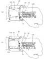
비록 도시되지는 않았지만, 투사부는 광원소자, 영상 형성 모듈 및 렌즈를 포함할 수 있다. 여기에서, 광원소자는 광을 방출하며, 영상 형성 모듈은 광을 이용하여 영상 정보(또는 화면정보)를 형성한다. 렌즈는 영상 정보가 확대 투사되도록 하며, 투사공에 대응하도록 배치될 수 있다. 상기 투사부는, 영사기, 프로젝터(projector), 빔(beam) 또는 빔프로젝터라고 표현되는 것이 가능하다. 이러한, 투사부(156)는, 도 5에 도시된 것과 같이, 이동 단말기 본체(100)의 측면에 배치될 수 있다. 또한, 비록 도시되지는 않았지만, 상기 투사부(156)는 이동 단말기 본체(100)의 임의의 부분에 어디든지 배치될 수 있다.Although not shown, the projection unit may include a light source element, an image forming module, and a lens. Here, the light source element emits light, and the image forming module forms image information (or screen information) using light. The lens allows the image information to be enlarged and projected, and can be arranged to correspond to the projection hole. The projection unit can be expressed as a projector, a projector, a beam, or a beam projector. The
한편, 도 4를 참조하면, 디스플레이부(151) 상에 제1 화면정보가 출력되는 단계가 진행된다(S410). 여기에서, 화면정보는 디스플레이부(151) 상에 출력되는 것이 가능한 그래픽 이미지 또는 GUI(Graphical User Interface)로서, 그 종류에 무관하다. 예를 들어, 디스플레이부(151) 상에 출력되는 제1 화면정보는, 이동 단말기에 설치된 애플리케이션 중 현재 이동 단말기에서 실행되고 있는 애플리케이션의 실행화면일 수 있다.Referring to FIG. 4, the first screen information is output on the display unit 151 (S410). Here, the screen information is a graphical image or GUI (Graphical User Interface) that can be output on the
이와 같이, 디스플레이부(151) 상에 화면정보가 표시되고 있는 상태에서, 디스플레이부에 대하여 터치가 가해지면, 디스플레이부(151)에 구비된 터치 센서 또는 감지부에서 상기 터치를 감지하는 단계가 진행된다(S420).If the touch information is displayed on the
그리고, 상기 감지된 터치가 기 설정된 방식에 대응되는 터치인 경우, 상기 디스플레이부(151)에서 출력되고 있던 제1 화면정보에 대응되는 화면정보가 투사되도록 투사부를 제어하는 단계가 진행된다(S430).If the sensed touch is a touch corresponding to the preset method, a step of controlling the projection unit is performed so that the screen information corresponding to the first screen information being output from the
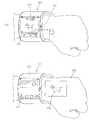
예를 들어, 도 5의 (a)에 도시된 것과 같이, 디스플레이부(151) 상에 제1 화면정보(510)가 표시되고 있는 상태에서, 상기 디스플레이부(151)에 대하여 기 설정된 방식의 터치가 가해지는 경우, 제어부(180)는 도 5의 (b)에 도시된 것과 같이, 상기 제1 화면정보에 대응되는 화면정보(520)가 투사부(156)를 통해 투사되도록 상기 투사부(156)를 제어할 수 있다.For example, as shown in FIG. 5 (a), when the
따라서, 사용자의 손등(501), 손목 또는 기타 다른 물체에는, 상기 제1 화면정보에 대응되는 화면정보(520)가 출력될 수 있다.Accordingly, the
여기에서, 기 설정된 방식의 터치입력은, 디스플레이부의 일 지점에서 상기 투사부(156)가 위치한 방향으로 움직이는, 드래그(drag), 슬라이드(slide) 또는 플리크(flick) 방식의 터치입력일 수 있다. 나아가, 상기 기 설정된 방식의 터치입력은, 상기와 같이, 드래그(drag), 슬라이드(slide) 또는 플리크(flick) 방식의 터치가 기준속도 이상으로 가해지는 터치입력일 수 있다.Here, the predetermined touch input may be a drag, slide, or flick type touch input that moves from one point of the display unit to the direction in which the
또한, 상기 기 설정된 방식의 터치입력은, 디스플레이부(151)의 일 지점에서 시작해서, 디스플레이부(151)를 벗어날때까지 가해지는 드래그(drag), 슬라이드(slide) 또는 플리크(flick) 방식의 터치입력일 수 있다. 이와 같이, 상기 기 설정된 방식의 터치입력은 다양한 방식으로 구현될 수 있다.The touch input of the preset method may be a drag operation, a slide operation, or a flick operation, which is performed from one point on the
한편, 상기 제1 화면정보에 대응되는 화면정보(520)는, 상기 제1 화면정보(510) 자체이거나, 상기 제1 화면정보(510)의 적어도 일부, 상기 제1 화면정보(510)의 요약정보, 또는 상기 제1 화면정보(510)에 대한 메뉴화면일 수 있다. 즉, 상기 제1 화면정보에 대응되는 화면정보(520)는 상기 제1 화면정보(510)와 관련된 정보이기만 하면, 어떤 정보이든 무관할 수 있다.The
한편, 투사부(156)를 통해, 제1 화면정보에 대응되는 화면정보(520)가 투사되는 경우, 디스플레이부(151)에는, 도 5의 (b)에 도시된 것과 같이, 상기 제1 화면정보(510)와 다른 화면정보(530)가 표시될 수 있다. 여기에서, 상기 다른 화면정보(530)는 상기 제1 화면정보(510)가 상기 디스플레이부(151) 상에 출력되기 전 상기 디스플레이부(151)에서 출력되고 있었던 화면정보일 수 있다.On the other hand, when the
또한, 비록 도시되지는 않았지만, 상기 제1 화면정보와 대응되는 화면정보(520)가 상기 제1 화면정보(510)의 요약정보이거나, 상기 제1 화면정보(510)에 대한 메뉴화면인 경우, 상기 디스플레이부(151)에는, 상기 제1 화면정보(510)가 계속하여 출력될 수 있다.Also, although not shown, when the
이와 같이, 투사부(156)를 통해 화면정보(또는 영상 정보)가 투사되는 경우, 디스플레이부(151) 상에 출력되는 화면정보(또는 영상 정보)는 다양하게 변형될 수 있다.In this manner, when screen information (or image information) is projected through the
한편, 투사부(156)를 통해 투사되는 화면정보 또는 영상 정보는, 상기 이동 단말기 본체(100)가 감싸진 영역을 제외한 손목 또는 손등에 표시될 수 있는데, 제어부(180)는 상기 손목 또는 손등의 면적에 따라, 상기 제1 화면정보에 대응되는 화면정보(520)의 표시크기가 달라지도록 상기 투사부(156)를 제어할 수 있다.On the other hand, the screen information or the image information projected through the
이상에서 살펴본 것과 같이, 본 발명에 따른 이동 단말기에서는, 투사부를 통해, 화면정보를 추가적으로 출력시킴으로써, 손목에 감싸는 디스플레이부의 공간적인 제약을 해소할 수 있다.As described above, in the mobile terminal according to the present invention, the screen information is additionally outputted through the projection unit, thereby making it possible to solve the spatial limitation of the display unit which wraps around the wrist.
이하에서는, 디스플레이부에 대한 터치에 대응하여 투사부를 통해 화면정보(또는 영상 정보)를 출력시키는 방법에 대하여 첨부된 도면과 함께 보다 구체적으로 살펴본다. 도 6a, 도 6b, 도 6c, 도 6d, 도 6e 및 도 6f는 본 발명에 따른 이동 단말기에서 프로젝터를 이용하여 정보를 표시하는 방법을 설명하기 위한 개념도이다.Hereinafter, a method of outputting screen information (or image information) through a projection unit in response to a touch to a display unit will be described in detail with reference to the accompanying drawings. 6A, 6B, 6C, 6D, 6E, and 6F are conceptual diagrams illustrating a method of displaying information using a projector in a mobile terminal according to the present invention.
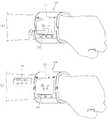
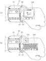
먼저, 도 6a에 도시된 것과 같이, 본 발명의 일 실시 예에 따른 이동 단말기는, 투사부(156)를 포함하고, 이러한 투사부(156)는 적어도 하나의 투사수단(156a, 156b, 156c, 156d)를 포함할 수 있다.6A, a mobile terminal according to an exemplary embodiment of the present invention includes a
즉, 본 발명의 일 실시 예에 따른 이동 단말기에서는, 복수개의 투사수단(156a, 156b, 156c, 156d)을 통해 각각 화면정보(또는 영상 정보)를 출력할 수 있다.That is, in the mobile terminal according to an exemplary embodiment of the present invention, screen information (or image information) can be output through the plurality of
한편, 복수개의 투사수단(156a, 156b, 156c, 156d) 중 어느 것을 통해 화면정보를 출력시킬지 여부는, 디스플레이부(151)에 가해지는 터치의 방향에 따라 결정될 수 있다. 즉, 디스플레이부(151)에 출력된 제1 화면정보에 대응되는 화면정보는, 상기 복수개의 투사수단 중 상기 디스플레이부(151)에 대해 터치가 가해지는 방향과 대응되는 곳에 위치한 투사수단를 통해 투사될 수 있다.Whether or not to output the screen information through the plurality of
예를 들어, 도 6b의 (a)에 도시된 것과 같이, 디스플레이부(151) 상에 제1 화면정보(510)가 출력된 상태에서, 상기 디스플레이부(151)의 일 지점에서 시작한 터치가 제1 투사수단(156a)이 위치한 쪽으로 연속하여 가해지는 경우, 제어부(180)는 도 6b의 (b)에 도시된 것과 같이, 상기 제1 투사수단(156a)을 통해 상기 제1 화면정보에 대응되는 화면정보(520)가 출력되도록 상기 제1 투사수단(156a)을 제어할 수 있다.For example, as shown in (a) of FIG. 6, in a state in which the
그리고, 도 6c의 (a)에 도시된 것과 같이, 디스플레이부(151) 상에 제1 화면정보(510)가 출력된 상태에서, 상기 디스플레이부(151)의 일 지점에서 시작한 터치가 제2 투사수단(156b)이 위치한 쪽으로 연속하여 가해지는 경우, 제어부(180)는 도 6c의 (b)에 도시된 것과 같이, 상기 제2 투사수단(156b)을 통해 상기 제1 화면정보에 대응되는 화면정보(530)가 출력되도록 상기 제2 투사수단(156b)을 제어할 수 있다.6C, when the
또한, 도 6d의 (a)에 도시된 것과 같이, 제1 투사수단(156a)을 통해 화면정보가 표시되고 있던 중, 디스플레이부(151)에 대하여 상기 제2 투사수단(156b)을 통해 화면정보(또는 영상 정보)가 투사되도록 하는 터치가 가해진 경우, 제어부(180)는 도 6d의 (b)에 도시된 것과 같이, 제1 투사수단(156a)을 통해 투사되고 있는 화면정보(520)를 유지시키고, 제2 투사수단(156b)을 통해 추가적으로 화면정보(530)를 투사시킬 수 있다.6 (d), while the screen information is being displayed through the
또한, 비록 도시되지는 않았지만, 제1 투사수단(156a)을 통해 화면정보가 표시되고 있던 중, 디스플레이부(151)에 대하여 상기 제1 투사수단(156b)을 통해 화면정보(또는 영상 정보)가 투사되도록 하는 터치가 다시 가해진 경우, 제어부(180)는 제1 투사수단(156a)을 통해 투사되고 있던 정보대신, 디스플레이부(151)에 서 출력되고 있던 화면정보에 관련된 영상정보를 투사시킬 수 있다.Although not shown, the screen information (or image information) is displayed on the
또한, 비록 도시되지는 않았지만, 제1 투사수단(156a)을 통해 화면정보가 표시되고 있던 중, 디스플레이부(151)에 대하여 상기 제1 투사수단(156b)을 통해 화면정보(또는 영상 정보)가 투사되도록 하는 터치가 다시 가해진 경우, 제어부(180)는 제1 투사수단(156a)을 통해 투사되고 있던 정보와 함께, 디스플레이부(151)에 서 출력되고 있던 화면정보에 관련된 영상정보를 투사시킬 수 있다.Although not shown, the screen information (or image information) is displayed on the
한편, 제어부(180)는 복수개의 투사수단 중 어느 투사수단으로 화면정보가 투사되는지 여부에 따라, 화면정보가 표시되는 형식을 다르게 제어할 수 있다.On the other hand, the
예를 들어, 도 6b에서 살펴본 것과 같이, 제1 투사수단(156a)을 통해서는, 디스플레이부(151)에서 출력되고 있던 제1 화면정보 자체가 투사될 수 있다. 그리고, 도 6e의 (a)에 도시된 것과 같이, 제2 투사수단(156b)을 통해 화면정보가 투사되도록 하는 터치가 상기 디스플레이부(151)에 대해 가해지는 경우, 제어부(180)는 도 6e의 (b)에 도시된 것과 같이, 디스플레이부(151)에서 출력되고 있던 제1 화면정보(510)의 요약정보(530)를 상기 제2 투사수단(156b)을 통해 투사시킬 수 있다For example, as shown in FIG. 6B, the first screen information itself output from the
이와 같이, 제어부(180)는 디스플레이부(151)에 대하여 터치가 가해지는 방향에 따라, 디스플레이부에 출력된 화면정보와 관련된 화면정보가 투사되는 형식이 달라지도록 상기 투사부를 제어할 수 있다.In this way, the
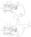
한편, 다른 예로서, 본 발명의 일 실시 예에 따른 이동 단말기에서는, 도 6f의 (a)에 도시된 것과 같이, 복수개의 투사수단(156a, 156b)을 통해 디스플레이부(151) 상에서 출력되고 있는 화면정보(510)를 도 6f의 (b)에 도시된 것과 같이 확대하여 출력할 수 있다.On the other hand, as another example, in the mobile terminal according to the embodiment of the present invention, as shown in (a) of FIG. 6f, a plurality of
즉, 제어부(180)는 디스플레이부(151) 상에 상기 화면정보(510)의 일부를 표시하고, 상기 복수개의 투사수단(156a, 156b)을 통해 상기 화면정보(510)의 다른 일부를 각각 투사시킴으로써, 디스플레이부(151)에서 출력되던 영상을 확대하여 표시할 수 있다.That is, the
이상에서 살펴본 것과 같이, 본 발명의 일 실시 예에 따른 이동 단말기에서는, 디스플레이부에 대한 터치방향에 따라, 복수개의 투사수단 중 어느 것을 통해 영상 정보를 투사시킬지를 결정함으로써, 사용자는 직관적으로 영상을 투사시킬 수사수단을 선택할 수 있다.
As described above, in the mobile terminal according to one embodiment of the present invention, the user determines whether to project the image information through the plurality of projection means according to the touch direction with respect to the display unit, You can select the means of investigation to project.
이하에서는, 이벤트가 수신되는 경우, 투사수단을 통해 정보를 투사하는 방법에 대하여 첨부된 도면과 함께 보다 구체적으로 살펴본다. 도 7a 및 도 7b는 본 발명에 따른 이동 단말기에서 이벤트가 수신되는 경우 정보를 표시하는 방법을 설명하기 위한 개념도이다.Hereinafter, a method of projecting information through a projection unit when an event is received will be described in more detail with reference to the accompanying drawings. 7A and 7B are conceptual diagrams illustrating a method of displaying information when an event is received in a mobile terminal according to the present invention.
먼저, 도 7a의 (a)에 도시된 것과 같이, 본 발명의 일 실시 예에 따른 이동 단말기에서는, 제1 화면정보(510)가 표시되던 중, 이벤트가 수신 또는 발생되는 경우, 상기 제1 화면정보(510)와 함께 이벤트 정보(520)를 출력시킬 수 있다.7A, in the mobile terminal according to an exemplary embodiment of the present invention, when an event is received or generated while the
여기에서, '이벤트'는 단말기에 설치된 적어도 하나의 애플리케이션의 동작에 영향을 미치는 일이 발생하거나, 상기 적어도 하나의 애플리케이션과 관련된 데이터베이스(또는 데이터 파일)의 항목을 변경시키는 일이 발생하거나, 상기 적어도 하나의 애플리케이션을 통하여 외부 단말기 또는 외부 네트워크와 데이터를 전송 또는 송신하는 일이 발생하는 것을 의미한다. 예를 들어, '콜(call) 수신' 또는 '메시지(message) 수신' 등이 상기 이벤트의 일 예가 될 수 있다.Herein, the 'event' refers to an event that affects the operation of at least one application installed in the terminal, or a change of an item of a database (or a data file) related to the at least one application occurs, It means that data is transmitted or transmitted to an external terminal or an external network through one application. For example, 'call reception' or 'message reception' may be an example of the event.
이와 같이, 제1 화면정보(510)와 함께 이벤트 정보(520)가 표시되고 있는 상태에서, 앞서 살펴본 것과 같이, 디스플레이부(151)에 대하여 기 설정된 방식에 대응되는 터치가 가해지는 경우, 제어부(180)는 도 7a의 (b)에 도시된 것과 같이, 상기 제1 화면정보(510)를 투사부(156)를 통해 투사시키고, 이벤트 정보에 대응되는 제2 화면정보(530)를 디스플레이부(151) 상에 출력시킬 수 있다. 따라서, 사용자는, 투사부(156) 및 디스플레이부(151)를 통해 출력되는 영상 정보를 통해, 이벤트와 관련된 제2 화면정보(520) 및 이벤트가 수신되기 전 디스플레이부(151)에서 출력되고 있었던 제1 화면정보(510)를 함께 이용할 수 있다.As described above, when a touch corresponding to a preset method is applied to the
한편, 도 7a의 (a)에 도시된 것과 같이, 이벤트가 수신된 경우, 이벤트가 수신되었음을 알리는 이벤트 정보(520)는 제1 화면정보(510)와 오버랩되어 표시될 수 있다. 그리고, 도 7b의 (b)에 도시된 것과 같이, 제1 화면정보(510)가 투사부(156)를 통해 투사되는 경우, 디스플레이부(151)에는 이벤트에 대응되는 제2 화면정보(520)가 전체적으로 표시될 수 있다.7A, when the event is received, the
한편, 제어부(180)는 상기 제1 화면정보(510)가 표시된 영역에 대하여 상기 터치가 가해지는 경우에만, 디스플레이부(151)에서 출력되고 있던 제1 화면정보(또는 제1 화면정보에 대응되는 화면정보)를 상기 투사부를 통해 출력시킬 수 있다. 즉, 제어부(180)는 도 7b의 (a)에 도시된 것과 같이, 상기 터치가 상기 제1 화면정보(510)가 표시된 영역이 아닌, 이벤트 정보(520)가 표시된 영역에 가해지는 경우, 도 7b의 (b)에 도시된 것과 같이, 상기 이벤트에 대응되는 제2 화면정보(530)를 투사부(156)를 통해 투사시킬 수 있다.On the other hand, when the touch is applied to the area in which the
이상에서 살펴본 것과 같이, 본 발명의 일 실시 예에 따른 이동 단말기에서는, 이벤트가 수신되더라도, 투사부를 통해 이벤트 정보 또는 디스플레이부에서 출력되고 있던 화면정보를 출력시킬 수 있다. 따라서, 사용자는, 서로 다른 화면정보를 동시에 제공받을 수 있다.
As described above, in the mobile terminal according to an exemplary embodiment of the present invention, even if an event is received, the event information or the screen information output from the display unit can be output through the projection unit. Therefore, the user can receive different screen information at the same time.
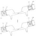
이하에서는, 투사부를 통해 출력된 복수개의 화면정보에 대응되는 기능을 서로 연관시켜 처리하는 방법에 대하여 첨부된 도면과 함께 보다 구체적으로 살펴본다. 도 8a, 도 8b 및 도 8c는 본 발명에 따른 이동 단말기에서 투사부를 통해 출력된 정보를 서로 연관시켜 처리하는 방법을 설명하기 위한 개념도이다.Hereinafter, a method of processing functions corresponding to a plurality of pieces of screen information output through the projection unit in association with each other will be described in detail with reference to the accompanying drawings. 8A, 8B, and 8C are conceptual diagrams illustrating a method of associating and outputting information output through a projection unit in a mobile terminal according to the present invention.
본 발명의 일 실시 예에 따른 이동 단말기에서는, 도 8a에 도시된 것과 같이, 투사부(156)를 통해, 복수개의 화면정보가 출력될 수 있다.In the mobile terminal according to the embodiment of the present invention, as shown in FIG. 8A, a plurality of pieces of screen information can be output through the
예를 들어, 제어부(180)는 도 8a에 도시된 것과 같이, 서로 다른 기능(또는 서로 다른 애플리케이션)에 각각 대응되는 제1 및 제2 화면정보(610, 620)를 출력시킬 수 있다. 예를 들어, 제1 화면정보(610)는 전화(call) 기능에 대응되는 화면정보이고, 제2 화면정보(620)는 갤러리 애플리케이션에 대응되는 화면정보일 수 있다. 이와 같이, 복수개의 화면정보가 출력된 상태에서, 도 8b에 도시된 것과 같이, 어느 하나의 화면정보(예를 들어, 제2 화면정보(620))가 다른 하나의 화면정보(예를 들어, 제1 화면정보(610))로 이동되는 경우, 제어부(180)는 도 8c에 도시된 것과 같이, 상기 제1 화면정보(610) 및 제2 화면정보(620)에 대응되는 기능을 서로 연관시켜 처리할 수 있다.For example, the
예를 들어, 갤러리 애플리케이션에 대응되는 제2 화면정보(620)가 전화 기능에 대응되는 화면정보(610)로 드래그된 경우, 제어부(180)는 상기 제2 화면정보(620)에 대응되는 이미지(image)를 본 발명에 따른 이동 단말기와 통화를 수행하는 다른 단말기로 전송시킬 수 있다. 즉, 제어부(180)는 제2 화면정보(620)가 전화 기능에 대응되는 화면정보(610)로 드래그되는 것에 응답하여, 수신측(또는 발신측) 단말기로 이미지를 전송시킬 수 있다. 이 경우, 도 8c에 도시된 것과 같이, 제어부(180)는 연관된 기능이 수행되고 있는 상태(예를 들어, 이미지 전송 상태)에 대한 정보가 상기 제1 화면정보(610) 및 제2 화면정보(620) 중 적어도 하나에 출력되도록 상기 투사부(156)를 제어할 수 있다.
For example, when the
이하에서는, 투사부를 통해 복수의 화면정보를 표시하는 방법에 대하여 첨부된 도면과 함께 보다 구체적으로 살펴본다. 도 9a, 도 9b, 도 9c 및 도 9d는 본 발명에 따른 이동 단말기에서 복수의 화면정보를 표시하는 방법을 설명하기 위한 개념도이다.Hereinafter, a method of displaying a plurality of screen information through the projection unit will be described in detail with reference to the accompanying drawings. 9A, 9B, 9C, and 9D are conceptual diagrams for explaining a method of displaying a plurality of screen information in the mobile terminal according to the present invention.
본 발명의 일 실시 예에 따른 이동 단말기에서는, 디스플레이부(151)에 출력된 정보 중 적어도 일부 또는 상기 적어도 일부에 대응되는 상세정보를 사용자의 선택에 근거하여 투사부(156)를 통해 투사시킬 수 있다.In the mobile terminal according to an exemplary embodiment of the present invention, at least part of the information output to the
예를 들어, 도 9a에 도시된 것과 같이, 디스플레이부(151) 상에 복수개의 썸네일(thumbnail)이 표시되어 있고, 상기 썸네일 중 어느 하나(711)가 표시된 영역에 대하여 기 설정된 방식의 터치가 가해지는 경우, 제어부(180)는 도 9b에 도시된 것과 같이, 상기 어느 하나의 썸네일에 대응되는 이미지(720)를 투사부(156)를 통해 투사시킬 수 있다. 따라서, 사용자는, 디스플레이부(151)을 통해 복수개의 썸네일을 이용하는 것과 동시에, 필요에 따라 투사부(156)에 의한 투사를 통해 상기 복수개의 썸네일 중 적어도 하나에 대한 이미지를 자세하게 확인할 수 있다.For example, as shown in FIG. 9A, a plurality of thumbnails are displayed on the
한편, 도 9b, 도 9c 및 도 9d에 도시된 것과 같이, 제어부(180)는 디스플레이부(151)에 출력된 다른 썸네일들에 대한 기 설정된 방식의 터치에 근거하여, 상기 썸네일들에 각각 대응되는 이미지를 투사시킬 수 있다. 따라서, 사용자의 손목에는, 도 9c 및 도 9d에 도시된 것과 같이, 복수개의 이미지(721, 722, 723)를 순차적으로 표시할 수 있다. 한편, 복수개의 이미지(721, 722, 723)가 배치되는 순서는, 상기 터치가 가해진 순서에 종속될 수 있다. 또한, 투사부(156)를 통해 투사된 이미지들(721, 722, 723)의 배치순서는 사용자의 선택에 근거하여 변경되는 것이 가능하다.
9B, 9C, and 9D, the
이하에서는, 사용자의 제스처에 근거하여 투사부에 의해 영상 정보가 투사되는 것을 종료시키는 방법에 대하여 첨부된 도면과 함께 보다 구체적으로 살펴본다. 도 10a, 도 10b, 도 10c 및 도 10d는 본 발명에 따른 이동 단말기에서 투사부를 통해 출력된 정보를 제어하는 방법을 설명하기 위한 개념도이다.Hereinafter, a method for terminating the projection of image information by the projection unit based on the gesture of the user will be described in more detail with reference to the accompanying drawings. 10A, 10B, 10C, and 10D are conceptual diagrams illustrating a method of controlling information output through a projection unit in a mobile terminal according to the present invention.
본 발명의 일 실시 예에 따른 이동 단말기에서는, 도 10a의 (a)에 도시된 것과 같이, 투사부(156)를 통해 화면 정보(510)가 손등 또는 손목에 투사되고 있는 상태에서, 도 10a의 (b)에 도시된 것과 같이, 손등이 아래로 움직이는 것과 같은 기 설정된 제스처(gesture)가 감지되면, 상기 투사되고 있던 화면 정보(510)의 투사를 종료시킬 수 있다.In the mobile terminal according to the embodiment of the present invention, as shown in FIG. 10A, when the
본 발명의 일 실시 예에 따른 이동 단말기에서는 본체(100)가 손목과 접촉하는 면에 센싱부(140)를 배치시킴으로써, 손목을 지나는 복수개의 힘줄들의 움직임이 상기 센싱부(140)를 통해 센싱되도록 할 수 있다. 이 경우, 상기 센싱부(140)는 손가락 또는 손목의 움직임 검출부의 역할을 수행할 수 있다. 즉, 상기 센싱부(140)는 손가락의 움직임에 따른 힘줄들의 움직임을 센싱하고, 센싱된 정보를 제어부(180)에 전달할 수 있다. 또한, 제어부(180)는 센싱부(140)로부터 센싱된 정보를 기반으로, 상기 손가락 또는 손목의 움직임에 매칭된 기능을 처리할 수 있다.In the mobile terminal according to an embodiment of the present invention, the
한편, 손가락의 움직임에 따른 힘줄들의 움직임에 대하여 살펴보면, 손목 내부의 수근관(또는 손목굴, carpal tunnel)에는 각각의 손가락 움직임을 관장하는 힘줄들의 힘줄 다발(finger flexor tendons)이 존재한다. 상기 힘줄 다발에는 아홉 개의 힘줄과 한개의 신경이 존재하며, 손가락이 움직이는 경우, 상기 힘줄 다발에 포함된 아홉 개의 힘줄들이 다양한 조합으로 움직인다. 센싱부(140)는 손가락 또는 손목의 움직임에 따라 변형된 힘줄들의 형상을 센싱하고, 제어부(180)는 센싱된 정보를 기초로 손가락들이 어떤 제스처를 취하고 있는지 판단할 수 있다.On the other hand, as for the movement of the tendons according to the movement of the fingers, finger flexor tendons are present in the carpal tunnel (or the carpal tunnel) inside the wrist. There are nine tendons and one nerve in the tendon bundle. When the finger moves, nine tendons contained in the tendon bundle move in various combinations. The
따라서, 제어부(180)는 센싱부(140)를 통해, 손가락 또는 손목의 움직임이 기 설정된 제스처에 대응되는 경우, 상기 기 설정된 제스처에 매칭된 기능을 실행할 수 있다. 즉, 도 10a에 도시된 것과 같이, "투사 종료 기능"이 "손목을 꺾는 제스처"에 매칭되어 있는 경우, 제어부(180)는 상기 "손목을 꺾는 제스처"에 대응되는 기능을 실행할 수 있다. 한편, "손목을 꺾는 제스처"는 일 예에 불과하며, "투사 종료 기능"에 대응되는 제스처는 다양할 수 있다.Accordingly, when the movement of the finger or the wrist corresponds to the preset gesture, the
한편, 도 10b의 (a)에 도시된 것과 같이, 복수개의 화면정보(510, 520)가 투사되고 있는 상태에서, 복수개의 화면정보(510, 520)가 표시된 영역과 대응되는 손가락(511)에 대하여 충격이 가해지는 경우, 도 10b의 (b)에 도시된 것과 같이, 상기 충격이 가해진 손가락(511)과 대응되는 위치에 표시된 화면정보(510)의 투사가 종료될 수 있다. 한편, 상기 손가락(511)에 대하여 충격이 가해졌는지 여부는, 앞서 살펴본 것과 같이, 센싱부(140)에 의해 감지될 수 있다.On the other hand, as shown in FIG. 10B, when a plurality of pieces of
또한, 본 발명의 일 실시 예에 따른 이동 단말기에서는, 어느 손가락에 대하여 충격을 가하는 경우 어느 화면정보의 투사가 종료되는지에 대한 정보를 사용자에게 주기 위하여, 도 10c에 도시된 것과 같이, 가이드 정보(531, 532)를 함께 출력시킬 수 있다.In addition, in the mobile terminal according to the embodiment of the present invention, in order to give the user information about which projection of the screen information ends when the impact is applied to which finger, as shown in FIG. 10C, 531, and 532 can be output together.
한편, 본 발명의 일 실시 예에 따른 이동 단말기에서, 제어부(180)는 도 10d의 (a)에 도시된 것과 같이, 투사된 화면정보(510)의 일 지점에 대한 터치가 기 설정된 방식에 대응되는 경우, 도 10d의 (b)에 도시된 것과 같이, 투사된 화면정보(510)의 투사를 종료시킬 수 있다. 여기에서, 상기 기 설정된 방식의 터치는, 상기 투사된 화면정보(510)의 일 지점에서 시작해서 이동 단말기 본체(100)로 향하는 드래그 터치일 수 있다.Meanwhile, in the mobile terminal according to the embodiment of the present invention, as shown in (a) of FIG. 10d, the
이상에서 살펴본 것과 같이, 본 발명의 일 실시 예에 따른 이동 단말기에서는 손목 또는 손가락을 이용한 직관적인 제스처를 통해, 투사된 화면정보를 제어함으로써, 사용자 편의를 향상시킬 수 있다.
As described above, in the mobile terminal according to an exemplary embodiment of the present invention, user's convenience can be improved by controlling the projected screen information through an intuitive gesture using a wrist or a finger.
이하에서는, 제스처를 통해 정보를 전송하는 방법에 대하여 첨부된 도면과 함께 보다 구체적으로 살펴본다. 도 11a, 도 11b, 도 12a, 도 12b 및 도 12c는 본 발명에 따른 이동 단말기에서 정보를 전송하는 방법을 설명하기 위한 개념도이다.Hereinafter, a method of transmitting information through a gesture will be described in detail with reference to the accompanying drawings. 11A, 11B, 12A, 12B and 12C are conceptual diagrams illustrating a method of transmitting information in a mobile terminal according to the present invention.
본 발명의 일 실시 예에 따른 이동 단말기에서는, 손가락 또는 손목의 제스처가 기 설정된 움직임에 대응되는 경우, 투사된 화면정보에 대응되는 데이터를 적어도 하나의 외부 단말기 또는 외부 서버로 전송시킬 수 있다. 한편, 데이터를 전송받을 외부 단말기 또는 외부 서버를 특정하는 방법은 매우 다양할 수 있으며 본 명세서에는 이에 대한 구체적인 설명을 생략한다.In the mobile terminal according to an exemplary embodiment of the present invention, when the gesture of the finger or the wrist corresponds to a preset movement, data corresponding to the projected screen information may be transmitted to at least one external terminal or an external server. Meanwhile, a method for specifying an external terminal or an external server to which data is to be transmitted may vary, and a detailed description thereof will be omitted herein.
일 예로서, 도 11a의 (a)에 도시된 것과 같이, 투사부(156)를 통해 화면 정보(510, 520)가 손등 또는 손목에 투사되고 있는 상태에서, 도 11a의 (b)에 도시된 것과 같이, 어느 하나의 손가락(511)이 펼쳐지는 경우, 제어부(180)는 펼쳐진 손가락과 대응되는 위치에 표시된 화면정보(510)를 기 설정된 적어도 하나의 외부 단말기 또는 외부 서버로 전송시킬 수 있다. 한편, 상기 손가락(511)이 펼쳐졌는지 여부는 앞서 살펴본 것과 같이, 센싱부(140)에 의해 감지될 수 있다.11A, in a state in which the
또한, 본 발명의 일 실시 예에 따른 이동 단말기에서는, 어느 손가락에 대하여 충격을 가하는 경우 어느 화면정보의 투사가 종료되는지에 대한 정보를 사용자에게 주기 위하여, 도 11b에 도시된 것과 같이, 가이드 정보(531, 532)를 함께 출력시킬 수 있다.In addition, in the mobile terminal according to the embodiment of the present invention, in order to give the user information as to which screen information is to be projected when a shock is applied to a finger, as shown in FIG. 11B, 531, and 532 can be output together.
또한, 본 발명의 일 실시 예에 따른 이동 단말기에서는, 생체신호가 인식되는 것에 근거하여, 투사된 화면정보 또는 디스플레이부(151)에 출력된 화면정보 중 적어도 하나에 대응되는 데이터를 상기 인식된 생체신호(biomedical signal)에 따른 상대방 이동 단말기로 전송시킬 수 있다.In the mobile terminal according to an embodiment of the present invention, data corresponding to at least one of the projected screen information or the screen information output to the
즉, 도 12a에 도시된 것과 같이, 본 발명에 따른 이동 단말기(100)의 사용자의 손가락이, 다른 사용자의 손가락과 접촉하는 경우, 본 발명에 따른 이동 단말기에는 상기 접촉에 근거하여, 생체신호가 수신될 수 있다. 제어부(180)는 이러한 생체신호가 수신되는 것 자체를, "디스플레이부(151) 또는 투사된 화면정보 중 적어도 하나에 대응되는 데이터를 전송"하라는 제어명령으로 인식할 수 있다. 따라서, 제어부(180)는 도 12a의 (b)에 도시된 것과 같이, 상기 생체신호가 발생되도록 한 다른 사용자의 이동 단말기(100b)에 투사된 화면정보 또는 디스플레이부(151)에 출력된 화면정보 중 적어도 하나에 대응되는 데이터를 전송시킬 수 있다.12A, when the user's finger of the
한편, 본 발명에 따른 이동 단말기에서는, 상기 생체신호가 수신되고 나아가, 디스플레이부(151)에 대하여 기 설정된 방식의 터치가 가해지는 경우에 한하여, 투사된 화면정보 또는 디스플레이부(151)에 출력된 화면정보 중 적어도 하나에 대응되는 데이터를 전송시킬 수 있다.On the other hand, in the mobile terminal according to the present invention, only when the biometric signal is received and a predetermined type of touch is applied to the
한편, 본 발명에 따른 이동 단말기에서는, 사용자와 다른 사용자가 접촉한 정도에 따라서 데이터가 전송되는 정도를 다르게 할 수 있다. 즉, 제어부(180)는 수신되는 생체신호의 정도에 따라, 데이터 전송 양이 달라지도록, 무선 통신부(110)를 제어할 수 있다. 예를 들어,도 12b에 도시된 것과 같이, 사용자가 다른 사용자와 악수를 하는 경우와, 도 12c에 도시된 것과 같이, 사용자와 다른 사용자가 포옹을 하는 경우에, 전송되는 데이터의 양은 각각 다를 수 있다. 즉, 도 12b에 도시된 것과 같이, 사용자가 다른 사용자와 악수를 하는 경우에는, 세 개의 이미지 데이터가 전송될 수 있고, 도 12c에 도시된 것과 같이, 사용자가 다른 사용자가 포옹을 하는 경우에는, 아홉 개의 이미지 데이터가 전송될 수 있다.Meanwhile, in the mobile terminal according to the present invention, it is possible to vary the degree of data transmission depending on the degree of contact between the user and another user. That is, the
한편, 본 발명에 따른 이동 단말기에서는, 사용자가 다른 사용자가 악수를 하고, 나아가, 악수한 손이 기 설정된 횟수 및 속도 중 적어도 하나에 대응되도록 움직이는 경우, 즉 쉐이킹(shaking)되는 경우에만, 데이터를 전송시킬 수 있다.On the other hand, in the mobile terminal according to the present invention, only when a user shakes hands by another user and further moves the shaking hand to correspond to at least one of a predetermined number of times and a speed, that is, shaking, Can be transmitted.
이상에서 살펴본 것과 같이, 본 발명의 일 실시 예에 따른 이동 단말기에서는, 손목 또는 손가락을 이용한 제스처 또는 생체신호와 같이, 데이터 전송을 위한 제어명령을 직관적인 방법으로 생성함으로써, 사용자 편의를 향상시킬 수 있다.As described above, in the mobile terminal according to an embodiment of the present invention, a control command for data transmission, such as a gesture using a wrist or a finger or a biometric signal, is generated in an intuitive manner, have.
이하에서는, IR(infraed ray)을 통해 투사되는, 버추얼 보다를 통해, 사용자로부터 정보를 입력받는 방법에 대하여 첨부된 도면과 함께 보다 구체적으로 살펴본다. 도 13a, 도 13b, 도 13c 및 도 13d는 본 발명에 따른 이동 단말기에서 가상 키보드를 출력하는 방법을 설명하기 위한 개념도이다.Hereinafter, a method of inputting information from a user through virtual reality, which is projected through IR (infraed ray), will be described in detail with reference to the accompanying drawings. 13A, 13B, 13C, and 13D are conceptual diagrams for explaining a method of outputting a virtual keyboard in a mobile terminal according to the present invention.
본 발명의 일 실시 예에 따른 이동 단말기에서, 투사부는, 앞서 살펴본 것과 같이, 광원소자, 영상 형성 모듈 및 렌즈를 포함할 수 있다. 여기에서, 광원소자는 광을 방출하며, 영상 형성 모듈은 광을 이용하여 영상 정보(또는 화면정보)를 형성할 수 있다.In the mobile terminal according to an exemplary embodiment of the present invention, the projection unit may include a light source device, an image forming module, and a lens, as described above. Here, the light source element emits light, and the image forming module can form image information (or screen information) using light.
나아가, 본원발명에서 이러한 투사부는, 특히, 레이저 다이오드(Laser Diode)를 포함할 수 있으며, 이러한 레이저 다이오드(Laser Diode)는 특히, 레드 레이저 다이오드(Red Laser Diode)로 구성될 수 있다.Furthermore, in the present invention, the projection unit may include a laser diode, and the laser diode may be a red laser diode.
도 13a에 도시되 것과 같이, 본 발명에 따른 이동 단말기는, 앞서 살펴본 것과 같이, 영상을 출력하기 위한 제1 투사부(156) 및 레이저 다이오드로 구성된 제2 투사부(157)를 모두 구비할 수 있다. 또한, 비록 도시되지는 않았지만, 본 발명에 따른 이동 단말기는, 영상을 출력하기 위한 제1 투사부(156)는 구비하지 않고, 제2 투사부(157) 만을 별도로 구비하는 것 또한 가능하다.As shown in FIG. 13A, the mobile terminal according to the present invention may include both a
본 발명의 일 실시 예에 따른 제어부(180)에서는, 상기 제2 투사부(157)에서 투사되는 빛, 예를 들어, 가시광선을 이용하여, 사용자의 손등(501), 손목 또는 기타 다른 물체에 가상 키보드(virtual keyboard)를 출력시킬 수 있다.The
한편, 본 발명의 일 실시 예에 따른 이동 단말기에서는, 제2 투사부(157)가 활성화된 상태에서는, 항상 가상 키보드가 출력될 수 있도록, 상기 제2 투사부(157)를 제어할 수 있다. 이를 위해, 본 발명에 따른 이동 단말기에서는, 제2 투사부(157)를 활성화 시키기 위한 사용자 입력부(131)를 별도로 구비할 수 있다. 이러한, 사용자 입력부(151)는 물리적인 버튼(button)으로 구성되거나, 터치패드고 구성될 수 있다. 한편, 비록 도시되지는 않았지만, 본 발명의 일 실시 예에 따른 이동 단말기에서는, 제2 투사부(157)를 활성화시키기 위한 사용자 입력부(131)를 별도로 구비하지 않은 경우라도, 디스플레이부(151)를 통한 터치입력을 통해, 제2 투사부(157)를 활성화시킬 수 있다. 또한, 본 발명의 일 실시 예에 따른 이동 단말기에서는, 제2 투사부(157)를 활성화시키기 위한 사용자 입력부(131)가 별도로 구비된 경우라도, 디스플레이부(151)를 통한 터치입력을 통해, 제2 투사부(157)를 활성화시키는 것이 가능하다.Meanwhile, in the mobile terminal according to the embodiment of the present invention, the
사용자 입력부(131)가 구비된 실시 예에 대하여 살펴보면, 도 13b의 (a)에 도시된 것과 같이, 사용자 입력부(131)가 사용자에 의해 가압 또는 터치되면, 제어부(180)는 도 13b의 (b)에 도시된 것과 같이, 가상 키보드(1320)를 출력시킬 수 있다. 나아가, 제어부(180)는, 도 13b의 (b)에 도시된 것과 같이, 가상 키보드(1320)에 대한 근접 또는 인접터치가 가해지는 경우, 터치가 가해진 영역에 출력된 키(key)에 대응하는 문자가 선택된 것으로 판단할 수 있다. 예를 들어, 제어부(180)는 적외선 센서(미도시됨)를 이용하여, 가상 키보드(1320)에 포함된 복수개의 키(key) 중 어느 키(key)가 선택되었는지를 판단할 수 있다.When the
한편, 위와 같이, 선택된 문자는 도시된 것과 같이, 디스플레이부(151) 상에 출력될 수 있다. 따라서, 사용자는, 디스플레이부(151)를 이용하여, 정보를 입력하지 않고, 가상 키보드(1320)를 이용하여, 정보를 입력하는 것이 가능하다. 이와 같이, 본 발명의 일 실시 예에 따른 이동 단말기에서는, 디스플레이부(151)의 크기가 제한적인 시계형 이동 단말기의 단점을 극복할 수 있다.On the other hand, as described above, the selected character may be output on the
한편, 본 발명에 따른 이동 단말기에서는, 도 13c의 (a)에 도시된 것과 같이, 제1 투사부(156)를 통해, 화면정보(1330)가 투사되고 있던 중, 제2 투사부(157)를 활성화 시키는 제어명령이 생성된 경우, 도 13c의 (b)에 도시된 것과 같이, 사용자가 제1 및 제2 투사부(156, 157)를 통해 투사되는 영상을 모두 이용할 수 있도록, 제1 투사부(156)를 통해 투사되던 화면정보(1330)를 축소하여, 축소된 화면정보(1331)를 출력시킬 수 있다. 축소된 화면정보(1331)는 축소되기 전 화면정보(1330)를 그대로 축소시킨 화면정보이거나, 축소되기 전 화면정보(1330)의 요약정보일 수 있다. 여기서, 요약정보는, 축소되기 전 화면정보(1330)를 대표하는 정보일 수 있다.On the other hand, in the mobile terminal according to the present invention, while the
한편, 제어부(180)는 영상이 투사될 공간이 확보된 경우에는, 제1 투사부(156)를 통해 투사되던 화면정보를 축소시키지 않을 수 있다. 즉, 제어부(180)는 영상이 투사된 공간의 크기에 따라, 제1 투사부(156)를 통해 투사되는 화면정보의 축소여부, 축소정도를 결정할 수 있다.On the other hand, when the space in which the image is to be projected is secured, the
또한, 제어부(180)는, 영상이 투사될 공간의 크기에 따라, 제2 투사부(157)를 통해 출력되는 가상 키보드의 크기 또한, 조절하는 것이 가능하다.In addition, the
한편, 본 발명에 따른 이동 단말기에서는, 도 13d의 (a)에 도시된 것과 같이, 제1 투사부(156a)를 통해, 화면정보(1330)가 투사되고 있던 중, 제2 투사부(157)를 활성화 시키는 제어명령이 생성된 경우, 도 13d의 (b)에 도시된 것과 같이, 제2 투사부(157)와 같은 방향에 배치된, 제1 투사부(156a)를 통해 화면정보(1330)를 투사시키는 것을 중단시키고, 제2 투사부(157)와 다른 방향에 배치된 제3 투사부(156b)통해 화면정보(1350)를 투사시킬 수 있다.On the other hand, in the mobile terminal according to the present invention, as shown in (a) of FIG. 13D, while the
이상에서 살펴본 것과 같이, 본 발명의 일 실시 예에 따른 이동 단말기에서는, 투사부를 통해 가상 키보드를 출력시킴으로써, 디스플레이부(151)의 크기가 제한적인 시계형 이동 단말기의 단점을 극복할 수 있다.As described above, in the mobile terminal according to the embodiment of the present invention, the virtual keyboard is outputted through the projection unit, thereby overcoming the disadvantage of the watch type mobile terminal having the limited size of the
또한, 본 발명의 일 실시 예에 따른 이동 단말기에서는, 본체에 구비되는 디스플레이부 외에, 투사부를 추가적으로 구비하고, 이러한 투사부를 통해 사용자의 손목 또는 손등에 정보를 출력할 수 있다. 따라서, 사용자는, 디스플레이부 및 투사부를 통해서 보다 다양하고, 많은 양의 화면정보를 제공받을 수 있다.In addition, a mobile terminal according to an embodiment of the present invention may further include a projection unit in addition to a display unit provided in the main body, and may output information to a wrist or a hand of a user through the projection unit. Accordingly, the user can receive more various and larger amounts of screen information through the display unit and the projection unit.
또한, 본 발명의 일 실시 예에 따른 이동 단말기는, 손목의 움직임과 같은 제스처에 근거하여 디스플레이부 또는 투사부에서 출력되는 정보의 상태를 변경시킬 수 있다. 따라서, 사용자는 직관적으로 이동 단말기를 통해 출력되는 정보를 제어하는 것이 가능하다. 결과적으로, 사용자의 편의가 향상될 수 있다.In addition, the mobile terminal according to the embodiment of the present invention can change the state of the information output from the display unit or the projection unit based on the gesture such as the movement of the wrist. Therefore, the user can intuitively control the information output through the mobile terminal. As a result, the convenience of the user can be improved.
또한, 본 명세서에 개시된 일 실시 예에 의하면, 전술한 방법은, 프로그램이 기록된 매체에 프로세서가 읽을 수 있는 코드로서 구현하는 것이 가능하다. 프로세서가 읽을 수 있는 매체의 예로는, ROM, RAM, CD-ROM, 자기 테이프, 플로피 디스크, 광 데이터 저장장치 등이 있으며, 캐리어 웨이브(예를 들어, 인터넷을 통한 전송)의 형태로 구현되는 것도 포함한다.Further, according to the embodiment disclosed herein, the above-described method can be implemented as a code that can be read by a processor on a medium on which the program is recorded. Examples of the medium that can be read by the processor include ROM, RAM, CD-ROM, magnetic tape, floppy disk, optical data storage, etc., and may be implemented in the form of a carrier wave (e.g., transmission over the Internet) .
상기와 같이 설명된 이동 단말기는 상기 설명된 실시 예들의 구성과 방법이 한정되게 적용될 수 있는 것이 아니라, 상기 실시 예들은 다양한 변형이 이루어질 수 있도록 각 실시 예들의 전부 또는 일부가 선택적으로 조합되어 구성될 수도 있다.The mobile terminal described above can be applied to not only the configuration and method of the embodiments described above but also all or some of the embodiments may be selectively combined so that various modifications may be made to the embodiments It is possible.
Claims (18)
Translated fromKorean상기 본체의 측면에 배치되고, 영상 정보를 투사하는 투사부;
상기 본체의 전면에 배치되고, 제1 화면정보를 출력하도록 형성되는 디스플레이부; 및
상기 디스플레이부에 대해 기 설정된 방식의 터치가 가해지는 것에 근거하여, 상기 디스플레이부에서 출력되고 있던 상기 제1 화면정보에 대응되는 화면정보가 투사되도록 상기 투사부를 제어하는 제어부를 포함하는 것을 특징으로 하는 이동 단말기.A body formed to surround at least one region of the wrist;
A projection unit disposed on a side surface of the main body and projecting image information;
A display unit disposed on a front surface of the main body and configured to output first screen information; And
And a control unit for controlling the projection unit so that screen information corresponding to the first screen information output from the display unit is projected on the basis of a touch of a predetermined type to the display unit. Mobile terminal.
이벤트가 수신되는 경우, 수신된 이벤트와 관련된 이벤트 정보를 상기 제1 화면정보와 함께 상기 디스플레이부 상에 출력하고,
상기 터치가 가해지는 경우, 상기 제1 화면정보에 대응되는 화면정보를 상기 투사부를 통해 투사시키고, 상기 이벤트 정보에 대응되는 제2 화면정보를 상기 디스플레이부 상에 출력시키는 것을 특징으로 하는 이동 단말기.The apparatus of claim 1, wherein the control unit
When the event is received, outputs event information related to the received event on the display unit together with the first screen information,
And projecting screen information corresponding to the first screen information through the projection unit when the touch is applied, and outputting second screen information corresponding to the event information on the display unit.
상기 이벤트 정보는 상기 제1 화면정보에 오버랩되어 표시되고, 상기 제2 화면정보는 상기 디스플레이부 상에 전체적으로 표시되는 것을 특징으로 하는 이동 단말기.3. The method of claim 2,
Wherein the event information is displayed so as to overlap with the first screen information, and the second screen information is displayed entirely on the display unit.
상기 제1 화면정보가 표시된 영역에 대하여 상기 터치가 가해지는 경우에만, 상기 제1 화면정보에 대응되는 화면정보를 상기 투사부를 통해 출력시키는 것을 특징으로 하는 이동 단말기.3. The apparatus of claim 2, wherein the control unit
And outputs the screen information corresponding to the first screen information through the projection unit only when the touch is applied to the area in which the first screen information is displayed.
상기 이벤트 정보가 출력된 영역에 대하여 상기 터치가 가해지는 경우, 상기 제2 화면정보를 상기 투사부를 통해 투사시키고, 상기 디스플레이부 상에 상기 제1 화면정보를 계속하여 출력시키는 것을 특징으로 하는 이동 단말기.5. The apparatus of claim 4, wherein the control unit
When the touch is applied to the area where the event information is output, projecting the second screen information through the projection unit, and continuously outputting the first screen information on the display unit .
상기 제1 화면정보에 대응되는 화면정보가 상기 투사부를 통해 투사되는 경우,
상기 디스플레이부 상에는, 상기 제1 화면정보가 표시되기 전, 상기 디스플레이부 상에서 출력되고 있었던 제2 화면정보가 다시 출력되는 것을 특징으로 하는 이동 단말기.The method according to claim 1,
When the screen information corresponding to the first screen information is projected through the projection unit,
Wherein the second screen information outputted on the display unit is output again on the display unit before the first screen information is displayed.
상기 제1 화면정보에 대응되는 화면정보는, 상기 제1 화면정보 자체이거나, 상기 제1 화면정보의 요약정보인 것을 특징으로 하는 이동 단말기.The method according to claim 6,
Wherein the screen information corresponding to the first screen information is the first screen information itself or the summary information of the first screen information.
상기 투사부는 복수개의 투사수단를 포함하고,
상기 제1 화면정보에 대응되는 화면정보는, 상기 복수개의 투사수단 중 상기 터치가 가해지는 방향과 대응되는 곳에 위치한 투사수단를 통해 투사되는 것을 특징으로 하는 이동 단말기.The method according to claim 1,
Wherein the projection unit includes a plurality of projection units,
Wherein the screen information corresponding to the first screen information is projected through a projection unit located at a position corresponding to a direction in which the touch is applied among the plurality of projection units.
상기 터치가 가해지는 방향에 따라, 상기 제1 화면정보에 대응되는 화면정보가 투사되는 형식이 달라지도록 상기 투사부를 제어하는 것을 특징으로 하는 이동 단말기.9. The apparatus of claim 8, wherein the control unit
Wherein the control unit controls the projection unit so that a form in which screen information corresponding to the first screen information is projected is changed according to a direction in which the touch is applied.
상기 터치가 제1 방향으로 가해지면, 상기 제1 화면정보와 대응되는 화면정보는, 상기 복수개의 투사수단 중 제1 투사수단을 통해 출력되고,
상기 터치가 상기 제1 방향과 다른 제2 방향으로 가해지면, 상기 제1 화면정보와 대응되는 화면정보는 상기 복수개의 투사수단 중 상기 제1 투사수단과 다른 제2 투사수단을 통해 출력되며,
상기 제1 투사수단을 통해 투사되는 상기 제1 화면정보와 대응되는 화면정보는, 상기 제1 화면정보의 요약정보이고,
상기 제2 투사수단을 통해 투사되는 상기 대응되는 화면정보는, 상기 제1 화면정보 자체인 것을 특징으로 하는 이동 단말기.10. The method of claim 9,
When the touch is applied in the first direction, the screen information corresponding to the first screen information is outputted through the first projection means of the plurality of projection means,
When the touch is applied in a second direction different from the first direction, the screen information corresponding to the first screen information is outputted through the second projection means different from the first projection means among the plurality of projection means,
The screen information corresponding to the first screen information projected through the first projection means is the summary information of the first screen information,
Wherein the corresponding screen information projected through the second projection means is the first screen information itself.
상기 투사부를 통해 투사되고 있는 상기 제1 화면정보에 대응되는 화면정보에 대하여, 기 설정된 방식의 터치가 가해지는 것에 응답하여, 상기 디스플레이부 상에 다시 상기 제1 화면정보를 출력시키는 것을 특징으로 하는 이동 단말기.The apparatus of claim 1, wherein the control unit
And outputs the first screen information again on the display unit in response to a predetermined type of touch being applied to the screen information corresponding to the first screen information being projected through the projection unit Mobile terminal.
상기 투사부를 통해 상기 제1 화면정보에 대응되는 화면정보가 투사되는 경우, 상기 디스플레이부 상에는 상기 제1 화면정보와 다른 제2 화면정보가 표시되고,
상기 디스플레이부 상에서 제2 화면정보가 출력되고 있던 중 상기 디스플레이부에 대하여 다시 상기 터치가 가해지면,
상기 제어부는
상기 투사부를 통해 상기 제2 화면정보에 대응되는 화면정보가 상기 제1 화면정보에 대응되는 화면정보와 함께 투사되도록 상기 투사부를 제어하는 것을 특징으로 하는 이동 단말기.The method according to claim 1,
When the screen information corresponding to the first screen information is projected through the projection unit, second screen information different from the first screen information is displayed on the display unit,
When the second touch information is being output to the display unit,
The control unit
And controls the projection unit to project the screen information corresponding to the second screen information together with the screen information corresponding to the first screen information through the projection unit.
상기 제2 화면정보에 대응되는 화면정보 및 상기 제1 화면정보에 대응되는 화면정보 중 어느 하나가 다른 하나로 드래그되는 것에 응답하여, 상기 제1 및 제2 화면정보에 각각 대응되는 기능을 서로 연관시켜 처리하는 것을 특징으로 하는 이동 단말기.13. The apparatus of claim 12, wherein the control unit
In response to one of the screen information corresponding to the second screen information and the screen information corresponding to the first screen information being dragged to another one of the plurality of functions, the functions corresponding to the first and second screen information are associated with each other And processes the received signal.
상기 투사부를 통해 투사되는 화면정보는, 상기 본체가 감싸진 영역을 제외한 손목 또는 손등에 표시되고,
상기 제어부는, 상기 손목 또는 손등의 면적에 따라 상기 제1 화면정보와 대응되는 화면정보의 표시크기가 달라지도록 상기 투사부를 제어하는 것을 특징으로 하는 이동 단말기.The method according to claim 1,
The screen information projected through the projection unit is displayed on a wrist or a hand except for the area enclosed by the main body,
Wherein the control unit controls the projection unit such that the display size of the screen information corresponding to the first screen information is changed according to the area of the wrist or the hand.
상기 제1 화면정보와 대응되는 화면정보가 손등에 출력된 경우, 상기 손등이 굽혀지는 것이 감지되는 응답하여, 상기 제1 화면정보와 대응되는 화면정보의 투사가 종료되도록 상기 투사부를 제어하는 것을 특징으로 하는 이동 단말기.The apparatus of claim 1, wherein the control unit
And controlling the projection unit so that projection of the screen information corresponding to the first screen information is terminated in response to detecting that the back of the hand is detected when the screen information corresponding to the first screen information is output to the back of the hand .
상기 기 설정된 방식의 터치가 핀치-인 터치인 경우,
상기 제1 화면정보가 상기 투사부 및 상기 디스플레이부를 통해 확대되어 표시되는 것을 특징으로 하는 이동 단말기.The method according to claim 1,
When the touch of the preset method is a pinch-in touch,
Wherein the first screen information is enlarged and displayed through the projection unit and the display unit.
상기 본체의 전면에 배치되는 디스플레이부를 통해 제1 화면정보를 출력시키는 단계;
상기 디스플레이부에 대해 기 설정된 방식의 터치를 감지하는 단계; 및
상기 터치가 감지되는 것에 응답하여, 상기 디스플레이부에서 출력되고 있던 상기 제1 화면정보에 대응되는 화면정보를 상기 투사부를 통해 투사시키고, 상기 디스플레이부 상에 상기 제1 화면정보와 다른 제2 화면정보를 출력시키는 단계를 포함하는 것을 특징으로 하는 이동 단말기의 제어방법.A control method for a mobile terminal including a main body and a projection unit disposed on a side surface of the main body,
Outputting first screen information through a display unit disposed on a front surface of the main body;
Sensing a predetermined type of touch on the display unit; And
In response to the touch being sensed, projecting screen information corresponding to the first screen information output from the display unit through the projection unit and displaying second screen information different from the first screen information on the display unit And outputting the control signal to the mobile terminal.
이벤트가 수신되는 경우, 상기 디스플레이부 상에는 상기 제1 화면정보와 함께 상기 수신된 이벤트와 관련된 이벤트 정보가 출력되고,
상기 터치가 가해지는 경우, 상기 제1 화면정보에 대응되는 화면정보는 상기 투사부를 통해 투사되고, 상기 이벤트 정보에 대응되는 제2 화면정보는 상기 디스플레이부 상에 출력되는 것을 특징으로 하는 이동 단말기의 제어방법.18. The method of claim 17,
When the event is received, event information related to the received event is output on the display unit together with the first screen information,
Wherein the screen information corresponding to the first screen information is projected through the projection unit and the second screen information corresponding to the event information is output on the display unit when the touch is applied. Control method.
Priority Applications (2)
| Application Number | Priority Date | Filing Date | Title |
|---|---|---|---|
| KR1020130057889AKR101999958B1 (en) | 2013-05-22 | 2013-05-22 | Mobile terminal and control method thereof |
| US14/280,449US9651991B2 (en) | 2013-05-22 | 2014-05-16 | Mobile terminal and control method thereof |
Applications Claiming Priority (1)
| Application Number | Priority Date | Filing Date | Title |
|---|---|---|---|
| KR1020130057889AKR101999958B1 (en) | 2013-05-22 | 2013-05-22 | Mobile terminal and control method thereof |
Publications (2)
| Publication Number | Publication Date |
|---|---|
| KR20140137227A KR20140137227A (en) | 2014-12-02 |
| KR101999958B1true KR101999958B1 (en) | 2019-07-15 |
Family
ID=51935057
Family Applications (1)
| Application Number | Title | Priority Date | Filing Date |
|---|---|---|---|
| KR1020130057889ACeasedKR101999958B1 (en) | 2013-05-22 | 2013-05-22 | Mobile terminal and control method thereof |
Country Status (2)
| Country | Link |
|---|---|
| US (1) | US9651991B2 (en) |
| KR (1) | KR101999958B1 (en) |
Families Citing this family (54)
| Publication number | Priority date | Publication date | Assignee | Title |
|---|---|---|---|---|
| US9100493B1 (en)* | 2011-07-18 | 2015-08-04 | Andrew H B Zhou | Wearable personal digital device for facilitating mobile device payments and personal use |
| JP2015041052A (en)* | 2013-08-23 | 2015-03-02 | ソニー株式会社 | Wristband type information processing apparatus and storage medium |
| KR101534282B1 (en)* | 2014-05-07 | 2015-07-03 | 삼성전자주식회사 | User input method of portable device and the portable device enabling the method |
| CN106687885B (en)* | 2014-05-15 | 2020-03-03 | 联邦快递公司 | Wearable device for messenger processing and method of use thereof |
| US9575560B2 (en) | 2014-06-03 | 2017-02-21 | Google Inc. | Radar-based gesture-recognition through a wearable device |
| EP2957983A1 (en)* | 2014-06-18 | 2015-12-23 | Alcatel Lucent | User-wearable electronic device and system for personal computing |
| US9921660B2 (en) | 2014-08-07 | 2018-03-20 | Google Llc | Radar-based gesture recognition |
| US9811164B2 (en) | 2014-08-07 | 2017-11-07 | Google Inc. | Radar-based gesture sensing and data transmission |
| US9588625B2 (en) | 2014-08-15 | 2017-03-07 | Google Inc. | Interactive textiles |
| US10268321B2 (en) | 2014-08-15 | 2019-04-23 | Google Llc | Interactive textiles within hard objects |
| US9778749B2 (en) | 2014-08-22 | 2017-10-03 | Google Inc. | Occluded gesture recognition |
| US11169988B2 (en) | 2014-08-22 | 2021-11-09 | Google Llc | Radar recognition-aided search |
| KR20160029390A (en)* | 2014-09-05 | 2016-03-15 | 삼성전자주식회사 | Portable terminal and control method for the same |
| US9830783B1 (en) | 2014-09-24 | 2017-11-28 | Apple Inc. | Output devices for fabric-based electronic equipment |
| US9600080B2 (en) | 2014-10-02 | 2017-03-21 | Google Inc. | Non-line-of-sight radar-based gesture recognition |
| KR101632007B1 (en) | 2014-10-29 | 2016-06-21 | 엘지전자 주식회사 | Watch type control device |
| WO2016080565A1 (en)* | 2014-11-18 | 2016-05-26 | 엘지전자 주식회사 | Wearable device and control method therefor |
| US9798355B2 (en)* | 2014-12-02 | 2017-10-24 | Lenovo (Beijing) Co., Ltd. | Projection method and electronic device |
| CN104461001B (en)* | 2014-12-02 | 2018-02-27 | 联想(北京)有限公司 | A kind of information processing method and electronic equipment |
| KR20160085613A (en)* | 2015-01-08 | 2016-07-18 | 엘지전자 주식회사 | Mobile terminal and method for controlling the same |
| CN105988609B (en)* | 2015-01-28 | 2019-06-04 | 中强光电股份有限公司 | Touch control type projection screen and manufacturing method thereof |
| TWI553536B (en) | 2015-03-13 | 2016-10-11 | 中強光電股份有限公司 | Touch projection screen and touch projection system |
| US10016162B1 (en) | 2015-03-23 | 2018-07-10 | Google Llc | In-ear health monitoring |
| US9983747B2 (en) | 2015-03-26 | 2018-05-29 | Google Llc | Two-layer interactive textiles |
| FR3034889B1 (en)* | 2015-04-10 | 2017-04-28 | Cn2P Sas | ELECTRONIC BRACELET FOR DISPLAYING AN INTERACTIVE DIGITAL CONTENT TO BE PROJECTED ON A ZONE OF AN ARM |
| KR102229658B1 (en) | 2015-04-30 | 2021-03-17 | 구글 엘엘씨 | Type-agnostic rf signal representations |
| EP3885882A1 (en) | 2015-04-30 | 2021-09-29 | Google LLC | Rf-based micro-motion tracking for gesture tracking and recognition |
| CN111880650B (en) | 2015-04-30 | 2024-07-05 | 谷歌有限责任公司 | Gesture recognition based on wide-field radar |
| US9693592B2 (en) | 2015-05-27 | 2017-07-04 | Google Inc. | Attaching electronic components to interactive textiles |
| US10088908B1 (en) | 2015-05-27 | 2018-10-02 | Google Llc | Gesture detection and interactions |
| US10817065B1 (en) | 2015-10-06 | 2020-10-27 | Google Llc | Gesture recognition using multiple antenna |
| US20170115737A1 (en)* | 2015-10-26 | 2017-04-27 | Lenovo (Singapore) Pte. Ltd. | Gesture control using depth data |
| WO2017079484A1 (en) | 2015-11-04 | 2017-05-11 | Google Inc. | Connectors for connecting electronics embedded in garments to external devices |
| KR102568710B1 (en) | 2016-03-30 | 2023-08-21 | 삼성전자주식회사 | Electronic device and operating method thereof |
| WO2017192167A1 (en) | 2016-05-03 | 2017-11-09 | Google Llc | Connecting an electronic component to an interactive textile |
| WO2017200570A1 (en) | 2016-05-16 | 2017-11-23 | Google Llc | Interactive object with multiple electronics modules |
| JP2019537094A (en)* | 2016-09-30 | 2019-12-19 | 深▲セン▼市柔宇科技有限公司Shenzhen Royole Technologies Co.,Ltd. | Electronic equipment |
| US10579150B2 (en) | 2016-12-05 | 2020-03-03 | Google Llc | Concurrent detection of absolute distance and relative movement for sensing action gestures |
| KR102408359B1 (en)* | 2017-08-23 | 2022-06-14 | 삼성전자주식회사 | Electronic device and method for controlling using the electronic device |
| CN107682541B (en)* | 2017-09-27 | 2021-02-05 | 努比亚技术有限公司 | Audio control method for screen projection, mobile terminal and storage medium |
| US11188154B2 (en)* | 2018-05-30 | 2021-11-30 | International Business Machines Corporation | Context dependent projection of holographic objects |
| US10802598B2 (en)* | 2018-08-05 | 2020-10-13 | Pison Technology, Inc. | User interface control of responsive devices |
| US11099647B2 (en)* | 2018-08-05 | 2021-08-24 | Pison Technology, Inc. | User interface control of responsive devices |
| CN110147199A (en)* | 2019-05-23 | 2019-08-20 | 北京硬壳科技有限公司 | Display on the same screen method, apparatus and touch control display |
| CN111078167B (en)* | 2019-11-12 | 2023-08-22 | 博泰车联网科技(上海)股份有限公司 | Information transmission method, vehicle, computer storage medium and information transmission system |
| CN111131866B (en) | 2019-11-25 | 2021-06-15 | 华为技术有限公司 | A kind of screen projection audio and video playback method and electronic device |
| CN111093066A (en)* | 2019-12-03 | 2020-05-01 | 耀灵人工智能(浙江)有限公司 | Dynamic plane projection method and system |
| US11157086B2 (en) | 2020-01-28 | 2021-10-26 | Pison Technology, Inc. | Determining a geographical location based on human gestures |
| US11199908B2 (en) | 2020-01-28 | 2021-12-14 | Pison Technology, Inc. | Wrist-worn device-based inputs for an operating system |
| CN111506214A (en)* | 2020-03-23 | 2020-08-07 | 上海博泰悦臻电子设备制造有限公司 | Vehicle-mounted projection implementation method and device |
| US11221690B2 (en) | 2020-05-20 | 2022-01-11 | Micron Technology, Inc. | Virtual peripherals for mobile devices |
| US12340627B2 (en) | 2022-09-26 | 2025-06-24 | Pison Technology, Inc. | System and methods for gesture inference using computer vision |
| US12366920B2 (en) | 2022-09-26 | 2025-07-22 | Pison Technology, Inc. | Systems and methods for gesture inference using transformations |
| US12366923B2 (en) | 2022-09-26 | 2025-07-22 | Pison Technology, Inc. | Systems and methods for gesture inference using ML model selection |
Citations (3)
| Publication number | Priority date | Publication date | Assignee | Title |
|---|---|---|---|---|
| US20100099457A1 (en) | 2008-10-16 | 2010-04-22 | Lg Electronics Inc. | Mobile communication terminal and power saving method thereof |
| US20110151926A1 (en) | 2009-12-17 | 2011-06-23 | Samsung Electronics Co. Ltd. | Method and system for controlling output of a mobile device |
| US20120249409A1 (en) | 2011-03-31 | 2012-10-04 | Nokia Corporation | Method and apparatus for providing user interfaces |
Family Cites Families (4)
| Publication number | Priority date | Publication date | Assignee | Title |
|---|---|---|---|---|
| WO2010024028A1 (en)* | 2008-08-29 | 2010-03-04 | 日本電気株式会社 | Position information input device and position information input method |
| KR20110044424A (en)* | 2009-10-23 | 2011-04-29 | 엘지전자 주식회사 | Mobile terminal and its control method |
| KR20110071349A (en)* | 2009-12-21 | 2011-06-29 | 삼성전자주식회사 | External output control method and device of mobile terminal |
| US8954878B2 (en)* | 2012-09-04 | 2015-02-10 | Google Inc. | Information navigation on electronic devices |
- 2013
- 2013-05-22KRKR1020130057889Apatent/KR101999958B1/ennot_activeCeased
- 2014
- 2014-05-16USUS14/280,449patent/US9651991B2/ennot_activeExpired - Fee Related
Patent Citations (3)
| Publication number | Priority date | Publication date | Assignee | Title |
|---|---|---|---|---|
| US20100099457A1 (en) | 2008-10-16 | 2010-04-22 | Lg Electronics Inc. | Mobile communication terminal and power saving method thereof |
| US20110151926A1 (en) | 2009-12-17 | 2011-06-23 | Samsung Electronics Co. Ltd. | Method and system for controlling output of a mobile device |
| US20120249409A1 (en) | 2011-03-31 | 2012-10-04 | Nokia Corporation | Method and apparatus for providing user interfaces |
Also Published As
| Publication number | Publication date |
|---|---|
| US9651991B2 (en) | 2017-05-16 |
| US20140347295A1 (en) | 2014-11-27 |
| KR20140137227A (en) | 2014-12-02 |
Similar Documents
| Publication | Publication Date | Title |
|---|---|---|
| KR101999958B1 (en) | Mobile terminal and control method thereof | |
| KR101474467B1 (en) | Mobile terminal and control method for the mobile terminal | |
| KR20140126186A (en) | Mobile terminal and control method thereof | |
| KR101549867B1 (en) | Mobile terminal and method for controlling the same | |
| KR20140096893A (en) | Mobile terminal and cover for the same | |
| KR20140128724A (en) | Mobile terminal and control method thereof | |
| KR20150026338A (en) | Mobile terminal | |
| KR20150032054A (en) | Mobile terminal and control method for the mobile terminal | |
| KR20150056504A (en) | Mobile terminal and method of controlling the mobile terminal | |
| KR101984098B1 (en) | Mobile terminal and icon arranging method thereof | |
| KR20150064561A (en) | Mobile terminal and cover for the same | |
| KR102157143B1 (en) | Mobile terminal and control method thereof | |
| KR20150138171A (en) | Mobile terminal and method for controlling the same | |
| KR20150009008A (en) | Mobile terminal and control method thereof | |
| KR20150056356A (en) | Mobile terminal and method of controlling the same | |
| KR20140125630A (en) | Control apparatus of mobile terminal and method thereof | |
| KR20140096894A (en) | Inputtun devuce and mobile terminal conrtolled by the inputting device | |
| KR101977089B1 (en) | Mobile terminal and method of controlling the same | |
| KR20140102936A (en) | Mobile terminal and control method thereof | |
| KR20140085039A (en) | Control apparatus of mobile terminal and method thereof | |
| KR20140141300A (en) | Watch type terminal and control method thereof | |
| KR20150044296A (en) | Watch type mobile terminal and control method thereof | |
| KR20150032056A (en) | Wearable glass-type device and metohd of coltrolling the device | |
| KR20150009488A (en) | Mobile terminal and control method for the mobile terminal | |
| KR20140102937A (en) | Mobile terminal and method for controlling the same |
Legal Events
| Date | Code | Title | Description |
|---|---|---|---|
| PA0109 | Patent application | Patent event code:PA01091R01D Comment text:Patent Application Patent event date:20130522 | |
| PG1501 | Laying open of application | ||
| A201 | Request for examination | ||
| PA0201 | Request for examination | Patent event code:PA02012R01D Patent event date:20180314 Comment text:Request for Examination of Application Patent event code:PA02011R01I Patent event date:20130522 Comment text:Patent Application | |
| E701 | Decision to grant or registration of patent right | ||
| PE0701 | Decision of registration | Patent event code:PE07011S01D Comment text:Decision to Grant Registration Patent event date:20190419 | |
| GRNT | Written decision to grant | ||
| PR0701 | Registration of establishment | Comment text:Registration of Establishment Patent event date:20190709 Patent event code:PR07011E01D | |
| PR1002 | Payment of registration fee | Payment date:20190710 End annual number:3 Start annual number:1 | |
| PG1601 | Publication of registration | ||
| PC2102 | Extinguishment | Termination category:Others Termination date:20210625 |