KR101998091B1 - Apparatus for measuring current using shunt resistor - Google Patents
Apparatus for measuring current using shunt resistorDownload PDFInfo
- Publication number
- KR101998091B1 KR101998091B1KR1020160097245AKR20160097245AKR101998091B1KR 101998091 B1KR101998091 B1KR 101998091B1KR 1020160097245 AKR1020160097245 AKR 1020160097245AKR 20160097245 AKR20160097245 AKR 20160097245AKR 101998091 B1KR101998091 B1KR 101998091B1
- Authority
- KR
- South Korea
- Prior art keywords
- shunt resistor
- terminal
- module
- current
- measuring
- Prior art date
- Legal status (The legal status is an assumption and is not a legal conclusion. Google has not performed a legal analysis and makes no representation as to the accuracy of the status listed.)
- Active
Links
Images


Classifications
- G—PHYSICS
- G01—MEASURING; TESTING
- G01R—MEASURING ELECTRIC VARIABLES; MEASURING MAGNETIC VARIABLES
- G01R31/00—Arrangements for testing electric properties; Arrangements for locating electric faults; Arrangements for electrical testing characterised by what is being tested not provided for elsewhere
- G01R31/36—Arrangements for testing, measuring or monitoring the electrical condition of accumulators or electric batteries, e.g. capacity or state of charge [SoC]
- G01R31/382—Arrangements for monitoring battery or accumulator variables, e.g. SoC
- G01R31/3842—Arrangements for monitoring battery or accumulator variables, e.g. SoC combining voltage and current measurements
- G—PHYSICS
- G01—MEASURING; TESTING
- G01R—MEASURING ELECTRIC VARIABLES; MEASURING MAGNETIC VARIABLES
- G01R1/00—Details of instruments or arrangements of the types included in groups G01R5/00 - G01R13/00 and G01R31/00
- G01R1/20—Modifications of basic electric elements for use in electric measuring instruments; Structural combinations of such elements with such instruments
- G01R1/203—Resistors used for electric measuring, e.g. decade resistors standards, resistors for comparators, series resistors, shunts
- G—PHYSICS
- G01—MEASURING; TESTING
- G01R—MEASURING ELECTRIC VARIABLES; MEASURING MAGNETIC VARIABLES
- G01R1/00—Details of instruments or arrangements of the types included in groups G01R5/00 - G01R13/00 and G01R31/00
- G01R1/20—Modifications of basic electric elements for use in electric measuring instruments; Structural combinations of such elements with such instruments
- G—PHYSICS
- G01—MEASURING; TESTING
- G01R—MEASURING ELECTRIC VARIABLES; MEASURING MAGNETIC VARIABLES
- G01R15/00—Details of measuring arrangements of the types provided for in groups G01R17/00 - G01R29/00, G01R33/00 - G01R33/26 or G01R35/00
- G01R15/14—Adaptations providing voltage or current isolation, e.g. for high-voltage or high-current networks
- G01R15/146—Measuring arrangements for current not covered by other subgroups of G01R15/14, e.g. using current dividers, shunts, or measuring a voltage drop
- G—PHYSICS
- G01—MEASURING; TESTING
- G01R—MEASURING ELECTRIC VARIABLES; MEASURING MAGNETIC VARIABLES
- G01R19/00—Arrangements for measuring currents or voltages or for indicating presence or sign thereof
- G01R19/165—Indicating that current or voltage is either above or below a predetermined value or within or outside a predetermined range of values
- G01R19/16533—Indicating that current or voltage is either above or below a predetermined value or within or outside a predetermined range of values characterised by the application
- G01R19/16538—Indicating that current or voltage is either above or below a predetermined value or within or outside a predetermined range of values characterised by the application in AC or DC supplies
- G01R19/16542—Indicating that current or voltage is either above or below a predetermined value or within or outside a predetermined range of values characterised by the application in AC or DC supplies for batteries
- G—PHYSICS
- G01—MEASURING; TESTING
- G01R—MEASURING ELECTRIC VARIABLES; MEASURING MAGNETIC VARIABLES
- G01R31/00—Arrangements for testing electric properties; Arrangements for locating electric faults; Arrangements for electrical testing characterised by what is being tested not provided for elsewhere
- G01R31/36—Arrangements for testing, measuring or monitoring the electrical condition of accumulators or electric batteries, e.g. capacity or state of charge [SoC]
- G01R31/364—Battery terminal connectors with integrated measuring arrangements
- G—PHYSICS
- G01—MEASURING; TESTING
- G01R—MEASURING ELECTRIC VARIABLES; MEASURING MAGNETIC VARIABLES
- G01R31/00—Arrangements for testing electric properties; Arrangements for locating electric faults; Arrangements for electrical testing characterised by what is being tested not provided for elsewhere
- G01R31/36—Arrangements for testing, measuring or monitoring the electrical condition of accumulators or electric batteries, e.g. capacity or state of charge [SoC]
- G01R31/382—Arrangements for monitoring battery or accumulator variables, e.g. SoC
- G01R31/3835—Arrangements for monitoring battery or accumulator variables, e.g. SoC involving only voltage measurements
- G—PHYSICS
- G01—MEASURING; TESTING
- G01R—MEASURING ELECTRIC VARIABLES; MEASURING MAGNETIC VARIABLES
- G01R31/00—Arrangements for testing electric properties; Arrangements for locating electric faults; Arrangements for electrical testing characterised by what is being tested not provided for elsewhere
- G01R31/36—Arrangements for testing, measuring or monitoring the electrical condition of accumulators or electric batteries, e.g. capacity or state of charge [SoC]
- G01R31/396—Acquisition or processing of data for testing or for monitoring individual cells or groups of cells within a battery
- H—ELECTRICITY
- H01—ELECTRIC ELEMENTS
- H01M—PROCESSES OR MEANS, e.g. BATTERIES, FOR THE DIRECT CONVERSION OF CHEMICAL ENERGY INTO ELECTRICAL ENERGY
- H01M10/00—Secondary cells; Manufacture thereof
- H01M10/42—Methods or arrangements for servicing or maintenance of secondary cells or secondary half-cells
- H01M10/4285—Testing apparatus
- H—ELECTRICITY
- H01—ELECTRIC ELEMENTS
- H01M—PROCESSES OR MEANS, e.g. BATTERIES, FOR THE DIRECT CONVERSION OF CHEMICAL ENERGY INTO ELECTRICAL ENERGY
- H01M10/00—Secondary cells; Manufacture thereof
- H01M10/42—Methods or arrangements for servicing or maintenance of secondary cells or secondary half-cells
- H01M10/48—Accumulators combined with arrangements for measuring, testing or indicating the condition of cells, e.g. the level or density of the electrolyte
- H01M10/482—Accumulators combined with arrangements for measuring, testing or indicating the condition of cells, e.g. the level or density of the electrolyte for several batteries or cells simultaneously or sequentially
- H—ELECTRICITY
- H01—ELECTRIC ELEMENTS
- H01M—PROCESSES OR MEANS, e.g. BATTERIES, FOR THE DIRECT CONVERSION OF CHEMICAL ENERGY INTO ELECTRICAL ENERGY
- H01M50/00—Constructional details or processes of manufacture of the non-active parts of electrochemical cells other than fuel cells, e.g. hybrid cells
- H01M50/50—Current conducting connections for cells or batteries
- H01M50/502—Interconnectors for connecting terminals of adjacent batteries; Interconnectors for connecting cells outside a battery casing
- H01M50/507—Interconnectors for connecting terminals of adjacent batteries; Interconnectors for connecting cells outside a battery casing comprising an arrangement of two or more busbars within a container structure, e.g. busbar modules
- Y—GENERAL TAGGING OF NEW TECHNOLOGICAL DEVELOPMENTS; GENERAL TAGGING OF CROSS-SECTIONAL TECHNOLOGIES SPANNING OVER SEVERAL SECTIONS OF THE IPC; TECHNICAL SUBJECTS COVERED BY FORMER USPC CROSS-REFERENCE ART COLLECTIONS [XRACs] AND DIGESTS
- Y02—TECHNOLOGIES OR APPLICATIONS FOR MITIGATION OR ADAPTATION AGAINST CLIMATE CHANGE
- Y02E—REDUCTION OF GREENHOUSE GAS [GHG] EMISSIONS, RELATED TO ENERGY GENERATION, TRANSMISSION OR DISTRIBUTION
- Y02E60/00—Enabling technologies; Technologies with a potential or indirect contribution to GHG emissions mitigation
- Y02E60/10—Energy storage using batteries
Landscapes
- Physics & Mathematics (AREA)
- General Physics & Mathematics (AREA)
- Chemical & Material Sciences (AREA)
- Chemical Kinetics & Catalysis (AREA)
- Electrochemistry (AREA)
- General Chemical & Material Sciences (AREA)
- Engineering & Computer Science (AREA)
- Manufacturing & Machinery (AREA)
- Power Engineering (AREA)
- Measuring Instrument Details And Bridges, And Automatic Balancing Devices (AREA)
- Secondary Cells (AREA)
Abstract
Translated fromKoreanDescription
Translated fromKorean본 발명은 션트저항을 이용한 전류 측정 장치에 관한 것으로, 하나의 션트(Shunt)저항이 포함된 버스바(Busbar) 두 개 이상을 하나의 버스바 모듈로 일체화 하고, 일체화된 버스바에 포함된 복수 개의 션트저항 양단에 인가되는 전압을 측정함으로써, 배터리 모듈의 전압을 산출하는 션트저항을 이용한 전류 측정 장치에 관한 것이다. The present invention relates to a current measuring apparatus using a shunt resistor, in which two or more bus bars including one shunt resistor are integrated into one bus bar module, and a plurality of bus bars And a current measuring device using a shunt resistor for calculating a voltage of a battery module by measuring a voltage applied to both ends of the shunt resistor.
제품군에 따른 적용 용이성이 높고, 높은 에너지 밀도 등의 전기적 특성을 가지는 이차전지는 휴대용 기기뿐만 아니라 전기적 구동원에 의하여 구동하는 전기차량(EV, Electric Vehicle), 하이브리드 차량(HV, Hybrid Vehicle) 또는 가정용 또는 산업용으로 이용되는 중대형 배터리를 이용하는 에너지 저장 시스템(Energy Storage System; ESS)이나 무정전 전원 공급 장치(Uninterruptible Power Supply; UPS) 시스템 등에 보편적으로 응용되고 있다.Secondary batteries having high electrical properties such as high energy density and high ease of application according to the product group can be used not only as a portable device but also as an electric vehicle (EV), a hybrid vehicle (HV), a hybrid vehicle (ESS) and uninterruptible power supply (UPS) systems using medium to large batteries for industrial use.
이러한 이차 전지는 화석 연료의 사용을 획기적으로 감소시킬 수 있다는 일 장점뿐만 아니라 에너지의 사용에 따른 부산물이 전혀 발생되지 않는다는 점에서친환경 및 에너지 효율성 제고를 위한 새로운 에너지원으로 주목 받고 있다.These secondary batteries are not only advantageous in that they can significantly reduce the use of fossil fuels, but also produce no by-products resulting from the use of energy, and thus are attracting attention as a new energy source for enhancing environmental friendliness and energy efficiency.
2차 전지는 휴대 단말 등의 배터리로 구현되는 경우는 반드시 그러하지 않을 수 있으나, 상기와 같이 전기 차량 또는 에너지 저장원 등에 적용되는 배터리는 통상적으로 단위 이차전지 셀(cell)이 복수 개 집합되는 형태로 사용되어 고용량 환경에 적합성을 높이게 된다.The secondary battery may not necessarily be realized by a battery of a portable terminal or the like. However, as described above, a battery applied to an electric vehicle, an energy storage source, or the like generally has a plurality of unit secondary battery cells Thus increasing the suitability for high capacity environments.
이와 같이 복수 개 집합되는 형태로 사용되는 경우, 과전류가 흐르는 등의 동작 이상이 발생했을 경우 과열에 의하여 단위 셀이 부풀어서 파손되는 등의 문제가 생길 수 있어, 항상 각 개별 셀의 전압, 온도 등의 여러 상태 값들을 측정 및 모니터링 하여 단위 셀에 과충전 또는 과방전이 인가되는 것을 방지해야 한다는 점이 고려되어야 한다.In the case where a plurality of cells are assembled in this manner, when an operation abnormality such as an overcurrent occurs, the unit cell may be inflated and broken due to overheating, and the voltage, temperature, etc. It is necessary to take into account the fact that overcharging or overdischarge is prevented from being applied to the unit cell by measuring and monitoring various status values of the unit cell.
종래에는 이러한 2차 전지 모듈의 전압 및 전류를 측정하고, 이를 통해 과전압 및 과전압 상태를 판단하기 위해서 전압 측정용 션트(Shunt)저항을 버스바(Busbar)와 같은 2차 전지 모듈 및 2차 전지 팩에 포함되는 부품에 설치하고, 이를 통해 측정된 전압값에 기반하여 배터리 모듈의 전류를 산출함으로써, 2차 전지 모듈의 상태를 진단한다. 그러나 신뢰성이 높은 측정값을 얻기 위해 복수 개의 션트저항 및 측정소자를 사용할 경우, 버스바의 개수가 많아지기 때문에 2차 전지 모듈 및 2차 전지 팩의 부피 및 가격이 증가하는 문제점이 있다. 이러한 2차 전지 모듈의 부피 증가는 2차 전지의 고효율화 및 고 에너지 밀도화에 악영향을 끼치게 된다.Conventionally, in order to measure the voltage and current of such a secondary battery module and determine the overvoltage and overvoltage condition, a voltage measuring shunt resistor is connected to a secondary battery module such as a bus bar, And diagnoses the state of the secondary battery module by calculating the current of the battery module based on the measured voltage value. However, when a plurality of shunt resistors and measuring devices are used to obtain a highly reliable measurement value, the number of bus bars increases, and thus the volume and cost of the secondary battery module and the secondary battery pack increase. This increase in the volume of the secondary battery module adversely affects the high efficiency and high energy density of the secondary battery.
따라서 2차 전지의 효율 및 에너지밀도 개선을 위해 2차 전지 모듈의 소형화가 필수적인 만큼, 2차전지의 전압 및 전류 측정의 신뢰도를 향상시키고, 션트저항이 포함된 버스바가 가지고 있는 부피적 및 가격적 단점을 보완해야 할 필요성이 있다.Therefore, miniaturization of the secondary battery module is required to improve the efficiency and energy density of the secondary battery. Therefore, reliability of the voltage and current measurement of the secondary battery is improved, and the volume and cost of the bus bar including the shunt resistor There is a need to compensate for the drawbacks.
본 발명의 일 실시예에 따르면, 신뢰성 높은 전압값을 측정하기 위해 종래의 션트저항이 포함된 버스바 타입의 부품을 복수 개 사용함으로써 발생하는 부피적 및 가격적 단점을 보완하기 위하여, 일체화된 버스바를 이용하여 전압값을 측정할 수 있는 전류 측정 장치 및 방법을 제공한다.According to an embodiment of the present invention, in order to compensate for the volumetric and price disadvantages caused by using a plurality of bus bar type components including a conventional shunt resistor for measuring a reliable voltage value, A current measuring apparatus and method capable of measuring a voltage value using a bar are provided.
또한, 본 발명의 일 실시 예에 따르면, 일체화된 버스바에 포함된 션트저항를 이용하여 전압값을 측정함으로써 배터리 모듈 및 배터리 팩의 부피를 줄이고, 가격을 감소시킬 수 있는 전류 측정 장치 및 방법을 제공한다.According to an embodiment of the present invention, there is provided a current measuring apparatus and method capable of reducing the volume and cost of a battery module and a battery pack by measuring a voltage value using a shunt resistor included in an integrated bus bar .
또한, 본 발명의 일 실시 예에 따르면, 복수 개의 측정부를 통해 복수 개의 션트저항을 각각 측정함으로써, 신뢰성있는 전압값을 측정할 수 있는 션트저항을 이용한 전류 측정 장치를 제공한다.According to an embodiment of the present invention, there is provided a current measuring apparatus using a shunt resistor capable of measuring a reliable voltage value by measuring a plurality of shunt resistances through a plurality of measuring units, respectively.
본 발명의 일 실시예에 따른, 션트저항을 이용한 전류 측정 장치는, 배터리 팩 내에 포함된 두 개의 배터리 모듈의 모듈 단자를 서로 연결하는 하나 이상의 버스바(Busbar); 상기 버스바 상에 위치하며, 상기 버스바를 적어도 두 개 이상의 영역으로 분리시키는 적어도 둘 이상의 션트저항; 및 상기 둘 이상의 션트저항에 인가되는 전압값을 각각 측정하고, 상기 측정된 전압값에 기반하여 전류값을 각각 산출하는 하나 이상의 측정부;를 포함하여 구성될 수 있다.According to an embodiment of the present invention, a current measuring apparatus using a shunt resistor includes: one or more bus bars connecting module terminals of two battery modules included in a battery pack to each other; At least two or more shunt resistors located on the bus bar and separating the bus bar into at least two regions; And at least one measuring unit for measuring a voltage value applied to the at least two shunt resistors and calculating a current value based on the measured voltage value, respectively.
상기 측정부는, 상기 션트저항에 인가되는 전압값을 증폭하는 전압 증폭부; 및 상기 증폭된 전압값에 기반하여 상기 배터리 모듈의 전류값을 산출하는 전류 산출부;를 포함할 수 있다.Wherein the measuring unit comprises: a voltage amplifying unit amplifying a voltage value applied to the shunt resistor; And a current calculator calculating a current value of the battery module based on the amplified voltage value.
상기 하나 이상의 측정부는, 하나의 측정 모듈로 구성되며, 상기 측정 모듈은, 상기 하나 이상의 측정부의 동작을 제어할 수 있는 제어부;를 포함할 수 있다.The at least one measuring unit may comprise one measuring module, and the measuring module may include a controller capable of controlling the operation of the at least one measuring unit.
상기 션트저항을 이용한 전류 측정 장치는 적어도 일부 영역에 관통홀을 가지는 단자 션트저항; 및 상기 단자 션트저항 양단에 인가되는 전압값을 측정하기 위한 제1 접속 단자 및 제2 접속 단자;를 더 포함하며, 상기 단자 션트저항을 상기 제 1 및 제2 접속 단자로 사이에 두어 상기 모듈 단자를 상기 관통홀에 삽입해 설치할 수 있다.The current measuring device using the shunt resistor includes: a terminal shunt resistor having a through hole in at least a part of the region; And a first connection terminal and a second connection terminal for measuring a voltage value applied across the terminal shunt resistor, wherein the terminal shunt resistor is interposed between the first and second connection terminals, Can be inserted into the through hole.
상기 단자 션트저항은 와셔 형태, 상기 모듈 단자는 볼트 형태이며, 상기 와셔 형태 션트저항 내부에 형성된 관통홀을 볼트 형태 모듈 단자에 나사 결합하여 상기 단자 션트저항과 상기 모듈 단자를 전기적으로 연결할 수 있다.The terminal shunt resistor may be in the form of a washer, the module terminal may be in the form of a bolt, and a through hole formed in the washer type shunt resistor may be screwed to the bolt type module terminal to electrically connect the terminal shunt resistor and the module terminal.
본 발명의 일 실시예에 따른, 션트저항을 이용한 전류 측정 장치는, 배터리 팩 내에 포함된 두 개의 배터리 모듈의 모듈 단자를 서로 연결하는 하나 이상의 버스바(Busbar); 상기 버스바 상에 위치하며, 상기 버스바를 두 개의 영역으로 분리시키는 션트저항; 및 상기 션트저항에 포함된 세 개 이상의 노드 중 적어도 두 개의 노드를 선택하여 상기 선택된 두 개의 노드 사이에 인가되는 전압값을 기반으로, 상기 배터리 모듈의 전류값을 측정하는 하나 이상의 측정부;를 포함하여 구성될 수 있다.According to an embodiment of the present invention, a current measuring apparatus using a shunt resistor includes: one or more bus bars connecting module terminals of two battery modules included in a battery pack to each other; A shunt resistor located on the bus bar and separating the bus bar into two regions; And at least one measuring unit for selecting at least two nodes among three or more nodes included in the shunt resistor and measuring a current value of the battery module based on a voltage value applied between the selected two nodes .
상기 측정부는, 상기 션트저항에 인가되는 전압값을 증폭하는 전압 증폭부; 및 상기 증폭된 전압값에 기반하여 상기 배터리 모듈의 전류값을 산출하는 전류 산출부;를 포함할 수 있다.Wherein the measuring unit comprises: a voltage amplifying unit amplifying a voltage value applied to the shunt resistor; And a current calculator calculating a current value of the battery module based on the amplified voltage value.
상기 하나 이상의 측정부는, 하나의 측정 모듈로 구성되며, 상기 측정 모듈은, 상기 하나 이상의 측정부의 동작을 제어하고, 상기 션트저항의 전압값을 측정하기 위한 노드를 선택하는 제어부;를 포함할 수 있다.The at least one measuring unit may comprise one measuring module and the measuring module may include a controller for controlling the operation of the at least one measuring unit and selecting a node for measuring a voltage value of the shunt resistor .
상기 션트저항을 이용한 전류 측정 장치는 적어도 일부 영역에 관통홀을 가지는 단자 션트저항; 및 상기 단자 션트저항 양단에 인가되는 전압값을 측정하기 위한 제1 접속 단자 및 제2 접속 단자;를 더 포함하며, 상기 단자 션트저항을 상기 제 1 및 제2 접속 단자로 사이에 두어 상기 모듈 단자를 상기 관통홀에 삽입해 설치할 수 있다.The current measuring device using the shunt resistor includes: a terminal shunt resistor having a through hole in at least a part of the region; And a first connection terminal and a second connection terminal for measuring a voltage value applied across the terminal shunt resistor, wherein the terminal shunt resistor is interposed between the first and second connection terminals, Can be inserted into the through hole.
상기 단자 션트저항은 와셔 형태, 상기 모듈 단자는 볼트 형태이며, 상기 와셔 형태 션트저항 내부에 형성된 관통홀을 볼트 형태 모듈 단자에 나사 결합하여 상기 단자 션트저항과 상기 모듈 단자를 전기적으로 연결할 수 있다.The terminal shunt resistor may be in the form of a washer, the module terminal may be in the form of a bolt, and a through hole formed in the washer type shunt resistor may be screwed to the bolt type module terminal to electrically connect the terminal shunt resistor and the module terminal.
본 발명의 일 측면에 따르면, 신뢰성 높은 전압값을 측정하기 위해 종래의 션트저항이 포함된 버스바 타입의 부품을 복수 개 사용하지 않고 하나로 일체화할 수 있는 전류 측정 장치 및 방법을 제공할 수 있다.According to an aspect of the present invention, it is possible to provide a current measuring apparatus and method that can integrate a bus bar type component including a conventional shunt resistor into one without using a plurality of components for measuring a reliable voltage value.
또한, 본 발명의 일 측면에 따르면, 일체화된 버스바 모듈에 포함된 복수의 션트저항을 통해 배터리 모듈의 전압을 측정함으로써, 배터리 모듈 및 배터리 팩의 부피를 줄이고, 가격을 감소시킬 수 있다.According to an aspect of the present invention, the voltage of the battery module is measured through a plurality of shunt resistors included in the integrated bus bar module, thereby reducing the volume and cost of the battery module and the battery pack.
또한, 본 발명의 일 측면에 따르면, 복수 개의 버스바 타입의 부품을 사용하지 않고도 복수 개의 측정부를 통해 복수 개의 션트저항을 각각 측정함으로써, 신뢰성있는 전압값을 측정할 수 있는 션트저항을 이용한 전류 측정 장치를 제공할 수 있다.According to an aspect of the present invention, a plurality of shunt resistors are respectively measured through a plurality of measurement units without using a plurality of bus bar type components, and thereby a current measurement using a shunt resistor capable of measuring a reliable voltage value Device can be provided.
도 1은 본 발명의 일 실시예에 따른 션트저항을 이용한 전류 측정 장치가 적용될 수 있는 전기 자동차를 개략적으로 도시한 도면이다.
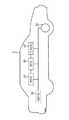
도 2는 하나의 션트저항을 포함하는 버스바를 이용한 전류 측정 장치를 개략적으로 도시한 도면이다.
도 3은 본 발명의 일 실시예(1)에 따른 션트저항을 이용한 전류 측정 장치를 개략적으로 도시한 도면이다.
도 4는 본 발명의 일 실시예(2)에 따른 션트저항을 이용한 전류 측정 장치를 개략적으로 도시한 도면이다.1 is a schematic view of an electric vehicle to which a current measuring apparatus using a shunt resistor according to an embodiment of the present invention can be applied.
2 is a schematic view of a current measuring apparatus using a bus bar including one shunt resistor.
3 is a view schematically showing a current measuring apparatus using a shunt resistor according to an embodiment (1) of the present invention.
4 is a view schematically showing a current measuring apparatus using a shunt resistor according to an embodiment (2) of the present invention.
본 발명을 첨부된 도면을 참조하여 상세히 설명하면 다음과 같다. 여기서, 반복되는 설명, 본 발명의 요지를 불필요하게 흐릴 수 있는 공지 기능, 및 구성에 대한 상세한 설명은 생략한다. 본 발명의 실시형태는 당 업계에서 평균적인 지식을 가진 자에게 본 발명을 보다 완전하게 설명하기 위해서 제공되는 것이다. 따라서, 도면에서의 요소들의 형상 및 크기 등은 보다 명확한 설명을 위해 과장될 수 있다.The present invention will now be described in detail with reference to the accompanying drawings. Hereinafter, a repeated description, a known function that may obscure the gist of the present invention, and a detailed description of the configuration will be omitted. Embodiments of the present invention are provided to more fully describe the present invention to those skilled in the art. Accordingly, the shapes and sizes of the elements in the drawings and the like can be exaggerated for clarity.
명세서 전체에서, 어떤 부분이 어떤 구성 요소를 "포함"한다고 할 때, 이는 특별히 반대되는 기재가 없는 한 다른 구성 요소를 제외하는 것이 아니라 다른 구성 요소를 더 포함할 수 있는 것을 의미한다.Throughout the specification, when an element is referred to as "comprising ", it means that it can include other elements as well, without excluding other elements unless specifically stated otherwise.
또한, 명세서에 기재된 "...부"의 용어는 하나 이상의 기능이나 동작을 처리하는 단위를 의미하며, 이는 하드웨어나 소프트웨어 또는 하드웨어 및 소프트웨어의 결합으로 구현될 수 있다.Further, the term "part" in the description means a unit for processing one or more functions or operations, which may be implemented by hardware, software, or a combination of hardware and software.
도 1은 본 발명의 일 실시예에 따른 션트(Shunt)저항을 이용한 전류 측정 장치가 적용될 수 있는 전기 자동차를 개략적으로 도시한 도면이다.1 is a schematic view of an electric vehicle to which a current measuring device using a shunt resistor according to an embodiment of the present invention can be applied.
도 1에서 본 발명의 일 실시예에 따른 션트저항을 이용한 전류 측정 장치가 전기 자동차(1)에 적용된 예를 도시하고 있으나, 본 발명의 일 실시예에 따른 션트저항를 이용한 전류 측정 장치는 전기 자동차 이외에도 가정용 또는 산업용 에너지 저장 시스템(Energy Storage System; ESS)이나 무정전 전원 공급 장치(Uninterruptible Power Supply; UPS) 시스템 등 이차 전지가 적용될 수 있는 분야라면 어떠한 기술 분야라도 적용될 수 있다.1, an electric current measuring apparatus using a shunt resistor according to an embodiment of the present invention is applied to an
전기 자동차(1)는 배터리(10), BMS(Battery Management System, 20), ECU(Electronic Control Unit, 30), 인버터(40) 및 모터(50)를 포함하여 구성될 수 있다The
배터리(10)는 모터(50)에 구동력을 제공하여 전기 자동차(1)를 구동시키는 전기 에너지원이다. 배터리(10)는 모터(50) 및/또는 내연 기관(미도시)의 구동에 따라 인버터(40)에 의해 충전되거나 방전될 수 있다.The
여기서, 배터리(10)의 종류는 특별히 한정되지 않으며, 예컨대 배터리(10)는 리튬 이온 전지, 리튬 폴리머 전지, 니켈 카드뮴 전지, 니켈 수소 전지, 니켈 아연 전지 등으로 구성될 수 있다.Here, the type of the
또한, 배터리(10)는 복수의 전지 셀이 직렬 및/또는 병렬로 연결되어 있는 전지 팩으로 형성된다. 그리고, 배터리(10)는 하나 이상의 전지 팩을 포함할 수 있다.The
BMS(20)는 배터리(10)의 상태를 추정하고, 추정한 상태 정보를 이용하여 배터리(10)를 관리한다. 예컨대, BMS(20)는 배터리(10)의 잔존 용량(State Of Charging; SOC), 잔존 수명(State Of Health; SOH), 최대 입출력 전력 허용량, 출력 전압 등 배터리(10) 상태 정보를 추정하고 관리한다. 그리고, BMS(20)는 이러한 상태 정보를 이용하여 배터리(10)의 충전 또는 방전을 제어하며, 나아가 배터리(10)의 교체 시기 추정도 가능하다.The BMS 20 estimates the state of the
BMS(20)는 후술하는 본 발명의 일 실시예에 따른 션트저항을 이용한 전류 측정 장치(도 3의 100(a) 및 도 4의 100(b))를 포함하거나 션트저항을 이용한 전류 측정 장치에 연결되어 동작할 수 있다. BMS(20)는 션트저항을 이용한 전류 측정 장치(100(a) 및 100(b))에 포함된 션트저항을 이용하여 배터리의 충방전 전류 값을 측정할 수 있으며, 이를 바탕으로 배터리(10)의 저전압 및 과전압 상태와 같은 동작 이상 상태를 판단할 수 있다.The
ECU(30)는 전기 자동차(1)의 상태를 제어하는 전자적 제어 장치이다. 예컨대, ECU(30)는 액셀러레이터(accelerator), 브레이크(break), 속도 등의 정보에 기초하여 토크 정도를 결정하고, 모터(50)의 출력이 토크 정보에 맞도록 제어한다.The ECU 30 is an electronic control device for controlling the state of the
또한, ECU(30)는 BMS(20)에 의해 배터리(10)가 충전 또는 방전될 수 있도록 인버터(40)에 제어 신호를 보낸다.The
인버터(40)는 ECU(30)의 제어 신호에 기초하여 배터리(10)가 충전 또는 방전되도록 한다.The
모터(50)는 배터리(10)의 전기 에너지를 이용하여 ECU(30)로부터 전달되는 제어 정보(예컨대, 토크 정보)에 기초하여 전기 자동차(1)를 구동한다.The
이하 도2 내지 도 4를 참조하여, 본 발명의 일 실시예에 따른 션트저항을 이용한 전류 측정 장치에 대해서 설명하도록 한다.Hereinafter, a current measuring apparatus using a shunt resistor according to an embodiment of the present invention will be described with reference to FIGS. 2 to 4. FIG.
도 2는 하나의 션트저항을 포함하는 버스바를 이용한 전류 측정 장치를 개략적으로 도시한 도면이다.2 is a schematic view of a current measuring apparatus using a bus bar including one shunt resistor.
도 2를 참조하면, 전류 측정 소자는 배터리 모듈의 전류를 측정하기 위해 션트저항(120)에 전류가 흐를 때 션트저항(120) 양단에 인가되는 전압값에 기반하여 측정부(130)에서 배터리(10) 모듈의 전류값을 산출한다.Referring to FIG. 2, the current measuring device measures the current of the
이와 같이, 하나의 션트저항(120) 및 하나의 측정부(130)를 통해 배터리 모듈의 전류값을 산출할 경우, 신뢰도가 높지 않기 때문에 고신뢰성 션트저항(120) 및 측정부(130)을 이용하거나 복수 개의 션트저항(120) 및 복수 개의 측정부(130를 통해 배터리(10) 모듈의 전류를 산출해야 한다. 그러나 전류 측정 장치는 고신뢰성 션트저항(120) 및 측정부(130)는 가격적인 문제점이 있으며, 복수 개의 션트저항(120) 및 측정부(130)를 사용하는 경우, 배터리(10) 모듈의 부피가 증가하기 때문에 배터리(10) 모듈의 고 효율화 및 고 에너지밀도화에 악영향을 끼친다.When the current value of the battery module is calculated through one
도 3은 본 발명의 일 실시예(1)에 따른 션트저항을 이용한 전류 측정 장치를 개략적으로 도시한 도면이다.3 is a view schematically showing a current measuring apparatus using a shunt resistor according to an embodiment (1) of the present invention.
도 3을 참조하면, 션트저항을 이용한 전류 측정 장치(100(a))는 버스바(110), 션트저항(120) 및 측정부(130)를 포함하여 구성될 수 있다.3, a current measuring apparatus 100 (a) using a shunt resistor may include a
도 3에 도시된 션트저항을 이용한 전류 측정 장치(100(a))는 일 실시예에 따른 것이고, 그 구성요소들이 도 4에 도시된 실시예에 한정되는 것은 아니며, 필요에 따라 부가, 변경 또는 삭제 될 수 있다.The current measuring apparatus 100 (a) using the shunt resistor shown in FIG. 3 is according to one embodiment, and the components thereof are not limited to the embodiment shown in FIG. 4, Can be deleted.
버스바(110)는 배터리(10) 팩 내에 포함된 두 개의 배터리(10) 모듈의 모듈 단자를 서로 연결할 수 있다. 그러나 본 발명은 이에 제한하지 않고, 버스바(110)는 적용하고자 하는 션트저항을 이용한 전류 측정 장치(100(a))의 개수에 따라 두 개 이상의 배터리(10) 모듈의 모듈 단자를 서로 연결할 수 있다. 버스바(110)의 형태 또한 연결하고자 하는 배터리(10) 모듈의 형태 및 배치에 따라 다양하게 형성될 수 있다. 일 예로, 사용자가 세 개 이상의 배터리(10) 모듈의 모듈 단자를 연결하기 위해 션트저항을 이용한 전류 측정 장치(100(a))가 적용된 버스바를 이용하고자 하는 경우, 세 개 이상의 배터리(10) 모듈을 연결하기 위한 세 개 이상의 버스바를 일체화한 하나의 버스바(110)를 이용하여 세 개 이상의 배터리(10) 모듈의 모듈 단자를 연결할 수 있다.The
또한 버스바(110)는 후술되는 션트저항(120)을 두 개 이상 포함할 수 있다.The
션트저항(120)은 배터리(10) 모듈의 전압을 측정하기 위해 사용될 수 있으며, 버스바(110) 상에 둘 이상의 션트저항(120)이 위치하여 버스바(110)를 적어도 두 개 이상의 영역으로 분리시킬 수 있다.The
추가적으로 션트저항을 이용한 전류 측정 장치(100(a))는 단자 션트저항(미도시)를 더 포함할 수 있다.In addition, the current measuring apparatus 100 (a) using the shunt resistor may further include a terminal shunt resistor (not shown).
단자 션트저항(미도시)는 적어도 일부 영역에 관통홀을 포함할 수 있으며, 배터리(10) 모듈의 모듈 단자에 추가적으로 설치함으로써, 전류 측정의 신뢰성을 높일 수 있다. 여기서 관통홀은 배터리(10) 모듈의 모듈 단자를 삽입시킬 수 있도록 배터리(10) 모듈 단자의 직경 크기 이상으로 형성될 수 있다.The terminal shunt resistor (not shown) may include a through hole in at least a part of the area, and additionally to the module terminal of the
또한, 단자 션트저항은 제1 접속단자(미도시) 및 제2 접속단자(미도시)를 포함할 수 있다.In addition, the terminal shunt resistor may include a first connection terminal (not shown) and a second connection terminal (not shown).
제1 접속단자 및 제2 접속단자는 단자 션트저항의 양단에 인가되는 전압값을 측정하기 위해 설치될 수 있다.The first connection terminal and the second connection terminal may be provided to measure a voltage value applied across the terminal shunt resistor.
이를 위해 제1 접속단자 및 제2 접속단자의 일부 영역에 관통홀이 포함될 수 있으며, 제1 접속단자 및 제2 접속단자 사이에 단자 션트저항을 두고 배터리(10) 모듈의 모듈 단자에 삽입해 설치할 수 있다. 일 예로, 단자 션트저항, 제1 접속단자 및 제2 접속단자는 와셔 형태로 형성될 수 있으며, 배터리(10) 모듈의 모듈 단자는 볼트 형태로 형성될 수 있다. 와셔 형태로 형성된 단자 션트저항, 제1 접속단자 및 제2접속단자는 내부에 형성된 관통홀을 볼트 형태의 모듈 단자에 나사 결합하여 전기적으로 연결될 수 있다.For this, a through hole may be included in a part of the first connection terminal and the second connection terminal, and a terminal shunt resistor may be provided between the first connection terminal and the second connection terminal to be inserted into the module terminal of the battery module . For example, the terminal shunt resistor, the first connection terminal, and the second connection terminal may be formed in a washer shape, and the module terminal of the
또한, 제1 접속단자, 단자 션트저항 및 제2 접속단자는 결합된 형태로 제작될 수 있다. 일 예로, 제1 접속단자, 제2 제 접속단자 및 단자 션트저항이 하나의 와셔 형태로 제작될 수 있다.Also, the first connection terminal, the terminal shunt resistor, and the second connection terminal may be manufactured in a combined form. For example, the first connection terminal, the second connection terminal, and the terminal shunt resistor may be fabricated in the form of a single washer.
측정부(130)는 둘 이상의 션트저항(120)에 인가되는 전압값을 각각 측정하고, 측정된 전압값에 기반하여 전류값을 각각 산출할 수 있다.The measuring
이를 위해 하나 이상의 측정부(130)를 포함할 수 있다. 또한 측정부(130)는 전압 증폭부(131) 및 전류 산출부(132)를 포함할 수 있다.For this, one or
전압 증폭부(131)는 션트저항(120)에 인가되는 배터리(10) 모듈의 전압값을 증폭시키는 역할을 수행할 수 있다. 일반적으로 션트저항의 저항값은 부하에 미치는 영향을 최소화하기 위해 매우 작은 값의 저항을 사용한다. 일 예로 션트저항(120)의 저항값은 100u옴 일 수 있다. 따라서 션트저항(120)에 인가되는 배터리(10) 모듈의 전압값은 매우 작기 때문에, 이를 증폭시켜줄 필요성이 있다.The
따라서 전압 증폭부(131)은 션트저항에 인가되는 작은 전압값을 증폭할 수 있다. 일 예로, 전압 증폭부(131)는 하나 이상의 연산 증폭기(Operating Amplifier)가 직렬 및 병렬로 연결된 회로일 수 있으며, 연산 증폭기에 기설정된 게인(Gain)값에 기반하여 션트저항(120) 양단에 인가되는 전압값을 증폭시킬 수 있다.Therefore, the
전류 산출부(132)는 전압 증폭부(131)를 통해 증폭된 션트저항(120) 양단에 인가되는 전압값에 기반하여 배터리(10) 모듈의 전류를 산출할 수 있다. 예를 들면, 100uΩ의 션트 저항(170)에 의 전류가 흐르면 옴의 법칙(V = I*R)에 의해 1mV의 전위차가 발생하며, 발생한 전위차는 증폭부(131)에 기 설정된 게인(gain)값을 곱한 만큼 증폭되어 출력된다. 반대로 출력 전압이 4.5V인 경우 기 설정된 게인(gain)값으로 나눠주면 0.045V라는 전위차가 발생하였음을 알 수 있고, 옴의 법칙(V = I*R)에 의해 450A가 흐른다는 것을 알 수 있다.The
복수 개의 션트저항(120)을 각각 측정하기 위해 전류 측정 장치는 하나 이상의 측정부(130)를 구비할 수 있으며, 하나 이상의 측정부(130)는 하나의 측정 모듈(150)를 구성할 수 있다.In order to measure each of the plurality of
측정 모듈(150)은 하나 이상의 측정부(130)로 구성되며, 하나 이상의 측정부(130)의 동작을 제어할 수 있는 제어부(미도시)를 포함할 수 있다.The
제어부는 하나 이상의 측정부의 동작을 온 또는 오프 제어할 수 있다. 제어부는 이상이 있는 측정부의 동작을 오프시킬 수 있다. 또한, 고 신뢰성이 요구되지 않을 경우 제어부는 복수 개의 측정부 중 일부 측정부만 선택적으로 동작시켜 사용할 수 있다. 일 예로 하나 이상의 측정부(130)는 각각 스위치(미도시)와 연결될 수 있으며, 제어부는 측정부(130)와 연결된 스위치의 온 또는 오프를 제어함으로써 측정부(130)의 동작을 제어할 수 있다.The control unit may control on or off the operation of the at least one measuring unit. The control unit can turn off the operation of the abnormal measurement unit. In addition, when high reliability is not required, the control unit can selectively use only some measurement units among a plurality of measurement units. For example, one or
도 4는 본 발명의 일 실시예(2)에 따른 션트저항을 이용한 전류 측정 장치를 개략적으로 도시한 도면이다.4 is a view schematically showing a current measuring apparatus using a shunt resistor according to an embodiment (2) of the present invention.
도 4를 참조하면, 션트저항을 이용한 전류 측정 장치(100(b))는 션트저항을 이용한 전류 측정 장치(100(a))와 마찬가지로 버스바(110'), 션트저항(120') 및 측정부(130')를 포함하여 구성될 수 있다.Referring to FIG. 4, the current measuring device 100 (b) using the shunt resistor is similar to the current measuring device 100 (a) using the shunt resistor, and the bus bar 110 ', the shunt resistor 120' And a part 130 '.
버스바(110')는 실시예(1)에서의 버스바(110)와 동일하게 배터리(10) 팩 내에 포함된 두 개의 배터리(10) 모듈의 모듈 단자를 서로 연결할 수 있다. 버스바(110')는 적용하고자 하는 션트저항을 이용한 전류 측정 장치(100(b))의 개수에 따라 두 개 이상의 배터리(10) 모듈의 모듈 단자를 서로 연결할 수 있다. 버스바(110)의 형태 또한 연결하고자 하는 배터리(10) 모듈의 형태 및 배치에 따라 다양하게 형성될 수 있다.The bus bar 110 'can connect the module terminals of the two
션트저항(120')은 배터리(10) 모듈의 전압을 측정하기 위해 사용될 수 있다. 또한, 션트저항(120')은 버스바(110')상에 위치하여 버스바(110')를 두 개의 영역으로 분리시킬 수 있다. 그러나 본 발명은 이에 제한하지 않고, 사용자의 요구 및 사용 환경에 따라 하나 이상의 션트저항(120')은 버스바(110')상에 위치될 수 있으며, 버스바(120')를 적어도 두 개 이상의 영역으로 분리시킬 수 있다.The shunt resistor 120 'may be used to measure the voltage of the
션트저항(120)은 배터리(10) 모듈의 전압을 측정하기 위해 사용될 수 있으며, 버스바(110) 상에 둘 이상의 션트저항(120)이 위치하여 버스바(110)를 적어도 두 개 이상의 영역으로 분리시킬 수 있다.The
추가적으로 션트저항을 이용한 전류 측정 장치(100(b))는 단자 션트저항(미도시)를 더 포함할 수 있다.In addition, the current measuring apparatus 100 (b) using the shunt resistor may further include a terminal shunt resistor (not shown).
단자 션트저항(미도시)는 적어도 일부 영역에 모듈단자 직경 크기의 관통홀을 포함할 수 있으며, 배터리(10) 모듈의 모듈 단자에 추가적으로 설치함으로써, 전류 측정의 신뢰성을 높일 수 있다. 이를 위해 단자 션트저항은 제1 접속단자(미도시) 및 제2 접속단자(미도시)를 포함할 수 있다.The terminal shunt resistor (not shown) may include a through hole having a size of a module terminal diameter in at least a part of the area, and additionally provided at a module terminal of the
제1 접속단자 및 제2 접속단자는 단자 션트저항의 양단에 인가되는 전압값을 측정하기 위해 설치될 수 있다.The first connection terminal and the second connection terminal may be provided to measure a voltage value applied across the terminal shunt resistor.
이를 위해 제1 접속단자 및 제2 접속단자의 일부 영역에 관통홀이 포함될 수 있으며, 제1 접속단자 및 제2 접속단자 사이에 단자 션트저항을 두고 배터리(10) 모듈의 모듈 단자에 삽입해 설치할 수 있다. 일 예로, 실시예(1)와 같이 단자 션트저항, 제1 접속단자 및 제2 접속단자는 와셔 형태로 형성될 수 있다. 또한, 제1 접속단자, 단자 션트저항 및 제2 접속단자는 결합된 형태로 제작될 수 있다.For this, a through hole may be included in a part of the first connection terminal and the second connection terminal, and a terminal shunt resistor may be provided between the first connection terminal and the second connection terminal to be inserted into the module terminal of the battery module . For example, the terminal shunt resistor, the first connection terminal, and the second connection terminal may be formed in a washer shape as in the embodiment (1). Also, the first connection terminal, the terminal shunt resistor, and the second connection terminal may be manufactured in a combined form.
또한 션트저항(120')은 후술되는 노드부(140)를 포함할 수 있다.The shunt resistor 120 'may include a
노드부(140)은 션트저항(120')의 전압값을 측정하기 위한 접점으로, 션트저항 내에 적어도 세 개 이상의 노드(141,142,143)를 포함할 수 있다.The
노드(141,142,143)의 위치 및 개수는 션트저항(120')의 종류, 크기, 측정부(130')의 개수 및 사용자의 요구에 따라 형성될 수 있다.The positions and the number of the
측정부(130')는 하나 이상으로 구성되며, 션트저항(120')에 포함된 세 개 이상의 노드(141,142,143) 중 적어도 두 개의 노드를 선택할 수 있다. 측정부(130')는 선택한 노드 사이에 인가되는 전압값을 기반으로, 배터리 모듈의 전류값을 측정할 수 있다.The measurement unit 130 'may include at least one node, and may select at least two of the three or
또한 측정부(130')는 실시예(1)에서의 측정부(130)과 마찬가지로 전압 증폭부(131') 및 전류 산출부(132')를 포함할 수 있다.The measuring unit 130 'may include a voltage amplifying unit 131' and a current calculating unit 132 'in the same manner as the measuring
여기서 전압 증폭부(131') 및 전류 산출부(132')의 역할 및 원리는 실시예(1)에서의 전압 증폭부(131) 및 전류 산출부(132)와 동일하게 적용될 수 있다.Here, the role and principle of the voltage amplifying unit 131 'and the current calculating unit 132' can be applied in the same manner as the
측정부(130')는 션트저항(120')에 포함된 노드(141,142,143) 사이의 전압값을 각각 측정하기 위해 하나 이상으로 구성될 수 있다. 하나 이상의 측정부(130')는 하나의 측정 모듈(150')을 구성할 수 있다.The measurement unit 130 'may be configured to measure voltage values between the
측정 모듈(150')은 하나 이상의 측정부(130')를 포함하며, 하나 이상의 측정부(130')의 동작을 제어할 수 있는 제어부(미도시)를 포함할 수 있다.The measurement module 150 'may include at least one measurement unit 130' and a control unit (not shown) that can control the operation of the at least one measurement unit 130 '.
제어부는 하나 이상의 측정부의 동작을 온 또는 오프 제어할 수 있으며, 이를 통해 이상이 있는 측정부의 동작을 오프시킬 수 있다. 또한, 제어부는 고 신뢰성이 요구되지 않을 경우 복수 개의 측정부 중 일부 측정부만 선택적으로 동작시킬 수 있다. 추가적으로 제어부는 션트저항(120')내에 포함된 세 개 이상의 노드(141,142,143)중 적어도 두 개 이상의 노드를 선택할 수 있다. 일 예로, 각 노드(141,142,143)는 노드(141)와 노드(142), 노드(141)와 노드(143) 및 노드(142)와 노드(143)등 다양한 조합을 가질 수 있으며, 각각의 조합마다 스위치(미도시)가 연결될 수 있다. 제어부는 조합된 노드(141,142,143) 사이에 연결된 스위치를 제어함으로써, 적어도 두 개 이상으로 구성된 조합을 선택할 수 있다.The control unit can control the operation of one or more measurement units on or off, thereby turning off the operation of the measurement unit having an abnormality. In addition, when high reliability is not required, the control unit can selectively operate only some of the plurality of measurement units. In addition, the control unit may select at least two or more of the three or
이상 본 발명의 특정 실시예를 도시하고 설명하였으나, 본 발명의 기술사상은 첨부된 도면과 상기한 설명내용에 한정하지 않으며 본 발명의 사상을 벗어나지 않는 범위 내에서 다양한 형태의 변형이 가능함은 이 분야의 통상의 지식을 가진 자에게는 자명한 사실이며, 이러한 형태의 변형은, 본 발명의 정신에 위배되지 않는 범위 내에서 본 발명의 특허청구범위에 속한다고 볼 것이다.While the present invention has been particularly shown and described with reference to exemplary embodiments thereof, it is clearly understood that the same is by way of illustration and example only and is not to be taken as limitations. It will be understood by those skilled in the art that various changes in form and details may be made therein without departing from the spirit and scope of the invention as defined by the appended claims.
10: 배터리
110: 버스바
120: 션트저항
130: 측정부
131: 전압 증폭부
132: 전류 산출부
140: 노드부
150: 측정모듈10: Battery
110: bus bar
120: Shunt resistance
130:
131:
132: current calculating section
140:
150: Measurement module
Claims (10)
Translated fromKorean상기 버스바 상에 위치하며, 상기 버스바를 적어도 두 개 이상의 영역으로 분리시키는 적어도 둘 이상의 션트저항; 및
상기 둘 이상의 션트저항에 인가되는 전압값을 각각 측정하고, 상기 측정된 전압값에 기반하여 전류값을 각각 산출하는 하나 이상의 측정부;를 포함하되,
상기 하나 이상의 측정부는,
하나의 측정 모듈로 구성되고,
상기 측정 모듈은,
상기 하나 이상의 측정부 각각과 연결되는 스위치 각각의 개폐 동작 제어를 통해 상기 하나 이상의 측정부 각각의 동작을 제어할 수 있는 제어부;를 포함하는 것을 특징으로 하는,
션트저항을 이용한 전류 측정 장치.
One or more bus bars connecting the module terminals of the two battery modules included in the battery pack to each other;
At least two or more shunt resistors located on the bus bar and separating the bus bar into at least two regions; And
And at least one measuring unit for measuring a voltage value applied to the at least two shunt resistors and calculating a current value based on the measured voltage value,
Wherein the at least one measuring unit comprises:
A measurement module,
The measurement module comprising:
And a controller capable of controlling the operation of each of the at least one measuring unit through an opening / closing operation control of each switch connected to each of the at least one measuring unit.
Current measuring device using shunt resistor.
상기 측정부는,
상기 션트저항에 인가되는 전압값을 증폭하는 전압 증폭부; 및
상기 증폭된 전압값에 기반하여 상기 배터리 모듈의 전류값을 산출하는 전류 산출부;를 포함하는 것을 특징으로 하는,
션트저항을 이용한 전류 측정 장치.
The method according to claim 1,
Wherein the measuring unit comprises:
A voltage amplifying unit for amplifying a voltage value applied to the shunt resistor; And
And a current calculator calculating a current value of the battery module based on the amplified voltage value.
Current measuring device using shunt resistor.
적어도 일부 영역에 관통홀을 가지는 단자 션트저항; 및
상기 단자 션트저항 양단에 인가되는 전압값을 측정하기 위한 제1 접속 단자 및 제2 접속 단자;를 더 포함하며,
상기 단자 션트저항을 상기 제 1 및 제2 접속 단자로 사이에 두어 상기 모듈 단자를 상기 관통홀에 삽입해 설치한 것을 특징으로 하는,
션트저항을 이용한 전류 측정 장치.
The method according to claim 1,
A terminal shunt resistor having a through hole in at least a part of the region; And
And a first connection terminal and a second connection terminal for measuring a voltage value applied across the terminal shunt resistor,
And the module terminal is inserted into the through hole with the terminal shunt resistor being interposed between the first and second connection terminals.
Current measuring device using shunt resistor.
상기 단자 션트저항은 와셔 형태, 상기 모듈 단자는 볼트 형태이며,
상기 와셔 형태 션트저항 내부에 형성된 관통홀을 볼트 형태 모듈 단자에 나사 결합하여 상기 단자 션트저항과 상기 모듈 단자를 전기적으로 연결하는 것을 특징으로 하는,
션트저항을 이용한 전류 측정 장치.
5. The method of claim 4,
The terminal shunt resistor has a washer shape, the module terminal has a bolt shape,
And a through hole formed in the washer-type shunt resistor is screwed to the bolt-type module terminal to electrically connect the terminal shunt resistor and the module terminal.
Current measuring device using shunt resistor.
상기 버스바 상에 위치하며, 상기 버스바를 두 개의 영역으로 분리시키는 션트저항; 및
상기 션트저항에 포함된 세 개 이상의 노드 중 적어도 두 개의 노드를 선택하여 상기 선택된 두 개의 노드 사이에 인가되는 전압값을 기반으로, 상기 배터리 모듈의 전류값을 측정하는 하나 이상의 측정부;를 포함하되,
상기 하나 이상의 측정부는,
하나의 측정 모듈로 구성되며,
상기 측정 모듈은,
상기 세 개 이상의 노드와 상기 하나 이상의 측정부의 사이 경로에 연결되는 스위치의 개폐 동작 제어를 통해, 상기 션트저항의 전압값을 측정하기 위한 노드를 선택하는 제어부;를 포함하는 것을 특징으로 하는,
션트저항을 이용한 전류 측정 장치.
One or more bus bars connecting the module terminals of the two battery modules included in the battery pack to each other;
A shunt resistor located on the bus bar and separating the bus bar into two regions; And
And at least one measuring unit for selecting at least two nodes among three or more nodes included in the shunt resistor and measuring a current value of the battery module based on a voltage value applied between the selected two nodes, ,
Wherein the at least one measuring unit comprises:
It consists of one measurement module,
The measurement module comprising:
And a controller for selecting a node for measuring a voltage value of the shunt resistor through an opening / closing operation control of a switch connected to a path between the three or more nodes and the at least one measuring unit.
Current measuring device using shunt resistor.
상기 측정부는,
상기 션트저항에 인가되는 전압값을 증폭하는 전압 증폭부; 및
상기 증폭된 전압값에 기반하여 상기 배터리 모듈의 전류값을 산출하는 전류 산출부;를 포함하는 것을 특징으로 하는,
션트저항을 이용한 전류 측정 장치.
The method according to claim 6,
Wherein the measuring unit comprises:
A voltage amplifying unit for amplifying a voltage value applied to the shunt resistor; And
And a current calculator calculating a current value of the battery module based on the amplified voltage value.
Current measuring device using shunt resistor.
적어도 일부 영역에 관통홀을 가지는 단자 션트저항; 및
상기 단자 션트저항 양단에 인가되는 전압값을 측정하기 위한 제1 접속 단자 및 제2 접속 단자;를 더 포함하며,
상기 단자 션트저항을 상기 제 1 및 제2 접속 단자로 사이에 두어 상기 모듈 단자를 상기 관통홀에 삽입해 설치한 것을 특징으로 하는,
션트저항을 이용한 전류 측정 장치.
The method according to claim 6,
A terminal shunt resistor having a through hole in at least a part of the region; And
And a first connection terminal and a second connection terminal for measuring a voltage value applied across the terminal shunt resistor,
And the module terminal is inserted into the through hole with the terminal shunt resistor being interposed between the first and second connection terminals.
Current measuring device using shunt resistor.
상기 단자 션트저항은 와셔 형태, 상기 모듈 단자는 볼트 형태이며,
상기 와셔 형태 션트저항 내부에 형성된 관통홀을 볼트 형태 모듈 단자에 나사 결합하여 상기 단자 션트저항과 상기 모듈 단자를 전기적으로 연결하는 것을 특징으로 하는,
션트저항을 이용한 전류 측정 장치.
10. The method of claim 9,
The terminal shunt resistor has a washer shape, the module terminal has a bolt shape,
And a through hole formed in the washer-type shunt resistor is screwed to the bolt-type module terminal to electrically connect the terminal shunt resistor and the module terminal.
Current measuring device using shunt resistor.
Priority Applications (7)
| Application Number | Priority Date | Filing Date | Title |
|---|---|---|---|
| KR1020160097245AKR101998091B1 (en) | 2016-07-29 | 2016-07-29 | Apparatus for measuring current using shunt resistor |
| CN201780004998.4ACN108431619B (en) | 2016-07-29 | 2017-05-02 | Current Measurement Devices Using Shunt Resistors |
| EP17834606.0AEP3379279B1 (en) | 2016-07-29 | 2017-05-02 | Current measurement apparatus using shunt resistor |
| PCT/KR2017/004690WO2018021661A1 (en) | 2016-07-29 | 2017-05-02 | Current measurement apparatus using shunt resistor |
| US16/060,287US10802049B2 (en) | 2016-07-29 | 2017-05-02 | Current measurement apparatus using shunt resistor |
| PL17834606TPL3379279T3 (en) | 2016-07-29 | 2017-05-02 | Current measurement apparatus using shunt resistor |
| JP2018528707AJP6872549B2 (en) | 2016-07-29 | 2017-05-02 | Current measuring device using shunt resistor |
Applications Claiming Priority (1)
| Application Number | Priority Date | Filing Date | Title |
|---|---|---|---|
| KR1020160097245AKR101998091B1 (en) | 2016-07-29 | 2016-07-29 | Apparatus for measuring current using shunt resistor |
Publications (2)
| Publication Number | Publication Date |
|---|---|
| KR20180013466A KR20180013466A (en) | 2018-02-07 |
| KR101998091B1true KR101998091B1 (en) | 2019-07-09 |
Family
ID=61017132
Family Applications (1)
| Application Number | Title | Priority Date | Filing Date |
|---|---|---|---|
| KR1020160097245AActiveKR101998091B1 (en) | 2016-07-29 | 2016-07-29 | Apparatus for measuring current using shunt resistor |
Country Status (7)
| Country | Link |
|---|---|
| US (1) | US10802049B2 (en) |
| EP (1) | EP3379279B1 (en) |
| JP (1) | JP6872549B2 (en) |
| KR (1) | KR101998091B1 (en) |
| CN (1) | CN108431619B (en) |
| PL (1) | PL3379279T3 (en) |
| WO (1) | WO2018021661A1 (en) |
Cited By (2)
| Publication number | Priority date | Publication date | Assignee | Title |
|---|---|---|---|---|
| KR102532430B1 (en) | 2022-11-21 | 2023-05-15 | 스마트전자 주식회사 | Busbar assembly and current measuring device |
| KR102555653B1 (en) | 2022-11-10 | 2023-07-17 | 스마트전자 주식회사 | Battery monitoring method and device |
Families Citing this family (15)
| Publication number | Priority date | Publication date | Assignee | Title |
|---|---|---|---|---|
| KR102312445B1 (en)* | 2018-03-28 | 2021-10-12 | 주식회사 엘지에너지솔루션 | Shunt resistor and apparatus for detecting current including the same |
| KR102247090B1 (en) | 2018-08-10 | 2021-04-29 | 주식회사 엘지화학 | Current detecting circuit, battery management system and battery pack |
| JP7207074B2 (en)* | 2019-03-27 | 2023-01-18 | 株式会社Gsユアサ | BATTERY MANAGEMENT DEVICE, POWER STORAGE DEVICE, BATTERY MANAGEMENT METHOD, AND COMPUTER PROGRAM |
| KR102779845B1 (en)* | 2019-12-03 | 2025-03-12 | 엘지이노텍 주식회사 | Apparatus for detecting current of 3-Phase inverter and method thereof |
| DE102020101070B4 (en)* | 2020-01-17 | 2025-01-30 | Wieland & Munich Electrification Gmbh | Measuring circuit with a resistance arrangement and method for producing a band-shaped material composite for the resistance arrangement |
| US12174269B2 (en) | 2020-03-20 | 2024-12-24 | InductEV, Inc. | Current sensing in a wireless power transfer system |
| US11585836B2 (en) | 2020-03-20 | 2023-02-21 | InductEV, Inc. | Current sensing in a wireless power transfer system |
| US11784503B2 (en) | 2021-02-22 | 2023-10-10 | Inductev Inc. | Passive arc detection and mitigation in wireless power transfer system |
| US11579202B2 (en)* | 2020-06-09 | 2023-02-14 | Samsung Sdi Co., Ltd. | Electric current measuring arrangement and battery system |
| JP2022030815A (en)* | 2020-08-07 | 2022-02-18 | 株式会社デンソー | Current detector |
| JP7581819B2 (en)* | 2020-12-09 | 2024-11-13 | 株式会社Soken | Current Detector |
| DE102021102217A1 (en) | 2021-02-01 | 2022-08-04 | HELLA GmbH & Co. KGaA | Method and device for determining an electric current and battery |
| DE102021205279A1 (en) | 2021-05-25 | 2022-12-01 | Robert Bosch Gesellschaft mit beschränkter Haftung | Current measuring resistor for measuring an electric current |
| JP2024533626A (en)* | 2021-09-20 | 2024-09-12 | グーグル エルエルシー | Apparatus with integrated current sensor - Patent application |
| CN221765567U (en)* | 2023-09-08 | 2024-09-24 | 宁德时代新能源科技股份有限公司 | Current divider module, current collection system, circuit and vehicle |
Citations (3)
| Publication number | Priority date | Publication date | Assignee | Title |
|---|---|---|---|---|
| JP2008047571A (en)* | 2006-08-10 | 2008-02-28 | Matsushita Electric Ind Co Ltd | Shunt resistor and current measuring device using shunt resistor |
| JP2009204531A (en)* | 2008-02-28 | 2009-09-10 | Sanyo Electric Co Ltd | Shunt resistor, and power supply device for vehicle equipped with the shunt resistor |
| JP2011053095A (en)* | 2009-09-02 | 2011-03-17 | Furukawa Electric Co Ltd:The | Current monitoring device |
Family Cites Families (10)
| Publication number | Priority date | Publication date | Assignee | Title |
|---|---|---|---|---|
| US6304062B1 (en)* | 1999-10-28 | 2001-10-16 | Powersmart, Inc. | Shunt resistance device for monitoring battery state of charge |
| US7319304B2 (en) | 2003-07-25 | 2008-01-15 | Midtronics, Inc. | Shunt connection to a PCB of an energy management system employed in an automotive vehicle |
| JP4897964B2 (en)* | 2007-09-10 | 2012-03-14 | 古河電気工業株式会社 | Current detector |
| US8970246B2 (en)* | 2010-12-23 | 2015-03-03 | Caterpillar Inc. | Assembly and circuit structure for measuring current through an integrated circuit module device |
| EP2756318A2 (en)* | 2011-09-12 | 2014-07-23 | Metroic Limited | Current measurement |
| KR101473397B1 (en)* | 2012-06-07 | 2014-12-16 | 주식회사 엘지화학 | Apparatus and method for checking current sensor abnormality in battery pack |
| GB2508836A (en) | 2012-12-12 | 2014-06-18 | Sony Corp | Shunt resistor current sense circuit for use in a battery state of charge meter |
| US9523720B2 (en)* | 2013-03-15 | 2016-12-20 | Infineon Technologies Ag | Multiple current sensor device, a multiple current shunt device and a method for providing a sensor signal |
| JP2016003916A (en) | 2014-06-16 | 2016-01-12 | 株式会社オートネットワーク技術研究所 | Current detection circuit |
| US9945886B2 (en)* | 2014-09-25 | 2018-04-17 | Sanyo Electric Co., Ltd. | Electrical current detection device equipped with shunt resistor, and power supply device |
- 2016
- 2016-07-29KRKR1020160097245Apatent/KR101998091B1/enactiveActive
- 2017
- 2017-05-02WOPCT/KR2017/004690patent/WO2018021661A1/ennot_activeCeased
- 2017-05-02JPJP2018528707Apatent/JP6872549B2/enactiveActive
- 2017-05-02PLPL17834606Tpatent/PL3379279T3/enunknown
- 2017-05-02USUS16/060,287patent/US10802049B2/enactiveActive
- 2017-05-02EPEP17834606.0Apatent/EP3379279B1/enactiveActive
- 2017-05-02CNCN201780004998.4Apatent/CN108431619B/enactiveActive
Patent Citations (3)
| Publication number | Priority date | Publication date | Assignee | Title |
|---|---|---|---|---|
| JP2008047571A (en)* | 2006-08-10 | 2008-02-28 | Matsushita Electric Ind Co Ltd | Shunt resistor and current measuring device using shunt resistor |
| JP2009204531A (en)* | 2008-02-28 | 2009-09-10 | Sanyo Electric Co Ltd | Shunt resistor, and power supply device for vehicle equipped with the shunt resistor |
| JP2011053095A (en)* | 2009-09-02 | 2011-03-17 | Furukawa Electric Co Ltd:The | Current monitoring device |
Cited By (4)
| Publication number | Priority date | Publication date | Assignee | Title |
|---|---|---|---|---|
| KR102555653B1 (en) | 2022-11-10 | 2023-07-17 | 스마트전자 주식회사 | Battery monitoring method and device |
| EP4369003A1 (en) | 2022-11-10 | 2024-05-15 | Smart Electronics Inc. | Battery monitoring method and device |
| KR102532430B1 (en) | 2022-11-21 | 2023-05-15 | 스마트전자 주식회사 | Busbar assembly and current measuring device |
| EP4372390A1 (en) | 2022-11-21 | 2024-05-22 | Smart Electronics Inc. | Bus bar assembly and current measuring device |
Also Published As
| Publication number | Publication date |
|---|---|
| CN108431619B (en) | 2021-01-26 |
| JP6872549B2 (en) | 2021-05-19 |
| JP2018536166A (en) | 2018-12-06 |
| CN108431619A (en) | 2018-08-21 |
| EP3379279A1 (en) | 2018-09-26 |
| PL3379279T3 (en) | 2020-09-21 |
| US20190004094A1 (en) | 2019-01-03 |
| EP3379279A4 (en) | 2018-09-26 |
| EP3379279B1 (en) | 2020-03-11 |
| KR20180013466A (en) | 2018-02-07 |
| WO2018021661A1 (en) | 2018-02-01 |
| US10802049B2 (en) | 2020-10-13 |
Similar Documents
| Publication | Publication Date | Title |
|---|---|---|
| KR101998091B1 (en) | Apparatus for measuring current using shunt resistor | |
| US8282275B2 (en) | Device for detecting abnormality in a secondary battery | |
| US8593111B2 (en) | Assembled battery system | |
| CN102700424B (en) | Battery disconnect unit and method of assembling same | |
| CN103534897B (en) | battery control unit | |
| KR102145651B1 (en) | Battery management system | |
| KR101678277B1 (en) | Apparatus and method for detecting degradation of switch | |
| US20090295329A1 (en) | Vehicle power supply device | |
| US20150229144A1 (en) | Battery management system | |
| CN104380563B (en) | The battery management system of the robustness with the raising for negative voltage | |
| CN110832334B (en) | Fault diagnosis device | |
| KR20180037812A (en) | Apparatus and methode for fuse diagnosis using voltage distribution | |
| US10067197B2 (en) | System and method for assessing voltage threshold detecting circuitry within a battery pack | |
| KR20160103403A (en) | Battery Management System | |
| US12249696B2 (en) | Battery protection apparatus and battery system including the same | |
| KR102154379B1 (en) | Apparatus and method for measuring current using fuse | |
| KR20240025555A (en) | Bi-directional adaptive terminal voltage (BATV) of the battery pack | |
| US10744899B2 (en) | Balancing energy in a parallelized battery system | |
| JP7717115B2 (en) | Battery pack | |
| KR102818350B1 (en) | Battery module, battery management system and method | |
| JP4553853B2 (en) | Power supply for vehicle | |
| KR20180034944A (en) | System and method for balancing current consumption | |
| CN118922984A (en) | Battery pack | |
| Olson et al. | Lithium-Ion Batteries for Electric and hybrid Electric Vehicles |
Legal Events
| Date | Code | Title | Description |
|---|---|---|---|
| PA0109 | Patent application | Patent event code:PA01091R01D Comment text:Patent Application Patent event date:20160729 | |
| PG1501 | Laying open of application | ||
| A201 | Request for examination | ||
| PA0201 | Request for examination | Patent event code:PA02012R01D Patent event date:20180418 Comment text:Request for Examination of Application Patent event code:PA02011R01I Patent event date:20160729 Comment text:Patent Application | |
| E902 | Notification of reason for refusal | ||
| PE0902 | Notice of grounds for rejection | Comment text:Notification of reason for refusal Patent event date:20190212 Patent event code:PE09021S01D | |
| E701 | Decision to grant or registration of patent right | ||
| PE0701 | Decision of registration | Patent event code:PE07011S01D Comment text:Decision to Grant Registration Patent event date:20190625 | |
| GRNT | Written decision to grant | ||
| PR0701 | Registration of establishment | Comment text:Registration of Establishment Patent event date:20190703 Patent event code:PR07011E01D | |
| PR1002 | Payment of registration fee | Payment date:20190704 End annual number:3 Start annual number:1 | |
| PG1601 | Publication of registration | ||
| PR1001 | Payment of annual fee | Payment date:20220623 Start annual number:4 End annual number:4 | |
| PR1001 | Payment of annual fee | Payment date:20230627 Start annual number:5 End annual number:5 |