KR101995848B1 - Composite fiber component and method for producing a composite fiber component - Google Patents
Composite fiber component and method for producing a composite fiber componentDownload PDFInfo
- Publication number
- KR101995848B1 KR101995848B1KR1020167030171AKR20167030171AKR101995848B1KR 101995848 B1KR101995848 B1KR 101995848B1KR 1020167030171 AKR1020167030171 AKR 1020167030171AKR 20167030171 AKR20167030171 AKR 20167030171AKR 101995848 B1KR101995848 B1KR 101995848B1
- Authority
- KR
- South Korea
- Prior art keywords
- region
- composite fiber
- fiber component
- consolidation
- fiber
- Prior art date
- Legal status (The legal status is an assumption and is not a legal conclusion. Google has not performed a legal analysis and makes no representation as to the accuracy of the status listed.)
- Active
Links
- 239000000835fiberSubstances0.000titleclaimsabstractdescription144
- 239000002131composite materialSubstances0.000titleclaimsabstractdescription107
- 238000004519manufacturing processMethods0.000titleclaimsdescription6
- 238000007596consolidation processMethods0.000claimsabstractdescription48
- 229920001169thermoplasticPolymers0.000claimsabstractdescription28
- 239000004416thermosoftening plasticSubstances0.000claimsabstractdescription28
- 239000011159matrix materialSubstances0.000claimsabstractdescription27
- 239000002657fibrous materialSubstances0.000claimsabstractdescription25
- 238000005056compactionMethods0.000claimsdescription42
- 238000000034methodMethods0.000claimsdescription31
- 239000011265semifinished productSubstances0.000claimsdescription12
- 230000008878couplingEffects0.000claimsdescription7
- 238000010168coupling processMethods0.000claimsdescription7
- 238000005859coupling reactionMethods0.000claimsdescription7
- 239000004744fabricSubstances0.000claimsdescription5
- 239000003365glass fiberSubstances0.000claimsdescription5
- 239000000463materialSubstances0.000claimsdescription5
- 244000198134Agave sisalanaSpecies0.000claimsdescription4
- 244000025254Cannabis sativaSpecies0.000claimsdescription4
- 235000012766Cannabis sativa ssp. sativa var. sativaNutrition0.000claimsdescription4
- 235000012765Cannabis sativa ssp. sativa var. spontaneaNutrition0.000claimsdescription4
- 229920000049Carbon (fiber)Polymers0.000claimsdescription4
- 244000060011Cocos nuciferaSpecies0.000claimsdescription4
- 235000013162Cocos nuciferaNutrition0.000claimsdescription4
- 229920006231aramid fiberPolymers0.000claimsdescription4
- 235000009120camoNutrition0.000claimsdescription4
- 239000004917carbon fiberSubstances0.000claimsdescription4
- 235000005607chanvre indienNutrition0.000claimsdescription4
- 239000011487hempSubstances0.000claimsdescription4
- 238000003466weldingMethods0.000claimsdescription4
- 229920000742CottonPolymers0.000claimsdescription3
- 235000004431Linum usitatissimumNutrition0.000claimsdescription3
- 239000004760aramidSubstances0.000claimsdescription2
- 238000005470impregnationMethods0.000claimsdescription2
- 239000004753textileSubstances0.000claimsdescription2
- 240000006240Linum usitatissimumSpecies0.000claims1
- 239000003733fiber-reinforced compositeSubstances0.000claims1
- 238000002347injectionMethods0.000description7
- 239000007924injectionSubstances0.000description7
- 239000012783reinforcing fiberSubstances0.000description7
- 238000001746injection mouldingMethods0.000description6
- -1polypropylenePolymers0.000description5
- 230000008569processEffects0.000description5
- 239000004743PolypropyleneSubstances0.000description4
- 230000008901benefitEffects0.000description4
- 238000001125extrusionMethods0.000description4
- 229920001155polypropylenePolymers0.000description4
- 238000012545processingMethods0.000description4
- 238000010521absorption reactionMethods0.000description3
- 238000010586diagramMethods0.000description3
- 230000000694effectsEffects0.000description3
- 229920003023plasticPolymers0.000description3
- 239000004033plasticSubstances0.000description3
- 239000012815thermoplastic materialSubstances0.000description3
- 230000007704transitionEffects0.000description3
- 241000208202LinaceaeSpecies0.000description2
- 239000004696Poly ether ether ketoneSubstances0.000description2
- 239000004952PolyamideSubstances0.000description2
- 239000004697PolyetherimideSubstances0.000description2
- 239000004698PolyethyleneSubstances0.000description2
- 230000000712assemblyEffects0.000description2
- 238000000429assemblyMethods0.000description2
- 230000015572biosynthetic processEffects0.000description2
- 238000011161developmentMethods0.000description2
- 230000018109developmental processEffects0.000description2
- VNWKTOKETHGBQD-UHFFFAOYSA-NmethaneChemical compoundCVNWKTOKETHGBQD-UHFFFAOYSA-N0.000description2
- 229920000747poly(lactic acid)Polymers0.000description2
- 229920003229poly(methyl methacrylate)Polymers0.000description2
- 229920002647polyamidePolymers0.000description2
- 229920002530polyetherether ketonePolymers0.000description2
- 229920001601polyetherimidePolymers0.000description2
- 229920000573polyethylenePolymers0.000description2
- 239000005020polyethylene terephthalateSubstances0.000description2
- 229920000139polyethylene terephthalatePolymers0.000description2
- 239000004926polymethyl methacrylateSubstances0.000description2
- 239000004793PolystyreneSubstances0.000description1
- UCKMPCXJQFINFW-UHFFFAOYSA-NSulphideChemical compound[S-2]UCKMPCXJQFINFW-UHFFFAOYSA-N0.000description1
- 239000004676acrylonitrile butadiene styreneSubstances0.000description1
- 238000007792additionMethods0.000description1
- WYTGDNHDOZPMIW-RCBQFDQVSA-NalstonineNatural productsC1=CC2=C3C=CC=CC3=NC2=C2N1C[C@H]1[C@H](C)OC=C(C(=O)OC)[C@H]1C2WYTGDNHDOZPMIW-RCBQFDQVSA-N0.000description1
- 238000003491arrayMethods0.000description1
- 238000005452bendingMethods0.000description1
- 230000006835compressionEffects0.000description1
- 238000007906compressionMethods0.000description1
- 230000002153concerted effectEffects0.000description1
- 239000007819coupling partnerSubstances0.000description1
- 238000013016dampingMethods0.000description1
- 230000003247decreasing effectEffects0.000description1
- 230000001419dependent effectEffects0.000description1
- 238000013461designMethods0.000description1
- 230000005489elastic deformationEffects0.000description1
- 239000012530fluidSubstances0.000description1
- 239000008187granular materialSubstances0.000description1
- 238000010438heat treatmentMethods0.000description1
- 238000007731hot pressingMethods0.000description1
- 238000005304joiningMethods0.000description1
- 238000000465mouldingMethods0.000description1
- 239000004745nonwoven fabricSubstances0.000description1
- 239000004417polycarbonateSubstances0.000description1
- 229920000515polycarbonatePolymers0.000description1
- 230000003014reinforcing effectEffects0.000description1
- 230000004044responseEffects0.000description1
- 239000000243solutionSubstances0.000description1
- 238000003856thermoformingMethods0.000description1
- 238000004804windingMethods0.000description1
- 239000002759woven fabricSubstances0.000description1
Images


Classifications
- B—PERFORMING OPERATIONS; TRANSPORTING
- B29—WORKING OF PLASTICS; WORKING OF SUBSTANCES IN A PLASTIC STATE IN GENERAL
- B29C—SHAPING OR JOINING OF PLASTICS; SHAPING OF MATERIAL IN A PLASTIC STATE, NOT OTHERWISE PROVIDED FOR; AFTER-TREATMENT OF THE SHAPED PRODUCTS, e.g. REPAIRING
- B29C70/00—Shaping composites, i.e. plastics material comprising reinforcements, fillers or preformed parts, e.g. inserts
- B29C70/04—Shaping composites, i.e. plastics material comprising reinforcements, fillers or preformed parts, e.g. inserts comprising reinforcements only, e.g. self-reinforcing plastics
- B29C70/28—Shaping operations therefor
- B29C70/40—Shaping or impregnating by compression not applied
- B29C70/42—Shaping or impregnating by compression not applied for producing articles of definite length, i.e. discrete articles
- B29C70/46—Shaping or impregnating by compression not applied for producing articles of definite length, i.e. discrete articles using matched moulds, e.g. for deforming sheet moulding compounds [SMC] or prepregs
- B—PERFORMING OPERATIONS; TRANSPORTING
- B29—WORKING OF PLASTICS; WORKING OF SUBSTANCES IN A PLASTIC STATE IN GENERAL
- B29C—SHAPING OR JOINING OF PLASTICS; SHAPING OF MATERIAL IN A PLASTIC STATE, NOT OTHERWISE PROVIDED FOR; AFTER-TREATMENT OF THE SHAPED PRODUCTS, e.g. REPAIRING
- B29C35/00—Heating, cooling or curing, e.g. crosslinking or vulcanising; Apparatus therefor
- B29C35/02—Heating or curing, e.g. crosslinking or vulcanizing during moulding, e.g. in a mould
- B29C35/0266—Local curing
- B—PERFORMING OPERATIONS; TRANSPORTING
- B29—WORKING OF PLASTICS; WORKING OF SUBSTANCES IN A PLASTIC STATE IN GENERAL
- B29C—SHAPING OR JOINING OF PLASTICS; SHAPING OF MATERIAL IN A PLASTIC STATE, NOT OTHERWISE PROVIDED FOR; AFTER-TREATMENT OF THE SHAPED PRODUCTS, e.g. REPAIRING
- B29C70/00—Shaping composites, i.e. plastics material comprising reinforcements, fillers or preformed parts, e.g. inserts
- B29C70/04—Shaping composites, i.e. plastics material comprising reinforcements, fillers or preformed parts, e.g. inserts comprising reinforcements only, e.g. self-reinforcing plastics
- B29C70/28—Shaping operations therefor
- B29C70/40—Shaping or impregnating by compression not applied
- B29C70/42—Shaping or impregnating by compression not applied for producing articles of definite length, i.e. discrete articles
- B29C70/46—Shaping or impregnating by compression not applied for producing articles of definite length, i.e. discrete articles using matched moulds, e.g. for deforming sheet moulding compounds [SMC] or prepregs
- B29C70/48—Shaping or impregnating by compression not applied for producing articles of definite length, i.e. discrete articles using matched moulds, e.g. for deforming sheet moulding compounds [SMC] or prepregs and impregnating the reinforcements in the closed mould, e.g. resin transfer moulding [RTM], e.g. by vacuum
- B—PERFORMING OPERATIONS; TRANSPORTING
- B29—WORKING OF PLASTICS; WORKING OF SUBSTANCES IN A PLASTIC STATE IN GENERAL
- B29C—SHAPING OR JOINING OF PLASTICS; SHAPING OF MATERIAL IN A PLASTIC STATE, NOT OTHERWISE PROVIDED FOR; AFTER-TREATMENT OF THE SHAPED PRODUCTS, e.g. REPAIRING
- B29C70/00—Shaping composites, i.e. plastics material comprising reinforcements, fillers or preformed parts, e.g. inserts
- B29C70/04—Shaping composites, i.e. plastics material comprising reinforcements, fillers or preformed parts, e.g. inserts comprising reinforcements only, e.g. self-reinforcing plastics
- B29C70/28—Shaping operations therefor
- B29C70/40—Shaping or impregnating by compression not applied
- B29C70/50—Shaping or impregnating by compression not applied for producing articles of indefinite length, e.g. prepregs, sheet moulding compounds [SMC] or cross moulding compounds [XMC]
- C—CHEMISTRY; METALLURGY
- C08—ORGANIC MACROMOLECULAR COMPOUNDS; THEIR PREPARATION OR CHEMICAL WORKING-UP; COMPOSITIONS BASED THEREON
- C08J—WORKING-UP; GENERAL PROCESSES OF COMPOUNDING; AFTER-TREATMENT NOT COVERED BY SUBCLASSES C08B, C08C, C08F, C08G or C08H
- C08J5/00—Manufacture of articles or shaped materials containing macromolecular substances
- C08J5/04—Reinforcing macromolecular compounds with loose or coherent fibrous material
- B—PERFORMING OPERATIONS; TRANSPORTING
- B29—WORKING OF PLASTICS; WORKING OF SUBSTANCES IN A PLASTIC STATE IN GENERAL
- B29L—INDEXING SCHEME ASSOCIATED WITH SUBCLASS B29C, RELATING TO PARTICULAR ARTICLES
- B29L2031/00—Other particular articles
- B29L2031/22—Hinges, pivots
Landscapes
- Chemical & Material Sciences (AREA)
- Engineering & Computer Science (AREA)
- Composite Materials (AREA)
- Mechanical Engineering (AREA)
- Health & Medical Sciences (AREA)
- Physics & Mathematics (AREA)
- Oral & Maxillofacial Surgery (AREA)
- Thermal Sciences (AREA)
- Manufacturing & Machinery (AREA)
- Materials Engineering (AREA)
- Chemical Kinetics & Catalysis (AREA)
- Medicinal Chemistry (AREA)
- Polymers & Plastics (AREA)
- Organic Chemistry (AREA)
- Reinforced Plastic Materials (AREA)
- Casting Or Compression Moulding Of Plastics Or The Like (AREA)
- Moulding By Coating Moulds (AREA)
- Laminated Bodies (AREA)
Abstract
Translated fromKoreanDescription
Translated fromKorean본 발명은 복합 섬유 부품, 특히 유기 시트 부품과 같은 섬유 강화 열가소성 부품 조립체, 및 이러한 복합 섬유 부품, 예를 들면 섬유 강화 열가소성 부품 조립체의 제조 방법에 관한 것이다.The present invention relates to fiber-reinforced thermoplastic component assemblies, such as composite fiber components, particularly organic sheet components, and methods of making such composite fiber components, such as fiber-reinforced thermoplastic component assemblies.
유기 시트 부품 조립체와 같은 섬유 강화 열가소성 부품 조립체는 열가소성 섬유-플라스틱 복합체로 구성된다.A fiber-reinforced thermoplastic component assembly, such as an organic sheet component assembly, is comprised of a thermoplastic fiber-plastic composite.
섬유 강화 열가소성 플라스틱(fibre-reinforced thermoplastics; FRT)은 하중 지지를 위한 강화 섬유와 섬유 배향 및 치수 안정성을 확보하기 위한 매트릭스 재료로 구성되는 복합 재료이다. 그 과정에서, 예를 들면 유리 섬유, 아라미드 섬유, 탄소 섬유 등이나, 사이잘, 코코넛, 대마, 아마 등과 같은 천연 섬유가 사용될 수 있다. 이때, 열가소성 과립을 사용하여 통상 사출 성형되거나 직접 압출되는 짧은, 긴 및 연속한 강화 섬유, 단섬유 및 장섬유 사이에 구별이 이루어진다. 연속한 강화 섬유는 일반적으로 차례로 섬유 스트랜드, 소위 조방사(roving), 편직물, 직조물 또는 편조물로서 가공된다. 매트릭스 재료로서는 열가소성 재료가 사용된다.Fiber-reinforced thermoplastics (FRT) are composites composed of reinforcing fibers for load bearing and matrix materials to ensure fiber orientation and dimensional stability. In the process, for example, natural fiber such as glass fiber, aramid fiber, carbon fiber and the like, or sisal, coconut, hemp, flax and the like can be used. At this time, distinctions are made between short, long and continuous reinforcing fibers, short fibers and long fibers, which are usually injection molded or directly extruded using thermoplastic granules. Continuous reinforcing fibers are generally processed in turn into fiber strands, so-called roving, knitted fabrics, woven or knitted fabrics. As the matrix material, a thermoplastic material is used.
프로파일 형태의 섬유 강화 열가소성 부품을 연속적으로 제조하기 위해서는, 예를 들면, 권취법, 인발법 또는 인터벌 핫 프레싱법이 사용될 수 있다. 요즘에는, 예를 들면 사출 성형 공정에서, 추가적인 후방 사출 또는 압출을 이용한 열성형법에 의해 편평한 부품이 제조되고 있다. 이를 위해, 반제품이 일반적으로 사용되고 있는데, 이는 부분적으로 또는 완전히 예비압밀된 판의 형태로 제공되고, 유기 시트 또는 열가소성 프리프레그로 기술되고 있다. 반제품으로서는, 강화 섬유뿐만 아니라 매트릭스도 섬유 형태인 하이브리드 얀으로 만들어진 텍스타일 구조체가 사용될 수 있다.In order to continuously produce a fiber-reinforced thermoplastic component in the form of a profile, for example, a winding method, a drawing method or an interval hot pressing method may be used. Nowadays, flat parts are being manufactured, for example, in an injection molding process by a thermoforming method using additional rear injection or extrusion. To this end, semi-finished products are commonly used, which are provided in the form of partially or fully pre-consolidated plates and are described as organic sheets or thermoplastic prepregs. As the semi-finished product, a textile structure made of hybrid yarn in which the matrix is in the form of a fiber as well as the reinforcing fiber can be used.
공개 특허 출원 WO 2012/032189 A2에는 적어도 하나의 유기 시트를 사용하여 좌석 등받이를 위한 좌석 등받이 후면 벽을 제조하는 방법이 개시되어 있다. 공개 특허 출원 DE 10 2012 104 044 A1에는 성형 도구에서, 적어도 일부 영역에서, 열가소성 예비성형체를 압밀하는 방법이 개시되어 있다. 공개 특허 출원 DE 10 2011 056 686 A1에는 복합 섬유 부품의 제조 방법이 개시되어 있다.Published patent application WO 2012/032189 A2 discloses a method of manufacturing a seat back wall for a seat back using at least one organic sheet. Published
개선된 국부 힘 흡수와 개선된 강성 및 강도 특성을 가능하게 하는 복합 섬유 부품의 제공을 위한 해결책이 필요하다.There is a need for a solution for providing a composite fiber component that enables improved localized force absorption and improved stiffness and strength properties.
따라서, 청구항 1의 특징을 갖는 복합 섬유 부품 및 청구항 11의 특징을 갖는 복합 섬유 부품의 제조 방법이 제안된다.Accordingly, a composite fiber component having the features of
본 발명의 제 1 측면에 따르면, 복합 섬유 부품은, 섬유 재료의 적어도 하나의 층, 및 섬유 재료를 함침하는 열가소성 매트릭스를 포함하되, 상기 복합 섬유 부품은, 복합 섬유 부품의 국부 압밀도(local degree of consolidation)가 제 1 압밀 역치를 초과하는 적어도 하나의 제 1 영역을 갖고, 또한 상기 복합 섬유 부품은, 제 1 영역에 인접하여 있고 복합 섬유 부품의 국부 압밀도가 제 2 압밀 역치 미만인 적어도 하나의 제 2 영역을 가지며, 제 2 압밀 역치가 제 1 압밀 역치보다 낮다.According to a first aspect of the present invention, a composite fiber component comprises at least one layer of a fiber material and a thermoplastic matrix impregnating the fiber material, wherein the composite fiber component has a local degree of consolidation of the composite fiber component has at least one first region exceeding a first consolidation threshold and the composite fiber component is at least one second region adjacent to the first region and having a local density of the composite fiber component less than the second consolidation threshold Area, and the second consolidation threshold is lower than the first consolidation threshold.
본 발명의 제 2 측면에 따르면, 복합 섬유 부품의 제조 방법은, 섬유 재료의 적어도 하나의 층 및 섬유 재료를 함침하는 열가소성 매트릭스를 갖는 섬유 강화 반제품의 제 1 영역을, 제 1 압밀도까지 압밀하고, 섬유 강화 반제품의, 제 1 영역에 인접하여 있는 제 2 영역을, 제 1 압밀도와는 다른 제 2 압밀도까지 압밀하는 것을 포함하며, 제 2 압밀도가 제 1 압밀도보다 낮다.According to a second aspect of the present invention, a method of making a composite fiber component comprises consolidating a first region of a fiber-reinforced semi-finished article having a thermoplastic matrix impregnating at least one layer of a fiber material and a fiber material, And consolidating a second region of the fiber-reinforced semi-finished article adjacent the first region to a second compaction density different from the first compaction density, wherein the second compaction density is lower than the first compaction density.
본 발명의 본질적인 개념은, 도입되는 부품 기하학에 의해서나 섬유 재료의 선택에 의해서가 아니라 또는 이들에 의해서뿐만 아니라, 특정 부분에서 복합 섬유 부품의 압밀도 또는 다짐도(degree of compaction)의 목표하는 국부 변화를 일으키는 것에 의해서, 복합 섬유 부품의 다양한 부분들 간의 강성의 차이에 영향을 주는 것이다. 예를 들면 압밀 동안에 상이한 다짐 압력 또는 다짐 온도를 설정하는 것에 의한 압밀도의 조절, 및/또는 열가소성 매트릭스에 의한 섬유 재료의 함침의 결과로서, 복합 섬유 부품의 국부 강성 및 국부 충격 강도가 조절될 수 있다.The essential concept of the present invention is that the desired local variation of the compaction or degree of compaction of the composite fiber component in a particular part, as well as by the part geometry introduced or the selection of the fiber material, , Thereby affecting the difference in stiffness between the various parts of the composite fiber component. The local stiffness and local impact strength of the composite fiber component can be adjusted, for example, as a result of the adjustment of the compaction density by setting different compaction pressures or compaction temperatures during consolidation, and / or as a result of impregnation of the fibrous material by the thermoplastic matrix .
이 절차의 유리한 기술적 효과는, 국부적으로 감소된 충격 강도의 대역을 형성, 좌굴 거동을 개선, 변형 에너지의 흡수 증가 대역을 형성 및/또는 힘의 국부적 도입을 개선할 수 있는 가능성이다.The advantageous technical effects of this procedure are the possibility of forming a band of locally reduced impact strength, improving buckling behavior, forming an increased absorption band of strain energy and / or improving the local introduction of force.
유리한 실시양태 및 개발물은 나머지 종속 청구항으로부터, 그리고 도면을 참조한 설명으로부터 나타날 것이다.Advantageous embodiments and developments will emerge from the remaining dependent claims and from the description with reference to the drawings.
본 발명에 따른 복합 섬유 부품의 일 실시양태에 따르면, 제 2 압밀 역치는 제 1 압밀 역치의 10% 내지 80%일 수 있다. 다양한 압밀도의 목표하는 설정의 결과로서, 복합 섬유 부품의 음향 거동, 진동 흡수 거동 및 충격 강도가 이로운 영향을 받을 수 있다.According to one embodiment of the composite fiber component according to the invention, the second consolidation threshold may be between 10% and 80% of the first consolidation threshold. As a result of the desired setting of various compaction, the acoustic behavior, vibration absorption behavior and impact strength of the composite fiber component can be beneficially influenced.
본 발명에 따른 복합 섬유 부품의 다른 실시양태에 따르면, 제 2 영역은 필름 힌지를 형성할 수 있다. 이는, 후속의 형성 단계가 실시될 복합 섬유 부품의 영역에서, 이러한 형성 단계가, 감소된 압밀도에 의해 단순화된다는 이점을 제공한다.According to another embodiment of the composite fiber component according to the invention, the second region can form a film hinge. This provides the advantage that, in the region of the composite fiber component in which the subsequent forming step is to be carried out, this forming step is simplified by the reduced compaction.
또한, 본 발명에 따른 복합 섬유 부품의 다른 실시양태에 따르면, 복합 섬유 부품은 힘 도입 영역을 가질 수 있고, 제 2 영역은 힘 도입 영역 주위에 원형 또는 타원형 영역을 형성한다.Further, according to another embodiment of the composite fiber component according to the present invention, the composite fiber component may have a force introduction area, and the second area forms a circular or elliptical area around the force introduction area.
본 발명에 따른 복합 섬유 부품의 다른 실시양태에 따르면, 힘 도입 영역은 결합 지점, 리베팅 지점, 용접 지점, 스크류 접속 지점 또는 스크류 보스를 구성할 수 있다. 바로 이러한 힘 도입 지점의 영역에서, 복합 섬유 부품 내로의 보다 균일하고 보다 효과적인 힘 도입이 유리한 방식으로 가능하다.According to another embodiment of the composite fiber component according to the present invention, the force introduction area can constitute a coupling point, a re-betting point, a welding point, a screw connection point or a screw boss. In the area of this force introduction point, more uniform and more effective force introduction into the composite fiber component is possible in an advantageous manner.
본 발명에 따른 복합 섬유 부품의 다른 실시양태에 따르면, 제 1 영역은 제 1 양의 섬유층을 가질 수 있고, 제 2 영역은 제 1 양의 섬유층보다 높은 제 2 양의 섬유층을 가질 수 있다. 국부 강화 섬유층을 도입하는 결과로서 나타나는 강성의 급상승은 불완전한 압밀의 전이 영역의 목표하는 형성에 의해 이 방식으로 특히 유리하게 완화될 수 있다.According to another embodiment of the composite fiber component according to the present invention, the first region may have a first amount of fibrous layer and the second region may have a second amount of fibrous layer higher than the first amount of fibrous layer. The sharp increase in stiffness resulting from the introduction of the local reinforcing fiber layer can be particularly beneficially mitigated in this manner by the targeted formation of the transition region of incomplete consolidation.
또한, 본 발명에 따른 복합 섬유 부품의 다른 실시양태에 따르면, 복합 섬유 부품은, 열가소성 매트릭스에 의해 함침되지 않은 섬유 재료의 층을 갖는 제 3 영역을 또한 가질 수 있고, 제 2 영역은 제 1 영역과 제 3 영역 사이에 배열된다. 특히, 복합 섬유 부품이 각각의 조인트에서 블랭크 또는 미함침된 섬유의 영역 내로 타고 넘어 들어가는 다중 재료 조합물의 경우, 매트릭스 재료에 의해 함침된 완전히 압밀된 영역과 미함침된 섬유의 영역 사이에 전이 영역이 형성될 수 있고, 이는 섬유 내로의 힘 도입을 유리한 방식으로 개선할 수 있다.According to another embodiment of the composite fiber component according to the invention, the composite fiber component may also have a third region having a layer of fibrous material that is not impregnated by the thermoplastic matrix, And the third region. In particular, in the case of a multi-material combination in which the composite fiber component rides into the area of the blank or unimpregnated fiber in each joint, a transition zone is formed between the fully consolidated area imposed by the matrix material and the non- , Which can improve the introduction of force into the fibers in an advantageous manner.
본 발명에 따른 복합 섬유 부품의 다른 실시양태에 따르면, 섬유 재료는 유리 섬유, 아라미드 섬유, 탄소 섬유, 사이잘, 대마, 코코넛 섬유, 면 섬유 및/또는 아마의 섬유 배열물로 형성될 수 있고, 섬유 배열물은 직조물, 섬유 스트랜드, 편직물, 메쉬, 래티스, 매트 및/또는 부직물을 구성할 수 있다. 명시적으로 열거된 천연 섬유 이외에, 기타의 천연 섬유가 마찬가지로 사용될 수 있다. 여기에서, 사용되는 섬유는 단섬유, 장섬유 및/또는 연속 섬유일 수 있다.According to another embodiment of the composite fiber component according to the invention, the fiber material may be formed of a fiber arrangement of glass fibers, aramid fibers, carbon fibers, sisal, hemp, coconut fibers, cotton fibers and / The fiber array can constitute a woven material, a fiber strand, a knitted fabric, a mesh, a lattice, a mat and / or a nonwoven. In addition to the explicitly listed natural fibers, other natural fibers may be used as well. Here, the fibers used may be short fibers, long fibers and / or continuous fibers.
본 발명에 따른 복합 섬유 부품의 다른 실시양태에 따르면, 복합 섬유 부품은 적어도 하나의 유기 시트 또는 예비압밀된 시트, 예를 들면 Twintex® 시트를 포함할 수 있다. 이러한 시트는 강화 섬유가 이미 부분적으로 함침 및 압밀되어 있고, 따라서 성형에 단지 짧은 가공 시간 및 비교적 약한 압력만이 요구된다는 이점이 있다. 게다가, 이들 예비압밀된 영역이 충분한 부분 압밀도, 즉 원하는 정도까지의 불완전한 압밀을 이미 갖고 있기 때문에, 유기 시트의 추가적인 가공의 범위 내에서 예비압밀된 영역의 추가적인 압밀을 착수하는 것이 더 이상 절대적으로 필요하지는 않다.According to another embodiment of the composite fiber component according to the invention, the composite fiber component may comprise at least one organic sheet or pre-consolidated sheet, for example a Twintex® sheet. Such sheets have the advantage that the reinforcing fibers are already partially impregnated and consolidated and therefore only a short processing time and relatively weak pressure are required for molding. In addition, since these pre-compacted areas already have sufficient partial compaction, i.e., incomplete consolidation to the desired degree, it is no longer absolutely necessary to undertake additional consolidation of the pre-compacted areas within the scope of further processing of the organic sheet It is not.
본 발명에 따른 방법의 다른 실시양태에 따르면, 제 2 압밀도는 제 1 압밀도의 10% 내지 80%일 수 있다.According to another embodiment of the method according to the invention, the second compaction density may be between 10% and 80% of the first compaction density.
본 발명에 따른 방법의 다른 실시양태에 따르면, 제 1 영역의 압밀은 섬유 강화 반제품에 제 1 압밀 압력을 적용하는 것을 포함할 수 있고, 제 2 영역의 압밀은 섬유 강화 반제품에 제 1 압밀 압력보다 낮은 제 2 압밀 압력을 적용하는 것을 포함할 수 있다.According to another embodiment of the method according to the invention, the consolidation of the first zone may comprise applying a first consolidation pressure to the fiber-reinforced semi-finished product, wherein the consolidation of the second zone comprises applying a first consolidation pressure to the fiber- Lt; RTI ID = 0.0 > second < / RTI > consolidation pressure.
상기 실시양태 및 개발물은, 적절한 경우, 필요에 따라 서로 조합될 수 있다. 또한 본 발명의 추가적인 가능한 실시양태, 개발물 및 구현물은 실시양태와 관련하여 상기 또는 하기에 언급된 본 발명의 특징들의 (달리 명시되지 않는 한) 조합을 포함한다. 특히, 당업자는 상기 방법에서 본 발명의 해당 기본 형태에 개선사항 또는 부가사항으로서 개개의 양태를 추가할 수 있을 것이다.The embodiments and developments may be combined with one another as appropriate, if desired. Further possible embodiments, inventions, and implementations of the invention include combinations (unless otherwise stated) of features of the invention mentioned above or below with respect to the embodiments. In particular, those skilled in the art will be able to add individual aspects as improvements or additions to the corresponding basic form of the invention in the method.
이하에 본 발명을 도면의 개략도에 도시된 실시양태를 참조하여 더 상세히 설명하는데, 도면에서,
도 1은 본 발명의 일 실시양태에 따른 복합 섬유 부품의 단면도의 개략도이고;
도 2는 본 발명의 다른 실시양태에 따른 복합 섬유 부품의 평면도의 개략도이고;
도 3은 본 발명의 또 다른 실시양태에 따른 복합 섬유 부품의 단면도 및 평면도의 개략도이고;
도 4는 본 발명의 또 다른 실시양태에 따른 복합 섬유 부품의 단면도의 개략도이고;
도 5는 본 발명의 또 다른 실시양태에 따른 복합 섬유 부품의 단면도의 개략도이고;
도 6은 본 발명의 또 다른 실시양태에 따른 복합 섬유 부품의 단면도의 개략도이고;
도 7은 본 발명의 또 다른 실시양태에 따른 복합 섬유 부품의 단면도의 개략도이고;
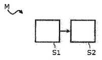
도 8은 본 발명의 또 다른 실시양태에 따른 복합 섬유 부품을 제조하는 공정 순서의 불록도이다.
첨부 도면은 본 발명의 실시양태의 추가적인 이해를 제공하고자 하는 것이다. 이들은 실시양태를 예시하고, 명세서와 함께 본 발명의 원리 및 개념을 설명하는 역할을 한다. 다른 실시양태 및 설명된 많은 이점은 도면과 관련하여 나타날 것이다. 도면 중의 요소는 반드시 서로에 대해 일정한 비율로 축척하여 도시되어 있지는 않다.
달리 명시되지 않는 한, 동일한 작용을 갖고 동일한 효과를 갖는 동일한 요소, 특징부 및 성분은 도면에서 각각 동일한 참조 부호를 붙이고 있다.BRIEF DESCRIPTION OF THE DRAWINGS In the following, the invention will be described in more detail with reference to the embodiments shown in the schematic diagram of the drawings,
1 is a schematic view of a cross-sectional view of a composite fiber component according to an embodiment of the invention;
Figure 2 is a schematic view of a top view of a composite fiber component according to another embodiment of the present invention;
3 is a schematic view of a cross-sectional and plan view of a composite fiber component according to another embodiment of the present invention;
4 is a schematic view of a cross-sectional view of a composite fiber component according to another embodiment of the present invention;
5 is a schematic view of a cross-sectional view of a composite fiber component according to another embodiment of the present invention;
Figure 6 is a schematic view of a cross-sectional view of a composite fiber component according to another embodiment of the present invention;
7 is a schematic view of a cross-sectional view of a composite fiber component according to another embodiment of the present invention;
8 is a block diagram of a process sequence for fabricating a composite fiber component in accordance with another embodiment of the present invention.
The accompanying drawings are intended to provide further understanding of the embodiments of the invention. They serve to illustrate the embodiments and to explain the principles and concepts of the invention with the specification. Other embodiments and many of the advantages described will appear with reference to the drawings. The elements in the figures are not necessarily drawn to scale with respect to each other.
Unless otherwise specified, the same elements, features and components having the same functions and having the same effects are designated by the same reference numerals in the drawings, respectively.
도 1은 복합 섬유 부품(1)을 통한 단면도의 개략도이다. 여기에서, 복합 섬유 부품(1)은 특히 섬유 강화 열가소성 부품일 수 있다. 간편성 때문에, 이하에서 복합 섬유 부품이라는 용어를 섬유 강화 열가소성 부품에 대한 동의어로 사용한다. 복합 섬유 부품(1)은 섬유 강화 반제품, 예를 들면 유기 시트를 포함할 수 있고, 이는 열가소성 매트릭스 재료, 예를 들면 플라스틱 매트릭스 재료 내에 매설되거나 또는 이들 재료에 의해 함침되어 있는 섬유 재료의 하나 이상의 층으로 된 섬유 배열물을 포함한다. 열가소성 매트릭스 재료를 사용함으로써, 복합 섬유 부품(1)은 열 성형 가능하다.1 is a schematic view of a cross section through a
섬유 재료는, 예를 들면, 직조물, 섬유 스트랜드, 편직물, 메쉬, 래티스, 매트 및/또는 부직물 형태의 섬유 배열물을 포함할 수 있다. 여기에서, 래티스는 다축 래티스 또는 일방향 래티스일 수 있다. 또한, 섬유 재료의 섬유는 단섬유, 장섬유 및/또는 연속 섬유일 수 있다. 복합 섬유 부품(1)은, 예를 들면, Twintex®을 포함할 수 있다. 여기에서, 유리 섬유와 같은 강화 섬유를 열가소성 섬유, 예를 들면 폴리프로필렌과 함께 가공하여 조방사를 만들고; 이들을 인터위빙하고, 그 후 가열하고 압력하에서 성형하여 반제품으로 한다.The fibrous material may comprise, for example, fiber arrays in the form of woven fabrics, fiber strands, knitted fabrics, meshes, lattices, mats and / or nonwovens. Here, the lattice may be a multi-axis lattice or a one-way lattice. The fibers of the fiber material may also be short fibers, long fibers and / or continuous fibers. The
복합 섬유 부품(1)에 사용되는 섬유의 섬유 재료는, 예를 들면, 유리 섬유, 아라미드 섬유, 탄소 섬유, 사이잘, 대마, 코코넛 섬유, 면 섬유 및/또는 아마일 수 있다. 여기에서, 섬유는 강성, 강도 및 열 팽창과 관련한 복합 섬유 부품(1)의 요구되는 기계적 특성에 따라 서로에 대해 직각으로 연장될 수 있다. 본원에 개시된 복합 섬유 부품의 실시양태는 언급된 섬유 재료 및 언급된 섬유 가공 형태(예를 들어 직조물, 부직물, 편직물 또는 유사물)에 제한되지 않는다. 여기에서, 복합 섬유 부품(1)은 편평한 반제품으로서 또는 성형된 구조 부품으로서 그의 초기 형태로 제공될 수 있다.The fiber material of the fiber used in the
도 1 중의 복합 섬유 부품(1)은, 열가소성 매트릭스(3)에 의해 함침되어 있는 섬유 재료의 적어도 하나의 층(2)을 포함한다. 열가소성 매트릭스(3)는, 예를 들면, 아크릴로나이트릴 부타다이엔 스타이렌(ABS), 폴리아마이드(PA), 폴리에테르이미드(PEI), 폴리락타이드(PLA), 폴리메틸 메타크릴레이트(PMMA), 폴리카보네이트(PC), 폴리에틸렌 테레프탈레이트(PET), 폴리에틸렌(PE), 폴리프로필렌(PP), 폴리스타이렌(PS), 폴리에테르 에테르 케톤(PEEK), 폴리프로필렌 설파이드(PPS) 또는 폴리비닐 클로라이드(PVC)와 같은 열가소성 수지를 포함할 수 있다.The
복합 섬유 부품(1)은, 서로 인접하여 위치하는, 즉 서로 간격을 두고 있거나 서로 이웃하여 연장되는 두 영역(4 및 5)을 갖는다. 영역(4 및 5)은 이들의 국부 압밀도, 즉 압력 및 열의 적용 후에 이 부품 대역에서 부품이 달성하는 다짐도 및 강도가 본질적으로 서로 다르다. 압밀의 결과로서, 섬유 재료(2)는 매트릭스 재료(3)로 함침되고 압축된다. 압축의 결과로서, 에어 또는 가스 포켓이 섬유 복합체로부터 제거될 수 있다. 이하에서 제 1 영역과 제 2 영역 간의 각각의 경계는 B1 및 B2에 의해, 그리고 일점 쇄선을 사용하여 예시되어 있다. 그러나, 여기에서, 제 1 영역과 제 2 영역 간의 경계선이 반드시 뚜렷하게 분명한 것은 아니고, 압밀도를 본질적으로 계속 변화시키면서 각각의 제 1 영역과 제 2 영역 사이에 중간 영역이 놓일 수도 있다는 것이 명백할 것이다.The
제 1 영역(4)에서는, 복합 섬유 부품(1)의 국부 압밀도가 제 1 압밀 역치 값을 초과하는 한편, 제 2 영역(5)에서의 복합 섬유 부품(1)의 국부 압밀도는 제 2 압밀 역치 미만이다. 여기에서, 제 1 영역(4)에서는 완전하거나 거의 완전한 압밀이 적용될 수 있고 제 2 영역(5)에서는 불완전하거나 부분적인 압밀이 적용될 수 있을 정도로 특히 제 2 압밀 역치 값은 제 1 압밀 역치 값보다 낮다. 예를 들면, 제 2 압밀 역치 값은 제 1 압밀 역치 값의 대략 10% 내지 80%로 설정될 수 있다. 그 결과, 섬유 재료와 매트릭스 재료 간의 밀착성이 선택적으로 조절될 수 있다.In the first region 4, the local density of the
도 1 중의 복합 섬유 부품(1)은, 예를 들면, 제 2 영역(5)에서 필름 힌지를 형성하는 데 사용될 수 있다. 필름 힌지 및 필름 조인트는, 접속될 복합 섬유 부품의 두 부분 사이에 가요성이고 박육인 연접식 홈으로서 설계되는 스트랩 힌지이다. 또한, 제 2 영역(5)에서의 형성 단계, 예를 들면 제 2 영역(5)에서의 복합 섬유 부품(1)의 접힘 또는 굽힘을 단순화하기 위해 제 2 영역(5)에서의 매트릭스 재료의 비율을 감소시킬 수 있다.The
도 2는, 예로서 제 2 영역(5)에 대한 기하학적 설계 가능성을 설명하기 위한, 복합 섬유 부품(1)의 평면도의 개략도이다. 여기에서, 복합 섬유 부품(1)은 도 2에 예로서 도시된 제 2 영역(5) 중 단 하나 또는 일부를 가질 수 있다. 제 2 영역(5)의 양, 및 제 2 영역(5)에 대한 상이한 국지적 기하학의 가능한 조합은, 이 경우 일반적으로 한정되지 않고, 복합 섬유 부품(1)의 원하는 강성 관계에 따라 선택될 수 있다.Fig. 2 is a schematic view of a top view of the
도 2의 맨 왼쪽에는, 스트라이프 형상의 제 2 영역(5)이 도시되어 있는데, 이는 보다 높은 압밀도의 제 1 영역(4)에 의해 분단되어 있다. 그 결과, 예를 들면, 복합 섬유 부품(1)의 음향 거동이 탄성 변형으로 인해 개선될 수 있다. 또한, 이러한 제 2 영역(5)에 의해 진동 및 댐핑 거동이 개선될 수 있다.At the far left of FIG. 2, a stripe-shaped
도 2의 중앙 및 오른쪽에서는, 구불구불하거나 국부적인 영역(5)에서 압밀도가 순서대로 감소하여, 예를 들어, 복합 섬유 부품(1)의 소성 변형의 경우에 증가된 충격 강도를 갖는 영역을 생성하고, 부품에 변형 에너지를 더 잘 흡수할 수 있다.In the center and right of FIG. 2, the compaction in the serpentine or
감소되거나 불완전한 압밀의 제 2 영역(5)은 복합 섬유 부품의 힘 도입 영역에 사용하는 데 특히 적합하며, 이것의 3가지 예가 도 3, 도 4 및 도 5에 도시되어 있다. 도 3은 감소된 압밀도의 제 2 영역(5)의 내측에 위치하는 힘 도입 영역(6)을 갖는 복합 섬유 부품(1)의 평면도(A)의 개략도이다. 여기에서, 제 2 영역(4)은 힘 도입 영역(6) 주위의 원형 또는 타원형 영역을 구성한다. 평면도(A)의 복합 섬유 부품(1)의 단면도(B)에 도시된 바와 같이, 스크류 보스(7)는 힘 도입 영역(6) 상에 형성되어 있고, 제 2 영역(5)에서의 감소된 압밀도의 결과로서 복합 섬유 부품(1) 내로의 보다 완만한 힘 도입을 가능하게 한다. 또한, 스크류 보스(7)는 결과적으로 과부하로부터 더 잘 보호된다.The
도 4는 감소된 압밀도의 제 2 영역(5)의 내측에 위치하는 힘 도입 영역(6)을 갖는 복합 섬유 부품(1)의 단면도이다. 도 4 중의 힘 도입 영역(6)은 결합 지점( 8)이며, 이 지점에서 결합 매체(8a)를 사용하여 결합 상대(8b)가 복합 섬유 부품(1)에 부착된다. 감소된 압밀도의 제 2 영역(5)의 결과로서, 결합 매체(8a)가 개선된 반응 표면을 얻을 정도로 복합 섬유 부품(1)의 표면이 확대된다. 또한, 제 2 영역(5)에서의 감소된 압밀도의 결과로서, 결합 지점(8)의 영역에서 복합 섬유 부품(1) 내로의 보다 완만한 힘 도입이 용이하게 된다.4 is a cross-sectional view of the
도 5는 감소된 압밀도의 제 2 영역(5)의 내측에 위치하는 힘 도입 영역(6)을 포함하는 복합 섬유 부품(1)의 단면도이다. 도 5 중의 힘 도입 영역(6)은 스크류 접속 지점(9)이며 이 지점에서 스크류 접속부가 복합 섬유 부품(1) 내로 도입된다. 감소된 압밀도의 제 2 영역(5)의 결과로서, 스크류 접속 지점(9)의 영역에서 보다 양호한 힘 도입이 가능할 정도로 복합 섬유 부품(1)의 이용 가능한 부품 두께가 국부적으로 증가한다. 또한, 제 2 영역(5)에서의 감소된 압밀도의 결과로서, 스크류 접속 지점(9)에서 복합 섬유 부품(1) 내로의 보다 완만한 힘 도입이 용이하게 된다.5 is a cross-sectional view of a
도 4 및 도 5와 유사한 방법으로, 리베팅 지점 또는 용접 지점도 또한 형성될 수 있다. 용접 지점의 경우, 연속 섬유가, 불완전하게 압밀된 영역(5)에서 목표하는 방식으로 용접 대역 내로 밀어넣어질 수 있다는 이점을 또한 나타낸다.In a similar manner to Figs. 4 and 5, a re-betting spot or welding spot may also be formed. In the case of welding points, it also shows the advantage that the continuous fibers can be pushed into the weld zone in a targeted manner in the incompletely
도 6은 연장 방향으로 상이한 양의 섬유층(2)을 포함하는 복합 섬유 부품(1)의 개략도이다. 국부 강화층을 만들 수 있도록 하기 위해, 예를 들면 오른쪽으로부터 왼쪽으로 층의 양이 증가한다. 새로운 강화층이 시작되는 각 대역에서는, 복합 섬유 부품(1) 전체의 강성이 국부적으로 갑자기 상승한다. 강성의 급상승의 정도를 감소시키기 위해, 제 1 양의 섬유층(2a)을 갖는 대역에 제 1 영역(4)이 형성될 수 있다. 이 제 1 영역(4)은 제 1 양의 섬유층(2a)보다 높은 제 2 양의 섬유층(2b)을 포함하는 제 2 영역(5)에 직접 인접한다. 이때 제 2 영역(5)이 제 1 영역에 비해 국부적으로 감소된 압밀도를 포함하면, 복합 섬유 부품(1)의 강성은 단지 점진적으로 증가할 뿐이고, 그 결과, 강성의 상승이 복합 섬유 부품(1) 전체에 걸쳐 보다 원활하게 확장된다. 또한, 개개의 층 전이부 사이의 노치 효과 또는 응력 집중 인자가 감소한다.6 is a schematic view of a
도 7은 제 3 영역(5a), 예를 들면 복합 섬유 부품(1)의 단부에 매트릭스 재료(3)를 갖지 않는, 즉 블랭크, 미함침 또는 미습윤 섬유를 갖는 복합 섬유 부품(1)의 평면도의 개략도이다. 상기 제 3 영역(5a)은 감소된 압밀도의 제 2 영역(5)에 인접할 수 있고, 제 2 영역(5)은 제 1 영역(4)과 제 3 영역(5a) 사이에 배열되어 있다. 이러한 제 3 영역(5a)은, 예를 들면, 복합 섬유 부품의 조인트에 사용되고 이 조인트는 결합에 의해 블랭크 섬유의 영역 내에 있는 다른 조인트 상대에 접속된다. 제 1 영역(4)으로부터 제 2 영역(5)을 지나 제 3 영역(5a)까지 압밀도가 점진적으로 감소함으로써 섬유 내로의 최적의 힘 도입이 확보될 수 있다.7 is a plan view of the
도 1 내지 도 7에 도시된 복합 섬유 부품은, 예를 들면, 열가소성 재료를 사출하기 위한 사출 성형 도구의 사출 금형에 의해 제조될 수 있다. 이 공정에서는, 예를 들면 유기 시트 또는 예비압밀된 시트, 예를 들면 Twintex® 시트 또는 이러한 시트의 층들의 적층물이 사용될 수 있으며, 상기 시트는 플라스틱 매트릭스의 가공 온도까지 반제품 또는 예비형성된 부품으로서 가열되고, 사출 성형 도구의 사출 금형 내에 놓일 수 있다. 박육 복합 섬유 부품의 경우에는, 가열이 사출 금형 내에서 일어날 수도 있다.The composite fiber component shown in Figs. 1 to 7 can be manufactured, for example, by an injection mold of an injection molding tool for injecting a thermoplastic material. In this process, for example, an organic sheet or a pre-consolidated sheet such as a Twintex® sheet or a laminate of layers of such a sheet can be used, And can be placed in the injection mold of the injection molding tool. In the case of thin-walled composite fiber components, heating may occur in the injection mold.
사출 금형 내에 수용된 반제품 또는 예비형성된 부품은 적절한 가공 온도까지 가열되는데, 마찬가지로 적절히 가열된 유체 열가소성 매트릭스 재료가 사출 금형 내로 사출될 수 있을 정도로 가열된다. 이 공정에서, 사출되는 매트릭스 재료는, 예를 들면, 사용되는 유기 시트의 매트릭스 재료(3)와 동일한 재료일 수 있다. 대안으로, 반제품 또는 예비형성된 부품의 열가소성 매트릭스 재료(3)와 조합될 수 있는 상이한 열가소성 재료가 사출될 수도 있다.The semi-finished or preformed part contained within the injection mold is heated to an appropriate processing temperature, likewise heated to such an extent that a properly heated fluid thermoplastic matrix material can be injected into the injection mold. In this process, the injected matrix material may be the same material as the matrix material 3 of the organic sheet used, for example. Alternatively, different thermoplastic materials that can be combined with the thermoplastic matrix material 3 of semi-finished or pre-formed parts may be injected.
사출 성형 도구 대신에, 압출 도구 또는 또 다른 적합한 도구가 사용될 수 있다. 그러나, 본 발명은 사출 성형 및 압출에 한정되지 않는다.Instead of an injection molding tool, an extrusion tool or another suitable tool may be used. However, the present invention is not limited to injection molding and extrusion.
도 8은 복합 섬유 부품, 예를 들면 도 1 내지 도 7 중 어느 것에 도시된 복합 섬유 부품(1) 중 하나를 제조하는 방법(M)의 블록도이다. 방법(M)은 사출 성형 또는 압출 공정의 범위 내에서 사용될 수 있다. 제 1 단계(S1)에서는, 섬유 재료의 적어도 하나의 층(2) 및 섬유 재료를 함침하는 열가소성 매트릭스(3)를 갖는 섬유 강화 반제품, 예를 들면 유기 시트 또는 유기 시트 적층물의 제 1 영역(4)의 압밀이 일어난다. 이 압밀은 제 1 압밀도까지 수행된다. 동시에 또는 연속해서, 제 1 영역(4)에 인접하여 위치하는, 즉 제 1 영역(4)과 간격을 두고 있거나 이웃하고 있는, 섬유 강화 반제품의 제 2 영역(5)의 압밀이, 제 1 압밀도와는 다른 제 2 압밀도까지 단계 2에서 일어난다. 여기에서, 제 2 영역(5)이 제 1 영역(4)에 비해 충분히 압밀되지 않을 정도로, 즉 제 1 영역(4)과 동일한 정도로 경화되고 다져지지 않을 정도로, 제 2 압밀도는 제 1 압밀도보다 낮다. 예를 들면, 제 2 압밀도는 제 1 압밀도의 10% 내지 80%일 수 있다.Fig. 8 is a block diagram of a method M for producing one of the composite fiber components, for example one of the
단계 S1과 S2의 상이한 압밀은, 예를 들면, 섬유 강화 반제품에 제 2 영역(5)에서 적용되는 제 2 압밀 압력보다, 제 1 영역(4)에서 섬유 강화 반제품에 적용되는 제 1 압밀 압력이 높은 것에 의해 달성될 수 있다. 대안으로 또는 부가적으로, 상이한 압밀도를 달성하기 위해 제 2 영역(5)에 압밀 압력이 적용되는 시간의 길이를 제 1 영역(4)에 압밀 압력이 적용되는 시간의 길이에 비해 감소시킬 수도 있다. 궁국적으로, 제 2 영역(5)에서 보다 낮은 압밀도를 가능하게 하기 위해 제 1 영역(4)에 비해 제 2 영역(5)에서 매트릭스 재료의 비율을 감소시키는 것도 또한 가능하다.The different consolidation of steps S1 and S2 can be achieved, for example, by applying a first consolidation pressure applied to the fiber-reinforced semi-finished product in the first zone 4 to a second consolidation pressure applied in the
이상, 본 발명을 바람직한 실시양태를 참조하여 충분히 설명하였지만, 본 발명은 이에 제한되는 것은 아니고, 다양한 방식으로 변형될 수 있다. 특히, 위에 개별적으로 설명된 실시양태들의 개개의 특징은, 달리 명시되지 않는 한, 서로 조합될 수도 있다.While the present invention has been fully described with reference to the preferred embodiments thereof, the present invention is not limited thereto and can be modified in various ways. In particular, the individual features of the embodiments individually described above may be combined with one another, unless otherwise specified.
1: 복합 섬유 부품
2: 섬유층
2a: 섬유층
2b: 섬유층
3: 열가소성 매트릭스
4: 제 1 영역
5: 제 2 영역
5a: 제 3 영역
6: 힘 도입 영역
7: 스크류 보스
8: 결합 지점
8a: 결합 매체
8b: 결합 상대
9: 스크류 접속 지점
B1: 영역 간의 경계
B2: 영역 간의 경계
M: 방법
S1: 방법 단계
S2: 방법 단계1: Composite fiber parts
2: fibrous layer
2a: fibrous layer
2b: fibrous layer
3: Thermoplastic matrix
4: first region
5: second region
5a: third region
6: force introduction area
7: Screw boss
8: Coupling point
8a: Coupling medium
8b: joining partner
9: Screw connection point
B1: boundary between regions
B2: boundary between regions
M: How
S1: Method Step
S2: Method steps
Claims (13)
Translated fromKorean섬유 재료를 함침하는 열가소성 매트릭스(3)
를 포함하는 복합 섬유 부품(1)으로서,
상기 복합 섬유 부품(1)은, 복합 섬유 부품(1)의 국부 압밀도(local degree of consolidation)가 미리 설정된 제 1 압밀 역치를 초과하는 적어도 하나의 제 1 영역(4)을 갖고, 또한
상기 복합 섬유 부품(1)은, 제 1 영역(4)에 인접하여 있고 복합 섬유 부품(1)의 국부 압밀도가 미리 설정된 제 2 압밀 역치 미만인 적어도 하나의 제 2 영역(5)을 가지며,
제 2 압밀 역치가 제 1 압밀 역치보다 낮고,
제 1 영역(4)이 제 1 양의 섬유층(2a)을 갖고, 제 2 영역(5)이 제 1 양의 섬유층(2a)보다 높은 제 2 양의 섬유층(2b)을 갖는
복합 섬유 부품(1).At least one layer (2) of fibrous material; And
Thermoplastic matrices for impregnation of textile materials (3)
A composite fiber component (1) comprising:
The composite fiber component 1 has at least one first region 4 in which the local degree of consolidation of the composite fiber component 1 exceeds a preset first consolidation threshold,
The composite fiber component 1 has at least one second region 5 adjacent to the first region 4 and having a local compaction density of the composite fiber component 1 less than a preset second compaction threshold,
The second consolidation threshold is lower than the first consolidation threshold,
The first region 4 has the first positive fibrous layer 2a and the second region 5 has the second positive fibrous layer 2b higher than the first positive fibrous layer 2a
Composite fiber parts (1).
제 2 압밀 역치가 제 1 압밀 역치의 10% 내지 80%인 복합 섬유 부품(1).The method according to claim 1,
And the second consolidation threshold is between 10% and 80% of the first consolidation threshold.
제 2 영역(5)이 필름 힌지를 구성하는 복합 섬유 부품(1).3. The method according to claim 1 or 2,
A composite fiber component (1) in which a second region (5) constitutes a film hinge.
힘 도입 영역(6)을 더 포함하고,
제 2 영역(5)이 힘 도입 영역(6) 주위의 원형 또는 타원형 영역을 구성하는
복합 섬유 부품(1).3. The method according to claim 1 or 2,
Further comprising a force introduction region (6)
The second region 5 constitutes a circular or elliptical region around the force introduction region 6
Composite fiber parts (1).
힘 도입 영역(6)이 결합 지점(8), 리베팅 지점, 용접 지점, 스크류 접속 지점 (9) 또는 스크류 보스(7)를 구성하는 복합 섬유 부품(1).5. The method of claim 4,
A composite fiber component (1) wherein the force introduction area (6) constitutes a coupling point (8), a re-betting point, a welding point, a screw connection point (9) or a screw boss (7).
열가소성 매트릭스(3)에 의해 함침되지 않은 섬유 재료의 층(2)을 갖는 제 3 영역(5a)을 더 포함하고,
제 2 영역(5)이 제 1 영역(4)과 제 3 영역(5a) 사이에 배열되어 있는 복합 섬유 부품(1).3. The method according to claim 1 or 2,
Further comprising a third zone (5a) having a layer (2) of fibrous material not impregnated by the thermoplastic matrix (3)
And the second region (5) is arranged between the first region (4) and the third region (5a).
섬유 재료가 유리 섬유, 아라미드 섬유, 탄소 섬유, 사이잘, 대마, 코코넛 섬유, 면 섬유 및/또는 아마의 섬유 배열물로 형성되고,
섬유 배열물이 직조물, 섬유 스트랜드, 편직물, 메쉬, 래티스, 매트 및/또는 부직물인 복합 섬유 부품(1).3. The method according to claim 1 or 2,
Wherein the fiber material is formed from a fiber array of glass fibers, aramid fibers, carbon fibers, sisal, hemp, coconut fibers, cotton fibers and / or flax,
Composite fiber component (1) wherein the fiber array is a woven material, a fiber strand, a knitted fabric, a mesh, a lattice, a mat and / or a nonwoven.
복합 섬유 부품(1)이 연속 섬유 강화 복합 섬유 부품(1)인 복합 섬유 부품(1).3. The method according to claim 1 or 2,
Composite fiber component (1) is a continuous fiber reinforced composite fiber component (1).
복합 섬유 부품(1)이 적어도 하나의 유기 시트 또는 예비압밀된 시트를 갖는 복합 섬유 부품(1).3. The method according to claim 1 or 2,
A composite fiber component (1) having at least one organic sheet or pre-consolidated sheet.
제 1 영역(4)에 인접하여 있는, 섬유 강화 반제품의 제 2 영역(5)을, 제 1 압밀도와는 다른 제 2 압밀도까지 압밀(S2)하는 것을 포함하며,
제 2 압밀도가 제 1 압밀도보다 낮고,
제 1 영역(4)이 제 1 양의 섬유층(2a)을 갖고, 제 2 영역(5)이 제 1 양의 섬유층(2a)보다 높은 제 2 양의 섬유층(2b)을 갖는
복합 섬유 부품(1)의 제조 방법(M).(S1) of a fiber-reinforced semi-finished product having at least one layer (2) of a fiber material and a thermoplastic matrix (3) impregnating the fiber material to a first compaction density;
Tightening the second region 5 of the fiber-reinforced semi-finished product adjacent to the first region 4 to a second compaction density different from the first compaction density (S2)
The second compaction density is lower than the first compaction density,
The first region 4 has the first positive fibrous layer 2a and the second region 5 has the second positive fibrous layer 2b higher than the first positive fibrous layer 2a
Method for manufacturing composite fiber part (1) (M).
제 2 압밀도가 제 1 압밀도의 10% 내지 80%인 방법(M).12. The method of claim 11,
And the second compaction is between 10% and 80% of the first compaction.
제 1 영역(4)의 압밀(S1)은, 섬유 강화 반제품에 제 1 압밀 압력을 적용하는 것을 포함하고, 제 2 영역(5)의 압밀(S2)은, 섬유 강화 반제품에 제 1 압밀 압력보다 낮은 제 2 압밀 압력을 적용하는 것을 포함하는 방법(M).13. The method according to claim 11 or 12,
The consolidation S1 of the first zone 4 comprises applying a first consolidation pressure to the fiber reinforced semi-finished product and the consolidation S2 of the second zone 5 comprises applying the first consolidation pressure to the fiber- A method (M) comprising applying a low second consolidation pressure.
Applications Claiming Priority (3)
| Application Number | Priority Date | Filing Date | Title |
|---|---|---|---|
| DE102014205861.9 | 2014-03-28 | ||
| DE102014205861.9ADE102014205861A1 (en) | 2014-03-28 | 2014-03-28 | Fiber composite component and method for producing a fiber composite component |
| PCT/EP2015/056045WO2015144612A2 (en) | 2014-03-28 | 2015-03-23 | Composite fiber component and method for producing a composite fiber component |
Related Child Applications (1)
| Application Number | Title | Priority Date | Filing Date |
|---|---|---|---|
| KR1020197004713ADivisionKR102047752B1 (en) | 2014-03-28 | 2015-03-23 | Composite fiber component and method for producing a composite fiber component |
Publications (2)
| Publication Number | Publication Date |
|---|---|
| KR20160145632A KR20160145632A (en) | 2016-12-20 |
| KR101995848B1true KR101995848B1 (en) | 2019-07-03 |
Family
ID=52737095
Family Applications (2)
| Application Number | Title | Priority Date | Filing Date |
|---|---|---|---|
| KR1020197004713AActiveKR102047752B1 (en) | 2014-03-28 | 2015-03-23 | Composite fiber component and method for producing a composite fiber component |
| KR1020167030171AActiveKR101995848B1 (en) | 2014-03-28 | 2015-03-23 | Composite fiber component and method for producing a composite fiber component |
Family Applications Before (1)
| Application Number | Title | Priority Date | Filing Date |
|---|---|---|---|
| KR1020197004713AActiveKR102047752B1 (en) | 2014-03-28 | 2015-03-23 | Composite fiber component and method for producing a composite fiber component |
Country Status (7)
| Country | Link |
|---|---|
| US (1) | US20170174850A1 (en) |
| EP (1) | EP3122543B1 (en) |
| KR (2) | KR102047752B1 (en) |
| CN (1) | CN106573420B (en) |
| DE (1) | DE102014205861A1 (en) |
| PL (1) | PL3122543T3 (en) |
| WO (1) | WO2015144612A2 (en) |
Families Citing this family (2)
| Publication number | Priority date | Publication date | Assignee | Title |
|---|---|---|---|---|
| DE102021107363A1 (en) | 2021-03-24 | 2022-09-29 | Delcotex Delius Techtex Gmbh & Co. Kg | Textile fabric and its use as well as method for its production |
| US11766840B2 (en)* | 2021-08-30 | 2023-09-26 | The Boeing Company | Apparatus and method to enable in-plane bending of high contour composite structures in post-forming operations |
Citations (3)
| Publication number | Priority date | Publication date | Assignee | Title |
|---|---|---|---|---|
| JP2002240566A (en) | 2001-02-21 | 2002-08-28 | Nissan Motor Co Ltd | Vehicle resin panel and method of manufacturing vehicle resin panel |
| WO2002081189A1 (en) | 2001-04-03 | 2002-10-17 | Structural Polymer Systems Limited | Bonding material for gel coat applications |
| US20130241108A1 (en)* | 2010-09-10 | 2013-09-19 | Johnson Controls Gmbh | Method for producing a rear wall of a seat back |
Family Cites Families (13)
| Publication number | Priority date | Publication date | Assignee | Title |
|---|---|---|---|---|
| JPS6224039A (en)* | 1985-07-24 | 1987-02-02 | Nhk Spring Co Ltd | Leaf spring made of fiber-reinforced resin |
| GB8527023D0 (en)* | 1985-11-01 | 1985-12-04 | Wiggins Teape Group Ltd | Moulded fibre reinforced plastic articles |
| DE19531406A1 (en)* | 1995-08-26 | 1997-02-27 | Borgers Johann Gmbh Co Kg | Semi-finished sheets of fibrous material and binder for fabricating pressed shaped parts |
| FR2768076B1 (en)* | 1997-09-10 | 2000-08-04 | Peguform France | METHOD FOR PRODUCING A RIGIDIFIED ZONE INSERT FORMING IN A COMPOSITE SANDWICH PANEL, AND PANEL COMPRISING SUCH A ZONE |
| DE10356185A1 (en)* | 2002-12-10 | 2004-06-24 | Sumitomo Chemical Co., Ltd. | Fiber-resin composite comprises fibers aligned parallel in a blend of a polypropylene resin and a modified polyolefin resin |
| DK1603735T3 (en)* | 2003-03-06 | 2007-07-09 | Vestas Wind Sys As | Compound between composites with incompatible properties and method of manufacture |
| DE102010013713A1 (en)* | 2010-04-02 | 2011-10-06 | Airbus Operations Gmbh | Method and apparatus for producing a fiber-reinforced thermoplastic composite component |
| DE102010050065B4 (en)* | 2010-10-29 | 2015-10-01 | Ifc Composite Gmbh | Leaf spring made of a fiber composite material with different lengths of fiber layers and process for their preparation |
| CN102408685B (en)* | 2011-08-31 | 2013-06-26 | 上海锦湖日丽塑料有限公司 | Glass fiber reinforced PBT resin with high weather resistance and preparation method thereof |
| DE102011056686B4 (en) | 2011-12-20 | 2017-11-23 | Markus Brzeski | A process for producing a fiber composite material, a fiber composite produced by the process and an apparatus for carrying out the process |
| DE102012006034A1 (en)* | 2012-03-27 | 2013-10-02 | Mbb Fertigungstechnik Gmbh | Method for producing a substantially cup-shaped, fiber-reinforced plastic part |
| DE102012104044A1 (en) | 2012-05-09 | 2013-11-14 | Rehau Ag + Co | Method for at least partially consolidating a preform for producing a molded part in a mold |
| DE102012104316A1 (en)* | 2012-05-18 | 2013-11-21 | Institut Für Verbundwerkstoffe Gmbh | Method for manufacturing fiber composite material component using shaping tool, involves pressurizing semi-finished material such that component different structures are set with different mechanical properties over component thickness |
- 2014
- 2014-03-28DEDE102014205861.9Apatent/DE102014205861A1/ennot_activeCeased
- 2015
- 2015-03-23CNCN201580028037.8Apatent/CN106573420B/enactiveActive
- 2015-03-23KRKR1020197004713Apatent/KR102047752B1/enactiveActive
- 2015-03-23EPEP15712113.8Apatent/EP3122543B1/enactiveActive
- 2015-03-23PLPL15712113Tpatent/PL3122543T3/enunknown
- 2015-03-23USUS15/129,700patent/US20170174850A1/ennot_activeAbandoned
- 2015-03-23WOPCT/EP2015/056045patent/WO2015144612A2/enactiveApplication Filing
- 2015-03-23KRKR1020167030171Apatent/KR101995848B1/enactiveActive
Patent Citations (3)
| Publication number | Priority date | Publication date | Assignee | Title |
|---|---|---|---|---|
| JP2002240566A (en) | 2001-02-21 | 2002-08-28 | Nissan Motor Co Ltd | Vehicle resin panel and method of manufacturing vehicle resin panel |
| WO2002081189A1 (en) | 2001-04-03 | 2002-10-17 | Structural Polymer Systems Limited | Bonding material for gel coat applications |
| US20130241108A1 (en)* | 2010-09-10 | 2013-09-19 | Johnson Controls Gmbh | Method for producing a rear wall of a seat back |
Also Published As
| Publication number | Publication date |
|---|---|
| KR20190018769A (en) | 2019-02-25 |
| CN106573420B (en) | 2019-12-20 |
| WO2015144612A2 (en) | 2015-10-01 |
| EP3122543A2 (en) | 2017-02-01 |
| CN106573420A (en) | 2017-04-19 |
| KR102047752B1 (en) | 2019-11-22 |
| EP3122543B1 (en) | 2021-06-23 |
| DE102014205861A1 (en) | 2015-10-01 |
| WO2015144612A3 (en) | 2015-12-23 |
| US20170174850A1 (en) | 2017-06-22 |
| PL3122543T3 (en) | 2021-09-27 |
| KR20160145632A (en) | 2016-12-20 |
Similar Documents
| Publication | Publication Date | Title |
|---|---|---|
| JP7201579B2 (en) | planar composite | |
| US5753062A (en) | Fibre reinforced thermoplastic sheet | |
| CN104159720B (en) | The production method of automotive component and corresponding parts | |
| US20130127092A1 (en) | Moulded multilayer plastics component with continuously reinforced fibre plies and process for producing this component | |
| US20100032870A1 (en) | Method for the production of fiber-reinforced polypropylene molded parts containing pores | |
| WO2016166218A1 (en) | Light weight engine mounted trim part | |
| WO2004059063A2 (en) | Thermoplastic formed panel, intermediate panel for the fabrication thereof, and method for fabricating said panel and said intermediate panel | |
| JP6190064B2 (en) | Manufacturing method of composite molded body, composite molded body, sandwich component, rotor blade element, and wind power generator | |
| CN104602897B (en) | Functionally optimized fiber composite component and method of making the same | |
| KR101995848B1 (en) | Composite fiber component and method for producing a composite fiber component | |
| US20220143879A1 (en) | Dual expanding foam for closed mold composite manufacturing | |
| KR102358826B1 (en) | Production of multishell composite-material components with reinforcement structure bonded thereto | |
| KR100824695B1 (en) | Lightweight laminated sheet and its manufacturing method | |
| KR102349669B1 (en) | Forming method of fiber reinforced plastic material | |
| JP7153801B2 (en) | Method for preparing sandwich-like composite material | |
| CN105121140A (en) | Process for thermoplastic material comprising fiber reinforcement and resulting product | |
| WO2024173586A1 (en) | Multilayer composite heat shield | |
| CN118457454A (en) | Fiber composite material product and method for manufacturing the same | |
| KR20130062472A (en) | A method of plastic board with ultra-lightweight | |
| RU2021105519A (en) | REINFORCING TAPE FIBER MATERIAL AND METHOD FOR ITS MANUFACTURE, BODY LAYERED WITH REINFORCING FIBER AND MOLDED BODY FROM FIBER-REINFORCED RESIN USING REINFORCING TAPE FIBER MATERIAL | |
| JP2007530810A (en) | Reinforcing materials, reinforcing laminates, and composite materials having these |
Legal Events
| Date | Code | Title | Description |
|---|---|---|---|
| PA0105 | International application | Patent event date:20161027 Patent event code:PA01051R01D Comment text:International Patent Application | |
| A201 | Request for examination | ||
| PA0201 | Request for examination | Patent event code:PA02012R01D Patent event date:20161123 Comment text:Request for Examination of Application | |
| PG1501 | Laying open of application | ||
| E902 | Notification of reason for refusal | ||
| PE0902 | Notice of grounds for rejection | Comment text:Notification of reason for refusal Patent event date:20171217 Patent event code:PE09021S01D | |
| E902 | Notification of reason for refusal | ||
| PE0902 | Notice of grounds for rejection | Comment text:Notification of reason for refusal Patent event date:20180627 Patent event code:PE09021S01D | |
| E902 | Notification of reason for refusal | ||
| PE0902 | Notice of grounds for rejection | Comment text:Notification of reason for refusal Patent event date:20181224 Patent event code:PE09021S01D | |
| A107 | Divisional application of patent | ||
| PA0104 | Divisional application for international application | Comment text:Divisional Application for International Patent Patent event code:PA01041R01D Patent event date:20190218 | |
| E701 | Decision to grant or registration of patent right | ||
| PE0701 | Decision of registration | Patent event code:PE07011S01D Comment text:Decision to Grant Registration Patent event date:20190425 | |
| GRNT | Written decision to grant | ||
| PR0701 | Registration of establishment | Comment text:Registration of Establishment Patent event date:20190627 Patent event code:PR07011E01D | |
| PR1002 | Payment of registration fee | Payment date:20190628 End annual number:3 Start annual number:1 | |
| PG1601 | Publication of registration | ||
| PR1001 | Payment of annual fee | Payment date:20220517 Start annual number:4 End annual number:4 | |
| PR1001 | Payment of annual fee | Payment date:20240522 Start annual number:6 End annual number:6 |