KR101994739B1 - Wireless power transmitting apparatus and wireless power transmitting methid - Google Patents
Wireless power transmitting apparatus and wireless power transmitting methidDownload PDFInfo
- Publication number
- KR101994739B1 KR101994739B1KR1020140115661AKR20140115661AKR101994739B1KR 101994739 B1KR101994739 B1KR 101994739B1KR 1020140115661 AKR1020140115661 AKR 1020140115661AKR 20140115661 AKR20140115661 AKR 20140115661AKR 101994739 B1KR101994739 B1KR 101994739B1
- Authority
- KR
- South Korea
- Prior art keywords
- wireless power
- receiving apparatus
- transmission
- transmission coil
- power receiving
- Prior art date
- Legal status (The legal status is an assumption and is not a legal conclusion. Google has not performed a legal analysis and makes no representation as to the accuracy of the status listed.)
- Active
Links
- 230000005540biological transmissionEffects0.000claimsabstractdescription119
- 238000000034methodMethods0.000claimsabstractdescription18
- 238000004891communicationMethods0.000claimsabstractdescription14
- 230000004907fluxEffects0.000claims1
- 238000010586diagramMethods0.000description6
- 238000013461designMethods0.000description5
- 230000000694effectsEffects0.000description3
- 230000006698inductionEffects0.000description3
- 238000001646magnetic resonance methodMethods0.000description2
- 238000010561standard procedureMethods0.000description2
- 230000002159abnormal effectEffects0.000description1
- 238000007792additionMethods0.000description1
- 230000003247decreasing effectEffects0.000description1
- 238000012986modificationMethods0.000description1
- 230000004048modificationEffects0.000description1
- 238000006467substitution reactionMethods0.000description1
Images


Classifications
- H—ELECTRICITY
- H02—GENERATION; CONVERSION OR DISTRIBUTION OF ELECTRIC POWER
- H02J—CIRCUIT ARRANGEMENTS OR SYSTEMS FOR SUPPLYING OR DISTRIBUTING ELECTRIC POWER; SYSTEMS FOR STORING ELECTRIC ENERGY
- H02J50/00—Circuit arrangements or systems for wireless supply or distribution of electric power
- H02J50/40—Circuit arrangements or systems for wireless supply or distribution of electric power using two or more transmitting or receiving devices
- H—ELECTRICITY
- H02—GENERATION; CONVERSION OR DISTRIBUTION OF ELECTRIC POWER
- H02J—CIRCUIT ARRANGEMENTS OR SYSTEMS FOR SUPPLYING OR DISTRIBUTING ELECTRIC POWER; SYSTEMS FOR STORING ELECTRIC ENERGY
- H02J13/00—Circuit arrangements for providing remote indication of network conditions, e.g. an instantaneous record of the open or closed condition of each circuitbreaker in the network; Circuit arrangements for providing remote control of switching means in a power distribution network, e.g. switching in and out of current consumers by using a pulse code signal carried by the network
- H02J13/00006—Circuit arrangements for providing remote indication of network conditions, e.g. an instantaneous record of the open or closed condition of each circuitbreaker in the network; Circuit arrangements for providing remote control of switching means in a power distribution network, e.g. switching in and out of current consumers by using a pulse code signal carried by the network characterised by information or instructions transport means between the monitoring, controlling or managing units and monitored, controlled or operated power network element or electrical equipment
- H02J13/00022—Circuit arrangements for providing remote indication of network conditions, e.g. an instantaneous record of the open or closed condition of each circuitbreaker in the network; Circuit arrangements for providing remote control of switching means in a power distribution network, e.g. switching in and out of current consumers by using a pulse code signal carried by the network characterised by information or instructions transport means between the monitoring, controlling or managing units and monitored, controlled or operated power network element or electrical equipment using wireless data transmission
- H02J13/00026—Circuit arrangements for providing remote indication of network conditions, e.g. an instantaneous record of the open or closed condition of each circuitbreaker in the network; Circuit arrangements for providing remote control of switching means in a power distribution network, e.g. switching in and out of current consumers by using a pulse code signal carried by the network characterised by information or instructions transport means between the monitoring, controlling or managing units and monitored, controlled or operated power network element or electrical equipment using wireless data transmission involving a local wireless network, e.g. Wi-Fi, ZigBee or Bluetooth
- H—ELECTRICITY
- H02—GENERATION; CONVERSION OR DISTRIBUTION OF ELECTRIC POWER
- H02J—CIRCUIT ARRANGEMENTS OR SYSTEMS FOR SUPPLYING OR DISTRIBUTING ELECTRIC POWER; SYSTEMS FOR STORING ELECTRIC ENERGY
- H02J50/00—Circuit arrangements or systems for wireless supply or distribution of electric power
- H02J50/005—Mechanical details of housing or structure aiming to accommodate the power transfer means, e.g. mechanical integration of coils, antennas or transducers into emitting or receiving devices
- H—ELECTRICITY
- H02—GENERATION; CONVERSION OR DISTRIBUTION OF ELECTRIC POWER
- H02J—CIRCUIT ARRANGEMENTS OR SYSTEMS FOR SUPPLYING OR DISTRIBUTING ELECTRIC POWER; SYSTEMS FOR STORING ELECTRIC ENERGY
- H02J50/00—Circuit arrangements or systems for wireless supply or distribution of electric power
- H02J50/60—Circuit arrangements or systems for wireless supply or distribution of electric power responsive to the presence of foreign objects, e.g. detection of living beings
- H—ELECTRICITY
- H02—GENERATION; CONVERSION OR DISTRIBUTION OF ELECTRIC POWER
- H02J—CIRCUIT ARRANGEMENTS OR SYSTEMS FOR SUPPLYING OR DISTRIBUTING ELECTRIC POWER; SYSTEMS FOR STORING ELECTRIC ENERGY
- H02J50/00—Circuit arrangements or systems for wireless supply or distribution of electric power
- H02J50/80—Circuit arrangements or systems for wireless supply or distribution of electric power involving the exchange of data, concerning supply or distribution of electric power, between transmitting devices and receiving devices
- H—ELECTRICITY
- H02—GENERATION; CONVERSION OR DISTRIBUTION OF ELECTRIC POWER
- H02J—CIRCUIT ARRANGEMENTS OR SYSTEMS FOR SUPPLYING OR DISTRIBUTING ELECTRIC POWER; SYSTEMS FOR STORING ELECTRIC ENERGY
- H02J50/00—Circuit arrangements or systems for wireless supply or distribution of electric power
- H02J50/90—Circuit arrangements or systems for wireless supply or distribution of electric power involving detection or optimisation of position, e.g. alignment
- H—ELECTRICITY
- H02—GENERATION; CONVERSION OR DISTRIBUTION OF ELECTRIC POWER
- H02J—CIRCUIT ARRANGEMENTS OR SYSTEMS FOR SUPPLYING OR DISTRIBUTING ELECTRIC POWER; SYSTEMS FOR STORING ELECTRIC ENERGY
- H02J7/00—Circuit arrangements for charging or depolarising batteries or for supplying loads from batteries
- H02J7/007—Regulation of charging or discharging current or voltage
- H02J7/0071—Regulation of charging or discharging current or voltage with a programmable schedule
- H—ELECTRICITY
- H04—ELECTRIC COMMUNICATION TECHNIQUE
- H04B—TRANSMISSION
- H04B5/00—Near-field transmission systems, e.g. inductive or capacitive transmission systems
- H04B5/20—Near-field transmission systems, e.g. inductive or capacitive transmission systems characterised by the transmission technique; characterised by the transmission medium
- H04B5/24—Inductive coupling
- H04B5/26—Inductive coupling using coils
- H04B5/263—Multiple coils at either side
- Y—GENERAL TAGGING OF NEW TECHNOLOGICAL DEVELOPMENTS; GENERAL TAGGING OF CROSS-SECTIONAL TECHNOLOGIES SPANNING OVER SEVERAL SECTIONS OF THE IPC; TECHNICAL SUBJECTS COVERED BY FORMER USPC CROSS-REFERENCE ART COLLECTIONS [XRACs] AND DIGESTS
- Y02—TECHNOLOGIES OR APPLICATIONS FOR MITIGATION OR ADAPTATION AGAINST CLIMATE CHANGE
- Y02B—CLIMATE CHANGE MITIGATION TECHNOLOGIES RELATED TO BUILDINGS, e.g. HOUSING, HOUSE APPLIANCES OR RELATED END-USER APPLICATIONS
- Y02B90/00—Enabling technologies or technologies with a potential or indirect contribution to GHG emissions mitigation
- Y02B90/20—Smart grids as enabling technology in buildings sector
- Y—GENERAL TAGGING OF NEW TECHNOLOGICAL DEVELOPMENTS; GENERAL TAGGING OF CROSS-SECTIONAL TECHNOLOGIES SPANNING OVER SEVERAL SECTIONS OF THE IPC; TECHNICAL SUBJECTS COVERED BY FORMER USPC CROSS-REFERENCE ART COLLECTIONS [XRACs] AND DIGESTS
- Y04—INFORMATION OR COMMUNICATION TECHNOLOGIES HAVING AN IMPACT ON OTHER TECHNOLOGY AREAS
- Y04S—SYSTEMS INTEGRATING TECHNOLOGIES RELATED TO POWER NETWORK OPERATION, COMMUNICATION OR INFORMATION TECHNOLOGIES FOR IMPROVING THE ELECTRICAL POWER GENERATION, TRANSMISSION, DISTRIBUTION, MANAGEMENT OR USAGE, i.e. SMART GRIDS
- Y04S40/00—Systems for electrical power generation, transmission, distribution or end-user application management characterised by the use of communication or information technologies, or communication or information technology specific aspects supporting them
- Y04S40/12—Systems for electrical power generation, transmission, distribution or end-user application management characterised by the use of communication or information technologies, or communication or information technology specific aspects supporting them characterised by data transport means between the monitoring, controlling or managing units and monitored, controlled or operated electrical equipment
- Y04S40/121—Systems for electrical power generation, transmission, distribution or end-user application management characterised by the use of communication or information technologies, or communication or information technology specific aspects supporting them characterised by data transport means between the monitoring, controlling or managing units and monitored, controlled or operated electrical equipment using the power network as support for the transmission
- Y—GENERAL TAGGING OF NEW TECHNOLOGICAL DEVELOPMENTS; GENERAL TAGGING OF CROSS-SECTIONAL TECHNOLOGIES SPANNING OVER SEVERAL SECTIONS OF THE IPC; TECHNICAL SUBJECTS COVERED BY FORMER USPC CROSS-REFERENCE ART COLLECTIONS [XRACs] AND DIGESTS
- Y04—INFORMATION OR COMMUNICATION TECHNOLOGIES HAVING AN IMPACT ON OTHER TECHNOLOGY AREAS
- Y04S—SYSTEMS INTEGRATING TECHNOLOGIES RELATED TO POWER NETWORK OPERATION, COMMUNICATION OR INFORMATION TECHNOLOGIES FOR IMPROVING THE ELECTRICAL POWER GENERATION, TRANSMISSION, DISTRIBUTION, MANAGEMENT OR USAGE, i.e. SMART GRIDS
- Y04S40/00—Systems for electrical power generation, transmission, distribution or end-user application management characterised by the use of communication or information technologies, or communication or information technology specific aspects supporting them
- Y04S40/12—Systems for electrical power generation, transmission, distribution or end-user application management characterised by the use of communication or information technologies, or communication or information technology specific aspects supporting them characterised by data transport means between the monitoring, controlling or managing units and monitored, controlled or operated electrical equipment
- Y04S40/126—Systems for electrical power generation, transmission, distribution or end-user application management characterised by the use of communication or information technologies, or communication or information technology specific aspects supporting them characterised by data transport means between the monitoring, controlling or managing units and monitored, controlled or operated electrical equipment using wireless data transmission
Landscapes
- Engineering & Computer Science (AREA)
- Computer Networks & Wireless Communication (AREA)
- Power Engineering (AREA)
- Signal Processing (AREA)
- Charge And Discharge Circuits For Batteries Or The Like (AREA)
Abstract
Translated fromKoreanDescription
Translated fromKorean본 발명은 무선 전력 송신 장치 및 무선 전력 송신 방법에 관한 것이다.
The present invention relates to a wireless power transmission apparatus and a wireless power transmission method.
하기의 선행 기술 문헌에 기재된 발명과 같이, 무선 전력 송신 장치는 자기 유도 효과 또는 자기 공진 효과에 의해 무선으로 무선 전력 수신 장치에 전력을 송신할 수 있다.As in the invention described in the following prior art documents, the wireless power transmission apparatus can wirelessly transmit power to the wireless power reception apparatus by a magnetic induction effect or a self resonance effect.
한편, 무선 전력 송신 장치의 충전 영역에 무선 전력 수신 장치가 아닌 이물질(foreign object)이 위치하게 되면, 정상적인 무선 전력 송신 모드에서 비정상 모드로 돌입하여 충전이 중지된다.Meanwhile, when a foreign object other than the wireless power receiving device is located in the charging area of the wireless power transmission device, the wireless power transmission device enters the abnormal mode in the normal wireless power transmission mode and stops charging.
이러한 문제를 해결하기 위해, 무선 전력 송신 장치의 기구적인 형태를 원뿔형, 원통형 등으로 설계하여 무선 전력 수신 장치만이 충전 영역(charging area)에 배치되도록 할 수 있다.In order to solve such a problem, the mechanical type of the wireless power transmission device may be designed as a conical shape, a cylindrical shape, or the like so that only the wireless power receiving device is disposed in the charging area.
이러한 설계 형태의 경우, 무선 전력 송신 장치는 무선 전력 송신을 위한 복수의 송신 코일부를 채용할 수 있다. 이에 따라, 무선 전력 송신 효율이 높은 송신 코일부를 선택하는 기준이 요구된다.
For this design type, the wireless power transmission device may employ a plurality of transmission coil sections for wireless power transmission. Accordingly, a criterion for selecting a transmission coil part having a high wireless power transmission efficiency is required.
본 발명의 일 실시예에 따르면, 이물질로 인한 충전 중지를 방지하고 복수의 송신 코일부 중 효율적인 송신 코일부를 선택하여 전력 전송을 할 수 있는 무선 전력 송신 장치 및 방법이 제공된다.
According to an embodiment of the present invention, there is provided a wireless power transmission apparatus and method capable of preventing charging stop due to foreign matter and selecting an efficient transmission coil section among a plurality of transmission coil sections to perform power transmission.
상술한 본 발명의 과제를 해결하기 위해, 본 발명의 일 실시예에 따르면, 무선으로 무선 전력 수신 장치에 전력을 전송하되, 각각 서로 다른 위치에서 상기 무선 전력 수신 장치를 향하여 자속을 형성하도록 배치되는 복수의 송신 코일부들; 상기 무선 전력 수신 장치와 통신하는 통신부; 상기 복수의 송신 코일부들과 선택적으로 연결되어 전력을 공급하는 전력 공급부; 및 상기 복수의 송신 코일부들을 순차적으로 대기동작하도록 상기 전력 공급부를 제어하고, 상기 통신부로 상기 무선 전력 수신 장치의 응답신호가 수신된 시점에 대기동작 중인 송신 코일부와 인접한 송신 코일부의 전력 전송 효율을 비교하여 선택한 송신 코일부를 이용하여 전력을 전송하도록 전력 공급부를 제어하는 제어부를 포함하는 무선 전력 송신 장치가 제공된다. 예를 들어, 상기 무선 전력 송신 장치는 원뿔형 또는 원통형 형태를 가지고, 상기 복수의 송신 코일부들은 원뿔형 또는 원통형의 축을 둘러싸도록 배치될 수 있다.According to an aspect of the present invention, there is provided a wireless power receiving apparatus for wirelessly transmitting power to a wireless power receiving apparatus, A plurality of transmitting coil sections; A communication unit for communicating with the wireless power receiving apparatus; A power supply unit selectively connected to the plurality of transmission coil units to supply power; And a control unit for controlling the power supply unit to sequentially operate the plurality of transmission coil units and to transmit power transmission of a transmission coil unit adjacent to a transmission coil unit in a waiting operation at the time of reception of a response signal of the wireless power reception device to the communication unit And a control unit for controlling the power supply unit to transmit the power using the selected transmission coil part by comparing the efficiency. For example, the wireless power transmission device may have a conical or cylindrical shape, and the plurality of transmission coil portions may be arranged to surround a conical or cylindrical axis.
또한, (a) 숏 비컨(short beacon)을 전송하여 무선 전력 수신 장치의 근접을 인지하고, 롱 비컨(long beacon)을 전송하여 무선 전력 수신 장치의 블루투스 회로를 웨이크 업(wake up)시키고, 복수의 송신 코일부들이 순차적으로 대기동작하도록 송신모듈을 제어하는 단계; (b) 무선 전력 수신 장치의 응답신호를 수신하는 단계; (c) 상기 응답신호가 수신된 시점에 대기동작 중인 송신 코일부와 인접한 송신 코일부의 전력 전송 효율을 비교하여 송신 코일부를 선택하는 단계; 및 (d) 상기 선택된 송신 코일부를 이용하여 전력을 전송하는 단계를 포함하는 무선 전력 송신 방법이 제공된다.(A) recognizing the proximity of the wireless power receiving apparatus by transmitting a short beacon, transmitting a long beacon to wake up the Bluetooth circuit of the wireless power receiving apparatus, Controlling the transmitting module such that the transmitting coil parts of the transmitting module sequentially operate in standby mode; (b) receiving a response signal of the wireless power receiving apparatus; (c) comparing a power transmission efficiency of a transmitting coil part in a waiting operation and a neighboring transmitting coil part at the time of reception of the response signal to select a transmitting coil part; And (d) transmitting power using the selected transmission coil portion.
본 발명의 일 실시예에 따르면, 이물질로 인한 충전 중지를 방지하고 복수의 송신 코일부 중 전력 전송 효율이 높은 송신 코일부를 선택하여 효율적인 전력 전송을 할 수 있는 효과가 있다.
According to an embodiment of the present invention, there is an effect that efficient stopping of charging due to foreign matter and efficient transmission of power can be achieved by selecting a transmission coil part having a high power transmission efficiency among a plurality of transmission coil parts.
도 1은 본 발명의 일 실시예에 따른 무선 전력 송신 장치와 이로부터 전력을 전송 받는 무선 전력 수신 장치를 나타낸 사시도이다.
도 2는 본 발명의 일 실시예에 따른 무선 전력 송신 장치를 나타낸 블록도이다.
도 3a 내지 도3b는 본 발명의 여러 실시예에 따른 복수의 송신 코일부들을 포함하는 무선 전력 송신 장치를 나타낸 평면도이다.
도 4a는 본 발명의 일 실시예에 따른 송신 코일부를 나타낸 도면이다.
도 4b는 본 발명의 일 실시예에 따른 복수의 송신 코일부를 포함하는 무선 전력 송신 장치의 일부분을 나타낸 사시도이다.
도 5는 본 발명의 일 실시예에 따른 무선 전력 송신 방법을 설명하는 간략한 흐름도이다.
도 6은 도 5에 나타낸 본 발명의 일 실시예에 따른 무선 전력 송신 방법의 대기 동작 단계의 실시예를 설명하는 흐름도이다.1 is a perspective view illustrating a wireless power transmission apparatus according to an exemplary embodiment of the present invention and a wireless power reception apparatus that receives power from the wireless power transmission apparatus.
2 is a block diagram illustrating a wireless power transmission apparatus according to an embodiment of the present invention.
3A-3B are plan views illustrating a wireless power transmission apparatus including a plurality of transmission coil units according to various embodiments of the present invention.
4A is a diagram illustrating a transmission coil according to an exemplary embodiment of the present invention.
4B is a perspective view illustrating a portion of a wireless power transmission apparatus including a plurality of transmission coil units according to an embodiment of the present invention.
5 is a simplified flow diagram illustrating a wireless power transmission method in accordance with an embodiment of the present invention.
FIG. 6 is a flow chart illustrating an embodiment of a standby operation step of a wireless power transmission method according to an embodiment of the present invention shown in FIG. 5;
이하, 첨부된 도면을 참조하여 본 발명의 바람직한 실시 형태들을 설명한다.Hereinafter, preferred embodiments of the present invention will be described with reference to the accompanying drawings.
그러나, 본 발명의 실시형태는 여러 가지 다른 형태로 변형될 수 있으며, 본 발명의 범위가 이하 설명하는 실시 형태로 한정되는 것은 아니다. 또한, 본 발명의 실시형태는 당해 기술분야에서 평균적인 지식을 가진 자에게 본 발명을 더욱 완전하게 설명하기 위해서 제공되는 것이다. 본 발명의 다양한 실시예는 서로 다르지만 상호 배타적일 필요는 없음이 이해되어야 한다. 예를 들어, 여기에 기재되어 있는 특정 형상, 구조 및 특성은 일 실시예에 관련하여 본 발명의 정신 및 범위를 벗어나지 않으면서 다른 실시예로 구현될 수 있다.However, the embodiments of the present invention can be modified into various other forms, and the scope of the present invention is not limited to the embodiments described below. Further, the embodiments of the present invention are provided to more fully explain the present invention to those skilled in the art. It should be understood that the various embodiments of the present invention are different, but need not be mutually exclusive. For example, certain features, structures, and characteristics described herein may be implemented in other embodiments without departing from the spirit and scope of the invention in connection with an embodiment.
또한, 어떤 구성 요소를 '포함'한다는 것은, 특별히 반대되는 기재가 없는 한 다른 구성 요소를 제외하는 것이 아니라 다른 구성 요소를 더 포함할 수 있다는 것을 의미한다.
Also, to "include" an element means that it may include other elements, rather than excluding other elements, unless specifically stated otherwise.
도 1은 본 발명의 일 실시예에 따른 무선 전력 송신 장치와 이로부터 전력을 전송 받는 무선 전력 수신 장치를 나타낸 사시도이다.1 is a perspective view illustrating a wireless power transmission apparatus according to an exemplary embodiment of the present invention and a wireless power reception apparatus that receives power from the wireless power transmission apparatus.
도 1을 참조하면, 무선 전력 수신 장치(100)는 무선 전력 공급 장치(200)의 충전 영역에 위치되어 무선으로 전력을 전송받을 수 있다.Referring to FIG. 1, a wireless
상기 무선 전력 수신 장치(100)는 무선 전력 송신 장치(200)로부터 자기 유도 방식 또는 자기 공명 방식으로 전력을 수신할 수 있다.The wireless
이때, 자기 유도 방식은 WPC(Wireless Power Consortium) 표준 방식을 사용할 수 있고, 자기 공명 방식은 A4WP(Alliance for Wireless Power) 표준 방식을 사용할 수 있으며, 이외의 표준 또는 비표준 방식을 사용할 수 있다.At this time, the magnetic induction method can use a WPC (Wireless Power Consortium) standard method, the magnetic resonance method can use A4WP (Alliance for Wireless Power) standard method, and other standard or nonstandard method can be used.
무선 전력 송신 장치(200)는 원뿔형의 형태로서 무선 전력 수신 장치(100)를 가이드(guide)하여 충전 위치에 배치되도록 할 수 있고, 이물질이 충전 위치에 배치되는 것을 방지할 수 있다.The wireless
한편, 무선 전력 송신 장치(200)의 설계 형태는 원뿔형 이외의 원통형 등 다양한 실시예로 변형될 수 있다.
Meanwhile, the design of the wireless
도 2는 본 발명의 일 실시예에 따른 무선 전력 송신 장치를 나타낸 블록도이다.2 is a block diagram illustrating a wireless power transmission apparatus according to an embodiment of the present invention.
도 2를 참조하면, 무선 전력 송신 장치(200)는 통신부(210), 제어부(220), 전력 공급부(230) 및 복수의 코일부들(241, 242, 243, 244)을 포함할 수 있다.2, the wireless
도면에는 네 개의 송신 코일부들을 도시하였으나 설계에 따라 다섯 개 이상의 송신 코일부를 채용할 수 있다.Although four transmission coil portions are shown in the drawing, five or more transmission coil portions may be employed depending on the design.
상기 통신부(210)는 무선 전력 수신 장치(100)와 블루투스 저전력(Bluetooth Low Energy;BLE) 통신을 수행할 수 있다.The
제어부(220)는 상기 제1 내지 제4 송신 코일부들(241, 242, 243, 244)을 순차적으로 대기동작하도록 상기 전력 공급부(23)을 제어할 수 있으며, 상기 통신부(210)로 상기 무선 전력 수신 장치(100)의 응답신호가 수신된 시점에 대기동작 중인 송신 코일부와 인접한 송신 코일부의 전력 전송 효율을 비교하여 선택한 송신 코일부를 이용하여 전력을 전송하도록 전력 공급부(230)을 제어할 수 있다.The
상기 전력 공급부(230)는 제어부(220)의 제어에 따라 제1 내지 제4 송신 코일부들(241, 242, 243, 244)과 선택적으로 연결되어 무선 전력 송신을 위한 전력을 공급할 수 있다.The
제1 내지 제4 송신 코일부들(241, 242, 243, 244) 중 전력 공급부(230)과 연결된 송신 코일부는 무선 전력 수신 장치(100)에 무선으로 전력을 송신할 수 있다.The transmission coil unit connected to the
한편, 무선 전력 송신 장치(200)에 포함된 복수의 송신 코일부들의 수는 설계에 따라 가감될 수 있다.
Meanwhile, the number of the plurality of transmission coil sections included in the wireless
도 3a 내지 도3c는 본 발명의 여러 실시예에 따른 복수의 송신 코일부들을 포함하는 무선 전력 송신 장치를 나타낸 평면도이다.FIGS. 3A through 3C are plan views illustrating a wireless power transmission apparatus including a plurality of transmission coil units according to various embodiments of the present invention.
도 4a는 본 발명의 일 실시예에 따른 송신 코일부를 나타낸 도면이다.4A is a diagram illustrating a transmission coil according to an exemplary embodiment of the present invention.
도 3a및 도 4a를 참조하면, 무선 전력 송신 장치(200)는 제1 내지 제4 송신 코일부들(241, 242, 243, 244)을 포함할 수 있다.Referring to FIGS. 3A and 4A, the wireless
상기 제1 내지 제4 송신 코일부들(241, 242, 243, 244)은 평면상에서 사각형 형태를 이루어 전력 공급부(230)의 선택에 따라 무선 전력 수신 장치(100)의 측면에 수직한 방향으로 전계 또는 자계를 생성할 수 있다. 이에 따라 무선 전력 수신 장치(200)에 전송되는 무선 전력의 전송 효율을 향상시킬 수 있다.The first to fourth
도 3b 및 도3c를 참조하면, 복수의 송신 코일부들(도 3b의 241, 242, 및 243과, 도 3c의 241, 242, 243, 244, 및 245)의 수와 배치는 설계에 따라 가감될 수 있음을 알 수 있다.3B and 3C, the number and arrangement of the plurality of transmitting coil parts (241, 242, and 243 in FIG. 3B and 241, 242, 243, 244, and 245 in FIG. 3C) Can be obtained.
이러한 복수의 송신 코일부들의 수와 배치는 전력 송신 효율에 따라 선택될 수 있고, 복수의 송신 코일부들은 도 3a에서 상술한 동작과 동일한 동작을 할 수 있다.
The number and arrangement of the plurality of transmitting coil sections can be selected according to the power transmission efficiency, and the plurality of transmitting coil sections can perform the same operation as described above in Fig. 3A.
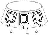
도 4b는 본 발명의 일 실시예에 따른 복수의 송신 코일부를 포함하는 무선 전력 송신 장치의 일부분을 나타낸 사시도이다.4B is a perspective view illustrating a portion of a wireless power transmission apparatus including a plurality of transmission coil units according to an embodiment of the present invention.
도 4b를 참조하면, 무선 전력 송신 장치(200)는 원뿔형의 형태를 가지며 복수의 송신 코일부들(241, 242, 243)을 포함할 수 있다.Referring to FIG. 4B, the wireless
도 4b에서 제1 내지 제3 송신 코일부들(241, 242, 243)을 확인할 수 있고, 추가적으로 채용된 송신 코일부들은 도시를 생략하였다.In FIG. 4B, the first to third
무선 전력 수신 장치(100)는 무선 전력 송신 장치(200)의 설계 형태에 따라 이물질을 배제하고 충전 영역에 배치될 수 있다.
The wireless
이하, 복수의 송신 코일부들(241, 242, 243, 244, ...)을 채용하는 무선 전력 송신 장치에 있어 복수의 송신 코일부들(241, 242, 243, 244, ...) 중 효율적인 송신 코일부를 선택하는 방법을 설명한다.
In a radio power transmission apparatus employing a plurality of
도 5는 본 발명의 일 실시예에 따른 무선 전력 송신 방법을 설명하는 간략한 흐름도이다.5 is a simplified flow diagram illustrating a wireless power transmission method in accordance with an embodiment of the present invention.
도 5를 참조하면, 본 실시예에 무선 전력 송신 방법은, 제어부(도 2의 220)가 복수의 송신 코일부들(도 2의 241, 242, 243, 244, ...)이 순차적으로 대기동작하도록 전력 공급부(도 2의 230)를 제어하는 것으로 시작된다(S510).Referring to FIG. 5, in the wireless power transmission method according to the present embodiment, a plurality of transmission coil portions (241, 242, 243, 244, ...) And starts to control the power supply (230 in FIG. 2) to operate (S510).
제어부(도 2의 220)는 대기동작 중에 무선 전력 수신 장치(도 1의 100)로부터 응답신호가 수신되었는지 여부를 판단 할 수 있다(S520).The
상기 응답신호는 무선 전력 수신 장치(도 1의 100)로부터의 애드버타이즈먼트 패킷(advertisement packet)일 수 있다.The response signal may be an advertisement packet from the wireless power receiving apparatus 100 (FIG. 1).
응답신호가 수신되었는지 여부를 판단하기 위해, 제어부(도 2의 220)는 상기 애드버타이즈먼트 패킷에 포함된 RSSI(Received Signal Strength Indication)를 이용하여 상기 응답신호의 수신 여부를 판단할 수 있다.In order to determine whether or not a response signal has been received, the
제어부(도 2의 220)는 통신부(도 2의 210)에서 수신한 상기 애드버타이즈먼트 패킷에 포함된 RSSI(Received Signal Strength Indication)가 기준 신호 레벨 이상이면 상기 응답신호가 수신되었다고 판단할 수 있다.2) can determine that the response signal has been received if RSSI (Received Signal Strength Indication) included in the advertisement packet received from the communication unit 210 (210 in FIG. 2) is equal to or higher than a reference signal level .
반대로, 제어부(도 2의 220)는 통신부(도 2의 210)에서 수신한 애드버타이즈먼트 패킷의 RSSI가 기준 신호 레벨 이하이면 상기 응답신호가 수신되지 않았다고 판단하고 상기 대기동작을 계속 수행하도록 제어할 수 있다.
2) determines that the response signal is not received when the RSSI of the advertisement packet received by the communication unit 210 (210 in FIG. 2) is lower than the reference signal level, and controls the control unit can do.
응답신호가 수신되었다고 판단한 경우, 제어부(도 2의 220)는 전력 전송 효율을 비교하여 전력 송신을 위한 송신 코일부를 선택할 수 있다(S530).If it is determined that a response signal has been received, the
구체적으로, 통신부(도 2의 210)는 응답신호의 수신 이후에 무선 전력 수신 장치(도 1의 100)로부터 전압 정보, 전류 정보 등이 포함된 동작 특성 신호를 수신하여 제어부(도 2의 220)로 전달할 수 있다. 또한, 제어부(도 2의 220)는 응답신호가 수신된 시점에 대기동작 중인 송신 코일부의 동작 특성 신호에 포함된 전압정보를 획득할 수 있다.2) 210 receives an operation characteristic signal including voltage information, current information, and the like from the wireless power receiving apparatus (100 of FIG. 1) after receiving the response signal, . In addition, the controller (220 in FIG. 2) can acquire the voltage information included in the operation characteristic signal of the transmission coil part in standby operation at the time of reception of the response signal.
이후, 제어부(도 2의 220)는 상기 응답신호가 수신된 시점에 대기동작 중인 송신 코일부에 인접한 송신 코일부의 동작 특성 신호를 획득할 수 있다.Then, the
제어부(도 2의 220)는 상기 인접한 송신 코일부의 동작 특성 신호에 포함된 전압정보와 응답신호가 수신된 시점에 대기동작 중인 송신 코일부의 동작 특성 신호에 포함된 전압정보를 비교하여 전력 전송 효율이 높은 송신 코일부를 선택할 수 있다.The
이후, 제어부(도 2의 220)는 상기 선택한 송신 코일부를 통하여 무선 전력 수신 장치(도 1의 100)로 전력을 송신할 수 있다(S540).Then, the controller (220 in FIG. 2) can transmit the power to the wireless power receiving apparatus (100 in FIG. 1) through the selected transmitting coil part (S540).
이에 따라, 복수의 송신 코일부들(도 2의 241, 242, 243, 244, ...) 중 전송 효율이 높은 송신 코일부를 통하여 전력이 전송될 수 있으므로, 효율적인 전력 전송을 할 수 있다.
Accordingly, since power can be transmitted through a transmission coil part having a high transmission efficiency among a plurality of transmission coil parts (241, 242, 243, 244, ... in FIG. 2), efficient power transmission can be performed.
도 6은 도 5에 나타낸 본 발명의 일 실시예에 따른 무선 전력 송신 방법의 대기 동작 단계(S510)의 실시예를 설명하는 흐름도이다.FIG. 6 is a flow chart illustrating an embodiment of a standby operation step (S510) of the wireless power transmission method according to an embodiment of the present invention shown in FIG.
도 6을 참조하면, 제어부(도 2의 220)은 대기동작하는 송신 코일부의 변경 여부를 판단하기 위해 현재 대기동작 중인 송신 코일부의 대기동작 중인 시간(t)을 대기시간(twait-)과 비교할 수 있다(S511).6, the control unit (Fig. 220 in Fig. 2) is waiting time pending operation of the transmission coil are currently standby operation (t) to determine whether the change in the transmit coil for standby operation (twait-) (S511).
비교에 따라, 제어부(도 2의 220)는 현재 대기동작 중인 송신 코일부의 대기동작 중인 시간(t)이 대기시간(twait)을 초과한 경우 상기 대기동작하는 송신 코일부를 변경하여(S512), 상기 복수의 송신 코일부들 각각이 상기 대기시간 동안 순차적으로 대기동작하도록 전력 공급부(도 2의 230)을 제어할 수 있다.According to the comparison, the
다음으로, 전력 공급부(도 2의 230)는 제어부(도 2의 220)의 제어에 따라 사전에 설정된 제1 주기를 갖는 숏 비컨을 전송하여(S513) 무선 전력 수신 장치(도 1의 100)의 근접을 인지할 수 있다.Next, the power supply unit (230 in FIG. 2) transmits a short beacon having a first period set in advance according to the control of the controller (220 in FIG. 2) (S513) I can recognize the proximity.
무선 전력 수신 장치(도 1의 100)가 근접하였는지는 전력 공급부(도 2의 230)가 연결한 송신 코일부의 임피던스(impedance) 변화를 검출하여 기준 이상으로 임피던스가 변한 경우 무선 전력 수신 장치(도 1의 100)가 근접한 것으로 인지할 수 있다(S514).If the impedance of the transmission coil part connected to the power supply part (230 in FIG. 2) is detected by detecting the impedance of the wireless power receiving device (100 in FIG. 1) 100) is close to the current position (S514).
또한, 전력 공급부(도 2의 230)는 제어부(도 2의 220)의 제어에 따라 상기 제1 주기와 상이한 제2 주기를 가지는 롱 비컨을 전송하여(S515), 인접한 무선 전력 수신 장치(100)의 블루투스 회로를 웨이크 업 시킬 수 있다(S516). 상기 롱 비컨 신호는 상기 S514 단계에서 판단한 결과, 기준 이상으로 임피던스가 변화한 경우에도 전송될 수 있다. 즉, 롱 비컨 신호는 제2 주기가 도래한 경우 또는 숏 비컨 신호의 전송 후 송신 코일부의 임피던스 변화가 발생된 경우에, 제어부(도 2의 220)에 따라 전력 공급부(도 2의 230)에 의해 전송될 수 있다.In addition, the
이후, 통신부(도 2의 210)는 제어부(도 2의 220)의 제어에 따라 블루투스 회로가 웨이크 업된 무선 전력 수신 장치(도 1의 100)에 연결 요청 신호를 전송할 수 있다(S517).Then, the
다음으로, 상기 서술한 바와 같이, 제어부(도 2의 220)는 연결 요청 신호의 전송 후에 무선 전력 수신 장치(도 1의 100)로부터 응답신호가 수신되었는지 여부를 판단 할 수 있다(S520).
Next, as described above, the
이상에서 본 발명이 구체적인 구성요소 등과 같은 특정 사항들과 한정된 실시예 및 도면에 의해 설명되었으나, 이는 본 발명의 보다 전반적인 이해를 돕기 위해서 제공된 것일 뿐, 본 발명이 상기 실시예들에 한정되는 것은 아니며, 본 발명이 속하는 기술분야에서 통상적인 지식을 가진 자라면 이러한 기재로부터 다양한 수정 및 변형을 꾀할 수 있다.While the present invention has been particularly shown and described with reference to exemplary embodiments thereof, it is to be understood that the invention is not limited to the disclosed exemplary embodiments, but, on the contrary, Those skilled in the art will appreciate that various modifications, additions and substitutions are possible, without departing from the scope and spirit of the invention as disclosed in the accompanying claims.
따라서, 본 발명의 사상은 상기 설명된 실시예에 국한되어 정해져서는 아니 되며, 후술하는 특허청구범위뿐만 아니라 이 특허청구범위와 균등하게 또는 등가적으로 변형된 모든 것들은 본 발명의 사상의 범주에 속한다고 할 것이다.
Therefore, the spirit of the present invention should not be construed as being limited to the above-described embodiments, and all of the equivalents or equivalents of the claims, as well as the following claims, I will say.
100: 무선 전력 수신 장치
200: 무선 전력 송신 장치
210: 통신부
220: 제어부
230: 전력 공급부
241, 242, 243, 244: 제1 내지 제4 송신 코일부100: Wireless power receiving device
200: Wireless power transmitting device
210:
220:
230: Power supply
241, 242, 243, and 244: first to fourth transmission coil parts
Claims (16)
Translated fromKorean상기 무선 전력 수신 장치와 통신하는 통신부;
상기 복수의 송신 코일부들과 선택적으로 연결되어 전력을 공급하는 전력 공급부; 및
상기 복수의 송신 코일부들을 순차적으로 대기동작하도록 상기 전력 공급부를 제어하고, 상기 통신부로 상기 무선 전력 수신 장치의 응답신호가 수신된 시점에 대기동작 중인 송신 코일부와 인접한 송신 코일부의 전력 전송 효율을 비교하여 선택한 송신 코일부를 이용하여 전력을 전송하도록 전력 공급부를 제어하는 제어부;
를 포함하는 무선 전력 송신 장치.
A plurality of transmitting coil sections arranged to transmit power wirelessly to a wireless power receiving apparatus, each of the transmitting coil sections being arranged to form a magnetic flux from a different position to the wireless power receiving apparatus;
A communication unit for communicating with the wireless power receiving apparatus;
A power supply unit selectively connected to the plurality of transmission coil units to supply power; And
And controls the power supply unit so as to sequentially operate the plurality of transmission coil units, and when the response signal of the wireless power reception apparatus is received by the communication unit, a power transmission efficiency And controls the power supply unit to transmit power using the selected transmission coil part;
And a wireless power transmitter.
대기시간이 초과된 경우 상기 대기동작하는 송신 코일부를 변경하여 상기 복수의 송신 코일부들 각각이 상기 대기시간 동안 순차적으로 상기 대기동작하도록 전력 공급부를 제어하는 무선 전력 송신 장치.
The apparatus of claim 1, wherein the control unit
And controls the power supply unit such that each of the plurality of transmission coil units performs the standby operation sequentially during the standby time by changing the transmission coil part that operates in the standby mode when the standby time is exceeded.
상기 복수의 송신 코일부들 중 대기동작중인 송신 코일부가 숏 비컨(short beacon)을 전송하도록 상기 전력 공급부를 제어하여 무선 전력 수신 장치의 근접을 인지하고, 상기 복수의 송신 코일부들 중 대기동작 중인 송신 코일부가 롱 비컨을(long beacon)을 전송하도록 상기 전력 공급부를 제어하여 무선 전력 수신 장치의 블루투스 회로를 웨이크 업(wake up)시키는 무선 전력 송신 장치.
The apparatus of claim 1, wherein the control unit
Wherein the control unit controls the power supply unit so as to transmit a short beacon in a waiting coil of the plurality of transmission coil units to recognize proximity of the wireless power reception apparatus, And controls the power supply unit so that the transmission coil unit transmits a long beacon so as to wake up the Bluetooth circuit of the wireless power receiving apparatus.
상기 무선 전력 수신 장치로부터의 애드버타이즈먼트 패킷(advertisement packet)이고,
상기 제어부는 상기 애드버타이즈먼트 패킷에 포함된 RSSI(Received Signal Strength Indication)를 이용하여 상기 응답신호의 수신 여부를 판단하는 무선 전력 송신 장치.
The method of claim 1,
An advertisement packet from the wireless power receiving apparatus,
Wherein the control unit determines whether to receive the response signal using RSSI (Received Signal Strength Indication) included in the advertisement packet.
상기 무선 전력 수신 장치로부터 수신한 동작특성신호에 포함된 전압정보를 이용하여 전력 전송 효율을 비교하는 무선 전력 송신 장치.
The apparatus of claim 1, wherein the control unit
And compares the power transmission efficiency using the voltage information included in the operation characteristic signal received from the wireless power receiving apparatus.
상기 통신부는 상기 무선 전력 수신 장치의 블루투스 회로와 BLE(Bluetooth Low Energy) 통신하는 무선 전력 송신 장치.
The method according to claim 1,
Wherein the communication unit is BLE (Bluetooth Low Energy) communication with the Bluetooth circuit of the wireless power receiving apparatus.
(b) 무선 전력 수신 장치의 응답신호를 수신하는 단계;
(c) 상기 응답신호가 수신된 시점에 대기동작 중인 송신 코일부와 인접한 송신 코일부의 전력 전송 효율을 비교하여 송신 코일부를 선택하는 단계; 및
(d) 상기 선택된 송신 코일부를 이용하여 전력을 전송하는 단계를 포함하는 무선 전력 송신 방법.
(a) recognizing the proximity of the wireless power receiving apparatus by transmitting a short beacon, transmitting a long beacon to wake up the Bluetooth circuit of the wireless power receiving apparatus, Controlling the power supply unit so that the coil units sequentially operate in standby;
(b) receiving a response signal of the wireless power receiving apparatus;
(c) comparing a power transmission efficiency of a transmitting coil part in a waiting operation and a neighboring transmitting coil part at the time of reception of the response signal to select a transmitting coil part; And
(d) transmitting power using the selected transmit coil portion.
대기시간이 초과된 경우 상기 대기동작하는 송신 코일부를 변경하여 상기 복수의 송신 코일부들 각각이 상기 대기시간 동안 순차적으로 상기 대기동작하도록 전력 공급부를 제어하는 무선 전력 송신 방법.
10. The method of claim 9, wherein step (a)
And changes the transmitting coil part to operate in standby mode if the waiting time is exceeded, so that each of the plurality of transmitting coil parts controls the power supply part so as to sequentially perform the waiting operation during the standby time.
상기 무선 전력 수신 장치로부터의 애드버타이즈먼트 패킷(advertisement packet)을 수신하는 단계; 및
상기 애드버타이즈먼트 패킷에 포함된 RSSI(Received Signal Strength Indication)를 이용하여 상기 응답신호의 수신 여부를 판단하는 단계; 를 포함하는 무선 전력 송신 방법.
10. The method of claim 9, wherein step (b)
Receiving an advertisement packet from the wireless power receiving apparatus; And
Determining whether the response signal is received using RSSI (Received Signal Strength Indication) included in the advertisement packet; / RTI >
상기 무선 전력 수신 장치로부터 수신한 동작특성신호에 포함된 전압정보를 이용하여 전력 전송 효율을 비교하는 단계를 더 포함하는 무선 전력 송신 방법.
10. The method of claim 9, wherein step (c)
And comparing the power transmission efficiency using the voltage information included in the operating characteristic signal received from the wireless power receiving apparatus.
상기 무선 전력 송신 장치는 원뿔형 또는 원통형 형태를 가지고,
상기 복수의 송신 코일부들은 원뿔형 또는 원통형의 축을 둘러싸도록 배치되는 무선 전력 송신 장치.The method according to claim 1,
The wireless power transmission device has a conical or cylindrical shape,
Wherein the plurality of transmitting coil sections are arranged to surround a conical or cylindrical axis.
Priority Applications (1)
| Application Number | Priority Date | Filing Date | Title |
|---|---|---|---|
| KR1020140115661AKR101994739B1 (en) | 2014-09-01 | 2014-09-01 | Wireless power transmitting apparatus and wireless power transmitting methid |
Applications Claiming Priority (1)
| Application Number | Priority Date | Filing Date | Title |
|---|---|---|---|
| KR1020140115661AKR101994739B1 (en) | 2014-09-01 | 2014-09-01 | Wireless power transmitting apparatus and wireless power transmitting methid |
Publications (2)
| Publication Number | Publication Date |
|---|---|
| KR20160026556A KR20160026556A (en) | 2016-03-09 |
| KR101994739B1true KR101994739B1 (en) | 2019-07-01 |
Family
ID=55536922
Family Applications (1)
| Application Number | Title | Priority Date | Filing Date |
|---|---|---|---|
| KR1020140115661AActiveKR101994739B1 (en) | 2014-09-01 | 2014-09-01 | Wireless power transmitting apparatus and wireless power transmitting methid |
Country Status (1)
| Country | Link |
|---|---|
| KR (1) | KR101994739B1 (en) |
Cited By (1)
| Publication number | Priority date | Publication date | Assignee | Title |
|---|---|---|---|---|
| US11949253B2 (en) | 2021-01-29 | 2024-04-02 | Samsung Electronics Co., Ltd | Electronic device for transmitting wireless power and method for wireless charging thereof |
Families Citing this family (6)
| Publication number | Priority date | Publication date | Assignee | Title |
|---|---|---|---|---|
| KR102601601B1 (en)* | 2016-04-19 | 2023-11-13 | 삼성전자주식회사 | Wireless Power Transceiver using phase and amplitude control algorithm and wireless power receiver |
| KR102421069B1 (en) | 2017-04-19 | 2022-07-14 | 엘지이노텍 주식회사 | Wireless Power Transmitter for Wireless Charging |
| KR102540921B1 (en)* | 2018-06-29 | 2023-06-07 | 현대자동차주식회사 | Wireless charger for a vehicle and operating method thereof |
| EP3863148A4 (en) | 2018-10-04 | 2022-06-22 | LG Electronics Inc. | WIRELESS CURRENT TRANSMITTER |
| KR102569215B1 (en)* | 2018-10-04 | 2023-08-21 | 엘지전자 주식회사 | Wireless power transfer appratus |
| KR102206468B1 (en)* | 2019-08-06 | 2021-01-21 | 엘지전자 주식회사 | Wireless power transfer apparatus and method thereof |
Citations (2)
| Publication number | Priority date | Publication date | Assignee | Title |
|---|---|---|---|---|
| JP2011130569A (en)* | 2009-12-17 | 2011-06-30 | Toko Inc | Noncontact power transfer device |
| JP2014103802A (en)* | 2012-11-21 | 2014-06-05 | Toyota Motor Corp | Transmission device and power transmission system |
Family Cites Families (4)
| Publication number | Priority date | Publication date | Assignee | Title |
|---|---|---|---|---|
| US8338990B2 (en)* | 2008-03-13 | 2012-12-25 | Access Business Group International Llc | Inductive power supply system with multiple coil primary |
| US20090284369A1 (en) | 2008-05-13 | 2009-11-19 | Qualcomm Incorporated | Transmit power control for a wireless charging system |
| KR101309840B1 (en)* | 2009-12-17 | 2013-09-23 | 한국전자통신연구원 | Apparatus and method for supplying power in a wireless sensor network |
| KR20130006326A (en)* | 2011-07-07 | 2013-01-16 | 삼성전자주식회사 | Wireless power transmission and charging system, power control and communication method of wireless power transmission and charging system |
- 2014
- 2014-09-01KRKR1020140115661Apatent/KR101994739B1/enactiveActive
Patent Citations (2)
| Publication number | Priority date | Publication date | Assignee | Title |
|---|---|---|---|---|
| JP2011130569A (en)* | 2009-12-17 | 2011-06-30 | Toko Inc | Noncontact power transfer device |
| JP2014103802A (en)* | 2012-11-21 | 2014-06-05 | Toyota Motor Corp | Transmission device and power transmission system |
Cited By (1)
| Publication number | Priority date | Publication date | Assignee | Title |
|---|---|---|---|---|
| US11949253B2 (en) | 2021-01-29 | 2024-04-02 | Samsung Electronics Co., Ltd | Electronic device for transmitting wireless power and method for wireless charging thereof |
Also Published As
| Publication number | Publication date |
|---|---|
| KR20160026556A (en) | 2016-03-09 |
Similar Documents
| Publication | Publication Date | Title |
|---|---|---|
| KR101994739B1 (en) | Wireless power transmitting apparatus and wireless power transmitting methid | |
| KR102680568B1 (en) | Method and apparatus of adjusting coil location in wireless power transfer system | |
| KR102340996B1 (en) | Apparatus and method for power transmitting wirelessly | |
| US9769869B2 (en) | Non-contact type power supply apparatus and non-contact type power supply method | |
| CN107078522B (en) | System and method for preventing wireless charging cross-connects | |
| KR101498766B1 (en) | Selecting method of sensoring modules commonly used by Near Field Communication and Wireless charging, and its selective electric circuit | |
| JP6643041B2 (en) | Power transmission equipment | |
| CN103348563A (en) | Power transmitting apparatus, power receiving apparatus, and power transmitting method | |
| JP5587165B2 (en) | Non-contact power transmission system and power receiving antenna | |
| EP3404796A1 (en) | Wireless power control method and device therefor | |
| KR102154306B1 (en) | Wireless power transmission device which enables to simultaneously charge | |
| TW201415749A (en) | Wireless power supply system for supporting multi remote devices | |
| KR101476103B1 (en) | Smart phone for wireless-charging wearable device and method for transmitting wireless power of the same | |
| WO2015019560A1 (en) | Power receiving apparatus | |
| KR101471806B1 (en) | Multi-adaptive switch apparatus of resonant wireless charging receiver and method thereof | |
| KR20140134688A (en) | Power delivery device and power delivery/power receiving system | |
| US20200076233A1 (en) | Mouse pad comprising wireless power transmission apparatus and mouse | |
| EP2882063A1 (en) | Non-contact type power supplying apparatus and non-contact type power supplying method | |
| JP2017028770A (en) | Wireless power supply system | |
| KR101228105B1 (en) | Wireless charging system and the control method | |
| KR20130121466A (en) | Apparatus and method for transmitting wireless energy in energy transmission system | |
| JP2014179746A (en) | Portable radio equipment and contactless charging system using the same | |
| KR20150057951A (en) | Non-contact type power supplying apparatus and non-contact type power supplying method | |
| JP2014217116A (en) | Electronic apparatus, electronic apparatus power transmission system and power reception control method | |
| JP5817483B2 (en) | Mobile terminal and control method thereof |
Legal Events
| Date | Code | Title | Description |
|---|---|---|---|
| PA0109 | Patent application | Patent event code:PA01091R01D Comment text:Patent Application Patent event date:20140901 | |
| PG1501 | Laying open of application | ||
| A201 | Request for examination | ||
| PA0201 | Request for examination | Patent event code:PA02012R01D Patent event date:20171027 Comment text:Request for Examination of Application Patent event code:PA02011R01I Patent event date:20140901 Comment text:Patent Application | |
| E902 | Notification of reason for refusal | ||
| PE0902 | Notice of grounds for rejection | Comment text:Notification of reason for refusal Patent event date:20181019 Patent event code:PE09021S01D | |
| E701 | Decision to grant or registration of patent right | ||
| PE0701 | Decision of registration | Patent event code:PE07011S01D Comment text:Decision to Grant Registration Patent event date:20190424 | |
| GRNT | Written decision to grant | ||
| PR0701 | Registration of establishment | Comment text:Registration of Establishment Patent event date:20190625 Patent event code:PR07011E01D | |
| PR1002 | Payment of registration fee | Payment date:20190626 End annual number:3 Start annual number:1 | |
| PG1601 | Publication of registration | ||
| PR1001 | Payment of annual fee | Payment date:20220329 Start annual number:4 End annual number:4 | |
| PR1001 | Payment of annual fee | Payment date:20230320 Start annual number:5 End annual number:5 | |
| PR1001 | Payment of annual fee | Payment date:20240326 Start annual number:6 End annual number:6 | |
| PR1001 | Payment of annual fee | Payment date:20250318 Start annual number:7 End annual number:7 |