KR101993815B1 - Decoupling instrument shaft roll and end effector actuation in a surgical instrument - Google Patents
Decoupling instrument shaft roll and end effector actuation in a surgical instrumentDownload PDFInfo
- Publication number
- KR101993815B1 KR101993815B1KR1020187024608AKR20187024608AKR101993815B1KR 101993815 B1KR101993815 B1KR 101993815B1KR 1020187024608 AKR1020187024608 AKR 1020187024608AKR 20187024608 AKR20187024608 AKR 20187024608AKR 101993815 B1KR101993815 B1KR 101993815B1
- Authority
- KR
- South Korea
- Prior art keywords
- torque
- main shaft
- drive
- shaft
- rotation
- Prior art date
- Legal status (The legal status is an assumption and is not a legal conclusion. Google has not performed a legal analysis and makes no representation as to the accuracy of the status listed.)
- Active
Links
Images


Classifications
- A—HUMAN NECESSITIES
- A61—MEDICAL OR VETERINARY SCIENCE; HYGIENE
- A61B—DIAGNOSIS; SURGERY; IDENTIFICATION
- A61B34/00—Computer-aided surgery; Manipulators or robots specially adapted for use in surgery
- A61B34/70—Manipulators specially adapted for use in surgery
- A—HUMAN NECESSITIES
- A61—MEDICAL OR VETERINARY SCIENCE; HYGIENE
- A61B—DIAGNOSIS; SURGERY; IDENTIFICATION
- A61B17/00—Surgical instruments, devices or methods
- A—HUMAN NECESSITIES
- A61—MEDICAL OR VETERINARY SCIENCE; HYGIENE
- A61B—DIAGNOSIS; SURGERY; IDENTIFICATION
- A61B17/00—Surgical instruments, devices or methods
- A61B17/00234—Surgical instruments, devices or methods for minimally invasive surgery
- A—HUMAN NECESSITIES
- A61—MEDICAL OR VETERINARY SCIENCE; HYGIENE
- A61B—DIAGNOSIS; SURGERY; IDENTIFICATION
- A61B17/00—Surgical instruments, devices or methods
- A61B17/28—Surgical forceps
- A61B17/29—Forceps for use in minimally invasive surgery
- A—HUMAN NECESSITIES
- A61—MEDICAL OR VETERINARY SCIENCE; HYGIENE
- A61B—DIAGNOSIS; SURGERY; IDENTIFICATION
- A61B34/00—Computer-aided surgery; Manipulators or robots specially adapted for use in surgery
- A61B34/30—Surgical robots
- A—HUMAN NECESSITIES
- A61—MEDICAL OR VETERINARY SCIENCE; HYGIENE
- A61B—DIAGNOSIS; SURGERY; IDENTIFICATION
- A61B34/00—Computer-aided surgery; Manipulators or robots specially adapted for use in surgery
- A61B34/70—Manipulators specially adapted for use in surgery
- A61B34/71—Manipulators operated by drive cable mechanisms
- A—HUMAN NECESSITIES
- A61—MEDICAL OR VETERINARY SCIENCE; HYGIENE
- A61B—DIAGNOSIS; SURGERY; IDENTIFICATION
- A61B90/00—Instruments, implements or accessories specially adapted for surgery or diagnosis and not covered by any of the groups A61B1/00 - A61B50/00, e.g. for luxation treatment or for protecting wound edges
- A61B90/03—Automatic limiting or abutting means, e.g. for safety
- A—HUMAN NECESSITIES
- A61—MEDICAL OR VETERINARY SCIENCE; HYGIENE
- A61B—DIAGNOSIS; SURGERY; IDENTIFICATION
- A61B17/00—Surgical instruments, devices or methods
- A61B17/28—Surgical forceps
- A—HUMAN NECESSITIES
- A61—MEDICAL OR VETERINARY SCIENCE; HYGIENE
- A61B—DIAGNOSIS; SURGERY; IDENTIFICATION
- A61B17/00—Surgical instruments, devices or methods
- A61B2017/00017—Electrical control of surgical instruments
- A—HUMAN NECESSITIES
- A61—MEDICAL OR VETERINARY SCIENCE; HYGIENE
- A61B—DIAGNOSIS; SURGERY; IDENTIFICATION
- A61B17/00—Surgical instruments, devices or methods
- A61B2017/00367—Details of actuation of instruments, e.g. relations between pushing buttons, or the like, and activation of the tool, working tip, or the like
- A61B2017/00398—Details of actuation of instruments, e.g. relations between pushing buttons, or the like, and activation of the tool, working tip, or the like using powered actuators, e.g. stepper motors, solenoids
- A—HUMAN NECESSITIES
- A61—MEDICAL OR VETERINARY SCIENCE; HYGIENE
- A61B—DIAGNOSIS; SURGERY; IDENTIFICATION
- A61B17/00—Surgical instruments, devices or methods
- A61B2017/00477—Coupling
- A—HUMAN NECESSITIES
- A61—MEDICAL OR VETERINARY SCIENCE; HYGIENE
- A61B—DIAGNOSIS; SURGERY; IDENTIFICATION
- A61B17/00—Surgical instruments, devices or methods
- A61B17/28—Surgical forceps
- A61B17/29—Forceps for use in minimally invasive surgery
- A61B2017/2901—Details of shaft
- A—HUMAN NECESSITIES
- A61—MEDICAL OR VETERINARY SCIENCE; HYGIENE
- A61B—DIAGNOSIS; SURGERY; IDENTIFICATION
- A61B17/00—Surgical instruments, devices or methods
- A61B17/28—Surgical forceps
- A61B17/29—Forceps for use in minimally invasive surgery
- A61B2017/2901—Details of shaft
- A61B2017/2902—Details of shaft characterized by features of the actuating rod
- A61B2017/2903—Details of shaft characterized by features of the actuating rod transferring rotary motion
- A—HUMAN NECESSITIES
- A61—MEDICAL OR VETERINARY SCIENCE; HYGIENE
- A61B—DIAGNOSIS; SURGERY; IDENTIFICATION
- A61B17/00—Surgical instruments, devices or methods
- A61B17/28—Surgical forceps
- A61B17/29—Forceps for use in minimally invasive surgery
- A61B2017/2926—Details of heads or jaws
- A61B2017/2927—Details of heads or jaws the angular position of the head being adjustable with respect to the shaft
- A61B2017/2929—Details of heads or jaws the angular position of the head being adjustable with respect to the shaft with a head rotatable about the longitudinal axis of the shaft
- A61B2017/293—Details of heads or jaws the angular position of the head being adjustable with respect to the shaft with a head rotatable about the longitudinal axis of the shaft with means preventing relative rotation between the shaft and the actuating rod
- A—HUMAN NECESSITIES
- A61—MEDICAL OR VETERINARY SCIENCE; HYGIENE
- A61B—DIAGNOSIS; SURGERY; IDENTIFICATION
- A61B17/00—Surgical instruments, devices or methods
- A61B17/28—Surgical forceps
- A61B17/29—Forceps for use in minimally invasive surgery
- A61B2017/2926—Details of heads or jaws
- A61B2017/2932—Transmission of forces to jaw members
- A61B2017/2933—Transmission of forces to jaw members camming or guiding means
- A61B2017/2936—Pins in guiding slots
- A—HUMAN NECESSITIES
- A61—MEDICAL OR VETERINARY SCIENCE; HYGIENE
- A61B—DIAGNOSIS; SURGERY; IDENTIFICATION
- A61B17/00—Surgical instruments, devices or methods
- A61B17/28—Surgical forceps
- A61B17/29—Forceps for use in minimally invasive surgery
- A61B2017/2926—Details of heads or jaws
- A61B2017/2932—Transmission of forces to jaw members
- A61B2017/2938—Independently actuatable jaw members, e.g. two actuating rods
- A—HUMAN NECESSITIES
- A61—MEDICAL OR VETERINARY SCIENCE; HYGIENE
- A61B—DIAGNOSIS; SURGERY; IDENTIFICATION
- A61B17/00—Surgical instruments, devices or methods
- A61B17/28—Surgical forceps
- A61B17/29—Forceps for use in minimally invasive surgery
- A61B2017/2926—Details of heads or jaws
- A61B2017/2932—Transmission of forces to jaw members
- A61B2017/2943—Toothed members, e.g. rack and pinion
- A—HUMAN NECESSITIES
- A61—MEDICAL OR VETERINARY SCIENCE; HYGIENE
- A61B—DIAGNOSIS; SURGERY; IDENTIFICATION
- A61B34/00—Computer-aided surgery; Manipulators or robots specially adapted for use in surgery
- A61B34/20—Surgical navigation systems; Devices for tracking or guiding surgical instruments, e.g. for frameless stereotaxis
- A61B2034/2046—Tracking techniques
- A61B2034/2059—Mechanical position encoders
- A—HUMAN NECESSITIES
- A61—MEDICAL OR VETERINARY SCIENCE; HYGIENE
- A61B—DIAGNOSIS; SURGERY; IDENTIFICATION
- A61B34/00—Computer-aided surgery; Manipulators or robots specially adapted for use in surgery
- A61B34/30—Surgical robots
- A61B2034/301—Surgical robots for introducing or steering flexible instruments inserted into the body, e.g. catheters or endoscopes
- A—HUMAN NECESSITIES
- A61—MEDICAL OR VETERINARY SCIENCE; HYGIENE
- A61B—DIAGNOSIS; SURGERY; IDENTIFICATION
- A61B34/00—Computer-aided surgery; Manipulators or robots specially adapted for use in surgery
- A61B34/30—Surgical robots
- A61B2034/302—Surgical robots specifically adapted for manipulations within body cavities, e.g. within abdominal or thoracic cavities
- A—HUMAN NECESSITIES
- A61—MEDICAL OR VETERINARY SCIENCE; HYGIENE
- A61B—DIAGNOSIS; SURGERY; IDENTIFICATION
- A61B34/00—Computer-aided surgery; Manipulators or robots specially adapted for use in surgery
- A61B34/30—Surgical robots
- A61B2034/303—Surgical robots specifically adapted for manipulations within body lumens, e.g. within lumen of gut, spine, or blood vessels
- A—HUMAN NECESSITIES
- A61—MEDICAL OR VETERINARY SCIENCE; HYGIENE
- A61B—DIAGNOSIS; SURGERY; IDENTIFICATION
- A61B34/00—Computer-aided surgery; Manipulators or robots specially adapted for use in surgery
- A61B34/70—Manipulators specially adapted for use in surgery
- A61B34/71—Manipulators operated by drive cable mechanisms
- A61B2034/715—Cable tensioning mechanisms for removing slack
- A—HUMAN NECESSITIES
- A61—MEDICAL OR VETERINARY SCIENCE; HYGIENE
- A61B—DIAGNOSIS; SURGERY; IDENTIFICATION
- A61B90/00—Instruments, implements or accessories specially adapted for surgery or diagnosis and not covered by any of the groups A61B1/00 - A61B50/00, e.g. for luxation treatment or for protecting wound edges
- A61B90/03—Automatic limiting or abutting means, e.g. for safety
- A61B2090/031—Automatic limiting or abutting means, e.g. for safety torque limiting
- A—HUMAN NECESSITIES
- A61—MEDICAL OR VETERINARY SCIENCE; HYGIENE
- A61B—DIAGNOSIS; SURGERY; IDENTIFICATION
- A61B90/00—Instruments, implements or accessories specially adapted for surgery or diagnosis and not covered by any of the groups A61B1/00 - A61B50/00, e.g. for luxation treatment or for protecting wound edges
- A61B90/06—Measuring instruments not otherwise provided for
- A61B2090/067—Measuring instruments not otherwise provided for for measuring angles
- A—HUMAN NECESSITIES
- A61—MEDICAL OR VETERINARY SCIENCE; HYGIENE
- A61B—DIAGNOSIS; SURGERY; IDENTIFICATION
- A61B34/00—Computer-aided surgery; Manipulators or robots specially adapted for use in surgery
- A61B34/30—Surgical robots
- A61B34/32—Surgical robots operating autonomously
- A—HUMAN NECESSITIES
- A61—MEDICAL OR VETERINARY SCIENCE; HYGIENE
- A61B—DIAGNOSIS; SURGERY; IDENTIFICATION
- A61B34/00—Computer-aided surgery; Manipulators or robots specially adapted for use in surgery
- A61B34/30—Surgical robots
- A61B34/37—Leader-follower robots
Landscapes
- Health & Medical Sciences (AREA)
- Life Sciences & Earth Sciences (AREA)
- Surgery (AREA)
- Engineering & Computer Science (AREA)
- Animal Behavior & Ethology (AREA)
- Veterinary Medicine (AREA)
- Biomedical Technology (AREA)
- Heart & Thoracic Surgery (AREA)
- Medical Informatics (AREA)
- Molecular Biology (AREA)
- Nuclear Medicine, Radiotherapy & Molecular Imaging (AREA)
- General Health & Medical Sciences (AREA)
- Public Health (AREA)
- Robotics (AREA)
- Ophthalmology & Optometry (AREA)
- Oral & Maxillofacial Surgery (AREA)
- Pathology (AREA)
- Manipulator (AREA)
- Surgical Instruments (AREA)
- Endoscopes (AREA)
- Transmission Devices (AREA)
Abstract
Translated fromKorean
Description
Translated fromKorean본 출원은 2010년 11월 15일자 제출된 미국 가 출원 제61/413,885호, 발명의 명칭 "독립적으로 회전하는 부재에 원격 작동장치에 의해 적용된 토크를 수동적으로 해제하는 방법"(대리인 서류 번호 No. ISRG 02930PROV/US) 및 2011년 5월 31일자 제출된 미국 가 출원 제61/491,789호, 발명의 명칭 "수술 기구에서 기구 샤프트 감김과 단부 작동기 작동의 해제"(대리인 서류 번호 No. ISRG 03310/US)의 우선권을 주장하며, 이들의 전체 개시내용은 본원에 참고자료로 포함된다.The present application is related to U.S. Provisional Application No. 61 / 413,885 filed on November 15, 2010, entitled " Method for Manually Releasing Torque Applied by a Remote Acting Device to an Independently Rotating Member " US Ser. No. 61 / 491,789 filed on May 31, 2011, entitled " Release of mechanism shaft winding and end actuator actuation in surgical instruments "(Attorney Docket No. No. ISRG 03310 / US , The entire disclosures of which are incorporated herein by reference.
최소 침습 수술 기술의 목표는 진단 또는 수술 과정 동안 손상되는 관련 없는 조직의 양을 줄임으로써 환자 회복 시간, 불편함 및 유해한 부작용을 줄이는 것이다. 결과적으로 최소 침습 수술 기술을 사용해서 표준 수술에서 평균 입원 기간이 상당히 단축될 수 있다. 또한, 최소 침습 수술을 사용하면 환자 회복 시간, 환자 불편함, 수술 부작용 및 휴직 기간이 줄어들 수 있다.The goal of minimally invasive surgical techniques is to reduce patient recovery time, discomfort, and harmful side effects by reducing the amount of irrelevant tissue that is damaged during diagnosis or surgery. As a result, the average hospital stay in standard surgery can be significantly shortened by using minimally invasive surgical techniques. In addition, minimally invasive surgery can reduce patient recovery time, patient inconvenience, surgical side effects, and length of leave.
최소 침습 수술의 일반적 형태는 내시경이며, 내시경의 일반적 형태는 복강 안에서의 최소 침습적으로 검사하고 수술하는 것이다. 표준 복강경 수술에서는 환자의 복부가 가스로 팽창되고, 캐뉼라 슬리브가 작은(약 1/2 인치 이하) 절개부를 통해 지나가서 복강경 기구의 진입구를 제공한다.The most common form of minimally invasive surgery is endoscopy, and the general form of endoscopy is minimally invasive examination and surgery within the abdominal cavity. In standard laparoscopic surgery, the patient ' s abdomen is inflated with gas and the cannula sleeve is passed through a small (about 1/2 inch or less) incision to provide the entrance to the laparoscopic instrument.
복강경 수술 기구는 일반적으로 수술현장을 보기 위한 내시경(예를 들어, 복강경)과 수술 부위에서 작업하기 위한 도구를 포함한다. 작업 도구는 전형적으로 종래 (개복) 수술에서 사용되는 것들과 유사하지만, 각 도구의 작업 단부 또는 단부 작동기가 연장된 튜브(예를 들어, 기구 샤프트 또는 메인 샤프트라고도 한다)에 의해 핸들과 분리되어 있다. 단부 작동기는, 예를 들어 클램프, 그래스퍼, 가위, 스테이플러, 소작 도구, 직선 커터, 또는 바늘 홀더를 포함할 수 있다.A laparoscopic surgical instrument generally includes an endoscope (e.g., laparoscope) for viewing the surgical site and a tool for working at the surgical site. Work tools are typically similar to those used in conventional (open) surgery, but the working end or end effector of each tool is separated from the handle by an elongated tube (also referred to as a tool shaft or main shaft) . The end effector may include, for example, a clamp, a grasser, a scissors, a stapler, a cauterizer, a straight cutter, or a needle holder.
수술 과정을 수행하기 위해 의사는 캐뉼라 슬리브를 통해서 작업 도구를 안쪽 수술 부위까지 보내고, 복부 바깥에서 이들을 조작한다. 의사는 내시경이 찍은 수술 부위의 영상을 표시하는 모니터를 통해서 수술 과정을 본다. 유사한 내시경 기술들이, 예를 들어 관절경, 후복막경, 골반경, 신장경, 방광경, 뇌실경, 부비동경, 자궁경, 요도경 등에도 이용된다.To perform the surgical procedure, the surgeon sends the work tool through the cannula sleeve to the inside surgical site and manipulates them outside the abdomen. The surgeon looks at the surgical procedure through a monitor that displays the image of the surgical site taken by the endoscope. Similar endoscopic techniques are also used, for example, arthroscopy, posterior peritoneal, pelvic, elongated, cystoscopic, ventricular, paranasal, cervical, and urethral.
내부 수술 부위에서 수술할 때 의사의 손일 능력을 높이고, 떨어진 장소(멸균 현장 바깥)에서 의사가 환자에게 수술을 시행할 수 있도록 하는 최소 침습 원격수술 로봇 시스템이 개발중이다. 원격수술 시스템에서는 수술 부위의 영상이 주로 제어 콘솔에서 의사에게 제공된다. 적합한 뷰어나 디스플레이 상에서 수술 부위의 3차원 영상을 보면서 의사는 제어 콘솔의 마스터 입력 또는 제어 장치를 조작해서 환자에게 수술 과정을 수행한다. 각 마스터 입력 장치는 서보-기계 방식으로 작동되는/관절화되는 수술 기구의 동작을 제어한다. 수술 과정 동안 원격수술 시스템은 마스터 입력 장치의 조작에 응하여, 예를 들어 바늘을 고정하거나 움직이고, 혈관을 잡고, 조직을 절제하는 등의 여러 기능을 수행하는 단부 작동기를 구비한 다양한 수술 기구 또는 도구의 기계적 작동 및 제어를 의사에게 제공할 수 있다.A minimally invasive remote surgical robot system is being developed to increase physician 's hand power during surgery at the site of internal surgery and allow the surgeon to perform surgery at the remote site (outside the sterilization site). In a remote surgical system, the image of the surgical site is provided primarily to the physician in the control console. While watching the 3D image of the surgical site on a suitable viewer or display, the doctor manipulates the master input or control device of the control console to perform the surgical procedure on the patient. Each master input device controls the operation of the servo-mechanically operated / articulated surgical instrument. During the surgical procedure, the remote surgical system may include a variety of surgical instruments or tools, such as, for example, an end effector that performs various functions, such as securing or moving a needle, grabbing a blood vessel, Mechanical operation and control to the physician.
많은 기존 최소 침습 원격수술 로봇 시스템에서 수술 기구의 조작은 많은 로봇 암을 가진 수술 로봇에 의해서 제공된다. 각 로봇 암은 많은 로봇 조인트와 수술 기구의 부착을 위한 장착 고정부를 가진다. 수술 기구의 상응하는 인풋 커플러와 맞닿아 구동되는 다수의 구동 커플러(예를 들어, 회전 구동 커플러)가 장착 고정부 중 적어도 하나와 일체화된다. 수술 기구는 인풋 커플러를 수술 기구의 관련된 동작과 연결하여 구동시키는 메커니즘을 포함한다(예를 들어, 메인 샤프트 회전, 단부 작동기 피치, 단부 작동기 요우, 단부 작동기 쥬 클램핑, 스테이플러 배치, 조직 컷팅 등). 많은 기존 최소 침습 원격수술 로봇 시스템에서 수술 로봇의 각 구동 커플러는, 예를 들어 케이블 구동 작동 시스템에서 가능한 만큼 아웃풋 커플러의 움직임 전반에서 정밀한 제어를 제공하도록 구동되는 케이블이다. 아웃풋 커플러의 움직임을 정밀하게 제어함으로써 수술 기구의 관련된 동작 전반에서 정밀한 제어가 달성될 수 있다.In many conventional minimally invasive telesurgical robot systems, manipulation of surgical instruments is provided by surgical robots with many robot arms. Each robot arm has a mounting fixture for attaching many robot joints and surgical instruments. A plurality of drive couplers (e.g., rotary drive couplers) driven in contact with the corresponding input coupler of the surgical instrument are integrated with at least one of the mount fixtures. The surgical instrument includes a mechanism for driving the input coupler in conjunction with the associated motion of the surgical instrument (e.g., main shaft rotation, end actuator pitch, end effector yaw, end actuator jumper, stapler placement, tissue cutting, etc.). In many conventional minimally invasive telesurgical robot systems, each drive coupler of the surgical robot is a cable that is driven to provide precise control over the motion of the output coupler as much as possible, for example, in a cable drive operating system. Precise control over the relevant operation of the surgical instrument can be achieved by precisely controlling the movement of the output coupler.
케이블 구동 아웃풋 커플러는 전형적으로 제한된 동작 범위를 가진다. 이러한 제한된 동작 범위는 아웃풋 커플러가 단부 작동기의 어떤 다른 동작에 영향받지 않는 단부 작동기의 동작과 관련된 경우에는 나쁘지 않을 수 있다. 그러나, 이러한 제한된 동작 범위는 아웃풋 커플러가 단부 작동기의 다른 동작에 영향받는 단부 작동기의 동작과 관련된 경우에는 불리할 수 있다. 예를 들어, 기구 샤프트 회전은 단부 작동기 메커니즘(예를 들어, 클램핑 메커니즘, 스테이플 배치 메커니즘, 조직 컷팅 메커니즘 등)을 작동시키는데 사용된 구동 샤프트의 회전과 불리한 상태로 연결될 수 있다. 기구 샤프트의 회전 및 구동 샤프트의 회전과 관련된 아웃풋 커플러의 보상성 동작이 이루어질 수 있지만, 이러한 보상성 동작은 아웃풋 커플러의 제한된 동작 범위에서 주 목적에 사용될 수 있는 부분을 줄어들게 할 수 있다.Cable-driven output couplers typically have a limited operating range. This limited range of operation may not be bad if the output coupler is associated with operation of the end effector which is not affected by any other operation of the end effector. However, this limited range of operation may be disadvantageous when the output coupler is concerned with the operation of the end effector which is influenced by the other operation of the end effector. For example, the mechanism shaft rotation may be connected in an adverse condition with the rotation of the drive shaft used to actuate the end effector mechanism (e.g., clamping mechanism, staple placement mechanism, tissue cutting mechanism, etc.). Although the compensating action of the output coupler related to the rotation of the mechanism shaft and the rotation of the drive shaft can be made, this compensating action can reduce the portion that can be used for the main purpose in the limited operating range of the output coupler.
따라서, 수술 기구의 관련된 동작을 해제하기 위한, 특히 수술 기구에서 기구 샤프트 감김과 단부 작동기 작동을 해제하기 위한 수술 조립체 및 관련된 방법이 필요하다고 생각된다.Thus, it is believed that there is a need for a surgical assembly and associated methods for releasing the associated motion of the surgical instrument, particularly for releasing the instrument shaft winding and end-actuator actuation in the surgical instrument.
이들 작동기의 조작 및 제어도 역시 로봇 수술 시스템의 특히 이로운 양태가 된다. 이런 이유 때문에 의사의 손목의 자연스런 동작을 흉내낼 수 있도록 단부 작동기의 3의 회전 동작도를 제공하는 메커니즘을 포함하는 수술 도구를 제공하는 것이 바람직하다. 이러한 메커니즘은 최소 침습 수술 과정에 맞춰 적절한 크기를 가져야 하며, 실패 요인이 적어지도록 비교적 설계가 간단해야 한다. 또한, 이러한 메커니즘은 광범위한 위치에서 단부 작동기가 조작될 수 있을 만큼 충분한 동작 범위를 제공해야 한다.Operation and control of these actuators is also a particularly advantageous aspect of the robotic surgery system. For this reason, it is desirable to provide a surgical tool that includes a mechanism that provides a rotational movement of three of the end effectors to mimic the natural motion of the wrist of the doctor. These mechanisms should be of adequate size for minimally invasive surgical procedures and relatively simple to design so that failure factors are reduced. In addition, such a mechanism must provide a sufficient range of motion such that the end effector can be operated at a wide range of locations.
비-로봇 직선 클램핑, 컷팅 및 스테이플링 장치는 많은 상이한 수술 과정에서 사용되고 있다. 예를 들어, 이러한 장치를 사용하여 위장관으로부터 암성 조직이나 변칙적인 조직을 절제할 수 있다. 공지된 직선 클램핑, 컷팅 및 스테이플링 장치를 포함하는 많은 공지된 수술 장치는 주로 대향하는 턱부를 사용해서 환자 조직을 조작한다.Non-robotic straight clamping, cutting and stapling devices are used in many different surgical procedures. For example, these devices can be used to remove cancerous or anomalous tissue from the gastrointestinal tract. Many known surgical devices, including known straight-clamping, cutting and stapling devices, manipulate patient tissue primarily using opposing jaws.
대향하는 턱부를 가진 공지된 장치에서는, 예를 들어 효과적인 조직 클램핑, 조직 스테이플링, 조직 컷팅 등을 위해서 상당량의 기계적 힘이 단부 작동기로 전달되어야 한다. 메인 샤프트의 압축을 통해서 인장력에 반응하던지, 또는 메인 샤프트의 토션을 통해서 메인 샤프트 내에 배치된 구동 샤프트를 통해 전달된 토크에 반응하던지 대부분의 경우에 기구의 메인 샤프트는 단부 작동기에 전달되는 기계적 힘 및/또는 토크의 적어도 일부에 반응해야 한다. 메인 샤프트를 회전 배치하는데 사용되는 메인 샤프트 또는 메커니즘이 충분히 견고하지 않다면 이 메인 샤프트는 반응된 힘 또는 토크에 응하여 예상하지 못한 방식으로 움직일 수 있다.In known devices with opposing jaws, a significant amount of mechanical force must be delivered to the end actuators, for example for effective tissue clamping, tissue stapling, tissue cutting, and the like. Whether in response to a tensile force through the compression of the main shaft, or to a torque transmitted through a drive shaft disposed in the main shaft through the torsion of the main shaft. In most cases, the main shaft of the mechanism is a mechanical force transmitted to the end actuator, / RTI > and / or at least a portion of the torque. If the main shaft or mechanism used to rotate the main shaft is not sufficiently rigid, the main shaft may move in an unexpected manner in response to the reacted force or torque.
따라서, 전달된 작동 토크로 인해서 단부 작동기를 지지하는데 사용된 독립적으로 회전하는 메인 샤프트의 의도치 않은 회전을 경험하지 않는 단부 작동기에 높은 작동 토크를 전달하는 수술 조립체가 필요하다고 생각된다.Therefore, it is believed that a surgical assembly is needed that delivers a high actuation torque to an end actuator that does not experience unintended rotation of the independently rotating main shaft used to support the end actuator due to the transmitted actuation torque.
기구 샤프트 감김으로부터 단부 작동기 작동의 해제를 제공하는 수술 조립체 및 관련된 방법이 개시된다. 많은 구체예에서, 단차를 사용하여 기구 샤프트의 회전과 관련된 동작과 인풋 동작을 조합해서 기구 샤프트의 원단부에 의해 지지된 단부 작동기의 작동 메커니즘에 아웃풋 동작을 생성한다. 작동 메커니즘은 단부 작동기의 일부(예를 들어, 그립 동작 턱부, 스테이플 배치 메커니즘, 조직 컷팅 메커니즘 등)를 관절화한다. 단차는 기구 샤프트의 회전이 이 단부 작동기 부분의 관절화를 실질적으로 제로로 만들어 기구 샤프트 감김과 단부 작동기 작동의 어떤 불리한 커플링의 가능성을 제거하도록 구성될 수 있다.A surgical assembly and associated methods are disclosed that provide for release of end effector operation from instrument shaft winding. In many embodiments, steps are used to combine the action associated with the rotation of the mechanism shaft and the input operation to produce an output action in the actuation mechanism of the end effector supported by the distal end of the instrument shaft. The actuation mechanism articulates a portion of the end effector (e.g., gripping jaw, staple placement mechanism, tissue cutting mechanism, etc.). The step can be configured such that rotation of the tool shaft substantially zeroes the articulation of the end portion of the tool, thereby eliminating the possibility of any unfavorable coupling of tool shaft winding and end actuator operation.
따라서, 한 양태에서, 수술 조립체가 제공된다. 이 수술 조립체는 베이스, 베이스에 장착되어 회전되며 원단부와 근단부 사이에서 연장된 기구 샤프트, 기구 샤프트의 원단부에서 지지되며 회전 동작에 의해 구동되는 작동 메커니즘을 포함하는 단부 작동기, 작동 메커니즘과 연결되어 회전되며 작동 메커니즘에 회전 동작을 제공하도록 구성된 구동 샤프트, 및 구동 샤프트에 연결되어 회전되며 제1 인풋 동작과 제2 인풋 동작을 수용하는 단차를 포함한다. 단차는 제1 인풋 동작과 제2 인풋 동작을 조합해서 구동 샤프트를 회전시키는 회전 동작을 생성하도록 구성된다. 제1 인풋 동작은 작동 기원에 회전 연결될 수 있다. 제2 인풋 동작은 베이스에 대한 기구 샤프트의 회전에 연결된다. 많은 구체예에서, 단부 작동기는 작동 메커니즘에 의해 관절화되는 턱부를 포함한다.Thus, in one aspect, a surgical assembly is provided. The surgical assembly includes a base, a mechanism shaft extending between the distal end and the proximal end mounted on the base, an end actuator supported by the distal end of the instrument shaft and driven by a rotational motion, A drive shaft configured to be rotated and configured to provide a rotational motion to the actuation mechanism, and a step coupled to the drive shaft for rotation to receive the first input motion and the second input motion. The step is configured to generate a rotational motion that rotates the drive shaft by combining the first input operation and the second input operation. The first input operation may be rotationally connected to the operating source. The second input operation is connected to the rotation of the mechanism shaft relative to the base. In many embodiments, the end effector includes a jaw that is articulated by an actuation mechanism.
수술 조립체는 기구 샤프트의 회전과 작동 메커니즘의 작동을 실질적으로 해제하도록 구성될 수 있다. 예를 들어, 제1 인풋 동작이 제로일 때 베이스에 대한 기구 샤프트의 회전이 기구 샤프트에 대한 구동 샤프트의 회전을 실질적으로 제로로 만들도록 단차가 구성될 수 있다.The surgical assembly can be configured to substantially release rotation of the instrument shaft and operation of the actuation mechanism. For example, a step may be configured such that rotation of the mechanism shaft relative to the base when the first input operation is zero substantially zeroes the rotation of the drive shaft relative to the mechanism shaft.
단차는 케이블과 도르래를 사용하여 실시될 수 있다. 예를 들어, 단차는 베이스에 대한 구동 샤프트의 회전과 베이스에 대한 기구 샤프트의 회전을 연결하여 구동시키는 제1 케이블과 작동 기원에 연결되어 구동되는 제2 케이블을 포함할 수 있다. 많은 구체예에서, 제2 케이블은 제1 및 제2 도르래를 가진 제1 및 제2 도르래 블록에 각각 연결되고, 제1 케이블은 제1 및 제2 도르래에 의해 연동된다. 다른 예로서, 단차는 베이스에 대한 구동 샤프트의 회전과 작동 기원을 연결하여 구동시키는 제1 케이블과 베이스에 대한 기구 샤프트의 회전에 연결되어 작동되는 제2 케이블을 포함할 수 있다. 많은 구체예에서, 제2 케이블은 제1 및 제2 도르래를 가진 제1 및 제2 도르래 블록에 각각 연결되고, 제1 케이블은 제1 및 제2 도르래에 의해 연동된다.The steps can be implemented using cables and pulleys. For example, the stepped portion may include a first cable connecting and rotating the rotation of the drive shaft to the base and a rotation of the mechanism shaft relative to the base, and a second cable connected to and driven by the operation source. In many embodiments, the second cable is connected to the first and second sheave blocks respectively having the first and second sheaves, and the first cable is interlocked by the first and second sheaves. As another example, the step may include a first cable connecting and driving the rotation of the drive shaft to the base and a second cable connected to the rotation of the mechanism shaft relative to the base. In many embodiments, the second cable is connected to the first and second sheave blocks respectively having the first and second sheaves, and the first cable is interlocked by the first and second sheaves.
단차는 중심 기어, 캐리어에 연결된 행성형 기어 및 링 기어를 포함하는 행성형 기어 박스를 포함할 수 있다. 많은 구체예에서, 제1 인풋 동작은 캐리어를 회전시키고, 제2 인풋 동작은 중심 기어를 회전시키며, 링 기어의 회전이 구동 샤프트에 전달된다. 제1 인풋 동작은 인풋 샤프트를 통해 캐리어에 전달될 수 있다. 중심 기어는 인풋 샤프트를 중심으로 회전할 수 있다. 많은 구체예에서, 인풋 샤프트는 기구 샤프트를 횡단하여 배향된다. 수술 조립체는 베이스와 캐리어 사이에 연결된 토션 스프링을 포함할 수 있으며, 이것은 작동 기원과 캐리어의 연결이 끊겼을 때 구동 샤프트를 기구 샤프트에 대해 정해진 회전 위치로 되돌려 보낸다.The steps may include a center gear, a row forming gearbox including a row forming gear connected to the carrier and a ring gear. In many embodiments, the first input operation rotates the carrier, the second input operation rotates the center gear, and the rotation of the ring gear is transmitted to the drive shaft. The first input operation may be transmitted to the carrier via the input shaft. The center gear can rotate around the input shaft. In many embodiments, the input shaft is oriented across the instrument shaft. The surgical assembly may include a torsion spring connected between the base and the carrier, which returns the drive shaft to a predetermined rotational position relative to the instrument shaft when the source of operation and the carrier are disconnected.
다른 양태에서, 단부 작동기의 메커니즘과 연결되어 구동되는 구동 샤프트의 회전으로부터 수술 기구 샤프트의 회전을 해제하는 방법이 제공된다. 이 방법은 소정의 단부 작동기 구성과 관련된 제1 인풋 동작을 생성하는 단계; 베이스에 인접한 근단부와 단부 작동기를 지지하는 원단부 사이에서 연장된 수술 기구 샤프트를 베이스에 대해 회전시키는 단계; 베이스에 대한 수술 기구 샤프트의 회전에 응하여 제2 인풋 동작을 생성하는 단계; 제1 인풋 동작과 제2 인풋 동작을 조합해서 아웃풋 동작을 생성하는 단계; 및 아웃풋 동작에 응하여 구동 샤프트를 회전시키는 단계를 포함한다. 많은 구체예에서, 제1 인풋 동작이 제로일 때 수술 기구 샤프트에 대한 구동 샤프트의 회전이 실질적으로 일어나지 않도록 제1 인풋 동작과 제2 인풋 동작이 조합된다.In another aspect, a method is provided for releasing rotation of a surgical instrument shaft from rotation of a drive shaft driven in conjunction with a mechanism of an end effector. The method includes generating a first input operation associated with a predetermined end actuator configuration; Rotating a surgical instrument shaft extending between a proximal end adjacent the base and a distal end supporting the end effector with respect to the base; Generating a second input motion in response to rotation of the surgical instrument shaft relative to the base; Combining the first input operation and the second input operation to generate an output operation; And rotating the drive shaft in response to the output operation. In many embodiments, the first input operation and the second input operation are combined such that rotation of the drive shaft relative to the surgical instrument shaft substantially does not occur when the first input operation is zero.
상기 방법은 케이블을 사용하여 실시될 수 있다. 예를 들어, 이 방법은 베이스에 대한 수술 기구 샤프트의 회전에 응하여 제1 케이블을 움직이는 단계, 제2 케이블을 움직이는 단계, 제2 케이블의 움직임에 응하여 제1 도르래와 제2 도르래를 움직이는 단계, 제1 케이블을 제1 및 제2 도르래와 각각 연동되는 단계, 및 제1 케이블의 움직임에 응하여 구동 샤프트를 회전시키는 단계를 포함할 수 있다. 많은 구체예에서, 상기 방법은 제1 케이블을 각 도르래에서 약 180도 구간에 걸쳐서 제1 및 제2 도르래와 각각 연동되는 것을 포함한다. 다른 예로서, 이 방법은 제1 케이블을 움직이는 단계, 베이스에 대한 수술 기구 샤프트의 회전에 응하여 제2 케이블을 움직이는 단계, 제2 케이블의 움직임에 응하여 제1 도르래와 제2 도르래를 움직이는 단계, 제1 케이블을 제1 및 제2 도르래와 각각 연동되는 단계, 및 제1 케이블의 움직임에 응하여 구동 샤프트를 회전시키는 단계를 포함할 수 있다. 많은 구체예에서, 상기 방법은 제1 케이블을 각 도르래에서 약 180도 구간에 걸쳐서 제1 및 제2 도르래와 각각 연동되는 것을 포함한다.The method can be practiced using a cable. For example, the method may include moving the first cable in response to rotation of the surgical instrument shaft relative to the base, moving the second cable, moving the first and second sheaves in response to movement of the second cable, 1 cable respectively with the first and second pulleys, and rotating the drive shaft in response to movement of the first cable. In many embodiments, the method includes interlocking the first cable with the first and second sheaves, respectively, over an interval of about 180 degrees on each sheave. As another example, the method may include moving the first cable, moving the second cable in response to rotation of the surgical instrument shaft relative to the base, moving the first and second sheaves in response to movement of the second cable, 1 cable respectively with the first and second pulleys, and rotating the drive shaft in response to movement of the first cable. In many embodiments, the method includes interlocking the first cable with the first and second sheaves, respectively, over an interval of about 180 degrees on each sheave.
상기 방법은 단차 기어 조립체를 사용하여 실시될 수 있다. 예를 들어, 이 방법은 제1 인풋 동작에 응하여 단차 기어 조립체의 제1 인풋 링크를 회전시키는 단계, 제2 인풋 동작에 응하여 단차 기어 조립체의 제2 인풋 링크를 회전시키는 단계, 및 단차 기어 조립체의 아웃풋 링크의 회전에 응하여 구동 샤프트를 회전시키는 단계를 포함할 수 있다. 많은 구체예에서, 단차 기어 조립체는 중심 기어, 캐리어에 연결된 행성형 기어, 및 링 기어를 가진 행성형 기어 조립체를 포함한다. 제1 및 제2 인풋 동작과 단차의 어떤 적합한 커플링이 사용될 수 있다. 예를 들어, 제1 인풋 동작은 캐리어를 회전시킬 수 있고, 제2 인풋 동작은 중심 기어를 회전시킬 수 있으며, 아웃풋 동작은 링 기어의 회전에 의해 생성될 수 있다. 이 방법은 제1 인풋 동작을 인풋 샤프트를 통해 캐리어에 전달하는 단계, 및 인풋 샤프트를 중심으로 중심 기어를 회전시키는 단계를 포함할 수 있다. 많은 구체예에서, 인풋 샤프트는 기구 샤프트를 횡단하여 배향된다. 이 방법은 제1 인풋 동작을 생성하는 작동 기원과 단차 기어 조립체의 제1 인풋 링크의 연결이 끊겼을 때 단부 작동기 메커니즘을 정해진 구성으로 되돌리는 단계를 포함할 수 있다.The method can be practiced using a step gear assembly. For example, the method includes rotating a first input link of the stepped gear assembly in response to a first input operation, rotating a second input link of the stepped gear assembly in response to a second input operation, And rotating the drive shaft in response to rotation of the output link. In many embodiments, the step gear assembly includes a center gear, a row forming gear connected to the carrier, and a row forming gear assembly having a ring gear. Any suitable coupling of the first and second input operations and steps may be used. For example, the first input operation may rotate the carrier, the second input operation may rotate the center gear, and the output operation may be generated by rotation of the ring gear. The method may include transmitting a first input motion to the carrier via the input shaft, and rotating the center gear about the input shaft. In many embodiments, the input shaft is oriented across the instrument shaft. The method may include returning the end effector mechanism to a predetermined configuration when the first input link of the step gear assembly is disconnected, and the operating source for generating the first input motion.
또한, 메인 샤프트의 바람직하지 않은 회전을 일으키지 않고 독립적으로 회전가능한 메인 샤프트에 의해 지지된 단부 작동기의 회전 메커니즘에 작동 토크를 높은 수준으로 전달하는 수술 조립체 및 관련된 방법이 개시된다. 인풋 구동 샤프트가 트랜스미션과 회전 커플링을 통해 회전 메커니즘과 메인 샤프트 양쪽에 모두 연결되며, 메인 샤프트가 회전 메커니즘에 전달된 작동 토크에 대향하는 방향으로 수동적으로 반대작용 토크를 받아서 메인 샤프트의 의도치 않은 회전(예를 들어, 역 구동)을 억제한다. 개시된 조립체 및 방법은 메인 샤프트의 의도치 않은 회전을 수동적으로 억제하면서 단부 작동기의 2개 이상의 회전 메커니즘에 높은 수준의 작동 토크를 전달하는 것까지 확장될 수 있다. 개시된 조립체 및 방법은 최소 침습 로봇 수술 조립체 및 과정에 이용되었을 때 특히 유익할 수 있다.Also disclosed is a surgical assembly and associated method for delivering a high level of actuation torque to a rotational mechanism of an end effector supported by a independently rotatable main shaft without undesirable rotation of the main shaft. The input drive shaft is connected to both the rotary mechanism and the main shaft via the transmission and the rotary coupling and the main shaft is manually counter-actuated in the direction opposite to the operating torque transmitted to the rotary mechanism, Thereby suppressing rotation (for example, reverse driving). The disclosed assemblies and methods can be extended to delivering a high level of operating torque to two or more rotating mechanisms of the end effector while passively suppressing unintentional rotation of the main shaft. The disclosed assemblies and methods may be particularly beneficial when used in minimally invasive robotic surgical assemblies and procedures.
따라서, 다른 양태에서, 최소 침습 로봇 수술 조립체가 제공된다. 이 수술 조립체는 베이스; 베이스에 장착되어 회전되며, 메인 샤프트, 메인 샤프트에 의해 지지된 단부 작동기 및 단부 작동기에 연결되어 구동되는 제1 단부 작동기 구동 샤프트; 베이스에 대해 메인 샤프트를 회전 구동시키는 메인 샤프트 드라이브; 제1 인풋 토크를 전달하는 제1 인풋 구동 샤프트; 및 제1 구동 샤프트에 연결되어 회전되는 제1 인풋 링크, 제1 단부 작동기 구동 샤프트에 연결되어 회전되는 제1 아웃풋 링크 및 제1 베이스 링크를 가진 제1 트랜스미션을 포함한다. 제1 트랜스미션은 제1 인풋 링크와 제1 아웃풋 링크 사이에 제1 기어 비를 제공하며, 이로써 제1 인풋 토크에 응하여 메인 샤프트 조립체에 제1 아웃풋 토크를 전달한다. 제1 단부 작동기 토크는 제1 단부 작동기 구동 샤프트에 의해 제1 아웃풋 토크에 응하여 단부 작동기에 전달된다. 제1 베이스 링크는 제2 기어 비에 의해 메인 샤프트와 연결되어 회전되며, 제1 베이스 링크가 제1 인풋 토크에 응하여 제1 반대작용 토크를 제1 아웃풋 토크와 대향하는 방향으로 메인 샤프트에 전달하도록 한다. 제1 반대작용 토크는 제1 아웃풋 토크에 의한 메인 샤프트 조립체의 회전 구동을 억제한다. 제1 아웃풋 링크는 회전 커플링을 통해서 제1 단부 작동기 구동 샤프트와 연결되어 비-단위 기어 비를 제공할 수 있다.Thus, in another aspect, a minimally invasive robotic surgical assembly is provided. The surgical assembly includes a base; A first end actuator drive shaft mounted on the base and rotated and connected to the main shaft, an end actuator supported by the main shaft, and an end actuator; A main shaft drive for rotating the main shaft relative to the base; A first input drive shaft for transmitting a first input torque; And a first transmission having a first input link connected to the first drive shaft and rotated, a first output link connected to the first end actuator drive shaft and rotated, and a first base link. The first transmission provides a first gear ratio between the first input link and the first output link, thereby delivering a first output torque to the main shaft assembly in response to the first input torque. The first end actuator torque is transmitted to the end actuator in response to the first output torque by the first end actuator drive shaft. The first base link is connected to the main shaft and rotated by the second gear ratio so that the first base link transmits a first counteracting torque to the main shaft in a direction opposite to the first output torque in response to the first input torque do. The first counteracting torque inhibits rotational drive of the main shaft assembly by the first output torque. The first output link may be coupled to the first end actuator drive shaft through a rotational coupling to provide a non-unit gear ratio.
많은 구체예에서, 제1 반대작용 토크의 크기는 제1 아웃풋 토크의 크기와 적어도 대략 등가이다. 바람직하게, 제1 반대작용 토크의 크기는 제1 아웃풋 토크의 크기의 10 퍼센트 이내이다. 이상적으로, 제1 반대작용 토크의 크기는 제1 아웃풋 토크의 크기의 2 퍼센트 이내이다.In many embodiments, the magnitude of the first counteracting torque is at least approximately equivalent to the magnitude of the first output torque. Preferably, the magnitude of the first counteracting torque is within 10 percent of the magnitude of the first output torque. Ideally, the magnitude of the first counteracting torque is less than two percent of the magnitude of the first output torque.
많은 구체예에서, 메인 샤프트 조립체는 메인 샤프트가 역-구동 토크 역치를 넘는 순 토크를 받을 때는 메인 샤프트 드라이브를 역 구동시키고, 메인 샤프트가 역-구동 토크 역치 아래의 순 토크를 받을 때는 메인 샤프트 드라이브를 역 구동시키지 않도록 하는 역-구동 토크 역치를 가진다. 제1 반대작용 토크의 크기는 역-구동 토크 역치 미만인 제1 순 토크만큼 제1 아웃풋 토크의 크기와 다를 수 있다. 바람직하게, 제1 순 토크 크기는 역-구동 토크 역치의 50 퍼센트 미만이다. 더 바람직하게, 제1 순 토크 크기는 역-구동 토크 역치의 25 퍼센트 미만이다. 더 바람직하게, 제1 순 토크 크기는 역-구동 토크 역치의 10 퍼센트 미만이다. 이상적으로, 제1 순 토크 크기는 역-구동 토크 역치의 2 퍼센트 미만이다.In many embodiments, the main shaft assembly reverses the main shaft drive when the main shaft is subjected to a net torque exceeding the reverse-drive torque threshold, and when the main shaft receives a net torque below the reverse-drive torque threshold, Drive torque < / RTI > The magnitude of the first counteracting torque may be different from the magnitude of the first output torque by a first net torque less than a reverse-drive torque threshold value. Preferably, the first net torque magnitude is less than 50 percent of the reverse-drive torque threshold. More preferably, the first net torque magnitude is less than 25 percent of the inverse-drive torque threshold. More preferably, the first net torque magnitude is less than 10 percent of the inverse-drive torque threshold. Ideally, the first net torque magnitude is less than two percent of the reverse-drive torque threshold.
많은 구체예에서, 제1 트랜스미션은 제1 중심 기어, 제1 링 기어, 및 제1 캐리어에 의해 지지된 제1 행성형 기어를 가진 제1 행성형 기어 박스를 포함한다. 많은 구체예에서, 제1 중심 기어는 제1 인풋 링크에 상응하고, 제1 캐리어는 제1 아웃풋 링크에 상응하며, 제1 링 기어는 제1 베이스 링크에 상응한다. 많은 구체예에서, 제1 캐리어는 제1 인풋 링크에 상응하고, 제1 중심 기어는 제1 아웃풋 링크에 상응하며, 제1 링 기어는 제1 베이스 링크에 상응한다. 많은 구체예에서, 제1 중심 기어 또는 제1 캐리어가 제1 베이스 링크에 상응한다.In many embodiments, the first transmission includes a first row gearing gearbox having a first center gear, a first ring gear, and a first rowing gear supported by the first carrier. In many embodiments, the first center gear corresponds to a first input link, the first carrier corresponds to a first output link, and the first ring gear corresponds to a first base link. In many embodiments, the first carrier corresponds to a first input link, the first center gear corresponds to a first output link, and the first ring gear corresponds to a first base link. In many embodiments, the first center gear or the first carrier corresponds to the first base link.
많은 구체예에서, 메인 샤프트의 회전은 메인 샤프트에 대한 제1 단부 작동기 구동 샤프트의 회전을 비교적 적은 양만 유도한다. 예를 들어, 많은 구체예에서, 메인 샤프트의 회전은 메인 샤프트 회전의 10 퍼센트 미만으로 제1 단부 작동기 구동 샤프트의 회전을 유도한다. 많은 구체예에서, 제1 단부 작동기 구동 샤프트의 유도된 회전은 메인 샤프트 회전의 5 퍼센트 미만이다.In many embodiments, rotation of the main shaft induces a relatively small amount of rotation of the first end effector drive shaft relative to the main shaft. For example, in many embodiments, rotation of the main shaft induces rotation of the first end actuator drive shaft to less than 10 percent of the main shaft rotation. In many embodiments, the induced rotation of the first end effector drive shaft is less than 5 percent of the main shaft rotation.
많은 구체예에서, 수술 조립체는 단부 작동기에 연결되어 구동되며 메인 샤프트 조립체에 포함된 제1 단부 작동기 구동 샤프트; 제2 인풋 토크를 전달하는 제2 인풋 구동 샤프트; 및 제2 인풋 구동 샤프트에 연결되어 회전되는 제2 인풋 링크, 제2 단부 작동기 구동 샤프트에 연결되어 회전되는 제2 아웃풋 링크 및 제2 베이스 링크를 가진 제2 트랜스미션을 더 포함한다. 제2 트랜스미션은 제2 인풋 링크와 제2 아웃풋 링크 사이에 제3 기어 비를 제공하며, 이로써 제2 아웃풋 토크가 제2 인풋 토크에 응하여 메인 샤프트 조립체에 전달된다. 제2 단부 작동기 토크는 제2 단부 작동기 구동 샤프트에 의해서 제2 아웃풋 토크에 응하여 단부 작동기에 전달된다. 제2 베이스 링크는 제4 기어 비에 의해 메인 샤프트와 연결되어 회전되며, 이 경우 제2 베이스 링크는 제2 인풋 토크에 응하여 제2 아웃풋 토크와 대향하는 방향으로 제2 반대작용 토크를 메인 샤프트에 전달한다. 제2 반대작용 토크는 제2 아웃풋 토크에 의한 메인 샤프트 조립체의 회전 구동을 억제한다. 제2 아웃풋 링크는 회전 커플링을 통해 제2 단부 작동기 구동 샤프트와 연결되어 비-단위 기어 비를 제공할 수 있다. 그리고 수술 조립체는 공통의 구동 샤프트를 포함할 수 있으며, 이것을 통해서 제1 및 제2 베이스 링크가 메인 샤프트와 연결되어 회전된다.In many embodiments, the surgical assembly includes a first end actuator drive shaft connected to and driven by the end actuator and included in the main shaft assembly; A second input drive shaft for transmitting a second input torque; And a second input link coupled to the second input drive shaft and rotated, a second output link coupled to the second end actuator drive shaft and rotated, and a second transmission having a second base link. The second transmission provides a third gear ratio between the second input link and the second output link whereby the second output torque is transmitted to the main shaft assembly in response to the second input torque. The second end actuator torque is transmitted to the end actuator in response to the second output torque by the second end actuator drive shaft. The second base link is coupled to the main shaft by a fourth gear ratio and is rotated, wherein the second base link is configured to apply a second counteracting torque to the main shaft in a direction opposite the second output torque in response to the second input torque . The second counteracting torque inhibits rotational drive of the main shaft assembly by the second output torque. The second output link may be coupled to the second end actuator drive shaft via a rotational coupling to provide a non-unit gear ratio. And the surgical assembly may include a common drive shaft through which the first and second base links are connected and rotated with the main shaft.
많은 구체예에서, 제2 반대작용 토크의 크기는 제2 아웃풋 토크의 크기와 적어도 대략 등가이다. 바람직하게, 제2 반대작용 토크의 크기는 제2 아웃풋 토크의 크기의 10 퍼센트 이내이다. 이상적으로, 제2 반대작용 토크의 크기는 제2 아웃풋 토크의 크기의 2 퍼센트 이내이다.In many embodiments, the magnitude of the second counteracting torque is at least approximately equivalent to the magnitude of the second output torque. Preferably, the magnitude of the second counteracting torque is within 10 percent of the magnitude of the second output torque. Ideally, the magnitude of the second counteracting torque is within two percent of the magnitude of the second output torque.
많은 구체예에서, 메인 샤프트 조립체는 메인 샤프트 조립체가 역-구동 토크 역치를 넘는 순 토크를 받을 때는 메인 샤프트 드라이브를 역 구동시키고, 메인 샤프트 조립체가 역-구동 토크 역치 아래의 순 토크를 받을 때는 메인 샤프트 드라이브를 역 구동시키지 않도록 하는 역-구동 토크 역치를 가진다. 제2 반대작용 토크의 크기는 역-구동 토크 역치 미만만큼 제2 아웃풋 토크의 크기와 다를 수 있다. 바람직하게, 제2 순 토크 크기는 역-구동 토크 역치의 50 퍼센트 미만이다. 더 바람직하게, 제2 순 토크 크기는 역-구동 토크 역치의 25 퍼센트 미만이다. 이상적으로, 제1 순 토크 크기는 역-구동 토크 역치의 10 퍼센트 미만이다.In many embodiments, the main shaft assembly reverses the main shaft drive when the main shaft assembly is subjected to a net torque exceeding the reverse-drive torque threshold, and when the main shaft assembly is subjected to a net torque below the reverse- Drive torque threshold value that prevents the shaft drive from being reversely driven. The magnitude of the second counteracting torque may be different from the magnitude of the second output torque by less than the inverse-drive torque threshold value. Preferably, the second net torque magnitude is less than 50 percent of the reverse-drive torque threshold. More preferably, the second net torque magnitude is less than 25 percent of the reverse-drive torque threshold. Ideally, the first net torque magnitude is less than 10 percent of the inverse-drive torque threshold.
많은 구체예에서, 제2 트랜스미션은 제2 중심 기어, 제2 링 기어, 및 제2 캐리어에 의해 지지된 제2 행성형 기어를 가진 제2 행성형 기어 박스를 포함한다. 많은 구체예에서, 제2 중심 기어는 제2 인풋 링크에 상응하고, 제2 캐리어는 제2 아웃풋 링크에 상응하며, 제2 링 기어는 제2 베이스 링크에 상응한다. 많은 구체예에서, 제2 캐리어는 제2 인풋 링크에 상응하고, 제2 중심 기어는 제2 아웃풋 링크에 상응하며, 제2 링 기어는 제2 베이스 링크에 상응한다. 많은 구체예에서, 제2 캐리어 또는 제2 중심 기어가 제2 베이스 링크에 상응한다.In many embodiments, the second transmission includes a second row gearing gearbox having a second center gear, a second ring gear, and a second rowing gear supported by a second carrier. In many embodiments, the second center gear corresponds to a second input link, the second carrier corresponds to a second output link, and the second ring gear corresponds to a second base link. In many embodiments, the second carrier corresponds to a second input link, the second center gear corresponds to a second output link, and the second ring gear corresponds to a second base link. In many embodiments, the second carrier or second center gear corresponds to the second base link.
다른 양태에서, 수술 동안 단부 작동기에 전달된 작동 토크가 역-구동 가능한 메인 샤프트를 역 구동시키는 것을 방지하기 위한 방법이 제공된다. 이 방법은 제1 트랜스미션의 제1 인풋 링크를 회전시켜서 제1 트랜스미션의 제1 인풋 링크와 제1 아웃풋 링크 사이에 제1 기어 비를 제공하는 단계를 포함한다. 제1 아웃풋 링크는 베이스에 장착되어 회전되며, 메인 샤프트와 메인 샤프트에 의해 지지된 단부 작동기를 포함하는 메인 샤프트 조립체와 연결되어 회전된다. 제1 아웃풋 토크가 제1 아웃풋 링크에 의해 메인 샤프트 조립체에 전달되며, 제1 단부 작동기 토크는 제1 아웃풋 토크에 응하여 단부 작동기에 전달된다. 제1 아웃풋 토크는 메인 샤프트 조립체의 역-구동 토크 역치보다 크다. 상기 방법은 제1 베이스 링크와 메인 샤프트 사이의 제1 회전 연결을 통해 제1 트랜스미션의 제1 베이스 링크로부터의 토크를 전달하는 단계를 더 포함한다. 제1 회전 연결은 제1 베이스 링크와 메인 샤프트 사이에 제2 기어 비를 제공하며, 이 경우 제1 반대작용 토크가 제1 아웃풋 토크와 대향하는 방향으로 메인 샤프트에 적용된다. 제1 반대작용 토크는 제1 아웃풋 토크에 의한 메인 샤프트 조립체의 회전 구동을 억제한다.In another aspect, a method is provided for preventing an actuating torque transmitted to an end actuator during operation from reversing a reverse-driveable main shaft. The method includes rotating a first input link of a first transmission to provide a first gear ratio between a first input link and a first output link of the first transmission. The first output link is mounted on the base and is rotated and connected to a main shaft assembly including a main shaft and an end actuator supported by the main shaft. The first output torque is transmitted to the main shaft assembly by the first output link and the first end actuator torque is transmitted to the end actuator in response to the first output torque. The first output torque is greater than the reverse-drive torque threshold of the main shaft assembly. The method further includes transmitting a torque from a first base link of the first transmission through a first rotational connection between the first base link and the main shaft. The first rotational connection provides a second gear ratio between the first base link and the main shaft, wherein a first counteracting torque is applied to the main shaft in a direction opposite the first output torque. The first counteracting torque inhibits rotational drive of the main shaft assembly by the first output torque.
제1 반대작용 토크의 크기는 역-구동 토크 역치 미만인 제1 순 토크 크기만큼 제1 아웃풋 토크의 크기와 다를 수 있다. 바람직하게, 제1 순 토크 크기는 역-구동 토크 역치의 50 퍼센트 미만이다. 더 바람직하게, 제1 순 토크 크기는 역-구동 토크 역치의 25 퍼센트 미만이다. 이상적으로, 제1 순 토크 역치는 역-구동 토크 역치의 10 퍼센트 미만이다.The magnitude of the first counteracting torque may be different from the magnitude of the first output torque by a first net torque magnitude less than the inverse-drive torque threshold. Preferably, the first net torque magnitude is less than 50 percent of the reverse-drive torque threshold. More preferably, the first net torque magnitude is less than 25 percent of the inverse-drive torque threshold. Ideally, the first net torque threshold is less than 10 percent of the reverse-drive torque threshold.
많은 구체예에서, 제1 반대작용 토크의 크기는 제1 아웃풋 토크의 크기와 적어도 대략 등가이다. 바람직하게, 제1 반대작용 토크의 크기는 제1 아웃풋 토크의 크기의 10 퍼센트 이내이다. 이상적으로, 제1 반대작용 토크의 크기는 제1 아웃풋 토크의 크기의 2 퍼센트 이내이다.In many embodiments, the magnitude of the first counteracting torque is at least approximately equivalent to the magnitude of the first output torque. Preferably, the magnitude of the first counteracting torque is within 10 percent of the magnitude of the first output torque. Ideally, the magnitude of the first counteracting torque is less than two percent of the magnitude of the first output torque.
많은 구체예에서, 제1 단부 작동기 구동 샤프트는 제1 단부 작동기 토크를 단부 작동기에 전달하며, 메인 샤프트의 회전은 제1 단부 작동기 구동 샤프트의 회전을 비교적 적은 양만 유도한다. 예를 들어, 많은 구체예에서, 메인 샤프트의 회전은 메인 샤프트 회전의 10 퍼센트 미만으로 제1 단부 작동기 구동 샤프트의 회전을 유도한다. 많은 구체예에서, 제1 단부 작동기 구동 샤프트의 유도된 회전은 메인 샤프트 회전의 5 퍼센트 미만이다.In many embodiments, the first end actuator drive shaft transfers the first end actuator torque to the end actuator, wherein rotation of the main shaft induces a relatively small amount of rotation of the first end actuator drive shaft. For example, in many embodiments, rotation of the main shaft induces rotation of the first end actuator drive shaft to less than 10 percent of the main shaft rotation. In many embodiments, the induced rotation of the first end effector drive shaft is less than 5 percent of the main shaft rotation.
많은 구체예에서, 상기 방법은 제2 트랜스미션의 제2 인풋 링크를 회전시켜서 제2 트랜스미션의 제2 인풋 링크와 제2 아웃풋 링크의 제3 기어 비를 제공하는 단계를 더 포함한다. 제2 아웃풋 링크는 메인 샤프트 조립체와 연결되어 회전되며, 이로써 제2 아웃풋 토크가 제2 아웃풋 링크에 의해 메인 샤프트 조립체에 전달되고, 제2 단부 작동기 토크가 제2 아웃풋 토크에 응하여 단부 작동기에 전달된다. 제2 아웃풋 토크는 역-구동 토크 역치보다 크다. 많은 구체예에서, 상기 방법은 제2 베이스 링크와 메인 샤프트 사이의 제2 회전 연결을 통해 제2 트랜스미션의 제2 베이스 링크로부터의 토크를 전달하는 단계를 더 포함한다. 제2 회전 연결은 제2 베이스 링크와 메인 샤프트 사이에 제4 기어 비를 제공하며, 이 경우 제2 반대작용 토크가 제2 단부 아웃풋 토크와 대향하는 방향으로 메인 샤프트에 적용된다. 제2 반대작용 토크는 제2 아웃풋 토크에 의한 메인 샤프트 조립체의 회전 구동을 억제한다. 많은 구체예에서, 제2 및 제2 회전 연결은 공통의 구동 샤프트를 공유한다.In many embodiments, the method further comprises rotating the second input link of the second transmission to provide a third gear ratio of the second input link and the second output link of the second transmission. The second output link is rotated in conjunction with the main shaft assembly such that the second output torque is transmitted to the main shaft assembly by the second output link and the second end actuator torque is transmitted to the end actuator in response to the second output torque . The second output torque is greater than the reverse-drive torque threshold. In many embodiments, the method further comprises transmitting a torque from a second base link of the second transmission through a second rotational connection between the second base link and the main shaft. A second rotational connection provides a fourth gear ratio between the second base link and the main shaft, wherein a second counteracting torque is applied to the main shaft in a direction opposite the second end output torque. The second counteracting torque inhibits rotational drive of the main shaft assembly by the second output torque. In many embodiments, the second and second rotational connections share a common drive shaft.
본 발명의 성질 및 장점을 더 완전히 이해하기 위해서 뒤따르는 상세한 설명 및 첨부한 도면을 참조해야 한다. 본 발명의 다른 양태, 목적 및 장점들이 이후의 상세한 설명 및 도면으로부터 명백해질 것이다.For a more complete understanding of the nature and advantages of the invention, reference should be made to the following detailed description and the accompanying drawings. Other aspects, objects and advantages of the present invention will become apparent from the following detailed description and drawings.
도 1은 많은 구체예에 따른, 수술을 수행하는데 사용되는 최소 침습 로봇 수술 시스템의 평면도이다.
도 2는 많은 구체예에 따른, 로봇 수술 시스템을 위한 의사 제어 콘솔의 투시도이다.
도 3은 많은 구체예에 따른, 로봇 수술 시스템 전자 카트의 투시도이다.
도 4는 많은 구체예에 따른, 로봇 수술 시스템을 도식적으로 예시한다.
도 5a는 많은 구체예에 따른, 로봇 수술 시스템의 환자측 카트(수술 로봇)의 정면도이다.
도 5b는 로봇 수술 도구의 정면도이다.
도 6a는 많은 구체예에 따른, 대향하는 클램핑 턱부를 가진 단부 작동기를 포함하는 로봇 수술 도구의 투시도이다.
도 6b는 도 6a의 단부 작동기의 클로즈업 투시도이다.
도 7은 도 6a의 단부 작동기의 분해조립 투시도로서, 구동 샤프트의 회전 동작을 대향하는 클램핑 턱부의 관절화로 전환하는데 사용된 메커니즘을 예시한다.
도 8a 및 8b는 많은 구체예에 따른, 대향하는 클램핑 턱부를 가진 단부 작동기와 구동 샤프트의 회전 동작을 대향하는 클램핑 턱부의 관절화로 전환하는데 사용된 메커니즘의 의 투시도이다.
도 9는 많은 구체예에 따른, 회전가능한 기구 샤프트의 원단부에서 지지된 단부 작동기의 작동 메커니즘과 연결되어 구동되는 구동 샤프트를 예시하는 단순화된 투시도이다.
도 10은 많은 구체예에 따른, 단차를 사용하여 제1 인풋 동작과 기구 샤프트 회전을 조합해서 단부 작동기 메커니즘을 작동시키는데 사용된 아웃풋 동작을 생성하는 것을 예시하는 단순화된 도식도이다.
도 11a는 많은 구체예에 따른, 수술 기구에서 기구 샤프트 감김과 단부 작동기 작동을 해제하는데 사용된 케이블에 의한 단차를 예시하는 단순화된 도식적 평면도이다.
도 11b는 도 11a의 케이블에 의한 단차를 예시하는 단순화된 도식적 측면도이다.
도 12는 많은 구체예에 따른, 수술 기구에서 기구 샤프트 감김과 단부 작동기 작동을 해제하는데 사용된 케이블-구동 단차를 가진 수술 기구의 근위부 섀시를 예시하는 투시도이다.
도 13은 많은 구체예에 따른, 수술 기구에서 기구 샤프트 감김과 단부 작동기 작동을 해제하는데 사용된 행성형 기어 박스를 가진 수술 기구의 근위부 섀시를 예시하는 투시도이다.
도 14는 도 13의 수술 기구의 근위부 섀시를 예시하는 평면도이다.
도 15는 도 13의 수술 기구의 근위부 섀시를 예시하는 측면도이다.
도 16은 많은 구체예에 따른, 수술 기구의 인풋 커플러와 연결된 행성형 기어 박스를 예시하는 부분 분해조립 투시도이다.
도 17은 도 16의 행성형 기어 박스와 인풋 커플러의 분해조립 투시도이다.
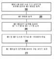
도 18은 많은 구체예에 따른, 수술 기구 샤프트에 의해 지지된 단부 작동기의 메커니즘과 연결되어 구동되는 구동 샤프트의 회전으로부터 수술 기구 샤프트의 회전을 해제하는 방법의 단계들을 예시한다.
도 19는 많은 구체예에 따른, 도 18의 방법의 실시에 사용될 수 있는 케이블-구동 단차에 관한 단계들을 예시한다.
도 20은 많은 구체예에 따른, 도 18의 방법의 실시에 사용될 수 있는 또 다른 케이블-구동 단차에 관한 단계들을 예시한다.
도 21은 많은 구체예에 따른, 도 18의 방법의 실시에 사용될 수 있는 단차 기어 조립체에 관한 단계들을 예시한다.
도 22는 많은 구체예에 따른, 회전가능한 메인 샤프트 내의 2개의 오프셋 구동 샤프트를 가진 로봇 조립체를 도식적으로 예시한다.
도 23은 많은 구체예에 따른, 도 22의 로봇 조립체의 구성요소들과 컨트롤러의 통합을 도식적으로 예시한다.
도 24는 많은 구체예에 따른, 로봇 도구와 관련된 로봇 시스템을 도식적으로 예시한다.
도 25는 많은 구체예에 따른, 구동 모터가 단부 작동기와 단부 작동기를 지지하는 메인 샤프트에 연결되어 메인 샤프트의 의도치 않은 회전을 피할 수 있는 수술 조립체를 도식적으로 예시한다.
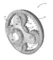
도 26은 많은 구체예에 따른, 행성형 기어 조립체의 투시도이다.
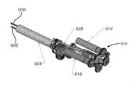
도 27a는 많은 구체예에 따른, 독립적으로 회전가능한 메인 샤프트 및 각 내부 구동 샤프트와 연결된 구동 모터를 포함하며, 이로써 구동 샤프트에 의해 단부 작동기에 전달되는 작동 토크로 인한 메인 샤프트의 의도치 않은 회전을 피할 수 있는 최소 침습 수술 기구 조립체의 투시도이다.
도 27b는 모터 팩 내의 구동 모터를 메인 샤프트 및 각 내부 구동 샤프트와 연결하는 모터 팩과 구동 커플링을 예시하는 도 27a의 기구 조립체의 분해조립 투시도이다.
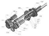
도 28a는 구동 모터를 메인 샤프트 및 각 내부 구동 샤프트와 회전 연결하는데 사용된 구성요소들과 구동 모터를 예시하는 도 27a의 기구 조립체의 내부 구성요소들의 투시도이다.
도 28b는 도 28b에 상응하는 해제된 상태에서 도 28a의 내부 구성요소들을 예시하는 분해조립 투시도이다.
도 29a는 구동 모터 중 하나와 메인 샤프트 및 각 내부 구동 샤프트의 커플링과 관련된 도 29a의 내부 구성요소들을 예시하는 투시도이다.
도 29b는 도 29a의 내부 구성요소들의 단부도이다.
도 29c는 도 29b의 단면 A-A를 예시한다.
도 30은 구동 모터를 각 내부 구동 샤프트 및 메인 샤프트와 회전 연결하는데 사용된 구동 모터, 기어 박스 및 기어를 예시하는 도 27a의 기구 조립체의 내부 구성요소들의 투시도이다.
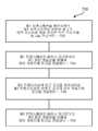
도 31은 많은 구체예에 따른, 단부 작동기에 전달된 작동 토크가 수술 동안 역 구동가능한 메인 샤프트를 회전 구동시키는 것을 방지하기 위한 방법의 순서도이다.1 is a top view of a minimally invasive robotic surgery system used to perform an operation, in accordance with many embodiments.
2 is a perspective view of a pseudo control console for a robotic surgery system, in accordance with many embodiments.
3 is a perspective view of a robotic surgical system electronic cart, in accordance with many embodiments.
Figure 4 schematically illustrates a robotic surgical system, in accordance with many embodiments.
5A is a front view of a patient side cart (surgical robot) of a robotic surgery system, in accordance with many embodiments.
5B is a front view of the robot surgical tool.
6A is a perspective view of a robotic surgical tool including an end effector with opposing clamping jaws, in accordance with many embodiments.
Figure 6b is a close-up perspective view of the end actuator of Figure 6a.
Figure 7 is an exploded assembly perspective view of the end effector of Figure 6a illustrating the mechanism used to convert the rotational movement of the drive shaft to the articulation of the opposed clamping jaws.
8A and 8B are perspective views of an end effector with opposing clamping jaws and a mechanism used to convert the rotational movement of the drive shaft into articulation of the opposing clamping jaws, in accordance with many embodiments.
9 is a simplified perspective view illustrating a drive shaft driven in conjunction with an actuating mechanism of an end effector supported at the distal end of a rotatable instrument shaft, in accordance with many embodiments.
10 is a simplified schematic diagram illustrating creating an output motion used to actuate an end actuator mechanism by combining a first input motion and a mechanism shaft rotation using steps, according to many embodiments.
11A is a simplified schematic plan view illustrating a step by cable used to release mechanism shaft winding and end actuator actuation in a surgical instrument, in accordance with many embodiments.
11B is a simplified schematic side view illustrating the step by cable of FIG. 11A.
Figure 12 is a perspective view illustrating a proximal chassis of a surgical instrument having a cable-driven step used to release instrument shaft winding and end actuator operation in a surgical instrument, in accordance with many embodiments.
13 is a perspective view illustrating a proximal chassis of a surgical instrument having a rowing gearbox used to release mechanism shaft winding and end actuator operation in a surgical instrument, according to many embodiments.
14 is a plan view illustrating a proximal chassis of the surgical instrument of Fig.
15 is a side view illustrating a proximal chassis of the surgical instrument of Fig.
16 is a partial exploded assembly perspective view illustrating a rowing gearbox connected to an input coupler of a surgical instrument, according to many embodiments.
Fig. 17 is an exploded assembly perspective view of the row forming gear box and input coupler of Fig. 16; Fig.
Figure 18 illustrates steps of a method of releasing rotation of a surgical instrument shaft from rotation of a drive shaft driven in conjunction with a mechanism of an end effector supported by a surgical instrument shaft, in accordance with many embodiments.
Figure 19 illustrates steps for a cable-driven step that can be used in the implementation of the method of Figure 18, in accordance with many embodiments.
Figure 20 illustrates steps for another cable-driven step that can be used in the implementation of the method of Figure 18, in accordance with many embodiments.
Figure 21 illustrates steps associated with a stepped gear assembly that may be used in the implementation of the method of Figure 18, in accordance with many embodiments.
Figure 22 schematically illustrates a robot assembly with two offset drive shafts in a rotatable main shaft, in accordance with many embodiments.
Figure 23 diagrammatically illustrates the integration of the controller and the components of the robotic assembly of Figure 22, in accordance with many embodiments.
24 graphically illustrates a robotic system associated with a robotic tool, in accordance with many embodiments.
Figure 25 schematically illustrates a surgical assembly, in accordance with many embodiments, in which a drive motor is connected to a main shaft that supports an end actuator and an end actuator to avoid unintentional rotation of the main shaft.
26 is a perspective view of a row forming gear assembly, in accordance with many embodiments.
27A is a diagrammatic view of an embodiment of the present invention that includes an independently rotatable main shaft and a drive motor coupled to each internal drive shaft, in accordance with many embodiments, whereby unintentional rotation of the main shaft due to actuation torque transmitted to the end actuator by the drive shaft Figure 2 is a perspective view of a minimally invasive surgical instrument assembly that can be avoided.
27B is an exploded assembly perspective view of the instrument assembly of FIG. 27A illustrating a motor pack and drive coupling connecting the drive motor in the motor pack with the main shaft and each internal drive shaft;
28A is a perspective view of the internal components of the instrument assembly of FIG. 27A illustrating the drive motor and the components used to rotationally connect the drive motor to the main shaft and each internal drive shaft;
28B is an exploded assembly perspective view illustrating the internal components of FIG. 28A in a released state corresponding to FIG.
29A is a perspective view illustrating the internal components of Fig. 29A associated with coupling of one of the drive motors with the main shaft and each internal drive shaft.
Figure 29b is an end view of the internal components of Figure 29a.
Figure 29c illustrates section AA of Figure 29b.
30 is a perspective view of the internal components of the instrument assembly of FIG. 27A illustrating the drive motor, gear box, and gear used to rotationally connect the drive motor to each internal drive shaft and main shaft;
31 is a flowchart of a method for preventing an actuating torque transmitted to an end actuator from rotationally driving a main shaft that can be reversed during an operation, according to many embodiments.
다음의 설명에서 본 발명의 다양한 구체예들이 설명될 것이다. 설명의 목적으로 특정한 구성 및 상세한 내용이 제시되며, 이 구체예들의 완전한 이해를 제공할 수 있을 것이다. 그러나, 본 발명이 특정한 상세한 내용 없이도 실시될 수 있다는 것이 당업자에게 자명할 것이다. 또한, 설명된 구체예들이 불명료해 지는 것을 막기 위해서 잘 공지된 특징들은 생략되거나 단순화될 수 있다.In the following description, various embodiments of the present invention will be described. For purposes of explanation, specific configurations and details are set forth, and a complete understanding of these embodiments may be provided. However, it will be apparent to those skilled in the art that the present invention may be practiced without specific details. In addition, well-known features may be omitted or simplified to prevent the described embodiments from becoming obscure.
최소 침습 로봇 수술Minimally invasive robot surgery
도면과 관련하여, 유사한 참조 번호는 몇 개 도면에서 유사한 부품을 나타낸다. 도 1은 최소 침습 로봇 수술(MIRS) 시스템(10)의 평면도이며, 이것은 전형적으로 수술대(14) 위에 누워 있는 환자(12)를 대상으로 최소 침습 진단 또는 수술 과정을 수행하기 위해 사용된다. 이 시스템은 수술 과정 동안 의사(18)가 사용하는 의사 콘솔(16)을 포함할 수 있다. 또한, 1명 이상의 어시스턴트(20)가 수술 과정에 참여할 수 있다. MIRS 시스템(10)은 환자측 카트(22)(수술 로봇)와 전자 카트(24)를 더 포함할 수 있다. 환자측 카트(22)는 의사(18)가 콘솔(16)을 통해 수술 부위를 보면서 환자(12)의 몸에 있는 최소 침습 절개부를 통해서 적어도 하나의 착탈 가능하게 연결된 도구 조립체(26)(이후 간단히 "도구"라고 한다)를 조작할 수 있도록 한다. 입체 내시경과 같은 내시경(28)에 의해서 수술 부위의 영상이 얻어질 수 있으며, 내시경은 환자측 카트(22)에 의해서 조작되며, 이로써 내시경(28)을 배향할 수 있다. 전자 카트(24)를 사용해서는 수술 부위의 영상을 처리할 수 있으며, 처리된 영상은 의사 콘솔(16)을 통해서 의사(18)에서 표시된다. 한번에 사용되는 수술 도구(26)의 수는 일반적으로 진단 또는 수술 과정과 많은 요인들 중에서도 수술실 안에서의 공간적 제약에 좌우될 것이다. 수술 과정 동안 사용되는 하나 이상의 도구(26)를 교체할 필요가 있을 경우, 어시스턴트(20)는 환자측 카트(22)로부터 도구(26)를 제거하고 그것을 수술실의 트레이(30)에 놓여 있는 다른 도구(26)로 교체할 수 있다.In the drawings, like reference numerals designate like parts in several figures. 1 is a top view of a minimally invasive robotic surgery (MIRS)
도 2는 의사 콘솔(16)의 투시도이다. 의사 콘솔(16)은 좌안 디스플레이(32)와 우안 디스플레이(34)를 포함하며, 의사(18)에게 깊이를 투시할 수 있는 수술 부위의 조화된 입체 화면을 표시해준다. 콘솔(16)은 하나 이상의 입력제어 장치(36)를 더 포함하며, 이것에 의해서 환자측 카트(22)(도 1에 도시된)가 하나 이상의 도구를 조작할 수 있다. 입력제어 장치(36)는 관련된 도구(26)(도 1에 도시된)와 동일한 자유도를 제공할 수 있으며, 이로써 원격현시(telepresence), 또는 입력제어 장치(36)가 도구와 일체화되어 의사가 도구(26)를 유효한 감각으로 직접 제어할 수 있는 투시를 의사에게 제공할 수 있다. 이를 위해서, 위치, 힘 및 촉각 피드백 센서(미도시)를 사용해서 위치, 힘 및 촉각 감각을 도구(26)에서 입력제어 장치(36)를 통해 의사의 손에 다시 전송할 수 있다.2 is a perspective view of the
의사 콘솔(16)은 일반적으로 환자와 같은 방에 위치되며, 이로써 의사가 수술 과정을 직접 모니터할 수 있고, 필요하다면 실제 존재하여 전화나 다른 통신 매체를 거치는 것이 아니라 어시스턴트와 직접 대화할 수 있다. 그러나, 의사는 다른 방, 완전히 다른 건물, 또는 원격 수술 과정을 허용하는 환자로부터 떨어진 다른 장소에 있을 수도 있다.The
도 3은 전자 카트(24)의 투시도이다. 전자 카트(24)는 내시경(28)과 연결될 수 있고, 캡처된 영상을 처리할 수 있는 프로세서를 포함할 수 있으며, 캡처된 영상은 의사 콘솔 상에서 또는 국소 및/또는 원격 위치된 다른 적합한 디스플레이 상에서 의사에게 표시된다. 예를 들어, 입체 내시경이 사용된 경우, 전자 카트(24)는 캡처된 영상을 처리해서 수술 부위의 조화된 입체 영상을 의사에게 표시해줄 수 있다. 이러한 조화는 대향하는 영상들 간의 정렬을 포함할 수 있으며, 입체 내시경의 입체 작업 거리를 조정하는 것을 포함할 수 있다. 다른 예로서, 영상 처리는 미리 결정된 카메라 보정 변수의 사용을 포함할 수 있으며, 이로써 광학 수차와 같은 영상 캡처 장치의 영상화 오차를 상쇄할 수 있다.3 is a perspective view of the
도 4는 로봇 수술 시스템(50)(예를 들어 도 1의 MIRS 시스템(10))을 도식적으로 예시한다. 상기 논의된 대로, 의사는 의사 콘솔(52)(예를 들어 도 1의 의사 콘솔(16))을 사용하여 최소 침습 과정 동안 환자측 카트(수술 로봇)(54)(예를 들어 도 1의 환자측 카트(22))를 제어할 수 있다. 환자측 카트(54)는 영상화 장치, 예를 들어 입체 내시경을 사용하여 수술 부위의 영상을 캡처하고, 캡처된 영상을 전자 카트(56)(예를 들어 도 1의 전자 카트(24))에 출력한다. 상기 논의된 대로, 전자 카트(56)는 캡처된 영상을 다양한 방식으로 처리한 후에 표시할 수 있다. 예를 들어, 전자 카트(56)는 캡처된 영상을 가장 제어 인터페이스에 중첩시킨 다음, 조합된 영상을 의사 콘솔(52)을 통해서 의사에게 나타내준다. 환자측 카트(54)는 캡처된 영상을 출력할 수 있으며, 이것은 전자 카트(56) 밖에서 처리된다. 예를 들어, 환자측 카트(54)는 캡처된 영상을 프로세서(58)에 출력하고, 이 프로세서가 캡처된 영상을 처리할 수 있다. 또한, 영상은 전자 카트(56)와 프로세서(58)의 조합에 의해서 처리될 수 있는데, 이것은 함께 연결되어 캡처된 영상을 동시에, 순차적으로 및/또는 이들의 조합 방식으로 처리할 수 있다. 또한, 1개 이상의 별도의 디스플레이(60)가 프로세서(58) 및/또는 전자 카트(56)와 연결될 수 있고, 이것은 수술 부위의 영상이나 다른 관련 영상 등의 영상을 국소 및/또는 원격 표시할 수 있다.Figure 4 illustrates schematically a robotic surgery system 50 (e.g., the
도 5a 및 5b는 환자측 카트(22)와 수술 도구(62)를 각각 도시한다. 수술 도구(62)는 수술 도구(26)의 예이다. 도시된 환자측 카트(22)는 3개 수술 도구(26)와 영상화 장치(28), 예를 들어 수술 부위 영상의 캡처에 사용되는 입체 내시경을 제공한다. 조작은 많은 로봇 조인트를 가진 로봇 메커니즘에 의해 제공된다. 영상화 장치(28)와 수술 도구(26)는 환자의 절개부를 통해서 위치되어 조작될 수 있으며, 이로써 운동학적 원격 중심이 유지되어 절개부의 크기를 최소화할 수 있다. 수술 부위의 영상은 영상화 장치(28)의 시야 안에 위치된 수술 도구(26)의 원단부의 영상을 포함할 수 있다.5A and 5B show the
조직 그립Tissue grip단부End 작동기 Actuator
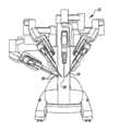
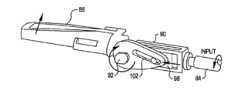
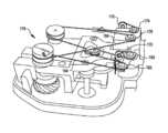
도 6a는 근위부 섀시(72), 기구 샤프트(74), 및 환자 조직을 붙잡을 수 있는 관절식 턱부(78)를 가진 원위부 단부 작동기(76)를 포함하는 수술 도구(70)를 도시한다. 근위부 섀시는 환자측 카트(22)의 아웃풋 커플러와 맞닿아 그에 의해 구동되도록 구성된 인풋 커플러를 포함한다. 이 인풋 커플러는 스프링 조립체(80)의 인풋 링크와 연결되어 구동된다. 스프링 조립체(80)는 근위부 섀시(72)의 프레임(82)에 장착되고, 기구 샤프트(74) 내에 배치된 구동 샤프트와 연결되어 구동되는 아웃풋 링크를 포함한다. 구동 샤프트는 턱부(78)에 연결되어 구동된다. 도 6b는 단부 작동기(76)의 턱부(78)의 근접도이다.6A shows a
도 7은 도 6a의 단부 작동기(76)의 분해조립 투시도로서, 구동 샤프트(84)의 회전 동작을 단부 작동기(76)의 마주 향하면서 클램핑하는 턱부의 관절화로 전환하는데 사용된 클램핑 메커니즘을 예시한다. 단부 작동기는 상부 턱부(86), 하부 턱부(88), 프레임(90), 상부 턱부(86)와 하부 턱부(88)를 프레임(90)에 선회 장착하는 핀(92), 및 구동 샤프트(84)와 연결되어 구동되는 리드-스크루 메커니즘(94)을 포함한다. 리드-스크루 메커니즘(94)은 리드-스크루(96)와 짝을 이루는 직동식 너트(98)를 포함하며, 이 직동식 너트(98)는 리드-스크루(96)의 회전을 통해서 프레임(90)의 슬롯(100)을 따라 전진하고 후퇴한다. 직동식 너트(98)는 상부 턱부(86)의 슬롯(102) 및 하부 턱부(88)의 슬롯(104)과 맞닿은 마주 향하며 연장된 돌출부를 포함하며, 이로써 직동식 너트(98)가 슬롯(100)을 따라 전진하거나 후퇴할 때 핀(92)을 중심으로 상부 턱부(86)와 하부 턱부(88)의 관절화가 야기된다.Figure 7 illustrates an exploded assembly perspective view of the
도 8a 및 도 8b는 도 7의 클램핑 메커니즘과 유사한 클램핑 메커니즘의 작동을 예시한다. 도시된 방향으로 구동 샤프트(84)가 회전하면 직동식 너트(98)가 하부 턱부(88)와 상부 턱부(86)를 단부 작동기의 프레임(90)에 선회 장착시키는 선회 핀(92)을 향해 바깥쪽으로 전진한다. 도 8b에 예시된 대로, 직동식 너트(98)의 돌출부가 상부 턱부(86)의 슬롯(102)과 연동된다. 직동식 너트(98)가 선회 핀(92)을 향해 바깥쪽으로 전진하면 상부 턱부는 도시된 방향으로 회전하게 되고, 반대 방향으로 하부 턱부(88)가 회전하게 되어 이로써 턱부가 열린다. 유사하게, 직동식 너트(98)가 안쪽으로 전진하여 선회 핀(92)으로부터 멀어지면 턱부가 닫히게 된다. 따라서, 턱부는 관절화될 수 있으며 환자 조직을 붙잡을 수 있다.Figures 8A and 8B illustrate the operation of a clamping mechanism similar to the clamping mechanism of Figure 7; When the
도 7, 도 8a 및 도 8b에 도시된 리드-스크루 타입 클램핑 메커니즘은 구동 샤프트에 의해서 전달된 비교적 적은 토크를 비교적 높은 클램핑 힘으로 전환한다는 실질적인 기계적 이점을 제공한다. 이러한 실질적인 기계적 이점을 가진 메커니즘을 통해 과도한 클램핑 힘에 조직이 노출되는 것을 피하기 위해서 구동 샤프트에 의해서 클램핑 메커니즘으로 전달되는 토크가 제어될 수 있다.The lead-screw type clamping mechanism shown in Figs. 7, 8A and 8B provides a substantial mechanical advantage of converting a relatively small torque delivered by the drive shaft to a relatively high clamping force. The torque transmitted to the clamping mechanism by the drive shaft can be controlled to avoid exposing the tissue to excessive clamping force through a mechanism with this substantial mechanical advantage.
교대형School building단부End 작동기 메커니즘 Actuator mechanism
구동 샤프트(84)를 사용해서 어떤 적합한 단부 작동기 메커니즘이라도 작동시킬 수 있다. 예를 들어, 구동 샤프트(84)를 사용해서 조직 스테플링 메커니즘, 조직 컷팅 메커니즘과 같은 메커니즘과 일반적으로 회전 인풋에 의해서 작동될 수 있는 적합한 단부 작동기 메커니즘을 작동시킬 수 있다.Any suitable end actuator mechanism can be actuated using
기구 샤프트 감김과Mechanism shaft winding단부End 작동기 작동의 해제 Deactivation of actuator
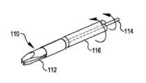
도 9는 수술 기구에서 기구 샤프트 감김과 단부 작동기 작동의 해제를 논의하기 위한 적절한 시작점을 제공한다. 도 9는 어떤 것(예를 들어, 환자 조직, 봉합 바늘 등)을 붙잡을 수 있는 관절식 턱부(112)를 포함하는 단부 작동기(110)를 도시한다. 단부 작동기(110)는 관절식 턱부(112)와 같은 단부 작동기(110)의 메커니즘을 작동시키기 위한 작동 메커니즘을 포함한다. 이 작동 메커니즘은 구동 샤프트(114)에 연결되어 구동된다. 단부 작동기(110)는 기구 샤프트(116)의 원단부에서 지지된다. 기구 샤프트(116)는 기구 샤프트(116)를 지지하는 근위부 섀시 베이스에 대해 회전 범위 내에서 회전할 수 있다. 마찬가지로, 구동 샤프트(114)도 근위부 섀시 베이스에 대해 회전 범위 내에서 회전할 수 있다.Figure 9 provides an appropriate starting point for discussing the mechanism shaft winding and release of end effector operation in the surgical instrument. Figure 9 shows an
구동 샤프트(114)가 기구 샤프트(116)의 회전과 무관하게 구동될 경우, 단부 작동기 턱부(112)를 작동시키는데 사용될 수 있는 근위부 섀시 베이스에 대한 구동 샤프트(114)의 회전 범위 부분은 근위부 섀시 베이스에 대한 기구 샤프트(116)의 회전 범위만큼 감소한다. 예를 들어, 베이스에 대한 기구 샤프트(116)의 회전 범위가 2 회전수이고, 베이스에 대한 구동 샤프트(114)의 회전 범위가 10 회전수일 때, 단부 작동기(110)에 대한 구동 샤프트(114)의 순 회전 범위는 8 회전수가 된다. 다시 말해서, 이러한 두 분리된 2 회전수는 조합되었을 때 단부 작동기(110)의 작동 메커니즘에 대한 구동 샤프트(114)의 순 회전을 0으로 만들므로 베이스에 대한 구동 샤프트(114)의 회전수 중 2는 베이스에 대한 기구 샤프트(116)의 2 회전수에 의해 유효하게 무효가 된다.The rotational range portion of the
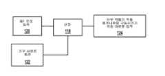
도 10은 단차(118)를 사용해서 제1 인풋 동작(120)을 기구 샤프트 회전(122)과 조합하여 아웃풋 동작(124)을 생성함으로써 단부 작동기 작동 메커니즘을 구동시키는 것을 도식적으로 예시한다. 단차(118)는 근위부 섀시 베이스에 대한 구동 샤프트(114)의 회전량과 단부 작동기 작동 메커니즘에 대한 구동 샤프트(114)의 상응하는 회전량의 차이가 생기는 것에 대한 기구 샤프트의 상기 논의된 영향을 상쇄하도록 구성될 수 있다. 예를 들어, 단차(118)는 근위부 섀시 베이스에 대한 시계방향 2 회전수의 제1 인풋 동작(120)과 근위부 섀시 베이스에 대한 시계방향 1 회전수의 기구 샤프트 동작(122)을 조합하도록 구성될 수 있고, 이로써 근위부 섀시 베이스에 대한 시계방향 3 회전수의 아웃풋 동작(124)이 야기되며, 이것은 단부 작동기에 대한 시계방향 2 회전수의 아웃풋 동작을 효과적으로 제공한다. 또한, 이러한 단차 구성은 구동 샤프트(114)와 기구 샤프트(116)가 반대 방향으로 회전될 때 기구 샤프트 회전의 상기 논의된 영향을 상쇄하는데 쓰인다. 예를 들어, 이러한 단차 구성에 있어서, 근위부 섀시 베이스에 대한 제1 인풋 동작(120)의 시계방향 2 회전수가 베이스에 대한 기구 샤프트(122)의 반시계방향 1 회전수와 조합되어 베이스에 대한 시계방향 1 회전수의 아웃풋 동작(124)이 야기되며, 이것은 단부 작동기에 대한 아웃풋 동작에서 시계방향 2 회전수의 아웃풋 동작을 효과적으로 야기한다.10 schematically illustrates driving the end effector actuating mechanism by combining the
단차는 근위부 섀시 베이스에 대한 구동 샤프트의 회전량과 단부 작동기 작동 메커니즘에 대한 구동 샤프트의 상응하는 회전량의 차이가 생기는 것에 대한 기구 샤프트 회전의 상기 논의된 영향을 전부 실질적으로 상쇄하도록 구성되는 것이 바람직하지만, 이 단차는 또한 적당한 정도로만 기구 샤프트 회전의 영향을 상쇄하도록 구성될 수도 있다. 예를 들어, 단차는 수술 기구의 원하는 작동 특징을 달성하기에 적합하도록 기구 샤프트 회전의 상기 논의된 영향에서 이 영향을 덜 상쇄하고, 더 상쇄하고, 고르게 증폭하도록 구성될 수 있다.It is preferred that the step is configured to substantially cancel out all of the discussed effects of mechanism shaft rotation on the occurrence of the difference between the amount of rotation of the drive shaft relative to the proximal chassis base and the corresponding amount of rotation of the drive shaft relative to the end effector operating mechanism However, this step may also be configured to offset the effect of the mechanism shaft rotation only to a reasonable extent. For example, the step can be configured to less offset, more cancel, and even amplify this effect in the discussed effects of instrument shaft rotation to be suitable to achieve the desired operating characteristics of the surgical instrument.
단차는 어떤 적합한 방식으로도 실행될 수 있다. 예를 들어, 단차는 케이블과 도르래를 사용하여 실행될 수 있다. 또 다른 예로서, 단차는 행성형 기어 박스 조립체와 같은 기어 장치를 사용하여 실행될 수 있다.The steps may be executed in any suitable manner. For example, the steps may be implemented using cables and pulleys. As another example, the steps may be performed using a gear device such as a row forming gearbox assembly.
케이블에 의한By cable단차Step
도 11a는 여러 구체예에 따른, 로봇 수술 기구에서 기구 샤프트 감김과 단부 작동기 작동을 해제하기 위해 사용되는 케이블에 의한 단차(130)를 예시한다. 이 단차(130)는 근위부 섀시 베이스에 대해 기구 샤프트와 함께 회전하도록 연결된 롤 도르래(132), 작동 기원과 함께 회전하도록 연결된 단부 작동기 작동 도르래(134), 및 단부 작동기 턱부 작동 메커니즘과 함께 회전하도록 연결된 리드-스크루 드라이브 도르래(136)를 포함한다. 롤 도르래(132)와 리드-스크루 드라이브 도르래(136) 양자와 연동된 제1 케이블(138)은 롤 도르래(132)의 회전에 응해서 리드-스크루 드라이브 도르래(136)의 회전을 제공한다. 단부 작동기 작동 도르래(134)와 연동된 제2 케이블(140)은 제1 도르래 블록(142) 및 제2 도르래 블록(144)과 연결된다. 제1 도르래 블록(142)은 제1 무빙 도르래(146)를 포함한다. 그리고 제2 도드래 블록(144)은 제2 무빙 도르래(148)를 포함한다. 제1 및 제2 무빙 도르래(146, 148)는 제1 케이블(138)과 연동된다.11A illustrates a
롤 도르래(132)와 리드-스크루 드라이브 도르래(136) 사이에서 제1 케이블이 4개의 고정된 가이드 도르래와 연동된다. 이들 고정된 가이드 도르래는 제1 가이드 도르래(150), 제2 가이드 도르래(152), 제3 가이드 도르래(154) 및 제4 가이드 도르래(156)를 포함한다.Between the
도 11b는 케이블에 의한 단차(130)의 측면도이다. 롤 도르래(132)가 나선형 기어(158)를 통해 기구 샤프트와 함께 회전하도록 연결된다. 롤 도르래(132)와 나선형 기어(158)는 회전축(160)을 중심으로 회전한다. 기구 샤프트는 나선형 기어 회전축(160)을 횡단하는 방향의 회전축을 중심으로 회전한다. 기구 샤프트와 함께 회전하도록 부착된 짝을 이루는 나선형 기어와 나선형 기어(158)는 기구 샤프트의 회전을 롤 도르래(132)의 회전으로 전달한다.11B is a side view of the
4개의 고정된 가이드 도르래(150, 152, 154, 156)는 제1 케이블(138)의 위치를 수평, 수직 양쪽으로 구속하는데 쓰인다. 제1 및 제3 가이드 도르래(150, 154)는 제2 및 제4 가이드 도르래(152, 156) 밑에 위치하며, 제1 케이블(138)의 중첩된 부분들 사이에 수직 분리를 제공한다. 제1 및 제3 가이드 도르래(150, 154)는 또한 수평으로 위치되며, 제1 무빙 도르래(146)가 이동하는 전 범위에서 제1 무빙 도르래(146)와 제1 케이블(138)의 180도 연동을 제공한다. 마찬가지로, 제2 및 제4 가이드 도르래(152, 156)도 역시 수평으로 위치되어 제2 무빙 도르래(148)가 이동하는 전 범위에서 제2 무빙 도르래(148)와 제1 케이블(138)의 180도 연동을 제공한다.Four fixed guide sheaves 150, 152, 154 and 156 are used to restrain the position of the
케이블에 의한 단차(130)는 롤 도르래(132)의 동작과 단부 작동기 작동 도르래(134)의 동작을 조합해서 리드-스크루 드라이브 도르래(136)의 동작을 야기한다. 예를 들어, 단부 작동기 작동 도르래(134)가 회전하지 않을 때는 롤 도르래(132)의 회전이 리드-스크루 드라이브 도르래(136)에 상응하는 회전을 일으키고, 결과적으로 리드-스크루 드라이브 도르래(136)의 순 회전은 단부 작동기 턱부 작동 메커니즘에 대응하지 않게 된다. 롤 도르래(132)가 회전하지 않을 때는 단부 작동기 작동 도르래(134)의 회전이 제1 및 제2 무빙 도르래(146, 148)에 상응하는 동작을 일으키고, 이로써 리드-스크루 도르래(136)가 회전하게 된다. 롤 도르래(132)와 단부 작동기 작동 도르래(134) 양자가 동시에 회전하여 제1 케이블(138)과 제2 케이브(140)의 상응하는 움직임이 리드-스크루 드라이브 도르래(136)에 회전을 일으키며, 이것은 롤 도르래(132)와 단부 작동기 작동 도르래(134)의 회전이 조합된 것이다.The
도 12는 여러 구체예에 따른, 케이블에 의한 단차(170)를 가진 로봇 수술 기구의 근위부 섀시의 투시도이다. 케이블에 의한 단차(170)는 수평 및 수직으로 제1 케이블(184)을 구속하기 위해 6개의 고정된 가이드 도르래(172, 174, 176, 178, 180, 182)를 포함하는 것을 제외하면 케이블에 의한 단차(130)와 유사하게 구성된다.12 is a perspective view of a proximal chassis of a robotic surgical instrument having a
어떤 적합한 케이블에 의한 단차라도 사용될 수 있다. 예를 들어, 케이블에 의한 단차(130)의 변형에서는 제1 케이블(138)이 단부 작동기 작동 도르래(134)에 의해서 구동되고, 제2 케이블(140)이 롤 도르래(132)에 의해서 구동된다.Any step by any suitable cable can be used. For example, in the deformation of the
기어에 의한By gear단차Step
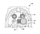
도 13은 여러 구체예에 따른, 기어에 의한 단차(192)를 포함하는 로봇 수술 기구의 근위부 섀시(190)의 투시도이다. 기어에 의한 단차(192)는 중심 기어, 캐리어에 연결된 행성 기어, 및 링 기어를 가진 행성형 기어 조립체를 포함한다. 캐리어는 인풋 샤프트를 통해 근위부 섀시의 인풋 커플러와 함께 회전하도록 연결된다. 인풋 샤프트는 인풋 커플러와 정렬되며 기구 샤프트를 횡단한다. 중심 기어는 나선형 기어(194, 196)를 통해 기구 샤프트(116)와 함께 회전하도록 연결된다. 캐리어와 중심 기어의 회전은 링 기어의 회전으로 이어진다. 링 기어는 나선형 기어(198, 200), 아웃풋 샤프트(202), 및 기구 샤프트(116)의 내부로 이어진 구동 샤프트를 통해 단부 작동기 작동 메커니즘과 함께 회전하도록 연결된다. 도 14는 근위부 섀시(190)와 기어에 의한 단차(192)의 평면도이다. 도 15는 또한 근위부 섀시(190)와 기어에 의한 단차(192)의 측면도이다.13 is a perspective view of a
도 16 및 도 17은 여러 구체예에 따른, 기어에 의한 단차(210)를 상세히 예시하는 분해조립도이다. 기어에 의한 단차(210)는 행성형 기어 박스 조립체(212)를 포함한다. 도 16은 기어에 의한 단차(210)와 측로에 배치되어 부착된 인풋 샤프트 및 인풋 커플러(214)를 도시하며, 이들은 측로로부터 기구 샤프트(116)를 가진 로봇 수술 기구의 근위부 섀시(216)에 설치된다. 기어에 의한 단차(210)의 설치 중심선(218)과 중심축(220)은 설치 위치로부터의 오프셋을 예시한다.Figures 16 and 17 are exploded assembly views detailing the
도 17은 기어에 의한 단차(210), 인풋 샤프트, 및 인풋 커플러(214)의 분해조립 투시도이다. 단차(210)는 행성 기어(224)와 연결된 캐리어(222), 인풋 기어(228)에 의해 회전 구동되는 중심 기어(226), 내부 링 기어를 가진 링 기어 부재(230) 및 외부 나선형 아웃풋 기어(232)를 포함한다. 캐리어(222)는 인풋 샤프트(234)에 연결되어 그에 의해 회전 구동되고, 인풋 샤프트는 인풋 커플러(214)와 연결되어 그에 의해 회전 구동된다. 인풋 커플러(214)는 근위부 섀시(216)가 로봇 암에 장착되었을 때 수술 로봇의 로봇 암에서 상응하는 아웃풋 커플러와 맞닿아 그에 의해 회전 구동된다. 캐리어(222)의 회전은 중심축(220)을 중심으로 행성 기어(224)의 중심선의 회전으로 이어진다. 인풋 기어(228)는 기구 샤프트(116)와 함께 회전하도록 연결된다. 중심축(220)을 중심으로 행성 기어(224)의 중심선과 중심 기어(226)의 조합된 회전은 중심축(220)을 중심으로 링 기어 부재(230)의 상응하는 회전으로 이어진다. 링 기어 부재(230)는 외부 나선형 아웃풋 기어(232)를 통해 단부 작동기 작동 메커니즘과 연결되어 구동된다.17 is an exploded assembly perspective view of the
기어에 의한 단차(210)는 캐리어(222)와 근위부 섀시(216) 사이에 연결된 토션 스프링(236)을 포함한다. 토션 스프링은 로봇 암에서 캐리어와 작동 기원의 연결이 해제된 후 캐리어를 정해진 위치로 되돌리며, 이로써 단부 작동기 작동 메커니즘도 정해진 구성으로 되돌아 간다.The stepped
작동 중에 기어에 의한 단차(210)는 상기 논의된 단차(118)와 유사하게 작동한다. 공지된 접근법에 따른 추가의 기어 장치를 사용하여 기구 샤프트(116)와 외부 나선형 아웃풋 기어(232)의 결과의 아웃풋 동작 사이의 방향 및 회전 속도 차이를 설명할 수 있다.The
행성형 기어 박스 변수의 예Examples of Rowing Gearbox Variables
다음 식은 중심 기어(226)와 캐리어(222)와 링 기어 부재(230)의 회전 사이의 관계를 제공한다.The following equation provides the relationship between the
(식 1)(Equation 1)

식 (1)에 나타낸 대로, 링 기어 부재(230)의 각속도는 중심 기어(226)의 각속도와 캐리어(222)의 각속도의 선형 조합이다. 따라서, 기어에 의한 단차(210)에 있어서(이 경우 중심 기어(226)가 기구 샤프트(116)의 회전에 의해 구동되어 회전되고, 캐리어(222)는 인풋 커플러(214)에 의해 구동되어 회전되며, 링 기어 부재(230)는 단부 작동기 작동 메커니즘과 연결되어 회전된다), 기구 샤프트(116)의 회전은 링 기어 부재(230)의 상응하는 추가 회전으로 이어지고, 이로써 기구 샤프트 회전이 단부 작동기 작동 메커니즘의 작동으로부터 해제된다.As shown in equation (1), the angular velocity of the
다음 변수들은 기어에 의한 단차(210)에서 행성형 기어 박스 구성의 일례를 제공한다.The following variables provide an example of a row molding gearbox configuration at

캐리어 각속도가 0인 경우(인풋 커플러(214)를 통한 회전 인풋이 없을 때에 해당한다) 식 (1)은 다음과 같이 줄어든다:If the carrier angular velocity is zero (corresponding to no rotational input through the input coupler 214), equation (1) is reduced to:

행성형 기어 박스 변수들의 상기 예에서 n=2인 경우 링 기어 부재의 각속도(ωa)와 중심 기어의 각속도(ωs) 사이에는 다음 관계가 성립한다:In the above example of the row forming gearbox variables, the relationship is established between the angular speed (?A ) of the ring gear member and the angular speed (?S ) of the center gear when n = 2:

중심 기어(226)와 링 기어 부재(230)의 회전 방향 차이를 설명하고, 단부 작동기 작동 메커니즘에 연결되어 회전되는 구동샤프트의 회전량을 기구 샤프트(116)의 회전량과 같게 하기 위해서, 공지된 접근법을 이용한 추가의 기어 장치가 기구 샤프트(116)과 중심 기어(226) 사이에, 및/또는 링 기어 부재(230)와 단부 작동기 작동 메커니즘에 연결되어 회전되는 구동 샤프트 사이에 사용될 수 있다.In order to explain the rotational direction difference between the
수술 조립체 적용Application of surgical assembly
여기 개시된 수술 조립체는 어떤 적합한 용도에 이용될 수 있다. 예를 들어, 여기 개시된 수술 조립체는 개복 또는 최소 침습(단일 또는 멀티-포트) 과정을 위한 수동 또는 전기 방식 핸드헬드 또는 로봇 방식 직접 제어 또는 원격조종 방식의 여러 수술 기구들에 이용될 수 있다. 이러한 기구들의 예는 인풋을 작동시키는 토크를 수용하는 원위부 구성요소를 가진 것들을 포함한다(예를 들어, 그립 제어 기능, 구성요소 배향 제어 기능, 구성요소 배치 기능 등을 위한). 예시적인 비제한적 예들은 스테이플링, 컷팅, 조직 퓨징, 영상화 장치 배향 및 배치 제어, 강한 힘의 그래스핑, 바이옵시, 및 단부 작동기 및 배향 제어를 포함하는 원격조종 또는 핸드헬드 기구들을 포함한다.The surgical assembly disclosed herein may be used for any suitable application. For example, the surgical assembly disclosed herein may be used in a variety of surgical instruments in a manual or electric handheld or robotic direct or remote controlled manner for an open or minimally invasive (single or multi-port) procedure. Examples of such mechanisms include those having a distal component (e.g., grip control function, component orientation control function, component placement function, etc.) that accept torque to actuate the input. Exemplary, non-limiting examples include remote manipulation or handheld mechanisms including stapling, cutting, tissue fusing, imaging device orientation and placement control, strong force grinding, biaxial, and end effector and orientation control.
기구 샤프트 감김과Mechanism shaft winding단부End 작동기 작동을 해제하는 방법 How to disable the actuator
도 18은 많은 구체예에 따른, 수술 기구 샤프트에 의해 지지된 단부 작동기의 메커니즘과 연결되어 구동되는 구동 샤프트의 회전으로부터 수술 기구 샤프트의 회전을 해제하는 방법(250)의 단계들을 예시한다. 이 방법(250)은, 예를 들어 어떤 적합한 단차, 예를 들어 상기 설명된 단차(118), 케이블에 의한 단차(130), 케이블에 의한 단차(170) 및 기어에 의한 단차(192) 중 어느 것을 사용함으로써 실시될 수 있다. 상기 방법(250)은 소정의 단부 작동기 구성과 관련된 제1 인풋 동작을 생성하는 단계(단계 252); 베이스에 인접한 근단부와 단부 작동기를 지지하는 원단부 사이에서 연장된 수술 기구 샤프트를 베이스에 대해 회전시키는 단계(단계 254); 베이스에 대한 수술 기구 샤프트의 회전에 응하여 제2 인풋 동작을 생성하는 단계(단계 256); 제1 인풋 동작과 제2 인풋 동작을 조합해서 아웃풋 동작을 생성하는 단계(단계 258); 및 아웃풋 동작에 응하여 구동 샤프트를 회전시키는 단계(단계 260)를 포함한다. 많은 구체예에서, 제1 인풋 동작과 제2 인풋 동작은 제1 인풋 동작이 제로일 때는 수술 기구에 대한 구동 샤프트의 실질적인 회전이 일어나지 않도록 조합된다.Figure 18 illustrates steps of a
도 19는 여기 설명된 것들 중 어느 것과 같은, 케이블에 의한 단차를 이용하여 방법(250)을 실시하는데 사용될 수 있는 단계들을 예시한다. 이 단계들은 베이스에 대한 수술 기구 샤프트의 회전에 응하여 제1 케이블을 움직이는 단계(단계 262); 제2 케이블을 움직이는 단계(단계 264); 제2 케이블의 움직임에 응하여 제1 도르래 및 제2 도르래를 움직이는 단계(단계 266); 제1 케이블을 제1 및 제2 도르래와 각각 연동되는 단계(단계 268); 및 제1 케이블의 움직임에 응하여 구동 샤프트를 회전시키는 단계(단계 270)를 포함한다. 많은 구체예에서, 제1 케이블은 각 도르래에서 약 180도 구간에 걸쳐서 제1 및 제2 도르래와 각각 연동된다.FIG. 19 illustrates steps that may be used to implement
도 20은 여기 설명된 것들 중 어느 것과 같은, 케이블에 의한 단차를 이용하여 방법(250)을 실시하는데 사용될 수 있는 단계들을 예시한다. 이 단계들은 제1 케이블을 움직이는 단계(단계 272); 베이스에 대한 수술 기구 샤프트의 회전에 응하여 제2 케이블을 움직이는 단계(단계 274); 제2 케이블의 움직임에 응하여 제1 도르래 및 제2 도르래를 움직이는 단계(단계 276); 제1 케이블을 제1 및 제2 도르래와 각각 연동되는 단계(단계 278); 및 제1 케이블의 움직임에 응하여 구동 샤프트를 회전시키는 단계(단계 280)를 포함한다. 많은 구체예에서, 제1 케이블은 각 도르래에서 약 180도 구간에 걸쳐서 제1 및 제2 도르래와 각각 연동된다.FIG. 20 illustrates steps that may be used to implement
도 21은 여기 설명된 것들 중 어느 것과 같은, 기어에 의한 단차를 이용하여 방법(250)을 실시하는데 사용될 수 있는 단계들을 예시한다. 이 단계들은 제1 인풋 동작에 응하여 단차 기어 조립체의 제1 인풋 링크를 회전시키는 단계(단계 282), 제2 인풋 동작에 응하여 단차 기어 조립체의 제2 인풋 링크를 회전시키는 단계(단계 284), 및 단차 기어 조립체의 아웃풋 링크의 회전에 응하여 구동 샤프트를 회전시키는 단계(단계 286)를 포함한다.FIG. 21 illustrates steps that may be used to implement
방법 적용Apply method
여기 개시된 방법은 어떤 적합한 용도에 이용될 수 있다. 예를 들어, 여기 개시된 방법은 개복 또는 최소 침습(단일 또는 멀티-포트) 과정을 위한 수동 또는 전기 방식 핸드헬드 또는 로봇 방식 직접 제어 또는 원격조종 방식의 수술 기구들에 이용될 수 있다. 이러한 기구들의 예는 인풋을 작동시키는 토크를 수용하는 원위부 구성요소를 가진 것들을 포함한다(예를 들어, 그립 제어 기능, 구성요소 배향 제어 기능, 구성요소 배치 기능 등을 위한). 예시적인 비제한적 예들은 스테이플링, 컷팅, 조직 퓨징, 영상화 장치 배향 및 배치 제어, 강한 힘의 그래스핑, 바이옵시, 및 단부 작동기 및 배향 제어를 포함하는 원격조종 또는 핸드헬드 기구들을 포함한다.The methods disclosed herein may be used for any suitable application. For example, the methods disclosed herein can be used in manual or electric handheld or robotic direct control or remotely controlled surgical instruments for laparoscopic or minimally invasive (single or multi-port) procedures. Examples of such mechanisms include those having a distal component (e.g., grip control function, component orientation control function, component placement function, etc.) that accept torque to actuate the input. Exemplary, non-limiting examples include remote manipulation or handheld mechanisms including stapling, cutting, tissue fusing, imaging device orientation and placement control, strong force grinding, biaxial, and end effector and orientation control.
회전가능한Rotatable 샤프트 내의 구동 샤프트(들) The drive shaft (s)
도 22는 회전가능한 메인 샤프트 내에 2개의 오프셋 구동 샤프트를 가진 로봇 조립체(370)를 도식적으로 예시한다. 로봇 조립체(370)는 회전가능한 메인 샤프트(374)의 원단부와 연결된 단부 작동기(372), 및 메인 샤프트(374)와 단부 작동기(372)와 모두 연결된 작동 조립체(376)를 포함한다.22 schematically illustrates a
단부 작동기(372)는 단부 작동기 베이스, 제1 작동 메커니즘(378), 제2 작동 메커니즘(380) 및 제어 케이블 메커니즘(들)(382)을 포함한다. 단부 작동기 베이스는 회전가능한 메인 샤프트(374)에 연결되어 선회된다. 제1 작동 메커니즘(378)과 제2 작동 메커니즘(380)은 샤프트 구동되며, 여러 단부 작동기 특징부 및/또는 장치, 예를 들어 클램핑 특징부, 움직이는 컷팅 특징부, 커팅 및 스테이플링 장치, 또는 샤프트 구동 메커니즘에 의해 작동되고/되거나 관절화될 수 있는 다른 적합한 단부 작동기 특징부 및/또는 장치를 작동시키고/시키거나 관절화하는데 사용될 수 있다. 제어 케이블 메커니즘(들)(382)도 또한 여러 단부 작동기 특징부 및/또는 장치, 특히 빠른 반응이 바람직한 것들, 예를 들어 그래스핑 특징부, 메인 샤프트에 대한 단부 작동기 베이스를 관절화하는데 사용되는 단부 작동기 베이스 리스트에 대한 메인 샤프트, 또는 하나 이상의 제어 케이블을 통해서 작동되고/되거나 관절화될 수 있는 다른 적합한 특징부 및/또는 장치를 작동시키고/시키거나 관절화하는데 사용될 수 있다.The
단부 작동기 베이스는 회전가능한 메인 샤프트(374)와 연결되며, 이로써 메인 샤프트 회전축을 중심으로 한 메인 샤프트(374)의 회전이 단부 작동기 베이스의 상응하는 회전을 생성한다. 상기 논의된 대로, 메인 샤프트(374)를 독립적으로 회전시키는 능력은 비-회전성 메인 샤프트에 비해 단부 작동기 조작능을 증가시키며, 이것은 특정한 수술 과정 동안, 예를 들어 특정한 최소 침습 수술 과정 동안 유리할 수 있다. 또한, 단부 작동기 베이스는 추가의 단부 작동기 조작능을 제공하는 적합한 리스트 메커니즘(384)을 가진 회전가능한 메인 샤프트(374)와 연결될 수 있다.The end actuator base is connected to a rotatable
2개의 구동 샤프트를 사용해서 단부 작동기 샤프트 구동 작동 메커니즘을 구동시킨다. 제1 구동 샤프트(386)는 메인 샤프트 회전축으로부터 오프셋된 제1 구동 샤프트 회전축을 중심으로 한 회전을 위해 장착된다. 제1 구동 샤프트(386)는 제1 작동 메커니즘(378)과 연결되어 작동된다. 마찬가지로, 제2 구동 샤프트(388)는 메인 샤프트 회전축으로부터 오프셋된 제2 구동 샤프트 회전축을 중심으로 한 회전을 위해 장착된다. 제2 구동 샤프트(388)는 제2 작동 메커니즘(380)과 연결되어 작동된다.Two drive shafts are used to drive the end actuator shaft drive operating mechanism. The
작동 조립체(376)는 회전가능한 메인 샤프트(374), 제1 구동 샤프트(386), 제2 구동 샤프트(388) 및 제어 케이블 메커니즘(들)(382)과 연결된다. 회전가능한 메인 샤프트(374)는 작동 조립체(376)의 베이스에 대한 회전을 위해 장착된다. 작동 조립체(376)는 베이스에 대한 회전가능한 메인 샤프트(374)의 회전을 생성하도록 작동된다. 또한, 작동 조립체(376)는 베이스에 대한 회전가능한 메인 샤프트(374)의 회전, 회전가능한 메인 샤프트(374)에 대한 제1 구동 샤프트(386)의 회전, 및 회전가능한 메인 샤프트(374)에 대한 제1 구동 샤프트(388)의 회전의 어떤 조합을 생성하도록 작동된다. 이와 같이, 제1 작동 메커니즘(378) 및/또는 제2 작동 메커니즘(380)은 독립적으로 및/또는 회전가능한 메인 샤프트(374)의 회전과 동시에 작동될 수 있다.The actuation assembly 376 is connected to a rotatable
작동 조립체(376)는 제1 구동 샤프트(386)와 제2 구동 샤프트(388)가 베이스에 대한 회전가능한 메인 샤프트(374)가 회전하는 동안에도 회전가능한 메인 샤프트(374)에 대해 독립적으로 회전될 수 있는 상기 설명된 기능성을 제공하도록 구성된다. 작동 조립체(376)는 메인 샤프트 인코더(392) 및 메인 샤프트 인터페이스(394)와 연결된 메인 샤프트 모터(390), 제1 인코더(398) 및 제1 인터페이스(400)와 연결된 제1 모터(396), 제2 인코더(404) 및 제2 인터페이스(406)와 연결된 제2 모터(402), 및 제어 케이블 인코더(들)(410) 및 제어 케이블 인터페이스(들)(412)와 연결된 제어 케이블 모터(들)(408)를 포함한다. 메인 샤프트 인터페이스(394)는 회전가능한 메인 샤프트(374)와 연결되며, 이로써 회전 동작을 메인 샤프트 모터(390)로부터 회전가능한 메인 샤프트(374)로 전달할 수 있다. 메인 샤프트 모터(390)는 베이스에 고정 연결될 수 있으며, 이로써 전달된 회전 동작이 베이스에 대한 회전가능한 메인 샤프트(374)의 회전을 일으킨다. 메인 샤프트 인코더(392)는 메인 샤프트 모터(390), 메인 샤프트 인터페이스(394) 및/또는 회전가능한 메인 샤프트(374)의 배향을 측정하며, 컨트롤러(도 22에는 미도시)와 연결되어 컨트롤러에 측정된 배향을 제공할 수 있다. 제1 인터페이스(400)는 제1 구동 샤프트(386)와 연결되어 회전가능한 메인 샤프트(374)의 어떤 배향 및/또는 회전 동작 동안 회전 동작을 제1 모터(396)로부터 제1 구동 샤프트(386)에 전달하도록 작동될 수 있다. 제1 인코더(398)는 제1 모터(396), 제1 인터페이스(400) 및/또는 제1 구동 샤프트(386)의 배향을 측정하며, 컨트롤러와 연결되어 컨트롤러에 측정된 배향을 제공할 수 있다. 제2 인터페이스(406)는 제2 구동 샤프트(388)와 연결되어 회전가능한 메인 샤프트(374)의 어떤 배향 및/또는 회전 동작 동안 회전 동작을 제2 모터(402)로부터 제2 구동 샤프트(388)에 전달하도록 작동될 수 있다. 제2 인코더(404)는 제2 모터(402), 제2 인터페이스(406) 및/또는 제2 구동 샤프트(388)의 배향을 측정하며, 컨트롤러와 연결되어 컨트롤러에 측정된 배향을 제공할 수 있다. 제어 케이블 인터페이스(들)(412)는 제어 케이블 메커니즘(들)(382)과 연결되어 작동되는 제어 케이블(들)(414)과 연결된다. 제어 케이블(들)(414)은 회전가능한 메인 샤프트(374)의 회전 배향 범위를 허용하도록 이어질 수 있으며, 예를 들어 메인 샤프트 회전축 부근에서 이어짐으로써 회전가능한 메인 샤프트(374)의 회전으로 인한 제어 케이블 길이의 변화를 최소화할 수 있고, 제어 케이블(들)의 어떤 꼬임 및/또는 제어 케이블들 간의 꼬임을 허용하도록 구성됨으로써 메인 샤프트(374)의 어떤 회전 배향을 가져올 수 있다(예를 들어, 케이블간 마찰을 견디는 구성을 가짐으로써). 제어 케이블 인코더(들)(410)는 제어 케이블 모터(들)(408) 및/또는 제어 케이블 인터페이스(들)(412)의 배향을 측정하며, 컨트롤러와 연결되어 컨트롤러에 측정된 배향(들)을 제공할 수 있다.The actuation assembly 376 is rotated independently of the
도 23은 많은 구체예에 따른, 컨트롤러(416)와 로봇 조립체(370)의 구성요소들의 통합을 예시하는 단순화된 블럭도이다. 컨트롤러(416)는 적어도 하나의 프로세서(418)를 포함하며, 이것은 버스 서브시스템(420)을 통해서 주변 장치들과 통신한다. 이들 주변 장치들은 전형적으로 저장 서브시스템(422)을 포함한다.23 is a simplified block diagram illustrating the integration of components of
저장 서브시스템(422)은 컨트롤러(416)의 기능성을 제공하는 기본 프로그래밍과 데이터 구축을 유지한다. 상기 논의된 로봇 조립체 기능성을 실시하기 위한 소프트웨어 모듈이 전형적으로 저장 서브시스템(422)에 저장된다. 저장 서브시스템(422)은 전형적으로 메모리 서브시스템(424)과 파일 저장 서브시스템(426)을 포함한다.The
메모리 서브시스템(424)은 전형적으로 프로그램 실행 동안 명령 및 데이터를 저장하는 주 랜덤 액세서 메모리(RAM)(428) 및 고정적인 명령이 저장되는 읽기 전용 메모리(ROM)(430)를 포함하는 많은 메모리를 포함한다.The
파일 저장 서브시스템(426)은 프로그램과 데이터 파일의 영구적인(비휘발성) 저장을 제공하며, 하드 드라이브, 디스크 드라이브, 또는 플래시 메모리와 같은 다른 비휘발성 메모리를 포함할 수 있다. 입력 장치, 예를 들어 디스크 드라이브를 사용하여 상기 논의된 소프트웨어 모듈을 입력할 수 있다. 또는 달리, USB 포트와 같은 다른 공지된 구조들을 대신 사용하여 소프트웨어 모듈을 입력할 수 있다.
이 맥락에서, 용어 "버스 시스템"은 본질적으로 다양한 구성요소들과 서브시스템이 의도된 대로 서로 통신하도록 하는 어떤 메커니즘을 포함하도록 사용된다. 버스 시스템(420)은 단일 버스로서 도식적으로 도시되지만, 전형적인 시스템은 로컬 버스 및 하나 이상의 확장형 버스(예를 들어 ADB, SCSI, ISA, EISA, MCA, NuBus 또는 PCI)는 물론 연속 및 평행 포트와 같은 많은 버스를 가진다.In this context, the term "bus system" is used essentially to include any mechanism by which the various components and subsystems communicate with each other as intended.
컨트롤러(416)는 입력제어 장치(들)(36)(도 2에 도시된)로부터의 신호는 물론 메인 샤프트 인코더(392), 제1 인코더(398), 제2 인코더(404) 및 제어 케이블 인코더(들)(410)로부터의 신호를 포함해서 여러 수신된 신호에 응하여 로봇 조립체(370)의 구성요소들을 제어한다. 제어되는 구성요소들은 메인 샤프트 모터(390), 제1 모터(396), 제2 모터(402), 및 제어 케이블 모터(들)(408)를 포함한다. 디지털/아날로그 변환기와 같은 추가의 구성요소(미도시)는 컨트롤러(416)와 구성요소들의 인터페이스에 사용될 수 있다.The
도 24는 많은 구체예에 따른, 로봇 수술 시스템 내에 로봇 수술 도구(432)의 통합을 예시하는 단순화된 블럭도이다. 도구(432)는 근위부 도구 섀시(434)를 포함하며, 이것은 근위부 도구 섀시(434)와 맞닿도록 구성된 도구 인터페이스를 가진 조작기(436) 상에 탈착 가능하게 장착될 수 있도록 구성된다. 도구(432)는 연장된 메인 샤프트(374)를 더 포함하며, 이것은 상기 논의된 대로 메인 샤프트 모터에 의해 회전되었을 때 근위부 도구 섀시(434)에 대해 회전하도록 장착된다. 단부 작동기(440)는 메인 샤프트(374)의 원단부와 연결되어 메인 샤프트와 함께 회전한다. 주 제어 시스템(442)은 조작기(436)과 연결되어 작동된다. 보조 제어 시스템(444)도 조작기(436)와 연결되어 작동될 수 있다. 주 제어 시스템(442)과 보조 제어 시스템(444)의 조합을 사용하여 조작기(436)를 통해 도구(432)의 모든 가능한 관절화를 제어할 수 있다. 예를 들어, 보조 제어 시스템(444)은 제1 구동 샤프트 회전과 제2 구동 샤프트 회전을 위한 구동 모터를 제어할 수 있다. 주 제어 시스템(442)은 메인 샤프트 회전을 위한 구동 모터와 하나 이상의 제어 케이블 구동 모터를 제어할 수 있다. 이러한 보조 컨트롤러를 사용하여 기존의 로봇 수술 시스템 구성을 보강함으로써 하나 이상의 오프셋 구동 샤프트가 독립적으로 회전하는 메인 샤프트 내에서 이어진 현재 개시된 로봇 도구를 사용할 수 있게 된다.24 is a simplified block diagram illustrating the integration of a robotic
메인main샤프트의 의도치Intent of the shaft 않은 회전을 피하기 위한 To avoid unnecessary rotation단부End 작동기 및 Actuator and단부End 작동기를 지지하는 메인 샤프트와 구동 모터(들)의 커플링 Coupling of the main shaft and the drive motor (s) supporting the actuator
도 25는 많은 구체예에 따른, 수술 조립체(500)를 도식적으로 예시하며, 여기서 단부 작동기 회전 메커니즘을 작동시키는데 사용된 구동 모터가 메인 샤프트/단부 작동기 조립체와 연결되며, 이로써 단부 작동기 회전 메커니즘의 작동 동안 메인 샤프트/단부 작동기 조립체의 의도치 않은 회전을 피할 수 있다. 수술 조립체(500)는 베이스(예를 들어, 도 24에 예시된 조작기(436))에 장착되어 회전되는 메인 샤프트/단부 작동기 조립체(502), 베이스에 대해 메인 샤프트/단부 작동기 조립체(502)를 회전 구동시키는 메인 샤프트 드라이브(504), 및 메인 샤프트/단부 작동기 조립체(502)와 연결되어 회전되는 반대작용 작동 조립체(506)를 포함하며, 이로써 단부 작동기 회전 메커니즘에 작동 토크가 제공되고, 메인 샤프트/단부 작동기 조립체(502)에 반대작용 토크(507)가 제공된다.Figure 25 schematically illustrates a
메인 샤프트/단부 작동기 조립체(502)는 베이스에 장착되어 회전되고 메인 샤프트 드라이브(504)에 의해 회전 구동되는 메인 샤프트(508)와 메인 샤프트(508)에 의해 지지된 단부 작동기(510)를 포함한다. 단부 작동기(510)는 제1 회전 메커니즘(512)과 제2 회전 메커니즘(514)을 포함한다. 제1 및 제2 회전 메커니즘(512, 514)을 사용하여 단부 작동기 구성요소, 예를 들어 클램핑 턱부, 스테이플링 장치, 컷팅 장치 등을 관절화할 수 있다.The main shaft /
최소 침습 수술 도구에 부여된 치수적 제한 때문에 메인 샤프트/단부 작동기 조립체(502)의 외부의 공급원으로부터 제1 및 제2 회전 메커니즘(512, 514)에 작동 토크를 제공하는 것이 바람직하다. 그러나, 이러한 구성에서는 제1 및 제2 회전 메커니즘(512, 514)이 메인 샤프트/단부 작동기 조립체(502)의 메인 샤프트(508)에 의해 지지되는 단부 작동기(510)의 일부이기 때문에 작동 토크가 외부 공급원으로부터 제1 및 제2 회전 메커니즘(512, 514)에 전달되었을 때 전달된 작동 토크의 일부 또는 전부에 메인 샤프트(508)가 반응할 수 있다. 또한, 메인 샤프트/단부 작동기 조립체(502)가 반응하는 작동 토크에는 메인 샤프트 드라이브(504)도 반응한다. 결과적으로, 메인 샤프트 드라이브(504)는 메인 샤프트/단부 작동기 조립체(502)가 반응하는 충분한 크기의 토크를 통해 역 구동될 수 있다. 다시 말해서, 메인 샤프트 드라이브(504)는 역 구동 토크 역치를 가질 수 있으며, 메인 샤프트/단부 작동기 조립체(502)가 역 구동 토크 역치를 넘는 순 토크(마찰 유도 제한을 극복하는데 필요한 어떤 토크를 포함하는)를 받을 때는 메인 샤프트를 역 구동시키고, 메인 샤프트/단부 작동기 조립체(502)가 역 구동 토크 역치 이하의 순 토크를 받을 때는 역 구동시키지 않을 수 있다. 또한, 메인 샤프트(508)에 의한 메인 샤프트 드라이브(504)의 회전 구동(역 구동이라도고 한다)을 방지하는 어떤 메커니즘, 예를 들어 토크 브레이크, 비가역적 기어 구조 등과 같은 메커니즘의 사용을 피하는 것이 바람직할 수 있으며, 이로써 관련된 비용, 크기, 중량, 관련된 유해한 특성 및/또는 경비를 피할 수 있다.It is desirable to provide operating torque to the first and second
수술 조립체(500)에서, 반대작용 작동 조립체(506)는 제1 및 제2 회전 메커니즘(512, 514)에 전달되는 작동 토크를 생성하는 외부 공급원이다. 또한, 반대작용 작동 조립체(506)는 메인 샤프트(508)에 전달되는 밸런싱 토크를 생성하며, 이로써 메인 샤프트 드라이브(504)의 역 구동을 방지할 수 있다. 반대작용 작동 조립체(506)는 제1 구동 모터(516), 제2 구동 모터(518), 제1 트랜스미션(520), 제1 회전 커플링(522), 제2 트랜스미션(524), 및 제2 회전 커플링(526)을 포함한다.In the
제1 구동 모터(516)는 제1 트랜스미션(520)과 제1 회전 커플링(522)을 통해서 제1 회전 메커니즘(512)과 메인 샤프트(508)와 연결되어 회전된다. 제1 구동 모터(516)는 제1 트랜스미션의 제1 인풋 링크(528)와 연결되어 회전되며, 제1 인풋 토크를 제1 인풋 링크(528)에 전달한다. 제1 트랜스미션(520)은 제1 트랜스미션(520)의 제1 인풋 링크(528)와 제1 아웃풋 링크(530) 사이에 제1 기어 비를 제공한다. 제1 아웃풋 링크(530)는 제1 회전 메커니즘(512)과 연결되어 회전된다. 제1 회전 커플링(522)은 제1 트랜스미션(520)의 제1 베이스 링크(532)와 메인 샤프트(508) 사이에 연결된다. 제1 회전 커플링(522)은 제1 베이스 링크(532)와 메인 샤프트(508) 사이에 제2 기어 비를 제공한다. 제1 베이스 링크(532)는 회전 접지되지 않는다(예를 들어, 메인 샤프트(508)가 장착되어 회전되는 베이스에 회전 접지되지 않는다).The
제1 트랜스미션(520)에 의해 제공된 제1 기어 비는 제1 아웃풋 링크(530)가 제1 인풋 토크를 초과하는 토크를 전달할 수 있도록 하는 것보다 충분히 더 크다. 제1 트랜스미션(520)의 제1 베이스 링크(532)가 회전 접지되지 않기 때문에 제1 아웃풋 링크(530)에 의해 전달된 토크와 제1 인풋 토크 사이의 차이는 제1 베이스 링크(532)로부터 제1 회전 커플링(522)으로 전달되는 반대 방향의 토크와 균형을 이룬다. 많은 구체예에서, 제1 기어 비는 제1 아웃풋 링크(530)에 의해 전달된 토크와 제1 베이스 링크(532)로부터 제1 회전 커플링(522)으로 전달되는 반대 방향의 토크가 대략 동일한 크기를 갖도록 하는 것보다 충분히 더 크다. 예를 들어, 제1 기어 비가 9대 1인 구체예에서, 제1 아웃풋 링크(530)에 의해 전달된 토크는 제1 인풋 토크의 9배이다. 제1 베이스 링크(532)에 의해 제1 회전 커플링(522)으로 전달된 반대 방향의 토크는 제1 인풋 토크의 크기의 8배인 크기를 가진다.The first gear ratio provided by the
제1 회전 커플링(522)에 의해 제공된 제2 기어 비는 제1 회전 커플링(522)에 의해 메인 샤프트(508)에 전달된 토크가 제1 아웃풋 링크(530)에 의해 메인 샤프트/단부 작동기 조립체(502)에 전달된 토크와 충분히 균형을 이루어 메인 샤프트/단부 작동기 조립체(502)에 의한 메인 샤프트 드라이브(504)의 회전 구동을 억제할 수 있도록 선택된다. 메인 샤프트 드라이브(504)가 비-제로 역-구동 토크 역치를 가질 경우, 제2 기어 비는 일정 범위의 기어 비로부터 선택되며, 메인 샤프트/단부 작동기 조립체(502)에 의한 메인 샤프트 드라이브의 회전 구동은 여전히 억제된다. 이상적으로, 제2 기어 비는 제1 회전 커플링에 의해 메인 샤프트에 전달된 토크가 제1 아웃풋 링크(530)에 의해 메인 샤프트/단부 작동기 조립체(502)에 전달된 토크와 실질적으로 균형을 이루도록 선택된다. 도 9에는 예시되지 않았지만, 제1 트랜스미션(520)의 제1 아웃풋 링크(530)는 메인 샤프트/단부 작동기 조립체(502)에 직접 연결되어 회전할 필요는 없으며, 대신 제1 아웃풋 링크(530)와 메인 샤프트/단부 작동기 조립체(502) 사이에 비-단위 기어 비를 제공하는 방식으로 연결될 수 있다. 이러한 비-단위 기어 비가 존재할 경우, 제1 회전 커플링(522)에 의해 제공된 제2 기어 비는 추가의 비-단위 기어 비를 고려하여 구성될 수 있다.The second gear ratio provided by the first
유사한 방식으로, 제2 구동 모터(518)는 제2 트랜스미션(524)과 제2 회전 커플링(526)을 통해서 제2 회전 메커니즘(514)과 메인 샤프트(508)에 연결되어 회전한다. 제2 구동 모터(518)는 제2 트랜스미션의 제2 인풋 링크(534)와 연결되어 회전하여 제2 인풋 토크를 제2 인풋 링크(534)에 전달한다. 제2 트랜스미션(524)은 제2 트랜스미션(524)의 제2 인풋 링크(534)와 제2 아웃풋 링크(536) 사이에 제3 기어 비를 제공한다. 제2 아웃풋 링크(536)는 제2 회전 메커니즘(514)과 연결되어 회전한다. 제2 회전 커플링(526)은 제2 트랜스미션(524)의 제2 베이스 링크(538)와 메인 샤프트(508) 사이에 연결된다. 제2 회전 커플링(526)은 제2 베이스 링크(538)와 메인 샤프트(508) 사이에 제4 기어 비를 제공한다. 제2 베이스 링크(538)는 회전 접지되지 않는다(예를 들어, 메인 샤프트(508)가 장착되어 회전되는 베이스에 회전 접지되지 않는다).The
제2 트랜스미션(524)에 의해 제공된 제3 기어 비는 제2 아웃풋 링크(536)가 제2 인풋 토크를 초과하는 토크를 전달할 수 있도록 하는 것보다 충분히 더 크다. 제2 트랜스미션(524)의 제2 베이스 링크(538)가 회전 접지되지 않기 때문에 제2 아웃풋 링크(536)에 의해 전달된 토크와 제2 인풋 토크 사이의 차이는 제2 베이스 링크(538)로부터 제2 회전 커플링(526)으로 전달되는 반대 방향의 토크와 균형을 이룬다. 많은 구체예에서, 제3 기어 비는 제2 아웃풋 링크(536)에 의해 전달된 토크와 제2 베이스 링크(538)로부터 제2 회전 커플링(526)으로 전달되는 반대 방향의 토크가 대략 동일한 크기를 갖도록 하는 것보다 충분히 더 크다. 예를 들어, 제3 기어 비가 9대 1인 구체예에서, 제2 아웃풋 링크(536)에 의해 전달된 토크는 제2 인풋 토크의 9배이다. 제2 베이스 링크(538)에 의해 제2 회전 커플링(526)으로 전달된 반대 방향의 토크는 제2 인풋 토크의 크기의 8배인 크기를 가진다.The third gear ratio provided by the
제2 회전 커플링(526)에 의해 제공된 제4 기어 비는 제2 회전 커플링(526)에 의해서 메인 샤프트(508)에 전달된 토크가 제2 아웃풋 링크(536)에 의해 메인 샤프트/단부 작동기 조립체(502)에 전달된 토크와 충분히 균형을 이루어 메인 샤프트/단부 작동기 조립체(502)에 의한 메인 샤프트 드라이브(504)의 회전 구동을 억제할 수 있도록 선택된다. 메인 샤프트 드라이브(504)가 비-제로 역-구동 토크 역치를 가질 경우, 제4 기어 비는 일정 범위의 기어 비로부터 선택될 수 있으며, 메인 샤프트/단부 작동기 조립체(502)에 의한 메인 샤프트 드라이브의 회전 구동을 여전히 억제한다. 이상적으로, 제4 기어 비는 제2 회전 커플링에 의해 메인 샤프트에 전달된 토크가 제2 아웃풋 링크(536)에 의해 메인 샤프트/단부 작동기 조립체(502)에 전달된 토크와 실질적으로 균형을 이루도록 선택된다. 도 25에 예시되지는 않았지만, 제2 트랜스미션(524)의 제2 아웃풋 링크(536)는 메인 샤프트/단부 작동기 조립체(502)와 직접 연결되어 회전할 필요는 없으며, 대신 제2 아웃풋 링크(536)와 메인 샤프트/단부 작동기 조립체(502) 사이에 비-단위 기어 비를 제공하는 방식으로 연결될 수 있다. 이러한 비-단위 기어 비가 존재할 경우, 제2 회전 커플링(524)에 의해서 제공된 제4 기어 비는 추가의 비-단위 기어 비를 고려하여 구성될 수 있다.The fourth gear ratio provided by the second
제1 및 제2 아웃풋 링크(530, 536)는 제1 및 제2 회전 메커니즘(512, 514)과 각각 직접 연결되어 회전할 수 있지만, 메인 샤프트/단부 작동기 조립체(502)는 제1 아웃풋 링크(530)와 제1 회전 메커니즘(512)와 연결되어 회전하는 제1 구동 샤프트(542) 사이에 기어 비를 제공하는 제1 기어 조립체(540)와 제2 아웃풋 링크(536)와 제2 회전 메커니즘(514)과 연결되어 회전하는 제2 구동 샤프트(546) 사이에 기어 비를 제공하는 제2 기어 조립체(544)를 포함한다. 제1 기어 조립체와 제2 기어 조립체(540, 544)의 경우 모두 이들의 인풋과 아웃풋 사이의 토크 단차가 메인 샤프트(508)에서 반응된다. 제1 및 제2 기어 조립체(540, 544)에 의해 제공된 기어 비와 무관하게 제1 및 제2 기어 조립체(540, 544)가 메인 샤프트/단부 작동기 조립체(502)의 일부이기 때문에 제1 및 제2 기어 조립체(540, 544)의 비-단위 기어 비에 의해 생성된 어떤 토크 단차는 제1 및 제2 회전 메커니즘(512, 514)에 전달되는 토크가 그런 것과 마찬가지로 메인 샤프트(508)에 의해 반응된다. 결과적으로, 제1 및 제2 기어 조립체(540, 544)의 기어 비는 제1 및 제2 아웃풋 링크(530, 536)에 의해 메인 샤프트/단부 작동기 조립체(502)에 전달된 작동 토크를 상쇄하는데 사용된 반대작용 토크(507)의 크기와 관련하여 반대작용 작동 조립체(506)의 구성(예를 들어, 기어 비)에 영향을 미치지 않는다.Although the first and
제1 및 제2 아웃풋 링크(530, 536)를 통해서 메인 샤프트/단부 작동기 조립체(502)에 전달되는 토크(들)는 메인 샤프트 드라이브(504)의 역-구동 토크 역치를 초과할 수 있지만, 반대작용 작동 조립체(506)를 통해 메인 샤프트(508)에 전달된 반대작용 토크가 메인 샤프트 드라이브(504)의 회전 구동을 억제한다. 반대작용 작동 조립체(506)는 제1 및 제2 아웃풋 링크(530, 536)에 의해서 메인 샤프트/단부 작동기 조립체(502)에 전달된 토크가 역-구동 토크 역치를 초과할 때도 반대작용 토크는 메인 샤프트 드라이브(504)의 역-구동 토크 역치 미만인 순 토크 크기만큼 제1 및 제2 아웃풋 링크(530, 536)에 의해 메인 샤프트/단부 작동기 조립체(502)에 전달된 토크(들)의 크기와 다르도록 구성된다. 바람직하게, 순 토크 크기는 제1 및 제2 아웃풋 링크(530, 536)에 의해 메인 샤프트/단부 작동기 조립체(502)에 전달된 토크가 역-구동 토크 역치를 초과할 때도 역-구동 토크 역치의 50 퍼센트 미만이다. 더 바람직하게, 순 토크 크기는 제1 및 제2 아웃풋 링크(530, 536)에 의해 메인 샤프트/단부 작동기 조립체(502)에 전달된 토크가 역-구동 토크 역치를 초과할 때도 역-구동 토크 역치의 25 퍼센트 미만이다. 더욱 바람직하게, 순 토크 크기는 제1 및 제2 아웃풋 링크(530, 536)에 의해 메인 샤프트/단부 작동기 조립체(502)에 전달된 토크가 역-구동 토크 역치를 초과할 때도 역-구동 토크 역치의 10 퍼센트 미만이다. 이상적으로, 순 토크 크기는 제1 및 제2 아웃풋 링크(530, 536)에 의해 메인 샤프트/단부 작동기 조립체(502)에 전달된 토크가 역-구동 토크 역치를 초과할 때도 역-구동 토크 역치의 2 퍼센트 미만이다. 예를 들어, 메인 샤프트/단부 작동기 조립체(502)가 메인 샤프트 드라이브(504)와 연결되어 회전하지 않는 시나리오에서(예를 들어, 고장 시나리오 또는 수술 조립체(500)와 수술 로봇 사이의 연결이 적절히 확립되지 않는 경우), 베이스에 대한 메인 샤프트/단부 작동기 조립체(502)의 회전을 제한하는 작용을 하는 수술 조립체(500)의 마찰은 순 토크 크기가 역-구동 토크 역치의 2 퍼센트 미만인 경우 메인 샤프트/단부 작동기 조립체(502)의 회전을 방지하기에 충분할 수 있다.The torque (s) transmitted to the main shaft /
제1 회전 커플링(522)과 제2 회전 커플링(536)은 메인 샤프트(508)와 연결되어 회전하는 하나 이상의 공통 구성요소를 공유할 수 있다. 예를 들어, 공통 구동 샤프트가 메인 샤프트(508)와 연결되어 회전하면서 베이스 링크(532, 538) 중 한쪽 또는 양쪽으로부터의 반대작용 토크를 메인 샤프트(508)에 전달할 수 있다.The first
어떤 적합한 타입의 트랜스미션(들)도 제1 및 제2 트랜스미션으로 사용될 수 있지만, 행성형 기어 박스가 사용될 수 있고, 적합한 기어 비를 제공하도록 구성될 수 있다. 이러한 행성형 기어 박스는 반대작용 작동 조립체(506)에 사용될 수 있는 만큼 적합한 작은 크기를 갖도록 구성될 수 있다. 도 26은 예시적인 행성형 기어 세트(550)를 예시한다. 행성형 기어 세트(550)는 인풋 링크(554)에 부착된 중심 기어(552), 링 기어(556), 중심 기어(552) 주변에 분포되어 링 기어(556)와 중심 기어(552)를 회전 연결하는 4개의 행성 기어(558), 및 각각의 행성 기어(558)를 지지하며 이들과 연결되어 회전하는 캐리어를 포함한다.Any suitable type of transmission (s) may be used as the first and second transmissions, but a row forming gearbox may be used and configured to provide an appropriate gear ratio. Such a rowing gearbox may be configured to have a small size suitable for use in the
더욱이, 행성형 기어 박스는 제1 및 제2 트랜스미션(520, 524)의 제1 및 제2 인풋 링크(528, 534), 제1 및 제2 아웃풋 링크(530, 536), 및 제1 및 제2 베이스 링크(532, 538)로서 어떤 가능한 조합으로도 사용될 수 있는 적합한 특징을 제공한다. 예를 들어, 중심 기어는 제1 및 제2 인풋 링크, 제1 및 제2 아웃풋 링크, 및 제1 및 제2 베이스 링크 중 어느 하나에 상응할 수 있다. 마찬가지로, 캐리어도 제1 및 제2 인풋 링크, 제1 및 제2 아웃풋 링크, 및 제1 및 제2 베이스 링크 중 어느 하나에 상응할 수 있다. 링 기어는 제1 및 제2 인풋 링크, 제1 및 제2 아웃풋 링크, 및 제1 및 제2 베이스 링크 중 어느 하나에 상응할 수 있다. 적합한 조합의 특정한 예로서, 중심 기어가 제1/제2 인풋 링크에 상응할 수 있고, 캐리어가 제1/제2 아웃풋 링크에 상응할 수 있으며, 링 기어가 제1/제2 베이스 링크에 상응할 수 있다. 다른 예로서, 중심 기어가 제1/제2 아웃풋 링크에 상응할 수 있고, 캐리어가 제1/제2 인풋 링크에 상응할 수 있으며, 링 기어가 제1/제2 베이스 링크에 상응할 수 있다. 추가의 예시로서, 캐리어 또는 중심 기어가 제1/제2 베이스 링크에 상응할 수 있다.Furthermore, the row forming gearbox has first and second input links 528, 534, first and
도 27a 내지 도 29c는 도 9의 수술 조립체(500)에 따른 최소 침습 로봇 수술 기구 조립체(600)의 구체예를 예시한다. 따라서, 수술 조립체(500)에 관한 상기 논의는 수술 기구 조립체(600)에도 적용되므로 여기서는 상기 논의가 일부 생략될 수도 있다. 기구 조립체(600)는 기구 조립체의 근단부에 배치된 작동 조립체(602)를 포함한다. 메인 샤프트(604)가 작동 조립체(602)에 장착되어 회전된다. 제1 구동 샤프트(606)와 제2 구동 샤프트(608)가 메인 샤프트(604) 내에 회전하도록 장착되고, 기구 조립체의 원단부에 지지된 단부 작동기(미도시)의 제1 회전 메커니즘과 제2 회전 메커니즘에 각각 토크를 전달한다. 도 11a는 작동 조립체의 외부 투시도이다. 도 11b는 기구 조립체(600)의 분해조립 투시도로서, 제1 및 제2 구동 모터가 메인 샤프트(604) 및 제1 및 제2 구동 샤프트(606, 608)와 연결되어 회전되도록 하는 구동 커플링(612)으로부터 해제된 모터 팩(610)을 도시한다.Figures 27A-C illustrate an embodiment of a minimally invasive robotic
도 28a는 기구 조립체(600)의 내부 구성요소들의 투시도이다. 도 28b는 도 27b에 상응하는 해제된 상태에서 도 28a의 내부 구성요소들을 예시한 분해조립 투시도이다. 도 29a는 기구 조립체(600)의 내부 구성요소들의 투시도로서, 나머지 구성요소들이 잘 보이도록 제2 구동 모터, 제2 행성형 기어 트랜스미션 및 제2 커플링 샤프트가 제거되어 있다. 도 29b는 도 29a의 내부 구성요소들의 단부도이다. 도 29c는 도 29b의 단면 A-A를 예시한다. 기구 조립체(600)는 제1 구동 모터(614), 제1 행성형 트랜스미션(616), 제2 구동 모터(618), 제2 행성형 트랜스미션(620), 제1 커플링 샤프트(622), 제2 커플링 샤프트(624), 및 공통 피드백 샤프트(626)를 포함한다. 제1 및 제2 행성형 기어 트랜스미션(616, 618)이 메인 샤프트(604)에 접지되어 회전되기 때문에 제1 및 제2 행성형 기어 트랜스미션(616, 618)은 메인 샤프트(604)의 회전에 응하여 각각 제1 및 제2 구동 모터(614, 618)에 대해 회전하게 된다.28A is a perspective view of the internal components of the
제1 커플링 샤프트(622)는 제1 행성형 트랜스미션(616)의 캐리어와 제1 구동 샤프트(606) 사이의 토크 경로 부분을 형성한다. 제1 구동 모터(614)는 제1 인풋 토크를 제1 행성형 트랜스미션(616)의 중심 기어에 전달한다. 제1 행성형 트랜스미션(616)의 캐리어가 인터메싱 피니언 기어를 통해서 제1 커플링 샤프트(622)와 연결되어 회전된다. 도 29a 및 도 2ㄹ9c에 예시된 대로 제1 커플링 샤프트(622)는 한 쌍의 피니언 기어와 링 기어를 통해 제1 구동 샤프트(606)와 연결되어 회전되는데, 이는 상기 참고자료로서 포함된 2009년 11월 3일자 제출된 미국 가 출원 제61/260,919호, 발명의 명칭 "독립적으로 회전하는 부재 내의 평행한 구동 샤프트들의 모터 인터페이스"(대리인 서류 번호 No. ISRG02360PROV)에 설명된다.The
마찬가지로 제2 커플링 샤프트(624)가 제2 행성형 트랜스미션(620)의 캐리어와 제2 구동 샤프트(608) 사이의 토크 경로 부분을 형성한다. 제2 구동 모터(618)가 제2 인풋 토크를 제2 행성형 트랜스미션(620)의 중심 기어에 전달한다. 제2 행성형 트랜스미션(620)의 캐리어가 인터메싱 피니언 기어를 통해서 제2 커플링 샤프트(624)와 연결되어 회전된다. 제2 커플링 샤프트(624)는 한 쌍의 피니언 기어와 링 기어를 통해 제2 구동 샤프트(608)와 연결되어 회전되는데, 이는 상기 참고자료로서 포함된 2009년 11월 3일자 제출된 미국 가 출원 제61/260,919호, 발명의 명칭 "독립적으로 회전하는 부재 내의 평행한 구동 샤프트들의 모터 인터페이스"(대리인 서류 번호 No. ISRG02360PROV)에 설명된다.Similarly, a
공통 피드백 샤프트(626)가 제1 행성형 트랜스미션(616)의 베이스 링크와 메인 샤프트(604) 사이의 토크 경로 부분과 제2 행성형 트랜스미션(620)의 베이스 링크와 메인 샤프트 사이의 토크 경로 부분을 형성한다. 제1 행성형 트랜스미션(616)의 베이스 링크는 한 쌍의 피니언 기어를 통해 공통 피드백 샤프트(626)과 연결되어 회전되며, 기어 중 하나가 제1 행성형 트랜스미션(616)의 베이스 링크의 일부를 형성한다. 마찬가지로, 제2 행성형 트랜스미션(620)의 베이스 링크는 한 쌍의 피니언 기어를 통해 공통 피드백 샤프트(626)과 연결되어 회전되며, 기어 중 하나가 제2 행성형 트랜스미션(620)의 베이스 링크의 일부를 형성한다. 공통 피드백 샤프트(626)는 한 쌍의 피니언 기어를 통해 메인 샤프트(604)와 연결되어 회전되며, 기어 중 하나가 메인 샤프트와 직접 연결되어 회전된다. 메인 샤프트(604)는 한 쌍의 나선 기어(628, 630)를 통해 메인 구동 모터(미도시)와 연결되어 회전된다.A
작동 중 메인 샤프트가 회전하고 있지 않을 때는 메인 샤프트와 연결되어 회전되는 제1 및 제2 트랜스미션의 베이스 링크와 공통 피드백 샤프트(626)도 회전하지 않는다. 제1 및 제2 행성형 트랜스미션의 베이스 링크는 작동 조립체의 베이스에 접지되어 회전되지 않기 때문에 베이스 링크는 구동 모터로부터의 인풋 토크에 응하여 메인 샤프트에 반대작용 토크를 전달하는데 필요한 만큼 자유롭게 방향을 바꿔 회전하며, 베이스 링크는 메인 구동 모터에 의한 메인 샤프트의 회전에 의해 지시된 대로 공통의 구동 샤프트의 회전에 의해 지시된 대로 자유롭게 회전할 수 있다.The base link of the first and second transmissions coupled to the main shaft and the
기구 조립체(600)는 작동 토크가 단부 작동기의 회전 메커니즘으로 전달됨에 따른 바람직하지 않은 메인 샤프트 회전을 방지할 수 있다고 평가된 대안적인 접근법들에 비해 수많은 장점을 제공한다. 예를 들어, 기구 조립체(600)는 독립적으로 회전가능한 메인 샤프트에 의해 지지된 단부 작동기의 제1 및 제2 회전 메커니즘의 한쪽 또는 양쪽에 높은 수준의 토크를 전달하고, 동시에 메인 샤프트에 반대작용 토크를 전달함으로써, 결과적으로 메인 샤프트를 회전시키는데 사용된 메인 구동 모터를 역 구동시킬 수 있는 메인 샤프트에 적용되는 순 토크를 실질적으로 제로로 만들 수 있다. 반대작용 토크의 전달은 수동적으로 달성되며, 이로써 능동적 접근법에서 필요한 구성요소들의 사용을 피할 수 있다. 기구 조립체(600)는 양 회전 방향으로 연속적인 직선 성능을 제공하며, 에너지가 갑자기 방출될 가능성은 없다. 기구 조립체(600)는 메인 샤프트의 크기에 비해 비교적 크기가 큰 모터와 기어 박스를 고려한 현실적인 패킹 해결책과 양립할 수 있다. 기구 조립체(600)는 또한 비슷한 기구 조립체들에 비해 추가적인 힘이 적용될 필요가 없다. 기구 조립체(600)는 또한 마찰, 마모, 백래시, 제조 정밀도, 및 메커니즘에 사용된 구성요소들의 강성에 실질적인 불변성을 나타낸다. 기어 구조가 트랜스미션과 메인 샤프트 사이에 운동학적으로 닫힌 시스템을 만들기 때문에 백래시가 이 닫힌 시스템에 흡수되어 메커니즘의 계산된 잔류 토크를 넘는 순 토크는 절대 메인 샤프트/단부 작동기 조립체에 적용되지 않게 된다. 전술한 장점들이 전부 단부 작동기의 제1 및 제2 회전 메커니즘 중 한쪽 또는 양쪽에 토크가 전달되는 동안 메인 구동 모토에 의해 메인 샤프트의 자유 회전을 제공하는 기구 조립체에 제공된다.The
평가된 대안적인 접근법들은 전술한 장점들 중 한 가지 이상을 제공할 수 없었다. 평가된 대안적인 접근법들은 단방향 평 기어, 역 구동이 불가능한 웜 기어, 마찰 브레이크, 메인 샤프트 회전 락, 메인 구동 모터를 통해 적용된 여분의 힘, 메인 구동 모터를 통한 메인 샤프트 회전의 능동적 보상, 보조 모터를 이용한 발휘된 토크의 보상, 및 메인 샤프트에 모터 및 기어 박스의 장착을 포함했다. 자체 락킹 기어 개념은 특히 하중이 부족할 때 회전 방향의 변화가 갑자기 일어날 수 있고, 기어 세트가 락킹 상태에서 언락킹 상태로 될 때 기계 에너지가 빠르게 방출된다는 문제를 겪는다. 브레이크의 해제시 에너지가 갑자기 방출될 수 있다는 점에서 브레이크도 유사한 결함을 가진다.Alternative approaches evaluated could not provide more than one of the advantages described above. Alternative approaches evaluated include unidirectional spur gears, worm gears that can not be reversed, friction brakes, main shaft rotation locks, extra force applied through the main drive motor, active compensation of main shaft rotation through the main drive motor, Compensation of the applied torque, and mounting of the motor and gearbox on the main shaft. The concept of self-locking gears has the problem that sudden changes in the direction of rotation occur, especially when the load is insufficient, and that the mechanical energy is released quickly when the gearset is unlocked from the locked state. The brakes also have similar faults in that the energy can be suddenly released upon release of the brake.
토크talk밸런스balance 계산, 예를 들어 기어 비 Calculation, for example gear ratio
도 30은 상기 논의된 수술 조립체(500)에서 사용될 수 있는 예시적인 기어 비에 관해 이후 논의를 위한 참조 식별을 제공한다. 반대작용 작동 조립체(506)는 제1 및 제2 구동 모터(516, 518)를 메인 샤프트/단부 작동기 조립체(502)와 연결하는데 유사한 구성을 사용하기 때문에 이후의 논의는 제1 구동 모터(516)를 메인 샤프트/단부 작동기 조립체(502)와 연결시키는 것과 관련하여 제시되며, 또한 이 논의는 제2 구동 모터(518)를 메인 샤프트/단부 작동기 조립체(502)와 연결시키는 것과 관련해서도 적용될 수 있다는 것이 이해된다.30 provides reference identification for later discussion on an exemplary gear ratio that can be used in the
제1 아웃풋 링크(530)에 의해서 메인 샤프트/단부 작동기 조립체(502)로 전달되는 토크(Tc)는 식 (1)에 의해서 계산될 수 있다.The torque Tc transmitted by the

제1 베이스 링크(532)와 제1 회전 커플링(522)을 통해서 메인 샤프트(508)로 전달되는 반대작용 토크(Tr)는 식 (2)에 의해서 계산될 수 있다.The counteracting torque Tr transmitted to the

메인 샤프트 위치로부터From main shaft position단부End 작동기 구동 샤프트 위치의 해제 Release of actuator drive shaft position
상기 설명된 대로 반대작용 토크를 제공하는 것에 더하여, 수술 조립체(500)와 기구 조립체(600)는 메인 샤프트의 위치로부터 단부 작동기 구동 샤프트의 위치를 실질적으로 해제하도록 실시될 수 있다. 예를 들어, 수술 조립체(500)의 구성은 제1 및 제2 인풋 링크(528, 534)가 회전하지 않을 때(즉, 제1 및 제2 구동 모터(516, 518)가 회전하지 않을 때)는 메인 샤프트 드라이브(504)에 의한 메인 샤프트(508)의 회전이 메인 샤프트(508)에 대한 제1 및 제2 구동 샤프트(542, 546)에 상당한 양의 회전을 일으키지 않게 되도록 선택될 수 있다. 제1 및 제2 구동 샤프트(542, 546)의 유도된 회전은 메인 샤프트(508)의 회전의 10 퍼센트 미만일 수 있다. 어떤 구체예에서, 제1 및 제2 구동 샤프트(542, 546)의 유도된 회전은 메인 샤프트의 회전의 5 퍼센트 미만일 수 있다. 이 속성은 매우 유익하다. 예를 들어, 어떤 구체예에서, 제1 및 제2 구동 모터(516, 518)는 제한된 동작 범위를 가진다. 메인 샤프트(508)의 위치로부터 제1 및 제2 구동 샤프트(542, 546)의 위치를 실질적으로 해제함으로써 메인 샤프트 동작 범위가 제1 및 제2 구동 모터(516, 518)의 제한된 동작 범위에 의해 제한되지 않는다. 또한, 이러한 해제는 제1 및 제2 회전 메커니즘(512, 514)과 관련하여 단부 작동기의 작동 특성에 비해 유익한데, 이렇게 이러한 해제는 메인 샤프트의 단순한 회전에 따른 제1 및 제2 회전 메커니즘(512, 514)의 실질적인 작동을 방지한다. 예를 들어, 제1 및 제2 회전 메커니즘(512, 514) 중 하나가 스테이플러 메커니즘을 작동시키는데 사용된 경우, 이 해제는 메인 샤프트(508)의 회전에 의해 유도된 제1 및 제2 회전 메커니즘(512, 514)의 회전으로 인한 부주의한 발사를 방지하는데 도움이 된다. 또한, 이러한 해제가 없을 때는 메인 샤프트(508)의 위치를 모니터하고, 모니터된 위치를 사용하여 제1 및 제2 구동 모터(516, 518)의 반대작용 회전을 생성해서 제1 및 제2 구동 샤프트(542, 546)의 유도된 동작을 보정할 필요가 있을 수 있다.In addition to providing the counteracting torque as described above, the
메인 샤프트(508)의 회전에 의해서 유도된 제1 구동 샤프트(542)의 회전량은 식 (3)에 의해서 계산될 수 있다. 인정될 수 있는 바대로, 제2 구동 샤프트(546)에 상응하는 변수들로 식 (3)에서 제1 구동 샤프트(542)에 상응하는 변수를 치환하여 메인 샤프트(508)의 회전에 의해서 유도된 제2 구동 샤프트(546)의 회전량을 계산할 수 있다.The amount of rotation of the

표 1 내지 3은 실시 구체예에 대한 기어 구조 변수, 결과의 단위 토크 계산, 및 단부 작동기 구동 샤프트에 대해 유도된 회전 수준을 기재한다.Tables 1 to 3 describe the gear structure parameters for the embodiment, the unit torque calculation of the result, and the level of rotation induced for the end actuator drive shaft.


관련 방법Related methods
도 31은 많은 구체예에 따라서, 단부 작동기에 전달된 작동 토크가 수술 동안 역 구동가능한 메인 샤프트를 역 구동시키는 것을 방지하는 방법(700)을 예시한다. 상기 설명된 수술 조립체(500)와 기구 조립체(600)를 사용하여 이 방법(700)을 실시할 수 있다. 다음 단계들 중 하나 이상은 생략될 수 있다.31 illustrates, in accordance with many embodiments, a
단계 702에서, 제1 트랜스미션의 제1 인풋 링크가 회전되어 제1 트랜스미션의 제1 아웃풋 링크가 메인 샤프트와 메인 샤프트에 의해 지지된 단부 작동기를 포함하는 메인 샤프트 조립체에 제1 아웃풋 토크를 전달하고, 단부 작동기에 제1 단부 작동기 토크를 전달한다. 제1 트랜스미션은 제1 인풋 링크와 제1 아웃풋 링크 사이에 제1 기어 비를 제공한다. 제1 아웃풋 토크는 메인 샤프트 조립체가 회전 구동하도록 작동하는 메인 샤프트 드라이브의 역-구동 토크 역치보다 크다.In step 702, the first input link of the first transmission is rotated such that the first output link of the first transmission carries a first output torque to the main shaft assembly including the main shaft and the end actuator supported by the main shaft, And transmits the first end actuator torque to the end actuator. The first transmission provides a first gear ratio between the first input link and the first output link. The first output torque is greater than the reverse-drive torque threshold of the main shaft drive which is operative to cause the main shaft assembly to rotate.
단계 704에서, 토크는 제1 회전 커플링을 통해서 제1 트랜스미션의 제1 베이스 링크로부터 메인 샤프트로 전달된다. 제1 회전 커플링은 제1 베이스 링크와 메인 샤프트 사이에 제2 기어 비를 제공하며, 이로써 제1 반대작용 토크가 제1 아웃풋 토크의 반대 방향으로 메인 샤프트에 적용된다. 제1 반대작용 토크는 제1 아웃풋 토크에 의한 메인 샤프트 조립체의 회전 구동을 억제한다.In step 704, the torque is transmitted from the first base link of the first transmission to the main shaft via the first rotary coupling. The first rotational coupling provides a second gear ratio between the first base link and the main shaft, whereby a first counteracting torque is applied to the main shaft in a direction opposite to the first output torque. The first counteracting torque inhibits rotational drive of the main shaft assembly by the first output torque.
메인 샤프트 드라이브는 메인 샤프트 조립체가 역-구동 토크 역치를 넘는 순 토크를 받을 때는 메인 샤프트가 메인 샤프트 드라이브를 역 구동시키고, 메인 샤프트 조립체가 역-구동 토크 역치 아래의 순 토크를 받을 때는 메인 샤프트 드라이브를 역 구동시키지 않도록 하는 역-구동 토크 역치를 가질 수 있다. 바람직하게, 제1 반대작용 토크의 크기는 역-구동 토크 역치의 50 퍼센트 미만인 제1 순 토크 크기만큼 제1 아웃풋 토크의 크기와 다르다. 더 바람직하게, 제1 순 토크 크기는 제1 아웃풋 토크가 역-구동 토크 역치를 초과할 때도 역-구동 토크 역치의 25 퍼센트 미만이다. 더욱 바람직하게, 제1 순 토크 크기는 제1 단부 작동기 토크가 역-구동 토크 역치를 초과할 때도 역-구동 토크 역치의 10 퍼센트 미만이다. 이상적으로, 제1 순 토크 크기는 제1 단부 작동기 토크가 역-구동 토크 역치를 초과할 때도 역-구동 토크 역치의 2 퍼센트 미만이다.When the main shaft assembly receives a net torque exceeding the reverse-drive torque threshold, the main shaft drive reverses the main shaft drive, and when the main shaft assembly receives net torque below the reverse-drive torque threshold, Drive torque < / RTI > Preferably, the magnitude of the first counteracting torque is different from the magnitude of the first output torque by a first net torque magnitude less than fifty percent of the reverse-drive torque threshold. More preferably, the first net torque magnitude is less than 25 percent of the reverse-drive torque threshold when the first output torque exceeds the reverse-drive torque threshold. More preferably, the first net torque magnitude is less than 10 percent of the reverse-drive torque threshold when the first end-actuator torque exceeds the reverse-drive torque threshold. Ideally, the first net torque magnitude is less than two percent of the reverse-drive torque threshold when the first end-actuator torque exceeds the reverse-drive torque threshold.
단계 706에서, 제2 트랜스미션의 제2 인풋 링크가 회전되어 제2 트랜스미션의 제2 아웃풋 링크가 메인 샤프트 조립체에 제2 아웃풋 토크를 전달하고, 단부 작동기에 제2 단부 작동기 토크를 전달한다. 제2 트랜스미션은 제2 인풋 링크와 제2 아웃풋 링크 사이에 제3 기어 비를 제공한다. 제2 아웃풋 토크 링크는 메인 샤프트 드라이브의 역-구동 토크 역치보다 크다.In step 706, the second input link of the second transmission is rotated such that the second output link of the second transmission delivers a second output torque to the main shaft assembly and conveys the second end actuator torque to the end actuator. The second transmission provides a third gear ratio between the second input link and the second output link. The second output torque link is greater than the reverse-drive torque threshold of the main shaft drive.
단계 708에서, 토크는 제2 회전 커플링을 통해서 제2 트랜스미션의 제2 베이스 링크로부터 메인 샤프트로 전달된다. 제2 회전 커플링은 제2 베이스 링크와 메인 샤프트 사이에 제4 기어 비를 제공하며, 이로써 제2 반대작용 토크가 제2 아웃풋 토크의 반대 방향으로 메인 샤프트에 적용된다. 제2 반대작용 토크는 제2 아웃풋 토크에 의한 메인 샤프트 조립체의 회전 구동을 억제한다.In step 708, the torque is transmitted from the second base link of the second transmission to the main shaft via the second rotational coupling. The second rotational coupling provides a fourth gear ratio between the second base link and the main shaft, whereby a second counteracting torque is applied to the main shaft in a direction opposite to the second output torque. The second counteracting torque inhibits rotational drive of the main shaft assembly by the second output torque.
제1 및 제2 회전 커플링은 하나 이상의 공통 구성요소를 공유할 수 있다. 예를 들어, 제1 및 제2 회전 커플링은 공통 구동 샤프트를 공유할 수 있다.The first and second rotational couplings may share one or more common components. For example, the first and second rotational couplings may share a common drive shaft.
다른 변형들도 본 발명의 사상 내에 들어간다. 따라서, 본 발명은 다양한 변형과 대안적인 구성이 이루어질 수 있으며, 이들의 특정한 예시된 구체예들이 도면에 도시되고 상기 상세히 설명되었다. 그러나, 본 발명은 개시된 특정한 형태 또는 형태들에 제한되지 않으며, 모든 변형, 대안적인 구성 및 등가물도 첨부된 청구항들에 정의된 바와 같은 본 발명의 사상 및 범위 내에 들어간다는 것이 이해되어야 한다.Other variations are within the scope of the present invention. Accordingly, the invention is capable of numerous modifications and alternative constructions, with specific illustrative embodiments thereof shown in the drawings and described above in detail. It is to be understood, however, that the invention is not to be limited to the specific forms or forms thereof, which are intended to fall within the spirit and scope of the invention as defined by the appended claims, with all modifications, alternative constructions and equivalents.
본 발명을 설명하는 문장에서(특히 이후 청구항의 문장에서) 용어 "한" 및 "그"와 유사한 지시어의 사용은 다른 언급이 없거나 문맥상 명백히 모순되지 않는다면 단수와 복수를 모두 아우르는 것으로 해석되어야 한다. 용어 "포함하는", "갖는" 및 "함유하는"은 다른 언급이 없다면 개방적인 용어로서 해석되어야 한다(즉, "포함하지만 제한은 없는"의 의미). 용어 "연결된"은 개재된 것이 있다 해도 부분적으로 또는 전체적으로 내부에 함유되거나, 부착되거나, 또는 함께 이어진 것으로 해석되어야 한다. 다른 언급이 없다면 값의 범위의 인용은 단순히 해당 범위 내에 들어가는 각 개별 값을 개별적으로 언급하는 것을 줄여 쓰기 위해 사용되며, 각 개별 값은 그것이 개별적으로 언급된 것과 마찬가지로 본 명세서에 포함된다. 여기 설명된 모든 방법은 다른 언급이 없거나 문맥상 명백히 모순되지 않는다면 어떤 적합한 순서로 수행될 수 있다. 여기 제공된 임의의 및 모든 예들, 또는 예시적인 단어(예를 들어, "와 같은")의 사용은 단순히 본 발명의 구체예를 더 잘 조명하기 위한 것이며, 다른 청구된 바가 없다면 본 발명의 범위를 제한하지 않는다. 명세서의 모든 말은 본 발명의 실시에 필수적인 모든 청구되지 않은 요소들도 나타내는 것으로서 해석되어야 한다.The use of the terms "an" and "like " in the context of describing the present invention (particularly in the context of the following claims) should be construed to cover both the singular and the plural unless otherwise indicated or clearly contradicted by context. The terms " comprising, "" having" and "containing" are to be construed as open-ended terms (i.e., "including but not limited to" The term "connected ", whether intervening or not, should be interpreted to be contained, attached, or connected together, either in whole or in part. Unless otherwise stated, quotation of a range of values is used to abbreviate each individual value simply to fall within that range, and each individual value is included herein as if it were individually mentioned. All methods described herein may be performed in any suitable order unless otherwise indicated or clearly contradicted by context. The use of any and all examples, or exemplary words (e.g., "as") provided herein is merely to better illuminate embodiments of the present invention, I never do that. It is intended that all words of description be interpreted as indicating all of the uncharged elements essential to the practice of the invention.
본 발명을 수행하기 위한 본 발명자들이 알고 있는 최상의 방식을 포함해서 본 발명의 바람직한 구체예들이 여기 설명된다. 바람직한 구체예들의 변형도 전술한 설명을 읽는다면 당업자에게 자명해질 수 있다. 본 발명자들은 이러한 변형을 적절히 이용할 수 있는 숙련된 기술자들이며, 본원에 구체적으로 설명된 것과 다르게 본 발명을 실시할 수도 있다. 따라서, 본 발명은 적용되는 법이 허락하는 한 첨부된 청구항에 인용된 주제들의 모든 변형 및 등가물을 포함한다. 또한, 모든 가능한 변형들에서 상기 설명된 요소들의 어떤 조합도 다른 언급이 없거나 문맥상 명백히 모순되지 않는다면 본 발명에 포함된다. 간행물, 특허출원 및 특허를 포함해서 여기 인용된 모든 참고자료들은 각 참고자료가 참고자료로 포함된다고 개별적으로 그리고 구체적으로 제시된 바와 그 전문에서 제시된 바에 따라 동일한 정도로 참고자료로 본원에 포함된다.Preferred embodiments of the invention, including the best mode known to the inventors for carrying out the invention, are described herein. Modifications of the preferred embodiments can be readily apparent to those skilled in the art from reading the foregoing description. The inventors are skilled artisans who are able to make appropriate use of these variations and may practice the invention differently from what is specifically described herein. Accordingly, the invention includes all modifications and equivalents of the subject matter recited in the appended claims, as may be permitted by applicable law. In addition, any combination of the elements described above in all possible variations is included in the present invention unless otherwise stated or clearly contradicted by context. All references cited herein, including publications, patent applications and patents, are hereby incorporated by reference to the same extent as if each reference were individually and specifically indicated to be incorporated by reference, and as set forth in the text.
Claims (10)
Translated fromKorean제1 트랜스미션의 제1 인풋 링크를 회전시켜 제1 트랜스미션의 제1 인풋 링크와 제1 아웃풋 링크 사이에 제1 기어 비를 제공하는 단계로서, 제1 아웃풋 링크는 베이스에 회전가능하게 장착되고 메인 샤프트 및 메인 샤프트에 의해 지지된 단부 작동기를 포함하는 메인 샤프트 조립체와 회전가능하게 연결되며, 제1 아웃풋 토크가 제1 아웃풋 링크에 의해 메인 샤프트 조립체로 전달되고, 제1 단부 작동기 토크는 제1 아웃풋 토크에 응하여 단부 작동기에 전달되며, 제1 아웃풋 토크가 메인 샤프트 조립체에 대한 역-구동 토크 역치를 초과하는, 단계; 및
제1 트랜스미션의 제1 베이스 링크로부터 제1 베이스 링크와 메인 샤프트 사이의 제1 회전 연결을 통해 토크를 전달하는 단계로서, 제1 회전 연결은 제1 베이스 링크와 메인 샤프트 사이에 제2 기어 비를 제공하며, 이로써 제1 반대작용 토크가 제1 아웃풋 토크로부터의 방향과 반대로 메인 샤프트에 적용되고, 제1 반대작용 토크는 제1 아웃풋 토크에 의한 메인 샤프트 조립체의 회전 구동을 억제하는, 단계
를 포함하는 방법.A method for preventing an operating torque transmitted to an end actuator from reverse driving a reverse-driveable main shaft,
Rotating a first input link of a first transmission to provide a first gear ratio between a first input link and a first output link of a first transmission, the first output link being rotatably mounted on a base, And an end actuator supported by the main shaft, the first output torque being transmitted to the main shaft assembly by a first output link, and the first end actuator torque being transmitted to the first output torque Wherein the first output torque exceeds a reverse-drive torque threshold for the main shaft assembly; And
Transmitting torque from a first base link of a first transmission through a first rotational connection between a first base link and a main shaft, wherein the first rotational connection includes a second gear ratio between the first base link and the main shaft Whereby a first counteracting torque is applied to the main shaft as opposed to a direction from the first output torque and the first counteracting torque is to suppress rotational drive of the main shaft assembly by the first output torque,
≪ / RTI >
제2 트랜스미션의 제2 인풋 링크를 회전시켜 제2 트랜스미션의 제2 인풋 링크와 제2 아웃풋 링크 사이에 제3 기어 비를 제공하는 단계로서, 제2 아웃풋 링크는 메인 샤프트 조립체와 회전가능하게 연결됨으로써 제2 아웃풋 토크가 제2 아웃풋 링크에 의해 메인 샤프트 조립체로 전달되며, 제2 단부 작동기 토크는 제2 아웃풋 토크에 응하여 단부 작동기에 전달되고, 제2 아웃풋 토크가 역-구동 토크 역치를 초과하는, 단계; 및
제2 트랜스미션의 제2 베이스 링크로부터 제2 베이스 링크와 메인 샤프트 사이의 제2 회전 연결을 통해 토크를 전달하는 단계로서, 제2 회전 연결은 제2 베이스 링크와 메인 샤프트 사이에 제4 기어 비를 제공하며, 이로써 제2 반대작용 토크가 제2 아웃풋 토크로부터의 방향과 반대로 메인 샤프트에 적용되고, 제2 반대작용 토크는 제2 아웃풋 토크에 의한 메인 샤프트 조립체의 회전 구동을 억제하는, 단계
를 더 포함하는 것을 특징으로 하는 방법.The method according to claim 1,
Rotating a second input link of a second transmission to provide a third gear ratio between a second input link and a second output link of the second transmission, the second output link being rotatably connected to the main shaft assembly The second output torque is transmitted to the main shaft assembly by the second output link and the second end actuator torque is transmitted to the end actuator in response to the second output torque and the second output torque exceeds the reverse- step; And
Transmitting torque from a second base link of a second transmission through a second rotational connection between the second base link and the main shaft, wherein the second rotational connection includes a fourth gear ratio between the second base link and the main shaft Whereby a second counteracting torque is applied to the main shaft as opposed to a direction from the second output torque and a second counteracting torque is suppressed by rotational drive of the main shaft assembly by the second output torque,
≪ / RTI >
10. The method of claim 9, wherein the first and second rotational connections share a common drive shaft.
Applications Claiming Priority (5)
| Application Number | Priority Date | Filing Date | Title |
|---|---|---|---|
| US41388510P | 2010-11-15 | 2010-11-15 | |
| US61/413,885 | 2010-11-15 | ||
| US201161491798P | 2011-05-31 | 2011-05-31 | |
| US61/491,798 | 2011-05-31 | ||
| PCT/US2011/060849WO2012068156A2 (en) | 2010-11-15 | 2011-11-15 | Decoupling instrument shaft roll and end effector actuation in a surgical instrument |
Related Parent Applications (1)
| Application Number | Title | Priority Date | Filing Date |
|---|---|---|---|
| KR1020187012060ADivisionKR101894093B1 (en) | 2010-11-15 | 2011-11-15 | Decoupling instrument shaft roll and end effector actuation in a surgical instrument |
Related Child Applications (1)
| Application Number | Title | Priority Date | Filing Date |
|---|---|---|---|
| KR1020197017907ADivisionKR102102708B1 (en) | 2010-11-15 | 2011-11-15 | Decoupling instrument shaft roll and end effector actuation in a surgical instrument |
Publications (2)
| Publication Number | Publication Date |
|---|---|
| KR20180099917A KR20180099917A (en) | 2018-09-05 |
| KR101993815B1true KR101993815B1 (en) | 2019-06-27 |
Family
ID=45094783
Family Applications (4)
| Application Number | Title | Priority Date | Filing Date |
|---|---|---|---|
| KR1020187012060AActiveKR101894093B1 (en) | 2010-11-15 | 2011-11-15 | Decoupling instrument shaft roll and end effector actuation in a surgical instrument |
| KR1020197017907AActiveKR102102708B1 (en) | 2010-11-15 | 2011-11-15 | Decoupling instrument shaft roll and end effector actuation in a surgical instrument |
| KR1020187024608AActiveKR101993815B1 (en) | 2010-11-15 | 2011-11-15 | Decoupling instrument shaft roll and end effector actuation in a surgical instrument |
| KR1020137008318AActiveKR101854707B1 (en) | 2010-11-15 | 2011-11-15 | Decoupling instrument shaft roll and end effector actuation in a surgical instrument |
Family Applications Before (2)
| Application Number | Title | Priority Date | Filing Date |
|---|---|---|---|
| KR1020187012060AActiveKR101894093B1 (en) | 2010-11-15 | 2011-11-15 | Decoupling instrument shaft roll and end effector actuation in a surgical instrument |
| KR1020197017907AActiveKR102102708B1 (en) | 2010-11-15 | 2011-11-15 | Decoupling instrument shaft roll and end effector actuation in a surgical instrument |
Family Applications After (1)
| Application Number | Title | Priority Date | Filing Date |
|---|---|---|---|
| KR1020137008318AActiveKR101854707B1 (en) | 2010-11-15 | 2011-11-15 | Decoupling instrument shaft roll and end effector actuation in a surgical instrument |
Country Status (6)
| Country | Link |
|---|---|
| US (4) | US9095362B2 (en) |
| EP (3) | EP2640301B1 (en) |
| JP (4) | JP6063387B2 (en) |
| KR (4) | KR101894093B1 (en) |
| CN (2) | CN103209657B (en) |
| WO (1) | WO2012068156A2 (en) |
Families Citing this family (1041)
| Publication number | Priority date | Publication date | Assignee | Title |
|---|---|---|---|---|
| US8414505B1 (en) | 2001-02-15 | 2013-04-09 | Hansen Medical, Inc. | Catheter driver system |
| US11229472B2 (en) | 2001-06-12 | 2022-01-25 | Cilag Gmbh International | Modular battery powered handheld surgical instrument with multiple magnetic position sensors |
| US20070084897A1 (en) | 2003-05-20 | 2007-04-19 | Shelton Frederick E Iv | Articulating surgical stapling instrument incorporating a two-piece e-beam firing mechanism |
| US9060770B2 (en) | 2003-05-20 | 2015-06-23 | Ethicon Endo-Surgery, Inc. | Robotically-driven surgical instrument with E-beam driver |
| US8182501B2 (en) | 2004-02-27 | 2012-05-22 | Ethicon Endo-Surgery, Inc. | Ultrasonic surgical shears and method for sealing a blood vessel using same |
| US9072535B2 (en) | 2011-05-27 | 2015-07-07 | Ethicon Endo-Surgery, Inc. | Surgical stapling instruments with rotatable staple deployment arrangements |
| US11998198B2 (en) | 2004-07-28 | 2024-06-04 | Cilag Gmbh International | Surgical stapling instrument incorporating a two-piece E-beam firing mechanism |
| US8215531B2 (en) | 2004-07-28 | 2012-07-10 | Ethicon Endo-Surgery, Inc. | Surgical stapling instrument having a medical substance dispenser |
| US11890012B2 (en) | 2004-07-28 | 2024-02-06 | Cilag Gmbh International | Staple cartridge comprising cartridge body and attached support |
| US20060079879A1 (en) | 2004-10-08 | 2006-04-13 | Faller Craig N | Actuation mechanism for use with an ultrasonic surgical instrument |
| US7673781B2 (en) | 2005-08-31 | 2010-03-09 | Ethicon Endo-Surgery, Inc. | Surgical stapling device with staple driver that supports multiple wire diameter staples |
| US11484312B2 (en) | 2005-08-31 | 2022-11-01 | Cilag Gmbh International | Staple cartridge comprising a staple driver arrangement |
| US11246590B2 (en) | 2005-08-31 | 2022-02-15 | Cilag Gmbh International | Staple cartridge including staple drivers having different unfired heights |
| US10159482B2 (en) | 2005-08-31 | 2018-12-25 | Ethicon Llc | Fastener cartridge assembly comprising a fixed anvil and different staple heights |
| US7934630B2 (en) | 2005-08-31 | 2011-05-03 | Ethicon Endo-Surgery, Inc. | Staple cartridges for forming staples having differing formed staple heights |
| US9237891B2 (en) | 2005-08-31 | 2016-01-19 | Ethicon Endo-Surgery, Inc. | Robotically-controlled surgical stapling devices that produce formed staples having different lengths |
| US7669746B2 (en) | 2005-08-31 | 2010-03-02 | Ethicon Endo-Surgery, Inc. | Staple cartridges for forming staples having differing formed staple heights |
| US8800838B2 (en) | 2005-08-31 | 2014-08-12 | Ethicon Endo-Surgery, Inc. | Robotically-controlled cable-based surgical end effectors |
| US20070191713A1 (en) | 2005-10-14 | 2007-08-16 | Eichmann Stephen E | Ultrasonic device for cutting and coagulating |
| US20070106317A1 (en) | 2005-11-09 | 2007-05-10 | Shelton Frederick E Iv | Hydraulically and electrically actuated articulation joints for surgical instruments |
| US7621930B2 (en) | 2006-01-20 | 2009-11-24 | Ethicon Endo-Surgery, Inc. | Ultrasound medical instrument having a medical ultrasonic blade |
| US7753904B2 (en) | 2006-01-31 | 2010-07-13 | Ethicon Endo-Surgery, Inc. | Endoscopic surgical instrument with a handle that can articulate with respect to the shaft |
| US20110024477A1 (en) | 2009-02-06 | 2011-02-03 | Hall Steven G | Driven Surgical Stapler Improvements |
| US8161977B2 (en) | 2006-01-31 | 2012-04-24 | Ethicon Endo-Surgery, Inc. | Accessing data stored in a memory of a surgical instrument |
| US9861359B2 (en) | 2006-01-31 | 2018-01-09 | Ethicon Llc | Powered surgical instruments with firing system lockout arrangements |
| US8820603B2 (en) | 2006-01-31 | 2014-09-02 | Ethicon Endo-Surgery, Inc. | Accessing data stored in a memory of a surgical instrument |
| US8708213B2 (en) | 2006-01-31 | 2014-04-29 | Ethicon Endo-Surgery, Inc. | Surgical instrument having a feedback system |
| US8763879B2 (en) | 2006-01-31 | 2014-07-01 | Ethicon Endo-Surgery, Inc. | Accessing data stored in a memory of surgical instrument |
| US11278279B2 (en) | 2006-01-31 | 2022-03-22 | Cilag Gmbh International | Surgical instrument assembly |
| US20110295295A1 (en) | 2006-01-31 | 2011-12-01 | Ethicon Endo-Surgery, Inc. | Robotically-controlled surgical instrument having recording capabilities |
| US7845537B2 (en) | 2006-01-31 | 2010-12-07 | Ethicon Endo-Surgery, Inc. | Surgical instrument having recording capabilities |
| US11793518B2 (en) | 2006-01-31 | 2023-10-24 | Cilag Gmbh International | Powered surgical instruments with firing system lockout arrangements |
| US11224427B2 (en) | 2006-01-31 | 2022-01-18 | Cilag Gmbh International | Surgical stapling system including a console and retraction assembly |
| US20120292367A1 (en) | 2006-01-31 | 2012-11-22 | Ethicon Endo-Surgery, Inc. | Robotically-controlled end effector |
| US8186555B2 (en) | 2006-01-31 | 2012-05-29 | Ethicon Endo-Surgery, Inc. | Motor-driven surgical cutting and fastening instrument with mechanical closure system |
| US8236010B2 (en) | 2006-03-23 | 2012-08-07 | Ethicon Endo-Surgery, Inc. | Surgical fastener and cutter with mimicking end effector |
| US8992422B2 (en) | 2006-03-23 | 2015-03-31 | Ethicon Endo-Surgery, Inc. | Robotically-controlled endoscopic accessory channel |
| US8322455B2 (en) | 2006-06-27 | 2012-12-04 | Ethicon Endo-Surgery, Inc. | Manually driven surgical cutting and fastening instrument |
| US7506791B2 (en) | 2006-09-29 | 2009-03-24 | Ethicon Endo-Surgery, Inc. | Surgical stapling instrument with mechanical mechanism for limiting maximum tissue compression |
| US10130359B2 (en) | 2006-09-29 | 2018-11-20 | Ethicon Llc | Method for forming a staple |
| US10568652B2 (en) | 2006-09-29 | 2020-02-25 | Ethicon Llc | Surgical staples having attached drivers of different heights and stapling instruments for deploying the same |
| US11980366B2 (en) | 2006-10-03 | 2024-05-14 | Cilag Gmbh International | Surgical instrument |
| US8684253B2 (en) | 2007-01-10 | 2014-04-01 | Ethicon Endo-Surgery, Inc. | Surgical instrument with wireless communication between a control unit of a robotic system and remote sensor |
| US11291441B2 (en) | 2007-01-10 | 2022-04-05 | Cilag Gmbh International | Surgical instrument with wireless communication between control unit and remote sensor |
| US8652120B2 (en) | 2007-01-10 | 2014-02-18 | Ethicon Endo-Surgery, Inc. | Surgical instrument with wireless communication between control unit and sensor transponders |
| US8459520B2 (en) | 2007-01-10 | 2013-06-11 | Ethicon Endo-Surgery, Inc. | Surgical instrument with wireless communication between control unit and remote sensor |
| US8632535B2 (en) | 2007-01-10 | 2014-01-21 | Ethicon Endo-Surgery, Inc. | Interlock and surgical instrument including same |
| US20080169333A1 (en) | 2007-01-11 | 2008-07-17 | Shelton Frederick E | Surgical stapler end effector with tapered distal end |
| US11039836B2 (en) | 2007-01-11 | 2021-06-22 | Cilag Gmbh International | Staple cartridge for use with a surgical stapling instrument |
| US7673782B2 (en) | 2007-03-15 | 2010-03-09 | Ethicon Endo-Surgery, Inc. | Surgical stapling instrument having a releasable buttress material |
| US8142461B2 (en) | 2007-03-22 | 2012-03-27 | Ethicon Endo-Surgery, Inc. | Surgical instruments |
| US8057498B2 (en) | 2007-11-30 | 2011-11-15 | Ethicon Endo-Surgery, Inc. | Ultrasonic surgical instrument blades |
| US8911460B2 (en) | 2007-03-22 | 2014-12-16 | Ethicon Endo-Surgery, Inc. | Ultrasonic surgical instruments |
| US8893946B2 (en) | 2007-03-28 | 2014-11-25 | Ethicon Endo-Surgery, Inc. | Laparoscopic tissue thickness and clamp load measuring devices |
| US8931682B2 (en) | 2007-06-04 | 2015-01-13 | Ethicon Endo-Surgery, Inc. | Robotically-controlled shaft based rotary drive systems for surgical instruments |
| US11564682B2 (en) | 2007-06-04 | 2023-01-31 | Cilag Gmbh International | Surgical stapler device |
| US7753245B2 (en) | 2007-06-22 | 2010-07-13 | Ethicon Endo-Surgery, Inc. | Surgical stapling instruments |
| US8408439B2 (en) | 2007-06-22 | 2013-04-02 | Ethicon Endo-Surgery, Inc. | Surgical stapling instrument with an articulatable end effector |
| US11849941B2 (en) | 2007-06-29 | 2023-12-26 | Cilag Gmbh International | Staple cartridge having staple cavities extending at a transverse angle relative to a longitudinal cartridge axis |
| US8808319B2 (en) | 2007-07-27 | 2014-08-19 | Ethicon Endo-Surgery, Inc. | Surgical instruments |
| US8523889B2 (en) | 2007-07-27 | 2013-09-03 | Ethicon Endo-Surgery, Inc. | Ultrasonic end effectors with increased active length |
| US8430898B2 (en) | 2007-07-31 | 2013-04-30 | Ethicon Endo-Surgery, Inc. | Ultrasonic surgical instruments |
| US8512365B2 (en) | 2007-07-31 | 2013-08-20 | Ethicon Endo-Surgery, Inc. | Surgical instruments |
| US9044261B2 (en) | 2007-07-31 | 2015-06-02 | Ethicon Endo-Surgery, Inc. | Temperature controlled ultrasonic surgical instruments |
| EP2217157A2 (en) | 2007-10-05 | 2010-08-18 | Ethicon Endo-Surgery, Inc. | Ergonomic surgical instruments |
| US10010339B2 (en) | 2007-11-30 | 2018-07-03 | Ethicon Llc | Ultrasonic surgical blades |
| US8561870B2 (en) | 2008-02-13 | 2013-10-22 | Ethicon Endo-Surgery, Inc. | Surgical stapling instrument |
| US8584919B2 (en) | 2008-02-14 | 2013-11-19 | Ethicon Endo-Sugery, Inc. | Surgical stapling apparatus with load-sensitive firing mechanism |
| US8573465B2 (en) | 2008-02-14 | 2013-11-05 | Ethicon Endo-Surgery, Inc. | Robotically-controlled surgical end effector system with rotary actuated closure systems |
| US8758391B2 (en) | 2008-02-14 | 2014-06-24 | Ethicon Endo-Surgery, Inc. | Interchangeable tools for surgical instruments |
| US8657174B2 (en) | 2008-02-14 | 2014-02-25 | Ethicon Endo-Surgery, Inc. | Motorized surgical cutting and fastening instrument having handle based power source |
| US8752749B2 (en) | 2008-02-14 | 2014-06-17 | Ethicon Endo-Surgery, Inc. | Robotically-controlled disposable motor-driven loading unit |
| US7819298B2 (en) | 2008-02-14 | 2010-10-26 | Ethicon Endo-Surgery, Inc. | Surgical stapling apparatus with control features operable with one hand |
| US7866527B2 (en) | 2008-02-14 | 2011-01-11 | Ethicon Endo-Surgery, Inc. | Surgical stapling apparatus with interlockable firing system |
| JP5410110B2 (en) | 2008-02-14 | 2014-02-05 | エシコン・エンド−サージェリィ・インコーポレイテッド | Surgical cutting / fixing instrument with RF electrode |
| US11986183B2 (en) | 2008-02-14 | 2024-05-21 | Cilag Gmbh International | Surgical cutting and fastening instrument comprising a plurality of sensors to measure an electrical parameter |
| US8636736B2 (en) | 2008-02-14 | 2014-01-28 | Ethicon Endo-Surgery, Inc. | Motorized surgical cutting and fastening instrument |
| US9179912B2 (en) | 2008-02-14 | 2015-11-10 | Ethicon Endo-Surgery, Inc. | Robotically-controlled motorized surgical cutting and fastening instrument |
| US9585657B2 (en) | 2008-02-15 | 2017-03-07 | Ethicon Endo-Surgery, Llc | Actuator for releasing a layer of material from a surgical end effector |
| US20090206131A1 (en) | 2008-02-15 | 2009-08-20 | Ethicon Endo-Surgery, Inc. | End effector coupling arrangements for a surgical cutting and stapling instrument |
| US11272927B2 (en) | 2008-02-15 | 2022-03-15 | Cilag Gmbh International | Layer arrangements for surgical staple cartridges |
| US9089360B2 (en) | 2008-08-06 | 2015-07-28 | Ethicon Endo-Surgery, Inc. | Devices and techniques for cutting and coagulating tissue |
| PL3476312T3 (en) | 2008-09-19 | 2024-03-11 | Ethicon Llc | Surgical stapler with apparatus for adjusting staple height |
| US7954686B2 (en) | 2008-09-19 | 2011-06-07 | Ethicon Endo-Surgery, Inc. | Surgical stapler with apparatus for adjusting staple height |
| US9005230B2 (en) | 2008-09-23 | 2015-04-14 | Ethicon Endo-Surgery, Inc. | Motorized surgical instrument |
| US8210411B2 (en) | 2008-09-23 | 2012-07-03 | Ethicon Endo-Surgery, Inc. | Motor-driven surgical cutting instrument |
| US9386983B2 (en) | 2008-09-23 | 2016-07-12 | Ethicon Endo-Surgery, Llc | Robotically-controlled motorized surgical instrument |
| US9050083B2 (en) | 2008-09-23 | 2015-06-09 | Ethicon Endo-Surgery, Inc. | Motorized surgical instrument |
| US11648005B2 (en) | 2008-09-23 | 2023-05-16 | Cilag Gmbh International | Robotically-controlled motorized surgical instrument with an end effector |
| US8608045B2 (en) | 2008-10-10 | 2013-12-17 | Ethicon Endo-Sugery, Inc. | Powered surgical cutting and stapling apparatus with manually retractable firing system |
| US8517239B2 (en) | 2009-02-05 | 2013-08-27 | Ethicon Endo-Surgery, Inc. | Surgical stapling instrument comprising a magnetic element driver |
| RU2525225C2 (en) | 2009-02-06 | 2014-08-10 | Этикон Эндо-Серджери, Инк. | Improvement of drive surgical suturing instrument |
| US8444036B2 (en) | 2009-02-06 | 2013-05-21 | Ethicon Endo-Surgery, Inc. | Motor driven surgical fastener device with mechanisms for adjusting a tissue gap within the end effector |
| US8453907B2 (en) | 2009-02-06 | 2013-06-04 | Ethicon Endo-Surgery, Inc. | Motor driven surgical fastener device with cutting member reversing mechanism |
| US9700339B2 (en) | 2009-05-20 | 2017-07-11 | Ethicon Endo-Surgery, Inc. | Coupling arrangements and methods for attaching tools to ultrasonic surgical instruments |
| US8663220B2 (en) | 2009-07-15 | 2014-03-04 | Ethicon Endo-Surgery, Inc. | Ultrasonic surgical instruments |
| US9050093B2 (en) | 2009-10-09 | 2015-06-09 | Ethicon Endo-Surgery, Inc. | Surgical generator for ultrasonic and electrosurgical devices |
| US11090104B2 (en) | 2009-10-09 | 2021-08-17 | Cilag Gmbh International | Surgical generator for ultrasonic and electrosurgical devices |
| US10441345B2 (en) | 2009-10-09 | 2019-10-15 | Ethicon Llc | Surgical generator for ultrasonic and electrosurgical devices |
| US10172669B2 (en) | 2009-10-09 | 2019-01-08 | Ethicon Llc | Surgical instrument comprising an energy trigger lockout |
| US8220688B2 (en) | 2009-12-24 | 2012-07-17 | Ethicon Endo-Surgery, Inc. | Motor-driven surgical cutting instrument with electric actuator directional control assembly |
| US8851354B2 (en) | 2009-12-24 | 2014-10-07 | Ethicon Endo-Surgery, Inc. | Surgical cutting instrument that analyzes tissue thickness |
| US8608046B2 (en) | 2010-01-07 | 2013-12-17 | Ethicon Endo-Surgery, Inc. | Test device for a surgical tool |
| US8951272B2 (en) | 2010-02-11 | 2015-02-10 | Ethicon Endo-Surgery, Inc. | Seal arrangements for ultrasonically powered surgical instruments |
| US8486096B2 (en) | 2010-02-11 | 2013-07-16 | Ethicon Endo-Surgery, Inc. | Dual purpose surgical instrument for cutting and coagulating tissue |
| US8469981B2 (en) | 2010-02-11 | 2013-06-25 | Ethicon Endo-Surgery, Inc. | Rotatable cutting implement arrangements for ultrasonic surgical instruments |
| US8834518B2 (en) | 2010-04-12 | 2014-09-16 | Ethicon Endo-Surgery, Inc. | Electrosurgical cutting and sealing instruments with cam-actuated jaws |
| US8685020B2 (en) | 2010-05-17 | 2014-04-01 | Ethicon Endo-Surgery, Inc. | Surgical instruments and end effectors therefor |
| GB2480498A (en) | 2010-05-21 | 2011-11-23 | Ethicon Endo Surgery Inc | Medical device comprising RF circuitry |
| US8795327B2 (en) | 2010-07-22 | 2014-08-05 | Ethicon Endo-Surgery, Inc. | Electrosurgical instrument with separate closure and cutting members |
| US9192431B2 (en) | 2010-07-23 | 2015-11-24 | Ethicon Endo-Surgery, Inc. | Electrosurgical cutting and sealing instrument |
| US8783543B2 (en) | 2010-07-30 | 2014-07-22 | Ethicon Endo-Surgery, Inc. | Tissue acquisition arrangements and methods for surgical stapling devices |
| JP5827500B2 (en)* | 2010-09-01 | 2015-12-02 | デルタ工業株式会社 | Seat lifter and seat |
| US8360296B2 (en) | 2010-09-09 | 2013-01-29 | Ethicon Endo-Surgery, Inc. | Surgical stapling head assembly with firing lockout for a surgical stapler |
| US8632525B2 (en) | 2010-09-17 | 2014-01-21 | Ethicon Endo-Surgery, Inc. | Power control arrangements for surgical instruments and batteries |
| US9289212B2 (en) | 2010-09-17 | 2016-03-22 | Ethicon Endo-Surgery, Inc. | Surgical instruments and batteries for surgical instruments |
| US20120078244A1 (en) | 2010-09-24 | 2012-03-29 | Worrell Barry C | Control features for articulating surgical device |
| US8733613B2 (en) | 2010-09-29 | 2014-05-27 | Ethicon Endo-Surgery, Inc. | Staple cartridge |
| US9307989B2 (en) | 2012-03-28 | 2016-04-12 | Ethicon Endo-Surgery, Llc | Tissue stapler having a thickness compensator incorportating a hydrophobic agent |
| US9277919B2 (en) | 2010-09-30 | 2016-03-08 | Ethicon Endo-Surgery, Llc | Tissue thickness compensator comprising fibers to produce a resilient load |
| US9788834B2 (en) | 2010-09-30 | 2017-10-17 | Ethicon Llc | Layer comprising deployable attachment members |
| US12213666B2 (en) | 2010-09-30 | 2025-02-04 | Cilag Gmbh International | Tissue thickness compensator comprising layers |
| US8893949B2 (en) | 2010-09-30 | 2014-11-25 | Ethicon Endo-Surgery, Inc. | Surgical stapler with floating anvil |
| US10945731B2 (en) | 2010-09-30 | 2021-03-16 | Ethicon Llc | Tissue thickness compensator comprising controlled release and expansion |
| US11812965B2 (en) | 2010-09-30 | 2023-11-14 | Cilag Gmbh International | Layer of material for a surgical end effector |
| US9220501B2 (en) | 2010-09-30 | 2015-12-29 | Ethicon Endo-Surgery, Inc. | Tissue thickness compensators |
| US11925354B2 (en) | 2010-09-30 | 2024-03-12 | Cilag Gmbh International | Staple cartridge comprising staples positioned within a compressible portion thereof |
| US9351730B2 (en) | 2011-04-29 | 2016-05-31 | Ethicon Endo-Surgery, Llc | Tissue thickness compensator comprising channels |
| US9232941B2 (en) | 2010-09-30 | 2016-01-12 | Ethicon Endo-Surgery, Inc. | Tissue thickness compensator comprising a reservoir |
| US9629814B2 (en) | 2010-09-30 | 2017-04-25 | Ethicon Endo-Surgery, Llc | Tissue thickness compensator configured to redistribute compressive forces |
| US9386988B2 (en) | 2010-09-30 | 2016-07-12 | Ethicon End-Surgery, LLC | Retainer assembly including a tissue thickness compensator |
| RU2013119928A (en) | 2010-09-30 | 2014-11-10 | Этикон Эндо-Серджери, Инк. | A STAPLING SYSTEM CONTAINING A RETAINING MATRIX AND A LEVELING MATRIX |
| US9364233B2 (en) | 2010-09-30 | 2016-06-14 | Ethicon Endo-Surgery, Llc | Tissue thickness compensators for circular surgical staplers |
| US11298125B2 (en) | 2010-09-30 | 2022-04-12 | Cilag Gmbh International | Tissue stapler having a thickness compensator |
| US9301753B2 (en) | 2010-09-30 | 2016-04-05 | Ethicon Endo-Surgery, Llc | Expandable tissue thickness compensator |
| US9332974B2 (en) | 2010-09-30 | 2016-05-10 | Ethicon Endo-Surgery, Llc | Layered tissue thickness compensator |
| US9314246B2 (en) | 2010-09-30 | 2016-04-19 | Ethicon Endo-Surgery, Llc | Tissue stapler having a thickness compensator incorporating an anti-inflammatory agent |
| US9301752B2 (en) | 2010-09-30 | 2016-04-05 | Ethicon Endo-Surgery, Llc | Tissue thickness compensator comprising a plurality of capsules |
| US9055941B2 (en) | 2011-09-23 | 2015-06-16 | Ethicon Endo-Surgery, Inc. | Staple cartridge including collapsible deck |
| US9016542B2 (en) | 2010-09-30 | 2015-04-28 | Ethicon Endo-Surgery, Inc. | Staple cartridge comprising compressible distortion resistant components |
| US8979890B2 (en) | 2010-10-01 | 2015-03-17 | Ethicon Endo-Surgery, Inc. | Surgical instrument with jaw member |
| US8695866B2 (en) | 2010-10-01 | 2014-04-15 | Ethicon Endo-Surgery, Inc. | Surgical instrument having a power control circuit |
| EP2640301B1 (en)* | 2010-11-15 | 2016-03-30 | Intuitive Surgical Operations, Inc. | Decoupling instrument shaft roll and end effector actuation in a surgical instrument |
| US9241766B2 (en)* | 2010-12-22 | 2016-01-26 | Intuitive Surgical Operations, Inc. | Alternate instrument removal |
| US9211122B2 (en) | 2011-03-14 | 2015-12-15 | Ethicon Endo-Surgery, Inc. | Surgical access devices with anvil introduction and specimen retrieval structures |
| AU2012250197B2 (en) | 2011-04-29 | 2017-08-10 | Ethicon Endo-Surgery, Inc. | Staple cartridge comprising staples positioned within a compressible portion thereof |
| US11207064B2 (en) | 2011-05-27 | 2021-12-28 | Cilag Gmbh International | Automated end effector component reloading system for use with a robotic system |
| KR102109615B1 (en) | 2011-05-31 | 2020-05-12 | 인튜어티브 서지컬 오퍼레이션즈 인코포레이티드 | Positive control of robotic surgical instrument end effector |
| US9259265B2 (en) | 2011-07-22 | 2016-02-16 | Ethicon Endo-Surgery, Llc | Surgical instruments for tensioning tissue |
| US9044243B2 (en) | 2011-08-30 | 2015-06-02 | Ethcon Endo-Surgery, Inc. | Surgical cutting and fastening device with descendible second trigger arrangement |
| US9050084B2 (en) | 2011-09-23 | 2015-06-09 | Ethicon Endo-Surgery, Inc. | Staple cartridge including collapsible deck arrangement |
| WO2013059643A1 (en) | 2011-10-21 | 2013-04-25 | Intuitive Surgical Operations, Inc. | Grip force control for robotic surgical instrument end effector |
| US9333025B2 (en) | 2011-10-24 | 2016-05-10 | Ethicon Endo-Surgery, Llc | Battery initialization clip |
| WO2013063674A1 (en) | 2011-11-04 | 2013-05-10 | Titan Medical Inc. | Apparatus and method for controlling an end-effector assembly |
| WO2013119545A1 (en) | 2012-02-10 | 2013-08-15 | Ethicon-Endo Surgery, Inc. | Robotically controlled surgical instrument |
| US9044230B2 (en) | 2012-02-13 | 2015-06-02 | Ethicon Endo-Surgery, Inc. | Surgical cutting and fastening instrument with apparatus for determining cartridge and firing motion status |
| US9078653B2 (en) | 2012-03-26 | 2015-07-14 | Ethicon Endo-Surgery, Inc. | Surgical stapling device with lockout system for preventing actuation in the absence of an installed staple cartridge |
| BR112014024098B1 (en) | 2012-03-28 | 2021-05-25 | Ethicon Endo-Surgery, Inc. | staple cartridge |
| US9198662B2 (en) | 2012-03-28 | 2015-12-01 | Ethicon Endo-Surgery, Inc. | Tissue thickness compensator having improved visibility |
| JP6224070B2 (en) | 2012-03-28 | 2017-11-01 | エシコン・エンド−サージェリィ・インコーポレイテッドEthicon Endo−Surgery,Inc. | Retainer assembly including tissue thickness compensator |
| MX358135B (en) | 2012-03-28 | 2018-08-06 | Ethicon Endo Surgery Inc | Tissue thickness compensator comprising a plurality of layers. |
| US9439668B2 (en) | 2012-04-09 | 2016-09-13 | Ethicon Endo-Surgery, Llc | Switch arrangements for ultrasonic surgical instruments |
| US11871901B2 (en) | 2012-05-20 | 2024-01-16 | Cilag Gmbh International | Method for situational awareness for surgical network or surgical network connected device capable of adjusting function based on a sensed situation or usage |
| US20130317519A1 (en) | 2012-05-25 | 2013-11-28 | Hansen Medical, Inc. | Low friction instrument driver interface for robotic systems |
| EP3623120A1 (en) | 2012-06-01 | 2020-03-18 | Intuitive Surgical Operations Inc. | Instrument carriage assembly for surgical system |
| US9101358B2 (en) | 2012-06-15 | 2015-08-11 | Ethicon Endo-Surgery, Inc. | Articulatable surgical instrument comprising a firing drive |
| US9289256B2 (en) | 2012-06-28 | 2016-03-22 | Ethicon Endo-Surgery, Llc | Surgical end effectors having angled tissue-contacting surfaces |
| US20140005640A1 (en) | 2012-06-28 | 2014-01-02 | Ethicon Endo-Surgery, Inc. | Surgical end effector jaw and electrode configurations |
| US9028494B2 (en) | 2012-06-28 | 2015-05-12 | Ethicon Endo-Surgery, Inc. | Interchangeable end effector coupling arrangement |
| US9282974B2 (en) | 2012-06-28 | 2016-03-15 | Ethicon Endo-Surgery, Llc | Empty clip cartridge lockout |
| US9125662B2 (en) | 2012-06-28 | 2015-09-08 | Ethicon Endo-Surgery, Inc. | Multi-axis articulating and rotating surgical tools |
| US9101385B2 (en) | 2012-06-28 | 2015-08-11 | Ethicon Endo-Surgery, Inc. | Electrode connections for rotary driven surgical tools |
| JP6290201B2 (en) | 2012-06-28 | 2018-03-07 | エシコン・エンド−サージェリィ・インコーポレイテッドEthicon Endo−Surgery,Inc. | Lockout for empty clip cartridge |
| US8747238B2 (en) | 2012-06-28 | 2014-06-10 | Ethicon Endo-Surgery, Inc. | Rotary drive shaft assemblies for surgical instruments with articulatable end effectors |
| US9408606B2 (en) | 2012-06-28 | 2016-08-09 | Ethicon Endo-Surgery, Llc | Robotically powered surgical device with manually-actuatable reversing system |
| US9072536B2 (en) | 2012-06-28 | 2015-07-07 | Ethicon Endo-Surgery, Inc. | Differential locking arrangements for rotary powered surgical instruments |
| BR112014032776B1 (en) | 2012-06-28 | 2021-09-08 | Ethicon Endo-Surgery, Inc | SURGICAL INSTRUMENT SYSTEM AND SURGICAL KIT FOR USE WITH A SURGICAL INSTRUMENT SYSTEM |
| US20140005705A1 (en) | 2012-06-29 | 2014-01-02 | Ethicon Endo-Surgery, Inc. | Surgical instruments with articulating shafts |
| US20140001231A1 (en) | 2012-06-28 | 2014-01-02 | Ethicon Endo-Surgery, Inc. | Firing system lockout arrangements for surgical instruments |
| US11278284B2 (en) | 2012-06-28 | 2022-03-22 | Cilag Gmbh International | Rotary drive arrangements for surgical instruments |
| US9561038B2 (en) | 2012-06-28 | 2017-02-07 | Ethicon Endo-Surgery, Llc | Interchangeable clip applier |
| US20140005718A1 (en)* | 2012-06-28 | 2014-01-02 | Ethicon Endo-Surgery, Inc. | Multi-functional powered surgical device with external dissection features |
| US12383267B2 (en) | 2012-06-28 | 2025-08-12 | Cilag Gmbh International | Robotically powered surgical device with manually-actuatable reversing system |
| US9119657B2 (en)* | 2012-06-28 | 2015-09-01 | Ethicon Endo-Surgery, Inc. | Rotary actuatable closure arrangement for surgical end effector |
| US9393037B2 (en) | 2012-06-29 | 2016-07-19 | Ethicon Endo-Surgery, Llc | Surgical instruments with articulating shafts |
| US20140005702A1 (en) | 2012-06-29 | 2014-01-02 | Ethicon Endo-Surgery, Inc. | Ultrasonic surgical instruments with distally positioned transducers |
| US9820768B2 (en) | 2012-06-29 | 2017-11-21 | Ethicon Llc | Ultrasonic surgical instruments with control mechanisms |
| US9326788B2 (en) | 2012-06-29 | 2016-05-03 | Ethicon Endo-Surgery, Llc | Lockout mechanism for use with robotic electrosurgical device |
| US9408622B2 (en) | 2012-06-29 | 2016-08-09 | Ethicon Endo-Surgery, Llc | Surgical instruments with articulating shafts |
| US9198714B2 (en) | 2012-06-29 | 2015-12-01 | Ethicon Endo-Surgery, Inc. | Haptic feedback devices for surgical robot |
| US9226767B2 (en) | 2012-06-29 | 2016-01-05 | Ethicon Endo-Surgery, Inc. | Closed feedback control for electrosurgical device |
| US9351754B2 (en) | 2012-06-29 | 2016-05-31 | Ethicon Endo-Surgery, Llc | Ultrasonic surgical instruments with distally positioned jaw assemblies |
| EP2900158B1 (en) | 2012-09-28 | 2020-04-15 | Ethicon LLC | Multi-function bi-polar forceps |
| US9386985B2 (en) | 2012-10-15 | 2016-07-12 | Ethicon Endo-Surgery, Llc | Surgical cutting instrument |
| US9095367B2 (en) | 2012-10-22 | 2015-08-04 | Ethicon Endo-Surgery, Inc. | Flexible harmonic waveguides/blades for surgical instruments |
| US10018256B1 (en)* | 2012-10-29 | 2018-07-10 | X Development Llc | Low cost block and tackle robot transmission |
| US20140135804A1 (en) | 2012-11-15 | 2014-05-15 | Ethicon Endo-Surgery, Inc. | Ultrasonic and electrosurgical devices |
| US9522003B2 (en)* | 2013-01-14 | 2016-12-20 | Intuitive Surgical Operations, Inc. | Clamping instrument |
| US9386984B2 (en) | 2013-02-08 | 2016-07-12 | Ethicon Endo-Surgery, Llc | Staple cartridge comprising a releasable cover |
| US9468438B2 (en) | 2013-03-01 | 2016-10-18 | Eticon Endo-Surgery, LLC | Sensor straightened end effector during removal through trocar |
| BR112015021082B1 (en) | 2013-03-01 | 2022-05-10 | Ethicon Endo-Surgery, Inc | surgical instrument |
| RU2672520C2 (en) | 2013-03-01 | 2018-11-15 | Этикон Эндо-Серджери, Инк. | Hingedly turnable surgical instruments with conducting ways for signal transfer |
| US9668814B2 (en) | 2013-03-07 | 2017-06-06 | Hansen Medical, Inc. | Infinitely rotatable tool with finite rotating drive shafts |
| US9254170B2 (en)* | 2013-03-13 | 2016-02-09 | Ethicon Endo-Surgery, Inc. | Electrosurgical device with disposable shaft having modular subassembly |
| US9345481B2 (en) | 2013-03-13 | 2016-05-24 | Ethicon Endo-Surgery, Llc | Staple cartridge tissue thickness sensor system |
| US9498601B2 (en) | 2013-03-14 | 2016-11-22 | Hansen Medical, Inc. | Catheter tension sensing |
| US9629629B2 (en) | 2013-03-14 | 2017-04-25 | Ethicon Endo-Surgey, LLC | Control systems for surgical instruments |
| US9173713B2 (en) | 2013-03-14 | 2015-11-03 | Hansen Medical, Inc. | Torque-based catheter articulation |
| US10226273B2 (en) | 2013-03-14 | 2019-03-12 | Ethicon Llc | Mechanical fasteners for use with surgical energy devices |
| US9808244B2 (en) | 2013-03-14 | 2017-11-07 | Ethicon Llc | Sensor arrangements for absolute positioning system for surgical instruments |
| US9326822B2 (en) | 2013-03-14 | 2016-05-03 | Hansen Medical, Inc. | Active drives for robotic catheter manipulators |
| US20140277334A1 (en) | 2013-03-14 | 2014-09-18 | Hansen Medical, Inc. | Active drives for robotic catheter manipulators |
| US11213363B2 (en) | 2013-03-14 | 2022-01-04 | Auris Health, Inc. | Catheter tension sensing |
| EP2969409B1 (en) | 2013-03-15 | 2024-05-01 | Intuitive Surgical Operations, Inc. | Inter-operative switching of tools in a robotic surgical system |
| US20140276936A1 (en) | 2013-03-15 | 2014-09-18 | Hansen Medical, Inc. | Active drive mechanism for simultaneous rotation and translation |
| US9408669B2 (en) | 2013-03-15 | 2016-08-09 | Hansen Medical, Inc. | Active drive mechanism with finite range of motion |
| US10561470B2 (en) | 2013-03-15 | 2020-02-18 | Intuitive Surgical Operations, Inc. | Software configurable manipulator degrees of freedom |
| KR102214811B1 (en) | 2013-03-15 | 2021-02-10 | 인튜어티브 서지컬 오퍼레이션즈 인코포레이티드 | Systems and methods for using the null space to emphasize manipulator joint motion anisotropically |
| US20140276647A1 (en) | 2013-03-15 | 2014-09-18 | Hansen Medical, Inc. | Vascular remote catheter manipulator |
| US9452018B2 (en)* | 2013-03-15 | 2016-09-27 | Hansen Medical, Inc. | Rotational support for an elongate member |
| US9332984B2 (en) | 2013-03-27 | 2016-05-10 | Ethicon Endo-Surgery, Llc | Fastener cartridge assemblies |
| US9572577B2 (en) | 2013-03-27 | 2017-02-21 | Ethicon Endo-Surgery, Llc | Fastener cartridge comprising a tissue thickness compensator including openings therein |
| US9795384B2 (en) | 2013-03-27 | 2017-10-24 | Ethicon Llc | Fastener cartridge comprising a tissue thickness compensator and a gap setting element |
| BR112015026109B1 (en) | 2013-04-16 | 2022-02-22 | Ethicon Endo-Surgery, Inc | surgical instrument |
| US9826976B2 (en) | 2013-04-16 | 2017-11-28 | Ethicon Llc | Motor driven surgical instruments with lockable dual drive shafts |
| US9574644B2 (en) | 2013-05-30 | 2017-02-21 | Ethicon Endo-Surgery, Llc | Power module for use with a surgical instrument |
| US10016244B2 (en)* | 2013-08-15 | 2018-07-10 | Intuitive Surgical Operations, Inc. | Robotic instrument driven element |
| US10550918B2 (en) | 2013-08-15 | 2020-02-04 | Intuitive Surgical Operations, Inc. | Lever actuated gimbal plate |
| US10076348B2 (en) | 2013-08-15 | 2018-09-18 | Intuitive Surgical Operations, Inc. | Rotary input for lever actuation |
| US9775609B2 (en) | 2013-08-23 | 2017-10-03 | Ethicon Llc | Tamper proof circuit for surgical instrument battery pack |
| MX369362B (en) | 2013-08-23 | 2019-11-06 | Ethicon Endo Surgery Llc | Firing member retraction devices for powered surgical instruments. |
| US9814514B2 (en) | 2013-09-13 | 2017-11-14 | Ethicon Llc | Electrosurgical (RF) medical instruments for cutting and coagulating tissue |
| EP3060157B1 (en) | 2013-10-24 | 2019-12-11 | Auris Health, Inc. | System for robotic-assisted endolumenal surgery |
| US9265926B2 (en) | 2013-11-08 | 2016-02-23 | Ethicon Endo-Surgery, Llc | Electrosurgical devices |
| CN105813582B (en) | 2013-12-11 | 2019-05-28 | 柯惠Lp公司 | Wrist and jaw assemblies for robotic surgical systems |
| GB2521229A (en) | 2013-12-16 | 2015-06-17 | Ethicon Endo Surgery Inc | Medical device |
| GB2521228A (en) | 2013-12-16 | 2015-06-17 | Ethicon Endo Surgery Inc | Medical device |
| US9839428B2 (en) | 2013-12-23 | 2017-12-12 | Ethicon Llc | Surgical cutting and stapling instruments with independent jaw control features |
| US20150173756A1 (en) | 2013-12-23 | 2015-06-25 | Ethicon Endo-Surgery, Inc. | Surgical cutting and stapling methods |
| US9642620B2 (en) | 2013-12-23 | 2017-05-09 | Ethicon Endo-Surgery, Llc | Surgical cutting and stapling instruments with articulatable end effectors |
| US9724092B2 (en) | 2013-12-23 | 2017-08-08 | Ethicon Llc | Modular surgical instruments |
| US20150173749A1 (en) | 2013-12-23 | 2015-06-25 | Ethicon Endo-Surgery, Inc. | Surgical staples and staple cartridges |
| US9681870B2 (en) | 2013-12-23 | 2017-06-20 | Ethicon Llc | Articulatable surgical instruments with separate and distinct closing and firing systems |
| US9795436B2 (en) | 2014-01-07 | 2017-10-24 | Ethicon Llc | Harvesting energy from a surgical generator |
| US9962161B2 (en) | 2014-02-12 | 2018-05-08 | Ethicon Llc | Deliverable surgical instrument |
| JP6462004B2 (en) | 2014-02-24 | 2019-01-30 | エシコン エルエルシー | Fastening system with launcher lockout |
| US20140166724A1 (en) | 2014-02-24 | 2014-06-19 | Ethicon Endo-Surgery, Inc. | Staple cartridge including a barbed staple |
| EP4248901A3 (en) | 2014-03-17 | 2023-11-29 | Intuitive Surgical Operations, Inc. | System and method for breakaway clutching in an articulated arm |
| US10595836B2 (en)* | 2014-03-17 | 2020-03-24 | Intuitive Surgical Operations, Inc. | Systems and methods for confirming disc engagement |
| KR102395425B1 (en) | 2014-03-17 | 2022-05-09 | 인튜어티브 서지컬 오퍼레이션즈 인코포레이티드 | Alignment and engagement for teleoperated actuated surgical instruments |
| KR102300251B1 (en)* | 2014-03-17 | 2021-09-09 | 인튜어티브 서지컬 오퍼레이션즈 인코포레이티드 | Automatic push-out to avoid range of motion limits |
| US9554854B2 (en) | 2014-03-18 | 2017-01-31 | Ethicon Endo-Surgery, Llc | Detecting short circuits in electrosurgical medical devices |
| BR112016021943B1 (en) | 2014-03-26 | 2022-06-14 | Ethicon Endo-Surgery, Llc | SURGICAL INSTRUMENT FOR USE BY AN OPERATOR IN A SURGICAL PROCEDURE |
| US20150272580A1 (en) | 2014-03-26 | 2015-10-01 | Ethicon Endo-Surgery, Inc. | Verification of number of battery exchanges/procedure count |
| US9913642B2 (en) | 2014-03-26 | 2018-03-13 | Ethicon Llc | Surgical instrument comprising a sensor system |
| US10013049B2 (en) | 2014-03-26 | 2018-07-03 | Ethicon Llc | Power management through sleep options of segmented circuit and wake up control |
| US10004497B2 (en) | 2014-03-26 | 2018-06-26 | Ethicon Llc | Interface systems for use with surgical instruments |
| US12232723B2 (en) | 2014-03-26 | 2025-02-25 | Cilag Gmbh International | Systems and methods for controlling a segmented circuit |
| US10092310B2 (en) | 2014-03-27 | 2018-10-09 | Ethicon Llc | Electrosurgical devices |
| US10463421B2 (en) | 2014-03-27 | 2019-11-05 | Ethicon Llc | Two stage trigger, clamp and cut bipolar vessel sealer |
| US10524852B1 (en) | 2014-03-28 | 2020-01-07 | Ethicon Llc | Distal sealing end effector with spacers |
| CN106163445B (en)* | 2014-03-31 | 2019-11-29 | 直观外科手术操作公司 | Surgical instruments with switchable drives |
| US9737355B2 (en) | 2014-03-31 | 2017-08-22 | Ethicon Llc | Controlling impedance rise in electrosurgical medical devices |
| CN106163444B (en)* | 2014-04-01 | 2019-06-28 | 直观外科手术操作公司 | Control Input Accuracy of Teleoperated Surgical Instruments |
| US9913680B2 (en) | 2014-04-15 | 2018-03-13 | Ethicon Llc | Software algorithms for electrosurgical instruments |
| US20150297225A1 (en) | 2014-04-16 | 2015-10-22 | Ethicon Endo-Surgery, Inc. | Fastener cartridges including extensions having different configurations |
| BR112016023825B1 (en) | 2014-04-16 | 2022-08-02 | Ethicon Endo-Surgery, Llc | STAPLE CARTRIDGE FOR USE WITH A SURGICAL STAPLER AND STAPLE CARTRIDGE FOR USE WITH A SURGICAL INSTRUMENT |
| CN106456159B (en) | 2014-04-16 | 2019-03-08 | 伊西康内外科有限责任公司 | Fastener Cartridge Assembly and Nail Retainer Cover Arrangement |
| US10470768B2 (en) | 2014-04-16 | 2019-11-12 | Ethicon Llc | Fastener cartridge including a layer attached thereto |
| US10327764B2 (en) | 2014-09-26 | 2019-06-25 | Ethicon Llc | Method for creating a flexible staple line |
| CN106456176B (en) | 2014-04-16 | 2019-06-28 | 伊西康内外科有限责任公司 | Fastener Cartridge Including Extensions With Different Configurations |
| US9757186B2 (en) | 2014-04-17 | 2017-09-12 | Ethicon Llc | Device status feedback for bipolar tissue spacer |
| US10046140B2 (en) | 2014-04-21 | 2018-08-14 | Hansen Medical, Inc. | Devices, systems, and methods for controlling active drive systems |
| JP2017514608A (en) | 2014-05-05 | 2017-06-08 | バイカリアス サージカル インク. | Virtual reality surgical device |
| US10569052B2 (en) | 2014-05-15 | 2020-02-25 | Auris Health, Inc. | Anti-buckling mechanisms for catheters |
| US10045781B2 (en) | 2014-06-13 | 2018-08-14 | Ethicon Llc | Closure lockout systems for surgical instruments |
| US9700333B2 (en) | 2014-06-30 | 2017-07-11 | Ethicon Llc | Surgical instrument with variable tissue compression |
| US9561083B2 (en) | 2014-07-01 | 2017-02-07 | Auris Surgical Robotics, Inc. | Articulating flexible endoscopic tool with roll capabilities |
| US10285724B2 (en) | 2014-07-31 | 2019-05-14 | Ethicon Llc | Actuation mechanisms and load adjustment assemblies for surgical instruments |
| CN106659538B (en) | 2014-08-13 | 2019-05-10 | 柯惠Lp公司 | Robot-controlled gripping with mechanical advantages |
| EP3179953B1 (en)* | 2014-08-15 | 2020-03-04 | Intuitive Surgical Operations, Inc. | Force transmission mechanism for surgical instrument |
| WO2016025544A1 (en) | 2014-08-15 | 2016-02-18 | Intuitive Surgical Operations, Inc. | A surgical system with variable entry guide configurations |
| US10194976B2 (en) | 2014-08-25 | 2019-02-05 | Ethicon Llc | Lockout disabling mechanism |
| US9877776B2 (en) | 2014-08-25 | 2018-01-30 | Ethicon Llc | Simultaneous I-beam and spring driven cam jaw closure mechanism |
| US10194972B2 (en) | 2014-08-26 | 2019-02-05 | Ethicon Llc | Managing tissue treatment |
| US11311294B2 (en) | 2014-09-05 | 2022-04-26 | Cilag Gmbh International | Powered medical device including measurement of closure state of jaws |
| BR112017004361B1 (en) | 2014-09-05 | 2023-04-11 | Ethicon Llc | ELECTRONIC SYSTEM FOR A SURGICAL INSTRUMENT |
| US10135242B2 (en) | 2014-09-05 | 2018-11-20 | Ethicon Llc | Smart cartridge wake up operation and data retention |
| US10105142B2 (en) | 2014-09-18 | 2018-10-23 | Ethicon Llc | Surgical stapler with plurality of cutting elements |
| US11523821B2 (en) | 2014-09-26 | 2022-12-13 | Cilag Gmbh International | Method for creating a flexible staple line |
| CN107427300B (en) | 2014-09-26 | 2020-12-04 | 伊西康有限责任公司 | Surgical suture buttresses and auxiliary materials |
| US10076325B2 (en) | 2014-10-13 | 2018-09-18 | Ethicon Llc | Surgical stapling apparatus comprising a tissue stop |
| US9924944B2 (en) | 2014-10-16 | 2018-03-27 | Ethicon Llc | Staple cartridge comprising an adjunct material |
| EP3209238A4 (en) | 2014-10-23 | 2018-06-20 | Covidien LP | Drive unit and rack drape for robotic surgical instruments |
| US11141153B2 (en) | 2014-10-29 | 2021-10-12 | Cilag Gmbh International | Staple cartridges comprising driver arrangements |
| US10517594B2 (en) | 2014-10-29 | 2019-12-31 | Ethicon Llc | Cartridge assemblies for surgical staplers |
| US11504192B2 (en) | 2014-10-30 | 2022-11-22 | Cilag Gmbh International | Method of hub communication with surgical instrument systems |
| US9844376B2 (en) | 2014-11-06 | 2017-12-19 | Ethicon Llc | Staple cartridge comprising a releasable adjunct material |
| US10639092B2 (en) | 2014-12-08 | 2020-05-05 | Ethicon Llc | Electrode configurations for surgical instruments |
| US10736636B2 (en) | 2014-12-10 | 2020-08-11 | Ethicon Llc | Articulatable surgical instrument system |
| MX389118B (en) | 2014-12-18 | 2025-03-20 | Ethicon Llc | SURGICAL INSTRUMENT WITH AN ANVIL THAT CAN BE SELECTIVELY MOVED ON A DISCRETE, NON-MOBILE AXIS RELATIVE TO A STAPLE CARTRIDGE. |
| US10188385B2 (en) | 2014-12-18 | 2019-01-29 | Ethicon Llc | Surgical instrument system comprising lockable systems |
| US10117649B2 (en) | 2014-12-18 | 2018-11-06 | Ethicon Llc | Surgical instrument assembly comprising a lockable articulation system |
| US9844374B2 (en) | 2014-12-18 | 2017-12-19 | Ethicon Llc | Surgical instrument systems comprising an articulatable end effector and means for adjusting the firing stroke of a firing member |
| US10085748B2 (en) | 2014-12-18 | 2018-10-02 | Ethicon Llc | Locking arrangements for detachable shaft assemblies with articulatable surgical end effectors |
| US9987000B2 (en) | 2014-12-18 | 2018-06-05 | Ethicon Llc | Surgical instrument assembly comprising a flexible articulation system |
| US9844375B2 (en) | 2014-12-18 | 2017-12-19 | Ethicon Llc | Drive arrangements for articulatable surgical instruments |
| US9943309B2 (en) | 2014-12-18 | 2018-04-17 | Ethicon Llc | Surgical instruments with articulatable end effectors and movable firing beam support arrangements |
| US9848937B2 (en) | 2014-12-22 | 2017-12-26 | Ethicon Llc | End effector with detectable configurations |
| US10159524B2 (en) | 2014-12-22 | 2018-12-25 | Ethicon Llc | High power battery powered RF amplifier topology |
| US10092348B2 (en) | 2014-12-22 | 2018-10-09 | Ethicon Llc | RF tissue sealer, shear grip, trigger lock mechanism and energy activation |
| US10111699B2 (en) | 2014-12-22 | 2018-10-30 | Ethicon Llc | RF tissue sealer, shear grip, trigger lock mechanism and energy activation |
| US10245095B2 (en) | 2015-02-06 | 2019-04-02 | Ethicon Llc | Electrosurgical instrument with rotation and articulation mechanisms |
| WO2016133633A1 (en) | 2015-02-19 | 2016-08-25 | Covidien Lp | Repositioning method of input device for robotic surgical system |
| US9993258B2 (en) | 2015-02-27 | 2018-06-12 | Ethicon Llc | Adaptable surgical instrument handle |
| US10159483B2 (en) | 2015-02-27 | 2018-12-25 | Ethicon Llc | Surgical apparatus configured to track an end-of-life parameter |
| US10180463B2 (en) | 2015-02-27 | 2019-01-15 | Ethicon Llc | Surgical apparatus configured to assess whether a performance parameter of the surgical apparatus is within an acceptable performance band |
| US11154301B2 (en) | 2015-02-27 | 2021-10-26 | Cilag Gmbh International | Modular stapling assembly |
| US10245033B2 (en) | 2015-03-06 | 2019-04-02 | Ethicon Llc | Surgical instrument comprising a lockable battery housing |
| US10617412B2 (en) | 2015-03-06 | 2020-04-14 | Ethicon Llc | System for detecting the mis-insertion of a staple cartridge into a surgical stapler |
| US10687806B2 (en) | 2015-03-06 | 2020-06-23 | Ethicon Llc | Adaptive tissue compression techniques to adjust closure rates for multiple tissue types |
| US9895148B2 (en) | 2015-03-06 | 2018-02-20 | Ethicon Endo-Surgery, Llc | Monitoring speed control and precision incrementing of motor for powered surgical instruments |
| US9901342B2 (en) | 2015-03-06 | 2018-02-27 | Ethicon Endo-Surgery, Llc | Signal and power communication system positioned on a rotatable shaft |
| US10441279B2 (en) | 2015-03-06 | 2019-10-15 | Ethicon Llc | Multiple level thresholds to modify operation of powered surgical instruments |
| US9808246B2 (en) | 2015-03-06 | 2017-11-07 | Ethicon Endo-Surgery, Llc | Method of operating a powered surgical instrument |
| US9993248B2 (en) | 2015-03-06 | 2018-06-12 | Ethicon Endo-Surgery, Llc | Smart sensors with local signal processing |
| JP2020121162A (en) | 2015-03-06 | 2020-08-13 | エシコン エルエルシーEthicon LLC | Time dependent evaluation of sensor data to determine stability element, creep element and viscoelastic element of measurement |
| US9924961B2 (en) | 2015-03-06 | 2018-03-27 | Ethicon Endo-Surgery, Llc | Interactive feedback system for powered surgical instruments |
| US10045776B2 (en) | 2015-03-06 | 2018-08-14 | Ethicon Llc | Control techniques and sub-processor contained within modular shaft with select control processing from handle |
| US10548504B2 (en) | 2015-03-06 | 2020-02-04 | Ethicon Llc | Overlaid multi sensor radio frequency (RF) electrode system to measure tissue compression |
| WO2016144937A1 (en) | 2015-03-10 | 2016-09-15 | Covidien Lp | Measuring health of a connector member of a robotic surgical system |
| US10342602B2 (en) | 2015-03-17 | 2019-07-09 | Ethicon Llc | Managing tissue treatment |
| US10321950B2 (en) | 2015-03-17 | 2019-06-18 | Ethicon Llc | Managing tissue treatment |
| US10595929B2 (en) | 2015-03-24 | 2020-03-24 | Ethicon Llc | Surgical instruments with firing system overload protection mechanisms |
| US10433844B2 (en) | 2015-03-31 | 2019-10-08 | Ethicon Llc | Surgical instrument with selectively disengageable threaded drive systems |
| US10314638B2 (en) | 2015-04-07 | 2019-06-11 | Ethicon Llc | Articulating radio frequency (RF) tissue seal with articulating state sensing |
| US10117702B2 (en) | 2015-04-10 | 2018-11-06 | Ethicon Llc | Surgical generator systems and related methods |
| US10130410B2 (en) | 2015-04-17 | 2018-11-20 | Ethicon Llc | Electrosurgical instrument including a cutting member decouplable from a cutting member trigger |
| US9872725B2 (en) | 2015-04-29 | 2018-01-23 | Ethicon Llc | RF tissue sealer with mode selection |
| US10959788B2 (en) | 2015-06-03 | 2021-03-30 | Covidien Lp | Offset instrument drive unit |
| CA2987637C (en) | 2015-06-16 | 2023-10-03 | Covidien Lp | Robotic surgical system torque transduction sensing |
| US11020140B2 (en) | 2015-06-17 | 2021-06-01 | Cilag Gmbh International | Ultrasonic surgical blade for use with ultrasonic surgical instruments |
| US10154841B2 (en) | 2015-06-18 | 2018-12-18 | Ethicon Llc | Surgical stapling instruments with lockout arrangements for preventing firing system actuation when a cartridge is spent or missing |
| EP3313315B1 (en) | 2015-06-23 | 2024-04-10 | Covidien LP | Robotic surgical assemblies |
| US10357303B2 (en) | 2015-06-30 | 2019-07-23 | Ethicon Llc | Translatable outer tube for sealing using shielded lap chole dissector |
| US10898256B2 (en) | 2015-06-30 | 2021-01-26 | Ethicon Llc | Surgical system with user adaptable techniques based on tissue impedance |
| US11141213B2 (en) | 2015-06-30 | 2021-10-12 | Cilag Gmbh International | Surgical instrument with user adaptable techniques |
| US11129669B2 (en) | 2015-06-30 | 2021-09-28 | Cilag Gmbh International | Surgical system with user adaptable techniques based on tissue type |
| US11051873B2 (en) | 2015-06-30 | 2021-07-06 | Cilag Gmbh International | Surgical system with user adaptable techniques employing multiple energy modalities based on tissue parameters |
| US10034704B2 (en) | 2015-06-30 | 2018-07-31 | Ethicon Llc | Surgical instrument with user adaptable algorithms |
| US10154852B2 (en) | 2015-07-01 | 2018-12-18 | Ethicon Llc | Ultrasonic surgical blade with improved cutting and coagulation features |
| WO2017006376A1 (en) | 2015-07-09 | 2017-01-12 | 川崎重工業株式会社 | Surgical robot |
| US20170014135A1 (en)* | 2015-07-14 | 2017-01-19 | Keith Edward Martin | Surgical tool |
| US10835249B2 (en) | 2015-08-17 | 2020-11-17 | Ethicon Llc | Implantable layers for a surgical instrument |
| CN105012022B (en)* | 2015-08-19 | 2017-05-24 | 哈尔滨工业大学 | Integrated surgical instrument drive device with decoupling function |
| CN105012024B (en)* | 2015-08-19 | 2017-05-24 | 哈尔滨工业大学 | Endoscope clamping driving device |
| MX2022009705A (en) | 2015-08-26 | 2022-11-07 | Ethicon Llc | Surgical staples comprising hardness variations for improved fastening of tissue. |
| MX2018002392A (en) | 2015-08-26 | 2018-08-01 | Ethicon Llc | Staple cartridge assembly comprising various tissue compression gaps and staple forming gaps. |
| US10980538B2 (en) | 2015-08-26 | 2021-04-20 | Ethicon Llc | Surgical stapling configurations for curved and circular stapling instruments |
| RU2725081C2 (en) | 2015-08-26 | 2020-06-29 | ЭТИКОН ЭлЭлСи | Strips with surgical staples allowing the presence of staples with variable properties and providing simple loading of the cartridge |
| MX2022006189A (en) | 2015-09-02 | 2022-06-16 | Ethicon Llc | Surgical staple configurations with camming surfaces located between portions supporting surgical staples. |
| US10238390B2 (en) | 2015-09-02 | 2019-03-26 | Ethicon Llc | Surgical staple cartridges with driver arrangements for establishing herringbone staple patterns |
| CN108348133B (en) | 2015-09-09 | 2020-11-13 | 奥瑞斯健康公司 | Instrument Manipulators for Surgical Robotic Systems |
| US10238386B2 (en) | 2015-09-23 | 2019-03-26 | Ethicon Llc | Surgical stapler having motor control based on an electrical parameter related to a motor current |
| US10085751B2 (en) | 2015-09-23 | 2018-10-02 | Ethicon Llc | Surgical stapler having temperature-based motor control |
| US10076326B2 (en) | 2015-09-23 | 2018-09-18 | Ethicon Llc | Surgical stapler having current mirror-based motor control |
| US10327769B2 (en) | 2015-09-23 | 2019-06-25 | Ethicon Llc | Surgical stapler having motor control based on a drive system component |
| US10105139B2 (en) | 2015-09-23 | 2018-10-23 | Ethicon Llc | Surgical stapler having downstream current-based motor control |
| US10363036B2 (en) | 2015-09-23 | 2019-07-30 | Ethicon Llc | Surgical stapler having force-based motor control |
| AU2016326371B2 (en) | 2015-09-25 | 2020-07-23 | Covidien Lp | Robotic surgical assemblies and instrument drive connectors thereof |
| US10299878B2 (en) | 2015-09-25 | 2019-05-28 | Ethicon Llc | Implantable adjunct systems for determining adjunct skew |
| US10433846B2 (en) | 2015-09-30 | 2019-10-08 | Ethicon Llc | Compressible adjunct with crossing spacer fibers |
| US10194973B2 (en) | 2015-09-30 | 2019-02-05 | Ethicon Llc | Generator for digitally generating electrical signal waveforms for electrosurgical and ultrasonic surgical instruments |
| US10980539B2 (en) | 2015-09-30 | 2021-04-20 | Ethicon Llc | Implantable adjunct comprising bonded layers |
| US11890015B2 (en) | 2015-09-30 | 2024-02-06 | Cilag Gmbh International | Compressible adjunct with crossing spacer fibers |
| US10478188B2 (en) | 2015-09-30 | 2019-11-19 | Ethicon Llc | Implantable layer comprising a constricted configuration |
| ITUB20154977A1 (en) | 2015-10-16 | 2017-04-16 | Medical Microinstruments S R L | Medical instrument and method of manufacture of said medical instrument |
| US10959771B2 (en) | 2015-10-16 | 2021-03-30 | Ethicon Llc | Suction and irrigation sealing grasper |
| US10595930B2 (en) | 2015-10-16 | 2020-03-24 | Ethicon Llc | Electrode wiping surgical device |
| EP3878396A1 (en) | 2015-10-23 | 2021-09-15 | Covidien LP | Surgical system for detecting gradual changes in perfusion |
| US9949749B2 (en) | 2015-10-30 | 2018-04-24 | Auris Surgical Robotics, Inc. | Object capture with a basket |
| US9955986B2 (en) | 2015-10-30 | 2018-05-01 | Auris Surgical Robotics, Inc. | Basket apparatus |
| US10231793B2 (en) | 2015-10-30 | 2019-03-19 | Auris Health, Inc. | Object removal through a percutaneous suction tube |
| EP3376988B1 (en) | 2015-11-19 | 2023-08-23 | Covidien LP | Optical force sensor for robotic surgical system |
| US10179022B2 (en) | 2015-12-30 | 2019-01-15 | Ethicon Llc | Jaw position impedance limiter for electrosurgical instrument |
| US10265068B2 (en) | 2015-12-30 | 2019-04-23 | Ethicon Llc | Surgical instruments with separable motors and motor control circuits |
| US10959806B2 (en) | 2015-12-30 | 2021-03-30 | Ethicon Llc | Energized medical device with reusable handle |
| US10368865B2 (en) | 2015-12-30 | 2019-08-06 | Ethicon Llc | Mechanisms for compensating for drivetrain failure in powered surgical instruments |
| US10292704B2 (en) | 2015-12-30 | 2019-05-21 | Ethicon Llc | Mechanisms for compensating for battery pack failure in powered surgical instruments |
| US10575892B2 (en) | 2015-12-31 | 2020-03-03 | Ethicon Llc | Adapter for electrical surgical instruments |
| US11129670B2 (en) | 2016-01-15 | 2021-09-28 | Cilag Gmbh International | Modular battery powered handheld surgical instrument with selective application of energy based on button displacement, intensity, or local tissue characterization |
| US12193698B2 (en) | 2016-01-15 | 2025-01-14 | Cilag Gmbh International | Method for self-diagnosing operation of a control switch in a surgical instrument system |
| US10716615B2 (en) | 2016-01-15 | 2020-07-21 | Ethicon Llc | Modular battery powered handheld surgical instrument with curved end effectors having asymmetric engagement between jaw and blade |
| US11229471B2 (en) | 2016-01-15 | 2022-01-25 | Cilag Gmbh International | Modular battery powered handheld surgical instrument with selective application of energy based on tissue characterization |
| US11051840B2 (en) | 2016-01-15 | 2021-07-06 | Ethicon Llc | Modular battery powered handheld surgical instrument with reusable asymmetric handle housing |
| US10508720B2 (en) | 2016-01-21 | 2019-12-17 | Covidien Lp | Adapter assembly with planetary gear drive for interconnecting electromechanical surgical devices and surgical loading units, and surgical systems thereof |
| KR102760033B1 (en) | 2016-01-29 | 2025-02-03 | 인튜어티브 서지컬 오퍼레이션즈 인코포레이티드 | Systems and methods for variable speed surgical devices |
| US11213293B2 (en) | 2016-02-09 | 2022-01-04 | Cilag Gmbh International | Articulatable surgical instruments with single articulation link arrangements |
| BR112018016098B1 (en) | 2016-02-09 | 2023-02-23 | Ethicon Llc | SURGICAL INSTRUMENT |
| US10413291B2 (en) | 2016-02-09 | 2019-09-17 | Ethicon Llc | Surgical instrument articulation mechanism with slotted secondary constraint |
| US10448948B2 (en) | 2016-02-12 | 2019-10-22 | Ethicon Llc | Mechanisms for compensating for drivetrain failure in powered surgical instruments |
| US10258331B2 (en) | 2016-02-12 | 2019-04-16 | Ethicon Llc | Mechanisms for compensating for drivetrain failure in powered surgical instruments |
| US11224426B2 (en) | 2016-02-12 | 2022-01-18 | Cilag Gmbh International | Mechanisms for compensating for drivetrain failure in powered surgical instruments |
| US10555769B2 (en) | 2016-02-22 | 2020-02-11 | Ethicon Llc | Flexible circuits for electrosurgical instrument |
| EP3422990A4 (en) | 2016-03-04 | 2019-11-13 | Covidien LP | REVERSE KINEMATIC CONTROL SYSTEMS FOR SURGICAL ROBOTIC SYSTEM |
| US10350016B2 (en) | 2016-03-17 | 2019-07-16 | Intuitive Surgical Operations, Inc. | Stapler with cable-driven advanceable clamping element and dual distal pulleys |
| US10413297B2 (en) | 2016-04-01 | 2019-09-17 | Ethicon Llc | Surgical stapling system configured to apply annular rows of staples having different heights |
| JP7010838B2 (en) | 2016-04-01 | 2022-01-26 | エシコン エルエルシー | Surgical staple fasteners |
| US10531874B2 (en) | 2016-04-01 | 2020-01-14 | Ethicon Llc | Surgical cutting and stapling end effector with anvil concentric drive member |
| US11284890B2 (en) | 2016-04-01 | 2022-03-29 | Cilag Gmbh International | Circular stapling system comprising an incisable tissue support |
| US10617413B2 (en) | 2016-04-01 | 2020-04-14 | Ethicon Llc | Closure system arrangements for surgical cutting and stapling devices with separate and distinct firing shafts |
| US10420552B2 (en) | 2016-04-01 | 2019-09-24 | Ethicon Llc | Surgical stapling system configured to provide selective cutting of tissue |
| US11576562B2 (en) | 2016-04-07 | 2023-02-14 | Titan Medical Inc. | Camera positioning method and apparatus for capturing images during a medical procedure |
| WO2017181153A1 (en)* | 2016-04-14 | 2017-10-19 | Transenterix Surgical, Inc. | Electromechanical surgical system inlcuding linearly driven instrument roll |
| US11179150B2 (en) | 2016-04-15 | 2021-11-23 | Cilag Gmbh International | Systems and methods for controlling a surgical stapling and cutting instrument |
| US10405859B2 (en) | 2016-04-15 | 2019-09-10 | Ethicon Llc | Surgical instrument with adjustable stop/start control during a firing motion |
| US10492783B2 (en) | 2016-04-15 | 2019-12-03 | Ethicon, Llc | Surgical instrument with improved stop/start control during a firing motion |
| US11607239B2 (en) | 2016-04-15 | 2023-03-21 | Cilag Gmbh International | Systems and methods for controlling a surgical stapling and cutting instrument |
| US10357247B2 (en) | 2016-04-15 | 2019-07-23 | Ethicon Llc | Surgical instrument with multiple program responses during a firing motion |
| US10456137B2 (en) | 2016-04-15 | 2019-10-29 | Ethicon Llc | Staple formation detection mechanisms |
| US10426467B2 (en) | 2016-04-15 | 2019-10-01 | Ethicon Llc | Surgical instrument with detection sensors |
| US10335145B2 (en) | 2016-04-15 | 2019-07-02 | Ethicon Llc | Modular surgical instrument with configurable operating mode |
| US10828028B2 (en) | 2016-04-15 | 2020-11-10 | Ethicon Llc | Surgical instrument with multiple program responses during a firing motion |
| US10363037B2 (en) | 2016-04-18 | 2019-07-30 | Ethicon Llc | Surgical instrument system comprising a magnetic lockout |
| US20170296173A1 (en) | 2016-04-18 | 2017-10-19 | Ethicon Endo-Surgery, Llc | Method for operating a surgical instrument |
| US11317917B2 (en) | 2016-04-18 | 2022-05-03 | Cilag Gmbh International | Surgical stapling system comprising a lockable firing assembly |
| US10702329B2 (en) | 2016-04-29 | 2020-07-07 | Ethicon Llc | Jaw structure with distal post for electrosurgical instruments |
| US10987156B2 (en) | 2016-04-29 | 2021-04-27 | Ethicon Llc | Electrosurgical instrument with electrically conductive gap setting member and electrically insulative tissue engaging members |
| US10856934B2 (en) | 2016-04-29 | 2020-12-08 | Ethicon Llc | Electrosurgical instrument with electrically conductive gap setting and tissue engaging members |
| US10485607B2 (en) | 2016-04-29 | 2019-11-26 | Ethicon Llc | Jaw structure with distal closure for electrosurgical instruments |
| US10454347B2 (en) | 2016-04-29 | 2019-10-22 | Auris Health, Inc. | Compact height torque sensing articulation axis assembly |
| US10646269B2 (en) | 2016-04-29 | 2020-05-12 | Ethicon Llc | Non-linear jaw gap for electrosurgical instruments |
| US10456193B2 (en) | 2016-05-03 | 2019-10-29 | Ethicon Llc | Medical device with a bilateral jaw configuration for nerve stimulation |
| EP3463159B1 (en) | 2016-05-26 | 2024-01-03 | Covidien LP | Instrument drive units |
| EP3463143A4 (en) | 2016-05-26 | 2020-01-22 | Covidien LP | ROBOTIC SURGICAL ARRANGEMENTS |
| WO2017210497A1 (en) | 2016-06-03 | 2017-12-07 | Covidien Lp | Systems, methods, and computer-readable program products for controlling a robotically delivered manipulator |
| WO2017210500A1 (en) | 2016-06-03 | 2017-12-07 | Covidien Lp | Robotic surgical system with an embedded imager |
| CN109195543A (en) | 2016-06-03 | 2019-01-11 | 柯惠Lp公司 | Passive Shaft Systems for Robotic Surgical Systems |
| CN107735040B (en) | 2016-06-03 | 2021-06-18 | 柯惠Lp公司 | Control Arms for Robotic Surgical Systems |
| USD826405S1 (en) | 2016-06-24 | 2018-08-21 | Ethicon Llc | Surgical fastener |
| US10893863B2 (en) | 2016-06-24 | 2021-01-19 | Ethicon Llc | Staple cartridge comprising offset longitudinal staple rows |
| JP6957532B2 (en) | 2016-06-24 | 2021-11-02 | エシコン エルエルシーEthicon LLC | Staple cartridges including wire staples and punched staples |
| USD850617S1 (en) | 2016-06-24 | 2019-06-04 | Ethicon Llc | Surgical fastener cartridge |
| USD847989S1 (en) | 2016-06-24 | 2019-05-07 | Ethicon Llc | Surgical fastener cartridge |
| JP6980705B2 (en) | 2016-06-24 | 2021-12-15 | エシコン エルエルシーEthicon LLC | Stapling system for use with wire staples and punched staples |
| US10245064B2 (en) | 2016-07-12 | 2019-04-02 | Ethicon Llc | Ultrasonic surgical instrument with piezoelectric central lumen transducer |
| US10893883B2 (en) | 2016-07-13 | 2021-01-19 | Ethicon Llc | Ultrasonic assembly for use with ultrasonic surgical instruments |
| CN109414300B (en) | 2016-07-14 | 2021-11-09 | 直观外科手术操作公司 | Instrument flushing system |
| EP3484397B1 (en)* | 2016-07-14 | 2024-07-24 | Intuitive Surgical Operations, Inc. | Multi-cable medical instrument |
| WO2018013298A1 (en) | 2016-07-14 | 2018-01-18 | Intuitive Surgical Operations, Inc. | Geared grip actuation for medical instruments |
| WO2018013316A1 (en) | 2016-07-14 | 2018-01-18 | Intuitive Surgical Operations, Inc. | Geared roll drive for medical instrument |
| US10842522B2 (en) | 2016-07-15 | 2020-11-24 | Ethicon Llc | Ultrasonic surgical instruments having offset blades |
| US10376305B2 (en) | 2016-08-05 | 2019-08-13 | Ethicon Llc | Methods and systems for advanced harmonic energy |
| US10285723B2 (en) | 2016-08-09 | 2019-05-14 | Ethicon Llc | Ultrasonic surgical blade with improved heel portion |
| US10500000B2 (en) | 2016-08-16 | 2019-12-10 | Ethicon Llc | Surgical tool with manual control of end effector jaws |
| USD847990S1 (en) | 2016-08-16 | 2019-05-07 | Ethicon Llc | Surgical instrument |
| US10045827B2 (en) | 2016-08-16 | 2018-08-14 | Ethicon Llc | Methods, systems, and devices for limiting torque in robotic surgical tools |
| US10952759B2 (en) | 2016-08-25 | 2021-03-23 | Ethicon Llc | Tissue loading of a surgical instrument |
| US10736649B2 (en) | 2016-08-25 | 2020-08-11 | Ethicon Llc | Electrical and thermal connections for ultrasonic transducer |
| US11241559B2 (en) | 2016-08-29 | 2022-02-08 | Auris Health, Inc. | Active drive for guidewire manipulation |
| KR20230096148A (en)* | 2016-08-31 | 2023-06-29 | 아우리스 헬스, 인코포레이티드 | Length conservative surgical instrument |
| US10751117B2 (en) | 2016-09-23 | 2020-08-25 | Ethicon Llc | Electrosurgical instrument with fluid diverter |
| EP3534819B1 (en) | 2016-11-02 | 2024-01-03 | Intuitive Surgical Operations, Inc. | Robotic surgical stapler assembly configured to use stapler reload |
| WO2018094191A1 (en) | 2016-11-21 | 2018-05-24 | Intuitive Surgical Operations, Inc. | Cable length conserving medical instrument |
| US10603064B2 (en) | 2016-11-28 | 2020-03-31 | Ethicon Llc | Ultrasonic transducer |
| US11266430B2 (en) | 2016-11-29 | 2022-03-08 | Cilag Gmbh International | End effector control and calibration |
| US11090048B2 (en) | 2016-12-21 | 2021-08-17 | Cilag Gmbh International | Method for resetting a fuse of a surgical instrument shaft |
| US10568625B2 (en) | 2016-12-21 | 2020-02-25 | Ethicon Llc | Staple cartridges and arrangements of staples and staple cavities therein |
| US10426471B2 (en) | 2016-12-21 | 2019-10-01 | Ethicon Llc | Surgical instrument with multiple failure response modes |
| US10980536B2 (en) | 2016-12-21 | 2021-04-20 | Ethicon Llc | No-cartridge and spent cartridge lockout arrangements for surgical staplers |
| US10898186B2 (en) | 2016-12-21 | 2021-01-26 | Ethicon Llc | Staple forming pocket arrangements comprising primary sidewalls and pocket sidewalls |
| US20180168625A1 (en) | 2016-12-21 | 2018-06-21 | Ethicon Endo-Surgery, Llc | Surgical stapling instruments with smart staple cartridges |
| US10993715B2 (en) | 2016-12-21 | 2021-05-04 | Ethicon Llc | Staple cartridge comprising staples with different clamping breadths |
| US10758229B2 (en) | 2016-12-21 | 2020-09-01 | Ethicon Llc | Surgical instrument comprising improved jaw control |
| US20180168615A1 (en) | 2016-12-21 | 2018-06-21 | Ethicon Endo-Surgery, Llc | Method of deforming staples from two different types of staple cartridges with the same surgical stapling instrument |
| US10813638B2 (en) | 2016-12-21 | 2020-10-27 | Ethicon Llc | Surgical end effectors with expandable tissue stop arrangements |
| MX2019007295A (en) | 2016-12-21 | 2019-10-15 | Ethicon Llc | Surgical instrument system comprising an end effector lockout and a firing assembly lockout. |
| US11684367B2 (en) | 2016-12-21 | 2023-06-27 | Cilag Gmbh International | Stepped assembly having and end-of-life indicator |
| US10695055B2 (en) | 2016-12-21 | 2020-06-30 | Ethicon Llc | Firing assembly comprising a lockout |
| US10945727B2 (en) | 2016-12-21 | 2021-03-16 | Ethicon Llc | Staple cartridge with deformable driver retention features |
| US10485543B2 (en) | 2016-12-21 | 2019-11-26 | Ethicon Llc | Anvil having a knife slot width |
| JP2020501815A (en) | 2016-12-21 | 2020-01-23 | エシコン エルエルシーEthicon LLC | Surgical stapling system |
| JP7010956B2 (en) | 2016-12-21 | 2022-01-26 | エシコン エルエルシー | How to staple tissue |
| US10582928B2 (en) | 2016-12-21 | 2020-03-10 | Ethicon Llc | Articulation lock arrangements for locking an end effector in an articulated position in response to actuation of a jaw closure system |
| US10973516B2 (en) | 2016-12-21 | 2021-04-13 | Ethicon Llc | Surgical end effectors and adaptable firing members therefor |
| US10542982B2 (en) | 2016-12-21 | 2020-01-28 | Ethicon Llc | Shaft assembly comprising first and second articulation lockouts |
| US10687810B2 (en) | 2016-12-21 | 2020-06-23 | Ethicon Llc | Stepped staple cartridge with tissue retention and gap setting features |
| JP6983893B2 (en) | 2016-12-21 | 2021-12-17 | エシコン エルエルシーEthicon LLC | Lockout configuration for surgical end effectors and replaceable tool assemblies |
| JP7010957B2 (en) | 2016-12-21 | 2022-01-26 | エシコン エルエルシー | Shaft assembly with lockout |
| US20180168648A1 (en) | 2016-12-21 | 2018-06-21 | Ethicon Endo-Surgery, Llc | Durability features for end effectors and firing assemblies of surgical stapling instruments |
| CN110087565A (en) | 2016-12-21 | 2019-08-02 | 爱惜康有限责任公司 | Surgical stapling system |
| US11419606B2 (en) | 2016-12-21 | 2022-08-23 | Cilag Gmbh International | Shaft assembly comprising a clutch configured to adapt the output of a rotary firing member to two different systems |
| US11134942B2 (en) | 2016-12-21 | 2021-10-05 | Cilag Gmbh International | Surgical stapling instruments and staple-forming anvils |
| US10244926B2 (en) | 2016-12-28 | 2019-04-02 | Auris Health, Inc. | Detecting endolumenal buckling of flexible instruments |
| US10543048B2 (en) | 2016-12-28 | 2020-01-28 | Auris Health, Inc. | Flexible instrument insertion using an adaptive insertion force threshold |
| US11173003B2 (en)* | 2017-01-10 | 2021-11-16 | Intuitive Surgical Operations, Inc. | Systems and methods for using a robotic medical system |
| US10799308B2 (en) | 2017-02-09 | 2020-10-13 | Vicarious Surgical Inc. | Virtual reality surgical tools system |
| US11633249B2 (en)* | 2017-02-10 | 2023-04-25 | Intuitive Surgical Operations, Inc. | Assembly process for tensioning elements and related systems |
| CN110139619A (en) | 2017-02-15 | 2019-08-16 | 柯惠Lp公司 | Anti-Crush Systems and Devices for Medical Robotics Applications |
| US11033325B2 (en) | 2017-02-16 | 2021-06-15 | Cilag Gmbh International | Electrosurgical instrument with telescoping suction port and debris cleaner |
| US10357321B2 (en) | 2017-02-24 | 2019-07-23 | Intuitive Surgical Operations, Inc. | Splayed cable guide for a medical instrument |
| US10799284B2 (en) | 2017-03-15 | 2020-10-13 | Ethicon Llc | Electrosurgical instrument with textured jaws |
| US11076926B2 (en) | 2017-03-21 | 2021-08-03 | Intuitive Surgical Operations, Inc. | Manual release for medical device drive system |
| US11497546B2 (en) | 2017-03-31 | 2022-11-15 | Cilag Gmbh International | Area ratios of patterned coatings on RF electrodes to reduce sticking |
| IT201700042116A1 (en) | 2017-04-14 | 2018-10-14 | Medical Microinstruments Spa | ROBOTIC ASSEMBLY FOR SURGERY |
| US9905398B1 (en)* | 2017-04-17 | 2018-02-27 | Varian Semiconductor Equipment Associates, Inc. | System and tool for manipulating insert |
| EP3629979A4 (en) | 2017-05-24 | 2021-02-17 | Covidien LP | PRESENCE DETECTION FOR ELECTROSURGICAL TOOLS IN A ROBOTIC SYSTEM |
| JP7130003B2 (en) | 2017-05-25 | 2022-09-02 | コヴィディエン リミテッド パートナーシップ | Systems and methods for detection of objects within the field of view of an image capture device |
| US11510747B2 (en) | 2017-05-25 | 2022-11-29 | Covidien Lp | Robotic surgical systems and drapes for covering components of robotic surgical systems |
| WO2018217431A1 (en) | 2017-05-25 | 2018-11-29 | Covidien Lp | Robotic surgical system with automated guidance |
| GB2563234B (en)* | 2017-06-06 | 2021-12-08 | Cmr Surgical Ltd | Securing an interface element rail of a robotic surgical instrument interface |
| US11382638B2 (en) | 2017-06-20 | 2022-07-12 | Cilag Gmbh International | Closed loop feedback control of motor velocity of a surgical stapling and cutting instrument based on measured time over a specified displacement distance |
| US10368864B2 (en) | 2017-06-20 | 2019-08-06 | Ethicon Llc | Systems and methods for controlling displaying motor velocity for a surgical instrument |
| USD890784S1 (en) | 2017-06-20 | 2020-07-21 | Ethicon Llc | Display panel with changeable graphical user interface |
| US11653914B2 (en) | 2017-06-20 | 2023-05-23 | Cilag Gmbh International | Systems and methods for controlling motor velocity of a surgical stapling and cutting instrument according to articulation angle of end effector |
| US10779820B2 (en) | 2017-06-20 | 2020-09-22 | Ethicon Llc | Systems and methods for controlling motor speed according to user input for a surgical instrument |
| US10980537B2 (en) | 2017-06-20 | 2021-04-20 | Ethicon Llc | Closed loop feedback control of motor velocity of a surgical stapling and cutting instrument based on measured time over a specified number of shaft rotations |
| US10881396B2 (en) | 2017-06-20 | 2021-01-05 | Ethicon Llc | Surgical instrument with variable duration trigger arrangement |
| US10390841B2 (en) | 2017-06-20 | 2019-08-27 | Ethicon Llc | Control of motor velocity of a surgical stapling and cutting instrument based on angle of articulation |
| US11517325B2 (en) | 2017-06-20 | 2022-12-06 | Cilag Gmbh International | Closed loop feedback control of motor velocity of a surgical stapling and cutting instrument based on measured displacement distance traveled over a specified time interval |
| US10813639B2 (en) | 2017-06-20 | 2020-10-27 | Ethicon Llc | Closed loop feedback control of motor velocity of a surgical stapling and cutting instrument based on system conditions |
| USD879809S1 (en) | 2017-06-20 | 2020-03-31 | Ethicon Llc | Display panel with changeable graphical user interface |
| USD879808S1 (en) | 2017-06-20 | 2020-03-31 | Ethicon Llc | Display panel with graphical user interface |
| US11090046B2 (en) | 2017-06-20 | 2021-08-17 | Cilag Gmbh International | Systems and methods for controlling displacement member motion of a surgical stapling and cutting instrument |
| US10646220B2 (en) | 2017-06-20 | 2020-05-12 | Ethicon Llc | Systems and methods for controlling displacement member velocity for a surgical instrument |
| US10881399B2 (en) | 2017-06-20 | 2021-01-05 | Ethicon Llc | Techniques for adaptive control of motor velocity of a surgical stapling and cutting instrument |
| US10307170B2 (en) | 2017-06-20 | 2019-06-04 | Ethicon Llc | Method for closed loop control of motor velocity of a surgical stapling and cutting instrument |
| US10888321B2 (en) | 2017-06-20 | 2021-01-12 | Ethicon Llc | Systems and methods for controlling velocity of a displacement member of a surgical stapling and cutting instrument |
| US10327767B2 (en) | 2017-06-20 | 2019-06-25 | Ethicon Llc | Control of motor velocity of a surgical stapling and cutting instrument based on angle of articulation |
| US10624633B2 (en) | 2017-06-20 | 2020-04-21 | Ethicon Llc | Systems and methods for controlling motor velocity of a surgical stapling and cutting instrument |
| US11071554B2 (en) | 2017-06-20 | 2021-07-27 | Cilag Gmbh International | Closed loop feedback control of motor velocity of a surgical stapling and cutting instrument based on magnitude of velocity error measurements |
| US11324503B2 (en) | 2017-06-27 | 2022-05-10 | Cilag Gmbh International | Surgical firing member arrangements |
| US10856869B2 (en) | 2017-06-27 | 2020-12-08 | Ethicon Llc | Surgical anvil arrangements |
| US10772629B2 (en) | 2017-06-27 | 2020-09-15 | Ethicon Llc | Surgical anvil arrangements |
| US11090049B2 (en) | 2017-06-27 | 2021-08-17 | Cilag Gmbh International | Staple forming pocket arrangements |
| US10993716B2 (en) | 2017-06-27 | 2021-05-04 | Ethicon Llc | Surgical anvil arrangements |
| US11266405B2 (en) | 2017-06-27 | 2022-03-08 | Cilag Gmbh International | Surgical anvil manufacturing methods |
| US11246592B2 (en) | 2017-06-28 | 2022-02-15 | Cilag Gmbh International | Surgical instrument comprising an articulation system lockable to a frame |
| US11564686B2 (en) | 2017-06-28 | 2023-01-31 | Cilag Gmbh International | Surgical shaft assemblies with flexible interfaces |
| US10211586B2 (en) | 2017-06-28 | 2019-02-19 | Ethicon Llc | Surgical shaft assemblies with watertight housings |
| US10903685B2 (en) | 2017-06-28 | 2021-01-26 | Ethicon Llc | Surgical shaft assemblies with slip ring assemblies forming capacitive channels |
| US10603117B2 (en) | 2017-06-28 | 2020-03-31 | Ethicon Llc | Articulation state detection mechanisms |
| US10758232B2 (en) | 2017-06-28 | 2020-09-01 | Ethicon Llc | Surgical instrument with positive jaw opening features |
| US11026758B2 (en) | 2017-06-28 | 2021-06-08 | Auris Health, Inc. | Medical robotics systems implementing axis constraints during actuation of one or more motorized joints |
| US10716614B2 (en) | 2017-06-28 | 2020-07-21 | Ethicon Llc | Surgical shaft assemblies with slip ring assemblies with increased contact pressure |
| US11259805B2 (en) | 2017-06-28 | 2022-03-01 | Cilag Gmbh International | Surgical instrument comprising firing member supports |
| US11484310B2 (en) | 2017-06-28 | 2022-11-01 | Cilag Gmbh International | Surgical instrument comprising a shaft including a closure tube profile |
| EP3420947B1 (en) | 2017-06-28 | 2022-05-25 | Cilag GmbH International | Surgical instrument comprising selectively actuatable rotatable couplers |
| US10765427B2 (en) | 2017-06-28 | 2020-09-08 | Ethicon Llc | Method for articulating a surgical instrument |
| USD869655S1 (en) | 2017-06-28 | 2019-12-10 | Ethicon Llc | Surgical fastener cartridge |
| USD854151S1 (en) | 2017-06-28 | 2019-07-16 | Ethicon Llc | Surgical instrument shaft |
| USD906355S1 (en) | 2017-06-28 | 2020-12-29 | Ethicon Llc | Display screen or portion thereof with a graphical user interface for a surgical instrument |
| USD851762S1 (en) | 2017-06-28 | 2019-06-18 | Ethicon Llc | Anvil |
| US10258418B2 (en)* | 2017-06-29 | 2019-04-16 | Ethicon Llc | System for controlling articulation forces |
| US10398434B2 (en) | 2017-06-29 | 2019-09-03 | Ethicon Llc | Closed loop velocity control of closure member for robotic surgical instrument |
| US10898183B2 (en) | 2017-06-29 | 2021-01-26 | Ethicon Llc | Robotic surgical instrument with closed loop feedback techniques for advancement of closure member during firing |
| US10932772B2 (en) | 2017-06-29 | 2021-03-02 | Ethicon Llc | Methods for closed loop velocity control for robotic surgical instrument |
| US11007022B2 (en) | 2017-06-29 | 2021-05-18 | Ethicon Llc | Closed loop velocity control techniques based on sensed tissue parameters for robotic surgical instrument |
| US10820920B2 (en) | 2017-07-05 | 2020-11-03 | Ethicon Llc | Reusable ultrasonic medical devices and methods of their use |
| CN107260310B (en)* | 2017-07-31 | 2021-04-13 | 成都博恩思医学机器人有限公司 | Surgical instrument of surgical robot and surgical robot |
| US11471155B2 (en) | 2017-08-03 | 2022-10-18 | Cilag Gmbh International | Surgical system bailout |
| US11304695B2 (en) | 2017-08-03 | 2022-04-19 | Cilag Gmbh International | Surgical system shaft interconnection |
| US11944300B2 (en) | 2017-08-03 | 2024-04-02 | Cilag Gmbh International | Method for operating a surgical system bailout |
| US11974742B2 (en) | 2017-08-03 | 2024-05-07 | Cilag Gmbh International | Surgical system comprising an articulation bailout |
| WO2019036418A1 (en) | 2017-08-16 | 2019-02-21 | Covidien Lp | End effector including wrist assembly and monopolar tool for robotic surgical systems |
| CN107551387B (en)* | 2017-08-17 | 2020-05-15 | 济南优科医疗技术有限公司 | Multifunctional auxiliary treatment robot |
| CN111132630B (en) | 2017-09-05 | 2023-11-07 | 柯惠Lp公司 | Robotic surgical system control arm including dual encoders |
| WO2019050829A1 (en) | 2017-09-05 | 2019-03-14 | Covidien Lp | Collision handling algorithms for robotic surgical systems |
| US11583358B2 (en) | 2017-09-06 | 2023-02-21 | Covidien Lp | Boundary scaling of surgical robots |
| EP3678579A4 (en) | 2017-09-08 | 2021-06-16 | Covidien LP | Energy disconnect for robotic surgical assemblies |
| WO2019055681A1 (en) | 2017-09-14 | 2019-03-21 | Vicarious Surgical Inc. | Virtual reality surgical camera system |
| US10765429B2 (en) | 2017-09-29 | 2020-09-08 | Ethicon Llc | Systems and methods for providing alerts according to the operational state of a surgical instrument |
| USD907648S1 (en) | 2017-09-29 | 2021-01-12 | Ethicon Llc | Display screen or portion thereof with animated graphical user interface |
| USD907647S1 (en) | 2017-09-29 | 2021-01-12 | Ethicon Llc | Display screen or portion thereof with animated graphical user interface |
| US11484358B2 (en) | 2017-09-29 | 2022-11-01 | Cilag Gmbh International | Flexible electrosurgical instrument |
| US10743872B2 (en) | 2017-09-29 | 2020-08-18 | Ethicon Llc | System and methods for controlling a display of a surgical instrument |
| US10729501B2 (en) | 2017-09-29 | 2020-08-04 | Ethicon Llc | Systems and methods for language selection of a surgical instrument |
| US10796471B2 (en) | 2017-09-29 | 2020-10-06 | Ethicon Llc | Systems and methods of displaying a knife position for a surgical instrument |
| USD917500S1 (en) | 2017-09-29 | 2021-04-27 | Ethicon Llc | Display screen or portion thereof with graphical user interface |
| US11033323B2 (en) | 2017-09-29 | 2021-06-15 | Cilag Gmbh International | Systems and methods for managing fluid and suction in electrosurgical systems |
| US11490951B2 (en) | 2017-09-29 | 2022-11-08 | Cilag Gmbh International | Saline contact with electrodes |
| US11399829B2 (en) | 2017-09-29 | 2022-08-02 | Cilag Gmbh International | Systems and methods of initiating a power shutdown mode for a surgical instrument |
| CN111386085B (en) | 2017-10-02 | 2023-12-26 | 直观外科手术操作公司 | End effector force feedback to master controller |
| US10624709B2 (en)* | 2017-10-26 | 2020-04-21 | Ethicon Llc | Robotic surgical tool with manual release lever |
| EP3476306A3 (en) | 2017-10-30 | 2019-11-20 | Ethicon LLC | Surgical instrument systems comprising handle arrangements |
| US11564756B2 (en) | 2017-10-30 | 2023-01-31 | Cilag Gmbh International | Method of hub communication with surgical instrument systems |
| EP3488801B1 (en) | 2017-10-30 | 2021-07-14 | Ethicon LLC | Surgical instruments comprising a lockable end effector socket |
| WO2019089305A1 (en) | 2017-10-30 | 2019-05-09 | Ethicon Llc | Surgical suturing instrument configured to manipulate tissue using mechanical and electrical power |
| EP3476325A1 (en) | 2017-10-30 | 2019-05-01 | Ethicon LLC | Surgical suturing instrument configured to manipulate tissue using mechanical and electrical power |
| US11229436B2 (en) | 2017-10-30 | 2022-01-25 | Cilag Gmbh International | Surgical system comprising a surgical tool and a surgical hub |
| US11925373B2 (en) | 2017-10-30 | 2024-03-12 | Cilag Gmbh International | Surgical suturing instrument comprising a non-circular needle |
| EP3476333B1 (en) | 2017-10-30 | 2023-10-11 | Ethicon LLC | Surgical instrument systems comprising battery arrangements |
| EP3476303A3 (en) | 2017-10-30 | 2019-06-26 | Ethicon LLC | Reactive algorithm for surgical system |
| US11134944B2 (en) | 2017-10-30 | 2021-10-05 | Cilag Gmbh International | Surgical stapler knife motion controls |
| US11090075B2 (en) | 2017-10-30 | 2021-08-17 | Cilag Gmbh International | Articulation features for surgical end effector |
| EP3476307B1 (en) | 2017-10-30 | 2024-04-24 | Ethicon LLC | Surgical instruments comprising a biased shifting mechanism |
| US11129634B2 (en) | 2017-10-30 | 2021-09-28 | Cilag Gmbh International | Surgical instrument with rotary drive selectively actuating multiple end effector functions |
| EP3476348B1 (en) | 2017-10-30 | 2024-07-03 | Ethicon LLC | Surgical dissectors configured to apply mechanical and electrical energy |
| US11911045B2 (en) | 2017-10-30 | 2024-02-27 | Cllag GmbH International | Method for operating a powered articulating multi-clip applier |
| US11291510B2 (en) | 2017-10-30 | 2022-04-05 | Cilag Gmbh International | Method of hub communication with surgical instrument systems |
| US11311342B2 (en) | 2017-10-30 | 2022-04-26 | Cilag Gmbh International | Method for communicating with surgical instrument systems |
| US10736616B2 (en) | 2017-10-30 | 2020-08-11 | Ethicon Llc | Surgical instrument with remote release |
| US11510741B2 (en) | 2017-10-30 | 2022-11-29 | Cilag Gmbh International | Method for producing a surgical instrument comprising a smart electrical system |
| EP3476302B1 (en) | 2017-10-30 | 2025-03-19 | Ethicon LLC | Surgical suturing instrument comprising a non-circular needle |
| EP3476305B1 (en) | 2017-10-30 | 2022-09-21 | Ethicon LLC | Adaptive control programs for a surgical system comprising more than one type of cartridge |
| WO2019089296A1 (en) | 2017-10-30 | 2019-05-09 | Ethicon Llc | Surgical instrument systems comprising feedback mechanisms |
| US11026687B2 (en) | 2017-10-30 | 2021-06-08 | Cilag Gmbh International | Clip applier comprising clip advancing systems |
| EP3476331B1 (en) | 2017-10-30 | 2021-05-26 | Ethicon LLC | Surgical instrument comprising an adaptive electrical system |
| EP3476326A1 (en) | 2017-10-30 | 2019-05-01 | Ethicon LLC | Control system arrangements for a modular surgical instrument |
| EP3477654B1 (en) | 2017-10-30 | 2025-06-25 | Ethicon LLC | Electrical power output control based on mechanical forces |
| EP3476332B1 (en) | 2017-10-30 | 2024-11-13 | Ethicon LLC | Surgical dissectors and manufacturing techniques |
| EP3476301A1 (en) | 2017-10-30 | 2019-05-01 | Ethicon LLC | Surgical suturing instrument |
| US11317919B2 (en) | 2017-10-30 | 2022-05-03 | Cilag Gmbh International | Clip applier comprising a clip crimping system |
| US10932804B2 (en) | 2017-10-30 | 2021-03-02 | Ethicon Llc | Surgical instrument with sensor and/or control systems |
| EP3476339A3 (en) | 2017-10-30 | 2019-07-31 | Ethicon LLC | Surgical clip applier comprising an empty clip cartridge lockout |
| US11801098B2 (en) | 2017-10-30 | 2023-10-31 | Cilag Gmbh International | Method of hub communication with surgical instrument systems |
| US10842490B2 (en) | 2017-10-31 | 2020-11-24 | Ethicon Llc | Cartridge body design with force reduction based on firing completion |
| US10779903B2 (en) | 2017-10-31 | 2020-09-22 | Ethicon Llc | Positive shaft rotation lock activated by jaw closure |
| EP3709908B1 (en) | 2017-11-13 | 2025-06-25 | Vicarious Surgical Inc. | Virtual reality wrist assembly |
| US12029523B2 (en) | 2017-12-01 | 2024-07-09 | Covidien Lp | Drape management assembly for robotic surgical systems |
| CN111770736A (en) | 2017-12-11 | 2020-10-13 | 奥瑞斯健康公司 | Systems and methods for instrument-based insertion architectures |
| US11510736B2 (en) | 2017-12-14 | 2022-11-29 | Auris Health, Inc. | System and method for estimating instrument location |
| US10779826B2 (en) | 2017-12-15 | 2020-09-22 | Ethicon Llc | Methods of operating surgical end effectors |
| US10687813B2 (en) | 2017-12-15 | 2020-06-23 | Ethicon Llc | Adapters with firing stroke sensing arrangements for use in connection with electromechanical surgical instruments |
| US10779825B2 (en) | 2017-12-15 | 2020-09-22 | Ethicon Llc | Adapters with end effector position sensing and control arrangements for use in connection with electromechanical surgical instruments |
| US10828033B2 (en) | 2017-12-15 | 2020-11-10 | Ethicon Llc | Handheld electromechanical surgical instruments with improved motor control arrangements for positioning components of an adapter coupled thereto |
| US10743874B2 (en) | 2017-12-15 | 2020-08-18 | Ethicon Llc | Sealed adapters for use with electromechanical surgical instruments |
| US10966718B2 (en) | 2017-12-15 | 2021-04-06 | Ethicon Llc | Dynamic clamping assemblies with improved wear characteristics for use in connection with electromechanical surgical instruments |
| US10743875B2 (en) | 2017-12-15 | 2020-08-18 | Ethicon Llc | Surgical end effectors with jaw stiffener arrangements configured to permit monitoring of firing member |
| US11071543B2 (en) | 2017-12-15 | 2021-07-27 | Cilag Gmbh International | Surgical end effectors with clamping assemblies configured to increase jaw aperture ranges |
| US11197670B2 (en) | 2017-12-15 | 2021-12-14 | Cilag Gmbh International | Surgical end effectors with pivotal jaws configured to touch at their respective distal ends when fully closed |
| US10869666B2 (en) | 2017-12-15 | 2020-12-22 | Ethicon Llc | Adapters with control systems for controlling multiple motors of an electromechanical surgical instrument |
| US11033267B2 (en) | 2017-12-15 | 2021-06-15 | Ethicon Llc | Systems and methods of controlling a clamping member firing rate of a surgical instrument |
| US11006955B2 (en) | 2017-12-15 | 2021-05-18 | Ethicon Llc | End effectors with positive jaw opening features for use with adapters for electromechanical surgical instruments |
| US11020112B2 (en) | 2017-12-19 | 2021-06-01 | Ethicon Llc | Surgical tools configured for interchangeable use with different controller interfaces |
| US10835330B2 (en) | 2017-12-19 | 2020-11-17 | Ethicon Llc | Method for determining the position of a rotatable jaw of a surgical instrument attachment assembly |
| USD910847S1 (en) | 2017-12-19 | 2021-02-16 | Ethicon Llc | Surgical instrument assembly |
| US10716565B2 (en) | 2017-12-19 | 2020-07-21 | Ethicon Llc | Surgical instruments with dual articulation drivers |
| US10729509B2 (en) | 2017-12-19 | 2020-08-04 | Ethicon Llc | Surgical instrument comprising closure and firing locking mechanism |
| US11045270B2 (en) | 2017-12-19 | 2021-06-29 | Cilag Gmbh International | Robotic attachment comprising exterior drive actuator |
| US11179151B2 (en) | 2017-12-21 | 2021-11-23 | Cilag Gmbh International | Surgical instrument comprising a display |
| US11311290B2 (en) | 2017-12-21 | 2022-04-26 | Cilag Gmbh International | Surgical instrument comprising an end effector dampener |
| US11129680B2 (en) | 2017-12-21 | 2021-09-28 | Cilag Gmbh International | Surgical instrument comprising a projector |
| US12336705B2 (en) | 2017-12-21 | 2025-06-24 | Cilag Gmbh International | Continuous use self-propelled stapling instrument |
| US11076853B2 (en) | 2017-12-21 | 2021-08-03 | Cilag Gmbh International | Systems and methods of displaying a knife position during transection for a surgical instrument |
| US10898622B2 (en) | 2017-12-28 | 2021-01-26 | Ethicon Llc | Surgical evacuation system with a communication circuit for communication between a filter and a smoke evacuation device |
| US11069012B2 (en) | 2017-12-28 | 2021-07-20 | Cilag Gmbh International | Interactive surgical systems with condition handling of devices and data capabilities |
| US11179175B2 (en) | 2017-12-28 | 2021-11-23 | Cilag Gmbh International | Controlling an ultrasonic surgical instrument according to tissue location |
| US11317937B2 (en) | 2018-03-08 | 2022-05-03 | Cilag Gmbh International | Determining the state of an ultrasonic end effector |
| US11576677B2 (en) | 2017-12-28 | 2023-02-14 | Cilag Gmbh International | Method of hub communication, processing, display, and cloud analytics |
| US11096693B2 (en) | 2017-12-28 | 2021-08-24 | Cilag Gmbh International | Adjustment of staple height of at least one row of staples based on the sensed tissue thickness or force in closing |
| US11857152B2 (en) | 2017-12-28 | 2024-01-02 | Cilag Gmbh International | Surgical hub spatial awareness to determine devices in operating theater |
| US10943454B2 (en) | 2017-12-28 | 2021-03-09 | Ethicon Llc | Detection and escalation of security responses of surgical instruments to increasing severity threats |
| US20190201039A1 (en) | 2017-12-28 | 2019-07-04 | Ethicon Llc | Situational awareness of electrosurgical systems |
| CN111787865B (en) | 2017-12-28 | 2024-12-03 | 爱惜康有限责任公司 | Surgical instrument including push button circuit |
| US12062442B2 (en) | 2017-12-28 | 2024-08-13 | Cilag Gmbh International | Method for operating surgical instrument systems |
| US11291495B2 (en) | 2017-12-28 | 2022-04-05 | Cilag Gmbh International | Interruption of energy due to inadvertent capacitive coupling |
| US11786251B2 (en) | 2017-12-28 | 2023-10-17 | Cilag Gmbh International | Method for adaptive control schemes for surgical network control and interaction |
| US11166772B2 (en) | 2017-12-28 | 2021-11-09 | Cilag Gmbh International | Surgical hub coordination of control and communication of operating room devices |
| US11419667B2 (en) | 2017-12-28 | 2022-08-23 | Cilag Gmbh International | Ultrasonic energy device which varies pressure applied by clamp arm to provide threshold control pressure at a cut progression location |
| US11571234B2 (en) | 2017-12-28 | 2023-02-07 | Cilag Gmbh International | Temperature control of ultrasonic end effector and control system therefor |
| US11100631B2 (en) | 2017-12-28 | 2021-08-24 | Cilag Gmbh International | Use of laser light and red-green-blue coloration to determine properties of back scattered light |
| US11969216B2 (en) | 2017-12-28 | 2024-04-30 | Cilag Gmbh International | Surgical network recommendations from real time analysis of procedure variables against a baseline highlighting differences from the optimal solution |
| US11132462B2 (en) | 2017-12-28 | 2021-09-28 | Cilag Gmbh International | Data stripping method to interrogate patient records and create anonymized record |
| US11896322B2 (en) | 2017-12-28 | 2024-02-13 | Cilag Gmbh International | Sensing the patient position and contact utilizing the mono-polar return pad electrode to provide situational awareness to the hub |
| US11896443B2 (en) | 2017-12-28 | 2024-02-13 | Cilag Gmbh International | Control of a surgical system through a surgical barrier |
| US11364075B2 (en) | 2017-12-28 | 2022-06-21 | Cilag Gmbh International | Radio frequency energy device for delivering combined electrical signals |
| US11304699B2 (en) | 2017-12-28 | 2022-04-19 | Cilag Gmbh International | Method for adaptive control schemes for surgical network control and interaction |
| US11937769B2 (en) | 2017-12-28 | 2024-03-26 | Cilag Gmbh International | Method of hub communication, processing, storage and display |
| US11423007B2 (en) | 2017-12-28 | 2022-08-23 | Cilag Gmbh International | Adjustment of device control programs based on stratified contextual data in addition to the data |
| US10987178B2 (en) | 2017-12-28 | 2021-04-27 | Ethicon Llc | Surgical hub control arrangements |
| US11424027B2 (en) | 2017-12-28 | 2022-08-23 | Cilag Gmbh International | Method for operating surgical instrument systems |
| US10695081B2 (en) | 2017-12-28 | 2020-06-30 | Ethicon Llc | Controlling a surgical instrument according to sensed closure parameters |
| US11410259B2 (en) | 2017-12-28 | 2022-08-09 | Cilag Gmbh International | Adaptive control program updates for surgical devices |
| US11179208B2 (en) | 2017-12-28 | 2021-11-23 | Cilag Gmbh International | Cloud-based medical analytics for security and authentication trends and reactive measures |
| US12096916B2 (en) | 2017-12-28 | 2024-09-24 | Cilag Gmbh International | Method of sensing particulate from smoke evacuated from a patient, adjusting the pump speed based on the sensed information, and communicating the functional parameters of the system to the hub |
| US10944728B2 (en) | 2017-12-28 | 2021-03-09 | Ethicon Llc | Interactive surgical systems with encrypted communication capabilities |
| US11589888B2 (en) | 2017-12-28 | 2023-02-28 | Cilag Gmbh International | Method for controlling smart energy devices |
| US12376855B2 (en) | 2017-12-28 | 2025-08-05 | Cilag Gmbh International | Safety systems for smart powered surgical stapling |
| US20190201027A1 (en) | 2017-12-28 | 2019-07-04 | Ethicon Llc | Surgical instrument with acoustic-based motor control |
| US11666331B2 (en) | 2017-12-28 | 2023-06-06 | Cilag Gmbh International | Systems for detecting proximity of surgical end effector to cancerous tissue |
| US11234756B2 (en) | 2017-12-28 | 2022-02-01 | Cilag Gmbh International | Powered surgical tool with predefined adjustable control algorithm for controlling end effector parameter |
| US11273001B2 (en) | 2017-12-28 | 2022-03-15 | Cilag Gmbh International | Surgical hub and modular device response adjustment based on situational awareness |
| US10892899B2 (en) | 2017-12-28 | 2021-01-12 | Ethicon Llc | Self describing data packets generated at an issuing instrument |
| US20190201090A1 (en) | 2017-12-28 | 2019-07-04 | Ethicon Llc | Capacitive coupled return path pad with separable array elements |
| US10932872B2 (en) | 2017-12-28 | 2021-03-02 | Ethicon Llc | Cloud-based medical analytics for linking of local usage trends with the resource acquisition behaviors of larger data set |
| US11678881B2 (en) | 2017-12-28 | 2023-06-20 | Cilag Gmbh International | Spatial awareness of surgical hubs in operating rooms |
| US11308075B2 (en) | 2017-12-28 | 2022-04-19 | Cilag Gmbh International | Surgical network, instrument, and cloud responses based on validation of received dataset and authentication of its source and integrity |
| US11013563B2 (en) | 2017-12-28 | 2021-05-25 | Ethicon Llc | Drive arrangements for robot-assisted surgical platforms |
| US10755813B2 (en) | 2017-12-28 | 2020-08-25 | Ethicon Llc | Communication of smoke evacuation system parameters to hub or cloud in smoke evacuation module for interactive surgical platform |
| US11304763B2 (en) | 2017-12-28 | 2022-04-19 | Cilag Gmbh International | Image capturing of the areas outside the abdomen to improve placement and control of a surgical device in use |
| US11786245B2 (en) | 2017-12-28 | 2023-10-17 | Cilag Gmbh International | Surgical systems with prioritized data transmission capabilities |
| US11864728B2 (en) | 2017-12-28 | 2024-01-09 | Cilag Gmbh International | Characterization of tissue irregularities through the use of mono-chromatic light refractivity |
| US11051876B2 (en) | 2017-12-28 | 2021-07-06 | Cilag Gmbh International | Surgical evacuation flow paths |
| US11376002B2 (en) | 2017-12-28 | 2022-07-05 | Cilag Gmbh International | Surgical instrument cartridge sensor assemblies |
| US20190201142A1 (en) | 2017-12-28 | 2019-07-04 | Ethicon Llc | Automatic tool adjustments for robot-assisted surgical platforms |
| US11026751B2 (en) | 2017-12-28 | 2021-06-08 | Cilag Gmbh International | Display of alignment of staple cartridge to prior linear staple line |
| US11446052B2 (en) | 2017-12-28 | 2022-09-20 | Cilag Gmbh International | Variation of radio frequency and ultrasonic power level in cooperation with varying clamp arm pressure to achieve predefined heat flux or power applied to tissue |
| US20190201112A1 (en) | 2017-12-28 | 2019-07-04 | Ethicon Llc | Computer implemented interactive surgical systems |
| US11464559B2 (en) | 2017-12-28 | 2022-10-11 | Cilag Gmbh International | Estimating state of ultrasonic end effector and control system therefor |
| US11257589B2 (en) | 2017-12-28 | 2022-02-22 | Cilag Gmbh International | Real-time analysis of comprehensive cost of all instrumentation used in surgery utilizing data fluidity to track instruments through stocking and in-house processes |
| US11419630B2 (en) | 2017-12-28 | 2022-08-23 | Cilag Gmbh International | Surgical system distributed processing |
| US11147607B2 (en) | 2017-12-28 | 2021-10-19 | Cilag Gmbh International | Bipolar combination device that automatically adjusts pressure based on energy modality |
| US20190206569A1 (en) | 2017-12-28 | 2019-07-04 | Ethicon Llc | Method of cloud based data analytics for use with the hub |
| US11659023B2 (en) | 2017-12-28 | 2023-05-23 | Cilag Gmbh International | Method of hub communication |
| US11160605B2 (en) | 2017-12-28 | 2021-11-02 | Cilag Gmbh International | Surgical evacuation sensing and motor control |
| US11903601B2 (en) | 2017-12-28 | 2024-02-20 | Cilag Gmbh International | Surgical instrument comprising a plurality of drive systems |
| US10758310B2 (en) | 2017-12-28 | 2020-09-01 | Ethicon Llc | Wireless pairing of a surgical device with another device within a sterile surgical field based on the usage and situational awareness of devices |
| US10849697B2 (en) | 2017-12-28 | 2020-12-01 | Ethicon Llc | Cloud interface for coupled surgical devices |
| US11998193B2 (en) | 2017-12-28 | 2024-06-04 | Cilag Gmbh International | Method for usage of the shroud as an aspect of sensing or controlling a powered surgical device, and a control algorithm to adjust its default operation |
| US11633237B2 (en) | 2017-12-28 | 2023-04-25 | Cilag Gmbh International | Usage and technique analysis of surgeon / staff performance against a baseline to optimize device utilization and performance for both current and future procedures |
| US10918310B2 (en) | 2018-01-03 | 2021-02-16 | Biosense Webster (Israel) Ltd. | Fast anatomical mapping (FAM) using volume filling |
| US11832840B2 (en) | 2017-12-28 | 2023-12-05 | Cilag Gmbh International | Surgical instrument having a flexible circuit |
| US11464535B2 (en) | 2017-12-28 | 2022-10-11 | Cilag Gmbh International | Detection of end effector emersion in liquid |
| US11818052B2 (en) | 2017-12-28 | 2023-11-14 | Cilag Gmbh International | Surgical network determination of prioritization of communication, interaction, or processing based on system or device needs |
| US11304720B2 (en) | 2017-12-28 | 2022-04-19 | Cilag Gmbh International | Activation of energy devices |
| US11540855B2 (en) | 2017-12-28 | 2023-01-03 | Cilag Gmbh International | Controlling activation of an ultrasonic surgical instrument according to the presence of tissue |
| US11696760B2 (en) | 2017-12-28 | 2023-07-11 | Cilag Gmbh International | Safety systems for smart powered surgical stapling |
| US11278281B2 (en) | 2017-12-28 | 2022-03-22 | Cilag Gmbh International | Interactive surgical system |
| US11612444B2 (en) | 2017-12-28 | 2023-03-28 | Cilag Gmbh International | Adjustment of a surgical device function based on situational awareness |
| US10966791B2 (en) | 2017-12-28 | 2021-04-06 | Ethicon Llc | Cloud-based medical analytics for medical facility segmented individualization of instrument function |
| US11559308B2 (en) | 2017-12-28 | 2023-01-24 | Cilag Gmbh International | Method for smart energy device infrastructure |
| US11324557B2 (en) | 2017-12-28 | 2022-05-10 | Cilag Gmbh International | Surgical instrument with a sensing array |
| US11076921B2 (en) | 2017-12-28 | 2021-08-03 | Cilag Gmbh International | Adaptive control program updates for surgical hubs |
| US11529187B2 (en) | 2017-12-28 | 2022-12-20 | Cilag Gmbh International | Surgical evacuation sensor arrangements |
| US11389164B2 (en) | 2017-12-28 | 2022-07-19 | Cilag Gmbh International | Method of using reinforced flexible circuits with multiple sensors to optimize performance of radio frequency devices |
| US11056244B2 (en) | 2017-12-28 | 2021-07-06 | Cilag Gmbh International | Automated data scaling, alignment, and organizing based on predefined parameters within surgical networks |
| US12396806B2 (en) | 2017-12-28 | 2025-08-26 | Cilag Gmbh International | Adjustment of a surgical device function based on situational awareness |
| US10892995B2 (en) | 2017-12-28 | 2021-01-12 | Ethicon Llc | Surgical network determination of prioritization of communication, interaction, or processing based on system or device needs |
| US11559307B2 (en) | 2017-12-28 | 2023-01-24 | Cilag Gmbh International | Method of robotic hub communication, detection, and control |
| US11311306B2 (en) | 2017-12-28 | 2022-04-26 | Cilag Gmbh International | Surgical systems for detecting end effector tissue distribution irregularities |
| US11253315B2 (en) | 2017-12-28 | 2022-02-22 | Cilag Gmbh International | Increasing radio frequency to create pad-less monopolar loop |
| US11744604B2 (en) | 2017-12-28 | 2023-09-05 | Cilag Gmbh International | Surgical instrument with a hardware-only control circuit |
| US11832899B2 (en) | 2017-12-28 | 2023-12-05 | Cilag Gmbh International | Surgical systems with autonomously adjustable control programs |
| US12127729B2 (en) | 2017-12-28 | 2024-10-29 | Cilag Gmbh International | Method for smoke evacuation for surgical hub |
| US11266468B2 (en) | 2017-12-28 | 2022-03-08 | Cilag Gmbh International | Cooperative utilization of data derived from secondary sources by intelligent surgical hubs |
| US11109866B2 (en) | 2017-12-28 | 2021-09-07 | Cilag Gmbh International | Method for circular stapler control algorithm adjustment based on situational awareness |
| US11284936B2 (en) | 2017-12-28 | 2022-03-29 | Cilag Gmbh International | Surgical instrument having a flexible electrode |
| US11202570B2 (en) | 2017-12-28 | 2021-12-21 | Cilag Gmbh International | Communication hub and storage device for storing parameters and status of a surgical device to be shared with cloud based analytics systems |
| US11432885B2 (en) | 2017-12-28 | 2022-09-06 | Cilag Gmbh International | Sensing arrangements for robot-assisted surgical platforms |
| US11602393B2 (en) | 2017-12-28 | 2023-03-14 | Cilag Gmbh International | Surgical evacuation sensing and generator control |
| WO2019133144A1 (en) | 2017-12-28 | 2019-07-04 | Ethicon Llc | Detection and escalation of security responses of surgical instruments to increasing severity threats |
| US11304745B2 (en) | 2017-12-28 | 2022-04-19 | Cilag Gmbh International | Surgical evacuation sensing and display |
| US11969142B2 (en) | 2017-12-28 | 2024-04-30 | Cilag Gmbh International | Method of compressing tissue within a stapling device and simultaneously displaying the location of the tissue within the jaws |
| CN111556735A (en) | 2018-01-04 | 2020-08-18 | 柯惠Lp公司 | Systems and assemblies for mounting surgical accessories to robotic surgical systems and providing access therethrough |
| JP6972357B2 (en) | 2018-01-04 | 2021-11-24 | コヴィディエン リミテッド パートナーシップ | Robotic surgery system and instrument drive assembly |
| WO2019139944A1 (en)* | 2018-01-10 | 2019-07-18 | Covidien Lp | Surgical robotic arms and pulley assemblies thereof |
| CN111587095A (en) | 2018-01-10 | 2020-08-25 | 柯惠Lp公司 | Robotic surgical system and method of controlling a robotic surgical system |
| EP3740150A4 (en) | 2018-01-17 | 2021-11-03 | Auris Health, Inc. | SURGICAL ROBOTIC SYSTEMS WITH IMPROVED ROBOTIC ARMS |
| KR102048749B1 (en)* | 2018-01-24 | 2020-01-08 | 한국기계연구원 | Wire driving device, Surgical instrument and Remote surgical operating system using the same |
| US12102403B2 (en) | 2018-02-02 | 2024-10-01 | Coviden Lp | Robotic surgical systems with user engagement monitoring |
| US11497567B2 (en) | 2018-02-08 | 2022-11-15 | Intuitive Surgical Operations, Inc. | Jointed control platform |
| US11118661B2 (en) | 2018-02-12 | 2021-09-14 | Intuitive Surgical Operations, Inc. | Instrument transmission converting roll to linear actuation |
| US11189379B2 (en) | 2018-03-06 | 2021-11-30 | Digital Surgery Limited | Methods and systems for using multiple data structures to process surgical data |
| US11986233B2 (en) | 2018-03-08 | 2024-05-21 | Cilag Gmbh International | Adjustment of complex impedance to compensate for lost power in an articulating ultrasonic device |
| CN111787880A (en) | 2018-03-08 | 2020-10-16 | 柯惠Lp公司 | Surgical robot system |
| US11534196B2 (en) | 2018-03-08 | 2022-12-27 | Cilag Gmbh International | Using spectroscopy to determine device use state in combo instrument |
| US12303159B2 (en) | 2018-03-08 | 2025-05-20 | Cilag Gmbh International | Methods for estimating and controlling state of ultrasonic end effector |
| US11259830B2 (en) | 2018-03-08 | 2022-03-01 | Cilag Gmbh International | Methods for controlling temperature in ultrasonic device |
| US11471156B2 (en) | 2018-03-28 | 2022-10-18 | Cilag Gmbh International | Surgical stapling devices with improved rotary driven closure systems |
| US11219453B2 (en) | 2018-03-28 | 2022-01-11 | Cilag Gmbh International | Surgical stapling devices with cartridge compatible closure and firing lockout arrangements |
| US11589865B2 (en) | 2018-03-28 | 2023-02-28 | Cilag Gmbh International | Methods for controlling a powered surgical stapler that has separate rotary closure and firing systems |
| US11278280B2 (en) | 2018-03-28 | 2022-03-22 | Cilag Gmbh International | Surgical instrument comprising a jaw closure lockout |
| US11096688B2 (en) | 2018-03-28 | 2021-08-24 | Cilag Gmbh International | Rotary driven firing members with different anvil and channel engagement features |
| US10973520B2 (en) | 2018-03-28 | 2021-04-13 | Ethicon Llc | Surgical staple cartridge with firing member driven camming assembly that has an onboard tissue cutting feature |
| US11090047B2 (en) | 2018-03-28 | 2021-08-17 | Cilag Gmbh International | Surgical instrument comprising an adaptive control system |
| US11207067B2 (en) | 2018-03-28 | 2021-12-28 | Cilag Gmbh International | Surgical stapling device with separate rotary driven closure and firing systems and firing member that engages both jaws while firing |
| US11213294B2 (en) | 2018-03-28 | 2022-01-04 | Cilag Gmbh International | Surgical instrument comprising co-operating lockout features |
| WO2019191015A1 (en)* | 2018-03-29 | 2019-10-03 | Covidien Lp | Robotic surgical systems and instrument drive assemblies |
| US11185376B2 (en)* | 2018-04-09 | 2021-11-30 | Rowan University | Robot for placement of spinal instrumentation |
| EP3781367B1 (en) | 2018-04-20 | 2025-03-05 | Covidien LP | Methods for surgical robotic cart placement |
| US11647888B2 (en) | 2018-04-20 | 2023-05-16 | Covidien Lp | Compensation for observer movement in robotic surgical systems having stereoscopic displays |
| EP3790490A4 (en)* | 2018-05-09 | 2022-06-22 | Covidien LP | Surgical robotic systems |
| EP3830447A1 (en)* | 2018-06-01 | 2021-06-09 | Steerable Instruments NV | Tool with torque-actuated end effector |
| KR102712920B1 (en) | 2018-06-27 | 2024-10-07 | 아우리스 헬스, 인코포레이티드 | Alignment and attachment systems for medical devices |
| WO2020009830A1 (en) | 2018-07-03 | 2020-01-09 | Covidien Lp | Systems, methods, and computer-readable media for detecting image degradation during surgical procedures |
| US11259798B2 (en) | 2018-07-16 | 2022-03-01 | Intuitive Surgical Operations, Inc. | Medical devices having tissue grasping surfaces and features for manipulating surgical needles |
| US11612447B2 (en) | 2018-07-19 | 2023-03-28 | Intuitive Surgical Operations, Inc. | Medical devices having three tool members |
| US10912559B2 (en) | 2018-08-20 | 2021-02-09 | Ethicon Llc | Reinforced deformable anvil tip for surgical stapler anvil |
| US11207065B2 (en) | 2018-08-20 | 2021-12-28 | Cilag Gmbh International | Method for fabricating surgical stapler anvils |
| US11253256B2 (en) | 2018-08-20 | 2022-02-22 | Cilag Gmbh International | Articulatable motor powered surgical instruments with dedicated articulation motor arrangements |
| US11045192B2 (en) | 2018-08-20 | 2021-06-29 | Cilag Gmbh International | Fabricating techniques for surgical stapler anvils |
| US10779821B2 (en) | 2018-08-20 | 2020-09-22 | Ethicon Llc | Surgical stapler anvils with tissue stop features configured to avoid tissue pinch |
| US11291440B2 (en) | 2018-08-20 | 2022-04-05 | Cilag Gmbh International | Method for operating a powered articulatable surgical instrument |
| US20200054321A1 (en) | 2018-08-20 | 2020-02-20 | Ethicon Llc | Surgical instruments with progressive jaw closure arrangements |
| USD914878S1 (en) | 2018-08-20 | 2021-03-30 | Ethicon Llc | Surgical instrument anvil |
| US11039834B2 (en) | 2018-08-20 | 2021-06-22 | Cilag Gmbh International | Surgical stapler anvils with staple directing protrusions and tissue stability features |
| US11083458B2 (en) | 2018-08-20 | 2021-08-10 | Cilag Gmbh International | Powered surgical instruments with clutching arrangements to convert linear drive motions to rotary drive motions |
| US10842492B2 (en) | 2018-08-20 | 2020-11-24 | Ethicon Llc | Powered articulatable surgical instruments with clutching and locking arrangements for linking an articulation drive system to a firing drive system |
| US10856870B2 (en) | 2018-08-20 | 2020-12-08 | Ethicon Llc | Switching arrangements for motor powered articulatable surgical instruments |
| US11324501B2 (en) | 2018-08-20 | 2022-05-10 | Cilag Gmbh International | Surgical stapling devices with improved closure members |
| US12178528B2 (en) | 2018-09-14 | 2024-12-31 | Covidien Lp | Surgical robotic systems and methods of tracking usage of surgical instruments thereof |
| WO2020060790A1 (en)* | 2018-09-17 | 2020-03-26 | Covidien Lp | Surgical robotic systems |
| US12186040B2 (en) | 2018-09-17 | 2025-01-07 | Covidien Lp | Surgical robotic systems |
| JP7208752B2 (en)* | 2018-09-26 | 2023-01-19 | ソニー・オリンパスメディカルソリューションズ株式会社 | Medical observation system, medical observation device, and control method |
| WO2020069080A1 (en) | 2018-09-28 | 2020-04-02 | Auris Health, Inc. | Devices, systems, and methods for manually and robotically driving medical instruments |
| US11109746B2 (en) | 2018-10-10 | 2021-09-07 | Titan Medical Inc. | Instrument insertion system, method, and apparatus for performing medical procedures |
| WO2020102776A1 (en) | 2018-11-15 | 2020-05-22 | Intuitive Surgical Operations, Inc. | Surgical instrument with sensor aligned cable guide |
| US11291514B2 (en) | 2018-11-15 | 2022-04-05 | Intuitive Surgical Operations, Inc. | Medical devices having multiple blades and methods of use |
| US12048504B2 (en) | 2018-11-15 | 2024-07-30 | Intuitive Surgical Operations, Inc. | Cable drive limited slip capstan and shaft |
| US11586106B2 (en) | 2018-12-28 | 2023-02-21 | Titan Medical Inc. | Imaging apparatus having configurable stereoscopic perspective |
| JP6954937B2 (en)* | 2019-01-25 | 2021-10-27 | 株式会社メディカロイド | Surgical instruments |
| US11717355B2 (en) | 2019-01-29 | 2023-08-08 | Covidien Lp | Drive mechanisms for surgical instruments such as for use in robotic surgical systems |
| US11576733B2 (en) | 2019-02-06 | 2023-02-14 | Covidien Lp | Robotic surgical assemblies including electrosurgical instruments having articulatable wrist assemblies |
| US10898285B2 (en)* | 2019-02-15 | 2021-01-26 | Covidien Lp | Articulation mechanisms for surgical instruments such as for use in robotic surgical systems |
| EP3924151B1 (en)* | 2019-02-15 | 2023-07-12 | Covidien LP | Surgical robotic systems |
| US11484372B2 (en) | 2019-02-15 | 2022-11-01 | Covidien Lp | Articulation mechanisms for surgical instruments such as for use in robotic surgical systems |
| US11317915B2 (en) | 2019-02-19 | 2022-05-03 | Cilag Gmbh International | Universal cartridge based key feature that unlocks multiple lockout arrangements in different surgical staplers |
| US11369377B2 (en) | 2019-02-19 | 2022-06-28 | Cilag Gmbh International | Surgical stapling assembly with cartridge based retainer configured to unlock a firing lockout |
| US11464511B2 (en) | 2019-02-19 | 2022-10-11 | Cilag Gmbh International | Surgical staple cartridges with movable authentication key arrangements |
| US11331100B2 (en) | 2019-02-19 | 2022-05-17 | Cilag Gmbh International | Staple cartridge retainer system with authentication keys |
| US11357503B2 (en) | 2019-02-19 | 2022-06-14 | Cilag Gmbh International | Staple cartridge retainers with frangible retention features and methods of using same |
| WO2020197671A1 (en) | 2019-03-22 | 2020-10-01 | Auris Health, Inc. | Systems and methods for aligning inputs on medical instruments |
| US11696761B2 (en) | 2019-03-25 | 2023-07-11 | Cilag Gmbh International | Firing drive arrangements for surgical systems |
| US11147553B2 (en) | 2019-03-25 | 2021-10-19 | Cilag Gmbh International | Firing drive arrangements for surgical systems |
| US11147551B2 (en) | 2019-03-25 | 2021-10-19 | Cilag Gmbh International | Firing drive arrangements for surgical systems |
| US11172929B2 (en) | 2019-03-25 | 2021-11-16 | Cilag Gmbh International | Articulation drive arrangements for surgical systems |
| KR102281120B1 (en)* | 2019-04-10 | 2021-07-26 | 주식회사 이지엔도서지컬 | Endoscope module and modular endoscope device comprising thereof |
| US11432816B2 (en) | 2019-04-30 | 2022-09-06 | Cilag Gmbh International | Articulation pin for a surgical instrument |
| US11452528B2 (en) | 2019-04-30 | 2022-09-27 | Cilag Gmbh International | Articulation actuators for a surgical instrument |
| US11648009B2 (en) | 2019-04-30 | 2023-05-16 | Cilag Gmbh International | Rotatable jaw tip for a surgical instrument |
| US11253254B2 (en) | 2019-04-30 | 2022-02-22 | Cilag Gmbh International | Shaft rotation actuator on a surgical instrument |
| US11903581B2 (en) | 2019-04-30 | 2024-02-20 | Cilag Gmbh International | Methods for stapling tissue using a surgical instrument |
| US11426251B2 (en) | 2019-04-30 | 2022-08-30 | Cilag Gmbh International | Articulation directional lights on a surgical instrument |
| US11471157B2 (en) | 2019-04-30 | 2022-10-18 | Cilag Gmbh International | Articulation control mapping for a surgical instrument |
| US12376934B2 (en) | 2019-05-22 | 2025-08-05 | Covidien Lp | Surgical robotic arm storage assemblies and methods of replacing surgical robotic arms using the storage assemblies |
| CN113811257B (en) | 2019-06-13 | 2025-09-30 | 直观外科手术操作公司 | Medical tool with length conservation mechanism for actuating a tension band |
| USD950728S1 (en) | 2019-06-25 | 2022-05-03 | Cilag Gmbh International | Surgical staple cartridge |
| USD964564S1 (en) | 2019-06-25 | 2022-09-20 | Cilag Gmbh International | Surgical staple cartridge retainer with a closure system authentication key |
| USD952144S1 (en) | 2019-06-25 | 2022-05-17 | Cilag Gmbh International | Surgical staple cartridge retainer with firing system authentication key |
| US11612445B2 (en) | 2019-06-27 | 2023-03-28 | Cilag Gmbh International | Cooperative operation of robotic arms |
| US11547468B2 (en) | 2019-06-27 | 2023-01-10 | Cilag Gmbh International | Robotic surgical system with safety and cooperative sensing control |
| US11376082B2 (en) | 2019-06-27 | 2022-07-05 | Cilag Gmbh International | Robotic surgical system with local sensing of functional parameters based on measurements of multiple physical inputs |
| US11413102B2 (en) | 2019-06-27 | 2022-08-16 | Cilag Gmbh International | Multi-access port for surgical robotic systems |
| US11723729B2 (en) | 2019-06-27 | 2023-08-15 | Cilag Gmbh International | Robotic surgical assembly coupling safety mechanisms |
| US11607278B2 (en) | 2019-06-27 | 2023-03-21 | Cilag Gmbh International | Cooperative robotic surgical systems |
| US11219455B2 (en) | 2019-06-28 | 2022-01-11 | Cilag Gmbh International | Surgical instrument including a lockout key |
| US11291451B2 (en) | 2019-06-28 | 2022-04-05 | Cilag Gmbh International | Surgical instrument with battery compatibility verification functionality |
| US11464601B2 (en) | 2019-06-28 | 2022-10-11 | Cilag Gmbh International | Surgical instrument comprising an RFID system for tracking a movable component |
| US11627959B2 (en) | 2019-06-28 | 2023-04-18 | Cilag Gmbh International | Surgical instruments including manual and powered system lockouts |
| US11224497B2 (en) | 2019-06-28 | 2022-01-18 | Cilag Gmbh International | Surgical systems with multiple RFID tags |
| US11298127B2 (en) | 2019-06-28 | 2022-04-12 | Cilag GmbH Interational | Surgical stapling system having a lockout mechanism for an incompatible cartridge |
| US11426167B2 (en) | 2019-06-28 | 2022-08-30 | Cilag Gmbh International | Mechanisms for proper anvil attachment surgical stapling head assembly |
| US11638587B2 (en) | 2019-06-28 | 2023-05-02 | Cilag Gmbh International | RFID identification systems for surgical instruments |
| US11298132B2 (en) | 2019-06-28 | 2022-04-12 | Cilag GmbH Inlernational | Staple cartridge including a honeycomb extension |
| US11684434B2 (en) | 2019-06-28 | 2023-06-27 | Cilag Gmbh International | Surgical RFID assemblies for instrument operational setting control |
| US11051807B2 (en) | 2019-06-28 | 2021-07-06 | Cilag Gmbh International | Packaging assembly including a particulate trap |
| US11399837B2 (en) | 2019-06-28 | 2022-08-02 | Cilag Gmbh International | Mechanisms for motor control adjustments of a motorized surgical instrument |
| US11246678B2 (en) | 2019-06-28 | 2022-02-15 | Cilag Gmbh International | Surgical stapling system having a frangible RFID tag |
| US11771419B2 (en) | 2019-06-28 | 2023-10-03 | Cilag Gmbh International | Packaging for a replaceable component of a surgical stapling system |
| US11497492B2 (en) | 2019-06-28 | 2022-11-15 | Cilag Gmbh International | Surgical instrument including an articulation lock |
| US12004740B2 (en) | 2019-06-28 | 2024-06-11 | Cilag Gmbh International | Surgical stapling system having an information decryption protocol |
| US11241235B2 (en) | 2019-06-28 | 2022-02-08 | Cilag Gmbh International | Method of using multiple RFID chips with a surgical assembly |
| US11660163B2 (en) | 2019-06-28 | 2023-05-30 | Cilag Gmbh International | Surgical system with RFID tags for updating motor assembly parameters |
| US11376098B2 (en) | 2019-06-28 | 2022-07-05 | Cilag Gmbh International | Surgical instrument system comprising an RFID system |
| US11553971B2 (en) | 2019-06-28 | 2023-01-17 | Cilag Gmbh International | Surgical RFID assemblies for display and communication |
| US11478241B2 (en) | 2019-06-28 | 2022-10-25 | Cilag Gmbh International | Staple cartridge including projections |
| US11523822B2 (en) | 2019-06-28 | 2022-12-13 | Cilag Gmbh International | Battery pack including a circuit interrupter |
| US11259803B2 (en) | 2019-06-28 | 2022-03-01 | Cilag Gmbh International | Surgical stapling system having an information encryption protocol |
| US11896330B2 (en) | 2019-08-15 | 2024-02-13 | Auris Health, Inc. | Robotic medical system having multiple medical instruments |
| US12223629B2 (en) | 2019-09-11 | 2025-02-11 | Covidien Lp | Systems and methods for smoke-reduction in images |
| WO2021046752A1 (en) | 2019-09-11 | 2021-03-18 | Covidien Lp | Systems and methods for neural-network based color restoration |
| CN114423373B (en) | 2019-09-17 | 2025-03-14 | 直观外科手术操作公司 | Compact Differential Coaxial Inductive Force Sensor |
| US11737845B2 (en) | 2019-09-30 | 2023-08-29 | Auris Inc. | Medical instrument with a capstan |
| GB2588176B (en)* | 2019-10-11 | 2023-07-26 | Cmr Surgical Ltd | Controlling a surgical instrument |
| WO2021076765A1 (en) | 2019-10-17 | 2021-04-22 | Intuitive Surgical Operations, Inc. | Surgical tool with nested shaft tubes |
| US12350828B2 (en) | 2019-12-16 | 2025-07-08 | Covidien Lp | Surgical robotic systems including surgical instruments with articulation |
| US11844520B2 (en) | 2019-12-19 | 2023-12-19 | Cilag Gmbh International | Staple cartridge comprising driver retention members |
| US11529137B2 (en) | 2019-12-19 | 2022-12-20 | Cilag Gmbh International | Staple cartridge comprising driver retention members |
| US11529139B2 (en) | 2019-12-19 | 2022-12-20 | Cilag Gmbh International | Motor driven surgical instrument |
| US11911032B2 (en) | 2019-12-19 | 2024-02-27 | Cilag Gmbh International | Staple cartridge comprising a seating cam |
| US11464512B2 (en) | 2019-12-19 | 2022-10-11 | Cilag Gmbh International | Staple cartridge comprising a curved deck surface |
| US11701111B2 (en) | 2019-12-19 | 2023-07-18 | Cilag Gmbh International | Method for operating a surgical stapling instrument |
| US11931033B2 (en) | 2019-12-19 | 2024-03-19 | Cilag Gmbh International | Staple cartridge comprising a latch lockout |
| US12035913B2 (en) | 2019-12-19 | 2024-07-16 | Cilag Gmbh International | Staple cartridge comprising a deployable knife |
| US11446029B2 (en) | 2019-12-19 | 2022-09-20 | Cilag Gmbh International | Staple cartridge comprising projections extending from a curved deck surface |
| US11576672B2 (en) | 2019-12-19 | 2023-02-14 | Cilag Gmbh International | Surgical instrument comprising a closure system including a closure member and an opening member driven by a drive screw |
| US11607219B2 (en) | 2019-12-19 | 2023-03-21 | Cilag Gmbh International | Staple cartridge comprising a detachable tissue cutting knife |
| US11559304B2 (en) | 2019-12-19 | 2023-01-24 | Cilag Gmbh International | Surgical instrument comprising a rapid closure mechanism |
| US11291447B2 (en) | 2019-12-19 | 2022-04-05 | Cilag Gmbh International | Stapling instrument comprising independent jaw closing and staple firing systems |
| US11504122B2 (en) | 2019-12-19 | 2022-11-22 | Cilag Gmbh International | Surgical instrument comprising a nested firing member |
| US11304696B2 (en) | 2019-12-19 | 2022-04-19 | Cilag Gmbh International | Surgical instrument comprising a powered articulation system |
| US11234698B2 (en) | 2019-12-19 | 2022-02-01 | Cilag Gmbh International | Stapling system comprising a clamp lockout and a firing lockout |
| EP4081152A1 (en) | 2019-12-23 | 2022-11-02 | Covidien LP | System for guiding surgical procedures |
| CN110840563A (en)* | 2019-12-24 | 2020-02-28 | 锐志微创医疗科技(常州)有限公司 | An opening and closing mechanism and surgical robot |
| CN110840562A (en)* | 2019-12-24 | 2020-02-28 | 锐志微创医疗科技(常州)有限公司 | Surgical robot system |
| CN110897721A (en)* | 2019-12-24 | 2020-03-24 | 锐志微创医疗科技(常州)有限公司 | Rotation mechanism and surgical robot |
| US11452525B2 (en) | 2019-12-30 | 2022-09-27 | Cilag Gmbh International | Surgical instrument comprising an adjustment system |
| US12082808B2 (en) | 2019-12-30 | 2024-09-10 | Cilag Gmbh International | Surgical instrument comprising a control system responsive to software configurations |
| US12076006B2 (en) | 2019-12-30 | 2024-09-03 | Cilag Gmbh International | Surgical instrument comprising an orientation detection system |
| US12114912B2 (en) | 2019-12-30 | 2024-10-15 | Cilag Gmbh International | Non-biased deflectable electrode to minimize contact between ultrasonic blade and electrode |
| US11937863B2 (en) | 2019-12-30 | 2024-03-26 | Cilag Gmbh International | Deflectable electrode with variable compression bias along the length of the deflectable electrode |
| US12053224B2 (en) | 2019-12-30 | 2024-08-06 | Cilag Gmbh International | Variation in electrode parameters and deflectable electrode to modify energy density and tissue interaction |
| US12336747B2 (en) | 2019-12-30 | 2025-06-24 | Cilag Gmbh International | Method of operating a combination ultrasonic / bipolar RF surgical device with a combination energy modality end-effector |
| US12023086B2 (en) | 2019-12-30 | 2024-07-02 | Cilag Gmbh International | Electrosurgical instrument for delivering blended energy modalities to tissue |
| US11937866B2 (en) | 2019-12-30 | 2024-03-26 | Cilag Gmbh International | Method for an electrosurgical procedure |
| US11812957B2 (en) | 2019-12-30 | 2023-11-14 | Cilag Gmbh International | Surgical instrument comprising a signal interference resolution system |
| US20210196357A1 (en) | 2019-12-30 | 2021-07-01 | Ethicon Llc | Electrosurgical instrument with asynchronous energizing electrodes |
| US11779387B2 (en) | 2019-12-30 | 2023-10-10 | Cilag Gmbh International | Clamp arm jaw to minimize tissue sticking and improve tissue control |
| US11786294B2 (en) | 2019-12-30 | 2023-10-17 | Cilag Gmbh International | Control program for modular combination energy device |
| US12343063B2 (en) | 2019-12-30 | 2025-07-01 | Cilag Gmbh International | Multi-layer clamp arm pad for enhanced versatility and performance of a surgical device |
| US20210196362A1 (en) | 2019-12-30 | 2021-07-01 | Ethicon Llc | Electrosurgical end effectors with thermally insulative and thermally conductive portions |
| US11944366B2 (en) | 2019-12-30 | 2024-04-02 | Cilag Gmbh International | Asymmetric segmented ultrasonic support pad for cooperative engagement with a movable RF electrode |
| US12064109B2 (en) | 2019-12-30 | 2024-08-20 | Cilag Gmbh International | Surgical instrument comprising a feedback control circuit |
| US11986201B2 (en) | 2019-12-30 | 2024-05-21 | Cilag Gmbh International | Method for operating a surgical instrument |
| US11696776B2 (en) | 2019-12-30 | 2023-07-11 | Cilag Gmbh International | Articulatable surgical instrument |
| US11911063B2 (en) | 2019-12-30 | 2024-02-27 | Cilag Gmbh International | Techniques for detecting ultrasonic blade to electrode contact and reducing power to ultrasonic blade |
| US11786291B2 (en) | 2019-12-30 | 2023-10-17 | Cilag Gmbh International | Deflectable support of RF energy electrode with respect to opposing ultrasonic blade |
| US11684412B2 (en) | 2019-12-30 | 2023-06-27 | Cilag Gmbh International | Surgical instrument with rotatable and articulatable surgical end effector |
| US11950797B2 (en) | 2019-12-30 | 2024-04-09 | Cilag Gmbh International | Deflectable electrode with higher distal bias relative to proximal bias |
| US11660089B2 (en) | 2019-12-30 | 2023-05-30 | Cilag Gmbh International | Surgical instrument comprising a sensing system |
| US12262937B2 (en) | 2019-12-30 | 2025-04-01 | Cilag Gmbh International | User interface for surgical instrument with combination energy modality end-effector |
| US11779329B2 (en) | 2019-12-30 | 2023-10-10 | Cilag Gmbh International | Surgical instrument comprising a flex circuit including a sensor system |
| CN114901188A (en) | 2019-12-31 | 2022-08-12 | 奥瑞斯健康公司 | Dynamic pulley system |
| EP4084724A4 (en) | 2019-12-31 | 2023-12-27 | Auris Health, Inc. | ADVANCED BASKET DRIVE MODE |
| EP4110221A1 (en) | 2020-02-26 | 2023-01-04 | Covidien LP | Robotic surgical instrument including linear encoders for measuring cable displacement |
| WO2021231508A1 (en) | 2020-05-12 | 2021-11-18 | Covidien Lp | Systems and methods for image mapping and fusion during surgical procedures |
| US12030195B2 (en) | 2020-05-27 | 2024-07-09 | Covidien Lp | Tensioning mechanisms and methods for articulating surgical instruments such as for use in robotic surgical systems |
| USD966512S1 (en) | 2020-06-02 | 2022-10-11 | Cilag Gmbh International | Staple cartridge |
| USD975851S1 (en) | 2020-06-02 | 2023-01-17 | Cilag Gmbh International | Staple cartridge |
| USD967421S1 (en) | 2020-06-02 | 2022-10-18 | Cilag Gmbh International | Staple cartridge |
| USD976401S1 (en) | 2020-06-02 | 2023-01-24 | Cilag Gmbh International | Staple cartridge |
| USD975850S1 (en) | 2020-06-02 | 2023-01-17 | Cilag Gmbh International | Staple cartridge |
| USD974560S1 (en) | 2020-06-02 | 2023-01-03 | Cilag Gmbh International | Staple cartridge |
| USD975278S1 (en) | 2020-06-02 | 2023-01-10 | Cilag Gmbh International | Staple cartridge |
| USD963851S1 (en) | 2020-07-10 | 2022-09-13 | Covidien Lp | Port apparatus |
| US11871925B2 (en) | 2020-07-28 | 2024-01-16 | Cilag Gmbh International | Surgical instruments with dual spherical articulation joint arrangements |
| US11701117B2 (en)* | 2020-09-29 | 2023-07-18 | Cilag Gmbh International | Manual drive functions for surgical tool |
| US20230380918A1 (en)* | 2020-09-30 | 2023-11-30 | Shenzhen Jingfeng Medical Technology Co., Ltd. | Surgical instrument, slave operating equipment, and surgical robot |
| CN112043392B (en)* | 2020-09-30 | 2025-03-25 | 深圳市精锋医疗科技股份有限公司 | Surgical instruments, operating equipment and surgical robots |
| CN112155740A (en)* | 2020-10-16 | 2021-01-01 | 福建医科大学附属协和医院 | Abdominal surgery auxiliary robot |
| US11617577B2 (en) | 2020-10-29 | 2023-04-04 | Cilag Gmbh International | Surgical instrument comprising a sensor configured to sense whether an articulation drive of the surgical instrument is actuatable |
| USD980425S1 (en) | 2020-10-29 | 2023-03-07 | Cilag Gmbh International | Surgical instrument assembly |
| US11452526B2 (en) | 2020-10-29 | 2022-09-27 | Cilag Gmbh International | Surgical instrument comprising a staged voltage regulation start-up system |
| US11896217B2 (en) | 2020-10-29 | 2024-02-13 | Cilag Gmbh International | Surgical instrument comprising an articulation lock |
| US11779330B2 (en) | 2020-10-29 | 2023-10-10 | Cilag Gmbh International | Surgical instrument comprising a jaw alignment system |
| US11931025B2 (en) | 2020-10-29 | 2024-03-19 | Cilag Gmbh International | Surgical instrument comprising a releasable closure drive lock |
| US11844518B2 (en) | 2020-10-29 | 2023-12-19 | Cilag Gmbh International | Method for operating a surgical instrument |
| USD1013170S1 (en) | 2020-10-29 | 2024-01-30 | Cilag Gmbh International | Surgical instrument assembly |
| US12053175B2 (en) | 2020-10-29 | 2024-08-06 | Cilag Gmbh International | Surgical instrument comprising a stowed closure actuator stop |
| US11717289B2 (en) | 2020-10-29 | 2023-08-08 | Cilag Gmbh International | Surgical instrument comprising an indicator which indicates that an articulation drive is actuatable |
| US11517390B2 (en) | 2020-10-29 | 2022-12-06 | Cilag Gmbh International | Surgical instrument comprising a limited travel switch |
| US11534259B2 (en) | 2020-10-29 | 2022-12-27 | Cilag Gmbh International | Surgical instrument comprising an articulation indicator |
| CN112402016B (en)* | 2020-11-19 | 2024-04-05 | 锐志微创医疗科技(常州)有限公司 | Surgical robot terminal autorotation device and surgical robot terminal |
| USD1039143S1 (en) | 2020-11-19 | 2024-08-13 | Auris Health, Inc. | Surgical instrument handle |
| CN112294440A (en)* | 2020-11-19 | 2021-02-02 | 锐志微创医疗科技(常州)有限公司 | Surgical robot tail end opening and closing device and surgical robot tail end |
| US11744581B2 (en) | 2020-12-02 | 2023-09-05 | Cilag Gmbh International | Powered surgical instruments with multi-phase tissue treatment |
| US11653920B2 (en) | 2020-12-02 | 2023-05-23 | Cilag Gmbh International | Powered surgical instruments with communication interfaces through sterile barrier |
| US11627960B2 (en) | 2020-12-02 | 2023-04-18 | Cilag Gmbh International | Powered surgical instruments with smart reload with separately attachable exteriorly mounted wiring connections |
| US11678882B2 (en) | 2020-12-02 | 2023-06-20 | Cilag Gmbh International | Surgical instruments with interactive features to remedy incidental sled movements |
| US11944296B2 (en) | 2020-12-02 | 2024-04-02 | Cilag Gmbh International | Powered surgical instruments with external connectors |
| US11653915B2 (en) | 2020-12-02 | 2023-05-23 | Cilag Gmbh International | Surgical instruments with sled location detection and adjustment features |
| US11849943B2 (en) | 2020-12-02 | 2023-12-26 | Cilag Gmbh International | Surgical instrument with cartridge release mechanisms |
| US11737751B2 (en) | 2020-12-02 | 2023-08-29 | Cilag Gmbh International | Devices and methods of managing energy dissipated within sterile barriers of surgical instrument housings |
| US11890010B2 (en) | 2020-12-02 | 2024-02-06 | Cllag GmbH International | Dual-sided reinforced reload for surgical instruments |
| CN112587238A (en)* | 2020-12-29 | 2021-04-02 | 锐志微创医疗科技(常州)有限公司 | Surgical robot terminal |
| CN116847802A (en) | 2021-02-17 | 2023-10-03 | 奥瑞斯健康公司 | Instrument roll control |
| US11950777B2 (en) | 2021-02-26 | 2024-04-09 | Cilag Gmbh International | Staple cartridge comprising an information access control system |
| US11751869B2 (en) | 2021-02-26 | 2023-09-12 | Cilag Gmbh International | Monitoring of multiple sensors over time to detect moving characteristics of tissue |
| US11749877B2 (en) | 2021-02-26 | 2023-09-05 | Cilag Gmbh International | Stapling instrument comprising a signal antenna |
| US12324580B2 (en) | 2021-02-26 | 2025-06-10 | Cilag Gmbh International | Method of powering and communicating with a staple cartridge |
| US11950779B2 (en) | 2021-02-26 | 2024-04-09 | Cilag Gmbh International | Method of powering and communicating with a staple cartridge |
| US11701113B2 (en) | 2021-02-26 | 2023-07-18 | Cilag Gmbh International | Stapling instrument comprising a separate power antenna and a data transfer antenna |
| US11696757B2 (en) | 2021-02-26 | 2023-07-11 | Cilag Gmbh International | Monitoring of internal systems to detect and track cartridge motion status |
| US11925349B2 (en) | 2021-02-26 | 2024-03-12 | Cilag Gmbh International | Adjustment to transfer parameters to improve available power |
| US11744583B2 (en) | 2021-02-26 | 2023-09-05 | Cilag Gmbh International | Distal communication array to tune frequency of RF systems |
| US11980362B2 (en) | 2021-02-26 | 2024-05-14 | Cilag Gmbh International | Surgical instrument system comprising a power transfer coil |
| US11730473B2 (en) | 2021-02-26 | 2023-08-22 | Cilag Gmbh International | Monitoring of manufacturing life-cycle |
| US11723657B2 (en) | 2021-02-26 | 2023-08-15 | Cilag Gmbh International | Adjustable communication based on available bandwidth and power capacity |
| US11793514B2 (en) | 2021-02-26 | 2023-10-24 | Cilag Gmbh International | Staple cartridge comprising sensor array which may be embedded in cartridge body |
| US12108951B2 (en) | 2021-02-26 | 2024-10-08 | Cilag Gmbh International | Staple cartridge comprising a sensing array and a temperature control system |
| US11812964B2 (en) | 2021-02-26 | 2023-11-14 | Cilag Gmbh International | Staple cartridge comprising a power management circuit |
| CN112826594A (en)* | 2021-03-01 | 2021-05-25 | 锐志微创医疗科技(常州)有限公司 | A surgical robot end rotation device and surgical robot end mechanism |
| CN112826595A (en)* | 2021-03-01 | 2021-05-25 | 锐志微创医疗科技(常州)有限公司 | A surgical robot end pushing device and surgical robot end mechanism |
| CN112773510A (en)* | 2021-03-01 | 2021-05-11 | 锐志微创医疗科技(常州)有限公司 | Surgical robot tail end opening and closing device and surgical robot tail end mechanism |
| US11759202B2 (en) | 2021-03-22 | 2023-09-19 | Cilag Gmbh International | Staple cartridge comprising an implantable layer |
| US11723658B2 (en) | 2021-03-22 | 2023-08-15 | Cilag Gmbh International | Staple cartridge comprising a firing lockout |
| US11806011B2 (en) | 2021-03-22 | 2023-11-07 | Cilag Gmbh International | Stapling instrument comprising tissue compression systems |
| US11717291B2 (en) | 2021-03-22 | 2023-08-08 | Cilag Gmbh International | Staple cartridge comprising staples configured to apply different tissue compression |
| US11737749B2 (en) | 2021-03-22 | 2023-08-29 | Cilag Gmbh International | Surgical stapling instrument comprising a retraction system |
| US11826042B2 (en) | 2021-03-22 | 2023-11-28 | Cilag Gmbh International | Surgical instrument comprising a firing drive including a selectable leverage mechanism |
| US11826012B2 (en) | 2021-03-22 | 2023-11-28 | Cilag Gmbh International | Stapling instrument comprising a pulsed motor-driven firing rack |
| US11896218B2 (en) | 2021-03-24 | 2024-02-13 | Cilag Gmbh International | Method of using a powered stapling device |
| US11857183B2 (en) | 2021-03-24 | 2024-01-02 | Cilag Gmbh International | Stapling assembly components having metal substrates and plastic bodies |
| US11849944B2 (en) | 2021-03-24 | 2023-12-26 | Cilag Gmbh International | Drivers for fastener cartridge assemblies having rotary drive screws |
| US11944336B2 (en) | 2021-03-24 | 2024-04-02 | Cilag Gmbh International | Joint arrangements for multi-planar alignment and support of operational drive shafts in articulatable surgical instruments |
| US11849945B2 (en) | 2021-03-24 | 2023-12-26 | Cilag Gmbh International | Rotary-driven surgical stapling assembly comprising eccentrically driven firing member |
| US11786243B2 (en) | 2021-03-24 | 2023-10-17 | Cilag Gmbh International | Firing members having flexible portions for adapting to a load during a surgical firing stroke |
| US12102323B2 (en) | 2021-03-24 | 2024-10-01 | Cilag Gmbh International | Rotary-driven surgical stapling assembly comprising a floatable component |
| US11793516B2 (en) | 2021-03-24 | 2023-10-24 | Cilag Gmbh International | Surgical staple cartridge comprising longitudinal support beam |
| US11744603B2 (en) | 2021-03-24 | 2023-09-05 | Cilag Gmbh International | Multi-axis pivot joints for surgical instruments and methods for manufacturing same |
| US11832816B2 (en) | 2021-03-24 | 2023-12-05 | Cilag Gmbh International | Surgical stapling assembly comprising nonplanar staples and planar staples |
| US11786239B2 (en) | 2021-03-24 | 2023-10-17 | Cilag Gmbh International | Surgical instrument articulation joint arrangements comprising multiple moving linkage features |
| US11896219B2 (en) | 2021-03-24 | 2024-02-13 | Cilag Gmbh International | Mating features between drivers and underside of a cartridge deck |
| US11903582B2 (en) | 2021-03-24 | 2024-02-20 | Cilag Gmbh International | Leveraging surfaces for cartridge installation |
| KR102754144B1 (en)* | 2021-04-28 | 2025-01-15 | 주식회사 리브스메드 | multi-joint type surgical device |
| US12409003B2 (en) | 2021-05-14 | 2025-09-09 | Covidien Lp | Instrument cassette assemblies for robotic surgical instruments |
| US11948226B2 (en) | 2021-05-28 | 2024-04-02 | Covidien Lp | Systems and methods for clinical workspace simulation |
| US11826047B2 (en) | 2021-05-28 | 2023-11-28 | Cilag Gmbh International | Stapling instrument comprising jaw mounts |
| US12369998B2 (en) | 2021-05-28 | 2025-07-29 | Covidien Lp | Real time monitoring of a robotic drive module |
| US12358136B2 (en) | 2021-06-30 | 2025-07-15 | Cilag Gmbh International | Grasping work determination and indications thereof |
| US11974829B2 (en) | 2021-06-30 | 2024-05-07 | Cilag Gmbh International | Link-driven articulation device for a surgical device |
| US11931026B2 (en) | 2021-06-30 | 2024-03-19 | Cilag Gmbh International | Staple cartridge replacement |
| US12290319B2 (en) | 2021-09-29 | 2025-05-06 | Cilag Gmbh International | Methods for controlling cooperative surgical instruments |
| US12376910B2 (en) | 2021-09-29 | 2025-08-05 | Cilag Gmbh International | Methods for controlling cooperative surgical instruments |
| US12364545B2 (en) | 2021-09-29 | 2025-07-22 | Cilag Gmbh International | Surgical devices, systems, and methods using fiducial identification and tracking |
| US20230098670A1 (en) | 2021-09-29 | 2023-03-30 | Cilag Gmbh International | Surgical devices, systems, and methods using multi-source imaging |
| US12295667B2 (en) | 2021-09-29 | 2025-05-13 | Cilag Gmbh International | Surgical devices, systems, and methods using multi-source imaging |
| US12137986B2 (en) | 2021-09-29 | 2024-11-12 | Cilag Gmbh International | Methods for controlling cooperative surgical instruments |
| US20230102358A1 (en) | 2021-09-29 | 2023-03-30 | Cilag Gmbh International | Surgical devices, systems, and methods using fiducial identification and tracking |
| US12239317B2 (en) | 2021-10-18 | 2025-03-04 | Cilag Gmbh International | Anvil comprising an arrangement of forming pockets proximal to tissue stop |
| US11980363B2 (en) | 2021-10-18 | 2024-05-14 | Cilag Gmbh International | Row-to-row staple array variations |
| US11957337B2 (en) | 2021-10-18 | 2024-04-16 | Cilag Gmbh International | Surgical stapling assembly with offset ramped drive surfaces |
| US11877745B2 (en) | 2021-10-18 | 2024-01-23 | Cilag Gmbh International | Surgical stapling assembly having longitudinally-repeating staple leg clusters |
| US12279845B2 (en) | 2021-10-18 | 2025-04-22 | Cilag Gmbh International | Cable-driven actuation system for robotic surgical tool attachment |
| US12251105B2 (en) | 2021-10-20 | 2025-03-18 | Cilag Gmbh International | Lockout arrangements for surgical instruments |
| US12432790B2 (en) | 2021-10-28 | 2025-09-30 | Cilag Gmbh International | Method and device for transmitting UART communications over a security short range wireless communication |
| US12089841B2 (en) | 2021-10-28 | 2024-09-17 | Cilag CmbH International | Staple cartridge identification systems |
| US11937816B2 (en) | 2021-10-28 | 2024-03-26 | Cilag Gmbh International | Electrical lead arrangements for surgical instruments |
| US11957342B2 (en) | 2021-11-01 | 2024-04-16 | Cilag Gmbh International | Devices, systems, and methods for detecting tissue and foreign objects during a surgical operation |
| WO2023101948A1 (en) | 2021-11-30 | 2023-06-08 | Endoquest, Inc. | Master control systems for robotic surgical systems |
| WO2023101974A1 (en) | 2021-11-30 | 2023-06-08 | Endoquest Robotics, Inc. | Force transmission systems for robotically controlled medical devices |
| TWI850880B (en) | 2021-11-30 | 2024-08-01 | 美商安督奎斯特機器人公司 | Disposable end effectors, medical device, and operating method thereof |
| TWI838986B (en) | 2021-11-30 | 2024-04-11 | 美商安督奎斯特機器人公司 | Patient console, robotic surgical system having the same, and method for performing the same |
| EP4440481A1 (en) | 2021-11-30 | 2024-10-09 | Endoquest Robotics, Inc. | Barrier drape adapters for robotic surgical systems |
| TWI835436B (en) | 2021-11-30 | 2024-03-11 | 美商安督奎斯特機器人公司 | Steerable overtube assemblies for robotic surgical systems, control assemblies and method thereof |
| US12390294B2 (en) | 2021-12-14 | 2025-08-19 | Covidien Lp | Robotic surgical assemblies including surgical instruments having articulatable wrist assemblies |
| CN118973495A (en)* | 2022-02-08 | 2024-11-15 | 波士顿科学国际有限公司 | Medical devices, apparatus and related methods |
| US12433699B2 (en) | 2022-02-10 | 2025-10-07 | Covidien Lp | Surgical robotic systems and robotic arm carts thereof |
| USD1066379S1 (en) | 2023-01-13 | 2025-03-11 | Covidien Lp | Display screen with graphical user interface |
| USD1066378S1 (en) | 2023-01-13 | 2025-03-11 | Covidien Lp | Display screen with graphical user interface |
| USD1066380S1 (en) | 2023-01-13 | 2025-03-11 | Covidien Lp | Display screen with graphical user interface |
| USD1066405S1 (en) | 2023-01-13 | 2025-03-11 | Covidien Lp | Display screen with graphical user interface |
| USD1066381S1 (en) | 2023-01-13 | 2025-03-11 | Covidien Lp | Display screen with graphical user interface |
| USD1066383S1 (en) | 2023-01-13 | 2025-03-11 | Covidien Lp | Display screen with graphical user interface |
| USD1066404S1 (en) | 2023-01-13 | 2025-03-11 | Covidien Lp | Display screen with graphical user interface |
| USD1066382S1 (en) | 2023-01-13 | 2025-03-11 | Covidien Lp | Display screen with graphical user interface |
| USD1087135S1 (en) | 2023-08-02 | 2025-08-05 | Covidien Lp | Surgeon display screen with a graphical user interface having spent staple icon |
| USD1087995S1 (en) | 2023-08-02 | 2025-08-12 | Covidien Lp | Surgeon display screen with a transitional graphical user interface having staple firing icon |
| WO2025085388A1 (en)* | 2023-10-16 | 2025-04-24 | Intuitive Surgical Operations, Inc. | Rotary to linear force articulation members for surgical instruments |
| WO2025085389A1 (en)* | 2023-10-16 | 2025-04-24 | Intuitive Surgical Operations, Inc. | Miniature capstan actuators for surgical instruments |
Citations (2)
| Publication number | Priority date | Publication date | Assignee | Title |
|---|---|---|---|---|
| US20070198008A1 (en) | 2004-05-28 | 2007-08-23 | Hauck John A | Robotic surgical system and method for automated therapy delivery |
| WO2009039506A1 (en)* | 2007-09-21 | 2009-03-26 | Power Medical Interventions, Inc. | Surgical device |
Family Cites Families (40)
| Publication number | Priority date | Publication date | Assignee | Title |
|---|---|---|---|---|
| JPS5025234B1 (en)* | 1970-02-20 | 1975-08-21 | ||
| JPS4921672Y1 (en) | 1970-08-21 | 1974-06-10 | ||
| US4306570A (en) | 1980-08-20 | 1981-12-22 | Matthews Larry S | Counter rotating biopsy needle |
| US4579380A (en)* | 1983-12-06 | 1986-04-01 | Carnegie-Mellon University | Servo robot gripper |
| JPS6357189A (en)* | 1986-08-27 | 1988-03-11 | ダイキン工業株式会社 | Power transmission device in industrial robots |
| US4903536A (en) | 1988-04-21 | 1990-02-27 | Massachusetts Institute Of Technology | Compact cable transmission with cable differential |
| US5312023A (en)* | 1991-10-18 | 1994-05-17 | United States Surgical Corporation | Self contained gas powered surgical apparatus |
| US5332275A (en)* | 1991-11-27 | 1994-07-26 | Microscience Group, Inc. | Microgripper |
| US5814038A (en)* | 1995-06-07 | 1998-09-29 | Sri International | Surgical manipulator for a telerobotic system |
| US5895084A (en)* | 1997-02-19 | 1999-04-20 | Mauro; George | Cam operated microgripper |
| US20020087048A1 (en)* | 1998-02-24 | 2002-07-04 | Brock David L. | Flexible instrument |
| US6594552B1 (en) | 1999-04-07 | 2003-07-15 | Intuitive Surgical, Inc. | Grip strength with tactile feedback for robotic surgery |
| JP3680050B2 (en) | 2002-09-18 | 2005-08-10 | 株式会社東芝 | Medical manipulator and control method thereof |
| US7386365B2 (en) | 2004-05-04 | 2008-06-10 | Intuitive Surgical, Inc. | Tool grip calibration for robotic surgery |
| US7083615B2 (en) | 2003-02-24 | 2006-08-01 | Intuitive Surgical Inc | Surgical tool having electrocautery energy supply conductor with inhibited current leakage |
| DE10314827B3 (en)* | 2003-04-01 | 2004-04-22 | Tuebingen Scientific Surgical Products Gmbh | Surgical instrument used in minimal invasive surgery comprises an effector-operating gear train having a push bar displaceably arranged in a tubular shaft and lying in contact with a push bolt interacting with an engaging element |
| KR100494938B1 (en)* | 2003-07-07 | 2005-06-13 | 현대자동차주식회사 | A clamping apparatus |
| US7763015B2 (en)* | 2005-01-24 | 2010-07-27 | Intuitive Surgical Operations, Inc. | Modular manipulator support for robotic surgery |
| JP2007252467A (en)* | 2006-03-22 | 2007-10-04 | Olympus Medical Systems Corp | Endoscope system and manual rotation device |
| KR101477133B1 (en)* | 2006-06-13 | 2014-12-29 | 인튜어티브 서지컬 인코포레이티드 | Minimally invasive surgical system |
| US7391173B2 (en) | 2006-06-30 | 2008-06-24 | Intuitive Surgical, Inc | Mechanically decoupled capstan drive |
| ATE440549T1 (en)* | 2006-09-08 | 2009-09-15 | Ethicon Endo Surgery Inc | SURGICAL INSTRUMENT AND ACTUATING DEVICE FOR TRANSMITTING MOTION THEREFOR |
| US7954682B2 (en)* | 2007-01-10 | 2011-06-07 | Ethicon Endo-Surgery, Inc. | Surgical instrument with elements to communicate between control unit and end effector |
| JP5090045B2 (en)* | 2007-04-03 | 2012-12-05 | テルモ株式会社 | Manipulator and control method thereof |
| US7708182B2 (en) | 2007-04-17 | 2010-05-04 | Tyco Healthcare Group Lp | Flexible endoluminal surgical instrument |
| US8409234B2 (en)* | 2007-05-25 | 2013-04-02 | Hansen Medical, Inc. | Rotational apparatus system and method for a robotic instrument system |
| AU2008302043B2 (en) | 2007-09-21 | 2013-06-27 | Covidien Lp | Surgical device |
| EP2240083B8 (en)* | 2008-01-10 | 2015-08-19 | Covidien LP | Imaging system for a surgical device |
| US20100049099A1 (en) | 2008-07-18 | 2010-02-25 | Vytronus, Inc. | Method and system for positioning an energy source |
| JP5475262B2 (en)* | 2008-10-01 | 2014-04-16 | テルモ株式会社 | Medical manipulator |
| KR101075363B1 (en)* | 2008-10-31 | 2011-10-19 | 정창욱 | Surgical Robot System Having Tool for Minimally Invasive Surgery |
| JP5431749B2 (en)* | 2009-03-04 | 2014-03-05 | テルモ株式会社 | Medical manipulator |
| US20100228250A1 (en) | 2009-03-05 | 2010-09-09 | Intuitive Surgical Operations, Inc. | Cut and seal instrument |
| US8142463B2 (en)* | 2009-03-13 | 2012-03-27 | Kyphon Sarl | Battery operated nucleus disruptor device for intervertebral disc |
| CN101920499B (en)* | 2009-06-12 | 2014-08-13 | 鸿富锦精密工业(深圳)有限公司 | Clamping device |
| KR100997196B1 (en) | 2009-08-13 | 2010-11-30 | 주식회사 이턴 | Handling device of surgical robot |
| EP2498710B1 (en)* | 2009-11-13 | 2018-05-16 | Intuitive Surgical Operations, Inc. | Motor interface for parallel drive shafts within an independently rotating member |
| EP2640301B1 (en)* | 2010-11-15 | 2016-03-30 | Intuitive Surgical Operations, Inc. | Decoupling instrument shaft roll and end effector actuation in a surgical instrument |
| US8534729B2 (en)* | 2011-08-04 | 2013-09-17 | Harris Corporation | High-force robotic gripper |
| JP5336568B2 (en) | 2011-10-28 | 2013-11-06 | テルモ株式会社 | manipulator |
- 2011
- 2011-11-15EPEP11791375.6Apatent/EP2640301B1/enactiveActive
- 2011-11-15JPJP2013539002Apatent/JP6063387B2/enactiveActive
- 2011-11-15CNCN201180053854.0Apatent/CN103209657B/enactiveActive
- 2011-11-15CNCN201610093241.4Apatent/CN105748152B/enactiveActive
- 2011-11-15EPEP15157886.1Apatent/EP2901960B1/enactiveActive
- 2011-11-15WOPCT/US2011/060849patent/WO2012068156A2/enactiveApplication Filing
- 2011-11-15USUS13/297,158patent/US9095362B2/enactiveActive
- 2011-11-15KRKR1020187012060Apatent/KR101894093B1/enactiveActive
- 2011-11-15KRKR1020197017907Apatent/KR102102708B1/enactiveActive
- 2011-11-15KRKR1020187024608Apatent/KR101993815B1/enactiveActive
- 2011-11-15KRKR1020137008318Apatent/KR101854707B1/enactiveActive
- 2011-11-15EPEP17150467.3Apatent/EP3175814A1/ennot_activeCeased
- 2011-11-15USUS13/297,168patent/US8992565B2/enactiveActive
- 2015
- 2015-02-25USUS14/631,810patent/US10368954B2/enactiveActive
- 2016
- 2016-10-28JPJP2016211705Apatent/JP6216019B2/enactiveActive
- 2017
- 2017-09-21JPJP2017181392Apatent/JP6522071B2/enactiveActive
- 2019
- 2019-04-23JPJP2019081909Apatent/JP2019141674A/enactivePending
- 2019-06-24USUS16/450,654patent/US11351002B2/enactiveActive
Patent Citations (2)
| Publication number | Priority date | Publication date | Assignee | Title |
|---|---|---|---|---|
| US20070198008A1 (en) | 2004-05-28 | 2007-08-23 | Hauck John A | Robotic surgical system and method for automated therapy delivery |
| WO2009039506A1 (en)* | 2007-09-21 | 2009-03-26 | Power Medical Interventions, Inc. | Surgical device |
Also Published As
| Publication number | Publication date |
|---|---|
| KR20190075179A (en) | 2019-06-28 |
| EP3175814A1 (en) | 2017-06-07 |
| JP2018020145A (en) | 2018-02-08 |
| EP2901960B1 (en) | 2017-01-25 |
| WO2012068156A3 (en) | 2012-11-01 |
| KR101854707B1 (en) | 2018-05-04 |
| JP2017047244A (en) | 2017-03-09 |
| KR101894093B1 (en) | 2018-08-31 |
| KR20180050424A (en) | 2018-05-14 |
| JP2014512845A (en) | 2014-05-29 |
| EP2640301A2 (en) | 2013-09-25 |
| JP6216019B2 (en) | 2017-10-18 |
| JP6522071B2 (en) | 2019-05-29 |
| EP2901960A1 (en) | 2015-08-05 |
| US8992565B2 (en) | 2015-03-31 |
| CN105748152A (en) | 2016-07-13 |
| KR102102708B1 (en) | 2020-04-21 |
| US20150173732A1 (en) | 2015-06-25 |
| US10368954B2 (en) | 2019-08-06 |
| CN103209657A (en) | 2013-07-17 |
| US9095362B2 (en) | 2015-08-04 |
| JP6063387B2 (en) | 2017-01-18 |
| WO2012068156A2 (en) | 2012-05-24 |
| JP2019141674A (en) | 2019-08-29 |
| CN105748152B (en) | 2018-06-26 |
| KR20130094823A (en) | 2013-08-26 |
| US20190357989A1 (en) | 2019-11-28 |
| KR20180099917A (en) | 2018-09-05 |
| US20120150192A1 (en) | 2012-06-14 |
| US11351002B2 (en) | 2022-06-07 |
| US20120150154A1 (en) | 2012-06-14 |
| EP2640301B1 (en) | 2016-03-30 |
| CN103209657B (en) | 2016-03-23 |
Similar Documents
| Publication | Publication Date | Title |
|---|---|---|
| KR101993815B1 (en) | Decoupling instrument shaft roll and end effector actuation in a surgical instrument | |
| CN102596087B (en) | Motor interface for parallel drive shafts within an independently rotating member | |
| EP3125810B1 (en) | Surgical instrument with shiftable transmission |
Legal Events
| Date | Code | Title | Description |
|---|---|---|---|
| A107 | Divisional application of patent | ||
| PA0104 | Divisional application for international application | Comment text:Divisional Application for International Patent Patent event code:PA01041R01D Patent event date:20180827 Application number text:1020187012060 Filing date:20180427 | |
| A201 | Request for examination | ||
| PA0201 | Request for examination | Patent event code:PA02012R01D Patent event date:20180830 Comment text:Request for Examination of Application | |
| PG1501 | Laying open of application | ||
| E902 | Notification of reason for refusal | ||
| PE0902 | Notice of grounds for rejection | Comment text:Notification of reason for refusal Patent event date:20181015 Patent event code:PE09021S01D | |
| E701 | Decision to grant or registration of patent right | ||
| PE0701 | Decision of registration | Patent event code:PE07011S01D Comment text:Decision to Grant Registration Patent event date:20190401 | |
| PA0104 | Divisional application for international application | Comment text:Divisional Application for International Patent Patent event code:PA01041R01D Patent event date:20190621 Application number text:1020187012060 Filing date:20180427 | |
| PR0701 | Registration of establishment | Comment text:Registration of Establishment Patent event date:20190621 Patent event code:PR07011E01D | |
| PR1002 | Payment of registration fee | Payment date:20190624 End annual number:3 Start annual number:1 | |
| PG1601 | Publication of registration | ||
| PR1001 | Payment of annual fee | Payment date:20220614 Start annual number:4 End annual number:4 | |
| PR1001 | Payment of annual fee | Payment date:20240611 Start annual number:6 End annual number:6 | |
| PR1001 | Payment of annual fee | Payment date:20250610 Start annual number:7 End annual number:7 |