KR101992518B1 - Mobile device - Google Patents
Mobile deviceDownload PDFInfo
- Publication number
- KR101992518B1 KR101992518B1KR1020157033026AKR20157033026AKR101992518B1KR 101992518 B1KR101992518 B1KR 101992518B1KR 1020157033026 AKR1020157033026 AKR 1020157033026AKR 20157033026 AKR20157033026 AKR 20157033026AKR 101992518 B1KR101992518 B1KR 101992518B1
- Authority
- KR
- South Korea
- Prior art keywords
- screen module
- mobile device
- main screen
- frame assembly
- flexible
- Prior art date
- Legal status (The legal status is an assumption and is not a legal conclusion. Google has not performed a legal analysis and makes no representation as to the accuracy of the status listed.)
- Active
Links
Images


Classifications
- G—PHYSICS
- G06—COMPUTING OR CALCULATING; COUNTING
- G06F—ELECTRIC DIGITAL DATA PROCESSING
- G06F1/00—Details not covered by groups G06F3/00 - G06F13/00 and G06F21/00
- G06F1/16—Constructional details or arrangements
- G06F1/1613—Constructional details or arrangements for portable computers
- G06F1/1633—Constructional details or arrangements of portable computers not specific to the type of enclosures covered by groups G06F1/1615 - G06F1/1626
- G06F1/1637—Details related to the display arrangement, including those related to the mounting of the display in the housing
- G06F1/1652—Details related to the display arrangement, including those related to the mounting of the display in the housing the display being flexible, e.g. mimicking a sheet of paper, or rollable
- G—PHYSICS
- G06—COMPUTING OR CALCULATING; COUNTING
- G06F—ELECTRIC DIGITAL DATA PROCESSING
- G06F1/00—Details not covered by groups G06F3/00 - G06F13/00 and G06F21/00
- G06F1/16—Constructional details or arrangements
- G—PHYSICS
- G06—COMPUTING OR CALCULATING; COUNTING
- G06F—ELECTRIC DIGITAL DATA PROCESSING
- G06F1/00—Details not covered by groups G06F3/00 - G06F13/00 and G06F21/00
- G06F1/16—Constructional details or arrangements
- G06F1/1613—Constructional details or arrangements for portable computers
- H—ELECTRICITY
- H04—ELECTRIC COMMUNICATION TECHNIQUE
- H04M—TELEPHONIC COMMUNICATION
- H04M1/00—Substation equipment, e.g. for use by subscribers
- H04M1/02—Constructional features of telephone sets
- H04M1/0202—Portable telephone sets, e.g. cordless phones, mobile phones or bar type handsets
- H04M1/026—Details of the structure or mounting of specific components
- H04M1/0266—Details of the structure or mounting of specific components for a display module assembly
- H04M1/0268—Details of the structure or mounting of specific components for a display module assembly including a flexible display panel
- H04M1/0269—Details of the structure or mounting of specific components for a display module assembly including a flexible display panel mounted in a fixed curved configuration, e.g. display curved around the edges of the telephone housing
- G—PHYSICS
- G06—COMPUTING OR CALCULATING; COUNTING
- G06F—ELECTRIC DIGITAL DATA PROCESSING
- G06F1/00—Details not covered by groups G06F3/00 - G06F13/00 and G06F21/00
- G06F1/16—Constructional details or arrangements
- G06F1/1613—Constructional details or arrangements for portable computers
- G06F1/1633—Constructional details or arrangements of portable computers not specific to the type of enclosures covered by groups G06F1/1615 - G06F1/1626
- G06F1/1637—Details related to the display arrangement, including those related to the mounting of the display in the housing
- G06F1/1647—Details related to the display arrangement, including those related to the mounting of the display in the housing including at least an additional display
- H—ELECTRICITY
- H04—ELECTRIC COMMUNICATION TECHNIQUE
- H04M—TELEPHONIC COMMUNICATION
- H04M2250/00—Details of telephonic subscriber devices
- H04M2250/16—Details of telephonic subscriber devices including more than one display unit
Landscapes
- Engineering & Computer Science (AREA)
- Theoretical Computer Science (AREA)
- Computer Hardware Design (AREA)
- Signal Processing (AREA)
- Human Computer Interaction (AREA)
- Physics & Mathematics (AREA)
- General Engineering & Computer Science (AREA)
- General Physics & Mathematics (AREA)
- Telephone Set Structure (AREA)
- Casings For Electric Apparatus (AREA)
- Devices For Indicating Variable Information By Combining Individual Elements (AREA)
Abstract
Translated fromKoreanDescription
Translated fromKorean본 출원은 출원 번호가 CN201510359811.5이며 출원일이 2015년 06월 25일인 중국 특허 출원을 기초로 우선권을 주장하고, 이 중국 특허 출원의 모든 내용을 본원에 원용한다.The present application claims priority based on a Chinese patent application having a filing date of CN201510359811.5 and a filing date of Jun. 25, 2015, the entire contents of which are incorporated herein by reference.
본 발명은 모바일 기기 기술 분야에 관한 것이며, 특히 모바일 기기에 관한 것이다.BACKGROUND OF THE
스마트 폰, 태블렛 PC 또는 그 이외의 기타 타입의 모바일 기기는 인터넷의 발전에 수반하여 점점 사람들의 일상생활에 없어서는 아니 되는 중요한 도구로 되어 가고 있다. 최근에는, 유저의 시각적 체험을 향상시키기 위하여 모바일 기기의 스크린 사이즈가 점점 더 커지고 있는 추세이다. 하지만, 모바일 기기 사이즈가 너무 커지면 그 휴대성이나 사용 편리성이 영향을 받게 되므로, 스크린 사이즈의 증대는 실제로 모바일 기기 사이즈에 의해 제한을 받게 된다.Smartphones, tablet PCs, or other types of mobile devices are becoming increasingly important tools in everyday life along with the development of the Internet. In recent years, a screen size of a mobile device has been gradually increasing to improve a user's visual experience. However, if the size of the mobile device becomes too large, its portability and ease of use will be affected, so the increase in the screen size is actually limited by the size of the mobile device.
본 발명은 종래 기술에 존재하는 상기의 문제점을 해소하기 위한 모바일 기기를 제공한다.The present invention provides a mobile device for solving the above problems existing in the prior art.
본 발명의 실시 예의 제1 양태에 따르면,According to a first aspect of an embodiment of the present invention,
모바일 기기에 있어서,In a mobile device,
내부에, 상기 모바일 기기의 기능 부품을 설치하기 위한 수용 공간이 형성되는 프레임 어셈블리와,A frame assembly in which a space for accommodating functional components of the mobile device is formed,
상기 프레임 어셈블리의 외측에 설치되어 상기 모바일 기기의 정면, 배면 및 측면을 감싸는 메인 스크린 모듈A main screen module installed outside the frame assembly and surrounding the front, back and side surfaces of the mobile device,
을 포함하는 모바일 기기가 제공된다.Is provided.
상기 메인 스크린 모듈은 일체형의 링형 구조를 가지는 스크린 모듈일 수 있다.The main screen module may be a screen module having an integral ring-shaped structure.
상기 메인 스크린 모듈은 일체형의 플렉시블 평면 구조를 가지는 스크린 모듈일 수 있으며,The main screen module may be a screen module having an integral flexible flat structure,
상기 스크린 모듈이 상기 모바일 기기에 장착되었을 경우, 상기 메인 스크린 모듈의 양측 끝변이 서로 연결되어 링형 구조를 형성한다.When the screen module is mounted on the mobile device, both side ends of the main screen module are connected to each other to form a ring structure.
상기 메인 스크린 모듈이 상기 모바일 기기에 장착되었을 경우, 형성된 링형 구조의 이음매는 상기 모바일 기기의 어느 하나의 측면에 위치할 수 있다.When the main screen module is mounted on the mobile device, the joint of the formed ring structure may be located on one side of the mobile device.
상기 메인 스크린 모듈은 제1 플렉시블 스크린 모듈과 제2 플렉시블 스크린 모듈을 포함할 수 있으며,The main screen module may include a first flexible screen module and a second flexible screen module,
상기 메인 스크린 모듈이 상기 모바일 기기에 장착되었을 경우, 상기 제1 플렉시블 스크린 모듈과 상기 제2 플렉시블 스크린 모듈 각각의 양측 끝변끼리 서로 연결되어 링형 구조를 형성한다.When the main screen module is mounted on the mobile device, both side edges of the first flexible screen module and the second flexible screen module are connected to each other to form a ring structure.
상기 메인 스크린 모듈이 상기 모바일 기기에 장착되었을 경우, 상기 제1 플렉시블 스크린 모듈과 상기 제2 플렉시블 스크린 모듈 사이의 이음매는 각각 상기 모바일 기기의 2개의 측면에 위치할 수 있다.When the main screen module is mounted on the mobile device, the joints between the first flexible screen module and the second flexible screen module may be located on two sides of the mobile device, respectively.
상기 모바일 기기의 윗측 단면 또는 아랫측 단면 중의 적어도 하나에 부착되어 상기 메인 스크린 모듈과 결합하여 막힘 구조를 형성하는 서브 스크린 모듈을 더 포함할 수 있다.And a sub-screen module attached to at least one of an upper end surface or a lower end surface of the mobile device and joined to the main screen module to form a clogging structure.
본 발명의 실시예에 따르는 기술안에 의하면, 이하와 같은 유익한 효과를 얻을 수 있다.According to the technique according to the embodiment of the present invention, the following advantageous effects can be obtained.
상술한 실시예로부터 알 수 있는 바와 같이, 본 발명에서는, 메인 스크린 모듈을 이용하여 모바일 기기의 정면, 배면 및 측면을 감싸는 것을 통하여, 스크린 사이즈가 모바일 기기의 정면 사이즈의 제한을 받는 국면을 타개하고 유저에게 보다 큰 사이즈에 의한 시각적 체험을 제공할 수 있어 유저 체험을 향상할 수 있다.As can be seen from the above-described embodiments, in the present invention, by covering the front, back and side surfaces of a mobile device using a main screen module, a screen size is limited to a front size limitation of the mobile device It is possible to provide the user with a visual experience with a larger size, thereby improving the user experience.
이상의 일반적인 설명 및 이하의 상세한 설명은 단순한 예시 및 해석에 지나지 않으며, 본 발명에 대한 한정으로서 이해하여서는 아니 된다.The foregoing general description and the following detailed description are merely examples and interpretations, and should not be understood as limitations of the present invention.
여기에 도시된 도면은, 명세서에 포함되어 명세서의 일부분을 구성하며 본 발명에 따른 실시예에 대한 설명에 사용됨과 동시에 본 발명의 원리를 해석하기 위하여 사용된다.
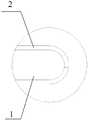
도 1은 예시적인 하나의 실시예에 따르는 모바일 기기의 정면도이다.
도 2는 예시적인 하나의 실시예에 따르는 모바일 기기의 평면도이다.
도 3은 예시적인 또 하나의 실시예에 따르는 모바일 기기의 평면도이다.
도 4는 도 3에 도시된 실시예에 따르는 모바일 기기의 A부분의 확대도이다.
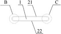
도 5는 예시적인 다른 또 하나의 실시예에 따르는 모바일 기기의 평면도이다.
도 6은 도 5에 도시된 실시예에 따르는 모바일 기기의 B부분의 확대도이다.
도 7은 예시적인 다른 또 하나의 실시예에 따르는 모바일 기기의 사시도이다.BRIEF DESCRIPTION OF THE DRAWINGS The accompanying drawings, which are incorporated in and constitute a part of the specification, illustrate embodiments of the invention and, together with the description, serve to explain the principles of the invention.
1 is a front view of a mobile device according to one exemplary embodiment.
2 is a top view of a mobile device according to one exemplary embodiment.
3 is a top view of a mobile device according to another exemplary embodiment.
4 is an enlarged view of part A of the mobile device according to the embodiment shown in Fig.
5 is a top view of a mobile device according to another exemplary embodiment.
6 is an enlarged view of part B of the mobile device according to the embodiment shown in Fig.
7 is a perspective view of a mobile device according to another exemplary embodiment.
이하, 도면을 참조하여 예시적인 실시예에 대하여 상세하게 설명하도록 한다. 이하의 설명중 도면이 언급될 시, 별도의 설명이 없는 이상, 서로 다른 도면상의 동일한 부호는 동일 또는 유사한 요소를 표시한다. 이하의 예시적 실시예에 대한 실시 형태는 본 발명과 관련되는 모든 실시 형태를 표시하는 것은 아니다. 이와 반대로, 이들은 첨부된 특허 청구의 범위에 기재되는 본 발명의 일부의 양태와 일치한 장치 및 방법의 예에 지나지 않는다.Hereinafter, exemplary embodiments will be described in detail with reference to the drawings. In the following description of the drawings, the same reference numerals denote the same or similar elements in different drawings unless otherwise described. The embodiments of the following exemplary embodiments do not denote all embodiments related to the present invention. On the contrary, they are merely examples of apparatuses and methods consistent with aspects of the present invention described in the appended claims.
도 1은 예시적인 하나의 실시예에 따르는 모바일 기기의 정면도이다. 도 1에 도시된 바와 같이, 상기 모바일 기기는,1 is a front view of a mobile device according to one exemplary embodiment. As shown in FIG. 1,
내부에, 상기 모바일 기기의 기능 부품(미도시)을 설치하기 위한 수용 공간이 형성되는 프레임 어셈블리(1)와,A
상기 프레임 어셈블리(1)의 외측에 설치되어 상기 모바일 기기의 정면, 배면 및 측면을 감싸는 메인 스크린 모듈(2)A main screen module (2) installed outside the frame assembly (1) and surrounding the front, back and sides of the mobile device,
을 포함할 수 있다.. ≪ / RTI >
본 실시예에 있어서, 프레임 어셈블리(1)는 모바일 기기의 테두리 프레임 구조 등을 포함할 수 있으며, 그 내부에 메인보드, 전원 등 기능 부품이 안착되어 외부로 부터의 충격을 회피할 수 있도록 함과 더불어, 외측의 메인 스크린 모듈(2) 등을 지지함으로써 메인 스크린 모듈(2) 및 모바일 기기 전체의 강도를 향상시킬 수 있다.In this embodiment, the
본 실시예에 있어서, 메인 스크린 모듈(2)을 이용하여 모바일 기기의 정면, 배면 및 측면을 동시에 감싸기에, 모바일 기기의 정면에만 스크린이 설치되는 종래 기술에 비하여, 메인 스크린 모듈(2) 사이즈가 모바일 기기의 정면 사이즈에 의해 제한을 받는 문제점을 타개하고 메인 스크린 모듈(2)의 표시 면적을 극대화할 수 있다. 또한, 정면, 배면 및 측면 등의 복수의 면들 사이의 협동에 의한 표시를 실시함으로써, 정면에만 의해 표시를 실시하는 종래 기술에 비하여 유저에게 참신한 시각적 효과와 유저 체험을 제공할 수 있다.The size of the
또한, 메인 스크린 모듈(2)은 다른 기타의 복수의 구조와 실현 방법을 가질 수 있다. 이하, 그 중의 몇가지 가능한 실시예에 대해 설명하도록 한다. 하지만, 본 발명이 이러한 실시예만에 한정되지 않는 것은 당연한 것이다.In addition, the
실시예 1Example 1
도 2는 예시적인 하나의 실시예에 따르는 모바일 기기의 평면도이다. 도 2에 도시된 바와 같이, 메인 스크린 모듈(2)은 일체형의 링형 구조를 가지는 스크린 모듈일 수 있다. 즉, 메인 스크린 모듈(2)은 링형 구조로써 이음매를 구비하지 않는다. 프레임 어셈블리(1) 및 그 내부의 기능 부품등을 메인 스크린 모듈(2)의 어느 하나의 단면으로 부터 삽입하여 모바일 기기의 조립을 완성한다.2 is a top view of a mobile device according to one exemplary embodiment. As shown in FIG. 2, the
본 실시예에 있어서, 메인 스크린 모듈(2)은 모바일 기기의 정면, 배면 및 측면에서 일체로 형성되어 있어, 각 면 사이에서 그 표시 내용이 완전성, 연속성을 유지할 수 있으므로, 복수면 표시의 장점을 최대한으로 발휘할 수 있어 유저의 유저 체험을 향상할 수 있다.In the present embodiment, the
실시예 2Example 2
도 3은 예시적인 또 하나의 실시예에 따르는 모바일 기기의 평면도이다. 도 3에 도시된 바와 같이, 메인 스크린 모듈(2)은 일체형의 플렉시블 평면 구조를 가지는 스크린 모듈일 수 있다. 다시 말하면, 메인 스크린 모듈(2) 그 자체는 평면 구조이지만, 상기 평면 구조를 이용하여 프레임 어셈블리(1)의 외벽 구조에 따라 프레임 어셈블리(1)의 외측을 감싸는 것을 통하여 메인 스크린 모듈(2)의 양측 끝변이 서로 연결되도록 하여 최종적으로 모바일 기기를 형성한다.3 is a top view of a mobile device according to another exemplary embodiment. As shown in FIG. 3, the
혹은, 프레임 어셈블리(1) 사이즈에 기반하여, 사전에 메인 스크린 모듈(2)을 이용하여 상기 프레임 어셈블리(1)의 형상에 정합하는 링형 구조를 형성하고 나서, 프레임 어셈블리(1) 및 그 내부의 기능 부품을 상기 링형 구조의 어느 하나의 단부로 부터 삽입하여 모바일 기기의 조립을 완성할 수 있다. 당연히 본 발명은 모바일 기기의 조립 방법에 대해 한정하지 않고, 도 1에 도시된 구조에 부합되는 모바일 기기를 얻을 수만 있다면 그 어떤 조립 방법이라도 사용할 수 있다.Alternatively, based on the size of the
도 4는 도 3에 도시된 실시예에 따르는 모바일 기기의 A부분의 확대도이다. 도 4에 도시된 바와 같이, 상기 메인 스크린 모듈(2)의 양측 끝변 사이의 이음매는 모바일 기기의 우측면에 위치하기에 면적이 제일 큰 정면과 배면에 의한 표시의 연속성을 유지할 수 있어, 이음매의 영향에 의한 위화감을 적게 할 수 있다. 당연히 이음매는 모바일 기기의 임의의 위치에 위치해도 좋으며, 예를 들어 모바일 기기의 좌측면 또는 정면, 배면 등에 위치할 수도 있으나, 본 발명은 이것들로 한정하지 않는다.4 is an enlarged view of part A of the mobile device according to the embodiment shown in Fig. As shown in FIG. 4, since the joints between the opposite ends of the
실시예 3Example 3
도 5는 예시적인 다른 또 하나의 실시예에 따르는 모바일 기기의 평면도이다. 도 5에 도시된 바와 같이, 도 1에 나타나는 메인 스크린 모듈(2)은 제1 플렉시블 스크린 모듈(21)과 제2 플렉시블 스크린 모듈(22)을 포함할 수 있다. 다시 말하면, 제1 플렉시블 스크린 모듈(21)과 제2 플렉시블 스크린 모듈(22)은 모두 평면 구조를 가지며, 메인 스크린 모듈(2)이 모바일 기기에 장착되었을 경우, 제1 플렉시블 스크린 모듈(21)과 제2 플렉시블 스크린 모듈(22)이 프레임 어셈블리(1)의 외벽 구조에 따라서 프레임 어셈블리(1)의 외측을 감싸며, 제1 플렉시블 스크린 모듈(21)과 제2 플렉시블 스크린 모듈(22) 각각의 양측 끝변끼리 서로 연결되어 최종적으로 모바일 기기를 형성한다.5 is a top view of a mobile device according to another exemplary embodiment. As shown in FIG. 5, the
혹은, 프레임 어셈블리(1)의 사이즈에 기반하여, 사전에 제1 플렉시블 스크린 모듈(21)과 제2 플렉시블 스크린 모듈(22)을 이용하여 상기 프레임 어셈블리(1)의 형상에 정합하는 링형 구조를 형성하고 나서 프레임 어셈블리(1) 및 그 내부의 기능 부품을 상기 링형 구조의 어느 하나의 단부로부터 삽입하여 모바일 기기의 조립을 완성할 수도 있다. 당연히 본 발명은 모바일 기기의 조립 방법에 대해 한정하지 않고, 도 1에 도시된 구조에 부합되는 모바일 기기를 얻을 수만 있다면 그 어떤 조립 방법이라도 사용할 수 있다.Alternatively, based on the size of the
상술한 실시예 2와 유사하게, 제1 플렉시블 스크린 모듈(21)과 제2 플렉시블 스크린 모듈(22) 사이에도 이음매가 형성되지만, 상기 이음매는 예를 들어 도 5에 도시된 B부분과 C부분에, 즉 모두 모바일 기기의 측면에 위치할 수 있다. 이것에 대응하여, 도 6에는 도 5중의 B부분의 확대도가 도시되어 있는데, 해당하는 이음매를 명확하게 관찰할 수 있다. 또한, C부분의 경우, B부분과 유사하므로 여기에서 그 설명을 생략하도록 한다.A joint is formed between the first
이음매가 모바일 기기의 측면에 위치하는 경우, 면적이 제일 큰 정면과 배면에 의한 표시의 연속성을 유지할 수 있어 이음매의 영향에 의한 위화감을 적게 할 수 있다. 당연히 이음매는 모바일 기기의 임의의 위치에 위치할 수 있다. 예를 들면, 측면 이외에도 모바일 기기의 정면, 배면 등에 위치할 수 있으나, 본 발명은 이것으로 한정하지 않는다.When the joint is located on the side surface of the mobile device, continuity of display by the front and back surfaces having the largest area can be maintained, and the discomfort due to the influence of the joint can be reduced. Naturally, the seam can be located anywhere in the mobile device. For example, it may be located on the front side or back side of the mobile device in addition to the side surface, but the present invention is not limited to this.
또한, 모바일 기기는, 상술한 어느 하나의 실시예의 구성요소 이외에도, 상기 모바일 기기의 윗측 단면 또는 아랫측 단면중의 적어도 하나에 부착되어 상기 메인 스크린 모듈(2)과 결합하여 막힘 구조를 형성하는 서브 스크린 모듈을 더 포함할 수 있다. 본 실시예에 있어서, 서브 스크린 모듈을 추가하는 것을 통하여 모바일 기기의 모든 단면을 스크린으로서 이용할 수 있어 표시 면적을 최대한으로 확대할 수 있어 올 스크린을 가지는 모바일 기기를 실현할 수 있다.In addition to the components of any one of the above-described embodiments, the mobile device may also include a sub-module attached to at least one of an upper end surface or a lower end surface of the mobile device and combined with the
예를 들어, 도 7에 도시된 바와 같이, 상기 모바일 기기는 제1 서브 스크린 모듈(31)과 제2 서브 스크린 모듈(32)을 더 포함할 수 있다. 여기서, 제1 서브 스크린 모듈(31)은 모바일 기기의 윗측 단면에서 메인 스크린 모듈(2)과 결합하여 제1 막힘 구조를 형성하고, 제2 서브 스크린 모듈(32)은 모바일 기기의 아랫측 단면에서 메인 스크린 모듈(2)과 결합하여 제2 막힘 구조를 형성한다.For example, as shown in FIG. 7, the mobile device may further include a first
당업자는 명세서를 참조하고 또한 여기에 공개된 발명을 실행한 후, 본 발명의 기타 실시방안을 용이하게 생각해낼 수 있다. 본 출원은, 본 발명의 임의의 변형, 용도 또는 적응적인 변화를 포함하고, 이러한 변형, 용도 또는 적응적인 변화는 본 발명의 일반적인 원리에 따르며 본 명세서에서 공개하지 않은 본 기술분야의 공지상식 또는 관용 기술수단을 포함한다. 명세서와 실시예는 단지 예시적인 것으로서, 본 발명의 진정한 범위 및 취지는 첨부된 특허 청구 범위에 의하여 한정된다.Those skilled in the art will readily conceive of other implementations of the invention after referring to the specification and implementing the invention disclosed herein. This application is intended to cover any variations, uses, or adaptations of the invention, and such modifications, uses, or adaptations may be made without departing from the spirit and scope of the present general inventive concept, Technical means. It is intended that the specification and examples be considered as exemplary only, with a true scope and spirit of the invention being indicated by the appended claims.
본 발명은, 위에서 설명되고 또한 도면에 의해 구현된 정확한 구조에 한정되지 않으며, 그 범위를 이탈하지 않는 한 다양한 변형 및 수정을 실시할 수 있다는 것을 이해하여야 한다. 본 발명의 범위는 첨부된 특허 청구 범위에 의해서만 한정된다.It is to be understood that the present invention is not limited to the precise structure described above and embodied by the drawings, and that various modifications and changes may be made thereto without departing from the scope thereof. The scope of the invention is limited only by the appended claims.
Claims (7)
Translated fromKorean내부에 상기 모바일 기기의 기능 부품을 설치하기 위한 수용 공간이 형성되는 프레임 어셈블리와,
상기 프레임 어셈블리의 외측에 설치되어 상기 모바일 기기의 정면, 배면, 좌측면 및 우측면을 감싸는 메인 스크린 모듈과,
상기 모바일 기기의 윗측 단면에서 상기 메인 스크린 모듈과 결합하여 제1 막힘 구조를 형성하는 제1 서브 스크린 모듈과,
상기 모바일 기기의 아랫측 단면에서 상기 메인 스크린 모듈과 결합하여 제2 막힘 구조를 형성하는 제2 서브 스크린 모듈
을 포함하는 것을 특징으로 하는
모바일 기기.
In a mobile device,
A frame assembly in which a receiving space for installing functional components of the mobile device is formed,
A main screen module installed on the outer side of the frame assembly and enclosing a front surface, a rear surface, a left surface and a right surface of the mobile device,
A first sub screen module coupled to the main screen module at an upper end surface of the mobile device to form a first screen structure;
And a second sub-screen module coupled to the main screen module at a lower end section of the mobile device to form a second clogging structure,
≪ RTI ID = 0.0 >
Mobile devices.
상기 메인 스크린 모듈은 일체형의 링형 구조를 가지는 스크린 모듈인 것을 특징으로 하는
모바일 기기.
The method according to claim 1,
Wherein the main screen module is a screen module having a ring-shaped structure
Mobile devices.
상기 메인 스크린 모듈은 일체형의 플렉시블 평면 구조를 가지는 스크린 모듈이며,
상기 스크린 모듈이 상기 모바일 기기에 장착되었을 경우, 상기 메인 스크린 모듈의 양측 끝변이 서로 연결되어 링형 구조를 형성하는 것을 특징으로 하는
모바일 기기.
The method according to claim 1,
Wherein the main screen module is a screen module having an integral flexible flat structure,
When the screen module is mounted on the mobile device, both side ends of the main screen module are connected to each other to form a ring-like structure.
Mobile devices.
상기 메인 스크린 모듈이 상기 모바일 기기에 장착되었을 경우, 형성된 링형 구조의 이음매는 상기 모바일 기기의 어느 하나의 측면에 위치하는 것을 특징으로 하는
모바일 기기.
The method of claim 3,
When the main screen module is mounted on the mobile device, the joint of the ring-shaped structure formed is located on one side of the mobile device
Mobile devices.
상기 메인 스크린 모듈은 제1 플렉시블 스크린 모듈과 제2 플렉시블 스크린 모듈을 포함하고,
상기 메인 스크린 모듈이 상기 모바일 기기에 장착되었을 경우, 상기 제1 플렉시블 스크린 모듈과 상기 제2 플렉시블 스크린 모듈 각각의 양측 끝변끼리 서로 연결되어 링형 구조를 형성하는 것을 특징으로 하는
모바일 기기.
The method according to claim 1,
Wherein the main screen module comprises a first flexible screen module and a second flexible screen module,
Wherein when the main screen module is mounted on the mobile device, both the first and second flexible screen modules and the second flexible screen module are connected to each other to form a ring structure.
Mobile devices.
상기 메인 스크린 모듈이 상기 모바일 기기에 장착되었을 경우, 상기 제1 플렉시블 스크린 모듈과 상기 제2 플렉시블 스크린 모듈 사이의 이음매는 각각 상기 모바일 기기의 2개의 측면에 위치하는 것을 특징으로 하는
모바일 기기.
6. The method of claim 5,
Wherein the joints between the first flexible screen module and the second flexible screen module are respectively located on two sides of the mobile device when the main screen module is mounted on the mobile device
Mobile devices.
Applications Claiming Priority (3)
| Application Number | Priority Date | Filing Date | Title |
|---|---|---|---|
| CN201510359811.5ACN106325367B (en) | 2015-06-25 | 2015-06-25 | Mobile device |
| CN201510359811.5 | 2015-06-25 | ||
| PCT/CN2015/090295WO2016206200A1 (en) | 2015-06-25 | 2015-09-22 | Mobile device |
Publications (2)
| Publication Number | Publication Date |
|---|---|
| KR20170011973A KR20170011973A (en) | 2017-02-02 |
| KR101992518B1true KR101992518B1 (en) | 2019-06-24 |
Family
ID=56615812
Family Applications (1)
| Application Number | Title | Priority Date | Filing Date |
|---|---|---|---|
| KR1020157033026AActiveKR101992518B1 (en) | 2015-06-25 | 2015-09-22 | Mobile device |
Country Status (8)
| Country | Link |
|---|---|
| US (1) | US9838518B2 (en) |
| EP (2) | EP3116203A1 (en) |
| JP (1) | JP6411654B2 (en) |
| KR (1) | KR101992518B1 (en) |
| CN (1) | CN106325367B (en) |
| MX (1) | MX355964B (en) |
| RU (1) | RU2649798C2 (en) |
| WO (1) | WO2016206200A1 (en) |
Cited By (1)
| Publication number | Priority date | Publication date | Assignee | Title |
|---|---|---|---|---|
| KR20210064101A (en)* | 2019-11-22 | 2021-06-02 | 베이징 시아오미 모바일 소프트웨어 컴퍼니 리미티드 | Flexible screen module, terminal device and shooting method |
Families Citing this family (33)
| Publication number | Priority date | Publication date | Assignee | Title |
|---|---|---|---|---|
| USD779449S1 (en)* | 2014-10-01 | 2017-02-21 | Samsung Electronics Co., Ltd. | Portable electronic device |
| USD820801S1 (en)* | 2015-11-04 | 2018-06-19 | Lenovo (Beijing) Co., Ltd. | Flexible electronic device |
| USD783567S1 (en) | 2016-04-14 | 2017-04-11 | Samsung Electronics Co., Ltd. | Mobile phone |
| USD791112S1 (en)* | 2016-04-14 | 2017-07-04 | Samsung Electronics Co., Ltd. | Mobile phone |
| KR102456540B1 (en)* | 2016-05-02 | 2022-10-20 | 삼성전자주식회사 | Electronic device having enclosed window and manufacturing method thereof |
| KR102660537B1 (en) | 2016-07-19 | 2024-04-26 | 삼성디스플레이 주식회사 | Display apparatus |
| KR102592054B1 (en)* | 2016-12-23 | 2023-10-23 | 삼성전자주식회사 | electronic device including glass housing |
| CN108667960B (en)* | 2017-03-30 | 2020-09-22 | 昆山国显光电有限公司 | Mobile electronic display product |
| USD848993S1 (en)* | 2017-06-01 | 2019-05-21 | Samsung Electronics Co., Ltd. | Mobile phone |
| CN107770343A (en)* | 2017-09-29 | 2018-03-06 | 努比亚技术有限公司 | A kind of mobile terminal case structure and mobile terminal |
| CN107682481A (en)* | 2017-09-29 | 2018-02-09 | 努比亚技术有限公司 | A kind of mobile terminal screen structure and mobile terminal |
| CN108200244A (en)* | 2017-12-28 | 2018-06-22 | 广东欧珀移动通信有限公司 | Electronic device |
| DE102018205616A1 (en) | 2018-04-13 | 2019-10-17 | Audi Ag | Portable, mobile operating device in which a display area is provided on at least two surface areas |
| CN110392134B (en)* | 2018-04-20 | 2021-07-27 | Oppo广东移动通信有限公司 | A display screen assembly and electronic equipment |
| CN110392136B (en)* | 2018-04-20 | 2021-06-01 | Oppo广东移动通信有限公司 | Mobile terminal, display control method thereof, and computer storage medium |
| CN110392138B (en)* | 2018-04-20 | 2021-06-01 | Oppo广东移动通信有限公司 | An electronic device and its assembly method |
| CN110401735A (en)* | 2018-04-24 | 2019-11-01 | Oppo广东移动通信有限公司 | Electronic equipment |
| CN110401742A (en)* | 2018-04-25 | 2019-11-01 | Oppo广东移动通信有限公司 | Electronic equipment and curved surface display screen thereof |
| CN110417939B (en)* | 2018-04-26 | 2021-03-30 | Oppo广东移动通信有限公司 | Electronic device |
| CN110417938B (en)* | 2018-04-26 | 2021-06-01 | Oppo广东移动通信有限公司 | electronic device |
| CN110445899B (en)* | 2018-05-04 | 2021-06-01 | Oppo广东移动通信有限公司 | An electronic device, control method thereof, and computer storage medium |
| CN108924284B (en)* | 2018-06-08 | 2021-04-09 | Oppo广东移动通信有限公司 | Electronic device and control method and device of sliding assembly of electronic device |
| CN108848216A (en)* | 2018-06-25 | 2018-11-20 | 维沃移动通信有限公司 | A kind of mobile terminal |
| CN108989505A (en)* | 2018-08-01 | 2018-12-11 | 上海天马有机发光显示技术有限公司 | Display device and its display device preparation method |
| JP1653373S (en)* | 2019-07-11 | 2020-02-25 | Mobile phone | |
| CN110459137A (en)* | 2019-07-31 | 2019-11-15 | 广东长盈精密技术有限公司 | Electronic equipment and display screen thereof |
| CN110794923B (en)* | 2019-10-21 | 2021-04-13 | 维沃移动通信有限公司 | Display module, control method and device thereof and electronic equipment |
| US11321545B2 (en)* | 2020-06-30 | 2022-05-03 | Datalogic IP Tech, S.r.l. | Barcode scanner system with animated feedback |
| CN111785177A (en)* | 2020-08-17 | 2020-10-16 | 京东方科技集团股份有限公司 | A flexible display module and flexible display device |
| CN112037652A (en)* | 2020-08-20 | 2020-12-04 | 武汉华星光电半导体显示技术有限公司 | Display screen, manufacturing method of display screen and electronic equipment |
| CN115311939B (en)* | 2021-05-08 | 2024-09-03 | 北京小米移动软件有限公司 | Electronic equipment, display screen assembly and production process of display screen assembly |
| USD1081639S1 (en) | 2023-02-15 | 2025-07-01 | Alo Beauty Corp | Portable electronic device case |
| USD1081638S1 (en) | 2023-02-15 | 2025-07-01 | Alo Beauty Corp | Portable electronic device case with attachable display module |
Citations (1)
| Publication number | Priority date | Publication date | Assignee | Title |
|---|---|---|---|---|
| US20110261002A1 (en)* | 2010-04-27 | 2011-10-27 | Microsoft Corporation | Displaying images on solid surfaces |
Family Cites Families (33)
| Publication number | Priority date | Publication date | Assignee | Title |
|---|---|---|---|---|
| US6125286A (en)* | 1997-06-05 | 2000-09-26 | Motorola, Inc. | Communication device having multiple displays and method of operating the same |
| JP2002328625A (en)* | 2001-04-27 | 2002-11-15 | Pioneer Electronic Corp | Display device |
| JP2003076274A (en)* | 2001-09-07 | 2003-03-14 | Kineshio:Kk | Variable display sheet |
| CN2523132Y (en)* | 2001-11-28 | 2002-11-27 | 潘杰 | New-type double-screen-display mobile phone set |
| US20090225509A1 (en)* | 2007-05-01 | 2009-09-10 | Daley Iii Charles A | Bag computer two part display panel |
| CN101567916A (en)* | 2008-04-24 | 2009-10-28 | 鸿富锦精密工业(深圳)有限公司 | Portable electronic device |
| KR101521219B1 (en)* | 2008-11-10 | 2015-05-18 | 엘지전자 주식회사 | Mobile terminal using flexible display and operation method thereof |
| US8195244B2 (en)* | 2009-02-25 | 2012-06-05 | Centurylink Intellectual Property Llc | Multi-directional display communication devices, systems, and methods |
| US8890771B2 (en)* | 2010-01-06 | 2014-11-18 | Apple Inc. | Transparent electronic device |
| CN201628881U (en)* | 2010-01-25 | 2010-11-10 | 张菊 | Double-screen display equipment |
| GB201112458D0 (en)* | 2010-09-28 | 2011-08-31 | Yota Group Cyprus Ltd | device with display screen |
| CN103370924A (en)* | 2010-12-10 | 2013-10-23 | 尤塔设备Ipr有限公司 | Mobile device with user interface |
| CN102004614B (en)* | 2010-12-30 | 2013-06-19 | Tcl集团股份有限公司 | Dual-screen touch sensible display electronic device and realization method thereof |
| TWI411843B (en)* | 2010-12-30 | 2013-10-11 | Au Optronics Corp | Display |
| US9178970B2 (en)* | 2011-03-21 | 2015-11-03 | Apple Inc. | Electronic devices with convex displays |
| CN102209128B (en)* | 2011-05-04 | 2015-05-13 | 候万春 | Four-sided touch screen mobile phone terminal |
| US9176535B2 (en)* | 2011-06-03 | 2015-11-03 | Microsoft Technology Licensing, Llc | Flexible display flexure assembly |
| US8665236B2 (en)* | 2011-09-26 | 2014-03-04 | Apple Inc. | Electronic device with wrap around display |
| KR101515629B1 (en)* | 2012-01-07 | 2015-04-27 | 삼성전자주식회사 | Method and apparatus for providing event of portable device having flexible display unit |
| KR101929812B1 (en)* | 2012-01-30 | 2018-12-17 | 엘지전자 주식회사 | Mobile terminal and method for fabricating the same |
| US9429997B2 (en)* | 2012-06-12 | 2016-08-30 | Apple Inc. | Electronic device with wrapped display |
| CN202677020U (en)* | 2012-06-29 | 2013-01-16 | 天马微电子股份有限公司 | Touch display device |
| CA2818506A1 (en) | 2012-07-03 | 2014-01-03 | Tomoe Engineering Co., Ltd. | Sludge processing system and storage medium storing a program for controlling an operation of a sludge processing system thereon |
| KR101940104B1 (en)* | 2012-08-24 | 2019-01-21 | 삼성디스플레이 주식회사 | Flexible display device having slap portion |
| CN102933054B (en)* | 2012-11-02 | 2015-06-17 | 京东方科技集团股份有限公司 | Fixing frame component for display module group and display module group |
| KR20140094930A (en)* | 2013-01-23 | 2014-07-31 | 엘지전자 주식회사 | Mobile terminal |
| CN103116229B (en)* | 2013-02-04 | 2015-08-12 | 小米科技有限责任公司 | A kind of containment vessel and liquid crystal display terminal |
| KR20250002802A (en)* | 2013-11-29 | 2025-01-07 | 가부시키가이샤 한도오따이 에네루기 켄큐쇼 | Data processing device and driving method thereof |
| CN204028876U (en)* | 2014-06-30 | 2014-12-17 | 比亚迪股份有限公司 | A kind of touch-screen module and mobile terminal |
| CN104181716A (en)* | 2014-08-22 | 2014-12-03 | 深圳市中兴移动通信有限公司 | Frameless display unit |
| CN104460089B (en)* | 2014-12-12 | 2018-02-16 | 京东方科技集团股份有限公司 | A kind of Multiside displaying device part |
| CN104461160A (en)* | 2014-12-31 | 2015-03-25 | 业成光电(深圳)有限公司 | Touch display device |
| CN205620851U (en)* | 2015-06-25 | 2016-10-05 | 小米科技有限责任公司 | Mobile equipment |
- 2015
- 2015-06-25CNCN201510359811.5Apatent/CN106325367B/enactiveActive
- 2015-09-22WOPCT/CN2015/090295patent/WO2016206200A1/ennot_activeCeased
- 2015-09-22MXMX2015016618Apatent/MX355964B/enactiveIP Right Grant
- 2015-09-22JPJP2017524086Apatent/JP6411654B2/enactiveActive
- 2015-09-22KRKR1020157033026Apatent/KR101992518B1/enactiveActive
- 2015-09-22RURU2015150720Apatent/RU2649798C2/enactive
- 2016
- 2016-02-29USUS15/056,405patent/US9838518B2/enactiveActive
- 2016-06-13EPEP16174247.3Apatent/EP3116203A1/ennot_activeCeased
- 2016-06-13EPEP22169591.9Apatent/EP4050872A1/enactivePending
Patent Citations (1)
| Publication number | Priority date | Publication date | Assignee | Title |
|---|---|---|---|---|
| US20110261002A1 (en)* | 2010-04-27 | 2011-10-27 | Microsoft Corporation | Displaying images on solid surfaces |
Cited By (3)
| Publication number | Priority date | Publication date | Assignee | Title |
|---|---|---|---|---|
| KR20210064101A (en)* | 2019-11-22 | 2021-06-02 | 베이징 시아오미 모바일 소프트웨어 컴퍼니 리미티드 | Flexible screen module, terminal device and shooting method |
| KR102338914B1 (en)* | 2019-11-22 | 2021-12-10 | 베이징 시아오미 모바일 소프트웨어 컴퍼니 리미티드 | Flexible screen module, terminal device and shooting method |
| US11588962B2 (en) | 2019-11-22 | 2023-02-21 | Beijing Xiaomi Mobile Software Co., Ltd. | Flexible screen module, terminal device and photographing method |
Also Published As
| Publication number | Publication date |
|---|---|
| JP2017524318A (en) | 2017-08-24 |
| CN106325367B (en) | 2023-08-04 |
| RU2015150720A (en) | 2017-06-20 |
| US20160381194A1 (en) | 2016-12-29 |
| EP4050872A1 (en) | 2022-08-31 |
| EP3116203A1 (en) | 2017-01-11 |
| MX355964B (en) | 2018-05-04 |
| MX2015016618A (en) | 2017-02-23 |
| US9838518B2 (en) | 2017-12-05 |
| RU2649798C2 (en) | 2018-04-04 |
| JP6411654B2 (en) | 2018-10-24 |
| KR20170011973A (en) | 2017-02-02 |
| WO2016206200A1 (en) | 2016-12-29 |
| CN106325367A (en) | 2017-01-11 |
Similar Documents
| Publication | Publication Date | Title |
|---|---|---|
| KR101992518B1 (en) | Mobile device | |
| ZA202209786B (en) | Foldable electronic device including hinge assembly | |
| US20160139627A1 (en) | Supporting plate, touch display panel and touch display device | |
| TWI539832B (en) | Portable electronic device | |
| JP6220900B2 (en) | mobile computer | |
| EP2713585B1 (en) | Electronic apparatus and method for assembling the same | |
| JP4191794B2 (en) | Portable electronic devices | |
| JP2016092382A (en) | Heat dissipation module | |
| KR20140144405A (en) | Shield can assembly and electronic device having it | |
| CN205620851U (en) | Mobile equipment | |
| EP2571231A1 (en) | Cushion for a folding handheld electronic device and waterproofing structure for a folding handheld electronic device | |
| JP3194097U (en) | Case assembly | |
| US9282668B2 (en) | Electronic apparatus and method for assembling the same | |
| JP5002713B1 (en) | Electronics | |
| US8466377B2 (en) | Electronic device housing | |
| CN110278673B (en) | Electronic device | |
| CN203746722U (en) | Support panel integrated with button | |
| JP2015215683A (en) | Portable electronic apparatus and fingerprint sensor unit | |
| JP2013064990A (en) | Display device and television apparatus | |
| CN105451528A (en) | Shielding device | |
| CN108429827B (en) | Electronic components and electronic equipment | |
| JP2005311005A (en) | Structure for joining and member for joining printed board to hinge unit in folding type mobile terminal | |
| KR102188111B1 (en) | Unit fixing device and electronic device having it | |
| JP6115954B2 (en) | Communication equipment | |
| TW201702791A (en) | Electrical device |
Legal Events
| Date | Code | Title | Description |
|---|---|---|---|
| A201 | Request for examination | ||
| AMND | Amendment | ||
| PA0105 | International application | Patent event date:20151119 Patent event code:PA01051R01D Comment text:International Patent Application | |
| PA0201 | Request for examination | ||
| PE0902 | Notice of grounds for rejection | Comment text:Notification of reason for refusal Patent event date:20160823 Patent event code:PE09021S01D | |
| PG1501 | Laying open of application | ||
| PE0601 | Decision on rejection of patent | Patent event date:20170228 Comment text:Decision to Refuse Application Patent event code:PE06012S01D Patent event date:20160823 Comment text:Notification of reason for refusal Patent event code:PE06011S01I | |
| PX0901 | Re-examination | Patent event code:PX09011S01I Patent event date:20170228 Comment text:Decision to Refuse Application Patent event code:PX09012R01I Patent event date:20151119 Comment text:Amendment to Specification, etc. | |
| E902 | Notification of reason for refusal | ||
| PE0902 | Notice of grounds for rejection | Comment text:Notification of reason for refusal Patent event date:20170427 Patent event code:PE09021S01D | |
| PX0601 | Decision of rejection after re-examination | Comment text:Decision to Refuse Application Patent event code:PX06014S01D Patent event date:20171031 Comment text:Amendment to Specification, etc. Patent event code:PX06012R01I Patent event date:20170622 Comment text:Notification of reason for refusal Patent event code:PX06013S01I Patent event date:20170427 Comment text:Amendment to Specification, etc. Patent event code:PX06012R01I Patent event date:20170403 Comment text:Decision to Refuse Application Patent event code:PX06011S01I Patent event date:20170228 Comment text:Notification of reason for refusal Patent event code:PX06013S01I Patent event date:20160823 Comment text:Amendment to Specification, etc. Patent event code:PX06012R01I Patent event date:20151119 | |
| J201 | Request for trial against refusal decision | ||
| PJ0201 | Trial against decision of rejection | Patent event date:20171201 Comment text:Request for Trial against Decision on Refusal Patent event code:PJ02012R01D Patent event date:20171031 Comment text:Decision to Refuse Application Patent event code:PJ02011S01I Patent event date:20170228 Comment text:Decision to Refuse Application Patent event code:PJ02011S01I Appeal kind category:Appeal against decision to decline refusal Decision date:20190508 Appeal identifier:2017101005819 Request date:20171201 | |
| J301 | Trial decision | Free format text:TRIAL NUMBER: 2017101005819; TRIAL DECISION FOR APPEAL AGAINST DECISION TO DECLINE REFUSAL REQUESTED 20171201 Effective date:20190508 | |
| PJ1301 | Trial decision | Patent event code:PJ13011S01D Patent event date:20190508 Comment text:Trial Decision on Objection to Decision on Refusal Appeal kind category:Appeal against decision to decline refusal Request date:20171201 Decision date:20190508 Appeal identifier:2017101005819 | |
| PS0901 | Examination by remand of revocation | ||
| S901 | Examination by remand of revocation | ||
| GRNO | Decision to grant (after opposition) | ||
| PS0701 | Decision of registration after remand of revocation | Patent event date:20190528 Patent event code:PS07012S01D Comment text:Decision to Grant Registration Patent event date:20190508 Patent event code:PS07011S01I Comment text:Notice of Trial Decision (Remand of Revocation) | |
| GRNT | Written decision to grant | ||
| PR0701 | Registration of establishment | Comment text:Registration of Establishment Patent event date:20190618 Patent event code:PR07011E01D | |
| PR1002 | Payment of registration fee | Payment date:20190618 End annual number:3 Start annual number:1 | |
| PG1601 | Publication of registration | ||
| PR1001 | Payment of annual fee | Payment date:20220610 Start annual number:4 End annual number:4 | |
| PR1001 | Payment of annual fee | Payment date:20250609 Start annual number:7 End annual number:7 |