KR101989823B1 - Apparatus for fixing a cervical spine - Google Patents
Apparatus for fixing a cervical spineDownload PDFInfo
- Publication number
- KR101989823B1 KR101989823B1KR1020170100466AKR20170100466AKR101989823B1KR 101989823 B1KR101989823 B1KR 101989823B1KR 1020170100466 AKR1020170100466 AKR 1020170100466AKR 20170100466 AKR20170100466 AKR 20170100466AKR 101989823 B1KR101989823 B1KR 101989823B1
- Authority
- KR
- South Korea
- Prior art keywords
- plate
- screw
- rotation
- screw insertion
- insertion hole
- Prior art date
- Legal status (The legal status is an assumption and is not a legal conclusion. Google has not performed a legal analysis and makes no representation as to the accuracy of the status listed.)
- Active
Links
Images


Classifications
- A—HUMAN NECESSITIES
- A61—MEDICAL OR VETERINARY SCIENCE; HYGIENE
- A61B—DIAGNOSIS; SURGERY; IDENTIFICATION
- A61B17/00—Surgical instruments, devices or methods
- A61B17/56—Surgical instruments or methods for treatment of bones or joints; Devices specially adapted therefor
- A61B17/58—Surgical instruments or methods for treatment of bones or joints; Devices specially adapted therefor for osteosynthesis, e.g. bone plates, screws or setting implements
- A61B17/68—Internal fixation devices, including fasteners and spinal fixators, even if a part thereof projects from the skin
- A61B17/84—Fasteners therefor or fasteners being internal fixation devices
- A61B17/86—Pins or screws or threaded wires; nuts therefor
- A—HUMAN NECESSITIES
- A61—MEDICAL OR VETERINARY SCIENCE; HYGIENE
- A61B—DIAGNOSIS; SURGERY; IDENTIFICATION
- A61B17/00—Surgical instruments, devices or methods
- A61B17/56—Surgical instruments or methods for treatment of bones or joints; Devices specially adapted therefor
- A61B17/58—Surgical instruments or methods for treatment of bones or joints; Devices specially adapted therefor for osteosynthesis, e.g. bone plates, screws or setting implements
- A61B17/68—Internal fixation devices, including fasteners and spinal fixators, even if a part thereof projects from the skin
- A61B17/70—Spinal positioners or stabilisers, e.g. stabilisers comprising fluid filler in an implant
- A61B17/7059—Cortical plates
- A—HUMAN NECESSITIES
- A61—MEDICAL OR VETERINARY SCIENCE; HYGIENE
- A61B—DIAGNOSIS; SURGERY; IDENTIFICATION
- A61B17/00—Surgical instruments, devices or methods
- A61B17/56—Surgical instruments or methods for treatment of bones or joints; Devices specially adapted therefor
- A61B17/58—Surgical instruments or methods for treatment of bones or joints; Devices specially adapted therefor for osteosynthesis, e.g. bone plates, screws or setting implements
- A61B17/68—Internal fixation devices, including fasteners and spinal fixators, even if a part thereof projects from the skin
- A61B17/80—Cortical plates, i.e. bone plates; Instruments for holding or positioning cortical plates, or for compressing bones attached to cortical plates
- A61B17/8033—Cortical plates, i.e. bone plates; Instruments for holding or positioning cortical plates, or for compressing bones attached to cortical plates having indirect contact with screw heads, or having contact with screw heads maintained with the aid of additional components, e.g. nuts, wedges or head covers
- A61B17/8042—Cortical plates, i.e. bone plates; Instruments for holding or positioning cortical plates, or for compressing bones attached to cortical plates having indirect contact with screw heads, or having contact with screw heads maintained with the aid of additional components, e.g. nuts, wedges or head covers the additional component being a cover over the screw head
- A—HUMAN NECESSITIES
- A61—MEDICAL OR VETERINARY SCIENCE; HYGIENE
- A61B—DIAGNOSIS; SURGERY; IDENTIFICATION
- A61B17/00—Surgical instruments, devices or methods
- A61B17/56—Surgical instruments or methods for treatment of bones or joints; Devices specially adapted therefor
- A61B17/58—Surgical instruments or methods for treatment of bones or joints; Devices specially adapted therefor for osteosynthesis, e.g. bone plates, screws or setting implements
- A61B17/68—Internal fixation devices, including fasteners and spinal fixators, even if a part thereof projects from the skin
- A61B17/80—Cortical plates, i.e. bone plates; Instruments for holding or positioning cortical plates, or for compressing bones attached to cortical plates
- A61B17/8052—Cortical plates, i.e. bone plates; Instruments for holding or positioning cortical plates, or for compressing bones attached to cortical plates immobilised relative to screws by interlocking form of the heads and plate holes, e.g. conical or threaded
- A—HUMAN NECESSITIES
- A61—MEDICAL OR VETERINARY SCIENCE; HYGIENE
- A61B—DIAGNOSIS; SURGERY; IDENTIFICATION
- A61B17/00—Surgical instruments, devices or methods
- A61B17/56—Surgical instruments or methods for treatment of bones or joints; Devices specially adapted therefor
- A61B17/58—Surgical instruments or methods for treatment of bones or joints; Devices specially adapted therefor for osteosynthesis, e.g. bone plates, screws or setting implements
- A61B17/68—Internal fixation devices, including fasteners and spinal fixators, even if a part thereof projects from the skin
- A61B17/84—Fasteners therefor or fasteners being internal fixation devices
- A61B17/86—Pins or screws or threaded wires; nuts therefor
- A61B2017/8655—Pins or screws or threaded wires; nuts therefor with special features for locking in the bone
Landscapes
- Health & Medical Sciences (AREA)
- Orthopedic Medicine & Surgery (AREA)
- Life Sciences & Earth Sciences (AREA)
- Surgery (AREA)
- Neurology (AREA)
- Heart & Thoracic Surgery (AREA)
- Engineering & Computer Science (AREA)
- Biomedical Technology (AREA)
- Nuclear Medicine, Radiotherapy & Molecular Imaging (AREA)
- Medical Informatics (AREA)
- Molecular Biology (AREA)
- Animal Behavior & Ethology (AREA)
- General Health & Medical Sciences (AREA)
- Public Health (AREA)
- Veterinary Medicine (AREA)
- Surgical Instruments (AREA)
Abstract
Translated fromKoreanDescription
Translated fromKorean본 발명은 정형외과 또는 신경외과에서 경추 전방 고정수술시 사용되는 경추고정장치에 관한 것으로서, 보다 상세하게는, 플레이트의 나사 삽입홀에 삽입된 뼈나사를 회전가능한 잠금부로 용이하게 고정시키는 경추고정장치에 관한 것이다.BACKGROUND OF THE
일반적으로, 정형외과 또는 신경외과에서 경추 추간판 질환, 경추 디스크, 경추성 척수증, 경추 골절 등의 치료시 각각의 경추를 상호 고정시켜 움직임이 없도록 고정시켜야 하며, 이를 위하여 판 형상의 플레이트와 플레이트를 경추에 고정시키는 나사로 이루어진 경추고정장치가 사용된다.In general, orthopedic surgery or neurosurgery should fix the cervical vertebrae to prevent movement during cervical disc disease, cervical disc, cervical spondylosis, and cervical vertebral fracture. For this purpose, A cervical spine fixation device is used.
이러한 경추고정장치의 시술은 환자의 목 부분의 전방으로부터 환부를 절개하고 경추를 노출시켜 경추용 케이지 등의 시술물을 경추증 환부에 시술한 다음, 플레이트를 환부 상단과 하단에 위치시키고 나사에 의하여 해당 플레이트를 고정하는 방식으로 이루어진다.The procedure of the cervical fixation device is performed by incising the affected part from the front of the neck part of the patient and exposing the cervical vertebrae to the cervical vertebra cage or the like and then placing the plate on the upper and lower ends of the lesion, And the plate is fixed.
그러면, 경추고정장치의 나사의 고정력과 플레이트의 지지력에 의하여 경추에 시술된 케이지 등의 시술물이 움직이지 않도록 고정되게 된다.Then, according to the fixation force of the screw of the cervical spine fixation device and the support force of the plate, the treatment article such as the cage or the like, which is performed on the cervical vertebra, is fixed so as not to move.
그런데, 시술후 환자의 활동 등에 의하여 나사가 경추고정장치의 플레이트에서 풀려져 나오면서 플레이트로부터 후퇴되는 현상이 발생될 수 있다. 이러한 현상을 방지하기 위한 종래기술 중 한국등록특허 제10-0552117호(경추고정장치 및 이에 사용되는 드라이버)와 미국공개특허 US 2016-0095637호(LOCKING MECHANISM FOR A CERVICAL FIXATION PLATE)가 알려져 있다.However, due to the patient's activity after the procedure, the screw may be pulled out of the plate of the cervical spine fixture and retracted from the plate. Korean Patent No. 10-0552117 (a cervical spine fixation device and a driver used therein) and US Patent Publication No. US 2016-0095637 (LOCKING MECHANISM FOR A CERVICAL FIXATION PLATE) are known from the prior art to prevent such a phenomenon.
내용을 살펴보면, 한국등록특허 제10-0552117호는 플레이트에 형성된 개구부에 스크류를 삽입하고 고정부재를 리셋부에 안착시킴으로써 스크류의 이탈을 방지하고 있으며, 미국공개특허 US 2016-0095637호는 Plate body에 형성된 Bone screw opening에 Bone screw를 삽입하고 Locking element를 Rocking post에 체결함으로써 Screw의 이탈을 방지하고 있다.Korean Patent No. 10-0552117 discloses that a screw is inserted into an opening formed in a plate and a fixing member is seated on a reset portion to prevent the screw from being released. US Patent Application Publication No. US 2016-0095637 discloses a plate body Bone screw is inserted into the formed screw opening and the locking element is fastened to the locking post to prevent the screw from escaping.
그러나, 한국등록특허 제10-0552117호에서는 고정부재를 안착시키기 위해 플레이트에 리벳결합을 해야하는 번거로운 문제점이 있으며, 미국공개특허 US 2016-0095637호에서는 환자의 움직임으로 인해 Plate body 외부로 돌출된 Locking element가 다른 물건에 걸려 파손될 수 있는 점, Plate body에 Rocking post를 별도로 가공해야 하는 문제점 등이 있다.However, in Korean Patent No. 10-0552117, there is a troublesome problem that a rivet is required to be attached to a plate in order to seat the fixing member. US Patent Publication No. US 2016-0095637 discloses a locking member protruding from the plate body Can be damaged by other objects, and there is a problem that a rocking post needs to be processed separately in the plate body.
본 발명은 상술한 바와 같은 종래기술의 문제점을 해결하기 위한 것으로서, 뼈나사의 인출을 방지하는 잠금부가 단차부에 안착됨으로써 환자의 활동에 불구하고 잠금부가 플레이트에서 빠지거나 걸림파손될 염려가 없고, 시술자가 잠금부의 회전을 통해 간단하게 뼈나사의 인출을 방지할 수 있는 경추고정장치를 제시하고자 한다.SUMMARY OF THE INVENTION The present invention has been made in order to solve the problems of the prior art as described above, and it is an object of the present invention to provide a bone grafting device, A cervical spine fixation device capable of preventing the withdrawal of a bone screw simply by rotating the locking part.
본 발명은, 복수의 나사 삽입홀이 형성된 판넬 형태의 플레이트; 상기 나사 삽입홀에 삽입되어 회전을 통해 골편과 나사결합되는 뼈 나사; 및 상기 플레이트에 회전가능하게 결합되어 상기 나사 삽입홀의 상면을 개폐하는 잠금부;를 포함하고,상기 플레이트의 상면에는 일정 깊이의 단차부가 형성되고, 상기 단차부는 상기 잠금부의 회전이 가능한 회전영역이 마련되며, 상기 회전영역에는 상기 잠금부가 삽입되도록 잠금부 삽입홀이 형성되는 경추고정장치를 제공한다.The present invention relates to a plate type plate having a plurality of screw insertion holes formed therein; A bone screw inserted into the screw insertion hole and screwed to the bone piece through rotation; And a lock portion rotatably coupled to the plate to open and close an upper surface of the screw insertion hole, wherein a stepped portion having a predetermined depth is formed on an upper surface of the plate, and the step portion has a rotation region in which the lock portion is rotatable And a locking portion insertion hole is formed in the rotation region so that the locking portion is inserted into the locking portion insertion hole.
상기 잠금부는, 상기 잠금부 삽입홀에 삽입되는 수직부; 상기 수직부와 일체로 결합하여 상기 회전영역에 면접하는 수평부; 및 상기 수평부에 형성되어 상기 회전영역에 인접하는 2개의 나사 삽입홀의 상면을 동시에 개폐하는 복수의 고정날개;를 포함한다.The locking portion may include: a vertical portion inserted into the locking portion insertion hole; A horizontal portion which is integrally combined with the vertical portion and is in contact with the rotation region; And a plurality of fixed vanes formed on the horizontal portion and simultaneously opening and closing upper surfaces of two screw insertion holes adjacent to the rotation region.
상기 복수의 고정날개 사이의 각도는 120°인 것을 특징으로 한다.And an angle between the plurality of fixed wings is 120 °.
상기 단차부에 마련된 복수의 회전영역 사이에는 상기 잠금부의 회전을 인도하도록 중간영역이 마련되며, 상기 회전영역에 놓인 상기 고정날개는 상기 나사 삽입홀의 상면을 폐쇄하고, 상기 중간영역에 놓인 상기 고정날개는 상기 나사 삽입홀의 상면을 개방한다.An intermediate region is provided between the plurality of rotation regions provided in the step portion to guide the rotation of the lock portion, the fixed blade located in the rotation region closes the upper surface of the screw insertion hole, Opens the upper surface of the screw insertion hole.
상기 수직부의 일단은 상기 잠금부 삽입홀에 삽입된 후 상기 잠금부의 인출이 방지되도록 성형 머리부가 형성된다.One end of the vertical portion is formed with a forming head portion to prevent the locking portion from being pulled out after being inserted into the locking portion insertion hole.
상기 수평부에는 회전공구와 체결되어 상기 잠금부를 회전시킬 수 있도록 회전홀이 형성된다.The horizontal portion is formed with a rotation hole which is engaged with the rotary tool to rotate the lock portion.
본 발명에 의하면, 잠금부의 간단한 회전조작을 통해 플레이트의 상면을 폐쇄함으로써 뼈 나사의 인출이 방지될 수 있다.According to the present invention, withdrawal of the bone screw can be prevented by closing the upper surface of the plate through a simple rotation operation of the lock portion.
또한 본 발명에 의하면, 플레이트에 형성된 단차부에 잠금부가 안착됨으로써 환자의 활동으로 인한 잠금부의 걸럼현상이 방지될 수 있다.According to the present invention, since the locking portion is seated on the stepped portion formed on the plate, the latching of the locking portion due to the activity of the patient can be prevented.
도 1은 본 발명에 따른 경추고정장치의 분해 사시도이다.
도 2는 본 발명에 따른 경추고정장치의 이면도이다.
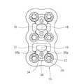
도 3은 본 발명에 따른 경추고정장치의 고정날개가 중간영역에 있는 상태를나타낸 평면도이다.
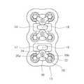
도 4는 도 3에 도시된 고정날개가 90˚회전한 상태를 나타낸 평면도이다.
도 5는 도 3에 도시된 고정날개가 회전영역에 있는 상태를 나타낸 평면도이다.1 is an exploded perspective view of a cervical spine fixation device according to the present invention.
2 is a rear view of the cervical spine fixation device according to the present invention.
FIG. 3 is a plan view showing a state where a fixed blade of a cervical spine fixation device according to the present invention is in an intermediate region.
4 is a plan view showing a state where the fixed blade shown in FIG. 3 is rotated by 90 degrees.
5 is a plan view showing a state in which the fixed blade shown in FIG. 3 is in a rotating region.
이하, 본 발명에 따른 경추고정장치의 바람직한 실시예들을 도면을 참조하여 상세하게 설명한다. 이하에서 사용된 용어나 단어는 통상적이거나 사전적인 의미로 한정해서 해석되어서는 아니되며, 발명자는 그 자신의 발명을 최선의 방법으로 설명하기 위해 용어의 개념을 적절하게 정의할 수 있다는 원칙에 입각하여 본 발명의 기술적 사상에 부합하는 의미와 개념으로 해석되어야 할 것이다.Hereinafter, preferred embodiments of a cervical spine fixation device according to the present invention will be described in detail with reference to the drawings. It is to be understood that the terminology or words used herein are not to be construed in an ordinary sense or a dictionary, and that the inventor can properly define the concept of a term to describe its invention in the best possible way And should be construed in accordance with the meaning and concept consistent with the technical idea of the present invention.
도 1을 참조하면, 본 발명에 따른 경추고정장치(1)는 플레이트(10)에 삽입된 뼈 나사(20)를 원하는 각도로 용이하게 고정시킬 수 있는 것으로, 플레이트(10)와, 뼈 나사(20)와, 잠금부(30)를 포함한다.1, a cervical
상기 플레이트(10)는 사람과 동물의 신체 내부에 발생된 골편(bone fragment)을 고정하기 위해서 사용되는 고정수단으로서, 그 형상은 대략 직육면체의 판넬 형상이되 상기 뼈 나사(20)가 결합되는 부위의 곡면을 따라 외측으로 돌출되어 있으며, 골편의 형상에 따라 플레이트(10)의 형상도 변할 수 있다.The
상기 플레이트(10)는 티타늄(Titanium) 등의 강성의 금속 소재 또는 폴리에테르에테르케톤(Polyether ether ketone)과 같은 폴리머 소재로 이루어질 수 있다. 그러나 상기 플레이트(10)의 형상과 재료는 이에 한정되지 않으며, 인체에 삽입시 거부반응을 일으키지 않는 골편 고정 강성을 가진 재료가 사용될 수 있다. 이러한 플레이트(10)는 나사 삽입홀(12a, 12b, 12c)과, 단차부(16, 17)를 포함한다.The
상기 나사 삽입홀(12a, 12b, 12c)은 후술할 뼈 나사(20)가 삽입 체결되는 것으로, 상기 플레이트(10)의 상면에서 하면 방향으로 관통되는 삽입로가 형성된다. 상기 나사 삽입홀(12a, 12b, 12c)은 상기 플레이트(10)의 길이방향 축에 대해 대칭이 되도록 형성되며, 도 1에는 3쌍의 나사 삽입홀(12a, 12b, 12c)이 도시되어 있다. 그러나, 상기 나사 삽입홀(12a, 12b, 12c)이 플레이트(10)에 3쌍 이상 마련되거나 그보다 적게 마련될 수 있음은 물론이다.The
상기 나사 삽입홀(12a, 12b, 12c)에 형성된 중심축은 플레이트(10)의 상하면에 대해 수직으로 구성될 수 있으나, 일정 각도를 가지고 구성될 수도 있다. 예를 들어, 도 1에 도시된 3쌍의 나사 삽입홀(12a, 12b, 12c) 중 상단 1쌍의 나사 삽입홀(12a)의 중심축은 서로 만나는 방향으로 구성될 수 있고, 중단 1쌍의 나사 삽입홀(12b)의 중심축은 각각 플레이트(10)의 상하면에 수직으로 구성될 수 있으며, 하단 1쌍의 나사 삽입홀(12c)의 중심축은 서로 멀어지는 방향으로 구성될 수 있다. 이러한 중심축의 각도는 고정하려는 골편의 모양에 따라 상기 나사 삽입홀(12a, 12b, 12c)을 중심축 방향으로 가공함으로써 형성된다.The central axis formed in the
상기 나사 삽입홀(12a, 12b, 12c)은 후술할 뼈 나사(20)가 경추에 삽입된 후 플레이트(10)가 뼈 나사(20)의 삽입방향과 반대방향으로 인출되지 않도록 나사 삽입홀(12a, 12b, 12c)의 내주면이 테이퍼 면으로 형성되거나, 상단홀과 하단홀을 통해 걸림턱을 가지는 카운터 보어자리로 형성될 수 있다. 본 발명의 일실시예에서는 나사 삽입홀(12a, 12b, 12c)의 내주면이 테이퍼 면으로 형성된 것을 중심으로 설명한다. The
상기 단차부(16, 17)는 후술할 잠금부(30)를 안착시키기 위해 플레이트(10)의 상면에서 하면 방향으로 단차가 형성된 영역으로, 회전영역과, 중간영역으로 구성될 수 있다. 도 1을 참조하면, 상기 단차부(16, 17)는 제1 단차부(16)와 제2 단차부(17)를 갖는데, 제1 단차부(16)에는 중간영역을 중심으로 대칭되는 한 쌍의 회전영역을 가지며, 제2 단차부(17)는 중간영역과 회전영역을 갖는다.The
상기 회전영역은 한 쌍의 나사 삽입홀(12a, 12b, 12c) 사이마다 마련되며, 후술할 잠금부(30)가 회전할 수 있도록 일정한 곡률을 가진 회전경로를 갖는다. 상기 회전영역에는 플레이트(10)의 상면에서 하면 방향으로 연장되어 관통하는 잠금부 삽입홀(14a, 14b, 14c)이 마련된다. 따라서 상술한 나사 삽입홀(12a, 12b, 12c)의 깊이와 잠금부 삽입홀(14a, 14b, 14c)의 깊이는 단차만큼 차이가 나게 된다.The rotation region is provided between the pair of
상기 중간영역은 회전영역과 연결되고, 한 쌍의 나사 삽입홀(12a, 12b)과 다른 쌍의 나사 삽입홀(12b, 12c) 사이에 마련되며, 회전영역에 있는 복수의 잠금부(30) 간 회전을 방해하지 않도록 플레이트(10)의 길이방향을 따라 소정거리 이격된 크기를 갖는다. 상기 중간영역에는 플레이트(10)를 관통하는 형태로 형성되어 경추고정장치(1)의 시술상태를 용이하게 파악할 수 있도록 하는 투시홀(18, 19)이 마련된다.The intermediate region is connected to the rotating region and is provided between the pair of
도 1을 참조하면, 상기 단차부(16, 17)는 제1 단차부(16)와 제2 단차부(17)를 갖는데, 제1 단차부(16)에는 중간영역을 중심으로 대칭되는 한 쌍의 회전영역을 가지며, 제2 단차부(17)는 중간영역과 회전영역을 갖는다. 그러나 상술한 바와 같이 상기 나사 삽입홀(12a, 12b, 12c)이 4개의 쌍을 갖는다면 제2 단차부(17)는 제1 단차부(16)와 같은 중간영역과 회전영역을 가질 수 있다.Referring to FIG. 1, the
상기 뼈 나사(20)는 플레이트(10)의 나사 삽입홀(12a, 12b, 12c)에 삽입체결되기 위해 헤드부(22)와 샤프트(24)를 가질 수 있다.The
상기 헤드부(22)의 상면에는 상기 뼈 나사(20)를 경추(미도시)에 체결시키도록 체결기구(미도시)가 끼워지는 체결기구홈(26)이 형성될 수 있다. 도 1에서는 상기 체결기구홈(26)이 별모양으로 형성되어 있으나, 체결기구홈(26)과 체결기구(미도시)의 체결이 이루어지는 다른 형상으로 형성될 수 있다.On the upper surface of the
상기 헤드부(22)의 외주면은 상기 나사 삽입홀(12a, 12b, 12c)의 내주면과 대응되도록 테이퍼 면으로 형성될 수 있다. 즉, 이러한 헤드부(22)의 내주면 형상에 의해 상기 나사 삽입홀(12a, 12b, 12c)의 내주면과 상기 뼈 나사(20)의 외주면은 경사지게 압착접촉될 수 있으므로, 뼈 나사(20)가 경추에 삽입된 후에는 플레이트(10)의 인출이 방지된다.The outer circumferential surface of the
상기 샤프트(24)는 일단이 상기 헤드부(22)와 일체로 결합되고, 타단으로 갈수록 경사지게 형성되어 나사의 형태를 갖는다. 상기 샤프트(24)의 외주면에는 경추에 용이하게 체결될 수 있도록 일방향으로 형성된 나사산이 마련된다.One end of the
한편, 상술한 바와 같이 상기 나사 삽입홀(12a, 12b, 12c)은 삽입축이 일정한 각도로 기울어지도록 가공될 수 있으므로, 기울어진 나사 삽입홀(12a, 12b, 12c)에 삽입된 뼈 나사(20)는 나사 삽입홀(12a, 12b, 12c)의 중심축 방향을 따라 기울어지면서 이동하다가 경추에 나사결합을 하게 된다. 따라서 나사 삽입홀(12a, 12b, 12c)의 중심축 각도에 따라 여러 형상의 골편 고정작업이 이루어질 수 있다.Since the insertion axes of the
상기 뼈 나사(20)의 상면 직경은 상기 나사 삽입홀(12a, 12b, 12c)의 상면 직경보다 작게 마련될 수 있다. 따라서 뼈 나사(20)가 나사 삽입홀(12a, 12b, 12c)에 삽입되어 이동하다가 뼈 나사(20)의 상면 직경이 나사 삽입홀(12a, 12b, 12c)의 내주면 중 뼈 나사(20)의 상면 직경과 동일한 직경을 가진 부위에서 정지하므로, 상기 뼈 나사(20)의 상면은 나사 삽입홀(12a, 12b, 12c)의 상면 밖으로 돌출되지 않는다.The upper surface diameter of the
상기 잠금부(30)는 플레이트(10)에 삽입되고 회전각도에 따라 뼈 나사(20)의 인출을 방지하도록 고정하기 위한 것으로, 수직부(32)와 수평부(34)를 포함한다.The locking
도 1 및 도 2를 참조하면, 상기 수직부(32)는 플레이트(10)에 마련된 잠금부 삽입홀(14a, 14b, 14c)에 삽입되어 회전할 수 있도록 중공을 가진 원통형상으로 이루어진다. 상기 잠금부(30)가 잠금부 삽입홀(14a, 14b, 14c)에 삽입된 상태에서, 상기 수직부(32)의 일단이 후술할 수평부(34)에 결합되어 일체를 이루면서 상기 잠금부(30)의 하향 방향으로의 인출이 방지되고, 수직부(32)의 타단이 성형 머리부(33a)를 형성하여 상기 잠금부(30)의 상향 방향으로의 인출이 방지된다.Referring to FIGS. 1 and 2, the
상기 수평부(34)에는 상기 수직부(32)의 중공과 연통되도록 회전홀(36)이 마련된다. 상기 회전홀(36)에 드라이버(미도시) 등이 삽입되어 회전하면 일체로 형성된 수직부(32)와 수평부(34)는 상기 회전홀(36)의 중심축을 기준으로 상기 단차부(16, 17)의 회전영역에서 회전하는 것이 가능하다. 상기 수평부(34)가 잠금부 삽입홀(14a, 14b, 14c)에 삽입된 상태에서는 회전영역의 단차 깊이로 인해 수평부(34)의 상면은 플레이트(10)의 상면과 거의 일치하게 된다. 따라서 환자의 움직임으로 인해 상기 잠금부(30)가 외부에 걸리는 현상은 방지될 수 있다.The
상기 수평부(34)의 양측에는 회전 각도에 따라 상기 나사 삽입홀(12a, 12b, 12c)의 상면을 폐쇄하고 상기 단차부(16, 17)의 회전영역에서 회전이 용이하도록 고정날개(35a, 35b)가 마련된다. 도 1에 도시된 바에 의하면, 상기 회전홀(36)의 중심축과 상기 고정날개(35a, 35b)를 잇는 연장선들 사이의 각도(이하 날개각이라 한다.)가 120˚인 2개의 고정날개(35a, 35b)가 도시되어 있다. 그러나 상기 날개각은 잠금부 삽입홀(14a, 14b, 14c)의 중심축에서 잠금부 삽입홀(14a, 14b, 14c)에 인접한 나사 삽입홀(12a, 12b, 12c)의 중심축을 잇는 연장선들 사이의 각(이하 폐쇄각이라 한다.)이 일치하도록 설정될 수 있다. 예를 들어, 폐쇄각이 180˚라면 날개각도가 180˚로 설정될 수 있다. 또한, 상기 고정날개(35a, 35b)의 개수는 잠금부(30)에 의해 나사 삽입홀(12a, 12b, 12c)의 상면을 폐쇄할 수 있다면 2개에 한정되지 않고 이보다 많게 구성될 수 있으며, 고정날개(35a, 35b)의 크기 및 형상도 다양하게 구성될 수 있다.On both sides of the
도 3 내지 도 5를 참조하여 잠금부(30)의 동작을 상세하게 살펴본다.The operation of the
도 3을 참조하면, 상기 플레이트(10)의 나사 삽입홀(12a, 12b, 12c)에는 뼈 나사(20)가 삽입되어 있고, 잠금부 삽입홀(14a, 14b, 14c)에는 잠금부(30)가 삽입되어 있다. 제1 단차부(16)의 상단 잠금부 삽입홀(14a)에 삽입된 잠금부(30)의 고정날개(35a, 35b)와 하단 잠금부 삽입홀(14b)에 삽입된 잠금부(30)의 고정날개(35a, 35b)는 제1 단차부(16)의 중심영역을 기준으로 서로 대향되게 마주보고 있으며, 제2 단차부(17)의 잠금부 삽입홀(14c)에 삽입된 잠금부(30)의 고정날개(35a, 35b)는 제2 단차부(17)의 중심영역을 향하도록 설정된다. 이와 같이 설정되면, 상기 고정날개(35a, 35b)는 나사 삽입홀(12a, 12b, 12c)의 상면을 개방하게 된다. 따라서, 상기 고정날개(35a, 35b)가 단차부(30)의 중심영역을 향하게 되면 고정날개(35a, 35b)가 나사 삽입홀(12a, 12b, 12c)에 삽입된 뼈 나사(20)를 고정하지 못함을 알 수 있다.3, bone screws 20 are inserted into the
도 4를 참조하면, 도 3에 도시된 고정날개(35a, 35b)가 상기 회전홀(36)의 중심축을 기준으로 90˚회전한 모습이 도시되어 있다. 이러한 상태에서는 상기 고정날개(35a, 35b)는 나사 삽입홀(12a, 12b, 12c)의 상면을 폐쇄하지 못한다.Referring to FIG. 4, the fixed
도 5를 참조하면, 도 4에 도시된 고정날개(35a, 35b)가 상기 회전홀(36)의 중심축을 기준으로 90˚ 더 회전한 모습이 도시되어 있다. 이 상태에서 상기 고정날개(35a, 35b)의 날개각은 폐쇄각과 동일하게 되고, 상기 날개각이 나사 삽입홀(12a, 12b, 12c)의 상면을 폐쇄하게 되므로 나사 삽입홀(12a, 12b, 12c)에 삽입된 뼈 나사(20)의 인출이 방지된다. 이와 같은 과정에 의해 잠금부(30)의 회전만으로 플레이트(10)에 삽입된 뼈 나사(20)의 인출방지가 수월하게 이루어지게 된다.Referring to FIG. 5, the fixed
이하, 본 발명에 따른 경추고정장치(1)를 이용한 시술방법을 설명한다.Hereinafter, an operation method using the cervical
우선, 시술자는 경추 골절 등을 입은 환자의 환부에 케이지 등 시술물을 시술하고 시술자는 투시홀(18, 19)을 통해 환부의 정확한 위치를 확인하면서 플레이트(10)를 환부에 덮는다.First, the practitioner applies a treatment such as a cage to the affected part of the patient who has suffered a cervical vertebra fracture or the like, and the operator covers the
플레이트(10)가 환부의 정확한 위치가 접촉되면, 시술자는 플레이트(10)에 형성된 잠금부(30)가 나사 삽입홀(12a, 12b, 12c)의 상면을 개방한 상태로 회전하고, 뼈 나사(20)를 나사 삽입홀(12a, 12b, 12c)에 삽입한다.When the
그 후, 시술자는 삽입된 뼈 나사(20)의 체결기구홈(26)에 체결기구(미도시)를 체결하고 뼈 나사(20)를 일방향으로 회전시켜 골절된 경추에 나사결합을 실시한다.Thereafter, the operator inserts a fastening mechanism (not shown) into the
플레이트(10)에 형성된 나사 삽입홀(12a, 12b, 12c)을 통해 뼈 나사(20)가 모두 나사결합되면, 시술자는 드라이버(미도시) 등의 회전 공구를 잠금부(30)에 형성된 회전홀(36)에 삽입하여 회전시키고, 상기 잠금부(30)가 나사 삽입홀(12a, 12b, 12c)의 상면을 모두 폐쇄하면 회전을 멈춘다.When the bone screws 20 are all screwed through the
이상과 같이, 본 발명은 비록 한정된 실시예와 도면에 의해 설명되었으나, 본 발명은 이에 한정되지 않으며 본 발명이 속하는 기술분야에서 통상의 지식을 가진 자에 의해 본 발명의 기술사상과 아래에 기재될 특허청구범위의 균등범위 내에서 다양하게 수정 및 변형될 수 있음은 물론이다.While the present invention has been particularly shown and described with reference to exemplary embodiments thereof, it is to be understood that the invention is not limited thereto and that various changes and modifications may be made therein without departing from the spirit and scope of the invention as defined by the appended claims. And various changes and modifications may be made without departing from the scope of the appended claims.
1 : 경추고정장치10 : 플레이트
12a, 12b, 12c : 나사 삽입홀 14a, 14b, 14c : 잠금부 삽입홀
16 : 제1 단차부17 : 제2 단차부
18 : 투시홀19 : 투시홀
20 : 뼈 나사22 : 헤드부
24 : 샤프트26 : 체결기구홈
30 : 잠금부32 : 수직부
33 : 성형 머리부34 : 수평부
35a, 35b : 고정날개36 : 회전홀1: cervical fixation device 10: plate
12a, 12b, 12c: screw
16: first step 17: second step
18: through hole 19: through hole
20: bone screw 22: head part
24: shaft 26: fastening mechanism groove
30: locking part 32: vertical part
33: forming head 34: horizontal part
35a, 35b: fixed blade 36: rotary hole
Claims (6)
Translated fromKorean상기 나사 삽입홀에 삽입되어 회전을 통해 골편과 나사결합되는 뼈 나사; 및
상기 플레이트에 회전가능하게 결합되어 상기 나사 삽입홀의 상면을 개폐하는 잠금부;를 포함하고,
상기 플레이트의 상면에는 일정 깊이의 단차부가 형성되고,
상기 단차부는 상기 잠금부의 회전이 가능한 회전영역이 마련되며,
상기 회전영역에는 상기 잠금부가 삽입되도록 잠금부 삽입홀이 형성되고,
상기 잠금부는,
상기 잠금부 삽입홀에 삽입되는 수직부;를 포함하고,
상기 수직부의 일단은 상기 잠금부 삽입홀에 삽입된 후 상기 잠금부의 인출이 방지되도록 성형 머리부가 형성되는 경추고정장치.A plate having a plurality of screw insertion holes formed therein;
A bone screw inserted into the screw insertion hole and screwed to the bone piece through rotation; And
And a lock portion rotatably coupled to the plate to open and close an upper surface of the screw insertion hole,
A stepped portion having a predetermined depth is formed on an upper surface of the plate,
Wherein the stepped portion is provided with a rotation region in which the lock portion is rotatable,
A locking portion insertion hole is formed in the rotation region so that the locking portion is inserted,
The locking portion
And a vertical portion inserted into the locking portion insertion hole,
And a shaping head is formed at one end of the vertical portion so as to prevent the locking portion from being pulled out after being inserted into the locking portion insertion hole.
상기 잠금부는,
상기 수직부와 일체로 결합하여 상기 회전영역에 면접하는 수평부; 및
상기 수평부에 형성되어 상기 회전영역에 인접하는 2개의 나사 삽입홀의 상면을 동시에 개폐하는 복수의 고정날개;를 포함하는 경추고정장치.The method according to claim 1,
The locking portion
A horizontal portion which is integrally combined with the vertical portion and is in contact with the rotation region; And
And a plurality of fixed vanes formed on the horizontal portion and simultaneously opening and closing upper surfaces of two screw insertion holes adjacent to the rotation region.
상기 복수의 고정날개 사이의 각도는 120°인 것을 특징으로 하는 경추고정장치.3. The method of claim 2,
And an angle between the plurality of fixed wings is 120 DEG.
상기 단차부에 마련된 복수의 회전영역 사이에는 상기 잠금부의 회전을 인도하도록 중간영역이 마련되며,
상기 회전영역에 놓인 상기 고정날개는 상기 나사 삽입홀의 상면을 폐쇄하고, 상기 중간영역에 놓인 상기 고정날개는 상기 나사 삽입홀의 상면을 개방하는 경추고정장치.3. The method of claim 2,
An intermediate region is provided between the plurality of rotation regions provided in the step portion to guide the rotation of the lock portion,
Wherein the fixed blade located in the rotation region closes the upper surface of the screw insertion hole and the fixed blade placed in the middle region opens the upper surface of the screw insertion hole.
상기 수평부에는 회전공구와 체결되어 상기 잠금부를 회전시킬 수 있도록 회전홀이 형성되는 경추고정장치.3. The method of claim 2,
Wherein the horizontal portion is formed with a rotation hole that is coupled to the rotary tool to rotate the locking portion.
Priority Applications (4)
| Application Number | Priority Date | Filing Date | Title |
|---|---|---|---|
| KR1020170100466AKR101989823B1 (en) | 2017-08-08 | 2017-08-08 | Apparatus for fixing a cervical spine |
| US15/716,774US10405900B2 (en) | 2017-08-08 | 2017-09-27 | Apparatus for fixing cervical spine |
| CN201710900946.7ACN109381249A (en) | 2017-08-08 | 2017-09-28 | Cervical vertebrae fixer |
| JP2017197554AJP6574822B2 (en) | 2017-08-08 | 2017-10-11 | Cervical spine fixation device |
Applications Claiming Priority (1)
| Application Number | Priority Date | Filing Date | Title |
|---|---|---|---|
| KR1020170100466AKR101989823B1 (en) | 2017-08-08 | 2017-08-08 | Apparatus for fixing a cervical spine |
Publications (2)
| Publication Number | Publication Date |
|---|---|
| KR20190016349A KR20190016349A (en) | 2019-02-18 |
| KR101989823B1true KR101989823B1 (en) | 2019-06-17 |
Family
ID=65274403
Family Applications (1)
| Application Number | Title | Priority Date | Filing Date |
|---|---|---|---|
| KR1020170100466AActiveKR101989823B1 (en) | 2017-08-08 | 2017-08-08 | Apparatus for fixing a cervical spine |
Country Status (4)
| Country | Link |
|---|---|
| US (1) | US10405900B2 (en) |
| JP (1) | JP6574822B2 (en) |
| KR (1) | KR101989823B1 (en) |
| CN (1) | CN109381249A (en) |
Families Citing this family (5)
| Publication number | Priority date | Publication date | Assignee | Title |
|---|---|---|---|---|
| US10245080B2 (en)* | 2014-06-04 | 2019-04-02 | Mohammad Etminan | System for mounting of a cervical plate to a vertebra |
| US20190209215A1 (en)* | 2018-01-05 | 2019-07-11 | Atlas Spine, Inc. | Locking cervical plate |
| CN109288571A (en)* | 2018-11-09 | 2019-02-01 | 中国人民解放军第二军医大学第二附属医院 | Cervical vertebra natural height fixing plate |
| KR102285459B1 (en)* | 2019-04-15 | 2021-08-02 | 경북대학교 산학협력단 | Cervical fixation plate |
| KR102596974B1 (en)* | 2023-05-23 | 2023-11-02 | (주)서지오젠 | Cervical plate for easy reoperation |
Citations (1)
| Publication number | Priority date | Publication date | Assignee | Title |
|---|---|---|---|---|
| JP2008100101A (en)* | 1997-05-15 | 2008-05-01 | Warsaw Orthopaedic Inc | Plate device for anterior neck |
Family Cites Families (30)
| Publication number | Priority date | Publication date | Assignee | Title |
|---|---|---|---|---|
| ES2297092T3 (en) | 1997-02-11 | 2008-05-01 | Warsaw Orthopedic, Inc. | PREVIOUS CERVICAL PLATE OF UNIQUE BLOCK. |
| US6139550A (en)* | 1997-02-11 | 2000-10-31 | Michelson; Gary K. | Skeletal plating system |
| US5951558A (en)* | 1998-04-22 | 1999-09-14 | Fiz; Daniel | Bone fixation device |
| US20040220571A1 (en)* | 1998-04-30 | 2004-11-04 | Richard Assaker | Bone plate assembly |
| FR2778088B1 (en)* | 1998-04-30 | 2000-09-08 | Materiel Orthopedique En Abreg | ANTERIOR IMPLANT, PARTICULARLY FOR THE CERVICAL RACHIS |
| FR2784570B1 (en)* | 1998-10-19 | 2001-02-16 | Scient X | INTERVERTEBRAL CONNECTION DEVICE HAVING ANTI-EXTRACTION MEANS FOR ANCHORAGE SCREWS |
| FR2823096B1 (en)* | 2001-04-06 | 2004-03-19 | Materiel Orthopedique En Abreg | PLATE FOR LTE AND LTE VERTEBRATE OSTEOSYNTHESIS DEVICE, OSTEOSYNTHESIS DEVICE INCLUDING SUCH A PLATE, AND INSTRUMENT FOR LAYING SUCH A PLATE |
| US7041105B2 (en)* | 2001-06-06 | 2006-05-09 | Sdgi Holdings, Inc. | Dynamic, modular, multilock anterior cervical plate system having detachably fastened assembleable and moveable segments |
| US7044952B2 (en)* | 2001-06-06 | 2006-05-16 | Sdgi Holdings, Inc. | Dynamic multilock anterior cervical plate system having non-detachably fastened and moveable segments |
| US6890335B2 (en)* | 2001-08-24 | 2005-05-10 | Zimmer Spine, Inc. | Bone fixation device |
| US6695846B2 (en)* | 2002-03-12 | 2004-02-24 | Spinal Innovations, Llc | Bone plate and screw retaining mechanism |
| US6945973B2 (en)* | 2003-05-01 | 2005-09-20 | Nuvasive, Inc. | Slidable bone plate system |
| KR100552117B1 (en) | 2003-07-22 | 2006-02-13 | 유앤아이 주식회사 | Cervical vertebrae device and driver used in it |
| US7306605B2 (en)* | 2003-10-02 | 2007-12-11 | Zimmer Spine, Inc. | Anterior cervical plate |
| US7727266B2 (en)* | 2004-06-17 | 2010-06-01 | Warsaw Orthopedic, Inc. | Method and apparatus for retaining screws in a plate |
| US7452370B2 (en)* | 2005-04-29 | 2008-11-18 | Warsaw Orthopedic, Inc | Apparatus for retaining a bone anchor in a bone plate and method for use thereof |
| US7875062B2 (en)* | 2006-03-07 | 2011-01-25 | Warsaw Orthopedic, Inc. | Methods and devices for retaining bone plate anchors |
| US7674279B2 (en)* | 2006-10-13 | 2010-03-09 | Spinal U.S.A. | Bone plate |
| EP3184065B1 (en)* | 2007-11-09 | 2019-06-19 | Stryker European Holdings I, LLC | Cervical plate with a feedback device for selective association with bone screw blocking mechanism |
| US8652182B1 (en)* | 2008-10-01 | 2014-02-18 | Spinal U.S.A. | Bone plate with retainer and stop for screw lock |
| US8486115B2 (en)* | 2009-03-13 | 2013-07-16 | Lanx, Inc. | Spinal plate assemblies with backout protection cap and methods |
| JP5662442B2 (en)* | 2009-07-24 | 2015-01-28 | スパイナル・ユーエスエー・エルエルシー | Bone plate screw block system and method |
| US8454667B2 (en)* | 2010-12-16 | 2013-06-04 | Warsaw Orhtopedic, Inc. | Retaining mechanism |
| US8932335B2 (en)* | 2012-08-31 | 2015-01-13 | Warsaw Orthopedic, Inc. | Retaining mechanism |
| CN103932774A (en)* | 2014-04-14 | 2014-07-23 | 北京市奥斯比利克新技术开发有限公司 | Locking device for spiral groove of anterior cervical steel plate |
| US20160095637A1 (en) | 2014-10-05 | 2016-04-07 | Nexxt Spine, LLC | Locking mechanism for a cervical fixation plate |
| KR101608949B1 (en)* | 2014-11-19 | 2016-04-04 | 경북대학교 산학협력단 | A system for fixing cervical vertebrae, an appratus for fixing cervical vertebrae and a driver used for an appratus for fixing cervical vertebrae |
| US9381093B1 (en)* | 2015-02-09 | 2016-07-05 | Alliance Partners, Llc | Locking device for fixation mechanism of medical implant |
| US20170065311A1 (en) | 2015-09-04 | 2017-03-09 | GS Medical Inc. | Anterior cervical plate |
| CN105342680A (en)* | 2015-10-13 | 2016-02-24 | 广州聚生生物科技有限公司 | Anterior cervical interbody steel plate cage integrated internal fixing system |
- 2017
- 2017-08-08KRKR1020170100466Apatent/KR101989823B1/enactiveActive
- 2017-09-27USUS15/716,774patent/US10405900B2/enactiveActive
- 2017-09-28CNCN201710900946.7Apatent/CN109381249A/enactivePending
- 2017-10-11JPJP2017197554Apatent/JP6574822B2/enactiveActive
Patent Citations (1)
| Publication number | Priority date | Publication date | Assignee | Title |
|---|---|---|---|---|
| JP2008100101A (en)* | 1997-05-15 | 2008-05-01 | Warsaw Orthopaedic Inc | Plate device for anterior neck |
Also Published As
| Publication number | Publication date |
|---|---|
| CN109381249A (en) | 2019-02-26 |
| JP2019030621A (en) | 2019-02-28 |
| KR20190016349A (en) | 2019-02-18 |
| JP6574822B2 (en) | 2019-09-11 |
| US20190046245A1 (en) | 2019-02-14 |
| US10405900B2 (en) | 2019-09-10 |
Similar Documents
| Publication | Publication Date | Title |
|---|---|---|
| KR101989823B1 (en) | Apparatus for fixing a cervical spine | |
| EP1940303B1 (en) | Bone fastening assembly and bushing and screw for use therewith | |
| ES2595308T3 (en) | Intramedullary rod with pivoting bra | |
| KR101413714B1 (en) | Cervical plate system having an insertable rotating element | |
| US10123828B2 (en) | Implantable device with pivotable fastener and self-adjusting set screw | |
| US8790343B2 (en) | Intramedullary rod with pivotable and fixed fasteners and method for using same | |
| US9220544B2 (en) | Implantable device with locking adjustment mechanism and method for using same | |
| KR20120100903A (en) | Protection sleeve retention device | |
| EP3878386B1 (en) | Coupling device for use with a bone anchoring element and bone anchoring device with such a coupling device | |
| JP2011092712A (en) | Interspinous process implant and method of implantation | |
| ES2922488T3 (en) | Method for designing a registration instrument for osteosynthesis and a system comprising the registration instrument | |
| US9763654B2 (en) | Adjustable orthopaedic joint distractor | |
| CN107280749B (en) | Blade structure, hip screw and femoral fracture treatment device | |
| JP7290943B2 (en) | Bone plate for epiphyseal closure | |
| JP3752128B2 (en) | Intramedullary nail positioning device | |
| KR102190053B1 (en) | Clamp device for surgical guide wire | |
| JP7025615B2 (en) | Fixture for fracture treatment | |
| JP2005304607A (en) | Fixation device for fracture treatment | |
| KR20060063888A (en) | Aiming device |
Legal Events
| Date | Code | Title | Description |
|---|---|---|---|
| A201 | Request for examination | ||
| PA0109 | Patent application | St.27 status event code:A-0-1-A10-A12-nap-PA0109 | |
| PA0201 | Request for examination | St.27 status event code:A-1-2-D10-D11-exm-PA0201 | |
| D13-X000 | Search requested | St.27 status event code:A-1-2-D10-D13-srh-X000 | |
| D14-X000 | Search report completed | St.27 status event code:A-1-2-D10-D14-srh-X000 | |
| E902 | Notification of reason for refusal | ||
| PE0902 | Notice of grounds for rejection | St.27 status event code:A-1-2-D10-D21-exm-PE0902 | |
| E13-X000 | Pre-grant limitation requested | St.27 status event code:A-2-3-E10-E13-lim-X000 | |
| P11-X000 | Amendment of application requested | St.27 status event code:A-2-2-P10-P11-nap-X000 | |
| P13-X000 | Application amended | St.27 status event code:A-2-2-P10-P13-nap-X000 | |
| PG1501 | Laying open of application | St.27 status event code:A-1-1-Q10-Q12-nap-PG1501 | |
| PE0801 | Dismissal of amendment | St.27 status event code:A-2-2-P10-P12-nap-PE0801 | |
| E701 | Decision to grant or registration of patent right | ||
| GRNT | Written decision to grant | ||
| PE0701 | Decision of registration | St.27 status event code:A-1-2-D10-D22-exm-PE0701 | |
| PR0701 | Registration of establishment | St.27 status event code:A-2-4-F10-F11-exm-PR0701 | |
| PR1002 | Payment of registration fee | St.27 status event code:A-2-2-U10-U11-oth-PR1002 Fee payment year number:1 | |
| PG1601 | Publication of registration | St.27 status event code:A-4-4-Q10-Q13-nap-PG1601 | |
| PR1001 | Payment of annual fee | St.27 status event code:A-4-4-U10-U11-oth-PR1001 Fee payment year number:4 | |
| PR1001 | Payment of annual fee | St.27 status event code:A-4-4-U10-U11-oth-PR1001 Fee payment year number:5 | |
| PR1001 | Payment of annual fee | St.27 status event code:A-4-4-U10-U11-oth-PR1001 Fee payment year number:6 | |
| PN2301 | Change of applicant | St.27 status event code:A-5-5-R10-R13-asn-PN2301 St.27 status event code:A-5-5-R10-R11-asn-PN2301 | |
| PN2301 | Change of applicant | St.27 status event code:A-5-5-R10-R13-asn-PN2301 St.27 status event code:A-5-5-R10-R11-asn-PN2301 |