KR101987723B1 - Fluid cartridge - Google Patents
Fluid cartridgeDownload PDFInfo
- Publication number
- KR101987723B1 KR101987723B1KR1020187016736AKR20187016736AKR101987723B1KR 101987723 B1KR101987723 B1KR 101987723B1KR 1020187016736 AKR1020187016736 AKR 1020187016736AKR 20187016736 AKR20187016736 AKR 20187016736AKR 101987723 B1KR101987723 B1KR 101987723B1
- Authority
- KR
- South Korea
- Prior art keywords
- cartridge
- latch
- interface
- fluid
- track
- Prior art date
- Legal status (The legal status is an assumption and is not a legal conclusion. Google has not performed a legal analysis and makes no representation as to the accuracy of the status listed.)
- Active
Links
Images


Classifications
- B—PERFORMING OPERATIONS; TRANSPORTING
- B41—PRINTING; LINING MACHINES; TYPEWRITERS; STAMPS
- B41L—APPARATUS OR DEVICES FOR MANIFOLDING, DUPLICATING OR PRINTING FOR OFFICE OR OTHER COMMERCIAL PURPOSES; ADDRESSING MACHINES OR LIKE SERIES-PRINTING MACHINES
- B41L27/00—Inking arrangements or devices
- B—PERFORMING OPERATIONS; TRANSPORTING
- B41—PRINTING; LINING MACHINES; TYPEWRITERS; STAMPS
- B41J—TYPEWRITERS; SELECTIVE PRINTING MECHANISMS, i.e. MECHANISMS PRINTING OTHERWISE THAN FROM A FORME; CORRECTION OF TYPOGRAPHICAL ERRORS
- B41J2/00—Typewriters or selective printing mechanisms characterised by the printing or marking process for which they are designed
- B41J2/005—Typewriters or selective printing mechanisms characterised by the printing or marking process for which they are designed characterised by bringing liquid or particles selectively into contact with a printing material
- B41J2/01—Ink jet
- B41J2/17—Ink jet characterised by ink handling
- B41J2/175—Ink supply systems ; Circuit parts therefor
- B41J2/17503—Ink cartridges
- B41J2/17526—Electrical contacts to the cartridge
- B—PERFORMING OPERATIONS; TRANSPORTING
- B41—PRINTING; LINING MACHINES; TYPEWRITERS; STAMPS
- B41J—TYPEWRITERS; SELECTIVE PRINTING MECHANISMS, i.e. MECHANISMS PRINTING OTHERWISE THAN FROM A FORME; CORRECTION OF TYPOGRAPHICAL ERRORS
- B41J2/00—Typewriters or selective printing mechanisms characterised by the printing or marking process for which they are designed
- B41J2/005—Typewriters or selective printing mechanisms characterised by the printing or marking process for which they are designed characterised by bringing liquid or particles selectively into contact with a printing material
- B41J2/01—Ink jet
- B41J2/17—Ink jet characterised by ink handling
- B41J2/175—Ink supply systems ; Circuit parts therefor
- B41J2/17503—Ink cartridges
- B41J2/17513—Inner structure
- B—PERFORMING OPERATIONS; TRANSPORTING
- B41—PRINTING; LINING MACHINES; TYPEWRITERS; STAMPS
- B41J—TYPEWRITERS; SELECTIVE PRINTING MECHANISMS, i.e. MECHANISMS PRINTING OTHERWISE THAN FROM A FORME; CORRECTION OF TYPOGRAPHICAL ERRORS
- B41J2/00—Typewriters or selective printing mechanisms characterised by the printing or marking process for which they are designed
- B41J2/005—Typewriters or selective printing mechanisms characterised by the printing or marking process for which they are designed characterised by bringing liquid or particles selectively into contact with a printing material
- B41J2/01—Ink jet
- B41J2/17—Ink jet characterised by ink handling
- B41J2/175—Ink supply systems ; Circuit parts therefor
- B41J2/17503—Ink cartridges
- B41J2/1752—Mounting within the printer
- B—PERFORMING OPERATIONS; TRANSPORTING
- B41—PRINTING; LINING MACHINES; TYPEWRITERS; STAMPS
- B41J—TYPEWRITERS; SELECTIVE PRINTING MECHANISMS, i.e. MECHANISMS PRINTING OTHERWISE THAN FROM A FORME; CORRECTION OF TYPOGRAPHICAL ERRORS
- B41J2/00—Typewriters or selective printing mechanisms characterised by the printing or marking process for which they are designed
- B41J2/005—Typewriters or selective printing mechanisms characterised by the printing or marking process for which they are designed characterised by bringing liquid or particles selectively into contact with a printing material
- B41J2/01—Ink jet
- B41J2/17—Ink jet characterised by ink handling
- B41J2/175—Ink supply systems ; Circuit parts therefor
- B41J2/17503—Ink cartridges
- B41J2/17543—Cartridge presence detection or type identification
- B41J2/1755—Cartridge presence detection or type identification mechanically
- B—PERFORMING OPERATIONS; TRANSPORTING
- B41—PRINTING; LINING MACHINES; TYPEWRITERS; STAMPS
- B41J—TYPEWRITERS; SELECTIVE PRINTING MECHANISMS, i.e. MECHANISMS PRINTING OTHERWISE THAN FROM A FORME; CORRECTION OF TYPOGRAPHICAL ERRORS
- B41J2/00—Typewriters or selective printing mechanisms characterised by the printing or marking process for which they are designed
- B41J2/005—Typewriters or selective printing mechanisms characterised by the printing or marking process for which they are designed characterised by bringing liquid or particles selectively into contact with a printing material
- B41J2/01—Ink jet
- B41J2/17—Ink jet characterised by ink handling
- B41J2/175—Ink supply systems ; Circuit parts therefor
- B41J2/17503—Ink cartridges
- B41J2/17553—Outer structure
Landscapes
- Ink Jet (AREA)
- Infusion, Injection, And Reservoir Apparatuses (AREA)
- Containers And Packaging Bodies Having A Special Means To Remove Contents (AREA)
- Quick-Acting Or Multi-Walled Pipe Joints (AREA)
Abstract
Translated fromKoreanDescription
Translated fromKorean본 발명은 유체 카트리지에 관한 것이다.The present invention relates to a fluid cartridge.
유체 카트리지는 대응하는 유체 방출 어셈블리에서 교체되는 하위 부품이다. 통상의 유체 카트리지로는 잉크 카트리지가 있다. 통상의 유체 방출 어셈블리는 프린터이다. 일반적으로, 잉크 카트리지는 2가지 타입으로 구분될 수 있다. 제1 타입의 잉크 카트리지는 일체형 프린트 헤드 카트리지로 구성되며, 이 카트리지는 프린트 헤드를 포함한다. 제2 타입의 잉크 카트리지는 개별 잉크 용기로 구성된다. 잉크 카트리지가 프린터의 수용 구조물에 연결된다. 수용 구조물 및 잉크 카트리지는 인쇄를 위해 잉크를 카트리지로부터 프린트 헤드에 안내하기에 적합한 인터페이스가 제공된다. 잉크 카트리지 및 그 수용 구조물에는, 잉크 인터페이스 외에, 공기 인터페이스, 키잉 인터페이스(keying interface), 전기 인터페이스 및 정렬 인터페이스(alignment interface)가 제공될 수 있다. 공기 인터페이스는 대개는 카트리지 내부의 압력 조절을 위해 카트리지에 공기를 이송하고 카트리지로부터 공기를 이송한다. 키잉 인터페이스는 각각의 카트리지가 적합한 잉크 카트리지 수용 구조물에 정확하게 장착되도록 한다. 정렬 인터페이스는 인터페이스들이 연결을 위해 잘 정렬되도록 한다. 전기 인터페이스는 프린터 제어 회로와 잉크 카트리지 간에 전기 신호를 전송한다. 이 전기 신호는 잉크 카트리지 특성에 관한 것일 수도 있다.The fluid cartridge is a subassembly that is replaced in a corresponding fluid ejection assembly. An ordinary fluid cartridge includes an ink cartridge. A typical fluid ejection assembly is a printer. Generally, ink cartridges can be classified into two types. The first type of ink cartridge is comprised of an integral printhead cartridge, which includes a printhead. The ink cartridge of the second type consists of individual ink containers. The ink cartridge is connected to the receiving structure of the printer. The receiving structure and the ink cartridge are provided with an interface suitable for directing the ink from the cartridge to the printhead for printing. In addition to the ink interface, an air interface, a keying interface, an electrical interface, and an alignment interface may be provided to the ink cartridge and its receiving structure. The air interface usually transfers air to and from the cartridge for pressure regulation inside the cartridge. The keying interface allows each cartridge to be correctly mounted in a suitable ink cartridge receiving structure. The alignment interface ensures that the interfaces are well aligned for the connection. The electrical interface transmits electrical signals between the printer control circuit and the ink cartridge. This electrical signal may be related to ink cartridge characteristics.
일반적으로 카트리지와 수용 구조물 간의 실질적으로 기밀 연결 및 액밀 연결(air and liquid tight connection)을 유지하기 위해 여분의 고정부(lock)가 제공된다. 여분의 고정부는 또한 전기 접속을 유지하여야 한다. 공지의 고정 기술은 수용 베이(receiving bay)에 밀봉된 카트리지를 유지하기 위해 베일(bail)을 사용하는 것을 수반한다. 또 다른 공지의 고정 기술은 카트리지를 밀봉된 채로 유지하기 위해 노치(notch)와 결합하는 변형 스냅 핑거(deforming snap finger)를 이용한다.Generally, an extra locking is provided to maintain a substantially airtight and liquid tight connection between the cartridge and the receiving structure. The extra fixture shall also maintain electrical connections. A known anchoring technique involves using a bail to hold the cartridge sealed to the receiving bay. Another known fastening technique utilizes a deforming snap finger that engages a notch to keep the cartridge sealed.
공지의 고정 기구는 프린터 내에서 비교적 많은 양의 공간을 차지하는 경향이 있다. 또한, 고정을 달성하기 위해 커다란 힘이 요구될 수도 있다. 일부 경우, 카트리지를 기울어진 방향으로 삽입하고, 그 후 인터페이스들을 결합시키기 위해 정상적인 자세로 다시 회전된다. 이것은 일반적으로 결합 요소의 휘어짐을 수반하며, 이로써 적절하지 않은 인터페이스 연결, 누출, 및 재료 마모 또는 손상이 발생하기 쉽다.Known fixing mechanisms tend to occupy a relatively large amount of space in the printer. Also, a large force may be required to achieve fixation. In some cases, the cartridges are inserted in an oblique direction and then rotated back to their normal position to engage the interfaces. This generally entails warping of the coupling element, which may result in improper interface connection, leakage, and material wear or damage.
유럽 특허 출원 공개 번호 1348562 A2호는 일체형 프린트헤드 카트리지 및 대응하는 수용 구조물을 개시하고 있다. 수용 구조물은 카트리지를 래치하기 위해 힌지 래치 아암 및 클램프 구조물을 포함한다. 미국 특허 출원 공개 번호 2008/0168481 A1호는 베이스 상으로 슬라이드 가능하게 탑재되는 트레이를 갖는 카트리지를 개시하고 있다. 유럽 특허 출원 공개 번호 EP1122078 A2는 유체 인터커넥트, 키잉 특징부, 및 잉크 용기를 수용 스테이션에 고정하기 위한 래치를 포함하는 교체 가능한 잉크 용기를 개시하고 있다. 미국 특허 출원 번호 2007/0013753 A1호는 뚜껑(lid) 내의 잉크 인터페이스, 공기 인터페이스, 정렬 포켓, 키잉 포켓을 갖는 잉크 용기를 개시하고 있다. 용기를 수용하기 위한 용기 베이(container bay)는 용기를 베이에 래칭하기 위해 용기를 둘러싸는 피봇팅 래칭 부재를 포함한다. 영구 특허 출원 공개 번호 GB 2316657 A는 잉크 출구를 프린터의 잉크 입구에 안내하기 위한 상호 반대측에 배치된 가이드 리브(guide rib)를 갖는 잉크 카트리지를 개시하고 있다. 유럽 특허 번호 1798046 B1은 잉크 카트리지를 개시하고 있으며, 이 잉크 카트리지는, 잉크 카트리지를 사전에 정해진 위치에서 유지하기 위한 바닥면 상의 고정 구조물과, 카트리지를 측방향으로 위치설정하기 위한 전면 상의 위치설정 구멍부를 갖는다.European Patent Application Publication No. 1348562 A2 discloses an integral printhead cartridge and a corresponding receiving structure. The receiving structure includes a hinge latch arm and a clamping structure for latching the cartridge. United States Patent Application Publication No. 2008/0168481 Al discloses a cartridge having a tray slidably mounted on a base. European Patent Application Publication No. EP1122078 A2 discloses a replaceable ink container that includes a fluid interconnect, a keying feature, and a latch for securing the ink container to the receiving station. U.S. Patent Application No. 2007/0013753 A1 discloses an ink container having an ink interface, an air interface, an alignment pocket, and a keying pocket in a lid. The container bay for receiving the container includes a pivoting latching member surrounding the container to latch the container into the bay. Permanent Patent Application Publication No. GB 2316657 A discloses an ink cartridge having guide ribs disposed on mutually opposite sides for guiding the ink outlet to the ink inlet of the printer. European Patent No. 1798046 B1 discloses an ink cartridge comprising a fixing structure on the bottom surface for holding the ink cartridge in a predetermined position and a positioning structure on the front surface for positioning the cartridge in the lateral direction .
본 발명의 특징에 따라, 잉크젯 프린터용 잉크 카트리지가 제공되며, 상기 카트리지는, 바닥면 및 전면과, 카트리지 수용 구조물에 대한 연결을 위한 상기 전면 상의 인터페이스를 포함한다. 상기 인터페이스가 잉크 소켓을 포함한다. 상기 잉크 카트리지는 래치 스톱 및 래치 트랙이 상기 카트리지 수용 구조물의 래치를 안내하고 유지하기 위해 상기 바닥면에 배치된다. 상기 래치 트랙은 고정 트랙 및 해제 트랙을 포함하고, 상기 래치를 상기 래치 스톱에 대하여, 삽입 시에는 상기 고정 트랙을 따라 고정 결합 위치로 이동시키고, 방출 시에는 상기 고정 트랙과는 적어도 부분적으로 상이한 상기 해제 트랙을 따라 해제 위치로 이동시키도록 배치된다. 상기 잉크 카트리지는 또한 상기 인터페이스를 연결하기 위해 상기 잉크 카트리지를 직선(Y)을 따라 안내하기 위하여 상기 카트리지 수용 구조물의 가이드와 결합하는 상기 바닥면의 가이드 트랙을 포함한다. 상기 가이드 트랙은, 상기 직선(Y)과 평행하게 연장하는 가이드 결합 표면을 갖고, 5mm 이상의 길이를 갖는다. 상기 가이드 트랙 및 상기 래치 트랙은 상기 바닥면에서 하나의 일체형 절결부에 의해 형성된다.According to an aspect of the present invention, there is provided an ink cartridge for an ink jet printer, the cartridge including a bottom surface and a front surface, and an interface on the front surface for connection to the cartridge receiving structure. The interface includes an ink socket. The ink cartridge has a latch stop and a latch track disposed on the bottom surface for guiding and holding the latch of the cartridge receiving structure. Wherein the latch track includes a fixed track and an unlock track and moves the latch relative to the latch stop when inserted and to the fixed engagement position along the fixed track and at least partially And is moved to the release position along the release track. The ink cartridge also includes a guide track on the bottom surface that engages the guide of the cartridge receiving structure to guide the ink cartridge along a straight line (Y) to connect the interface. The guide track has a guide engaging surface extending parallel to the straight line Y and has a length of 5 mm or more. The guide track and the latch track are formed by one integral cutout portion on the bottom surface.
예시를 목적으로, 본 발명의 실시예를 이하의 첨부 도면을 참조하여 설명할 것이다.
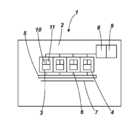
도 1은 유체 방출 시스템의 실시예의 다이아그램의 정면도이다.
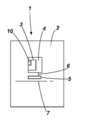
도 2는 도 1의 유체 방출 시스템의 실시예의 다이아그램의 측면도이다.
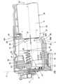
도 3은 유체 카트리지를 연결하지 않은 상태의 유체 방출 시스템의 실시예의 일부분에 대한 측면 횡단면도이다.
도 4는 유체 카트리지를 위한 수용 구조물의 세부구성의 실시예의 정면도이다.
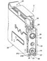
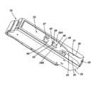
도 5는 유체 카트리지의 실시예의 사시도이다.
도 6은 도 5의 유체 카트리지의 실시예의 또 다른 사시도이며, 가이드 트랙 및 래치 트랙을 명확히 보여주고 있다.
도 7은 도 3의 유체 방출 시스템의 일부분의 실시예의 측면 횡단면도이며, 유체 카트리지가 카트리지 수용 구조물에 연결되어 있는 상태를 나타내고 있다.
도 8은 유체 카트리지를 수용 구조물에 연결하는 방법의 실시예에 대한 흐름도이다.
도 9는 유체 카트리지를 수용 구조물에 대해 연결하고 분리하는 방법의 다른 실시예에 대한 흐름도이다.
도 10은 유체 카트리지를 연결하는 제1 단계에서의 유체 카트리지와 카트리지 수용 구조물의 실시예의 도식적 밑면 횡단면도이며, 예시를 이유로 래치 구성이 반투명하게 되어 있다.
도 11은 유체 카트리지를 연결하는 제2 단계에서의 도 10의 유체 카트리지와 카트리지 수용 구조물의 실시예의 도식적 밑면 횡단면도이며, 예시를 이유로 래치 구성이 반투명하게 되어 있다.
도 12는 유체 카트리지를 연결하는 제3 단계에서의 도 10의 유체 카트리지와 카트리지 수용 구조물의 실시예의 도식적 밑면 횡단면도이며, 예시를 이유로 래치 구성이 반투명하게 되어 있다.
도 13은 유체 카트리지를 연결하는 최종 단계에서의 도 10 내지 도 12의 유체 카트리지와 카트리지 수용 구조물의 실시예의 도식적 밑면 횡단면도이며, 예시를 이유로 래치 구성이 반투명하게 되어 있다.
도 14는 유체 카트리지를 분리하는 제1 단계에서의 도 10 내지 도 13의 유체 카트리지와 카트리지 수용 구조물의 실시예의 도식적 밑면 횡단면도이며, 예시를 이유로 래치 구성이 반투명하게 되어 있다.
도 15는 유체 카트리지를 분리하는 제2 단계에서의 도 10 내지 도 14의 유체 카트리지와 카트리지 수용 구조물의 실시예의 도식적 밑면 횡단면도이며, 예시를 이유로 래치 구성이 반투명하게 되어 있다.For purposes of illustration, embodiments of the present invention will be described with reference to the accompanying drawings.
1 is a front view of a diagram of an embodiment of a fluid delivery system.
Figure 2 is a side view of the diagram of an embodiment of the fluid ejection system of Figure 1;
3 is a side cross-sectional view of a portion of an embodiment of a fluid ejection system without a fluid cartridge connected;
4 is a front view of an embodiment of a detailed configuration of a receiving structure for a fluid cartridge.
5 is a perspective view of an embodiment of a fluid cartridge.
Figure 6 is another perspective view of an embodiment of the fluid cartridge of Figure 5, showing clearly the guide track and the latch track;
FIG. 7 is a side cross-sectional view of an embodiment of a portion of the fluid ejection system of FIG. 3, showing the fluid cartridge being connected to the cartridge receiving structure;
Figure 8 is a flow diagram of an embodiment of a method of connecting a fluid cartridge to a receiving structure.
9 is a flow diagram of another embodiment of a method for connecting and disconnecting a fluid cartridge to and from a receiving structure.
10 is a schematic bottom cross-sectional view of an embodiment of a fluid cartridge and cartridge receiving structure in a first step of connecting a fluid cartridge, with the latch construction being translucent for illustrative reasons;
FIG. 11 is a schematic bottom cross-sectional view of an embodiment of the fluid cartridge and cartridge receiving structure of FIG. 10 in a second stage of coupling the fluid cartridge, with the latch construction being translucent for illustrative reasons;
Figure 12 is a schematic bottom view cross-sectional view of an embodiment of the fluid cartridge and cartridge receiving structure of Figure 10 in a third stage of coupling a fluid cartridge, with the latch configuration being translucent for illustrative reasons;
Figure 13 is a schematic bottom cross-sectional view of an embodiment of the fluid cartridge and cartridge receiving structure of Figures 10-12 in the final stage of connecting the fluid cartridge, with the latch construction being translucent for illustrative reasons.
14 is a schematic bottom cross-sectional view of an embodiment of the fluid cartridge and cartridge receiving structure of Figs. 10-13 in a first step of detaching the fluid cartridge, with the latch construction being translucent for illustrative reasons;
15 is a schematic bottom cross-sectional view of an embodiment of the fluid cartridge and cartridge receiving structure of Figs. 10-14 in a second step of detaching the fluid cartridge, with the latch construction being translucent for illustrative reasons;
이하의 상세한 설명은 첨부 도면을 참조하여 이루어진다. 상세한 설명 및 도면에서의 실시예는 예시를 위한 것으로 간주되어야 하며, 설명되는 특정 실시예 또는 구성요소로 한정하는 것으로 간주되지 않는다. 어떠한 구성요소에 대한 수정, 조합 또는 변형을 통해 이하의 설명 및/또는 도면으로부터 다수의 실시예가 얻어질 수 있을 것이다. 더욱이, 당업자라면 상세한 설명 및 도면으로부터 본 명세서에서 언급되지 않은 기타 실시예 또는 구성요소를 도출할 수 있다는 것을 이해할 것이다.The following detailed description is made with reference to the accompanying drawings. The embodiments in the description and drawings are to be regarded as illustrative only and are not to be construed as limitations on the specific embodiments or components described. Numerous embodiments may be obtained from the following description and / or drawings through modification, combination, or modification of any element. Moreover, it will be understood by those skilled in the art that other embodiments or components may be derived from the specification and drawings, but are not described herein.
본 설명은 X축, Y축 및 Z축을 포함하는 3차원 공간을 참조하여 이루어질 것이다. 카트리지(3)의 일차원적 삽입 및 방출 방향은 Y축에 평행을 이룬다. Y축은 또한 직선 Y로도 지칭된다.This description will be made with reference to a three-dimensional space including the X axis, the Y axis, and the Z axis. The one-dimensional insertion and ejection direction of the
도 1 및 도 2는 유체 방출 시스템(1)을 도시하고 있다. 유체 방출 시스템(1)은 유체 방출 장치(2) 및 유체 카트리지(3)를 포함한다. 유체 방출 장치(2)는 프린터를 포함할 수 있다. 프린터는 예컨대 열 잉크젯, 피에조 잉크젯(piezo inkjet), 또는 연속 잉크젯 프린터와 같은 잉크젯 프린터이어도 된다. 유체 방출 장치(2)는 하나 이상의 대응하는 유체 카트리지(3)를 수용하고 교체하기 위한 하나 이상의 수용 구조물(4)을 포함한다. 동일한 유체 방출 장치(2)의 각각의 카트리지(3)는 상이한 유체를 포함할 수 있다. 유체 방출 장치(2)가 프린터인 경우, 각각의 카트리지(3) 내의 유체는 예컨대 시안(cyan), 마젠타(magenta), 옐로우, 블랙 및/또는 그레이와 같은 특정 색상의 잉크를 포함할 수 있다. 카트리지(3)는 각각의 수용 구조물(4)에 대하여 교체되도록 배치된다.1 and 2 show a
수용 구조물(4)은 카트리지(3)를 프린트 헤드(5)에 연결하도록 배치된다. 각각의 카트리지(3)로부터 유체를 받아들여 이 유체를 프린트 헤드(5)에 전달하기 위해 유체 공급부(6)가 제공된다. 도시된 실시예에서, 수용 구조물(4) 및 카트리지(3)는, 설치 시에, 축에서 벗어나 배치된다. 프린트 헤드(5)는 페이지 와이드 어레이 프린트 헤드(page wide array print head, PWA) 또는 스캐닝 프린트 헤드(scanning print head)를 포함할 수 있다. 수용 구조물(4)은 유체 공급부(6)를 통해 카트리지(3)와 프린트 헤드(5) 사이에 유체 인터페이스(fluidic interface)를 구축하도록 배치된다. 인쇄하는 동안에는, 인쇄 매체(print medium)(7)가 프린트 헤드(5) 아래에 연장한다. 다른 실시예(도시하지 않음)에서, 수용 구조물(4) 및 카트리지(3)는, 설치 시에, 스캐닝 축 상으로 배치된다. 추가의 실시예에서, 카트리지(3)는, 유체 용적부(fluid volume)와 프린트가 헤드가 수용 구조물(4)에 연결된 하나의 카트리지 공급부에 통합되는 일체형 프린트 헤드(integrated print head)를 포함한다.The receiving
유체 방출 장치(2)에는 제어 회로(8) 및 메모리(9)가 제공된다. 유체 카트리지(3)에는 예컨대 카트리지 메모리(11)를 포함하는 카트리지 전기 회로(10)가 제공된다. 제어 회로(8)는 카트리지 전기 회로(10)로부터 데이터를 검색하도록 배치된다. 이 데이터는 예컨대 제품 특성, 유체 타입 특성, 및/또는 유체량 특성(fluid quantity characteristic)과 같은 어떠한 카트리지 특성을 포함한다.The fluid discharge device (2) is provided with a control circuit (8) and a memory (9). The
도 3은 설치 직전 또는 설치 직후의 위치에서의 수용 구조물(4) 및 유체 카트리지(3)를 도시하고 있다. 설치 시에(도 7), 수용 구조물(4) 및 유체 카트리지(3)의 모든 인터페이스들은 상호 연결된다. 수용 구조물(4)은 카트리지(3)가 삽입되는 슬롯 모양의 개구부를 포함할 수 있다. 수용 구조물(4)의 일부분은 카트리지(3)를 직선 Y를 따른 이동을 위한 가이드(17)와 연결되는 상태로 안내하도록 배치될 수 있다. 화살표 A는 Y축으로 표시된 일차원의 직선 Y를 따른 카트리지(3)의 삽입 이동을 나타낸다. 유체 카트리지(3)가 가이드(17)와 결합하는 때에, 유체 카트리지의 삽입 이동은 실질적으로 직선 Y를 따르는 이동으로 제한된다. 원칙적으로는, 가이드(17)를 따라 삽입 및 방출하는 동안, 카트리지(3)가 실질적으로 Z축과 X축 방향으로 이동하지 없고, 실질적으로 회전 이동하지 않는다. 그러나, 당업자는 가이드(17)와 같은 카트리지(3)와 수용 구조물(4)의 인터페이싱 부재(interfacing materials)에서의 어떠한 양의 놀음(play), 마진 또는 공차가 허용될 수 있다는 것을 이해할 것이다. 일실시예에서, 마진의 편차는 직선 Y에 수직한 방향에서는 대략 3mm 이하이고, 직선 Y에 대하여 대략 3°이하이고, Z축 또는 X축에 대해서도 마찬가지이다. 이들 마진은 여전히 카트리지(3)를 수용 구조물(4)에 적절하게 연결하는 것을 허용할 수 있다.Fig. 3 shows the receiving
수용 구조물(4)은 2개의 유체 인터페이스를 포함한다. 유체 인터페이스는 하나의 제1 유체 펜(fluid pen)(12) 및 하나의 제2 유체 펜(13)을 포함한다. 제1 유체는 잉크와 같은 인쇄 유체이어도 된다. 제2 유체는 공기와 같은 기체이어도 된다. 펜(12, 13)은 대응하는 제1 및 제2 카트리지 유체 인터페이스와의 유체 연결을 구축하도록 배치된다. 제1 및 제2 카트리지 유체 인터페이스는 각각 제1 소켓(14)과 제2 소켓(15)을 포함할 수 있다. 펜(12, 13)은 각각 중심축 C1과 C2를 가지며, 이들 축은 Y축에 평행을 이룬다. 일실시예(도시하지 않음)에서, 수용 구조물(4)은 예컨대 펜과 같은 단지 하나의 유체 인터페이스를 갖는다. 또 다른 실시예(도시하지 않음)에서, 수용 구조물(4)은 이러한 유체 인터페이스를 2개보다 많이 갖는다.The receiving
실시예에서, 제1 유체 펜(12)은 잉크 펜을 포함한다. 제1 유체 펜(12)은 그 주둥이부(mouth)(16)에서 상대적으로 작은 직경을 갖는다. 제1 유체 펜(12)은 기다란 형상을 갖는다. 제1 유체 펜(12)은 원뿔대 형상을 갖는다. 제1 유체 펜(12)은 성형 플라스틱(molded plastic)으로 구성될 수 있다. 수용 구조물(4)은 삽입 및 방출 시에 일차원 방향 Y를 따라 카트리지(3)를 안내하기 위해 가이드(17)를 포함한다. 가이드(17)는 대응하는 소켓(14)에의 펜(12)의 적합한 삽입을 위해 그리고 삽입 또는 방출 시에 펜(12)의 파괴 또는 굽어짐을 방지하기 위해 제1 유체 펜(12)보다 길게 되거나 또는 적어도 대략 동일한 길이로 될 수 있다. 이것은 펜(12)을 비교적 저렴한 성형 플라스틱으로 구성될 수 있도록 한다.In an embodiment, the first
실시예에서, 제2 유체 펜(13)은 유체 카트리지(3)의 내부 용적부에서의 압력을 제어하기 위해 기체 인터페이스를 포함한다. 기체는 주변 공기를 포함할 수 있다. 추가의 실시예에서, 제2 유체 펜(13)은 소켓 모양의 제2 유체 인터페이스(15)에 연결되도록 배치되며, 그 다음으로 카트리지(3)의 내부 용적부의 압력 백(pressure bag)에 연결될 수 있다. 제2 유체 펜(13)은 기다란 형상을 갖는다. 제2 유체 펜(13)은 원뿔대 형상을 갖는다. 제2 유체 펜(13)은 성형 플라스틱으로 구성될 수 있다. 가이드(17)는 대응하는 제2 유체 인터페이스(15)에의 제2 유체 펜(13)의 적합한 삽입을 위해 그리고 삽입 또는 방출 시에 제2 유체 펜(13)의 파괴 또는 굽어짐을 방지하기 위해 제2 유체 펜(13)보다 길게 되거나 또는 적어도 대략 동일한 길이로 될 수 있다. 이것은 제2 유체 펜(13)을 비교적 저렴한 성형 플라스틱으로 구성될 수 있도록 한다.In an embodiment, the
가이드(17) 및/또는 대응하는 가이드 인터페이스는 카트리지(3)의 삽입 및 방출 이동을 일차원으로 제한한다. 이것은 인터페이스(12, 13, 14, 15)가 각각 비교적 길고 깊게 되도록 할 수 있다. 각각의 펜(12, 13)은 적어도 5mm의 길이 또는 적어도 10mm의 길이를 가질 수 있다. 대응하는 소켓(14, 15)은 적어도 대략 3mm, 적어도 대략 5mm, 또는 대략 10mm의 깊이를 가질 수 있다.The
일실시예에서, 수용 구조물(4)은 유체 방출 장치(2)의 제어 회로(8)를 카트리지 전기 회로(19)와 상호 접속하기 위한 컨넥터 회로(18)를 포함한다. 도 3에는, 컨넥터 회로(18)의 뒷면이 도시되어 있다. 도 4에는, 컨넥터 회로(18)의 실시예가 X축과 Z축에 의해 형성된 평면으로 도시되어 있다. 컨넥터 회로(18)는 컨넥터 전극(20)을 포함한다. 컨넥터 전극(20)은 직선 Y에 수직한 Z축에 대략 평행한 라인 P를 따라 연장할 수 있다. 카트리지(3)가 직선 Y를 따라 삽입되거나 방출될 때, 카트리지 전기 회로(19)는 이들이 접속될 때까지 전극(20)을 따라 이동한다. 컨넥터 회로(18)는 직선 Y에 대해 가로지르는 방향(B)으로 카트리지 전기 회로(19)에 측방으로 접속하도록 배치된다. 도면에서, 횡방향 B는 X축에 평행을 이루고 있다. 카트리지(3)가 설치된 상태에서, 컨넥터 회로(18)와 카트리지 전기 회로(19)는 직선 Y를 따르는 이동 방향으로부터 알 수 있는 바와 같이 각자 서로를 향해 연장한다. 도시된 실시예에서, 전극(20)은 핀을 포함한다. 컨넥터 전극(20)은 횡방향(B)으로 움직이도록 배치된다. 전극(20)은 전기 접속을 위해 카트리지 전기 회로(19) 쪽으로 바이어스되는 탄성 부재를 포함할 수 있다. 전극(20)은 카트리지(3)의 삽입 동안 카트리지 전기 회로(19)에 의해 뒤쪽으로 푸시된다. 삽입 동안, 컨넥터 전극(20)은, 카트리지(3)가 수용 구조물(4)에 고정(locked)되고, 전극(20)이 대응하는 카트리지 전기 회로(19)와 적합한 접촉을 구축할 때까지, 카트리지 전기 회로(19) 상에서 슬라이드할 수 있다. 이와 동시에, 탄성 부재가 더 우수한 전기 접속을 위해 전극(20)을 전기 회로(19) 쪽으로 푸시한다. 카트리지(3)가 다시 밖으로 방출될 때, 전극(20)은 탄성력에 의해 다시 외측으로 움직인다.In one embodiment, the receiving
유체 방출 장치(2)는 적어도 2개의 상이한 수용 키잉 인터페이스(22)를 포함할 수 있다. 실시예에서, 각각의 수용 구조물(4)은 다른 수용 구조물(4)의 다른 수용 키잉 인터페이스(22)와 상이한 하나의 특정한 수용 키잉 인터페이스(22)가 제공된다. 수용 키잉 인터페이스(22)는 예컨대 시안, 마젠타, 옐로우 또는 블랙과 같은 특정한 잉크 색상에 대응한다. 실시예에서, 유체 방출 장치(2)는 각각의 특정 유체 카트리지(3)를 위한 특정한 수용 키잉 인터페이스(22)를 포함한다. 실시예에서, 유체 방출 장치(2)는, 대응하는 카트리지 키잉 인터페이스(24)를 갖는 특정 색상의 유체 카트리지(3)에 각각 대응하는, 4개의 각각의 수용 키잉 인터페이스(22)를 갖는 4개의 수용 구조물(4)을 포함한다.The
유체 방출 장치(2)는, 부합하는 키잉 인터페이스(24)를 갖는 카트리지(3)에 대해서는 연결을 허용하고, 부합하지 않는 카트리지 키잉 인터페이스(24)와 함께 구성된 유체 카트리지(3)와의 연결을 방지하도록 구성된 수용 키잉 인터페이스(22)를 갖는 수용 구조물(4)을 포함한다. 예컨대, 제1 수용 키잉 인터페이스(22)는 제1 노치(23) 또는 절결부를 포함한다. 대응하는 카트리지(3)의 부합하는 제1 카트리지 키잉 인터페이스(24)는 대응하는 반대 모양의 노치 또는 절결부(25)를 포함하며, 이 반대 모양의 노치 또는 절결부(25)는, 삽입 동안, 제1 수용 키잉 인터페이스(22)에 의해 차단되지 않고, 다른 수용 키잉 인터페이스(22)를 갖는 다른 수용 기구에 삽입될 때에 차단된다. 마찬가지로, 다른 카트리지(3)는 제1 수용 키잉 인터페이스(22)와 부합하지 않는 제2, 제3, 제4 및/또는 그 이상의 카트리지 키잉 인터페이스(24)를 갖는다. 다른 제2, 제3, 제4 및/또는 그 이상의 수용 키잉 인터페이스는 제1 카트리지 키잉 인터페이스(24)와 부합하지 않는다. 키잉 인터페이스(22, 24)는 수용 구조물(4)과 각각의 카트리지(3)의 잉크 색상이 부합하지 않게 되는 것을 방지한다.The
수용 구조물(4)의 키잉 인터페이스(22)는 컨넥터 회로(18)의 바로 다음에 배치될 수 있다. 카트리지(3)의 대응하는 키잉 인터페이스(24)는 카트리지 전기 회로(19) 바로 다음에 배치될 수 있다. 키잉 인터페이스(22, 24)가 부합하면, 이들 인터페이스는 측방으로 결합하여, 컨넥터 회로(18)와 카트리지 전기 회로(19)가 프레싱되어 접촉 상태로 될 수 있다. 키잉 인터페이스(22, 24)가 부합하지 않으면, 전기 접촉이 구축될 수 없다. 한편으로는, 키잉 인터페이스들이 부합하지 않으면, 컨넥터 회로(18)와 카트리지 전기 회로(19) 간에는 전기 접촉이 이루어지지 않는다. 다른 한편으로는, 상호 접속되는 회로(18, 19) 간의 적합한 접촉은 각각 수용 구조물(4)과 카트리지(3)의 각각의 키잉 인터페이스(22, 24)에 의해 도움을 받게 된다.The keying
가이드(17)는 직선 Y를 따라 대응하는 유체 카트리지(3)를 안내하도록 배치된다. 가이드(17)는 카트리지(3)의 대응하는 가이드 인터페이스, 예컨대 가이드 트랙(21)과 결합하도록 배치된다. 가이드(17)는 Y축에 평행하게 연장하는 레일을 포함한다. 가이드(17)는 펜(12, 13)과 각각의 소켓(14, 15)의 적합한 정렬을 보장하기 위해 각각의 펜(13)보다 길게 된다. 이것은 누출 없이 우수한 상호 연결을 제공할 수 있으며, 펜(12, 13)의 변형을 방지할 수 있다. 가이드(17)는 카트리지(3)의 대응하는 가이드 트랙(21)과 결합하기 위한 T-레일을 포함할 수 있다. T-레일은 이동 직선 Y를 중심으로 하는 카트리지(3)의 회전뿐만 아니라 다른 X축 및 Z축을 중심으로 하는 카트리지(3)의 회전을 방지한다.The
수용 구조물(4)은 카트리지(3)를 고정하기 위한 래치 구성(26)을 포함한다. 도시된 실시예에서, 래치 구성(26)은 고정 위치와 해제(unlocked) 위치 사이에서 카트리지(3)의 대응하는 래치 트랙(28)에 의해 안내되도록 배치된 래치(27)를 포함한다. 래치(27)는 카트리지(3)의 바닥부(34)와 결합하기 위해 수용 구조물(4)의 바닥부에 배치될 수 있다. 래치 구성(26)은 피봇축 L을 중심으로 피봇함으로써 고정 위치와 해제 위치 사이에서 래치(27)의 움직임을 허용하도록 하기 위해 래치 피봇(29) 및 피봇 아암(29B)을 포함할 수 있다. 도면에서, 피봇축 L은 직선 Y에 직각을 이루고 Z축에 평행하다. 실시예에서, 래치(27)는, 카트리지(3)의 방출 후에는 출발 위치로 복귀하고, 각각의 래치 트랙 벽부와 결합하도록, 피봇축 L을 중심으로 바이어스된다.The receiving
실시예에서, 래치(27)는 핀을 포함한다. 고정 위치에서, 래치(27)는 카트리지(3)의 대응하는 래치 스톱(latch stop)(30)과 결합한다. 해제 위치에서, 래치(27)는 래치 스톱(30)과 결합 해제되어, 카트리지(3)가 수용 구조물(4)으로부터 해방될 수 있다. 래치(27)는 피봇 아암(29B)의 정부(top) 위로 연장할 수 있다. 카트리지(3)가 설치된 상태에서, 래치(27)는 래치 트랙(28) 내로 연장하는 한편, 피봇(29) 및 피봇 아암(29B)은 카트리지(3)의 바닥부(34) 아래로 연장한다. 도시된 실시예에서, 래치 구성(26)은 래치(27)의 이동을 제한하기 위해 래치 바운더리(boundaries)(29C)를 포함한다. 실시예에서, 래치 바운더리(29C)는 래치 피봇 아암(29B)과 결합하여 래치 피봇 아암(29B)의 이동을 제한하도록 배치된다. 카트리지(3)가 삽입된 상태에서, 래치 바운더리(29C)는 카트리지(3) 아래에서 연장한다.In an embodiment, the
카트리지 수용 구조물(4)은 이젝터(ejector)(31)를 포함한다. 도 3은 카트리지(3)의 방출 후 또는 삽입 전의 비압박 상태(decompressed state)의 이젝터(31)를 도시하고 있다. 각각의 수용 구조물(4)은 이젝터(31)를 포함한다. 이젝터(31)는 직선 Y에 평행한 방향으로 바이어스된다. 이젝터(31)는 스프링 또는 예컨대 탄성 중합체 요소와 같은 또 다른 탄성 요소를 포함할 수 있다. 스프링은 나선형 스프링을 포함할 수 있다. 유체 카트리지(3)가 삽입되고 래치될 때, 이젝터(31)의 선단부(44)가 카트리지(3)의 전면(33)과 결합한다. 도시된 실시예에서, 스프링의 중심축 C2는 제2 유체 펜(13)의 중심축 C2와 동일하다. 제2 유체 펜(13)은 스프링 내에서 연장한다. 나선형 스프링은 제2 유체 펜(13)의 베이스(32)에 부착된다. 이젝터 스프링의 크기는, 나선형 스프링의 비압박 상태에서(도 3), 카트리지(3)를 손으로 꺼낼 수 있을 정도의 크기로 된다.The
이젝터(31)는 카트리지(3)를 수용 구조물(4)의 바깥으로 푸시하도록 배치된다. 설치되어 고정된 상태에서, 카트리지(3)는 이젝터(31)를 압박하면서 래치(27)에 의해 수용 구조물(4) 내에 유지된다. 래치(27)는 아래에 추가로 설명되는 바와 같이 압박된 이젝터(31)의 힘에 대항하여 카트리지(3)를 직선 Y를 따라 추가로 푸시함으로써 고정 위치에서 해제 위치로 될 수 있다. 해제 위치에서, 래치(27)는 카트리지(3)를 해방시키고, 이젝터(31)가 비압박되어 카트리지(3)를 직선 Y를 따라 수용 구조물(4) 바깥쪽의 방향으로 방출한다.The
도 5 및 도 6은 유체 카트리지(3)의 실시예를 사시도로 도시하고 있다. 도 5는 전면(33)을 명확하게 보여주고 있는 한편, 도 6은 바닥면(35)을 명확하게 보여주고 있다. 도시된 실시예에서, 유체 인터페이스, 전기 인터페이스 및 키잉 인터페이스가 전면(33)에 배치된다. 가이드 인터페이스, 래치 트랙(28) 및 래치 스톱(30)이 바닥면(35)에 배치된다.Figures 5 and 6 show a perspective view of an embodiment of the
카트리지(3)의 유체 인터페이스는 제1 유체를 위한 제1 카트리지 유체 인터페이스 및 제2 유체를 위한 제2 카트리지 유체 인터페이스를 포함한다. 실시예에서, 제1 유체는 잉크와 같은 인쇄 유체 또는 액체를 포함하며, 제2 유체는 공기와 같은 기체를 포함한다. 도시된 실시예에서, 제1 카트리지 유체 인터페이스와 제2 카트리지 유체 인터페이스는 제1 소켓(14)과 제2 소켓(15)을 각각 포함하며, 각각의 제1 소켓(14)과 제2 소켓(15)이 각각의 펜(12, 13)으로부터 및/또는 각각의 펜(12, 13)에 유체를 받아들이고 운송하도록 배치된다. 제1 소켓(14)은 카트리지(3)의 내부 용적부에 연결될 수 있다. 제2 소켓(15)은 카트리지(3)의 내부 용적부 내의 압력 백에 연결될 수 있다.The fluid interface of the
각각의 소켓(14, 15)의 깊이는 카트리지(3)와 가이드(17)의 결합 후에 각각의 펜(12, 13)을 수용하여 각각의 펜(12, 13)과의 적합한 정렬이 이루어지도록 가이드(17) 또는 가이드 트랙(21)의 길이와 대략 동일하거나 짧게 된다. 소켓(14, 15)의 중심축 C1 및 C2는 직선 Y에 평행하다. 카트리지(3)가 설치된 상태에서, 소켓(14, 15)의 중심축 C1 및 C2는 각각의 수용 유체 인터페이스(12, 13)의 중심축 C1 및 C2와 대략적으로 동일하다.The depth of each
카트리지(3)는 전면(33) 상에 이젝터 정렬 인터페이스(36)를 포함할 수 있다. 실시예에서, 이젝터 정렬 인터페이스(36)는, 도시된 실시예에서는 소켓(14, 15)으로서 배치된 카트리지 유체 인터페이스 중의 하나에 대해 인접하여 배치되거나 및/또는 주변에 배치된다. 도시된 실시예에서, 이젝터 정렬 인터페이스(36)는, 제2 소켓(15)과 동일한 중심축 C2를 갖고 또한 카트리지(3)가 삽입된 상태에서는 제2 펜(13)과 동일한 중심축 C2를 갖는 상태로, 제2 소켓(15) 주위에 배치된다. 도시된 예에서, 이젝터 정렬 인터페이스(36)는, 카트리지(3)와 결합할 때에 이젝터(31)를 정렬시키고 제위치에 유지하기 위해 스프링 형상의 이젝터(31)의 선단부(44)의 내주부(inner circumference)와 결합하기 위하여 예컨대 제2 소켓(15) 주위에 릿지(ridge) 또는 플랜지(flange) 형상의 링을 포함한다.The
제1 소켓(14)은 제1 펜(12)을 수용하기 위한 밀봉 링(37)을 포함한다. 밀봉 링(37)은 제1 펜(12)이 연결된 상태에서 제1 유동성 펜(12)을 적어도 실질적으로 유밀식으로(fluid tightly) 둘러싸기 위해 예컨대 탄성 중합체 재료와 같은 탄력 복원성 재료를 포함한다. 아래에 추가로 설명되는 바와 같이, 삽입 및 방출 단계에서, 제1 펜(12)은 제1 펜(12)이 인쇄를 위해 연결되는 위치에 비하여 제1 소켓(14) 안쪽으로 더 깊게 삽입된다. 따라서, 밀봉 링(37)은 제1 펜(12)의 이러한 더 깊은 삽입을 허용하기 위해 더 커다란 변형을 허용하도록 배치된다. 밀봉 링(37)의 내경은 제1 펜(12)의 원뿔 형상의 폭이 좁은 부분에서부터 폭이 넓은 부분까지 제1 펜(12)을 유밀식으로 둘러싸도록 이루어진다. 예컨대, 제1 펜(12)은 원뿔 형상을 따라 대략 2.0mm의 최소 직경과 대략 2.3mm의 최대 직경을 가질 수 있다. 다른 실시예에서, 제1 펜(12)은 제1 펜(12)의 원뿔 형상을 따라 적어도 대략 1.5mm의 최소 직경 및/또는 대략 3.5mm 이하의 최대 직경을 가질 수 있다. 다른 실시예는 각각 더 작은 직경 및/또는 더 큰 직경을 가질 수 있다.The
밀봉 링(37)은 제1 펜(12)의 길이의 상당 부분을 따라 제1 펜(12)을 액밀식으로 둘러싸도록 배치된다. 실시예에서, 밀봉 링(37)의 내경은 대략 1.2mm이다. 제1 펜(12)의 직경에 따라, 다른 실시예에서는, 밀봉 링(37)의 내경이 대략 0.6mm와 대략 3.0mm 사이로 될 수 있다. 밀봉 링(37)의 내경은 제1 펜(12)이 밀봉 링(37)을 통과하여 슬라이드할 때에 밀봉 링의 액밀식으로 펜을 둘러싸는 특징을 유지하면서 늘어나게 수 있으며, 예컨대 적어도 대략 0.3mm, 또는 다른 실시예에서는 적어도 대략 0.6mm, 또는 또 다른 실시예에서는 적어도 대략 1.6mm가 늘어나게 될 수 있다. 도시된 실시예에서, 밀봉 링(37)은 삽입 시에 제1 펜(12)을 정렬하기 위한 테이퍼링 수용 주둥이부(37B)를 포함한다. 도시된 실시예에서, 밀봉 링(37)은 예컨대 수용 구조물에의 삽입 시에 및/또는 제조 시에 밀봉 링(37)이 반대쪽 결합 표면에 달라붙는 것을 방지하기 위해 배치된 범프(37C)를 포함한다.The
카트리지(3)는 전기 회로(19)(도 3)를 포함한다. 도시된 실시예에서, 전기 회로(19)는 전면(33)에 대해 안쪽으로 함몰되어 있으며, 이로써 다른 인터페이스가 연결된 후에만 컨넥터 회로(18)와의 전기 접촉이 이루어지게 된다. 실시예에서, 이것은 유체 인터페이스(12, 14, 13, 15)가 연결되기 전에 프린터가 전기 신호를 수신하는 것을 방지할 수 있다. 이러한 전기 신호는 간혹 프린터가 프린트 헤드(5) 및/또는 카트리지(3)를 작동하게 하도록 하며, 이것은 본 명세서의 특정한 실시예에 의해 방지될 수 있다.The
카트리지 전기 회로(19)는 수용 구조물(4)에 삽입될 때에 측방으로 접속되도록 배치된다. 접속된 상태에서, 컨넥터 회로(18)는 적어도 부분적으로 카트리지(3) 내에서 연장한다. 예컨대, 카트리지 전기 회로(19)는, 카트리지(3)의 전면(33)에 대략적으로 수직하고, 삽입 방향에 평행한 평면 및/또는 Z축과 Y축에 의해 형성된 평면에서 연장하는 전극(38)을 포함한다. 실시예에서, 카트리지 전기 회로(19)의 전극(38)들은 카트리지(3)의 설치 위치에서 Z축 및/또는 전면(33)에 대략 평행을 이루는 라인 PP를 따라 연장한다. 라인 PP는 전면(33) 뒤쪽에서 연장한다. 카트리지 전기 회로(19)의 전극(38)은 컨넥터 회로(18)의 대응 전극(20)에 접속하도록 배치된다. 카트리지(3)의 전극(38)들을 통과하여 연장하는 라인 PP는 카트리지(3)가 설치된 상태에서 컨넥터 회로(18)의 전극(20)들을 통과하여 연장하는 라인 P(도 4)에 평행을 이룬다. 설치된 상태에서, 컨넥터 회로(18)는 카트리지 전기 회로(19)와의 접속을 위해 카트리지(3)의 전면(33)을 적어도 부분적으로 통과하거나 또는 카트리지(3)의 전면(33) 뒤쪽에서 연장한다.The cartridge
실시예에서, 카트리지(3)는 부합하지 않는 키잉 인터페이스(22)를 갖는 상태로 배치된 수용 구조물(4)에 대한 연결을 방지하기 위한 카트리지 키잉 인터페이스(24)를 포함한다. 도시된 실시예에서, 카트리지 키잉 인터페이스(24)는 절결부(25)를 포함한다. 다른 실시예에서, 카트리지 키잉 인터페이스(24)는 돌출부를 포함할 수 있으며, 또 다른 실시예에서는 버튼을 포함할 수도 있다. 카트리지 키잉 인터페이스(24)는 수용하는 키잉 인터페이스(22)가 부합하지 않는 경우 카트리지(3)의 더 이상의 삽입을 차단하도록 배치된다. 카트리지 키잉 인터페이스(24)는 수용하는 키잉 인터페이스(22)가 부합하지 않는 경우 카트리지(3) 내로의 컨넥터 회로(18)의 삽입을 차단하도록 배치되며, 이로써 카트리지 전기 회로(19)와의 전기 접속이 이루어지지 않게 될 것이다.In an embodiment, the
키잉 인터페이스(22, 24)는 예컨대 이동 직선 Y를 중심으로 하는 회전을 방지하기 위해, 가이드(17)에 추가하여, 수용 구조물(4)에 대한 카트리지(3)의 추가의 정렬을 제공하도록 배치될 수 있다. 더욱이, 수용 구조물(4) 및 카트리지(3)의 키잉 인터페이스(22, 24)가 부합하는 경우, 키잉 인터페이스(22, 24)는 이들의 대응하는 형상에 의해 결합할 수 있으며, 이로써 회로(18, 19)가 적절하게 상호 접속된다.The keying interfaces 22 and 24 are arranged to provide additional alignment of the
일부 실시예에서, 카트리지(3)는 카트리지(3)가 유체 주입 장치(1)의 어떠한 수용 구조물(4)과도 부합할 수 있도록 키잉 인터페이스(24)가 제공되지 않으며, 회로(18, 19)는 수용 키잉 인터페이스(24)에 상관없이 상호 접속된다.In some embodiments, the
카트리지(3)는 수용 구조물(4)의 가이드(17)와 연동하기 위한 가이드 인터페이스를 포함한다. 도시된 실시예에서, 가이드 인터페이스는 가이드 트랙(21)을 포함한다. 가이드 인터페이스는 인터페이스를 연결하기 위해 직선 Y를 따라 카트리지(3)를 안내하도록 배치된다. 가이드 인터페이스는 직선 Y에 평행하게 연장하는 가이드 결합 표면을 가질 수 있다.The
가이드 트랙(21)은 가이드(17)와 결합하도록 배치된다. 가이드 트랙(21)은 대응하는 T-레일 가이드(17)를 안내하도록 배치될 수도 있다. 도시된 실시예에서, 가이드 트랙(21)은 T자형 절결부를 포함한다. 가이드 트랙(21)은 T-레일 가이드(17)의 날개부 아래에서 결합하기 위한 플랜지(39)를 포함한다. 가이드 트랙(21)은 T-레일 가이드(17)의 용이한 수용을 가능하게 하기 위한 테이퍼된 개구부(40)를 포함할 수 있다. 플랜지(39)는 개구부(40) 가까이에서 테이퍼될 수도 있다. 가이드 트랙(21)은 가이드 스톱(45)을 더 포함할 수도 있다.The guide track (21) is arranged to engage with the guide (17). The
카트리지(3)의 바닥부(35)는 래치 트랙(28)을 더 포함할 수도 있다. 가이드 트랙(21) 및 래치 트랙(28)은 카트리지(3)의 바닥면(35)에 하나의 일체형 절결부를 포함할 수도 있다. 바닥부(35)는 일체로 성형된 플라스틱 형태를 가질 수도 있다.The
카트리지(3)는 래치 트랙(28) 및 래치 스톱(30)을 포함한다. 래치 트랙(28)은 래치(27)를 래치 스톱(30)에 대하여 이동시키도록 배치된다. 래치(27)가 래치 스톱(30)과 결합하면, 카트리지(3)가 고정된다. 래치 스톱(30)의 위치는 직선 Y를 따라서의 수용 구조물 인터페이스에 대한 카트리지 인터페이스의 위치를 결정할 수 있다.The
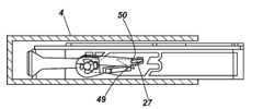
래치 트랙(28)은 고정 트랙(28A) 및 해제 트랙(28B)을 포함한다. 고정 트랙(28A)은 해제 트랙(28B)과 전체적으로 상이할 수도 있고, 또는 부분적으로 상이할 수도 있다. 래치 스톱(30)은 고정 트랙(28A)과 해제 트랙(28B) 사이에 배치되어, 삽입 동안에는 래치(27)가 래치 스톱(30)의 일측면(28A)에서 안내되고, 방출 시에는 반대쪽 측면(28B)에서 안내된다. 삽입 시에, 래치(27)는 고정 트랙(28A)에 의해 안내된다. 고정 트랙(28A)은 래치(27)를 래치 스톱(30)의 정확한 측면에서 안내하기 위해 래치 스톱(30)의 래치 안내 표면(46)을 포함할 수 있다. 고정 트랙(28A)은 고정 트랙(28A)의 끝부분에 래치 안내 벽부(47)를 더 포함할 수도 있다. 래치 안내 벽부(47)는, 고정 트랙(28A)의 끝부분에서 래치(27)를 수용하고, 래치(27)를 래치 스톱(30)쪽으로 향하도록 배치된다. 래치 스톱(30)은 래치 스톱 벽부(49) 및 래치 맞닿음부(latch abutment)(50)를 포함한다. 래치 안내 벽부(47)는 래치(27)를 래치 스톱 벽부(49)(도 13)와의 결합 고정 위치로 안내하도록 배치된다. 맞닿음부(50)는 래치(27)가 래치 스톱 벽부(49)에서 미끄러져 나가는 것을 방지하기 위해 래치 스톱 벽부(49)에 돌출부를 포함한다. 고정된 위치에서, 래치(27)는 맞닿음부(50)와 결합한다. 고정된 위치에서는, 이젝터(31)는 압박되며, 래치 스톱(30)이 래치(27) 쪽으로 푸시되도록 카트리지(3)를 푸시한다.The
더욱이, 해제 트랙(28B)은 래치 방향 전환 벽부(latch re-direct wall)(48)를 포함한다. 래치 방향 전환 벽부(48)는, 래치 스톱(30) 및 래치 트랙(28A)이 안쪽으로 푸시될 때에 래치(27)를 수용하고, 래치(27)를 방출을 위해 해제 트랙(28B) 내로 안내하여 래치 스톱 결합 위치에서 벗어나게 하도록 배치된다. 방출 시에, 래치(27)는 삽입과는 반대로 래치 스톱(30)의 반대 측면을 통과한다. 래치 방향 전환 벽부(48)는 래치 트랙(28)의 끝부분에 배치될 수도 있다. 래치(27)가 해제 위치에 있을 때, 이젝터(31)는 카트리지(3)가 수동으로 취출될 수 있도록 카트리지(3)를 방출한다.Furthermore, the
실시예에서, 래치 트랙(28)은 가청 피드백 부재(audible feedback member) 및/또는 촉각 피드백 부재(tactile feedback member)를 포함한다. 래치(27)는 그 피봇축을 중심으로 바이어스될 수 있다. 래치(27)는 래치 트랙(28)을 통해 주행하는 동안 래치 트랙 벽부쪽으로 슬라이드할 수 있다. 예컨대, 하나 이상의 래치 트랙 벽부는 래치(27)가 래치 트랙(28)을 주행하는 동안 가청 피드백 및/또는 촉각 피드백을 제공하기 위해 렛지(ledge)와 같은 하나 이상의 피드백 부재를 포함할 수 있다. 피드백 부재는 래치 안내 벽부(47) 가까이에 제공될 수 있으며, 카트리지(3)가 해방되는 경우, 이곳으로부터 래치(27)가 고정 위치로 이동할 것이다. 가청 피드백 및/또는 촉각 피드백을 수신할 때, 사용자는 카트리지(3)가 해방될 수 있고 수용 구조물(4)에 고정된다는 것을 알게 될 것이다. 카트리지(3)의 해제를 나타내기 위해 래치 방향 전환 벽부(48) 가까이에 또 다른 피드백 부재가 제공될 수도 있다.In an embodiment, the
도 7은 유체 카트리지(3)와 수용 구조물(4)이 연결된 상태에서의 유체 방출 시스템(1)의 일부분에 대한 단면도를 도시하고 있다. 이젝터(31)는 압박되고, 카트리지 래치 스톱(30)을 래치(27) 쪽으로 푸시한다. 카트리지(3)는 가이드(17)에 의해 제위치에 더 확고하게 유지된다. 펜(12, 13)은 카트리지(3)와 유체 방출 장치(2) 간의 각각의 유체의 운송을 위해 각각의 소켓(14, 15) 내에서 크게 연장한다.7 shows a cross-sectional view of a portion of the
컨넥터 회로(18) 및 카트리지 전기 회로(19)의 전극(20, 38)은 각각 측방으로 상호 접속한다. 예컨대, 전극(20, 38)은 Z축에 평행을 이루는 라인 P 또는 PP을 따라 및/또는 Y축과 Z축에 의해 형성된 평면에 평행을 이루는 평면에서 상호 접속한다. 카트리지 전기 회로(19)가 카트리지(3)의 전면(33)에 대해 안쪽으로 함몰되어 있으므로, 컨넥터 회로(18)와 카트리지 전기 회로(19)는 전면(33) 뒤쪽에서 카트리지(3)의 외주 내에서 상호 접속한다. 설치된 상태에서, 컨넥터 회로(18)는 적어도 부분적으로 카트리지(3) 내에서 연장한다. 실시예에서, 컨넥터 회로(18)와 카트리지 전기 회로(19) 간의 접속은 카트리지(3) 내에서 카트리지 키잉 인터페이스(24)의 뒤쪽에 및/또는 카트리지 키잉 인터페이스(24) 다음에 구축된다.The
실시예에서, 카트리지(3)는 예컨대 카트리지(3)를 삽입하거나 취출할 때에 카트리지(3)의 수동 핸들링을 용이하게 하고 이러한 수동 핸들링을 나타내기 위해 적어도 하나의 핑거 결합면(finger engagement surface)(51)을 포함한다. 핑거 결합면(51)은 내향 곡선부(inwards curve), 하나 이상의 리브(rib), 절결부 등 중의 하나 또는 조합을 포함할 수 있다. 핑거 결합면(51)은 카트리지(3)의 상면(53)에서 후면(34)에 근접하게 배치될 수 있다. 도시된 실시예에 예시된 바와 같이, 카트리지(3)가 설치된 상태에서, 수용 구조물(4)은 핑거 결합면(51)을 거의 대부분을 덮게 된다. 방출 후, 핑거 결합면(51)이 눈에 보이게 되고, 카트리지(3)의 취출을 위해 결합이 자유롭게 된다.In an embodiment, the
실시예에서, 카트리지(3)는 카트리지(3)의 고정 및 해제를 위해 카트리지(3)를 수용 구조물(4) 내로 푸시할 필요가 있다는 것을 나타내기 위해 핑거 푸시면(finger push surface)(52)을 포함한다. 핑거 푸시면(52)은 내향 곡선부, 하나 이상의 리브, 절결부 등 중의 하나 또는 조합을 포함할 수 있다. 핑거 푸시면(52)은 후면(34)에 배치된다. 카트리지(3)가 설치된 상태에서, 후면(34) 및 핑거 푸시면(52)은 수용 구조물(4)의 바깥쪽에서 눈에 보이도록 되어 있다. 핑거 푸시면(52)이 후면(34) 상의 미리 정해진 위치를 가질 수 있지만, 이 부분의 특정 실시예의 특징은, 가이드(17)가 특정한 푸싱 위치 또는 기울기에 상관없이 직선 Y를 따라 카트리지(3)를 안내할 수 있기 때문에, 카트리지(3)가 인터페이스의 적합한 연결을 위해 후면(33)의 어떠한 위치에서도 푸시될 수 있다는 점에 있다.In an embodiment the
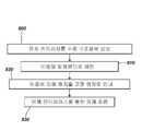
도 8은 유체 카트리지(3)를 수용 구조물(4)에 연결하는 방법의 실시예를 흐름도로 도시하고 있다. 이 방법의 제1 단계(800)에서는, 유체 카트리지(3)를 수용 구조물에 삽입한다. 이동은 일차원으로 제한된다. 즉, 단계 810에 의해 나타낸 바와 같이, 카트리지(3)가 직선 Y를 따라 이동된다. 일차원 이동의 종료 시에, 카트리지(3)와 유체 방출 장치(2) 간의 유체 연결이 구축된다. 단계 820에서는, 래치(27)를 직선 Y를 따른 이동에 의해 고정 위치로 안내한다. 래치(27)는 유체 연결을 유지한다. 단계 810 및 820은 동시에 발생할 수도 있다. 단계 830에서는, 예컨대 유체 방출을 위해, 연결된 유체 인터페이스를 통해 유체가 흐를 수 있게 된다.Fig. 8 is a flow chart showing an embodiment of a method of connecting the
도 9는 유체 카트리지(3)를 수용 구조물(4)에 연결하는 방법의 다른 실시예를 흐름도로 도시하고 있다. 도 10 내지 도 15는, 도 9의 단계(900∼914)의 일부에 대응하는, 래치 구성(26)에 대한 카트리지(3)의 순차적인 위치를 예시한다.9 shows a flow chart of another embodiment of a method of connecting the
단계 900에서는, 카트리지(3)를 수용 구조물(4)에 수동으로 삽입한다. 도 10은 단계 900에 대응하며, 수용 구조물(4) 및 래치 구성(26)에 대한 카트리지(3)의 위치가 도시되어 있다. 다음 단계 901에서는, 가이드 트랙(21)이 가이드(17)와 결합한다. 카트리지(3)를 수용 구조물(4) 내로 더 깊게 푸싱함으로써, 가이드(17)가 이젝터(31)의 방향으로 직선 Y를 따라 카트리지(3)를 안내한다. 그 다음 단계 902에서, 래치(27)가 래치 트랙(28)과 결합한다. 래치(27)는 도 11에 예시된 바와 같이 고정 트랙(28A)을 따라 안내된다. 피봇 아암(29B)이 피봇축 L(도 3)을 중심으로 피봇하여, 래치(27)가 고정 트랙(28A)의 벽부에 의해 안내되도록 할 수 있다. 단계 903에서는, 이젝터(31)가 카트리지의 전면(33)과 결합하고, 압박된다. 이젝터(31)는 제2 펜 수용 소켓(15) 주위에 제공되는 링(36)과 결합할 수 있다. 상기한 단계 901 내지 903은 동시에 발생할 수도 있다.In
도 9 내지 도 15에 도시된 실시예에서, 카트리지(3) 및 수용 구조물(4)은 부합하는 키잉 인터페이스(22, 24)를 갖는다. 단계 904에서는, 유체 인터페이스(12, 13, 14, 15)가 상호 연결되고, 수용 구조물(4)과 카트리지(3)의 키잉 인터페이스(22, 24)가 부합한다. 부합하는 키잉 인터페이스(22, 24)는 카트리지 전기 회로(19)와 컨넥터 회로(18)가 상호 접속할 수 있도록 한다. 키가 부합한 후, 단계 905에서는, 회로(18, 19) 간의 전기 접속이 구축된다. 제어 회로(8)는 전기 접속이 구축되었다는 대응하는 신호를 수신한다. 구축된 전기 접속은 유체 연결 또한 구축되었다는 것을 암시한다.In the embodiment shown in Figures 9-15, the
단계 906에서는, 촉각 피드백 및/또는 가청 피드백을 수신할 때까지 사용자가 카트리지(3)를 푸시한다. 예컨대, 래치(27)는 래치 트랙(28)의 끝부분(47)과 결합하고, 및/또는 가이드 스톱(45)이 가이드(17)의 끝부분과 결합하고, 및/또는 이젝터(33)가 더 이상 압박될 수 없다. 대응하는 도 12에서, 래치(27)가 래치 트랙(28)의 끝부분과 결합하는 것으로 도시되어 있으며, 이 실시예에서는 래치(27)가 래치를 해방 시에 고정 위치로 향하게 하기 위해 래치 안내 벽부(47)와 결합한다. 단계 907에서는, 사용자가 카트리지(3)를 수동으로 해방한다. 단계 908에서는, 이젝터(31)가 비압박되어, 래치(27)가 래치 스톱(30)과 결합할 때까지 카트리지(33)를 뒤쪽으로 푸시한다. 대응하는 도 13으로부터 알 수 있는 바와 같이, 래치(27)는 래치 스톱 벽부(49)와 결합함으로써 카트리지(3)를 유지한다. 래치(27)는 맞닿음부(50)에 의해 제위치에 유지된다. 키 부합 및 전기 접속에 대한 단계인 단계 904 및 905와, 래치 고정의 단계인 단계 906 내지 908은 대략적으로 동시에 발생할 수도 있다.In
카트리지(3)가 정확하게 푸시되지 않으면, 유체 인터페이스 및/또는 기타 인터페이스가 적합하게 연결되지 않을 수도 있다. 이러한 경우, 래치(27)가 래치 안내 벽부(47)에 도달하지 않을 수도 있으며, 고정 위치에 도달하지 않는다. 그러므로, 어떠한 전기 접속 및/또는 유체 연결이 이루어지기 전에, 카트리지(3)가 이젝터(31)에 의해 자동으로 밖으로 푸시될 것이다.If the
단계 909에서는, 유체 방출 시스템(1)이 제1 유체 인터페이스(12, 14)를 통해 카트리지(3)로부터 제1 유체를 수령함으로써 인쇄한다. 인쇄 후, 예컨대 카트리지(3)가 실질적으로 빈 상태로 될 때, 카트리지(3)는 교체를 위해 방출될 수 있다. 단계 910에서는, 사용자가 카트리지(3)를 이젝터(31)의 방향으로 푸시한다. 카트리지(3)를 푸시함으로써, 래치(27)가 래치 방향 전환 벽부(48)와 결합할 수 있다. 다음 단계인 단계 911에서는, 래치(27)가 예컨대 래치 방향 전환 벽부(48)에 의해 해제 위치로 안내된다(도 14). 해제 위치에서, 카트리지(3)는 래치(27)에 의해 더 이상 유지되지 않는다. 단계 912에서는, 사용자가 카트리지(3)를 수동으로 해방시킬 수 있다. 단계 913에서는, 이젝터(31)가 비압박되어 카트리지(3)를 방출한다(도 15). 방출은 카트리지(3)가 더 이상 유지되지 않는 이후에 가능하게 된다(도 15). 단계 914에서는, 사용자가 카트리지(3)를 수용 구조물(4) 밖으로 취출한다.In
전술한 바와 같이, 카트리지(3)는 제1 유체 인터페이스(12), 제2 유체 인터페이스(13), 전기 인터페이스(19), 이젝터 정렬 인터페이스(36), 및/또는 키잉 인터페이스(24)를 포함할 수 있으며, 이들은 전면(33)에 배치된다. 가이드 인터페이스는 전면(33) 가까이에 수용 개구부(40)를 갖는 바닥면(35)에 배치된다. 그러므로, 인터페이스들은 카트리지(3)의 전면(33) 가까이에서 결합하도록 배치된다. 도시된 실시예에서, 키잉 인터페이스(24) 및 전기 인터페이스(19)는 상면(53) 가까이에 배치되고, 제2 유체 인터페이스(15) 및 이젝터 정렬 인터페이스(36)는 전면(33)의 중앙 가까이에 배치되며, 제1 유체 인터페이스(14) 및 가이드 수용 개구부(40)는 바닥면(35) 가까이에 배치된다. 이들 인터페이스는 전면(33)에 걸쳐 비교적 고르게 분포되어, 각각의 인터페이스의 연결력의 비교적 고른 분포와, 예컨대 대략 14N 이하의 비교적 낮은 총연결력을 제공한다. 유체 방출 시스템(1)의 래치 및 가이드 기구에서, 래치 또는 가이드 부분의 변형이 필수적이지 않다. 비교적 약하고 간편한 푸시에 의해서도 안전한 고정을 달성하기에 충분하다. 더욱이, 가이드(17)는 사용자가 하나의 방향 Y에서의 모든 연결을 구축하기 위해 카트리지(3)의 후면(34)의 어떠한 위치에서도 푸시할 수 있도록 한다.As described above, the
카트리지(3) 및 수용 구조물(4)은 비교적 얇아서 프린터의 적은 부피만을 차지할 수 있다. 카트리지 이동 트랙 또한 직선 Y로 구성되기 때문에 공간을 거의 차지하지 않는다. 더욱이, 카트리지(3)는 동일한 방향 Y으로의 동일한 푸시 동작을 이용하여 해방될 수 있다. 카트리지(3)가 예컨대 유동적으로 및/또는 전기적으로 적합하게 연결되지 않으면, 카트리지(3)는 이젝터(31)에 의해 자동으로 밖으로 푸시된다.The
전술한 설명은 본 발명을 본 명세서에 개시된 실시예로 국한하거나 제한하려는 것이 아니다. 도면, 상세한 설명 및 첨부된 청구범위에 대한 이해를 통하여 청구 발명을 실시함에 있어서 당업자에 의하여 개시된 실시예에 대한 기타 변형이 이루어질 수 있다. 일부 실시예에서, 도시된 실시예에 대하여 기계적 자리바꿈(mechanical inversion)이 적용될 수도 있다. 예컨대, 래치 트랙(28)이 수용 구조물(4)에 제공되는 한편, 래치 구성(26)이 카트리지(3)에 제공되어도 된다. 카트리지(3)의 제1 및 제2 유체 인터페이스가 펜을 포함하는 한편, 수용 구조물(4)의 대응하는 제1 및 제2 유체 인터페이스가 소켓을 포함하여도 된다.The foregoing description is not intended to limit or limit the invention to the embodiments disclosed herein. Other variations on the embodiments disclosed by those skilled in the art in carrying out the claimed invention may be made through the drawings, the description and the appended claims. In some embodiments, mechanical inversion may be applied to the illustrated embodiment. For example, a
본 명세서에서 어떠한 요소를 단수로 표현하였어도 그 요소가 복수 개로 존재하는 것을 배제하는 것은 아니며, 어떠한 요소를 특정의 개수로 표현하였어도 그 요소가 그보다 많은 개수로 존재할 가능성을 배제하는 것은 아니다. 본 발명에서 언급된 여러 항목의 기능을 단일 유닛으로 수행할 수도 있으며, 그 반대로 하나의 유닛의 기능을 여러 개의 항목이 수행할 수도 있다.It is not intended to exclude the presence of a plurality of elements in the specification, and does not exclude the possibility that the elements may be present in a larger number even if they are expressed by a specific number. The functions of the various items mentioned in the present invention may be performed by a single unit, and conversely, the functions of one unit may be performed by several items.
Claims (8)
Translated fromKorean카트리지 수용 구조물(4)에 대한 연결을 위해 전면(33) 상에 있는 인터페이스들 - 상기 인터페이스들은 바닥면(35) 가까이에 잉크 소켓(14)을 가지는 인터페이스와 공기 펜을 수용하는 기체 소켓(15)을 가지는 인터페이스를 포함함 -;
상기 인터페이스들의 연결을 위해 상기 잉크 카트리지(3)를 직선(Y)을 따라 안내하고, 상기 전면(33)과 상기 바닥면(35) 사이의 연결부에 배열된 가이드 수용 개구부(40)를 포함하는 가이드 인터페이스;
상기 카트리지 수용 구조물(4)의 래치(27)를 안내하고 유지하기 위해 상기 바닥면(35)에 배치되는 래치 스톱(30) 및 래치 트랙(28); 및
카트리지 특성 데이터를 포함하는 메모리(11)를 가지고, 상기 전면(33)에 연결되는 상면(53) 가까이에 배치되는 전기 회로(10, 19)로서, 상기 상면(53)은 상기 바닥면(35)에 대향하면서 평행한, 전기 회로(10, 19)
를 포함하고,
상기 전기 회로(10, 19)는,
상기 전면(33) 가까이에 배치되고, 상기 전면(33) 뒤에 연장되고, 상기 전면(33)에 대하여 움푹 들어가 있어서, 다른 인터페이스가 연결된 후에 전기 접촉을 구축하고,
상기 전면(33)에 수직인 평면(Y, Z)에 연장되고 상기 전면(33) 뒤쪽에서 상기 전면(33)에 평행을 이루는 라인(PP) 상에 배열되는 전극을 포함하고,
상기 가이드 수용 개구부(40), 상기 잉크 소켓(14), 상기 기체 소켓(15) 및 상기 전기 회로(10, 19)는 상기 전면(33)의 하부로부터 상기 잉크 카트리지(3)의 높이의 방향에 따라 순서대로 배열되고,
상기 전면(33) 상의 인터페이스들은 상기 전면(33)의 중앙 가까이에 배치되는 이젝터 정렬 인터페이스(36)을 포함하고, 상기 이젝터 정렬 인터페이스(36)는 링 형상의 릿지(ring-shaped ridge)를 포함하고,
상기 링 형상의 릿지는, 각 소켓과 동일한 중심축(C2)을 가지고 상기 전면(33)에 있는 기체 소켓(15) 주위에 배치되어, 상기 기체 소켓(15)이 상기 공기 펜을 수용할 때 상기 이젝터 정렬 인터페이스(36)가 상기 공기 펜의 베이스에 부착된 스프링 형상의 이젝터(31)를 정렬시키고 제위치에 유지하도록 하는, 잉크젯 프린터용 잉크 카트리지.An ink cartridge (3) for an inkjet printer (2)
Interfaces on the front surface 33 for connection to the cartridge receiving structure 4-the interfaces are provided with an interface with the ink receptacle 14 near the bottom surface 35 and a gas receptacle 15 for receiving the air pen, - an interface having an interface;
(40) for guiding the ink cartridge (3) along a straight line (Y) for connection of the interfaces and arranged at a connection between the front surface (33) and the bottom surface (35) interface;
A latch stop (30) and a latch track (28) disposed on the bottom surface (35) for guiding and holding the latch (27) of the cartridge receiving structure (4); And
An electrical circuit (10, 19) having a memory (11) containing cartridge characteristic data and arranged near an upper surface (53) connected to said front surface (33), said upper surface (53) The electric circuits 10 and 19, which are parallel and opposite to each other,
Lt; / RTI >
The electric circuit (10, 19)
Is disposed near the front surface (33), extends behind the front surface (33), and is recessed with respect to the front surface (33), establishing electrical contact after the other interface is connected,
And electrodes arranged on a line (PP) extending in a plane (Y, Z) perpendicular to the front surface (33) and parallel to the front surface (33) behind the front surface (33)
The guide receptacle opening 40, the ink receptacle 14, the gasket 15 and the electric circuit 10 and 19 are arranged in the direction of the height of the ink cartridge 3 from below the front surface 33 Are arranged in order,
The interface on the front side 33 includes an ejector alignment interface 36 disposed proximate the center of the front side 33 and the ejector alignment interface 36 includes a ring-shaped ridge ,
The ring-shaped ridge is arranged around the gasket 15 in the front surface 33 with the same central axis C2 as the respective socket so that when the gasket 15 receives the air pen, The ejector alignment interface (36) aligns and keeps the spring-shaped ejector (31) attached to the base of the air pen in place.
상기 전기 회로(10, 19)는 상기 카트리지(3)의 외주 내에서 대응하는 커넥터 회로(18)와 측방(X, B) 연결을 구축하는, 잉크젯 프린터용 잉크 카트리지.The method according to claim 1,
Wherein said electrical circuit (10, 19) establishes lateral (X, B) connection with a corresponding connector circuit (18) within the periphery of said cartridge (3).
상기 잉크 소켓(14)이 상기 카트리지 수용 구조물(4)의 원뿔대 형상인 펜을 수용하기 위한 밀봉 링(37)을 포함하고, 상기 밀봉 링(37)은 펜을 삽입시 펜의 원뿔대 형상을 따라 둘러싸고 밀봉하기 위해 적어도 대략 0.6mm가 늘어나게 되는 내경을 가지는, 잉크젯 프린터용 잉크 카트리지.The method according to claim 1,
Wherein the ink receptacle (14) includes a sealing ring (37) for receiving a pen in the frustum shape of the cartridge receiving structure (4), the sealing ring (37) surrounding the pen- And has an inner diameter that is at least about 0.6 mm to be extended for sealing.
상기 가이드 인터페이스(17)는 상기 직선에 평행하게 연장되는 가이드 트랙(21)을 포함하는, 잉크젯 프린터용 잉크 카트리지.The method according to claim 1,
Wherein the guide interface (17) comprises a guide track (21) extending parallel to the straight line.
상기 가이드 트랙(21)은 상기 카트리지 수용 구조물(4)의 대응하는 T-레일(17)을 안내하기 위한 T자형 절결부를 포함하는, 잉크젯 프린터용 잉크 카트리지.The method according to claim 6,
Wherein the guide track (21) comprises a T-shaped cutout for guiding a corresponding T-rail (17) of the cartridge receiving structure (4).
상기 가이드 트랙(21) 및 상기 래치 트랙(28)이 상기 카트리지(3)의 바닥면(35)에 하나의 일체의 절결부에 의해 형성되는, 잉크젯 프린터용 잉크 카트리지.The method according to claim 6,
Wherein the guide track (21) and the latch track (28) are formed by one integral cutout on the bottom surface (35) of the cartridge (3).
Applications Claiming Priority (1)
| Application Number | Priority Date | Filing Date | Title |
|---|---|---|---|
| PCT/US2010/053692WO2012054050A1 (en) | 2010-10-22 | 2010-10-22 | Fluid cartridge |
Related Parent Applications (1)
| Application Number | Title | Priority Date | Filing Date |
|---|---|---|---|
| KR1020177004698ADivisionKR101870852B1 (en) | 2010-10-22 | 2010-10-22 | Fluid cartridge |
Publications (2)
| Publication Number | Publication Date |
|---|---|
| KR20180069116A KR20180069116A (en) | 2018-06-22 |
| KR101987723B1true KR101987723B1 (en) | 2019-06-11 |
Family
ID=44630134
Family Applications (5)
| Application Number | Title | Priority Date | Filing Date |
|---|---|---|---|
| KR1020177010802AActiveKR101826937B1 (en) | 2010-10-22 | 2010-10-22 | Fluid cartridge |
| KR1020147017271AExpired - Fee RelatedKR101729592B1 (en) | 2010-10-22 | 2010-10-22 | Fluid cartridge |
| KR1020177004698AExpired - Fee RelatedKR101870852B1 (en) | 2010-10-22 | 2010-10-22 | Fluid cartridge |
| KR1020137013125ACeasedKR20140009205A (en) | 2010-10-22 | 2010-10-22 | Fluid cartridge |
| KR1020187016736AActiveKR101987723B1 (en) | 2010-10-22 | 2010-10-22 | Fluid cartridge |
Family Applications Before (4)
| Application Number | Title | Priority Date | Filing Date |
|---|---|---|---|
| KR1020177010802AActiveKR101826937B1 (en) | 2010-10-22 | 2010-10-22 | Fluid cartridge |
| KR1020147017271AExpired - Fee RelatedKR101729592B1 (en) | 2010-10-22 | 2010-10-22 | Fluid cartridge |
| KR1020177004698AExpired - Fee RelatedKR101870852B1 (en) | 2010-10-22 | 2010-10-22 | Fluid cartridge |
| KR1020137013125ACeasedKR20140009205A (en) | 2010-10-22 | 2010-10-22 | Fluid cartridge |
Country Status (26)
| Country | Link |
|---|---|
| US (2) | US8882252B2 (en) |
| EP (10) | EP3034303B1 (en) |
| JP (1) | JP5688156B2 (en) |
| KR (5) | KR101826937B1 (en) |
| CN (2) | CN103153626B (en) |
| AR (1) | AR083524A1 (en) |
| AU (1) | AU2010362693B2 (en) |
| BR (1) | BR112013009626B1 (en) |
| CA (1) | CA2813381C (en) |
| CL (1) | CL2013000666A1 (en) |
| DK (5) | DK2740604T3 (en) |
| ES (9) | ES2752226T3 (en) |
| HR (1) | HRP20150501T4 (en) |
| HU (3) | HUE047378T2 (en) |
| IL (1) | IL225158A (en) |
| MX (1) | MX2013003254A (en) |
| MY (1) | MY161588A (en) |
| NO (1) | NO2588320T3 (en) |
| PH (1) | PH12013500670A1 (en) |
| PL (9) | PL2628598T3 (en) |
| PT (6) | PT2588320E (en) |
| RU (3) | RU2546494C2 (en) |
| SG (1) | SG189281A1 (en) |
| SI (1) | SI2588320T1 (en) |
| TW (3) | TWI532603B (en) |
| WO (2) | WO2012054050A1 (en) |
Families Citing this family (51)
| Publication number | Priority date | Publication date | Assignee | Title |
|---|---|---|---|---|
| ES2752226T3 (en)* | 2010-10-22 | 2020-04-03 | Hewlett Packard Development Co | Fluid cartridge |
| US8651643B2 (en) | 2010-10-22 | 2014-02-18 | Hewlett-Packard Development Company, L.P. | Fluid cartridge |
| JP6136247B2 (en)* | 2012-12-25 | 2017-05-31 | セイコーエプソン株式会社 | Liquid container holding device and liquid ejecting device |
| EP2968808B1 (en) | 2013-03-14 | 2019-06-05 | Fisher & Paykel Healthcare Limited | Catheter mount with suction port |
| JP6210268B2 (en)* | 2013-03-27 | 2017-10-11 | セイコーエプソン株式会社 | Printing device |
| JP6476551B2 (en)* | 2013-05-15 | 2019-03-06 | セイコーエプソン株式会社 | Cartridge and printing material supply system |
| JP5960345B2 (en) | 2013-09-18 | 2016-08-02 | キヤノン株式会社 | Ink cartridge and inkjet printer |
| DE112014004288T5 (en) | 2013-09-18 | 2016-06-09 | Canon Kabushiki Kaisha | Ink cartridge and inkjet printer |
| US9152083B2 (en)* | 2013-10-09 | 2015-10-06 | Lexmark International, Inc. | Carriage assembly for toner cartridge loading and latching |
| US9280087B2 (en) | 2013-11-20 | 2016-03-08 | Lexmark International, Inc. | Electrophotographic image forming device latching system for retaining a replaceable unit |
| US9261851B2 (en) | 2013-11-20 | 2016-02-16 | Lexmark International, Inc. | Positional control features of a replaceable unit for an electrophotographic image forming device |
| BR112016024662B1 (en)* | 2014-04-22 | 2022-02-01 | Hewlett-Packard Development Company, L.P | Fluid flow structure and print head |
| JP6494352B2 (en) | 2014-05-30 | 2019-04-03 | キヤノン株式会社 | Liquid discharge head |
| JP6562691B2 (en)* | 2014-05-30 | 2019-08-21 | キヤノン株式会社 | Liquid discharge head |
| JP6562694B2 (en) | 2014-05-30 | 2019-08-21 | キヤノン株式会社 | Liquid discharge head, liquid discharge apparatus, and method for electrically connecting liquid discharge head and liquid storage container |
| US9285758B1 (en) | 2014-12-19 | 2016-03-15 | Lexmark International, Inc. | Positional control features between replaceable units of an electrophotographic image forming device |
| US9291992B1 (en) | 2014-12-19 | 2016-03-22 | Lexmark International, Inc. | Positional control features for an imaging unit in an electrophotographic image forming device |
| JP6424704B2 (en) | 2015-03-27 | 2018-11-21 | ブラザー工業株式会社 | Liquid cartridge |
| JP6435957B2 (en) | 2015-03-27 | 2018-12-12 | ブラザー工業株式会社 | Liquid cartridge |
| JP6447300B2 (en) | 2015-03-27 | 2019-01-09 | ブラザー工業株式会社 | Liquid cartridge |
| JP6447299B2 (en) | 2015-03-27 | 2019-01-09 | ブラザー工業株式会社 | Liquid cartridge |
| JP6413881B2 (en) | 2015-03-27 | 2018-10-31 | ブラザー工業株式会社 | Liquid cartridge |
| US9411303B1 (en) | 2015-04-10 | 2016-08-09 | Lexmark International, Inc. | Positioning stop assembly for a replaceable unit of an electrophotographic image forming device |
| CA2990341C (en)* | 2015-07-07 | 2020-07-21 | Brother Kogyo Kabushiki Kaisha | Liquid cartridge, liquid consuming apparatus, method of inserting liquid cartridge into cartridge mounting portion of liquid consuming apparatus, and use of liquid cartridge |
| WO2017006365A1 (en)* | 2015-07-07 | 2017-01-12 | Brother Kogyo Kabushiki Kaisha | Liquid cartridge, liquid consuming apparatus, method of inserting liquid cartridge into cartridge mounting portion of liquid consuming apparatus, and use of liquid cartridge |
| CA2990350C (en)* | 2015-07-07 | 2020-07-14 | Brother Kogyo Kabushiki Kaisha | Liquid cartridge, liquid consuming apparatus, method of inserting liquid cartridge into cartridge mounting portion of liquid consuming apparatus, and use of liquid cartridge |
| US20210291540A1 (en)* | 2016-07-27 | 2021-09-23 | Hewlett-Packard Development Company, L.P. | Vertical interface for fluid supply cartridge having digital fluid level sensor |
| EP3300904B1 (en)* | 2016-09-30 | 2021-09-01 | Seiko Epson Corporation | Cartridge and connector |
| KR102137173B1 (en)* | 2018-06-15 | 2020-07-24 | 엘지전자 주식회사 | Guidance robot |
| KR102447092B1 (en) | 2018-07-13 | 2022-09-23 | 휴렛-팩커드 디벨롭먼트 컴퍼니, 엘.피. | printing liquid supply |
| EP3687807B1 (en) | 2018-07-13 | 2022-12-21 | Hewlett-Packard Development Company, L.P. | Print liquid supply |
| PT3612395T (en) | 2018-07-13 | 2021-02-04 | Hewlett Packard Development Co | Print liquid supply |
| MX2020010362A (en) | 2018-07-13 | 2020-10-19 | Hewlett Packard Development Co | Print liquid supply. |
| RU2751584C1 (en) | 2018-07-13 | 2021-07-15 | Хьюлетт-Паккард Дивелопмент Компани, Л.П. | Device for supplying printing liquid |
| FR3086575B1 (en)* | 2018-09-28 | 2022-09-30 | Ivy Group Holding | INKJET PRINTING MODULE FOR A PRINTING ROBOT, STORE FOR SUCH MODULES, AND INKJET PRINTING METHOD USING THIS ROBOT |
| WO2020117322A1 (en)* | 2018-12-03 | 2020-06-11 | Hewlett-Packard Development Company, L.P. | Print liquid supply units |
| ES2848998T3 (en) | 2018-12-03 | 2021-08-13 | Hewlett Packard Development Co | Logic circuits |
| US11338586B2 (en) | 2018-12-03 | 2022-05-24 | Hewlett-Packard Development Company, L.P. | Logic circuitry |
| CN113165391A (en) | 2018-12-03 | 2021-07-23 | 惠普发展公司,有限责任合伙企业 | Logic circuit |
| KR20210087502A (en) | 2018-12-03 | 2021-07-12 | 휴렛-팩커드 디벨롭먼트 컴퍼니, 엘.피. | logic circuit |
| EP3687797A1 (en) | 2018-12-03 | 2020-08-05 | Hewlett-Packard Development Company, L.P. | Logic circuitry |
| PL3688636T3 (en) | 2018-12-03 | 2023-09-11 | Hewlett-Packard Development Company, L.P. | Logic circuitry |
| EP4108464B1 (en) | 2018-12-03 | 2023-10-04 | Hewlett-Packard Development Company, L.P. | Printable liquid supply cartridges |
| WO2021080607A1 (en) | 2019-10-25 | 2021-04-29 | Hewlett-Packard Development Company, L.P. | Logic circuitry package |
| US10894423B2 (en) | 2018-12-03 | 2021-01-19 | Hewlett-Packard Development Company, L.P. | Logic circuitry |
| US11366913B2 (en) | 2018-12-03 | 2022-06-21 | Hewlett-Packard Development Company, L.P. | Logic circuitry |
| AU2018452257B2 (en) | 2018-12-03 | 2022-12-01 | Hewlett-Packard Development Company, L.P. | Logic circuitry |
| CN113168446A (en) | 2018-12-03 | 2021-07-23 | 惠普发展公司,有限责任合伙企业 | Logic circuitry packaging |
| EP4031997A1 (en) | 2020-04-30 | 2022-07-27 | Hewlett-Packard Development Company, L.P. | Logic circuitry package for print apparatus |
| JP2023149374A (en) | 2022-03-31 | 2023-10-13 | ブラザー工業株式会社 | Liquid cartridge and liquid supply system |
| CN118372556A (en)* | 2024-05-16 | 2024-07-23 | 珠海纳思达企业管理有限公司 | A consumables box |
Citations (6)
| Publication number | Priority date | Publication date | Assignee | Title |
|---|---|---|---|---|
| JP2006513060A (en)* | 2003-01-14 | 2006-04-20 | プリント−ライト ユニコーン イマージ プロダクツ カンパニー リミテッド オヴ ズーハイ | Seal ring and ink cartridge provided with seal ring |
| JP2007136980A (en)* | 2005-11-22 | 2007-06-07 | Seiko Epson Corp | Ink pack |
| CN101143519A (en)* | 2002-06-17 | 2008-03-19 | 精工爱普生株式会社 | Inkjet recording device and ink cartridge |
| JP2010000671A (en)* | 2008-06-19 | 2010-01-07 | Ricoh Co Ltd | Ink cartridge and image forming device |
| WO2013105504A1 (en)* | 2012-01-13 | 2013-07-18 | セイコーエプソン株式会社 | Cartridge, printing material supply system, printing device, liquid storage container, printing system, and terminal connection structure |
| JP2013163364A (en)* | 2012-01-12 | 2013-08-22 | Seiko Epson Corp | Cartridge and printing material supply system |
Family Cites Families (57)
| Publication number | Priority date | Publication date | Assignee | Title |
|---|---|---|---|---|
| US3697103A (en) | 1970-11-03 | 1972-10-10 | Defense Australia | Telescopic tube locking and unlocking system |
| US5273328A (en) | 1990-09-27 | 1993-12-28 | Nifco Inc. | Lock mechanism and latch device |
| EP0715959B1 (en)* | 1991-12-11 | 1999-06-30 | Canon Kabushiki Kaisha | Ink jet cartridge and ink tank |
| JP3109714B2 (en)* | 1994-12-16 | 2000-11-20 | 船井電機株式会社 | Ink cartridge exchange mechanism |
| US6142617A (en) | 1995-04-27 | 2000-11-07 | Hewlett-Packard Company | Ink container configured for use with compact supply station |
| US6203147B1 (en)* | 1994-12-22 | 2001-03-20 | Hewlett-Packard Company | Electrical and fluidic interface for an ink supply |
| US5699091A (en)* | 1994-12-22 | 1997-12-16 | Hewlett-Packard Company | Replaceable part with integral memory for usage, calibration and other data |
| JP3158915B2 (en)* | 1994-12-27 | 2001-04-23 | ブラザー工業株式会社 | Mobile ink ejection device |
| US7114801B2 (en)* | 1995-04-27 | 2006-10-03 | Hewlett-Packard Development Company, L.P. | Method and apparatus for providing ink to an ink jet printing system |
| US6017118A (en)* | 1995-04-27 | 2000-01-25 | Hewlett-Packard Company | High performance ink container with efficient construction |
| JP3295339B2 (en)* | 1996-08-30 | 2002-06-24 | キヤノン株式会社 | Ink tank, holder, inkjet cartridge and cap |
| US7188918B2 (en) | 1997-01-21 | 2007-03-13 | Hewlett-Packard Development Company, L.P. | Ink delivery system adapter |
| US6168262B1 (en)* | 1997-01-30 | 2001-01-02 | Hewlett-Packard Company | Electrical interconnect for replaceable ink containers |
| CN1088012C (en)* | 1997-01-30 | 2002-07-24 | 惠普公司 | Ink container configured for use with compact supply station |
| ES2257507T3 (en)* | 1997-06-04 | 2006-08-01 | Hewlett-Packard Company | ADAPTER FOR INK FEEDING SYSTEM. |
| US5949459A (en)* | 1997-06-04 | 1999-09-07 | Hewlett-Packard Company | Method and apparatus for securing an ink container |
| US6056333A (en)* | 1998-09-08 | 2000-05-02 | Illinois Tool Works Inc. | Floating latch mechanism |
| US6213454B1 (en)* | 1999-03-31 | 2001-04-10 | Illinois Tool Works Inc. | Reverse air damper with latching mechanism |
| US6155678A (en) | 1999-10-06 | 2000-12-05 | Lexmark International, Inc. | Replaceable ink cartridge for ink jet pen |
| CN100439106C (en)* | 2000-01-21 | 2008-12-03 | 精工爱普生株式会社 | Ink cartridge for printing apparatus and ink jet printing apparatus |
| EP1431042B1 (en)* | 2000-01-31 | 2007-11-28 | Hewlett-Packard Company | Replaceable ink container for an inkjet printing system |
| TW505574B (en)* | 2000-01-31 | 2002-10-11 | Hewlett Packard Co | Ink container configured to establish reliable electrical connection with a receiving station |
| US6488369B1 (en)* | 2000-01-31 | 2002-12-03 | Hewlett-Packard Company | Ink container configured to establish reliable electrical and fluidic connections to a receiving station |
| US6375315B1 (en)* | 2000-04-11 | 2002-04-23 | Hewlett-Packard Company | Replaceable ink container for an inkjet printing system |
| JP3387890B2 (en)* | 2000-03-31 | 2003-03-17 | キヤノン株式会社 | Liquid container and recording device |
| PT1199179E (en)* | 2000-10-20 | 2007-02-28 | Seiko Epson Kabushiki Kaisha S | Ink-jet recording device and ink cartridge |
| CA2379725C (en)* | 2001-04-03 | 2007-06-12 | Seiko Epson Corporation | Ink cartridge |
| DE10120435A1 (en) | 2001-04-26 | 2002-10-31 | Fischer Artur Werke Gmbh | Push-push locking mechanism |
| US6471333B1 (en)* | 2001-04-30 | 2002-10-29 | Hewlett-Packard Company | Method and apparatus for keying ink supply containers |
| MXPA03002490A (en)* | 2002-03-20 | 2004-10-15 | Seiko Epson Corp | Ink cartridge and ink cartridge holder. |
| US6655793B2 (en) | 2002-03-26 | 2003-12-02 | Hewlett-Packard Development Company, L.P. | Print cartridge supporting apparatus |
| JP4631253B2 (en) | 2002-06-17 | 2011-02-16 | セイコーエプソン株式会社 | Ink jet recording apparatus and ink cartridge |
| JP2004167795A (en)* | 2002-11-19 | 2004-06-17 | Canon Inc | Liquid storage container |
| JP3624950B2 (en)* | 2002-11-26 | 2005-03-02 | セイコーエプソン株式会社 | ink cartridge |
| US7004564B2 (en) | 2003-07-31 | 2006-02-28 | Hewlett-Packard Development Company, L.P. | Printing-fluid container |
| US6959985B2 (en)* | 2003-07-31 | 2005-11-01 | Hewlett-Packard Development Company, L.P. | Printing-fluid container |
| CN101024342B (en) | 2003-08-08 | 2011-01-26 | 精工爱普生株式会社 | Liquid injection device and liquid container seat thereof |
| EP1504906A3 (en) | 2003-08-08 | 2006-03-08 | Seiko Epson Corporation | Liquid container |
| AR049674A1 (en) | 2003-08-08 | 2006-08-30 | Seiko Epson Corp | LIQUID CONTAINER CONTAINER TO SUPPLY A LIQUID SUCH CONSUMPTION APPLIANCE |
| JP4403560B2 (en)* | 2003-08-29 | 2010-01-27 | セイコーエプソン株式会社 | Liquid ejector |
| US7210771B2 (en)* | 2004-01-08 | 2007-05-01 | Eastman Kodak Company | Ink delivery system with print cartridge, container and reservoir apparatus and method |
| TWI255233B (en)* | 2004-02-09 | 2006-05-21 | Brother Ind Ltd | Ink cartridge |
| JP2006043922A (en)* | 2004-07-30 | 2006-02-16 | Canon Inc | Ink tank, ink tank holder, mounting method of the ink tank, and recording head cartridge |
| KR20080022000A (en) | 2006-09-05 | 2008-03-10 | 삼성전자주식회사 | Ink Tank Mounting Device |
| BRPI0718250A2 (en)* | 2006-11-06 | 2014-01-07 | Seiko Epson Corp | CONTAINER FOR LIQUID |
| TWM313993U (en)* | 2007-01-08 | 2007-06-21 | Lite On Technology Corp | A push-push type tray mechanism |
| US7562972B2 (en)* | 2007-01-30 | 2009-07-21 | Brother Kogyo Kabushiki Kaisha | Ink cartridges having signal blocking portions |
| JP4858191B2 (en)* | 2007-01-30 | 2012-01-18 | ブラザー工業株式会社 | Ink cartridge and cartridge storage device |
| JP4862683B2 (en) | 2007-02-19 | 2012-01-25 | ブラザー工業株式会社 | ink cartridge |
| JP2008213147A (en)* | 2007-02-28 | 2008-09-18 | Brother Ind Ltd | Liquid supply apparatus and image recording apparatus |
| JP4304225B2 (en)* | 2008-02-28 | 2009-07-29 | 株式会社リコー | Ink cartridge and inkjet printer |
| JP4561853B2 (en)* | 2008-03-27 | 2010-10-13 | ブラザー工業株式会社 | Droplet ejection device and liquid cartridge |
| JP2010208038A (en)* | 2009-03-06 | 2010-09-24 | Seiko Epson Corp | Liquid ejector and liquid container |
| US8833912B2 (en) | 2009-05-18 | 2014-09-16 | Hewlett-Packard Development Company, L.P. | Replaceable printing component |
| CN201638968U (en) | 2009-12-03 | 2010-11-17 | 富士康(昆山)电脑接插件有限公司 | electronic card connector |
| JP2012000858A (en)* | 2010-06-17 | 2012-01-05 | Brother Industries Ltd | Ink cartridge |
| ES2752226T3 (en)* | 2010-10-22 | 2020-04-03 | Hewlett Packard Development Co | Fluid cartridge |
- 2010
- 2010-10-22ESES14186874Tpatent/ES2752226T3/enactiveActive
- 2010-10-22PTPT108551276Tpatent/PT2588320E/enunknown
- 2010-10-22PLPL13155245Tpatent/PL2628598T3/enunknown
- 2010-10-22WOPCT/US2010/053692patent/WO2012054050A1/enactiveApplication Filing
- 2010-10-22EPEP15201911.3Apatent/EP3034303B1/enactiveActive
- 2010-10-22SISI201030936Tpatent/SI2588320T1/enunknown
- 2010-10-22PLPL19168802Tpatent/PL3530470T3/enunknown
- 2010-10-22ESES17166344Tpatent/ES2770150T3/enactiveActive
- 2010-10-22PHPH1/2013/500670Apatent/PH12013500670A1/enunknown
- 2010-10-22EPEP19168802.7Apatent/EP3530470B1/enactiveActive
- 2010-10-22PTPT141544205Tpatent/PT2740604E/enunknown
- 2010-10-22KRKR1020177010802Apatent/KR101826937B1/enactiveActive
- 2010-10-22EPEP19168801.9Apatent/EP3530469B1/enactiveActive
- 2010-10-22PTPT131552598Tpatent/PT2633997E/enunknown
- 2010-10-22USUS13/816,695patent/US8882252B2/enactiveActive
- 2010-10-22PTPT171663446Tpatent/PT3225404T/enunknown
- 2010-10-22EPEP13155259.8Apatent/EP2633997B1/enactiveActive
- 2010-10-22BRBR112013009626-8Apatent/BR112013009626B1/ennot_activeIP Right Cessation
- 2010-10-22JPJP2013534884Apatent/JP5688156B2/enactiveActive
- 2010-10-22MXMX2013003254Apatent/MX2013003254A/enactiveIP Right Grant
- 2010-10-22EPEP10855127.6Apatent/EP2588320B3/enactiveActive
- 2010-10-22ESES19168802Tpatent/ES2796624T3/enactiveActive
- 2010-10-22PLPL19168801Tpatent/PL3530469T3/enunknown
- 2010-10-22DKDK14154420.5Tpatent/DK2740604T3/enactive
- 2010-10-22NONO10855127Apatent/NO2588320T3/nounknown
- 2010-10-22ESES19168801Tpatent/ES2796610T3/enactiveActive
- 2010-10-22EPEP14186874.5Apatent/EP2826630B1/enactiveActive
- 2010-10-22ESES10855127.6Tpatent/ES2536717T7/enactiveActive
- 2010-10-22PTPT141868745Tpatent/PT2826630T/enunknown
- 2010-10-22EPEP14154420.5Apatent/EP2740604B1/ennot_activeRevoked
- 2010-10-22PLPL17166344Tpatent/PL3225404T3/enunknown
- 2010-10-22EPEP13155245.7Apatent/EP2628598B1/enactiveActive
- 2010-10-22ESES14154420.5Tpatent/ES2561725T3/enactiveActive
- 2010-10-22DKDK17166344.6Tpatent/DK3225404T3/enactive
- 2010-10-22DKDK13155245.7Tpatent/DK2628598T3/enactive
- 2010-10-22MYMYPI2013001113Apatent/MY161588A/enunknown
- 2010-10-22KRKR1020147017271Apatent/KR101729592B1/ennot_activeExpired - Fee Related
- 2010-10-22RURU2013123281/12Apatent/RU2546494C2/enactive
- 2010-10-22KRKR1020177004698Apatent/KR101870852B1/ennot_activeExpired - Fee Related
- 2010-10-22ESES13155259.8Tpatent/ES2473586T3/enactiveActive
- 2010-10-22KRKR1020137013125Apatent/KR20140009205A/ennot_activeCeased
- 2010-10-22CACA2813381Apatent/CA2813381C/enactiveActive
- 2010-10-22DKDK14186874Tpatent/DK2826630T3/enactive
- 2010-10-22DKDK10855127.6Tpatent/DK2588320T6/enactive
- 2010-10-22AUAU2010362693Apatent/AU2010362693B2/ennot_activeCeased
- 2010-10-22HUHUE17166344Apatent/HUE047378T2/enunknown
- 2010-10-22PLPL13155259Tpatent/PL2633997T3/enunknown
- 2010-10-22HUHUE14186874Apatent/HUE046268T2/enunknown
- 2010-10-22PTPT131552457Tpatent/PT2628598E/enunknown
- 2010-10-22PLPL10855127Tpatent/PL2588320T6/enunknown
- 2010-10-22KRKR1020187016736Apatent/KR101987723B1/enactiveActive
- 2010-10-22SGSG2013025457Apatent/SG189281A1/enunknown
- 2010-10-22ESES13155245.7Tpatent/ES2478273T3/enactiveActive
- 2010-10-22HRHRP20150501TTpatent/HRP20150501T4/enunknown
- 2010-10-22PLPL14154420Tpatent/PL2740604T3/enunknown
- 2010-10-22PLPL14186874Tpatent/PL2826630T3/enunknown
- 2010-10-22EPEP17166344.6Apatent/EP3225404B1/enactiveActive
- 2010-10-22HUHUE14154420Apatent/HUE027454T2/enunknown
- 2010-10-22CNCN201080069743.4Apatent/CN103153626B/enactiveActive
- 2011
- 2011-07-22CNCN201180045847.6Apatent/CN103153628B/ennot_activeExpired - Fee Related
- 2011-07-22PLPL11743402Tpatent/PL2616244T3/enunknown
- 2011-07-22WOPCT/US2011/044943patent/WO2012054112A1/enactiveApplication Filing
- 2011-07-22ESES11743402.7Tpatent/ES2511666T3/enactiveActive
- 2011-07-22EPEP11743402.7Apatent/EP2616244B1/ennot_activeNot-in-force
- 2011-10-21TWTW103140037Apatent/TWI532603B/ennot_activeIP Right Cessation
- 2011-10-21TWTW103122351Apatent/TWI542475B/ennot_activeIP Right Cessation
- 2011-10-21ARARP110103906Apatent/AR083524A1/enactiveIP Right Grant
- 2011-10-21TWTW100138296Apatent/TWI473724B/enactive
- 2013
- 2013-02-12USUS13/765,445patent/US8474960B1/ennot_activeExpired - Fee Related
- 2013-03-11ILIL225158Apatent/IL225158A/enactiveIP Right Grant
- 2013-03-11CLCL2013000666Apatent/CL2013000666A1/enunknown
- 2013-12-27RURU2013158769/12Apatent/RU2542140C1/enactive
- 2014
- 2014-07-08RURU2014127846Apatent/RU2664354C2/enactive
Patent Citations (6)
| Publication number | Priority date | Publication date | Assignee | Title |
|---|---|---|---|---|
| CN101143519A (en)* | 2002-06-17 | 2008-03-19 | 精工爱普生株式会社 | Inkjet recording device and ink cartridge |
| JP2006513060A (en)* | 2003-01-14 | 2006-04-20 | プリント−ライト ユニコーン イマージ プロダクツ カンパニー リミテッド オヴ ズーハイ | Seal ring and ink cartridge provided with seal ring |
| JP2007136980A (en)* | 2005-11-22 | 2007-06-07 | Seiko Epson Corp | Ink pack |
| JP2010000671A (en)* | 2008-06-19 | 2010-01-07 | Ricoh Co Ltd | Ink cartridge and image forming device |
| JP2013163364A (en)* | 2012-01-12 | 2013-08-22 | Seiko Epson Corp | Cartridge and printing material supply system |
| WO2013105504A1 (en)* | 2012-01-13 | 2013-07-18 | セイコーエプソン株式会社 | Cartridge, printing material supply system, printing device, liquid storage container, printing system, and terminal connection structure |
Also Published As
Similar Documents
| Publication | Publication Date | Title |
|---|---|---|
| KR101987723B1 (en) | Fluid cartridge | |
| US9770914B2 (en) | Fluid cartridge | |
| US8979251B2 (en) | Fluid cartridge | |
| JP6113315B2 (en) | ink cartridge | |
| JP5883518B2 (en) | Fluid cartridge | |
| AU2015201259B2 (en) | Fluid cartridge | |
| HK1200409B (en) | Fluid cartridge |
Legal Events
| Date | Code | Title | Description |
|---|---|---|---|
| A107 | Divisional application of patent | ||
| A201 | Request for examination | ||
| PA0104 | Divisional application for international application | Comment text:Divisional Application for International Patent Patent event code:PA01041R01D Patent event date:20180612 Application number text:1020177004698 Filing date:20170220 | |
| PA0201 | Request for examination | ||
| PG1501 | Laying open of application | ||
| E902 | Notification of reason for refusal | ||
| PE0902 | Notice of grounds for rejection | Comment text:Notification of reason for refusal Patent event date:20180907 Patent event code:PE09021S01D | |
| E90F | Notification of reason for final refusal | ||
| PE0902 | Notice of grounds for rejection | Comment text:Final Notice of Reason for Refusal Patent event date:20190114 Patent event code:PE09021S02D | |
| E701 | Decision to grant or registration of patent right | ||
| PE0701 | Decision of registration | Patent event code:PE07011S01D Comment text:Decision to Grant Registration Patent event date:20190513 | |
| GRNT | Written decision to grant | ||
| PR0701 | Registration of establishment | Comment text:Registration of Establishment Patent event date:20190604 Patent event code:PR07011E01D | |
| PR1002 | Payment of registration fee | Payment date:20190604 End annual number:3 Start annual number:1 | |
| PG1601 | Publication of registration | ||
| PR1001 | Payment of annual fee | Payment date:20220520 Start annual number:4 End annual number:4 | |
| PR1001 | Payment of annual fee | Payment date:20240527 Start annual number:6 End annual number:6 |