KR101986713B1 - Slurry distributor, system and method for using same - Google Patents
Slurry distributor, system and method for using sameDownload PDFInfo
- Publication number
- KR101986713B1 KR101986713B1KR1020137019326AKR20137019326AKR101986713B1KR 101986713 B1KR101986713 B1KR 101986713B1KR 1020137019326 AKR1020137019326 AKR 1020137019326AKR 20137019326 AKR20137019326 AKR 20137019326AKR 101986713 B1KR101986713 B1KR 101986713B1
- Authority
- KR
- South Korea
- Prior art keywords
- slurry
- fluid
- feed
- outlet
- conduit
- Prior art date
- Legal status (The legal status is an assumption and is not a legal conclusion. Google has not performed a legal analysis and makes no representation as to the accuracy of the status listed.)
- Expired - Fee Related
Links
Images


Classifications
- B—PERFORMING OPERATIONS; TRANSPORTING
- B28—WORKING CEMENT, CLAY, OR STONE
- B28B—SHAPING CLAY OR OTHER CERAMIC COMPOSITIONS; SHAPING SLAG; SHAPING MIXTURES CONTAINING CEMENTITIOUS MATERIAL, e.g. PLASTER
- B28B19/00—Machines or methods for applying the material to surfaces to form a permanent layer thereon
- B—PERFORMING OPERATIONS; TRANSPORTING
- B05—SPRAYING OR ATOMISING IN GENERAL; APPLYING FLUENT MATERIALS TO SURFACES, IN GENERAL
- B05C—APPARATUS FOR APPLYING FLUENT MATERIALS TO SURFACES, IN GENERAL
- B05C5/00—Apparatus in which liquid or other fluent material is projected, poured or allowed to flow on to the surface of the work
- B05C5/02—Apparatus in which liquid or other fluent material is projected, poured or allowed to flow on to the surface of the work the liquid or other fluent material being discharged through an outlet orifice by pressure, e.g. from an outlet device in contact or almost in contact, with the work
- B05C5/0245—Apparatus in which liquid or other fluent material is projected, poured or allowed to flow on to the surface of the work the liquid or other fluent material being discharged through an outlet orifice by pressure, e.g. from an outlet device in contact or almost in contact, with the work for applying liquid or other fluent material to a moving work of indefinite length, e.g. to a moving web
- B—PERFORMING OPERATIONS; TRANSPORTING
- B05—SPRAYING OR ATOMISING IN GENERAL; APPLYING FLUENT MATERIALS TO SURFACES, IN GENERAL
- B05C—APPARATUS FOR APPLYING FLUENT MATERIALS TO SURFACES, IN GENERAL
- B05C5/00—Apparatus in which liquid or other fluent material is projected, poured or allowed to flow on to the surface of the work
- B05C5/02—Apparatus in which liquid or other fluent material is projected, poured or allowed to flow on to the surface of the work the liquid or other fluent material being discharged through an outlet orifice by pressure, e.g. from an outlet device in contact or almost in contact, with the work
- B05C5/0254—Coating heads with slot-shaped outlet
- B05C5/0262—Coating heads with slot-shaped outlet adjustable in width, i.e. having lips movable relative to each other in order to modify the slot width, e.g. to close it
- B—PERFORMING OPERATIONS; TRANSPORTING
- B28—WORKING CEMENT, CLAY, OR STONE
- B28B—SHAPING CLAY OR OTHER CERAMIC COMPOSITIONS; SHAPING SLAG; SHAPING MIXTURES CONTAINING CEMENTITIOUS MATERIAL, e.g. PLASTER
- B28B19/00—Machines or methods for applying the material to surfaces to form a permanent layer thereon
- B28B19/0092—Machines or methods for applying the material to surfaces to form a permanent layer thereon to webs, sheets or the like, e.g. of paper, cardboard
- B—PERFORMING OPERATIONS; TRANSPORTING
- B28—WORKING CEMENT, CLAY, OR STONE
- B28C—PREPARING CLAY; PRODUCING MIXTURES CONTAINING CLAY OR CEMENTITIOUS MATERIAL, e.g. PLASTER
- B28C7/00—Controlling the operation of apparatus for producing mixtures of clay or cement with other substances; Supplying or proportioning the ingredients for mixing clay or cement with other substances; Discharging the mixture
- B28C7/04—Supplying or proportioning the ingredients
- B—PERFORMING OPERATIONS; TRANSPORTING
- B05—SPRAYING OR ATOMISING IN GENERAL; APPLYING FLUENT MATERIALS TO SURFACES, IN GENERAL
- B05C—APPARATUS FOR APPLYING FLUENT MATERIALS TO SURFACES, IN GENERAL
- B05C5/00—Apparatus in which liquid or other fluent material is projected, poured or allowed to flow on to the surface of the work
- B05C5/02—Apparatus in which liquid or other fluent material is projected, poured or allowed to flow on to the surface of the work the liquid or other fluent material being discharged through an outlet orifice by pressure, e.g. from an outlet device in contact or almost in contact, with the work
- B05C5/0225—Apparatus in which liquid or other fluent material is projected, poured or allowed to flow on to the surface of the work the liquid or other fluent material being discharged through an outlet orifice by pressure, e.g. from an outlet device in contact or almost in contact, with the work characterised by flow controlling means, e.g. valves, located proximate the outlet
- Y—GENERAL TAGGING OF NEW TECHNOLOGICAL DEVELOPMENTS; GENERAL TAGGING OF CROSS-SECTIONAL TECHNOLOGIES SPANNING OVER SEVERAL SECTIONS OF THE IPC; TECHNICAL SUBJECTS COVERED BY FORMER USPC CROSS-REFERENCE ART COLLECTIONS [XRACs] AND DIGESTS
- Y10—TECHNICAL SUBJECTS COVERED BY FORMER USPC
- Y10T—TECHNICAL SUBJECTS COVERED BY FORMER US CLASSIFICATION
- Y10T137/00—Fluid handling
- Y10T137/0318—Processes
- Y—GENERAL TAGGING OF NEW TECHNOLOGICAL DEVELOPMENTS; GENERAL TAGGING OF CROSS-SECTIONAL TECHNOLOGIES SPANNING OVER SEVERAL SECTIONS OF THE IPC; TECHNICAL SUBJECTS COVERED BY FORMER USPC CROSS-REFERENCE ART COLLECTIONS [XRACs] AND DIGESTS
- Y10—TECHNICAL SUBJECTS COVERED BY FORMER USPC
- Y10T—TECHNICAL SUBJECTS COVERED BY FORMER US CLASSIFICATION
- Y10T137/00—Fluid handling
- Y10T137/8593—Systems
- Y10T137/87571—Multiple inlet with single outlet
Landscapes
- Chemical & Material Sciences (AREA)
- Engineering & Computer Science (AREA)
- Ceramic Engineering (AREA)
- Mechanical Engineering (AREA)
- Dispersion Chemistry (AREA)
- Preparation Of Clay, And Manufacture Of Mixtures Containing Clay Or Cement (AREA)
- Feeding, Discharge, Calcimining, Fusing, And Gas-Generation Devices (AREA)
- Producing Shaped Articles From Materials (AREA)
- Devices For Post-Treatments, Processing, Supply, Discharge, And Other Processes (AREA)
- Coating Apparatus (AREA)
- Application Of Or Painting With Fluid Materials (AREA)
- Treatment Of Sludge (AREA)
- Consolidation Of Soil By Introduction Of Solidifying Substances Into Soil (AREA)
Abstract
Translated fromKorean
Description
Translated fromKorean본 특허출원은 본원에 참조로서 전체가 포함되는 미국임시특허출원번호들, 2010.12.30자 출원된 “슬러리 분배기, 시스템 및 이의 이용 방법” 명칭의 61/428,706; 2010.12.30자 출원된 “슬러리 분배 시스템 및 방법” 명칭의61/428,736; 2011.10.24자 출원된“슬러리 분배기, 시스템, 이의 이용방법, 및 제조방법” 명칭의 61/550,827; 2011.10.24자 출원된“슬러리 분배 시스템용 유체 분할기” 명칭의 61/550,857; 및 2011.10.24자 출원된“슬러리 분할기 압착용 자동화 기구” 명칭의 61/550,873의 우선권 이익을 주장한다.This patent application is a continuation-in-part of U.S. Provisional Patent Application Nos. 61 / 428,706, entitled " Slurry Dispenser, System and Method of Use " filed December 30, 2010, 61 / 428,736, titled " Slurry Dispensing System and Method " filed December 30, 2010; 61 / 550,827 entitled " Slurry Dispenser, System, Method < RTI ID = 0.0 > 61 / 550,857 entitled " Fluid Splitter for Slurry Dispensing System " And 61 / 550,873, entitled " Automation Apparatus for Squeezing Slurry Splitter " filed on October 24, 2011.
본 발명은 보드 (예를들면, 벽판) 연속 제조공정 및, 더욱 상세하게는, 수성 소성석고 슬러리 분배장치, 시스템 및 방법에 관한 것이다.The present invention relates to a continuous manufacturing process for boards (e.g. wallboard) and, more particularly, to an apparatus, system and method for dispersing aqueous gypsum slurry.
소성석고 (통상 “스투코”로 칭함)를 물에 균일하게 분산시켜 수성 소성석고 슬러리를 형성함으로써 석고 보드를 생산하는 것은 잘 알려져 있다. 수성 소성석고 전형적으로 슬러리는 스투코 및 물 및 기타 첨가제를 교반 수단이 구비된 혼합기에 투입하여 균일한 석고 슬러리를 형성하는 연속 방식으로 생산된다. 슬러리는 혼합기 방출 유출구를 통하여 이와 연결된 방출 도관으로 계속 이동된다. 수성 기포가 혼합기 및/또는 방출 도관에서 수성 소성석고 슬러리와 배합될 수 있다. 슬러리 스트림은 방출 도관을 통하여 성형대에 의해 지지되는 이동 커버시트 웨브에 연속적으로올려진다. 슬러리는 전진 웨브 상에 펼쳐진다. 제2 커버시트 웨브가 슬러리를 덮도록 부가되어 샌드위치 구조의 연속 벽판 예비형체가 형성되고, 예를들면 종래 성형 스테이션에서 성형되어 원하는 두께를 얻는다. 소성석고는 벽판 예비형체에서 물과 반응하고 벽판 예비형체가 제조 라인을 따라 이동될 때 응결된다. 벽판 예비형체가 충분히 응결되는 라인 지점에서 벽판 예비형체는 절편으로 절단되고, 절편을 뒤집고, (예를들면, 로에서) 건조하여 과잉수를 증발시키고, 소망 치수를 가지는 최종 벽판 제품으로 가공된다.It is well known to produce gypsum boards by uniformly dispersing fired gypsum (commonly referred to as " stucco ") in water to form an aqueous fired gypsum slurry. Aqueous sintered gypsum Typically the slurry is produced in a continuous manner in which the stucco and water and other additives are introduced into a mixer equipped with stirring means to form a uniform gypsum slurry. The slurry is continuously moved through the mixer discharge outlet to the discharge conduit connected thereto. The aqueous bubbles can be combined with the aqueous fired gypsum slurry in the mixer and / or discharge conduit. The slurry stream is continuously raised through a discharge conduit to a moving cover sheet web supported by a forming stand. The slurry is spread on a forward web. A second cover sheet web is added to cover the slurry to form a continuous wall preform of a sandwich structure, for example, molded at a conventional forming station to obtain the desired thickness. The calcined gypsum reacts with water in the wall plate preform and condenses when the wall plate preform is moved along the production line. At the line point where the wall plate preform is sufficiently cured, the wall plate preform is cut into pieces, the chips are turned over, dried (for example, in a furnace) to evaporate the excess water, and processed into a final wallboard product having desired dimensions.
석고 벽판 제조와 관련된 작업상의 일부 문제들 해결을 위한 선행 장치 및 방법들은 본원에 참조로 포함되는 공동-양도된 미국특허번호5,683,635; 5,643,510; 6,494,609; 6,874,930; 7,007,914; 및 7,296,919에 개시된다.Prior art devices and methods for solving some of the operational problems associated with gypsum board manufacturing are disclosed in copending U.S. Patent Nos. 5,683,635; 5,643,510; 6,494,609; 6,874,930; 7,007,914; And 7,296,919.
소정 함량의 마감제품을 형성하는 스투코에 대한 물의 중량비는 본 분야에서 “물-스투코 비율” (WSR)로 지칭된다. 조성 변경없이 WSR를 감소시키면 이에 상응하여 슬러리 점도가 증가되어, 성형대 상에서 슬러리 확산 성능이 감소된다. 석고 보드 제조공정에서 물 사용량을 줄이면 (즉, WSR 낮춤) 여러 이점들이 생길 수 있고, 예를들면 공정중 에너지 요구량을 감소시킬 수 있다. 그러나, 점성이 높아진 석고 슬러리를 균일하게 성형대 상에 확산시키는 것은 큰 문제로 남는다.The weight ratio of water to stucco forming a given amount of finished product is referred to in the art as " water-to-stucco ratio " (WSR). If the WSR is reduced without changing the composition, the slurry viscosity is correspondingly increased, and the slurry diffusion performance on the molding table is reduced. Reducing the water usage (i.e., lowering the WSR) in the gypsum board manufacturing process can lead to several advantages, for example, reducing energy requirements during the process. However, the problem of uniformly spreading the gypsum slurry having a high viscosity to the molding target remains a big problem.
또한, 슬러리가 공기를 포함하는 다중-상 슬러리인 경우 혼합기의 슬러리 방출 도관에서 공기-액상 슬러리 분리가 진행될 수 있다. WSR가 감소되면, 동일한 건조 밀도를 유지하기 위하여 공기량이 증가한다. 슬러리 액상과 분리된 공기상이 증가하고, 이에 따라 더 큰 중량 또는 밀도 변동 경향성이 높아진다.Also, if the slurry is a multi-phase slurry comprising air, the air-liquid slurry separation can proceed in the slurry discharge conduit of the mixer. As the WSR decreases, the amount of air increases to maintain the same dry density. The slurry liquid phase and the separated air phase are increased, whereby a larger weight or density fluctuation tendency is increased.
이러한 배경기술 설명은 독자 이해를 위한 것이고 임의의 지적사항들 자체가 당업계에서 인식되는 것으로 취급되는 것은 아니라는 것을 이해하여야 한다. 일부 국면들 및 양태들에서, 기술된 원리들이 다른 시스템들의 문제를 완화시킬 수 있지만, 보호 범위는 첨부된 청구범위에 의해서 정의되는 것이고 본원에 제기된 임의의 특정 문제 해결을 위한 임의의 개시 특징부에 의한 것에 의한 것이 아니라는 것을 이해하여야 한다.It is to be understood that this background description is for the reader's understanding and that no intellectual disclosure per se is per se known in the art. While in some aspects and aspects the principles described may alleviate the problems of other systems, the scope of protection is defined by the appended claims, and any disclosure feature for any particular problem solving set forth herein It should be understood that the term "
하나의 양태에서, 본 발명은 석고 제품 제조용 슬러리 분배 시스템 실시태양에 관한 것이다. 하나의 실시태양에서, 슬러리 분배기는 공급 도관 및 이와 유체 연통되는 분배 도관을 포함한다. 공급 도관은 분배 도관과 유체 연통되는 제1 공급 유입구 및 제1 공급 유입구와 이격 배치되고 분배 도관과 유체 연통되는 제2 공급 유입구를 포함한다. 분배 도관은 대략 종축을 따라 연장되고 진입부 및 이와 유체 연통되는 분배 유출구를 포함한다. 진입부는 공급 도관의 제1 및 제2 공급 유입구와 유체 연통된다 . 분배 유출구는 종축과 실질적으로 수직인 횡축을 따라 소정 길이 연장된다.In one aspect, the present invention is directed to an embodiment of a slurry dispensing system for making gypsum products. In one embodiment, the slurry dispenser includes a supply conduit and a distribution conduit in fluid communication therewith. The supply conduit includes a first supply inlet in fluid communication with the distribution conduit and a second supply inlet disposed in spaced relation to the first supply inlet and in fluid communication with the distribution conduit. The distribution conduit extends approximately along the longitudinal axis and includes an inlet and a distribution outlet in fluid communication with the inlet. The inlet is in fluid communication with the first and second supply inlets of the supply conduit. The dispensing outlet extends a predetermined length along a transverse axis that is substantially perpendicular to the longitudinal axis.
본 발명의 다른 양태에서, 슬러리 분배기는 수성 소성석고 슬러리를 형성하기 위하여 물 및 소성석고를 교반하는 석고 슬러리 혼합기와 유체 연통되도록 배치된다. 하나의 실시태양에서, 본 발명은 수성 소성석고 슬러리를 형성하기 위하여 물 및 소성석고를 교반하는 석고 슬러리 혼합기를 포함하는 석고 슬러리 혼합 및 분배 조립체를 개시한다. 슬러리 분배기는 석고 슬러리 혼합기와 유체 연통되고 석고 슬러리 혼합기로부터 수성 소성석고 슬러리의 제1 유체 및 제2 유체를 수용하여 전진 웨브 상에 수성 소성석고 슬러리의 제1 유체 및 제2 유체를 분배한다.In another aspect of the invention, the slurry dispenser is disposed in fluid communication with a gypsum slurry mixer that agitates water and fired gypsum to form an aqueous fired gypsum slurry. In one embodiment, the present invention discloses a gypsum slurry mixing and dispensing assembly comprising a gypsum slurry mixer that agitates water and fired gypsum to form an aqueous fired gypsum slurry. The slurry dispenser is in fluid communication with the gypsum slurry mixer and receives the first fluid and the second fluid of the aqueous fired gypsum slurry from the gypsum slurry mixer to dispense the first fluid and the second fluid of the aqueous fired gypsum slurry onto the forward web.
슬러리 분배기는 석고 슬러리 혼합기로부터 수성 소성석고 슬러리의 제1 유체를 수용하는 제1 공급 유입구, 석고 슬러리 혼합기로부터 수성 소성석고 슬러리의 제2 유체를 수용하는 제2 공급 유입구, 및 제1 및 제2 공급 유입구 모두와 유체 연통되고 수성 소성석고 슬러리의 제1 유체 및 제2 유체를 슬러리 분배기로부터 방출하는 분배 유출구를 포함한다.The slurry dispenser comprises a first feed inlet for receiving a first fluid of the aqueous fired gypsum slurry from the gypsum slurry mixer, a second feed inlet for receiving a second fluid of the aqueous fired gypsum slurry from the gypsum slurry mixer, And a dispensing outlet that is in fluid communication with all of the inlets and discharges the first fluid and the second fluid of the aqueous fired gypsum slurry from the slurry dispenser.
본 발명의 또 다른 양태에서, 슬러리 분배 시스템은 석고 제품 제조에 적용된다. 예를들면, 슬러리 분배기는 전진 웨브 상에 수성 소성석고 슬러리를 분배시키기 위하여 사용될 수 있다.In another embodiment of the present invention, the slurry dispensing system is applied to the manufacture of gypsum products. For example, a slurry dispenser can be used to dispense the aqueous fired gypsum slurry on the forward web.
일 실시태양에서, 이동 웨브 상에 수성 소성석고 슬러리를 분배시키는 방법은 본 발명에 따라 구현된 슬러리 분배기를 적용하여 수행된다. 수성 소성석고 슬러리의 제1 유체 및 수성 소성석고 슬러리의 제2 유체는 각각 슬러리 분배기의 제1 공급 유입구 및 제2 공급 유입구를 통과한다. 수성 소성석고 슬러리의 제1 유체 및 제2 유체는 슬러리 분배기 내에서 배합된다. 수성 소성석고 슬러리의 제1 유체 및 제2 유체는 슬러리 분배기의 분배 유출구로부터 이동 웨브 상에 배출된다.In one embodiment, a method of dispensing an aqueous fired gypsum slurry on a moving web is performed by applying a slurry dispenser implemented in accordance with the present invention. The first fluid of the aqueous fired gypsum slurry and the second fluid of the aqueous fired gypsum slurry each pass through a first feed inlet and a second feed inlet of the slurry dispenser. The first fluid and the second fluid of the aqueous fired gypsum slurry are blended in a slurry dispenser. The first fluid and the second fluid of the aqueous fired gypsum slurry are discharged onto the moving web from the distribution outlet of the slurry distributor.
본 발명의 추가적이고 대안적 양태들 및 특징부들은 하기 상세한 설명 및 도면들에서 인지될 것이다. 본원의 슬러리 분배시스템은 기타 및 상이한 실시태양들로 구현되고 적용될 수 있고 다양한 양태들에서 변경될 수 있다는 것을 이해할 수 있다. 따라서 상기 포괄적 설명 및 하기 상세한 설명 모두는 예시적이고 설명을 위한 것이며 청구범위를 제한하지 않는다는 것을 이해하여야 한다.Additional and alternative aspects and features of the present invention will be recognized in the following detailed description and drawings. It will be appreciated that the slurry dispensing system herein may be embodied and applied in other and different embodiments and may be varied in various aspects. It is, therefore, to be understood that both the foregoing general description and the following detailed description are exemplary and explanatory and are not restrictive.
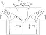
도 1은 일 실시태양인 본 발명에 의한 슬러리 분배기 사시도이다.
도 2는 도 1 슬러리 분배기의 평면도이다.
도 3은 도 1 슬러리 분배기의 정면도이다.
도 4는 도 1 슬러리 분배기의 좌측면도이다.
도 5는 프로파일 (profiling) 시스템이 제거된 도 1 슬러리 분배기의 사시도이다.
도 6은 일 실시태양인 본 발명에 의한 슬러리 분배기를 포함한 석고 슬러리 혼합 및 분배 조립체의 개략 평면도이다.
도 7은 다른 실시태양인 본 발명에 의한 슬러리 분배기를 포함한 석고 슬러리 혼합 및 분배 조립체의 개략 평면도이다.
도 8은 일 실시태양인 본 발명에 따른 석고 벽판 제조 라인 습식단 개략 입면도이다.
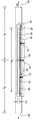
도 9는 다른 실시태양인 본 발명에 의한 슬러리 분배기의 사시도이다.
도 10은 슬러리 분배기 지지체 및 이에 수용된 도 9 슬러리 분배기의 사시도이다.
도 11은 다른 실시태양인 본 발명에 의한 슬러리 분배기의 사시도이다.
도 12는 도 11 슬러리 분배기의 다른 사시도이다.
도 13은 다른 실시태양인 본 발명에 의한 슬러리 분배기의 사시도이다.
도 14는 슬러리 분배기의 평면도이다.
도 15는 도 13 슬러리 분배기의 후면도이다.
도 16은 도 13 슬러리 분배기 바닥 부품의 평면도이다.
도 17은 도 16 바닥 부품의 사시도이다 .
도 18은 도 13 슬러리 분배기 내부 구조의 부분 사시도이다.
도 19는 도 13 슬러리 분배기 내부 구조의 또 다른 부분 사시도이다.
도 20은 다른 실시태양인 본 발명에 의한 슬러리 분배기를 포함한 석고 슬러리 혼합 및 분배 조립체의 개략 평면도이다.
도 21은 일 실시태양인 본 발명에 의한 슬러리 분배기를 포함한 석고 슬러리 혼합 및 분배 조립체에서 사용에 적합한 유체 분할기의 사시도이다.
도 22는 도 21 유체 분할기의 측단면도이다.
도 23은 일 실시태양인 압착 기구가 장착된 도 21 유체 분할기의 측면도이다.1 is a perspective view of a slurry dispenser according to an embodiment of the present invention.
Figure 2 is a top view of the slurry dispenser of Figure 1;
Figure 3 is a front view of the slurry dispenser of Figure 1;
Figure 4 is a left side view of the slurry dispenser of Figure 1;
Figure 5 is a perspective view of the Figure 1 slurry dispenser with the profiling system removed.
6 is a schematic plan view of a gypsum slurry mixing and dispensing assembly including a slurry dispenser according to one embodiment of the present invention.
7 is a schematic plan view of a gypsum slurry mixing and dispensing assembly including a slurry dispenser according to another embodiment of the present invention.
FIG. 8 is a wet-cut schematic elevation view of a gypsum wallboard manufacturing line according to an embodiment of the present invention.
9 is a perspective view of a slurry dispenser according to another embodiment of the present invention.
Figure 10 is a perspective view of the slurry dispenser support and the slurry dispenser of Figure 9 received therein.
11 is a perspective view of a slurry dispenser according to another embodiment of the present invention.
Figure 12 is another perspective view of the Figure 11 slurry dispenser.
13 is a perspective view of a slurry dispenser according to another embodiment of the present invention.
14 is a plan view of the slurry dispenser.
Figure 15 is a rear view of the slurry dispenser of Figure 13;
Figure 16 is a top view of the slurry dispenser bottom part of Figure 13;
Figure 17 is a perspective view of the bottom part of Figure 16;
Figure 18 is a partial perspective view of the internal structure of the slurry dispenser of Figure 13;
Figure 19 is another partial perspective view of the internal structure of the slurry dispenser of Figure 13;
20 is a schematic plan view of a gypsum slurry mixing and dispensing assembly including a slurry dispenser according to another embodiment of the present invention.
21 is a perspective view of a fluid divider suitable for use in a gypsum slurry mixing and dispensing assembly including a slurry dispenser according to one embodiment of the present invention.
Figure 22 is a side cross-sectional view of the fluid divider of Figure 21;
23 is a side view of the fluid divider of FIG. 21 with one embodiment of a compression mechanism mounted.
본 발명은 예를들면 석고 벽판과 같은 시멘트 제품을 포함한 제품 제조에 사용될 수 있는 다양한 실시태양들의 슬러리 분배시스템을 제공한다. 본 발명에 따른 실시양태들의 슬러리 분배기는, 예를들면 수성 기포화 석고 슬러리에서 보이는 공기상 및 액상을 포함한 것과 같은 다중-상 슬러리를 효과적으로 분포하기 위하여 제조 공정에 적용될 수 있다.The present invention provides a slurry dispensing system of various embodiments that can be used in the manufacture of products including, for example, cement products such as gypsum board. Slurry dispensers of embodiments in accordance with the present invention can be applied to manufacturing processes to effectively distribute multi-phase slurries, including, for example, air and liquid phases as seen in aqueous gaseous gypsum slurries.
본 발명에 따른 실시양태들의 분배시스템은 보드 (예를들면, 벽판) 연속 제조공정 과정에서 컨베이어 상에서 이동되는 전진 웨브 (예를들면, 페이퍼 또는 매트)에 슬러리 (예를들면, 수성 소성석고 슬러리) 를 분배하기 위하여 사용될 수 있다. 하나의 양태에서, 본 발명에 따른 슬러리 분배시스템은 수성 소성석고 슬러리를 형성하기 위하여 소성석고 및 물을 교반하는 혼합기에 부착되는 방출 도관으로써 또는 일부로써 종래 석고 건식벽 제조공정에 적용될 수 있다.A dispensing system of embodiments in accordance with the present invention may include a slurry (e.g., an aqueous fired gypsum slurry) in a forward web (e.g., paper or mat) that is moved on a conveyor in a continuous process of board (e.g., Lt; / RTI > In one embodiment, the slurry dispensing system according to the present invention can be applied to conventional gypsum dry wall manufacturing processes as part or as a discharge conduit attached to a mixer that fuses calcined gypsum and water to form an aqueous fired gypsum slurry.
본 발명에 따른 실시태양들의 슬러리 분배시스템은 (교차-기계 방향을 따라) 균일한 석고 슬러리의 광폭 분배를 달성할 목적이다. 본 발명의 슬러리 분배시스템은 종래 석고 벽판 제조에 사용된 WSR 및상대적으로 더 낮거나 더 높은 점도의 WSR을 포함한 범위의 WSR을 가지는 석고 슬러리에 적용하기에 적합하다. 또한, 본 발명의 석고 슬러리 분배시스템은 예를들면 매우 높은 기포 용적을 가지는 기포화 석고 슬러리를 포함한 수성 기포화 석고 슬러리에서 공기-액상 슬러리 상분리 조절을 조력하기 위하여 적용될 수 있다. 전진 웨브 상에 수성 소성석고 슬러리를 펼치는 것은 본원에 도시되고 설명되는 분배시스템을 이용하여 슬러리 이동 및 분배시켜 조절할 수 있다.The slurry dispensing system of embodiments according to the present invention is intended to achieve a wide distribution of uniform gypsum slurry (along the cross-machine direction). The slurry dispensing system of the present invention is suitable for application to gypsum slurries having a WSR in the range of WSR including those used in conventional gypsum board manufacture and relatively lower or higher viscosity WSR. In addition, the gypsum slurry dispensing system of the present invention can be applied to assist in controlling air-liquid slurry phase separation in aqueous gaseous gypsum slurries, including, for example, air-saturated gypsum slurries having very high bubble volumes. The spreading of the aqueous fired gypsum slurry on the forward web can be controlled by slurry movement and dispensing using the dispensing system illustrated and described herein.
본 발명에 따른 실시태양들의 석고 제품 제조방법은 본 발명에 따른 슬러리 분배기를 이용하여 전진 웨브 상에 수성 소성석고 슬러리를 분배하는 단계를 포함한다. 이동 웨브 상에 수성 소성석고 슬러리를 분배하는 방법의 다양한 실시태양들이 본원에 기재된다.The method of manufacturing gypsum products of embodiments of the present invention includes the step of dispensing an aqueous fired gypsum slurry on a forward web using a slurry dispenser in accordance with the present invention. Various embodiments of a method for dispensing an aqueous fired gypsum slurry on a moving web are described herein.
이제 도면들을 참고하면, 도 1에 본 발명에 의한 실시태양의 슬러리 분배기 (20)가 도시된다. 슬러리 분배기 (20)는 한 쌍의 공급 유입구 (24, 25)을 포함하는 공급 도관 (22), 공급 도관의 공급 유입구 (24, 25)와 유체 연통되고 분배 유출구 (30)를 포함하는 분배 도관 (28), 및 분배도관 (28)의 분배 유출구 (30) 크기 및/또는 형태를 국부적으로 가변시키는 프로파일 시스템 (32)으로 구성된다.Referring now to the drawings, there is shown in Fig. 1 a
공급 도관 (22)은 종축 또는 기계 방향 (50)에 실질적으로 수직인 횡축 또는 교차-기계 방향 (60)을 따라 실질적으로 연장된다. 제1 공급 유입구 (24)는 제2 공급 유입구 (25)와 이격된다. 제1 공급 유입구 (24) 및 제2 공급 유입구 (25)는 실질적으로 동일 면적의 개구들 (34, 35)을 형성한다. 도시된 제1 및 제2 공급 유입구 (24, 25)의 개구들 (34, 35) 모두는 본 실시예에서 원형 단면 형상을 가진다. 다른 실시양태들에서, 공급 유입구 (24, 25) 단면 형상은 적용 용도 및 공정 조건에 따라 다른 형상을 취할 수 있다. 제1 및 제2 공급 유입구 (24, 25)는 횡축 (60)에 실질적으로 수직인 개구들 (34, 35)에 의해 형성된 단면 평면에서 횡축 또는 교차-기계 방향 (60)을 따라 서로 반대측에 형성된다.The
공급 도관 (22)은 제1 및 제2 진입 구역 (36, 37) 및 중간 커넥터 구역 (39)을 포함한다. 제1 및 제2 진입 구역 (36, 37)은 대략 원통형이고 횡축 (60)을 따라 연장한다. 제1 및 제2 공급 유입구 (24, 25)는 제1 및 제2 진입 구역 (36, 37) 각각의 원위단부에 배치되고, 상호 유체 연통된다.The
커넥터 구역 (39)은 대략 원통형이고 제1 및 제2 진입 구역 (36, 37) 모두와 유체 연통된다. 커넥터 구역 (39)은 제1 및 제2 공급 유입구 (24, 25) 및 분배 도관 (28)과 유체 연통되는 공급 유출구 (40)를 형성한다. 공급 유출구 (40)는 각각 제1 및 제2 공급 유입구 (24, 25)로부터 수성 소성석고 슬러리의 제1 공급 방향 (90)의 제1 유체 및 제2 유체 방향 (91)의 제2 유체를 수용하여, 수성 소성석고 슬러리의 제1 및 제2 유체 (90, 91)를 분배 도관 (28)으로 지향한다. 공급 유출구 (40)는 제1 공급 유입구 (24) 및 제2 공급 유입구 (25) 중간에 형성된다. 도시된 공급 유출구 (40)는 도시된 실질적으로 원통형 공급 도관 (22) 만곡부에 대략 직사각형상의 개구 (42)를 형성한다.The
분배 도관 (28)은 대략 종축 (50)을 따라 연장하고 진입부 (52) 및 분배 유출구 (30)를 포함한다. 진입부 (52)는 공급 도관 (22)의 공급 유출구 (40)와, 따라서 제1 및 제2 공급 유입구 (24, 25)와도 유체 연통된다. 진입부 (52)는 공급 도관 (22)의 공급 유출구 (40)로부터 수성 소성석고 슬러리의 제1 및 제2 유체 (90, 91) 모두를 수용한다. 분배 도관 (28)의 진입부 (52)는 공급 도관 (22)의 공급 유출구 (40)와 유체 연통되는 분배 유입구 (54)를 포함한다. 도시된 분배 유입구(54)는 공급 유출구 (40)의 개구 (42)에 실질적으로 상당하는 개구 (56)를 형성한다.The
분배 유출구 (30)는 진입부 (52) 따라서 공급 유출구 (40) 및 제1 및 제2 공급 유입구 (24, 25) 모두와 유체 연통된다. 도시된 분배 유출구 (30)는 대략 직사각형상의 개구 (56)를 형성한다. 분배 유출구 (30)는 횡축 (60)을 따라 소정 길이 연장되는 폭을 가지고 종축 (50) 및 횡축 (60)과 상호 수직하는 수직축 (55)을 따라 소정 길이 연장되는 높이를 가진다. 분배 유출구 개구 (56)는 분배 유입구 (54) 개구 (56) 면적보다 작지만 (도 1-3 참고), 제1 및 제2 공급 유입구 (24, 25)의 개구들 (34, 35) 면적의 합보다는 큰 면적을 가진다 .The dispensing
슬러리 분배기는 수성 소성석고 슬러리의 조합된 제1 및 제2 유체 (90, 91)가 분배 유입구 (54)로부터 진입부 (52)를 통과하여 대략 분배 방향 (93)을 따라 분배 유출구 개구 (56)로 이동되도록 구성된다. 도시된 분배 방향 (93)은 실질적으로 종축 (50)을 따른다.The slurry dispenser is configured such that the combined first and
프로파일 시스템 (32)은 플레이트 (70), 분배 유출구 (30)에 인접하게 분배 도관 (28)에 플레이트를 고정시키는 다수의 장착 볼트 (72), 및 나사 결합되는 일련의 조정 볼트 (74, 75)를 포함한다. 장착 볼트 (72)는 분배 유출구 (30)에 인접하게 분배 도관 (28)에 플레이트 (70)를 고정시키기 위하여 사용된다. 플레이트 (70)는 분배 유출구 (30)의 폭에 걸쳐 실질적으로 횡축 (60)을 따라 연장된다. 도시된 실시양태에서, 플레이트 (70)는 긴 앵글 철 형태이다. 다른 실시양태들에서, 플레이트 (70)는 상이한 형상을 가질 수 있고 상이한 재료로 구성될 수 있다. 또 다른 실시양태들에서, 프로파일 시스템 (32)은 기타 및/또는 추가 요소들을 포함할 수 있다.The
분배 유출구 (30)가 형성된 분배 도관 (28) 일부는 탄성 유연재료로 제조되어 예를들면 조정 볼트 (74, 75)에 의해 횡측의 교차-기계 방향 (60)으로 폭을 따라 형상이 변경될 수 있다. 조정 볼트 (74, 75)는 분배 유출구 (30)의 폭에 걸쳐 횡축 (60)을 따라 상호 규칙적으로 이격된다. 조정 볼트 (74, 75)는 플레이트 (70)에 나사 체결된다. 조정 볼트 (74, 75)는 독립적으로 분배 유출구 (30) 크기 및/또는 형상을 국부적으로 변경시키도록 조정될 수 있다.A portion of the
도 2를 참조하면, 공급 도관 (22)은 실질적으로 횡축 (60)을 따라 연장된다. 제1 및 제2 공급 유입구 (24, 25)는 공급 도관 (22) 원위단부 (76, 77)에 형성된다. 공급 유출구 (40)는 실질적으로 횡축 (60)을 따라 연장되고 횡축 (60)을 따라 중앙 중간점 (78)을 포함한다. 공급 유출구 (40)는 제1 공급 유입구 (24) 및 제2 공급 유입구 (25) 사이 중간에 배치된다. 제1 및 제2 공급 유입구 (24, 25)를 통하여 실질적으로 동일 유량의 슬러리가 통과되도록, 공급 유출구 (40)는 제1 공급 유입구 (24) 및 제2 공급 유입구 (25) 사이 중간에 위치하므로 제1 공급 유입구 (24)는 공급 유출구 (40) 중앙 중간점 (78)으로부터 제1 길이 D1 에 배치되고 제2 공급 유입구 (25)는 공급 유출구 (40) 중앙 중간점 (78)로부터 제2 길이 D2에 배치되며, 제1 길이 D1 및 제2 길이 D2 는 실질적으로 같다. 다른 실시양태들에서, 제1 길이 D1 는 제2 길이 D2와 다를 수 있다.Referring to FIG. 2, the
제1 및 제2 공급 유입구 (24, 25) 및 제1 및 제2 진입 구역 (36, 37)은 종축 또는 기계 방향 (50)에 대하여 공급각 θ으로 배치된다. 도시된 실시양태에서, 공급각은 약 90°이다. 다른 실시양태들에서 제1 및 제2 공급 유입구 (24, 25)는 기계 방향 (50)에 대하여 다른 방식으로 배향될 수 있다.The first and
한 쌍의 삽입 블록 (81, 82)이 분배 도관 (28) 내부에 제공되어 한 쌍의 측벽 (84, 85)을 형성한다. 각 측벽 (84, 85)은 종축 (50)에 실질적으로 평행한 종부 (86) 및 경사부 (87)를 포함한다. 측벽 (84, 85) 종부 (86)는 분배 유출구 (30)에 인접하게 배치된다. 측벽 (84, 85) 경사부 (87)는 진입부 (52)에 인접하게 배치되고 분배 유입구 (54)에서 분배 유출구 (30) 방향으로 횡방향 내향 수렴된다 . 측벽 (84, 85) 형상은 수성 소성석고 슬러리의 조합된 유체 (90, 91)가 제1 및 제2 공급 유입구 (24, 25)로부터 측벽 (84, 85) 표면을 지나 흐르는 것을 촉진하도록 구성된다.A pair of insertion blocks 81, 82 are provided within the
일부 실시양태들에서, 삽입 블록 (81, 82)은 최소한 하나의 다른 형상을 가지는 다른 쌍들의 삽입 블록과 교체되도록 분배 도관 (28) 내부에서 탈착 가능하도록 고정되어 분배 도관 (28) 내부 형상을 변경시킬 수 있다. 다른 실시양태들에서, 측벽 (84, 85) 형상은 유체 분리를 방지하도록 변경되어 제1 및 제2 공급 유입구 (24, 25)로부터 수성 소성석고 슬러리의 조합된 유체 에지 (edge)가 측벽 (84, 85) 표면을 지나 유동된다. 다른 실시양태들에서, 측벽 (84, 85)은 기타 구조 부재들에 의해 형성된다.In some embodiments, the
사용에 있어서, 수성 소성석고 슬러리의 제1 유체는 제1 공급 방향 (90)으로 제1 공급 유입구 (24)를 통과하고, 수성 소성석고 슬러리의 제2 유체는 제2 공급 방향 (91)으로 제2 공급 유입구 (25)를 통과한다. 도시된 제1 공급 방향 (90) 및제2 공급 방향 (91)은 상호 역 방향이고 모두 횡축 (60)에 실질적으로 평행하다. 분배 도관 (28)은 커버 시트재료 웨브가 이동하는 기계 방향 (92)과 실질적으로 일치하는 종축 (50)을 따라 연장되도록 배치된다. 종축 (50)은 횡축 (60) 및 제1 및 제2 공급 방향 (90, 91)에 실질적으로 수직하다. 수성 소성석고 슬러리의 제1 및 제2 유체 (90, 91)는 슬러리 분배기 (20)에서 조합되어 수성 소성석고 슬러리의 조합된 제1 및 제2 유체 (90, 91)는 대략 종축 (50)을 따르는 분배 방향 (93) 및 기계 방향 (92)으로 분배 유출구 (30)를 통과한다.In use, the first fluid of the aqueous fired gypsum slurry passes through the
프로파일 시스템 (32)은 분배 유출구 (30) 크기 및/또는 형상을 국부적으로 변경시키도록 구성되어 슬러리 분배기 (20)로부터 분배되는 수성 소성석고 슬러리의 조합된 제1 및 제2 유체 (90, 91)의 유동 패턴을 변경시킨다. 예를들면, 중간-선 조정 볼트 (75)를 아래로 조여 분배 유출구 (30)의 횡방향 중앙 중간점 (94)을 누르면 종축 (50)에서 먼 양 교차-기계 방향 (60)에서 에지 유동각이 커져서 확산이 용이하고 교차-기계 방향 (60)에서 슬러리 유동 균일성이 개선된다.The
도 3을 참조하면, 분배 유출구 (30) 개구 (56)는 대략 직사각형이다. 도시된 분배 유출구 (30)는 24인치의 폭 W1 및 1인치의 높이 H1 을 가진다. 본 직사각형 면적은 명목상 공정 운전 속도 분당 350 피트 (fpm)로 이동 커버시트를 전진시키는 제조 라인에 사용하도록 설정된 것이다. 다른 실시양태들에서, 상이한 크기 및/또는 형상을 가지는 분배 유출구가 명목상 운전속도 350 fpm의 제조 라인에 적용될 수 있다. 또 다른 실시양태들에서, 분배 유출구 개구의 크기 및/또는 형상은 특정 운전 특성에 따라 소정 라인에서 원하는 결과를 얻도록 또는 상이한 운전 속도 및 운전 변수의 제조 라인에 사용하도록 변경될 수 있다.Referring to FIG. 3, the
분배 유출구 (30)는 실질적으로 횡축 (60)을 따라 연장된다. 분배 유출구 (30)는 횡축 (60)을 따라 분배 유입구 (54)보다 좁다. 분배 유출구 (30)는 제1 공급 유입구 (24) 및 제2 공급 유입구 (25) 사이 중간에 위치하고 제1 공급 유입구 (24) 및 제2 공급 유입구 (25)는 분배 유출구 (30)의 횡측 중앙 중간점 (94)으로부터 실질적으로 동일한 길이 D1, D2에서 배치된다. 분배 유출구 (30)는 탄성 유연재료로 제조되어 형상 및/또는 크기는 횡축 (60)을 따라, 예를들면 조정 볼트 (74, 75)에 의해 변경될 수 있다.The dispensing
프로파일 시스템 (32)은 횡축 (60)을 따라 분배 유출구 (30) 형상 및/또는 크기를 변경시키고 분배 유출구 (30)를 새로운 형상으로 유지시킨다. 플레이트 (70)는 분배 유출구 (30)를 새로운 형상으로 변경할 때 조정 볼트 (74, 75)에 의한 조정 결과 조정 볼트 (74, 75) 에 의해 인가되는 대향력에 견디기에 적합한 강도의 재료로 제조된다. 프로파일 시스템 (32)은 (예를들면, 상이한 슬러리 밀도 및/또는 상이한 공급 유입구 속도로 인하여) 분배 유출구 (30)로부터 배출되는 슬러리 유체 프로파일 변동을 해소하여 분배 도관 (28)에서 나오는 슬러리 출구 패턴은 더욱 균일하도록 조력하기 위하여 사용될 수 있다.The
다른 실시양태들에서, 조정 볼트 개수는 가변적이어서 인접 조정 볼트 사이 간격은 변할 수 있다. 분배 유출구 (30)의 폭이 상이한 다른 실시양태들에서, 조정 볼트 개수가 가변되어 원하는 인접 볼트 간격을 달성할 수 있다. 또 다른 실시양태들에서,인접 볼트 사이 간격들은 횡축 (60)을 따라 변경될 수 있어, 예를들면 분배 유출구 (30)의 측 에지 (97, 98)에 더욱 국부적인-가변 제어를 제공할 수 있다.In other embodiments, the number of adjustment bolts is variable, so that the spacing between adjacent adjustment bolts can vary. In other embodiments in which the width of the dispensing
도 4를 참조하면, 분배 도관 (28)은 진입부 (52)와 유체 연통되는 수렴부 (102)를 포함한다. 수렴부 (102)는 수렴부 (102)를 통과하는 수성 소성석고 슬러리 유체에 인가되는 국부 전단을 인접 영역에 인가되는 국부 전단보다 효과적으로 높이기 위하여 인접 영역 높이보다 더 낮은 높이를 가진다. 수렴부 (102)는 바닥면 (104) 및 최상면 (105)을 포함한다. 최상면 (105)은 바닥면 (104)과 이격되고 경사를 이루고 최상면 (105)은 진입부 (52)에 인접한 최상면 (105) 제1 에지 (107)에서 바닥면 (104)으로부터 제1 높이 H2 및 분배 유출구 (30)에 인접한 최상면 (105) 제2 에지 (108)에서 바닥면 (104)으로부터 제2 높이 H3 로 형성된다. 제1 높이 H2 는 제2 높이 H3 보다 높다 (도 5 함께 참고).Referring to FIG. 4, the
수렴부 (102) 및 분배 유출구 (30) 높이 H1 는 연동되어 유동 안정성을 개선하기 위하여 분배 도관 (28)에서 분배되는 수성 소성석고의 조합된 유체의 평균속도를 가속시킨다. 분배 유출구 (30)의 높이 및/또는 폭은 분배 슬러리 평균속도를 조정하기 위하여 가변될 수 있다.The height H1 of the converging
도시된 공급 도관 (22)은 중공의, 대략 원통관이다. 도시된 공급 유입구의 개구들 (34, 35)은 명목상 라인 속도 350 fpm에 사용되는 약 3인치 직경 Ø1 을 가진다. 다른 실시양태들에서, 공급 유입구의 개구들 (34, 35) 크기는 변경될 수 있다. 일반적으로, 공급 유입구 개구들 (34, 35) 크기는 명목상 라인 속도의 함수로 가변된다.The illustrated
도 5를 참조하면, 프로파일 시스템이 제거된 슬러리 분배기 (20)가 도시된다. 다른 실시양태들에서, 공급 도관 (22)은 다른 형상을 가질 수 있고 공급 유입구 (24, 25)는 상이한 단면 형상을 가질 수 있다. 또 다른 실시양태들에서, 공급 도관 (22)은 횡축 (60)으로 길이에 따라 변경되는 단면 형상을 가질 수 있다. 유사하게, 다른 실시양태들에서, 분배 도관 (28) 및/또는 분배 유출구 (30)는 상이한 형상들을 가질 수 있다.Referring to FIG. 5, a
공급 도관 (22) 및 분배 도관 (28)은 임의의 적합한 재료로 구성될 수 있다. 일부 실시양태들에서, 공급 도관 (22) 및 분배 도관 (28)은 임의의 적합한 실질적으로 강성 재료로 구성될 수 있다. 예를들면, 적절하게 강성인 플라스틱 또는 금속이 공급 도관 (22)에 적용될 수 있고, 적합한 탄성 유연재료가 공급 도관 (22)에 사용될 수 있다.The
분배 유출구의 개구 폭 및/또는 높이는 상이한 운전 조건들에 대한 상이한 실시양태들에서 가변된다는 것을 고려할 수 있다. 일반적으로, 본원에 개시된 다양한 실시태양들의 슬러리 분배기 전체 치수는 제조품 유형, 예를들면, 제조품 두께 및/또는 폭, 제조 라인 속도, 분배기를 통한 슬러리 적치 속도, 슬러리 점도, 및 기타 등에 따라 커지거나 작아질 수 있다. 예를들면, 종래에는 명목상 54 인치 이하였던 벽판 제조공정에 사용된 분배 유출구의 횡축 폭은, 일부 실시양태들에서 약 8 내지 약 54인치, 다른 실시양태들에서 약 18 인치 내지 약 30 인치일 수 있다. 일부 실시양태들에서 분배 유출구 높이는 약 3/16 인치 내지 약 2인치일 수 있고, 다른 실시양태들에서 약 3/16 인치 내지 1 인치일 수 있다. 직사각형 분배 유출구를 포함하는 일부 실시양태들에서, 유출구 개구인 직사각형 높이에 대한 직사각형 폭 비율은 약 4 이상, 다른 실시양태들에서 약 8 이상, 일부 실시양태들에서 약 4 내지 약 288, 다른 실시양태들에서 약 9 내지 약 288, 다른 실시양태들에서 약 18 내지 약 288, 및 또 다른 실시양태들에서 약 18 내지 약 160이다.It is contemplated that the opening width and / or height of the dispensing outlet may vary in different embodiments for different operating conditions. In general, the overall dimensions of the slurry dispenser of the various embodiments disclosed herein may be larger or smaller depending on the type of article of manufacture, e.g., article thickness and / or width, manufacturing line speed, slurry speed through a dispenser, slurry viscosity, Can be. For example, the transverse width of the dispensing outlet used in wallboard manufacturing processes, which was conventionally less than 54 inches nominal, may be from about 8 to about 54 inches in some embodiments, from about 18 inches to about 30 inches in other embodiments have. In some embodiments, the dispense outlet height may be about 3/16 inches to about 2 inches, and in other embodiments, about 3/16 inches to about 1 inch. In some embodiments including a rectangular distribution outlet, the rectangular width ratio to the rectangular height of the outlet opening is at least about 4, at least about 8 at other embodiments, from about 4 to about 288 in some embodiments, From about 9 to about 288 in other embodiments, from about 18 to about 288 in other embodiments, and from about 18 to about 160 in yet other embodiments.
본 발명에 따른 슬러리 분배기는 임의의 적합한 재료로 구성될 수 있다. 일부 실시양태들에서, 슬러리 분배기는 유출구가 예를들면 프로파일 시스템에 의해 변경될 수 있는 적합한 재료를 포함한 임의의 적합한 실질적인 강성 재료로 구성될 수 있다. 예를들면, 적절하게 강성인 플라스틱, 예를들면 초고분자량 (UHMW) 플라스틱 또는 금속이 적용될 수 있다. 다른 실시양태들에서, 본 발명에 따른 슬러리 분배기는 예를들면 폴리염화비닐 (PVC) 또는 우레탄을 포함한 예를들면 적합한 유연 플라스틱 재료와 같은 유연 재료로 제조될 수 있다.The slurry dispenser according to the present invention may be constructed of any suitable material. In some embodiments, the slurry dispenser may be constructed of any suitable substantially rigid material, including any suitable material from which the outlet can be altered, for example, by a profile system. For example, appropriately rigid plastics such as ultrahigh molecular weight (UHMW) plastics or metals can be applied. In other embodiments, the slurry dispenser according to the present invention may be made of a flexible material, such as, for example, a suitable flexible plastic material, for example comprising polyvinyl chloride (PVC) or urethane.
임의의 적합한 기술이 본 발명에 따른 슬러리 분배기 제작에 적용될 수 있다. 예를들면, 슬러리 분배기가 유연 재료, 예를들면 PVC 또는 우레탄으로 제조되는 실시태양들에서, 다중-부품 몰드가 사용될 수 있다. 다중-부품 몰드 외면은 슬러리 분배기의 내부 유동 구조를 형성한다. 다중-부품 몰드는 임의의 적합한 재료, 예를들면 알루미늄으로 제조될 수 있다. 유연 재료, 예를들면PVC 또는 우레탄의 가열용액에 몰드를 담근다. 몰드를 담지 재료에서 꺼낸다.Any suitable technique may be applied to the slurry dispenser fabrication according to the present invention. For example, in embodiments where the slurry dispenser is made of a flexible material, such as PVC or urethane, a multi-part mold may be used. The outer surface of the multi-part mold forms the internal flow structure of the slurry dispenser. The multi-part mold may be made of any suitable material, for example, aluminum. Immerse the mold in a heating solution of a flexible material, for example PVC or urethane. The mold is taken out of the support material.
서로 결합되어 소망 구조를 제공하는 다중 개별 알루미늄 부품들로 몰드를 제작함으로써, 몰드 부품들은 서로 해체되고 여전히 가온인 용액에서 꺼낼 수 있다. 충분한 고온에서, 유연 재료는 성형 슬러리 분배기 작은 면적을 통하여 할렬없이 더 큰 몰드 부품을 꺼낼 수 있을 정도로 유연한다. 일부 실시양태들에서, 몰드 부품 면적은 몰드 부품이 꺼내지는성형 슬러리 분배기 면적의 약 115% 이내, 및 다른 실시양태들에서 약 110%이내이다. 연결 볼트들이 몰드 부품들을 상호 체결하거나 정렬시켜 결합부에서 플래싱 (flashing)을 줄이고 볼트는 제거되어 성형 슬러리 분배기 내부에서 몰드를 꺼낼 때 다중-부품 몰드를 해체시킨다.By fabricating the mold with multiple individual aluminum parts that are joined together to provide the desired structure, the mold parts can be disassociated from each other and still be removed from the warmed solution. At sufficient high temperatures, the flexible material is flexible enough to take out larger mold parts without splitting through a small area of the shaped slurry dispenser. In some embodiments, the mold part area is within about 115% of the area of the formed slurry dispenser from which the mold part is taken, and within about 110% in other embodiments. The connecting bolts fasten or align the mold parts to each other to reduce flashing at the joint and the bolts removed to disassemble the multi-part mold when the mold is taken out of the molded slurry dispenser.
본 발명의 다른 태양에 의하면, 석고 슬러리 혼합 및 분배 조립체는 본 발명에 따른 슬러리 분배기를 포함한다. 슬러리 분배기는 수성 소성석고 슬러리를 형성하기 위하여 물 및 소성석고를 교반하는 석고 슬러리 혼합기와 유체 연통되도록 배치된다. 일 실시태양에서, 슬러리 분배기는 석고 슬러리 혼합기로부터 수성 소성석고 슬러리의 제1 유체 및 제2 유체를 수용하고 수성 소성석고 슬러리의 제1 유체 및 제2 유체를 전진 웨브 상에 분배한다.According to another aspect of the invention, the gypsum slurry mixing and dispensing assembly comprises a slurry dispenser according to the present invention. The slurry dispenser is disposed in fluid communication with a gypsum slurry mixer that agitates water and fired gypsum to form an aqueous fired gypsum slurry. In one embodiment, the slurry dispenser receives the first fluid and the second fluid of the aqueous fired gypsum slurry from the gypsum slurry mixer and dispenses the first fluid and the second fluid of the aqueous fired gypsum slurry onto the forward web.
본 발명에 따라 구현된 석고 슬러리 분배기는 수성 소성석고 슬러리의 광폭 기계 방향 분배를 제공하여 고점성 /저 WSR 석고 슬러리를 성형대 위로 이동하는 커버 시트재료 웨브에 용이하게 분산시킨다. 또한 석고 슬러리 분배시스템은 공기-액상 슬러리 상분리를 방지한다.The gypsum slurry dispenser implemented in accordance with the present invention provides a wide mechanical directional distribution of the aqueous fired gypsum slurry to facilitate dispersing the high viscosity / low WSR gypsum slurry in the cover sheet material web moving on the molding table. The gypsum slurry distribution system also prevents air-liquid slurry phase separation.
슬러리 분배기는 당업계에서 알려진 종래 석고 슬러리 혼합기 (예를들면, 핀 혼합기)의 방출 도관 또는 일부로서 구성될 수 있다. 슬러리 분배기는 종래 방출 도관 요소들과 함께 사용될 수 있다. 예를들면, 슬러리 분배기는 당업계에서 알려진 게이트-캐니스터-부트 (gate-canister-boot) 배열 또는 미국특허번호 6,494,609; 6,874,930; 7,007,914; 및/또는 7,296,919에 기재된 방출 도관 배열의 요소들과 함께 사용될 수 있다.The slurry dispenser may be configured as a discharge conduit or part of a conventional gypsum slurry mixer (e.g., a pin mixer) known in the art. The slurry dispenser can be used with conventional discharge conduit elements. For example, the slurry dispenser may be a gate-canister-boot arrangement as known in the art or as disclosed in U.S. Patent Nos. 6,494,609; 6,874,930; 7,007,914; And / or 7,296,919.
본 발명에 따른 슬러리 분배기는 바람직하게는 기존 벽판 제조시스템에서 개장 (retrofit)으로 구성된다. 슬러리 분배기는 바람직하게는 종래 방출 도관에서 사용되는 종래 단일 또는 다중-분기 부트를 교체하기 위하여 적용될 수 있다. 본 석고 슬러리 분배기는 미국특허번호 6,874,930 또는 7,007,914에 도시된 바와 같은 기존 슬러리 방출 도관 배열에 대한, 예를들면, 원위 분배 분출기 또는 부트 대체품으로 개장될 수 있다. 그러나, 일부 실시양태들에서, 슬러리 분배기는, 달리, 하나 이상의 부트 유출구(들)에 부착될 수 있다.The slurry dispenser according to the present invention is preferably configured retrofit in a conventional wallboard manufacturing system. The slurry dispenser is preferably adapted to replace conventional single or multi-branch boots used in conventional discharge conduits. The gypsum slurry dispenser may be retrofitted with a conventional dispenser or boot substitute for an existing slurry discharge conduit arrangement, for example as shown in U.S. Patent No. 6,874,930 or 7,007,914. However, in some embodiments, the slurry dispenser may otherwise be attached to one or more of the boot outlet (s).
도 6을 참조하면, 일 실시태양인 석고 슬러리 혼합 및 분배 조립체 (110)는 슬러리 분배기 (120)와 유체 연통되는 석고 슬러리 혼합기 (112)를 포함한다. 석고 슬러리 혼합기 (112)는 수성 소성석고 슬러리를 형성하기 위하여 물 및 소성석고를 교반하도록 구성된다. 물 및 소성석고 모두는 당업계에 알려진 하나 이상의 유입구를 통하여 혼합기 (112)에 공급된다. 임의의 적합한 혼합기가 슬러리 분배기와 함께 사용될 수 있다.Referring to FIG. 6, an embodiment of a gypsum slurry mixing and dispensing
슬러리 분배기 (120)는 석고 슬러리 혼합기 (112)와 유체 연통된다. 슬러리 분배기 (120)는 석고 슬러리 혼합기 (112)로부터 수성 소성석고 슬러리의 제1 유체를 수용하는 제1 공급 유입구 (124), 석고 슬러리 혼합기 (112)로부터 수성 소성석고 슬러리의 제2 유체를 수용하는 제2 공급 유입구 (125), 및 제1 및 제2 공급 유입구 (124, 125) 모두와 유체 연통되고 슬러리 분배기 (120)로부터 수성 소성석고 슬러리의 제1 유체 및 제2 유체를 배출하는 분배 유출구 (130)를 포함한다.The
슬러리 분배기 (120)는 분배 도관 (128)과 유체 연통되는 공급 도관 (122)을 포함한다. 공급 도관은 대략 횡축 (60)을 따라 연장되며 제1 공급 유입구 (124), 제1 공급 유입구 (124)와 이격되는 제2 공급 유입구 (125), 및 제1 공급 유입구 (124) 및 제2 공급 유입구 (125)와 유체 연통되는 공급 유출구 (140)를 포함한다. 분배 도관 (128)은 종축 (60) 과 실질적으로 수직인 대략 종축 (50)을 따라 연장되며, 진입부 (152) 및 분배 유출구 (130)를 포함한다. 진입부 (152)는 공급 도관 (122)의 공급 유출구 (140)와 유체 연통되어 진입부 (152)는 공급 도관 (122)의 공급 유출구 (140)로부터 수성 소성석고 슬러리의 제1 및 제2 유체 모두를 수용한다. 분배 유출구 (130)는 진입부 (152)와 유체 연통된다. 분배 도관 (128)의 분배 유출구 (130)는 횡축 (60)을 따라 소정 길이 연장된다. 슬러리 분배기 (120)는 도 1의 슬러리 분배기의 기타 측면들에서 유사할 수 있다.The
이송 도관 (114)은 석고 슬러리 혼합기 (112) 및 슬러리 분배기 (120) 사이에서 이들과 유체 연통된다. 이송 도관 (114)은 주 이송통로 (115), 슬러리 분배기 (120)의 제1 공급 유입구 (124)와 유체 연통되는 제1 이송 분기 (117), 및 슬러리 분배기 (120)의 제2 공급 유입구 (125)와 유체 연통되는 제2 이송 분기 (118)를 포함한다. 주 이송 통로 (115)는 제1 및 제2 이송 분기 (117, 118) 모두와 유체 연통된다. 다른 실시양태들에서, 제1 및 제2 이송 분기 (117, 118)는 독립적으로 석고 슬러리 혼합기 (112)와 유체 연통된다.The
이송 도관 (114)은 임의의 적합한 재료로 제조되고 상이한 형상들을 가질 수 있다. 일부 실시양태들에서, 이송 도관은 유연성 도관으로 구성될 수 있다.The
수성 기포 공급 도관 (121)은 최소한 하나의 석고 슬러리 혼합기 (112) 및 이송 도관 (114)과 유체 연통된다. 공급원으로부터 수성 기포는 혼합기 (112) 하류 임의의 적합한 지점 및/또는 혼합기 (112) 자체에 있는 기포 공급 도관 (121)를 통하여 구성 재료들에 첨가되어 기포화 석고 슬러리를 형성하고 이것은 슬러리 분배기 (120)로 제공된다. 도시된 실시양태에서, 기포 공급 도관 (121)은 석고 슬러리 혼합기 (112) 하류에 배치된다. 도시된 실시양태에서, 수성 기포 공급 도관 (121)은 매니폴드 유형의 배열을 가지고 예를들면, 미국특허번호 6,874,930에 기재된 바와 같이 이송 도관 (114)에 연결된 분사링 또는 블록에 기포를 공급한다.The aqueous
다른 실시양태들에서, 하나 이상의 제2 기포 공급 도관들이 혼합기와 유체 연통되도록 제공될 수 있다. 또 다른 실시양태들에서, 수성 기포 공급 도관(들)은 석고 슬러리 혼합기만과 유체 연통될 수 있다. 당업자가 이해하듯이, 조립체 내 상대 위치를 포함하여 수성 기포를 석고 슬러리 혼합 및 분배 조립체 (110) 내 석고 슬러리로 도입하는 수단은, 용도에 적합한 보드를 제조하기 위하여 석고 슬러리에 균일한 수성 기포 분산을 제공하도록 가변 및/또는 최적화될 수 있다.In other embodiments, the one or more second bubble supply conduits may be provided to be in fluid communication with the mixer. In yet other embodiments, the aqueous bubble supply conduit (s) may be in fluid communication with only the gypsum slurry mixer. As will be understood by those skilled in the art, the means for introducing the aqueous bubbles into the gypsum slurry in the gypsum slurry mixing and dispensing
기포화 석고 슬러리가 응결되고 건조될 때, 슬러리에 분산된 기포는 기공을 형성하여 벽판 전체 밀도를 낮춘다. 형성된 벽판 제품이 소망 중량 범위에 있도록 기포 및/또는 기포 내 공기 함량이 가변되어 보드 건조 밀도를 조정한다.When the gypsum slurry is coagulated and dried, the bubbles dispersed in the slurry form pores to lower the overall density of the wallboard. The air content in the bubbles and / or bubbles is varied to adjust the board dry density so that the formed wallboard product is within the desired weight range.
임의의 적합한 기포제가 사용될 수 있다. 바람직하게는, 기포제 및 물의 혼합물 스트림이 기포발생기로 향하고, 형성된 수성 기포 스트림이 발생기를 떠나 소성석고 슬러리와 혼합되는 연속 방식으로 수성 기포가 생성된다. 예시적인 적합한 기포제들은, 예를들면 미국특허번호 5,683,635 및 5,643,510에 기재된다.Any suitable foaming agent may be used. Preferably, aqueous bubbles are produced in a continuous manner in which a mixture stream of bubbling agent and water is directed to the bubbler and the formed aqueous bubbling stream leaves the generator and is mixed with the fired gypsum slurry. Exemplary suitable foaming agents are described, for example, in U.S. Pat. Nos. 5,683,635 and 5,643,510.
하나 이상의 유량-변경 요소 (123)가 이송 도관 (114)과 연결되어 석고 슬러리 혼합기 (112)로부터의 수성 소성석고 슬러리 제1 및 제2 유체를 제어할 수 있다. 유량-변경 요소(들) (123)은 수성 소성석고 슬러리의 제1 유체 및 제2 유체의 운전 특성을 제어하기 위하여 사용된다. 도 6에서 도시된 실시양태에서, 유량-변경 요소(들) (123)은 주 이송 통로 (115)와 연결된다. 적합한 유량-변경 요소들의 예시로는 예를들면 미국특허번호 6,494,609; 6,874,930; 7,007,914; 및 7,296,919에 기재된 것들을 포함한 유량제한기, 감압기, 수축밸브, 캐니스터 기타 등을 포함한다.One or more flow-modifying
도 7을 참조하면, 다른 실시양태의 석고 슬러리 혼합 및 분배 조립체 (210)가 도시된다. 석고 슬러리 혼합 및 분배 조립체 (210)는 슬러리 분배기 (220)와 유체 연통되는 석고 슬러리 혼합기 (212)를 포함한다. 석고 슬러리 혼합기 (212)는 수성 소성석고 슬러리를 형성하기 위하여 물 및 소성석고를 교반하도록 구성된다. 슬러리 분배기 (220)는 도 1의 슬러리 분배기 (120) 구성과 유사할 수 있다.Referring to Figure 7, another embodiment of the gypsum slurry mixing and dispensing
이송 도관 (214)은 석고 슬러리 혼합기 (212) 및 슬러리 분배기 (220) 사이에서 유체 연통된다. 이송 도관 (214)은 주 이송 통로 (215), 슬러리 분배기 (220)의 제1 공급 유입구 (224)와 유체 연통되는 제1 이송 분기 (217), 및 슬러리 분배기 (220)의 제2 공급 유입구 (225)와 유체 연통되는 제2 이송 분기 (218)를 포함한다.The
주 이송 통로 (215)는 석고 슬러리 혼합기 (212) 및 제1 및 제2 이송 분기 (217, 218) 모두 사이에서 유체 연통된다. 수성 기포 공급 도관 (221)은 최소한 하나의 석고 슬러리 혼합기 (212) 및 이송 도관 (214)과 유체 연통된다. 도시된 실시양태에서, 수성 기포 공급 도관 (221)은 이송 도관 (214)의 주 이송 통로 (215)와 연결된다.The
제1 이송 분기 (217)는 석고 슬러리 혼합기 (212) 및 슬러리 분배기 (220) 제1 공급 유입구 (224) 사이에서 유체 연통된다. 최소한 하나의 제1 유량-변경 요소 (223)는 제1 이송 분기 (217)와 연결되어 석고 슬러리 혼합기 (212)로부터의 수성 소성석고 슬러리의 제1 유체를 제어한다.The
제2 이송 분기 (218)는 석고 슬러리 혼합기 (212) 및 슬러리 분배기 (220) 제2 공급 유입구 (225) 사이에 유체 연통된다. 최소한 하나의 제2 유량-변경 요소 (227)는 제2 이송 분기 (218)에 연결되고 석고 슬러리 혼합기 (212)로부터 수성 소성석고 슬러리의 제2 유체를 제어한다.The
제1 및 제2 유량-변경 요소 (223, 227)는 수성 소성석고 슬러리의 제1 유체 및 제2 유체 운전 특성을 조절하도록 작동한다. 제1 및 제2 유량-변경 요소 (223, 227)는 독립적으로 작동될 수 있다. 일부 실시양태들에서, 제1 및 제2 유량-변경 요소 (223, 227)는 슬러리의 제1 및 제2 유체를 상대적으로 느리고 상대적으로 빠른 평균속도 사이에서 역방식으로 교대로 전달하도록 구동되어 소정 시간에 제1 슬러리는 슬러리의 제2 유체보다 빠른 평균속도로 전달되고 다른 시점에서 제1 슬러리는 슬러리의 제2 유체보다 느린 평균속도로 전달될 수 있다.The first and second flow-modifying
당업자가 이해하듯, 하나 또는 양 커버 시트재료 웨브는 웨브 상에 당업계에서 스킴 코트라고 칭하는 (코어 구성 석고슬러리에 비하여) 상대적으로 농후한 극히 박막의 석고슬러리, 및/또는 필요한 경우 웨브 에지에 최소한 하나의 더욱 농후한 석고 슬러리 스트림으로 예비-처리된다. 이러한 목적을 위하여, 혼합기 (212)는 슬러리 분배기에 이송되는 수성 소성석고 슬러리의 제1 유체 및 제2 유체보다 상대적으로 더욱 농후한 수성 소성석고 농후 슬러리 스트림 (즉, “전면 스킴 코트/경성 (hard) 에지 스트림”) 침적을 위한 제1 보조 도관 (229)을 포함한다. 제1 보조 도관 (229)은 스킴 코트층을 이동 커버시트 웨브에 인가하고 당업계에 알려진 바와 같이 이동 웨브 폭보다 좁은 롤러 (231) 폭에 의해 이동 웨브 가장자리에 경성 에지를 형성하는스킴 코트 롤러 (231) 상류에서 전면 스킴 코트/경성 에지 스트림을 이동 커버시트 웨브 상에 침적시킨다. 경성 에지는 웨브에 농후층을 인가하는 롤러 단부 주위로 농후 슬러리 일부를 지향시켜 농후층을 형성하는 것과 동일한 농후 슬러리로 형성될 수 있다.As one of ordinary skill in the art will appreciate, one or both cover sheet material webs can be provided on the web with an extremely thin gypsum slurry, which is relatively dense (compared to a core gypsum slurry) referred to in the art as a scheme coat, and / Pre-treated with one more thick gypsum slurry stream. For this purpose, the
또한 혼합기 (212)는 슬러리 분배기에 이송되는 수성 소성석고 슬러리의 제1 유체 및 제2 유체보다 상대적으로 더욱 농후한 농후 수성 소성석고 슬러리 스트림 (즉, “배면 스킴 코트 스트림”)을 침적하는 제2 보조 도관 (233)을 포함한다. 제2 보조 도관 (233)은 당업계에 알려진 바와 같이스킴 코트층을 제2 이동 커버시트 웨브에 인가하는 스킴 코트 롤러 (237)의 (제2 웨브 이동방향) 상류의 제2 이동 커버시트 웨브 상에 배면 스킴 코트 스트림을 침적한다 (도 8 역시 참조).The
다른 실시양태들에서, 별개의 보조 도관들이 혼합기에 연결되어 하나 이상의 별개의 에지 스트림을 이동 커버시트 웨브에 이송할 수 있다. 기타 적합한 장비 (예를들면 보조 혼합기)가 보조 도관에 제공되어 슬러리의 기포를 기계적으로 파괴 및/또는 적합한 소포제를 이용하여 기포를 화학적으로 파괴하여 슬러리를 더욱 농후하게 제조할 수 있다.In other embodiments, separate auxiliary conduits may be connected to the mixer to deliver one or more separate edge streams to the moving cover sheet web. Other suitable equipment (such as an auxiliary mixer) may be provided in the auxiliary conduit to mechanically break the bubbles of the slurry and / or chemically break the bubbles using a suitable defoaming agent to make the slurry more dense.
또 다른 실시양태들에서, 제1 및 제2 이송 분기는 각각 기포 공급 도관을 가지고 각각 독립적으로 수성 기포를 슬러리 분배기로 이송되는 수성 소성석고 슬러리의 제1 유체 및 제2 유체에 도입할 수 있다. 또 다른 실시양태들에서, 다수의 혼합기가 제공되어 독립적인 슬러리 스트림을 본 발명에 따른 슬러리 분배기의 제1 및 제2 공급 유입구로 공급할 수 있다. 기타 실시태양들도 가능하다는 것을 이해하여야 한다.In still other embodiments, the first and second transfer branches may each introduce bubbles of water, independently of each other, into the first and second fluids of the aqueous fired gypsum slurry transferred to the slurry dispenser. In still other embodiments, multiple mixers are provided to supply an independent slurry stream to the first and second feed inlets of the slurry dispenser according to the present invention. It is to be understood that other embodiments are possible.
도 8을 참조하면, 석고 벽판 제조 라인의 예시적 습식단 (311)이 도시된다. 습식단 (311)은 슬러리 분배기 (320), 슬러리 분배기 (320) 상류에 배치되고 제1 이동 커버시트재료 웨브 (339)가 사이에 개재되도록 성형대 (338) 상부에 지지되는 경성 에지/전면 스킴 코트 롤러 (331), 제2 이동 커버시트재료 웨브 (343)가 사이에 개재되도록 지지요소 (341) 상부에 배치되는 배면 스킴 코트 롤러 (337), 및 예비형체를 소망 두께로 형상화하는 성형 스테이션 (345)을 포함하는 석고 슬러리 혼합 및 분배 조립체 (310)로 구성된다. 스킴 코트 롤러 (331, 337), 성형대 (338), 지지요소 (341), 및 성형 스테이션 (345)은 당업계에 알려진 바와 같이 목적에 적합한 종래 장비로 구성될 수 있다. 습식단 (311)에는 당업계에 공지된 기타 종래 장비가 구비될 수 있다.Referring to Fig. 8, an exemplary
본 발명의 다른 양태에서, 본 발명에 따른 슬러리 분배기는 다양한 제조공정에 적용될 수 있다. 예를들면, 일 실시태양에서, 슬러리 분배시스템은 석고 제품 제조방법에 사용될 수 있다. 슬러리 분배기는 제1 전진 웨브 (339) 상에 수성 소성석고 슬러리를 분배하기 위하여 적용될 수 있다.In another aspect of the present invention, the slurry dispenser according to the present invention can be applied to various manufacturing processes. For example, in one embodiment, a slurry dispensing system can be used in a gypsum product manufacturing method. The slurry dispenser may be applied to dispense the aqueous fired gypsum slurry on the first advancing
물과 소성석고는 혼합기 (312)에서 혼합되어 수성 소성석고 슬러리의 제1 및 제2 유체 (347, 348)를 형성한다. 일부 실시양태들에서, 물과 소성석고는 물-대-소성석고 비율이 약 0.5 내지 약 1.3, 및 기타 실시태양들에서 약 0.75 이하로 연속하여 혼합기에 투입될 수 있다.The water and calcined gypsum are mixed in a
석고 보드 제품은 전형적으로 전진 웨브 (339)가 마감 보드의 “전면” 커버시트로 기능하도록 “전면 하향”으로 형성된다. 전면 스킴 코트/경성 에지 스트림 (349) (최소한 하나의 수성 소성석고 슬러리의 제1 유체 및 제2 유체 대비 더욱 농후한 수성 소성석고 슬러리 층)은 기계 방향 (392) 기준으로 경성 에지/전면 스킴 코트 롤러 (331) 상류의 제1 이동 웨브 (339)에 인가되어 스킴 코트층을 제1 웨브 (339)에 부어 보드의 경성 에지를 형성한다.The gypsum board product is typically formed " front-down " such that the
수성 소성석고 슬러리의 제1 유체 (347) 및 제2 유체 (348) 각각은 슬러리 분배기 (320)의 제1 공급 유입구 (324) 및 제2 공급 유입구 (325)를 통과한다. 제1 공급 유입구 (324) 및 제2 공급 유입구 (325) 각각은 슬러리 분배기 (320) 반대 측에 위치한다. 수성 소성석고 슬러리의 제1 및 제2 유체 (347, 348)는 슬러리 분배기 (320)에서 조합된다. 수성 소성석고 슬러리의 제1 및 제2 유체 (347, 348)는 실질적으로 공기-액상 슬러리 상분리가 거의 또는 전혀 일어나지 않고 실질적으로 와류가 아닌 층류 방식으로슬러리 분배기 (320) 유로를 따라 이동한다.Each of the
제1 이동 웨브 (339)는 종축 (50)을 따라 이동한다. 수성 소성석고 슬러리의 제1 유체 (347)는 제1 공급 방향 (90)으로 제1 공급 유입구 (324)를 통과하고, 수성 소성석고 슬러리의 제2 유체 (348)는 제1 공급 방향 (90)과 대향 방향인 제2 공급 방향 (91)으로 제2 공급 유입구 (325)를 통과한다. 제1 및 제2 공급 방향 (90, 91)은 실질적으로 종축 (50)과 실질적으로 수직인 횡축 (60)과 평행하다 (도 2 역시 참조).The
분배 도관 (328)은 제1 커버시트 재료 웨브 (339)가 이동하는 기계 방향 (392)과 실질적으로 일치하는 종축 (50)을 따라 연장되도록 배치된다. 바람직하게는, (횡축 / 교차-기계 방향을 따라 취한) 분배 유출구 (330) 중앙 중간점은 실질적으로 제1 이동 커버시트 (339)의 중앙 중간점과 일치한다. 수성 소성석고 슬러리의 제1 및 제2 유체 (347, 348)는 슬러리 분배기 (320)에서 조합되어 수성 소성석고 슬러리의 조합된 제1 및 제2 유체 (351)는 대략 종축 (50)을 따르는 분배 방향 (93)으로 분배 유출구 (330)를 통과한다.The
일부 실시양태들에서, 분배 도관 (328)은 성형대를 따라 이동하는 제1 웨브 (339)의 종축 (50) 및 횡축 (60)에 의해 정의되는 평면과 실질적으로 평행하게 위치한다. 다른 실시양태들에서, 분배 도관의 진입부는 제1 웨브 (339)를 기준으로 분배 유출구 (330)보다 수직방향으로 낮거나 높도록 배치될 수 있다.In some embodiments, the
수성 소성석고 슬러리의 조합된 제1 및 제2 유체 (351)는 슬러리 분배기 (320)로부터 제1 이동 웨브 (339) 상에 배출된다. 전면 스킴 코트/경성 에지 스트림 (349)은 기계 방향 (392)인 제1 이동 웨브 (339) 이동 방향 기준으로 상류에서 혼합기 (312)로부터 침적되며, 여기에서 수성 소성석고 슬러리의 제1 및 제2 유체 (347, 348)가 슬러리 분배기 (320)로부터 제1 이동 웨브 (339)로 배출된다. 수성 소성석고 슬러리의 조합된 제1 및 제2 유체 (347, 348)는 슬러리 분배기로부터 종래 부트 구조와 비교하여 교차-기계 방향을 따라 단위폭 당 운동량이 감소되어 방출되어 제1 이동 웨브 (339) 상에서 침적되는 전면 스킴 코트/경성 에지 스트림 (349)의 “워시아웃”을 방지한다 (즉, 침적된 스킴 코트층 일부가 그 위에 침적되는 슬러리 충격으로 이동 웨브 (339) 상에서 위치 변위가 발생되는 현상).The combined first and
슬러리 분배기 (320)의 제1 및 제2 공급 유입구 (324, 325)를 통과하는 수성 소성석고 슬러리의 제1 및 제2 유체 (347, 348) 각각은 최소한 하나의 유량-변경 요소 (323)로 선택적으로 제어될 수 있다. 예를들면, 일부 실시양태들에서, 수성 소성석고 슬러리의 제1 및 제2 유체 (347, 348)는 제1 공급 유입구 (324)를 통과하는 수성 소성석고 슬러리의 제1 유체 (347) 평균속도 및 제2 공급 유입구 (325)를 통과하는 수성 소성석고 슬러리의 제2 유체 (348) 평균속도가 가변되도록 선택적으로 제어된다.The first and
다른 실시양태들에서, 수성 소성석고 슬러리의 제1 및 제2 유체 (347, 348) 평균속도는 더욱 고속 및 더욱 저속 사이에서 교대로 변동되도록 가변될 수 있다. 이러한 방식으로, 일 시점에서 제1 공급 유입구 (324)를 통과하는 수성 소성석고 슬러리의 제1 유체 (347) 평균속도는 제2 공급 유입구 (325)를 통과하는 수성 소성석고 슬러리의 제2 유체 (348) 평균속도보다 더 빠르고, 다른 시점에서 제1 공급 유입구 (324)를 통과하는 수성 소성석고 슬러리의 제1 유체 (347) 평균속도는 제2 공급 유입구 (325)를 통과하는 수성 소성석고 슬러리의 제2 유체 (348) 평균속도보다 더 느리다.In other embodiments, the average velocity of the first and
수성 소성석고 슬러리의 조합된 제1 및 제2 유체 (351)는 분배 유출구 (320)를 통하여 슬러리 분배기 (320)로부터 방출된다. 분배 유출구 (320)는 횡축 (60)을 따라 연장되고 제1 이동 커버시트 재료 웨브 (339) 폭 대 분배 유출구 (330) 폭의 비율이 약 1:1 내지 약 6:1 범위에 있는 폭을 가진다. 슬러리 분배기 (320)에서 배출되는 수성 소성석고 슬러리의 조합된 제1 및 제2 유체 (351) 평균속도 대 기계 방향 (392)을 따라 이동되는이동 커버시트 재료 웨브 (339)의 속도 비율은 일부 실시양태들에서 약 2:1 이하이고, 다른 실시양태들에서 약 1:1 내지 약 2:1이다.The combined first and
슬러리 분배기 (320)에서 방출되는 수성 소성석고 슬러리의 조합된 제1 및 제2 유체 (351)는 이동 웨브 (339) 상에 확산 패턴을 형성한다. 분배 유출구 (330)의 최소한 하나의 크기 및 형상이 조정될 수 있고, 이는 다시 확산 패턴을 변경시킬 수 있다.The combined first and
따라서, 슬러리는 공급 도관 (322)의 공급 유입구 (324, 325) 모두로 제공되고 조정 가능한 간격의 분배 유출구 (330)를 통하여 방출된다. 수렴부 (402)는 슬러리 속도를 약간 증가시키도록 제공되어 원치않는 출구 영향을 감소하도록 따라서 자유 표면에서 유동 안정성을 개선시킨다. 측면-대-측변 변동 및/또는 임의의 국부적 변동은 프로파일 시스템 (332)을 이용하여 방출 유출구 (330)에서 교차-기계 (CD) 프로파일을 제어하여 감소시킬 수 있다. 본 분배시스템은 슬러리에서 공기-액상 슬러리 분리를 방지하여 성형대 (338)로 더욱 균일하고 일관된 재료가 이송되도록 조력한다. 일부 실시양태들에서, 공급 도관 (322)의 공급 유입구 (324, 325)에서 슬러리 속도는 상대적으로 더 높고 더 낮은 평균속도 사이에서 주기적으로 변동되어 (일 시점에서 일 유입구는 타 유입구보다 더 높은 속도이고, 소정 시점에서는 그 역이다) 구조 내에서 축적 기회를 낮출 수 있다.Thus, the slurry is provided to both the
배면 스킴 코트 스트림 (353) (최소한 하나의 수성 소성석고 슬러리 제1 및 제2 유체 (347, 348) 기준으로 더욱 농후한 수성 소성석고 슬러리 층)이 제2 이동 웨브 (343)에 인가될 수 있다. 배면 스킴 코트 스트림 (353)은, 제2 이동 웨브 (343) 이동방향 기준으로, 배면 스킴 코트 롤러 (337) 상류 지점에서 혼합기 (312)로부터 침적된다.Back skim coat stream 353 (a more dense aqueous fired gypsum slurry layer based on at least one of the aqueous fired gypsum slurry first and
도 9를 참조하면, 본 발명에 의한 다른 실시양태의 슬러리 분배기 (420)가 도시된다. 도 9에 도시된 슬러리 분배기 (420) 내부 유동 구조는 도 12에 도시된 것과 동일하고, 본 실시태양의 슬러리 분배기 (420)에 대하여는 도 12 역시 참조될 수 있다. 슬러리 분배기 (420)는 제1 및 제2 공급 유입구 (424, 425)를 가지는 공급 도관 (422), 및 공급 도관 (422)과 유체 연통되고 분배 유출구 (430)를 가지는 분배 도관 (428)으로 구성된다. 분배 도관 (428)의 분배 유출구 (430) 크기를 국부적으로 변경시킬 수 있는 프로파일 시스템 (32) (도 1 참조)도 제공될 수 있다.Referring to FIG. 9, a
공급 도관 (422)는 실질적으로 종축 또는 기계 방향 (50)에 수직한 대략 횡축 또는 교차-기계 방향 (60)을 따라 연장된다. 제1 공급 유입구 (424)는 제2 공급 유입구 (425)와 이격된다. 제1 공급 유입구 (424) 및 제2 공급 유입구 (425)는 실질적으로 동일 면적을 가지는 각각의 개구 (434, 435)를 형성한다. 제1 및 제2 공급 유입구 (424, 425)는 횡축 (60)에 실질적으로 수직인 개구 (434, 435)에 의해 형성된 단면 평면에서 횡축 또는 교차-기계 방향 (60)을 따라 서로 반대측에 형성된다. 제1 및 제2 공급 유입구 (424, 425)의 도시된 개구 (434, 435) 모두는 원형 단면 형상을 가진다. 다른 실시양태들에서, 제1 및 제2 공급 유입구 (424, 425)의 개구 (434, 435) 단면 형상은 적용 용도 및 공정 조건에 따라 다른 형상을 취할 수 있다.The
공급 도관 (422)은 제1 및 제2 진입 구역 (436, 437) 및 제1 및 제2 진입 구역 (436, 437) 사이에 배치된 이분기 커넥터 구역 (439)을 포함한다. 제1 및 제2 진입 구역 (436, 437)은 대략 원통으로 횡축 (60)을 따라 연장되어 종축 (50) 및 횡축 (60)에 의해 형성된 평면 (57)에 실질적으로 평형하다. 제1 및 제2 공급 유입구 (424, 425)는 제1 및 제2 진입 구역 (436, 437) 각각의 원위단부에 위치하고 유체 연통된다.The
다른 실시양태들에서 제1 및 제2 공급 유입구 (424, 425) 및 제1 및 제2 진입 구역 (436, 437)은 횡축 (60), 기계 방향 (50), 및/또는 종축 (50) 및 횡축 (60)에 의해 형성된 평면 (57)에 대하여 다른 방식으로 배향될 수 있다. 예를들면, 일부 실시양태들에서, 제1 및 제2 공급 유입구 (424, 425) 및 제1 및 제2 진입 구역 (436, 437)은 실질적으로 종축 (50) 및 횡축 (60)에 의해 형성된 평면 (57)에서 종축 또는 기계 방향 (50)에 대하여 약 135° 까지의 범위의 공급각 θ로 배치될 수 있고, 다른 실시양태들에서 약 30° 내지 약 135°, 및 또 다른 실시양태들에서 약 45° 내지 약 135°, 및 또 다른 실시양태들에서 약 40° 내지 약 110°로 배치될 수 있다.In other embodiments, the first and
이분기 커넥터 구역 (439)은 제1 및 제2 공급 유입구 (424, 425) 및 제1 및 제2 진입 구역 (436, 437)과 유체 연통된다. 이분기 커넥터 구역 (439)은 제1 및 제2 형상의 덕트 (441, 443)를 포함한다. 공급 도관 (22)의 제1 및 제2 공급 유입구 (24, 25)는 제1 및 제2 형상의 덕트 (441, 443) 각각과 유체 연통된다. 커넥터 구역 (439)의 제1 및 제2 형상의 덕트 (441, 443)는 제1 및 제2 공급 유입구 (424, 425) 각각으로부터 수성 소성석고 슬러리 제1 공급 방향 (490)의 제1 유체 및 제2 유체 방향 (491)의 제2 유체를 수용하여, 수성 소성석고 슬러리의 제1 및 제2 유체 (490, 491)를 분배 도관 (428)으로 지향시킨다. 커넥터 구역 (439)의 제1 및 제2 형상의 덕트 (441, 443)는 제1 및 제2 공급 유입구 (424, 425)과 각각 유체 연통되는 제1 및 제2 공급 유출구 (440, 445)를 형성한다. 각각의 공급 유출구 (440, 445)는 분배 도관 (428)과 유체 연통된다. 각각의 도시된 제1 및 제2 공급 유출구 (440, 445)는 대략 직사각형의 내측부 (447) 및 실질적으로 원형의 측부 (449)를 가지는 개구 (442)를 형성한다. 원형 측부 (440)는 분배 도관 (428)의 측벽 (451, 453)에 인접하게 배치된다.The
커넥터 구역 (439)은 종축 (50) 및 횡축 (60)에 의해 형성된 평면 (57)에 실질적으로 평행하다. 다른 실시양태들에서 커넥터 구역 (439)은 횡축 (60), 기계 방향 (50), 및/또는 종축 (50) 및 횡축 (60)에 의해 형성된 평면 (57)에 대하여 다른 방식으로 배향될 수 있다.The
제1 공급 유입구 (424), 및 제1 진입 구역 (436), 및 제1 형상의 덕트 (441)는 제2 공급 유입구 (425), 제2 진입 구역 (437), 및 제2 형상의 덕트 (443) 각각과 거울상이다. 따라서, 하나의 공급 유입구에 대한 설명은 다른 공급 유입구에 적용되고, 하나의 구역에 대한 설명은 다른 진입 구역에 대하여 적용되며, 하나의 형상 턱트에 대한 설명은 다른 형상 덕트에 대하여도 상응하는 방식으로 적용된다는 것을 이해하여야 한다.The
제1 형상의 덕트 (441)는 제1 공급 유입구 (424) 및 제1 진입 구역 (436)과 유체적으로 연결된다. 또한 제1 형상의 덕트 (441)는 분배 도관 (428)과 유체적으로 연결되어 제1 공급 유입구 (424) 및 분배 유출구 (430)를 유체적으로 연결하여 슬러리의 제1 유체 (490)는 제1 공급 유입구 (424)로 들어가고; 제1 진입 구역 (436), 제1 형상의 덕트 (441), 및 분배 도관 (428)을 통과하고; 분배 유출구 (430)를 통하여 슬러리 분배기 (420)로부터 배출된다.The first shaped
제1 형상의 덕트 (441)는 전면의 외측 만곡벽 (457) 및 반대측 후면의 내측 만곡벽 (458)을 가지고 슬러리의 제1 유체를 횡 또는 교차-기계 방향 (60)과 실질적으로 평행인 제1 공급 유동 방향 (490)으로부터, 종축 또는 기계 방향 (50)과 실질적으로 평행하고 제1 공급 유동 방향 (490)에 실질적으로 수직한 유출구 유동 방향 (492)으로 방향을 수정하는 만곡 안내면 (465)을 형성한다. 제1 형상의 덕트 (441)는 제1 공급 유동 방향 (490)으로 이동하는 슬러리 제1 유체를 수용하고 도 9에 도시된 바와 같이 방향각 α로 변경시켜 슬러리 유동 방향을 변경시킴으로서 슬러리 제1 유체는 실질적으로 유출구 유동 방향 (492)으로 분배 도관 (428)으로 이송된다.The first shaped
사용에 있어서, 수성 소성석고 슬러리의 제1 유체는 제1 공급 방향 (490)으로 제1 공급 유입구 (424)를 통과하고, 수성 소성석고 슬러리의 제2 유체는 제2 공급 방향 (491)으로 제2 공급 유입구 (425)를 통과한다. 일부 실시양태들에서 제1 및 제2 공급 방향 (490, 491)은 종축 (50)을 따라 상호 대칭이다. 제1 공급 유동 방향 (490)으로 이동되는 슬러리의 제1 유체는 슬러리 분배기 (420) 내에서 약 135° 까지 방향각 α를 변경시켜 유출구 유동 방향 (492)으로 변경된다. 제2 공급 유동 방향으로 이동되는 슬러리의 제2 유체는 슬러리 분배기 내에서 약 135° 까지 방향각 α를 변경시켜 유출구 유동 방향 (492)으로 변경된다. 수성 소성석고 슬러리의 조합된 제1 및 제2 유체 (490, 491)는 대략 유출구 유동 방향 (492)으로 이동하여 슬러리 분배기 (420)로부터 방출된다. 유출구 유동 방향 (492)은 종축 또는 기계 방향 (50)에 실질적으로 평행하다.In use, the first fluid of the aqueous fired gypsum slurry passes through the
예를들면, 도시된 실시양태에서, 슬러리의 제1 유체는 수직축 (55) 주위로 약 90도의 방향각 α이 변경되어 교차-기계 방향 (60)을 따르는 제1 공급 유동 방향 (490)에서 기계 방향 (50)을 따르는 유출구 유동 방향 (492)으로 방향이 변경된다. 일부 실시양태들에서, 슬러리 유체는 제1 공급 유동 방향 (490)에서 수직축 (55) 주위로 방향각 α이 약 135°까지, 다른 실시양태들에서 약 30° 내지 약 135°, 또 다른 실시양태들에서 약 45° 내지 약 135°, 또 다른 실시양태들에서 약 40° 내지 약 110° 변경되어 유출구 유동 방향 (492)으로 방향이 변경된다.For example, in the illustrated embodiment, the first fluid of the slurry has a directional angle a of about ninety degrees about
일부 실시양태들에서, 후면 만곡 안내면 (465) 형상은 대략 포물 형상이고, 도시된 실시양태에서 Ax2+B 식의 포물선으로 정의될 수 있다. 다른 실시양태들에서, 고차 곡선들로 후면 만곡 안내면 (465)을 정의할 수 있고, 달리, 후면의 내벽 (458)은 대략 곡선 형상일 수 있고 이는 직선 또는 선형 구역들로 이루어지고 단부들이 집합적으로 대략 곡선형상의 벽을 형성할 수 있다. 또한, 외벽의 특정 형상 인자들을 정의하는 변수들은 슬러리 분배기가 적용되는 공정의 특정 운전 변수들에 따라 다를 수 있다.In some embodiments, the shape of the rear
최소한 하나의 공급 도관 (422) 및 분배 도관 (428)은 공급 도관 (422)에서 분배 도관 (428) 방향에서 상류 인접 구역의 유동 단면적보다 더 큰 유동 단면적을 가지는 확대면적을 포함할 수 있다. 제1 진입 구역 (436) 및/또는 제1 형상의 덕트 (441)는 유체 방향을 따라 가변되는 단면을 가질 수 있어 이를 통과하는 슬러리의 제1 유체의 분배를 용이하게 할 수 있다. 제1 형상의 덕트 (441)는 제1 공급 유입구 (424)에서 분배 도관 (428)을 향하는 제1 유체 방향 (495)으로 증가하는 유동 단면적을 가질 수 있어 슬러리의 제1 유체은 제1 형상의 덕트 (441)를 통과할 때 감속된다. 일부 실시양태들에서, 제1 형상의 덕트 (441)는 제1 유체 방향 (495)을 따라 소정 지점에서 최대 유동 단면적을 가지고 제1 유체 방향 (495)을 따라 더 나간 지점에서 감소될 수 있다.The at least one
일부 실시양태들에서, 제1 형상의 덕트 (441)의 최대 유동 단면적은 제1 공급 유입구 (424) 개구 (434) 단면적의 약 200% 이하이다. 또 다른 실시양태들에서, 제1 형상의 덕트 (441)의 최대 유동 단면적은 제1 공급 유입구 (424) 개구 (434) 단면적의 약 150% 이하이다. 또 다른 실시양태들에서, 제1 형상의 덕트 (441)의 최대 유동 단면적은 제1 공급 유입구 (424) 개구 (434) 단면적의 약 125% 이하이다. 또 다른 실시양태들에서, 제1 형상의 덕트 (441)의 최대 유동 단면적은 제1 공급 유입구 (424) 개구 (434) 단면적의 약 110% 이하이다. 일부 실시양태들에서, 유동 영역의 큰 변동을 방지하기 위하여 유동 단면적은 소정 길이에서 소정 정도 이상 가변되지 않도록 제어될 수 있다.In some embodiments, the maximum cross-sectional area of the
일부 실시양태들에서, 제1 진입 구역 (436) 및/또는 제1 형상의 덕트 (441)는 슬러리의 제1 유체를 공급 도관 (422)의 외벽 및/또는 내벽 (457, 458)으로 분배하는 하나 이상의 안내 채널 (467, 468)을 포함할 수 있다. 안내 채널 (467, 468)은 슬러리 분배기 (420) 경계 벽층들 주위로 슬러리 유량을 증가시킨다. 안내 채널 (467, 468)은 슬러리 분배기 (420) 벽 구역에 배치되는 인접 안내 채널 (467, 468) 각각으로 유동을 촉진시키도록 구속력을 형성하는 공급 도관 (422) 인접부 (471)보다 더 넓은 단면적을 가지도록 구성된다. 도시된 실시양태에서, 공급 도관 (422)은 외벽 (457) 및 분배 도관 (428) 측벽 (451)에 인접하는 외측 안내 채널 (467) 및 제1 형상의 덕트 (441) 내벽 (458)에 인접하는 내측 안내 채널 (468)을 포함한다. 외측 및 내측 안내 채널 (467, 468) 단면적은 제1 유체 방향 (495)으로 갈수록 점차 작아진다. 외측 안내 채널 (467)은 실질적으로 분배 도관 (428) 측벽 (451)을 따라 분배 유출구 (430)로 연장된다. 제1 유체 방향 (495)의 수직 방향에서 제1 형상의 덕트 (441)을 지나는 소정 단면 지점에서, 외측 안내 채널 (467)은 내측 안내 채널 (468)보다 더 넓은 단면적을 가져 제1 공급 방향 (490)에서 초기 이동선으로부터 외벽 (457)을 향하여 슬러리의 제1 유체를 전환시키는데 도움이 된다.In some embodiments, the
벽 구역에 인접한 안내채널은 종래 시스템에서 슬러리 유량이 낮은 “데드 스폿” 영역인 이러한 구역으로 슬러리 유동을 향하도록 또는 안내한다. 안내채널을 이용하여 슬러리 분배기 (420) 벽 구역으로 슬러리 유동을 촉진시킴으로써, 슬러리 분배기 내부에서 슬러리 축적이 완화되고 슬러리 분배기 (420) 내부 청결도는 개선된다. 이동 커버시트 웨브 할렬을 유발시키는 덩어리들로 슬러리 축적물을 파괴하는 빈도는 감소될 것이다.The guide channel adjacent to the wall zone directs or guides the slurry flow to this zone, which is a " dead spot " region with a low slurry flow rate in prior art systems. By promoting the slurry flow to the wall area of the
다른 실시양태들에서, 유동 안정성 개선 및 공기-액상 슬러리 상분리 발생 감소를 위해 슬러리 유량을 조정하도록 외측 및 내측 안내 채널 (467, 468) 상대 크기가 가변될 수 있다. 예를들면, 보다 점성인 슬러리를 사용하는 경우, 제1 유체 방향 (495)의 수직 방향에서 제1 형상의 덕트 (441)을 지나는 소정 단면 지점에서, 외측 안내 채널 (467)은 내측 안내 채널 (468)보다 작은 단면적을 가질 수 있어 슬러리의 제1 유체를 내벽 (458)으로 유도할 수 있다.In other embodiments, the relative sizes of the outer and
제1 및 제2 형상의 덕트 (441, 443) 내측 만곡벽 (458)은 분배 도관 (428) 진입부 (452)에 인접한 피크 (475)를 형성하도록 연결된다. 피크 (475)는 커넥터 구역 (439)을 효과적으로 이분기화한다.The inner
종축 (50)을 따라 있는 피크 (475) 지점은 다른 실시양태들에서 가변된다. 예를들면, 제1 및 제2 형상의 덕트 (441, 443)의 내측 만곡벽 (458)은 다른 실시양태들에서 덜 만곡되어 피크 (475)는 도시된 슬러리 분배기 (420)에서 도시된 것보다 종축 (50)을 따라 분배 유출구 (430)로부터 더 멀리 존재한다. 다른 실시양태들에서, 피크 (475)는 도시된 슬러리 분배기 (420)에서 도시된 것보다 종축 (50)을 따라 분배 유출구 (430)에 더 가까이 존재한다.The point of
분배 도관 (428)은 종축 (50) 및 횡축 (60)에 의해 형성된 평면 (57)과 실질적으로 평행하고 제1 및 제2 형상의 덕트 (441, 443)로부터 수성 소성석고 슬러리의 조합된 제1 유체 및 제2 유체를 안정성 및 균일성 개선을 위하여 대략 2-차원적 유동 패턴으로 유도한다. 분배 유출구 (430)는 횡축 (60)을 따라 소정 길이 연장된 폭 및 종축 (50) 및 횡축 (60)과 상호 수직한 수직축 (55)을 따라 연장된 높이를 가진다. 분배 유출구 (430) 높이는 폭에 비하여 작다. 분배 도관 (428)은 성형대 상의 이동 커버시트 웨브 방향으로 배향되어 분배 도관 (428)은 실질적으로 이동 웨브와 평행하다.The
분배 도관 (428)은 대략 종축 (50)을 따라 연장되고 진입부 (452) 및 분배 유출구 (430)를 포함한다. 진입부 (452)는 공급 도관 (422)의 제1 및 제2 공급 유입구 (424, 425)와 유체 연통된다. 진입부 (452)는 수성 소성석고 슬러리의 제1 및 제2 유체 모두를 공급 도관 (422)의 제1 및 제2 공급 유입구 (424, 425)로부터 수용한다. 분배 도관 (428) 진입부 (452)는 공급 도관 (422) 제1 및 제2 공급 유출구 (440, 445)와 유체 연통되는 분배 유입구 (454)를 포함한다. 도시된 분배 유입구 (454)는 제1 및 제2 공급 유출구 (440, 445) 개구 (442)에 실질적으로 상당하는 개구 (456)를 형성한다. 수성 소성석고 슬러리의 제1 유체 및 제2 유체는 분배 도관 (428)에서 조합되어 조합된 유체는 대략 유출구 유동 방향 (492)으로 이동하며 이는 벽판 제조 라인에서 성형대 상에 이동되는 커버 시트재료 웨브 이동선과 실질적으로 정렬된다.The
분배 유출구 (430)는 진입부 (452) 따라서 공급 도관 (422)의 제1 및 제2 공급 유입구 (424, 425) 및 제1 및 제2 공급 유출구 (440, 445)와 유체 연통된다. 분배 유출구 (430)는 제1 및 제2 형상의 덕트 (441, 443)와 유체 연통되고 유출구 유동 방향 (492)을 따라 슬러리의 조합된 제1 및 제2 유체를 기계 방향 (50)으로 전진하는 커버 시트재료 웨브 상에 방출한다.The dispensing
도시된 분배 유출구 (430)는 반-원형 협단부 (483, 485)를 가지는 대략 직사각형 개구 (481)를 형성한다. 분배 유출구 (430) 개구 (481)의 반-원형 단부 (483, 485)는 분배 도관 (428) 측벽 (451, 453)에 인접하게 배치된 외측 안내채널 (467)의 말단일 수 있다.The dispense
분배 유출구 개구 (481) 면적은 분배 유입구 (454, 455) 면적의 합보다 더 작지만, 제1 및 제2 공급 유입구 (424, 425) 개구 (434, 435) 면적 합보다는 크다. 예를들면, 일부 실시양태들에서, 분배 유출구 (430) 개구 (481) 단면적은 제1 및 제2 공급 유입구 (424, 425) 개구 (434, 435) 단면적 합보다 약400%이상일 수 있다 . 다른 실시양태들에서, 제1 및 제2 공급 유입구 (424, 425) 개구 (434, 435) 단면적 합 대 분배 유출구 (430) 개구 (481)의 비율은 제조 라인 속도, 분배기 (420)가 분배하는 슬러리 점도, 분배기 (420)로 제조되는 보드 제품 폭, 기타 등을 포함한 하나 이상의 인자들에 따라 변할 수 있다.The area of the
분배 유출구 (430)는 실질적으로 횡축 (60)을 따라 연장된다. 분배 유출구 (430) 개구 (481) 폭은 횡축 (60)을 따라 약 24 인치이고 높이는 수직축 (55)을 따라 1인치이다. 다른 실시양태들에서, 분배 유출구 (430)의 개구 크기 및 형상은 변할 수 있다.The dispensing
분배 유출구 (430)는 횡축 (60)을 따라 제1 공급 유입구 (424) 및 제2 공급 유입구 (425) 중간에 위치하여 제1 공급 유입구 (424) 및 제2 공급 유입구 (425)는 분배 유출구 (430)의 횡측 중앙 중간점 (487)으로부터 실질적으로 동일한 길이 D3, D4에 놓인다. 분배 유출구 (430)는 탄성 유연재료로 제조되어 형상은 예를들면 프로파일 시스템 (32)에 의해 횡축 (60)을 따라 형상이 변경될 수 있다.The
분배 도관 (428)은 진입부 (452)와 유체 연통되는 수렴부 (482)를 포함한다. 수렴부 (482) 높이는 제1 및 제2 형상의 덕트 (441, 443)의 최대 유동 단면적에서의 높이 및 분배 유출구 (430) 개구 (481) 높이보다 작다. 일부 실시양태들에서, 수렴부 (482) 높이는 분배 유출구 (430) 개구 (481) 높이의 약 절반일 수 있다.The
수렴부 (482) 및 분배 유출구 (430) 높이는 분배 도관 (428)에서 분배되는 수성 소성석고의 조합된 제1 및 제2 유체의 평균속도를 조절하기 위하여 연계될 수 있다. 분배 유출구 (430) 높이 및/또는 폭은 슬러리 분배기 (420)에서 배출되는 슬러리의 조합된제1 및 제2 유체의 평균속도를 조정하기 위하여 가변될 수 있다.The height of the converging
일부 실시양태들에서, 유출구 유동 방향 (492)은 진행 커버시트 재료 웨브를 이송하는 시스템의 기계 방향 (50) 및 횡 교차-기계 방향 (60)에 의해 형성되는 평면 (57)과 실질적으로 평행하다. 다른 실시양태들에서, 제1 및 제2 공급 방향 (490, 491) 및 유출구 유동 방향 (492)은 모두 진행 커버시트 재료 웨브를 이송하는 시스템의 기계 방향 (50) 및 횡 교차-기계 방향 (60)에 의해 형성되는 평면 (57)과 실질적으로 평행하다. 일부 실시양태들에서, 슬러리 분배기는 성형대에 대하여 교차-기계 방향 (60) 주위로 회전시킴으로써 실질적으로 유동 방향을 수정하지 않고 슬러리가 제1 및 제2 공급 방향 (490, 491)에서 유출구 유동 방향 (492)으로 슬러리 분배기 (420) 내에서 방향이 변경되도록 구성된다.In some embodiments, the
일부 실시양태들에서, 슬러리 분배기는 성형대에 대하여 교차-기계 방향 (60) 주위로 약 45도 이하로 회전시킴으로써 슬러리의 제1 및 제2 유체 방향을 변경시켜 슬러리의 제1 및 제2 유체가 제1 및 제2 공급 방향 (490, 491)에서 유출구 유동 방향 (492)으로 슬러리 분배기 내에서 방향이 변경되도록 구성된다. 이러한 회전은 일부 실시양태들에서 슬러리 제1 및 제2 유체의 제1 및 제2 공급 유입구 (424, 425) 및 제1 및 제2 공급 방향 (490, 491)이 수직축 (55) 및 기계축 (50)과 교차-기계축 (60)에 의해 형성되는 평면 (57)에 대하여 수직 옵셋각 ω에 놓이도록 슬러리 분배기를 배치하여 달성될 수 있다. 실시태양들에서, 슬러리 제1 및 제2 유체의 제1 및 제2 공급 유입구 (424, 425) 및 제1 및 제2 공급 방향 (490, 491)이 0 내지 약 60도의 수직 옵셋각 ω 에 놓여 슬러리 유체는 기계축 (50) 주위로 방향을 변경하여 슬러리 분배기 (420)에서 수직축 (55)을 따라 제1 및 제2 공급 방향 (490, 491)에서 유출구 유동 방향 (492)으로 이동된다. 실시태양들에서, 최소한 하나의 각각 진입 구역 (436, 437) 및 형상의 덕트 (441, 443)는 기계축 (50) 주위로 수직축 (55)을 따라 슬러리 방향 변경이 용이하도록 구성된다. 실시태양들에서, 슬러리의 제1 및 제2 유체는 실질적으로 옵셋각 ω에 수직한 축 및/또는 하나 이상의 다른 회전축 주위로 약 45도 내지 약 150도 범위의 방향각 α 변경을 통하여 제1 및 제2 공급 방향 (490, 491)에서 유출구 유동 방향 (492)으로 변경되어 유출구 유동 방향 (492)은 기계 방향 (50)과 대략 정렬된다.In some embodiments, the slurry dispenser changes the first and second fluid directions of the slurry by rotating about 45 degrees or less about the
사용에 있어서, 수성 소성석고 슬러리의 제1 유체 및 제2 유체는 제1 및 제2 공급 유입구 (424, 425)를 통과하여 제1 및 제2 공급 방향 (490, 491)으로 수렴된다. 제1 및 제2 형상의 덕트 (441, 443)는 슬러리의 제1 및 제2 유체를 제1 공급 방향 (490) 및 제2 공급 방향 (491)으로 변경시켜 슬러리의 제1 및 제2 유체는 방향각 α 변경되어 실질적으로 횡축 (60)에 평행한 방향에서 실질적으로 기계 방향 (50)에 평형한 방향으로 이동된다. 분배 도관 (428)은 석고 보드 제조 공정에서 커버 시트재료 웨브 진행 방향인 기계 방향 (50)와 실질적으로 일치하는 종축 (50)을 따라 연장되도록 배치된다. 수성 소성석고 슬러리의 제1 유체 및 제2 유체는 슬러리 분배기 (420)에서 조합되어 수성 소성석고 슬러리의 조합된 제1 유체 및 제2 유체는 대략 종축 (50)을 따르는 유출구 유동 방향 (492) 및 기계방향으로 분배 유출구 (430)를 통과한다.In use, the first fluid and the second fluid of the aqueous fired gypsum slurry pass through the first and
분배 유출구 (430)를 국부적으로 가변시키기 위하여 프로파일 시스템 (32)이 적용될 수 있고 따라서 슬러리 분배기 (420)에서 분배되는 수성 소성석고 슬러리의 조합된 제1 유체 및 제2 유체의 유동 패턴이 변경된다. 프로파일 시스템 (32)은 횡축 (60)을 따라 분배 유출구 (430) 크기를 변경시키고 분배 유출구 (430)를 새로운 형상으로 유지하기 위하여 적용될 수 있다.The
도 10을 참조하면, 도시된 실시양태에서 유연 재료, 예를들면PVC 또는 우레탄으로 제조되는 슬러리 분배기 (420) 지지를 조력하기 위하여 슬러리 분배기 지지체 (500)가 제공된다. 슬러리 분배기 지지체 (500)는 유연성 슬러리 분배기 (420)를 지지하기 위하여 적합한 강성 재료로 제작될 수 있다. 슬러리 분배기 지지체 (500)는 두-부품 구조로 이루어질 수 있다. 두 부품들 (501, 503)은 후단 힌지 (505) 주위로 상호 선회할 수 있어 지지체 (500) 내부 (507)는 용이하게 접근될 수 있다. 지지체 (500) 내부 (507)는 실질적으로 슬러리 분배기 (420) 외형과 일치되도록 구성되어 슬러리 분배기 (420)가 지지체 (500)에 대하여 운동할 수 있는 유격을 제한한다.Referring to FIG. 10, a
일부 실시양태들에서, 슬러리 분배기 지지체 (500)는 지지력을 제공하고 지지체 (500)에 장착된 프로파일 시스템 (32) (도 1 참고)에 대한 응답으로 변형 가능한 적합한 탄성 유연재료로 제조될 수 있다. 프로파일 시스템 (32)은 슬러리 분배기 (420)의 분배 유출구 (430)에 인접하게 지지체에 장착된다. 이렇게 장착된 프로파일 시스템 (32)은 또한 긴밀하게 일치하는 지지체 (500) 크기 및/또는 형상을 변형시킴으로써 분배 도관 (428)의 분배 유출구 (430) 크기 및/또는 형상을 국부적으로 가변시킬 수 있다.In some embodiments, the
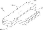
도 11 및 12는 실질적으로 강성 재료로 제조된 것을 제외하고는 도 9의 슬러리 분배기 (420)와 유사한 다른 실시양태의 슬러리 분배기 (620)를 도시한다. 도 11의 슬러리 분배기 (620)는 두-부품 구조를 가진다. 슬러리 분배기 상부품 (621)은 프로파일 시스템 (32)을 수용하는 홈 (627)을 포함한다. 상부품 (621) 및 쌍을 이루는 하부품 (623) 연결을 용이하게 하기 위한 장착 홀 (629)이 제공된다. 도 11의 슬러리 분배기 (620) 내부 구조는 도 9의 슬러리 분배기 (420)와 유사하고, 동일 부품에 동일 도면 번호가 사용된다.Figures 11 and 12 illustrate
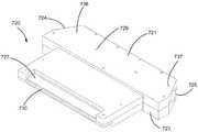
도 13-15를 참조하면, 본 발명에 따른 다른 실시양태의 슬러리 분배기 (720)가 도시된다. 도 13의 슬러리 분배기 (720)는 도 13의 슬러리 분배기 (720) 제1 및 제2 공급 유입구 (724, 725) 및 제1 및 제2 진입 구역 (736, 737)이 종축 또는 기계 방향 (50)에 대하여 약 60°의 공급각 θ에 위치하는 것 (도 14 참조)을 제외하고는 도 9의 슬러리 분배기 (420) 및 도 11의 분배기 (620)과 유사하다.Referring to Figs. 13-15, a
슬러리 분배기 (720)는 상부품 (721) 및 쌍을 이루는 하부품 (723)을 포함한 두-부품 구조로 구성된다. 슬러리 분배기 (720)의 두 부품들 (721, 723)은 임의의 적합한 방법, 예를들면 각각의 부품 (712, 723)에 제공되는 상응되는 개수의 장착 홀 (729)을 통한 파스너를 사용하여 서로 결합될 수 있다. 슬러리 분배기 (720) 상부품 (721)은 프로파일 시스템 (32)을 수용하는 홈 (727)을 포함한다. 도 13의 슬러리 분배기 (720)는 도 9 슬러리 분배기 (420) 및 도 11 슬러리 분배기 (620)의 다른 측면들에서 유사하다.The
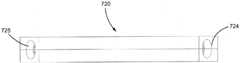
도 16 및17을 참조하면, 도 13의 슬러리 분배기 (720) 하부품 (723)이 도시된다. 하부품 (723)은 도 13의 슬러리 분배기 (720) 내부 구조의 제1 부 (731)를 형성한다. 상부품은 내부 구조의 대칭적 제2 부를 형성하여 상부품 및 하부품 (721, 723)은 서로 쌍으로 결합하여, 도 13의 슬러리 분배기 (720)의 완전한 내부 구조를 형성한다.Referring to Figures 16 and 17, the
도 16을 참조하면, 제1 및 제2 형상 덕트 (741, 743)는 제1 및 제2 공급 유동 방향 (790, 791)의 슬러리의 제1 및 제2 유체를 수용하고 슬러리 유동 방향을 방향각 α 변화만큼 변경하여 슬러리의 제1 및 제2 유체는 기계 방향 또는 종축 (50)과 정렬되는 실질적으로 유출구 유동 방향 (792)인 분배 도관 (728)으로 이송된다.Referring to Figure 16, the first and second shaped
도 18 및 19는 외측 및 내측 안내채널 (767, 768) 단면적이 제2 유체 방향 (797)에서 분배 유출구 (730)를 향할 때 점차 작아지는 것을 보인다. 외측 안내채널 (767)은 실질적으로 제2 형상 덕트 (743) 외벽 (757) 및 분배 도관 (728) 측벽 (753)을 따라 분배 유출구 (730)로 연장된다. 내측 안내채널 (768)은 제2 형상 덕트 (743) 내벽 (758)에 인접하고 이분기 커넥터 구역 (739)의 피크 (775)에서 종료된다.FIGS. 18 and 19 show that the cross-sectional area of the outer and
도 20을 참조하면, 일 실시태양인 석고 슬러리 혼합 및 분배 조립체 (810)는 도 13 슬러리 분배기 (720)와 유체 연통되는 석고 슬러리 혼합기 (812)를 포함한다. 석고 슬러리 혼합기 (812)는 수성 소성석고 슬러리를 형성하기 위하여 물 및 소성석고를 교반한다. 물 및 소성석고 모두는 당업계에 공지된 바와 같이하나 이상의 유입구를 통하여 혼합기 (812)에 공급된다. 임의의 적합한 혼합기가 슬러리 분배기와 함께 적용될 수 있다.Referring to Figure 20, an embodiment of gypsum slurry mixing and dispensing
슬러리 분배기 (720)는 석고 슬러리 혼합기 (812)와 유체 연통된다. 슬러리 분배기 (720)는 석고 슬러리 혼합기 (812)로부터 제1 공급 방향 (790)의 수성 소성석고 슬러리 제1 유체를 수용하는 제1 공급 유입구 (724), 석고 슬러리 혼합기 (812)로부터 제2 공급 방향 (791)의 수성 소성석고 슬러리 제2 유체를 수용하는 제2 공급 유입구 (725), 및 제1 및 제2 공급 유입구 (724, 725) 모두와 유체 연통되고 실질적으로 기계 방향 (50)을 따라 수성 소성석고 슬러리의 제1 유체 및 제2 유체를 슬러리 분배기 (720)로부터 방출하는 분배 유출구 (730)를 포함한다.The
슬러리 분배기 (720)는 분배 도관 (728)과 유체 연통되는 공급 도관 (722)을 포함한다. 공급 도관은 제1 공급 유입구 (724) 및 이와 이격되는 제2 공급 유입구 (725)을 포함하고, 이들 모두는 기계 방향 (50)에 대하여 약60° 공급각 θ으로 배치된다. 공급 도관 (722)은 제1 및 제2 공급 유동 방향 (790, 791)의 슬러리의 제1 및 제2 유체를 수용하여 방향각 α 변화 (도 16 참조) 만큼 슬러리 유동 방향을 변경시켜 슬러리의 제1 및 제2 유체가 실질적으로 기계 방향 (50)과 정렬되는 실질적으로 유출구 유동 방향 (792)인 분배 도관 (728)으로 이송시킨다.The
분배 도관 (728)은 실질적으로 횡축 (60)에 수직인 종축 또는 기계 방향 (50)을 따라 대략 연장된다. 분배 도관 (728)은 진입부 (752) 및 분배 유출구 (730)를 포함한다. 진입부 (752)는 공급 도관 (722)의 제1 및 제2 공급 유입구 (724, 725)와 유체 연통되어 진입부 (752)는 수성 소성석고 슬러리의 제1 및 제2 유체 모두를 이로부터 수용한다. 분배 유출구 (730)는 진입부 (752)와 유체 연통된다. 분배 도관 (728)의 분배 유출구 (730)는 횡축 (60)을 따라 소정 길이 연장되어 교차-기계 방향 또는 횡축 (60)의 수성 소성석고 슬러리의 조합된 제1 유체 및 제2 유체의 방출을 용이하게 한다.The
이송 도관 (814)은 석고 슬러리 혼합기 (812) 및 슬러리 분배기 (720) 사이에서 유체 연통되도록 구성된다. 이송 도관 (814)은 주 이송 통로 (815), 슬러리 분배기 (720) 제1 공급 유입구 (724)와 유체 연통되는 제1 이송 분기 (817), 및 슬러리 분배기 (720) 제2 공급 유입구 (725)와 유체 연통되는 제2 이송 분기 (818)를 포함한다. 주 이송 통로 (815)는 제1 및 제2 이송 분기 (817, 818) 모두와 유체 연통된다.The
수성 기포 공급 도관 (821)은 최소한 하나의 석고 슬러리 혼합기 (812) 및 이송 도관 (814)과 유체 연통된다. 공급원으로부터 수성 기포는 혼합기 (812) 하류 임의의 적합한 지점 및/또는 혼합기 (812) 자체에 있는 기포 공급 도관 (821)를 통하여 구성 재료들에 첨가되어 기포화 석고 슬러리를 형성하고 이것은 슬러리 분배기 (720)로 제공된다.The aqueous
주 이송 통로 (815)는 적합한 Y-형상의 유체 분할기 (819)를 통하여 제1 및 제2 이송 분기 (817, 818)와 결합된다. 유체 분할기 (819)는 주 이송 통로 (815) 및 제1 이송 분기 (817) 사이 및 주 이송 통로 (815) 및 제2 이송 분기 (818) 사이에 배치된다. 일부 실시양태들에서, 유체 분할기 (819)는 석고 슬러리의 제1 및 제2 유체를 실질적으로 균등하게 분할한다. 다른 실시양태들에서, 추가 요소들이 포함되어 슬러리의 제1 및 제2 유체 조절에 조력할 수 있다.The
사용에 있어서, 수성 소성석고 슬러리가 혼합기 (812)에서 배출된다. 혼합기 (812)에서 배출된 수성 소성석고 슬러리는 유체 분할기 (819)에서 수성 소성석고 슬러리의 제1 유체 및 수성 소성석고 슬러리의 제2 유체로 갈라진다. 혼합기 (812)에서 나온 수성 소성석고 슬러리는 실질적으로 균형있게 수성 소성석고 슬러리의 제1 유체 및 제2 유체로 분할된다.In use, an aqueous fired gypsum slurry is discharged from the
도 20의 석고 슬러리 혼합 및 분배 조립체 (810)는 도 6의 석고 슬러리 혼합 및 분배 조립체 (110)와 다른 측면들에서 유사하다. 본 발명에 따른 슬러리 분배기는 본원에 기재된 석고 슬러리 혼합 및 분배 조립체의 다른 실시태양들에서도 적용될 수 있다.The gypsum slurry mixing and dispensing
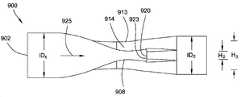
도 21을 참조하면, 본 발명에 따른 석고 슬러리 혼합 및 분배 조립체에 사용하기 적합한 일 실시양태의 Y-형상의 유체 분할기 (900)가 도시된다. 유체 분할기 (900)는 석고 슬러리 혼합기 및 슬러리 분배기와 유체 연통되도록 배치되어 유체 분할기 (900)는 혼합기로부터 단일 수성 소성석고 슬러리 유체를 수용하여 별개의 두 수성 소성석고 슬러리 유체들을 슬러리 분배기의 제1 및 제2 공급 유입구로 방출한다. 하나 이상의 유량-변경 요소가 혼합기 및 유체 분할기 (900) 사이 및/또는 분할기 (900)로 이어지는 하나 또는 양 이송 분기 및 연결 슬러리 분배기 사이에 배치된다.21, a Y-shaped
유체 분할기 (900)는 단일 슬러리 유체를 수용하는 주 분기 (903)에 위치하는 실질적으로 원형인 유입구 (902) 및 분할기 (900)로부터 두 슬러리 유체를 방출시키는 제1 및 제2 유출구 분기 (905, 907) 각각에 위치하는 한 쌍의 실질적으로 원형인 유출구 (904, 906)를 가진다. 유입구 (902) 및 유출구 (904, 906) 개구 단면적은 원하는 유속에 따라 달라진다. 유출구 (904, 906) 개구 단면적이 유입구 (902) 개구 단면적 각각과 실질적으로 동일한 실시태양들에서, 유입구 (902) 및 양 유출구 (904, 906)의 체적유량은 실질적으로 동일하고 각각의 유출구 (904, 906)에서 배출되는 슬러리 유속은 유입구 (902)로 들어가는 단일 슬러리 유체 속도의 약 50%로 감소된다.The
일부 실시양태들에서, 유출구 (904, 906) 직경은 유입구 (902) 직경보다 작아 상대적으로 높은 유속을 유지하며 분할기 (900)를 통과할 수 있다. 유출구 (904, 906) 개구 단면적 각각이 유입구 (902) 개구 단면적보다 작은 실시태양들에서, 유출구 (904, 906) 및 유입구 (902) 모두가 실질적으로 동일한 단면적을 가지는 경우보다 유출구 (904, 906)에서 유속은 유지되거나 더 낮게 감소된다. 예를들면, 일부 실시양태들에서, 유체 분할기 (900)의 유입구 (902) 내경 (ID1)은 약 3 인치, 및 각각의 유출구 (904, 906) ID2 은 약 2.5 인치이다 (다른 유입구 및 유출구 직경들이 다른 실시양태들에서 적용될 수 있다). 라인 속도 350 fpm에서 이러한 치수를 가지는 실시태양에서, 유출구 (904, 906) 직경이 작아지면 유출구에서 유속은 유입구 (902)에서 단일 슬러리 유체 유속의 약 25%까지 감소된다.In some embodiments, the diameters of the
유체 분할기 (900)는 제1 및 제2 유출구 분기 (905, 907) 사이 오목 중앙부 (914) 및 접합부 (920)를 포함한다. 오목 중앙부 (914)는 접합부 (920) 상류에서 유체 분할기 (900) 중앙 내부에 제한부 (908)를 형성시키며 분할기 외측 에지 (910, 912)로 유동을 촉진시켜 접합부 (920)에서 슬러리 축적 발생을 감소시킨다. 오목 중앙부 (914) 형상으로 유체 분할기 (900) 외측 에지 (910, 912)에 인접한 안내채널 (911, 913)이 형성된다. 오목 중앙부 (914)에 있는 제한부 (908) 높이 H2 는 안내채널 (911, 913) 높이 H3 보다 작다. 안내채널 (911, 913) 단면적은 중앙 제한부 (908) 단면적보다 크다. 그 결과, 유동 슬러리는 중앙 제한부 (908)를 통과할 때보다 안내채널 (911, 913)을 통과할 때 유동 저항성이 낮고, 유체는 분할기 접합부 (920) 외측 에지를 향한다.The
접합부 (920)는 제1 및 제2 유출구 분기 (905, 907) 개구를 형성한다. 접합부 (920)는 유입구 유동 방향 (925)에 실질적으로 수직인 평탄 벽면 (923)으로 이루어진다.The
도 23을 참조하면, 일부 실시양태들에서, 조정가능하고 규칙적인 시간 간격으로 분할기 (900)를 압착하는 자동화 기구 (950)가 제공되어 분할기 (900) 내부에서 고체 축적을 방지한다. 일부 실시양태들에서, 압착 기구 (950)는 오목 중앙부 (914)의 반대측 (942, 943)에 배치되는 한 쌍의 플레이트 (952, 954)를 포함한다. 플레이트 (952, 954)는 적합한 구동기 (960)에 의해 서로에 대하여 이동 가능하다. 구동기 (960)는 자동으로 또는 선택적으로 작동되어 플레이트 (952, 954)를 서로에 대하여 이동시켜 분할기 (900)의 오목 중앙부 (914) 및 접합부 (920)에 압축력을 인가한다.Referring to Figure 23, in some embodiments, an
압착 기구 (950)가 유체 분할기를 압축하면, 압착 작용으로 유체 분할기 (900)에 압축력이 인가되고, 이에 대하여 안쪽으로 눌려진다. 본 압축력으로 유출구 (904, 906)를 통한 실질적으로 균등한 슬러리 분배를 방해할 수 있는 분할기 (900) 내부 고체 축적을 방지할 수 있다. 일부 실시양태들에서, 압착 기구 (950)는 구동기에 의해 작동 가능한 프로그램화 제어기를 사용하여 자동으로 주기적으로 작동될 수 있다. 압착 기구 (950)에 의한 압축력 인가 시간 구간 및/또는 주기적 작동 간격은 조정될 수 있다. 또한, 압축 방향으로 플레이트 (952, 954)가 서로에 대하여 주행하는 행정 길이는 조정될 수 있다.When the
슬러리 분배기, 석고 슬러리 혼합 및 분배 조립체, 및 이를 이용한 방법의 실시태양들이 본원에 제공되고 이들은 상업적인 석고 벽판 제조에 많은 유용한 공정 특징부들을 제공한다. 본 발명에 따른 슬러리 분배기로 인하여 이동 커버시트 웨브가 제조 라인 습식단에 있는 혼합기를 지나 성형 스테이션을 향할 때 이동 커버시트 상으로 수성 소성석고 슬러리를 용이하게 확산시킬 수 있다.Embodiments of a slurry dispenser, a gypsum slurry mixing and dispensing assembly, and a method using the same are provided herein and provide many useful process features for commercial gypsum wall manufacture. The slurry dispenser according to the present invention allows the aqueous fired gypsum slurry to readily diffuse onto the moving cover sheet as the moving cover sheet web passes through the mixer at the wet end of the production line and faces the forming station.
본 발명에 따른 석고 슬러리 혼합 및 분배 조립체는 혼합기로부터 수성 소성석고 슬러리 유체를 별도의 수성 소성석고 슬러리 두 유체들로 분할할 수 있고 이들은 본 발명에 따른 슬러리 분배기 하류에서 재조합되어 원하는 확산 패턴을 제공한다. 이중 유입구 구성 및 분배 유출구 설계로 인하여 교차-기계 방향에 있는 높은 점성의 슬러리를 이동 커버시트 웨브 상에 더욱 넓게 확산시킬 수 있다. 슬러리 분배기는 별도의 수성 소성석고 슬러리 두 유체들이 교차-기계 방향 성분을 포함한 공급 유입구 방향을 따라 슬러리 분배기로 진입하고, 슬러리 분배기 내에서 슬러리 두 유체는 실질적으로 기계 방향으로 이동되도록 방향이 변경되고, 슬러리 분배기의 분배 유출구에서 배출되는 수성 소성석고 슬러리의 조합 유체의 교차-?항 균일성을 개선하여 횡축 또는 교차 기계 방향을 따라 시간에 따른 질량 유동 변동을 감소시키는 방향으로 분배기 내에서 다시 조합되도록 구성된다. 교차-기계 방향 성분을 포함한 제1 및 제2 공급 방향의 수성 소성석고 슬러리의 제1 유체 및 제2 유체를 도입하면 운동량 및/또는 에너지가 감소된 상태로 슬러리의 재-조합 유체가 슬러리 분배기로부터 방출될 수 있다.The gypsum slurry mixing and dispensing assembly according to the present invention can separate the aqueous fired gypsum slurry fluid from the mixer into two separate aqueous fired gypsum slurry two fluids which are recombined downstream of the slurry dispenser according to the present invention to provide the desired diffusion pattern . The dual inlet configuration and distribution outlet design allows the highly viscous slurry in the cross-machine direction to be spread more widely on the moving cover sheet web. The slurry dispenser is configured such that a separate aqueous fired gypsum slurry two fluids enter the slurry dispenser along the feed inlet direction containing the cross-machine direction components and the slurry in the slurry dispenser is redirected so that the two fluids are substantially moved in the machine direction, The composition of the aqueous fired gypsum slurry discharged from the distribution outlet of the slurry dispenser is improved to improve the cross-homogeneity of the fluid so that it can be recombined in the distributor in the direction of decreasing the mass flow fluctuation with time along the transverse or cross machine direction do. The introduction of the first fluid and the second fluid of the aqueous firing gypsum slurry in the first and second supply directions including the cross-machine direction component causes the re-combination fluid of the slurry to flow from the slurry distributor with reduced momentum and / Can be released.
슬러리 유체들 각각이 슬러리 분배기를 층류 상태로 이동되도록 슬러리 분배기 내부 유로가 구성된다. 슬러리 유체들 각각이 슬러리 분배기를 최소 또는 실질적으로 공기-액상 슬러리 상분리 없는 상태로 이동되도록 슬러리 분배기 내부 유로가 구성된다. 슬러리 유체들 각각이 슬러리 분배기를 실질적으로 와류 형성 없는 상태로 이동되도록 슬러리 분배기 내부 유로가 구성된다.The slurry distributor internal flow path is configured so that each of the slurry fluids is moved to the laminar flow state of the slurry distributor. The slurry distributor internal flow path is configured so that each of the slurry fluids is moved to a minimum or substantially no air-liquid slurry phase separation state of the slurry distributor. The slurry distributor internal flow path is constituted such that each of the slurry fluids is moved in a state in which the slurry distributor is substantially not vortex-formed.
본 발명에 따른 석고 슬러리 혼합 및 분배 조립체는 슬러리 분배기의 분배 유출구 상류에 유로 구조를 포함하여 슬러리 속도를 하나 이상의 단계로 감속시킨다. 예를들면, 유체 분할기가 혼합기 및 슬러리 분배기 사이에 제공되어 슬러리 분배기에 들어가는 슬러리 속도를 낮출 수 있다. 다른 예시로서, 석고 슬러리 혼합 및 분배 조립체의 유로 구조는 슬러리 분배기 내부에서 상류 확대 면적을 포함하여 슬러리를 서행시켜 슬러리 분배기의 분배 유출구로부터 배출될 때 조정될 수 있다.The gypsum slurry mixing and dispensing assembly according to the present invention includes a flow path structure upstream of the distribution outlet of the slurry dispenser to reduce the slurry speed to one or more stages. For example, a fluid divider may be provided between the mixer and the slurry dispenser to lower the slurry rate entering the slurry dispenser. As another example, the flow path structure of the gypsum slurry mixing and dispensing assembly can be adjusted when the slurry is slowed down, including the upstream enlargement area, within the slurry dispenser and discharged from the dispensing outlet of the slurry dispenser.
또한 분배 유출구의 구조는 슬러리 분배기에서 이동 커버시트 웨브 상으로 배출될 때 슬러리 배출 속도 및 운동량을 제어할 수 있다. 슬러리 분배기 유로 구조는 분배 유출구로부터 배출되는 슬러리가 실질적으로 2-차원 유동패턴을 유지하도록 교차-기계 방향의 더 넓은 유출구 대비 상대적으로 낮은 높이로 구성되어 안정성 및 균일성을 개선시킨다.The structure of the distribution outlet can also control the slurry discharge rate and momentum as it is discharged from the slurry dispenser onto the moving cover sheet web. The slurry distributor flow path structure is configured to have a relatively low height relative to a wider outlet in the cross-machine direction so that the slurry discharged from the distribution outlet maintains a substantially two-dimensional flow pattern to improve stability and uniformity.
상대적으로 광폭의 방출 유출구는 분배 유출구에서 배출되는 슬러리의 단위 폭 당 운동량을 유사한 운전 조건들의 종래 부트에서 배출되는 슬러리의 단위 폭 당 운동량 보다 더욱 낮도록 설정한다. 단위 폭 당 감소된 운동량은 슬러리가 슬러리 분배기로부터 웨브에 배출되는 지점 상류에서 커버 시트재료 웨브에 인가된 농후층의 스킴 코트를 워시아웃하는 것을 방지한다.The relatively wide discharge outlet sets the momentum per unit width of the slurry discharged from the distribution outlet to be lower than the amount of momentum per unit width of the slurry discharged from a conventional boot of similar operating conditions. The reduced momentum per unit width prevents wash-out of the rich coat layer coat applied to the cover sheet material web upstream of the point at which the slurry is discharged from the slurry dispenser into the web.
종래 부트 유출구 폭이 6 인치이고 두께가 2 인치인 경우, 대량생산에 있어서 유출구의 평균속도는 761 ft/분. 분배 유출구 개구 폭이 24 인치이고 두게가 0.75 인치인 본 발명에 따른 슬러리 분배기의 실시태양들에서, 평균속도는550 ft/분이다. 질량 유동속도는 두 장치에 있어서 3,437 lb/분로 동일하다. 두 경우에서 슬러리 운동량 (질량 유동속도*평균속도)은 종래 부트 및 슬러리 분배기 각각에 대하여 ~2,618,000 및 1,891,000 lb·ft/분2 이다. 각각의 계산 운동량을 종래 부트 유출구 및 슬러리 분배기 유출구의 폭으로 나누면, 종래 부트에서 배출되는 슬러리 단위폭 당 운동량은 402,736 (lb·ft/분2)/(부트 폭을 횡단 인치)이고, 본 발명에 따른 슬러리 분배기에서 배출되는 슬러리 단위폭 당 운동량은 78,776 (lb·ft/분2)/(슬러리 분배기 폭 횡단 인치)이다. 이 경우, 슬러리 분배기에서 배출되는 슬러리는 종래 부트 대비 단위 폭 당 약 20%의 운동량을 가진다.With a conventional boot outlet width of 6 inches and a thickness of 2 inches, the average speed of the outlet in mass production is 761 ft / min. In embodiments of the slurry dispenser according to the present invention wherein the distribution outlet opening width is 24 inches and the sump is 0.75 inches, the average velocity is 550 ft / min. The mass flow rate is the same at 3,437 lb / min for both devices. In both cases, the slurry momentum (mass flow rate * mean velocity) is ~ 2,618,000 and 1,891,000 lb · ft / min2 for each conventional boot and slurry dispenser. Dividing the respective calculated momentum by the width of the conventional boot outlet and the outlet of the slurry distributor, the momentum per slurry unit width discharged from the conventional boot is 402,736 (lb · ft / min2 ) / (width across the boot width) The momentum per slurry discharged from the slurry distributor is 78,776 (lb · ft / min2 ) / (slurry distributor width across inches). In this case, the slurry discharged from the slurry dispenser has a momentum of about 20% per unit width of the conventional boots.
상대적으로 낮은 WSR 또는 더욱 통상적인 WSR, 예를들면, 물-대-소성석고 비율이 약 0.4 내지 약 1.2, 예를들면, 일부 실시양태들에서 0.75 이하, 및 다른 실시양태들에서 약 0.4 내지 약 0.8 범위를 포함한 넓은 범주의 물 -스투코 비율의 수성 소성석고 슬러리를 사용하면서도 본 발명에 따른 슬러리 분배기는 원하는 확산패턴을 달성할 수 있다. 본 발명에 따른 슬러리 분배기의 실시태양들은 제1 및 제2 유체가 제1 및 제2 공급 유입구로부터 슬러리 분배기를 통하여 분배 유출구로 진행할 때 수성 소성석고 슬러리의 제1 유체 및 제2 유체에 대한 전단 효과가 제어되도록 구성된 내부 유로를 포함한다. 슬러리 분배기에서 전단력을 제어하면 이러한 전단력 결과로 선택적으로 슬러리 점도를 감소시킬 수 있다. 슬러리 분배기에서 전단력 제어 효과로, 더욱 낮은 물 -스투코 비율을 가지는 슬러리는 통상의 WSR을 가지는 슬러리와 동등한 교차-기계 방향에서의 확산 패턴으로 슬러리 분배기에서 배출된다.A relatively low WSR or more conventional WSR, e.g., a water-to-calcined gypsum ratio of from about 0.4 to about 1.2, such as 0.75 or less in some embodiments, and from about 0.4 to about 1.2 in other embodiments A slurry dispenser according to the present invention can achieve a desired diffusion pattern while using a water-stucco-ratio aqueous-based gypsum slurry of a wide range including the range of 0.8 to 0.8. Embodiments of the slurry dispenser in accordance with the present invention provide a shear effect for the first fluid and the second fluid of the aqueous fired gypsum slurry when the first and second fluids proceed from the first and second feed inlets through the slurry distributor to the distribution outlet, Is controlled to be controlled. Control of the shear force in the slurry dispenser can selectively reduce the slurry viscosity as a result of this shear force. As a shear force control effect in the slurry dispenser, the slurry with a lower water-to-stoichiometric ratio is discharged from the slurry dispenser with a diffusion pattern in the cross-machine direction equivalent to that of a slurry with normal WSR.
슬러리 분배기 내부 유로 구조는 다양한 물 -스투코 비율을 가지는 슬러리를 수용하여 슬러리 분배기 내부 구조 경계벽 구역에 인접하여 유동을 증가시키도록 구성된다. 경계벽 층들 주위로 유동도가 증가되도록 슬러리 분배기 유로 구조 특징부를 도입함으로써, 슬러리가 슬러리 분배기에서 재-순환 및/또는 유동 정지 및 내부 응결되는 경향이 감소된다. 따라서, 이 결과 슬러리 분배기 내부에서응결 슬러리 축적이 감소된다.The slurry distributor internal flow path structure is configured to receive a slurry having various water-to-stoichiometric ratios to increase flow adjacent the slurry distributor internal structure boundary wall area. By introducing the slurry distributor flow path features to increase the flow rate around the perimeter wall layers, the tendency of the slurry to re-circulate and / or flow stop and internal set in the slurry dispenser is reduced. Thus, condensation slurry accumulation within the resulting slurry dispenser is reduced.
본 발명에 따른 슬러리 분배기는 분배 유출구에 인접하게 장착되고 분배 유출구에서 배출되는 슬러리의 조합된 유체들의 교차 기계 속도 성분을 가변시키는 프로파일 시스템을 포함하여 선택적으로 성형 스테이션을 향하는 제로 라인으로 하향되는 기질에 교차 기계 방향의 슬러리 확산 각도 및 폭을 제어할 수 있다. 프로파일 시스템은 분배 유출구에서 배출되는 슬러리가 슬러리 점도 및 WSR에 덜 민감하면서도 원하는 확산 패턴을 달성하도록 조력한다. 프로파일 시스템은 슬러리 분배기의 분배 유출구에서 배출되는 슬러리의 유체 동력을 변화시켜 슬러리가 교차-기계 방향에서 더욱 균일한 속도를 가지도록 슬러리 유동을 안내한다. 또한 프로파일 시스템을 적용하면 본 발명에 따른 석고 슬러리 혼합 및 분배 조립체는 상이한 유형 및 규모의 벽판 제조를 위한 석고 벽판 제조 설비에 적용될 수 있다.The slurry dispenser according to the present invention comprises a profile system mounted adjacent to the dispensing outlet and varying the cross-machine speed component of the combined fluids of the slurry discharged from the dispensing outlet, and optionally to a substrate downwardly directed towards the forming station The slurry diffusion angle and width in the cross machine direction can be controlled. The profile system assists the slurry discharged from the distribution outlet to achieve the desired diffusion pattern while being less sensitive to slurry viscosity and WSR. The profile system changes the fluid power of the slurry discharged from the distribution outlet of the slurry dispenser to guide the slurry flow so that the slurry has a more uniform velocity in the cross-machine direction. Also with the application of the profile system, the gypsum slurry mixing and dispensing assembly according to the present invention can be applied to a gypsum board manufacturing facility for the manufacture of wall panels of different types and sizes.
본원에 인용된 공개문헌, 특허출원, 및 특허를 포함한 모든 참고문헌들은 각각의 참고문헌이 개별적으로 및 특정하게 본원에 참고문헌으로 포함되고 전체가 본원에 제시되는 것과 동일한 정도로 본원에 참고문헌으로 포함된다.All references, including publications, patent applications, and patents, cited herein, are hereby incorporated by reference to the same extent as if each reference was specifically and individually indicated to be incorporated herein by reference, do.
달리 본원에 명시되거나 명백하게 문맥상 반대로 해석되지 않는 한 본 발명을 기술하는 문맥상 (특히 하기 청구범위 문맥상) 용어 “a” 및 “an” 및 “the” 및 유사한 지시어는 단수 및 복수 모두를 포함하는 것으로 해석되어야 한다. 달리 언급되지 않는 한 용어 “구성되는”, “가지는”, “포함하는”, 및 “함유하는”은 확장-가능한 용어 (즉, “포함하지만 제한되지 않는” 의미)로 해석되어야 한다. 달리 본원에 명시되지 않는 한 본원에서 수치 범위를 언급하는 것은 범위에 속하는 각각의 분리된 수치들을 개별적으로 언급하기 위한 간단한 방법으로 의도된 것이고, 각각의 분리 수치는 본원에서 개별적으로 언급되는 것과 같이 본 명세서에 포함된다. 달리 본원에 명시되거나 달리 명백하게 문맥상 반대로 해석되지 않는 한 본원에 기재된 모든 방법은 임의의 적합한 순서로 구현될 수 있다. 본원에 제공된 임의의 및 모든 예시들, 또는 예시적 용어 (예를들면, “예를들면”)는 단지 본 발명을 양호하게 설명하기 위한 의도이고 달리 주장되지 않는 한 본 발명의 범위를 제한하는 것은 아니다. 어떠한 명세서 언어도 본 발명을 구현하기 위한 필수 요소로서 임의의 비-청구 요소를 의미하는 것으로 해석되어서는 않된다.The terms "a" and "an" and "the" and similar referents in the context of describing the invention (especially in the context of the following claims) include both singular and plural unless otherwise stated or clearly contradicted by context Should be interpreted as Unless otherwise stated, the terms " comprising, " " having, " " including, " and " containing " are to be construed as an expandable term (i.e. Unless otherwise stated herein, reference to a numerical range in this disclosure is intended to be a simple method for individually addressing each of the discrete numerical values falling within the scope, and each discrete numerical value is referred to herein, Are included in the specification. All of the methods described herein may be implemented in any suitable order unless otherwise stated or otherwise clearly contradicted by context. It is to be understood that any and all examples, or exemplary language (e.g., " as ") provided herein are merely intended to illustrate the present invention well and that the present invention, no. No language is to be construed as indicating any non-claimed element as an essential element for implementing the invention.
본 발명을 구현하기 위하여 본 발명자에게 알려진 최적 형태를 포함한 본 발명의 바람직한 실시태양들이 본원에 기재된다. 바람직한 실시태양들 변경은 상기 상세한 설명을 독취한 당업자에게 명백하여 질 것이다. 본 발명자는 기술자들이 이러한 명백한 변형을 이용할 것을 예상하고, 본 발명자는 본원에 특히 기재된 것 외에도 본 발명이 구현될 것을 의도한다. 따라서, 본 발명은 적용 법률이 허용하는 한 첨부된 청구범위에 언급된 주제의 모든 변형 및 균등론을 포함한다. 또한, 달리 본원에 명시되거나 달리 명백하게 문맥상 반대로 해석되지 않는 한 모든 잠재적 변형에서 상기 요소들의 임의의 조합 역시 본 발명에 의해 포괄된다.Preferred embodiments of the present invention, including the best mode known to the inventors for implementing the present invention, are described herein. Modifications of the preferred embodiments will become apparent to those skilled in the art upon a reading of the above detailed description. The inventors contemplate that the artisan will make use of these apparent variations and the inventors contemplate that the invention will be implemented in addition to those specifically described herein. Accordingly, the invention includes all modifications and equivalents of the subject matter recited in the appended claims, as may be permitted by applicable law. Also, any combination of the above elements in all potential variations is encompassed by the present invention, unless otherwise specified or otherwise clearly contradicted by context.
Claims (20)
Translated fromKorean종축을 따라 연장되고, 진입부 및 공급 도관의 제1 및 제2 공급 유입구와 유체 연통되는 진입부와 유체 연통되고 종축과 수직인 횡축을 따라 소정 길이 연장되는 분배 유출구를 포함하는 분배 도관을 포함하며,
제1 및 제2 공급 유입구는 각각 단면적을 가지는 개구를 가지고,
분배 유출구는 유출구 개구를 포함하며,
유출구 개구는 제1 및 제2 공급 유입구의 개구 단면적의 합보다 큰 단면적을 가지고 횡축을 따르는 폭 및 종축 및 횡축과 서로 수직한 수직축을 따르는 높이를 가지며,
유출구 개구의 폭-대-높이 비율은 4 이상인, 슬러리 분배기.
A supply conduit including a first entry region having a first feed inlet and a second entry region having a second feed inlet being spaced apart from the first feed inlet; And
And a dispensing conduit extending along the longitudinal axis and including a dispensing outlet having a length extending along a transverse axis in fluid communication with the entry portion in fluid communication with the first and second feed inlets of the entry portion and the feed conduit and perpendicular to the longitudinal axis, ,
The first and second supply inlets each have an opening having a cross-sectional area,
The dispensing outlet includes an outlet opening,
The outlet opening has a cross-sectional area greater than the sum of the open cross-sectional areas of the first and second supply inlets and has a width along the transverse axis and a height along a vertical axis perpendicular to the longitudinal and transverse axis,
Wherein the width-to-height ratio of the outlet opening is at least 4.
2. The slurry dispenser of claim 1, wherein the first and second feed inlets and the first and second entry zones are each arranged in a feed angle range of up to 135 degrees with respect to the longitudinal axis.
The slurry dispenser of claim 1, wherein the supply conduit extends along a transverse axis.
3. A method according to claim 1 or claim 2, wherein the feed conduit is arranged to direct the first fluid of the slurry passing through the first feed inlet and the first entry zone in the first feed flow direction to the outlet flow direction To a slurry dispenser.
3. The apparatus of claim 1 or 2, wherein the supply conduit comprises this branch connector section comprising first and second guide surfaces, each of the first and second guide surfaces passing through a first supply inlet and a first inlet section The first fluid of the slurry moving in the first feed flow direction is changed in the direction of the outlet flow to an angle range of up to 135 degrees and the slurry flowing in the second feed flow direction through the second feed inlet and the second entry area, Of the second fluid in the direction of the outlet flow to a directional angular range of up to < RTI ID = 0.0 > 135. ≪ / RTI >
3. The slurry dispenser of claim 1 or 2, wherein the supply conduit comprises a guide channel having a wider cross-sectional area than the proximal portion and disposed adjacent the wall surface such that the slurry fluid passes therethrough.
3. The apparatus of claim 1 or 2, wherein the at least one supply conduit and the distribution conduit include an enlarged area having a flow cross-sectional area wider than the flow cross-sectional area of the area upstream of the enlarged area in the direction from the supply conduit toward the distribution conduit Slurry dispenser.
3. The method of claim 1 or 2, wherein the distribution conduit has a height lower than the adjacent zone height to increase the local shear force applied to the fluid of the aqueous fired gypsum slurry passing through the convergent portion compared to the local shear force applied to the adjacent zone And a converging portion.
3. The slurry dispenser of claim 1 or 2, further comprising a profile system that varies the shape and / or size of the distribution outlet along the abscissa.
혼합기와 유체 연통되는 제1항에 의한 슬러리 분배기로 구성되고, 제1 공급 유입구는 석고 슬러리 혼합기로부터 수성 소성석고 슬러리의 제1 유체를 수용하고, 제2 공급 유입구는 혼합기로부터 수성 소성석고 슬러리의 제2 유체를 수용하고, 분배 유출구는 제1 및 제2 공급 유입구 모두와 유체 연통되어 수성 소성석고 슬러리의 제1 유체 및 제2 유체는 분배 유출구를 통과하여 슬러리 분배기로부터 방출되는, 석고 슬러리 혼합 및 분배 조립체.
A mixer for mixing water and calcined gypsum to form an aqueous fired gypsum slurry;
Wherein the first feed inlet receives a first fluid of the aqueous fired gypsum slurry from the gypsum slurry mixer and the second feed inlet receives the first fluid of the aqueous fired gypsum slurry from the mixer in fluid communication with the mixer, 2 fluid and the distribution outlet is in fluid communication with both the first and second feed inlets so that the first fluid and the second fluid of the aqueous fired gypsum slurry are discharged from the slurry distributor through the distribution outlet and the gypsum slurry mixing and distribution Assembly.
석고 슬러리 혼합기 및 슬러리 분배기 사이에 배치되고 이들과 유체 연통되고, 주 이송 통로 및 제1 및 제2 이송 분기를 포함하는 이송 도관;
주 이송 통로 및 제1 및 제2 이송 분기를 결합하고, 주 이송 통로 및 제1 이송 분기 사이 및 주 이송 통로 및 제2 이송 분기 사이에 배치되는 유체 분할기;를 더욱 포함하고,
제1 이송 분기는 슬러리 분배기의 제1 공급 유입구와 유체 연통되고, 제2 이송 분기는 슬러리 분배기의 제2 공급 유입구와 유체 연통되는, 석고 슬러리 혼합 및 분배 조립체.
11. The method of claim 10,
A transfer conduit disposed between and in fluid communication with the gypsum slurry mixer and the slurry dispenser, the transfer conduit comprising a main transfer passage and first and second transfer branches;
And a fluid splitter coupled to the main transfer passage and the first and second transfer branches and disposed between the main transfer passage and the first transfer branch and between the main transfer passage and the second transfer branch,
Wherein the first transfer branch is in fluid communication with the first feed inlet of the slurry dispenser and the second feed branch is in fluid communication with the second feed inlet of the slurry dispenser.
슬러리 분배기의 제2 공급 유입구를 통하여 수성 소성석고 슬러리의 제2 유체를 통과시키는 단계;
슬러리 분배기에서 수성 소성석고 슬러리의 제1 유체 및 제2 유체를 조합하는 단계; 및
수성 소성석고 슬러리의 제1 유체 및 제2 유체를 슬러리 분배기에서 이동 웨브 상으로 방출하는 단계로 구성되는, 기계 방향을 따라 이동되는 커버 시트재료 웨브 상에 수성 소성석고 슬러리를 분배하는 방법.
Passing a first fluid of the aqueous fired gypsum slurry through a first feed inlet of the slurry dispenser of claim 1;
Passing a second fluid of the aqueous fired gypsum slurry through a second feed inlet of the slurry dispenser;
Combining the first fluid and the second fluid of the aqueous fired gypsum slurry in a slurry dispenser; And
And discharging the first fluid and the second fluid of the aqueous fired gypsum slurry from the slurry dispenser onto a moving web. ≪ Desc / Clms Page number 20 >
13. The method of claim 12, wherein the combined first and second fluids of the aqueous fired gypsum slurry are discharged at an average flow rate, the cover sheet material web is moved at a web speed along the machine direction, and the ratio of the average flow rate to the web speed 2 or less.
14. A method according to claim 12 or 13, wherein the web has a width extending along a cross-machine direction perpendicular to the machine direction, the width of the outlet opening of the distribution outlet extending along the cross- Wherein the ratio of the outlet opening width of the dispensing outlet is from 1 to 6.
14. The method of claim 12 or 13, further comprising mixing water and fired gypsum in a water to gypsum weight ratio of 0.4 to 1.2 and stirring to form a first fluid and a second fluid of the aqueous fired gypsum slurry / RTI >
14. The method of claim 12 or 13, wherein the first fluid and the second fluid of the aqueous fired gypsum slurry discharged from the slurry distributor form a diffusion pattern on the moving web and adjust at least one of the size and shape of the distribution outlet And modifying the diffusion pattern.
14. The method of claim 12 or 13, wherein the first fluid and the second fluid of the aqueous fired gypsum slurry are combined in a slurry dispenser such that the combined first fluid and the second fluid of the aqueous fired gypsum slurry move in a dispensing direction along the longitudinal axis How.
혼합기에서 유출되는 수성 소성석고 슬러리를 수성 소성석고 슬러리의 제1 유체 및 수성 소성석고 슬러리의 제2 유체로 분할하는 단계를 더욱 포함하는, 방법.
14. The method of claim 12 or 13, further comprising: discharging the aqueous fired gypsum slurry from the mixer;
Further comprising dividing the aqueous fired gypsum slurry flowing out of the mixer into a first fluid of the aqueous fired gypsum slurry and a second fluid of the aqueous fired gypsum slurry.
Applications Claiming Priority (11)
| Application Number | Priority Date | Filing Date | Title |
|---|---|---|---|
| US201061428706P | 2010-12-30 | 2010-12-30 | |
| US201061428736P | 2010-12-30 | 2010-12-30 | |
| US61/428,736 | 2010-12-30 | ||
| US61/428,706 | 2010-12-30 | ||
| US201161550873P | 2011-10-24 | 2011-10-24 | |
| US201161550857P | 2011-10-24 | 2011-10-24 | |
| US201161550827P | 2011-10-24 | 2011-10-24 | |
| US61/550,827 | 2011-10-24 | ||
| US61/550,857 | 2011-10-24 | ||
| US61/550,873 | 2011-10-24 | ||
| PCT/US2011/068167WO2012092582A1 (en) | 2010-12-30 | 2011-12-30 | Slurry distributor, system and method for using same |
Publications (2)
| Publication Number | Publication Date |
|---|---|
| KR20140042774A KR20140042774A (en) | 2014-04-07 |
| KR101986713B1true KR101986713B1 (en) | 2019-06-07 |
Family
ID=45532037
Family Applications (1)
| Application Number | Title | Priority Date | Filing Date |
|---|---|---|---|
| KR1020137019326AExpired - Fee RelatedKR101986713B1 (en) | 2010-12-30 | 2011-12-30 | Slurry distributor, system and method for using same |
Country Status (13)
| Country | Link |
|---|---|
| US (2) | US9616591B2 (en) |
| EP (1) | EP2658695B1 (en) |
| JP (1) | JP6075787B2 (en) |
| KR (1) | KR101986713B1 (en) |
| CN (1) | CN103648738B (en) |
| AR (1) | AR085780A1 (en) |
| AU (1) | AU2011351955B2 (en) |
| BR (1) | BR112013016733A2 (en) |
| CA (1) | CA2823347C (en) |
| MX (1) | MX356602B (en) |
| MY (1) | MY171701A (en) |
| RU (1) | RU2599399C2 (en) |
| WO (1) | WO2012092582A1 (en) |
Families Citing this family (79)
| Publication number | Priority date | Publication date | Assignee | Title |
|---|---|---|---|---|
| US11338548B2 (en) | 2005-06-09 | 2022-05-24 | United States Gypsum Company | Light weight gypsum board |
| US11306028B2 (en) | 2005-06-09 | 2022-04-19 | United States Gypsum Company | Light weight gypsum board |
| US9802866B2 (en) | 2005-06-09 | 2017-10-31 | United States Gypsum Company | Light weight gypsum board |
| US9840066B2 (en) | 2005-06-09 | 2017-12-12 | United States Gypsum Company | Light weight gypsum board |
| AR084755A1 (en) | 2010-12-30 | 2013-06-05 | United States Gypsum Co | DISTRIBUTOR AND METHOD OF DISTRIBUTION OF MILK |
| MY171701A (en) | 2010-12-30 | 2019-10-23 | United States Gypsum Co | Slurry distributor, system and method for using same |
| US9296124B2 (en) | 2010-12-30 | 2016-03-29 | United States Gypsum Company | Slurry distributor with a wiping mechanism, system, and method for using same |
| US10076853B2 (en) | 2010-12-30 | 2018-09-18 | United States Gypsum Company | Slurry distributor, system, and method for using same |
| US9999989B2 (en) | 2010-12-30 | 2018-06-19 | United States Gypsum Company | Slurry distributor with a profiling mechanism, system, and method for using same |
| PL2771158T3 (en)* | 2011-10-24 | 2017-05-31 | United States Gypsum Company | Multiple-leg discharge boot for slurry distribution |
| RU2638666C2 (en) | 2011-10-24 | 2017-12-15 | Юнайтед Стэйтс Джипсам Компани | Suspension distributor and method for its use |
| MX353809B (en) | 2011-10-24 | 2018-01-30 | United States Gypsum Co | Multi-piece mold and method of making slurry distributor. |
| WO2013122974A1 (en) | 2012-02-17 | 2013-08-22 | United States Gypsum Company | Gypsum products with high efficiency heat sink additives |
| US9540810B2 (en) | 2012-10-23 | 2017-01-10 | United States Gypsum Company | Pregelatinized starch with mid-range viscosity, and product, slurry and methods related thereto |
| US9828441B2 (en) | 2012-10-23 | 2017-11-28 | United States Gypsum Company | Method of preparing pregelatinized, partially hydrolyzed starch and related methods and products |
| US10399899B2 (en) | 2012-10-23 | 2019-09-03 | United States Gypsum Company | Pregelatinized starch with mid-range viscosity, and product, slurry and methods related thereto |
| WO2014066207A1 (en)* | 2012-10-24 | 2014-05-01 | United States Gypsum Company | Slurry distributor, system, and method for using same |
| ES2731895T3 (en)* | 2012-10-24 | 2019-11-19 | United States Gypsum Co | Grout distributor with a cleaning mechanism, system and method to use it |
| EP2911846A1 (en)* | 2012-10-24 | 2015-09-02 | United States Gypsum Company | Slurry distributor with a profiling mechanism, system, and method for using same |
| US9540287B2 (en) | 2013-03-13 | 2017-01-10 | United States Gypsum Company | Particle stabilized foam, and slurries, product, and methods related thereto |
| MX383952B (en) | 2013-10-02 | 2025-03-14 | United States Gypsum Co | METHOD FOR PREPARING PARTIALLY HYDROLYZED PREGELATINIZED STARCH AND RELATED METHODS AND PRODUCTS. |
| US8974925B1 (en) | 2013-10-15 | 2015-03-10 | United States Gypsum Company | Gypsum board |
| US11414759B2 (en)* | 2013-11-29 | 2022-08-16 | Taiwan Semiconductor Manufacturing Co., Ltd | Mechanisms for supplying process gas into wafer process apparatus |
| US10189180B2 (en) | 2014-01-15 | 2019-01-29 | United States Gypsum Company | Foam injection system with variable port inserts for slurry mixing and dispensing apparatus |
| US10059033B2 (en) | 2014-02-18 | 2018-08-28 | United States Gypsum Company | Cementitious slurry mixing and dispensing system with pulser assembly and method for using same |
| IL282175B2 (en) | 2015-04-14 | 2023-09-01 | Knauf Gips Kg | A device for the uniform distribution of slurries |
| US10309771B2 (en) | 2015-06-11 | 2019-06-04 | United States Gypsum Company | System and method for determining facer surface smoothness |
| WO2016209942A1 (en) | 2015-06-24 | 2016-12-29 | United States Gypsum Company | Composite gypsum board and methods related thereto |
| US11040513B2 (en) | 2015-06-24 | 2021-06-22 | United States Gypsum Company | Composite gypsum board and methods related thereto |
| US10620052B2 (en) | 2015-08-10 | 2020-04-14 | United States Gypsum Company | System and method for manufacturing cementitious boards with on-line void detection |
| WO2017058316A1 (en) | 2015-10-01 | 2017-04-06 | United States Gypsum Company | Foam modifiers for cementitious slurries, methods, and products |
| US10407344B2 (en) | 2015-10-01 | 2019-09-10 | United States Gypsum Company | Foam modifiers for gypsum slurries, methods, and products |
| US10662112B2 (en) | 2015-10-01 | 2020-05-26 | United States Gypsum Company | Method and system for on-line blending of foaming agent with foam modifier for addition to cementitious slurries |
| US9964942B2 (en) | 2015-11-05 | 2018-05-08 | United States Gypsum Company | System and method for manufacturing cementitious boards with on-line board measurement |
| WO2017196644A1 (en) | 2016-05-13 | 2017-11-16 | United States Gypsum Company | Mat-faced board and method for producing board |
| US20170326840A1 (en) | 2016-05-13 | 2017-11-16 | United States Gypsum Company | Method for preparing mat-faced board |
| US10677698B2 (en) | 2016-06-15 | 2020-06-09 | United States Gypsum Company | System and method for manufacturing cementitious boards with on-line slurry set measurement |
| PT3472120T (en) | 2016-06-17 | 2022-02-01 | United States Gypsum Co | Method and system for on-line blending of foaming agent with foam modifier for addition to cementitious slurries |
| US9945119B2 (en) | 2016-07-28 | 2018-04-17 | United States Gypsum Company | Methods for making gypsum boards with polymer coating and gypsum boards made by the method |
| US11225046B2 (en) | 2016-09-08 | 2022-01-18 | United States Gypsum Company | Gypsum board with perforated cover sheet and system and method for manufacturing same |
| US10604929B2 (en) | 2016-11-01 | 2020-03-31 | United States Gypsum Company | Fire resistant gypsum board comprising expandable graphite and related methods and slurries |
| US10564081B2 (en) | 2017-02-03 | 2020-02-18 | United States Gypsum Company | System and method for evaluating edge hardness of cementitious boards and system for stacking cementitious boards inlcuding same |
| US10717059B2 (en) | 2017-05-18 | 2020-07-21 | United States Gypsum Company | Calcined gypsum slurry mixing apparatus having variably positionable lump ring and method for manufacturing gypsum product using same |
| US10919808B2 (en) | 2017-07-18 | 2021-02-16 | United States Gypsum Company | Gypsum composition comprising uncooked starch having mid-range viscosity, and methods and products related thereto |
| US11008257B2 (en) | 2017-07-18 | 2021-05-18 | United States Gypsum Company | Gypsum composition comprising uncooked starch having mid-range viscosity, and methods and products related thereto |
| US20190062215A1 (en) | 2017-08-25 | 2019-02-28 | United States Gypsum Company | Gypsum board with enhanced strength, and related methods, slurries, and cover sheets |
| EP3845353B1 (en)* | 2017-09-19 | 2025-08-06 | Yoshino Gypsum Co., Ltd. | Slurry delivery conduit of mixer and slurry delivery method |
| US20190092689A1 (en) | 2017-09-26 | 2019-03-28 | United States Gypsum Company | Migrating starch with high cold-water solubility for use in preparing gypsum board |
| US11834374B2 (en) | 2018-04-19 | 2023-12-05 | United States Gypsum Company | Accelerator comprising starch, and related board, slurries, and methods |
| US20190329448A1 (en) | 2018-04-25 | 2019-10-31 | United States Gypsum Company | System and method for manufacturing gypsum boards with online lump detection |
| US20190352232A1 (en) | 2018-05-21 | 2019-11-21 | United States Gypsum Company | Multi-layer gypsum board and related methods and slurries |
| US11584690B2 (en) | 2018-05-21 | 2023-02-21 | United States Gypsum Company | Multi-layer gypsum board and related methods and slurries |
| US11186067B2 (en) | 2018-08-14 | 2021-11-30 | United States Gypsum Company | Gypsum board from gypsum having high level of chloride salt and a starch layer and methods associated therewith |
| US11186066B2 (en) | 2018-08-14 | 2021-11-30 | United States Gypsum Company | Gypsum board from gypsum having high level of chloride salt and a perforated sheet and methods associated therewith |
| US11046053B2 (en) | 2019-02-15 | 2021-06-29 | United States Gypsum Company | Composite gypsum board and related methods |
| CN111974615A (en)* | 2019-05-23 | 2020-11-24 | 宸美(厦门)光电有限公司 | Glue dispensing device |
| US11702373B2 (en) | 2019-06-17 | 2023-07-18 | United States Gypsum Company | Gypsum wallboard with enhanced fire resistance, and related coatings and methods |
| US11993054B2 (en) | 2019-11-05 | 2024-05-28 | United States Gypsum Company | Method of preparing gypsum wallboard from high salt gypsum, and related product |
| US11891336B2 (en) | 2019-11-22 | 2024-02-06 | United States Gypsum Company | Gypsum board containing high absorption paper and related methods |
| US11787739B2 (en) | 2019-11-22 | 2023-10-17 | United States Gypsum Company | Flour binder for gypsum board, and related methods, product, and slurries |
| US20210198148A1 (en) | 2019-12-26 | 2021-07-01 | United States Gypsum Company | Composite gypsum board formed from high-salt stucco and related methods |
| US11834375B2 (en) | 2020-01-31 | 2023-12-05 | United States Gypsum Company | Fire resistant gypsum board and related methods |
| CA3217242A1 (en) | 2021-05-07 | 2022-11-10 | Mark Hemphill | High temperature sag resistant lightweight gypsum board |
| US12415765B2 (en) | 2021-07-09 | 2025-09-16 | Knauf Gips Kg | Board with fiber-reinforced dense layer |
| EP4402110A1 (en) | 2021-09-17 | 2024-07-24 | United States Gypsum Company | System and method for manufacturing calcined gypsum with in-line calcination control device |
| US11999658B2 (en) | 2021-11-16 | 2024-06-04 | United States Gypsum Company | High salt gypsum wallboard containing salt absorbents and methods of making same |
| WO2023091880A1 (en) | 2021-11-16 | 2023-05-25 | United States Gypsum Company | High salt gypsum wallboard containing salt absorbents and methods of making same |
| US12297151B2 (en) | 2022-05-04 | 2025-05-13 | Knauf Gips Kg | Gypsum board from gypsum having high level of chloride salt and a polymer layer and methods associated therewith |
| AU2023314597A1 (en) | 2022-07-29 | 2025-03-13 | Knauf Gips Kg | Method and apparatus for making a gypsum board, and gypsum board made according to the method |
| WO2024118429A1 (en) | 2022-12-01 | 2024-06-06 | United States Gypsum Company | Coated gypsum set stabilizing particles having a hydrophobic gypsum core, gypsum board including same, process for making the particles, and processfor making the gypsum board |
| US20250002420A1 (en) | 2023-06-30 | 2025-01-02 | Usg Interiors, Llc | Alkali metal polyborate silicate coating for acoustical panel and gypsum board |
| WO2025014720A1 (en) | 2023-07-10 | 2025-01-16 | United States Gypsum Company | Method and apparatus for making a gypsum board |
| WO2025049443A1 (en) | 2023-09-01 | 2025-03-06 | United States Gypsum Company | Gypsum boards prepared using eco-friendly dispersants and related slurries and methods |
| CN117021323A (en)* | 2023-09-06 | 2023-11-10 | 辽阳锻压机床股份有限公司 | Trapezoidal brick distribution method of brick press |
| WO2025064299A1 (en) | 2023-09-19 | 2025-03-27 | United States Gypsum Company | Gypsum boards prepared using uncalcined gypsum and slurries and methods related thereto |
| WO2025072074A1 (en) | 2023-09-28 | 2025-04-03 | United States Gypsum Company | Fire resistant gypsum board comprising silica fume and related methods |
| WO2025117346A1 (en) | 2023-11-29 | 2025-06-05 | United States Gypsum Company | Slurry roller conveyor for gypsum board manufacture |
| WO2025136879A2 (en) | 2023-12-20 | 2025-06-26 | United States Gypsum Company | Methods of preparing gypsum board using cellulosic fiber |
| CN117854238B (en)* | 2024-01-09 | 2025-02-07 | 华润电力技术研究院有限公司 | Wind farm disaster early warning method, device, computer equipment and storage medium |
Citations (3)
| Publication number | Priority date | Publication date | Assignee | Title |
|---|---|---|---|---|
| JP2001300933A (en)* | 2000-04-24 | 2001-10-30 | Yoshino Gypsum Co Ltd | Method for preparing gypsum slurry for molding gypsum board |
| JP2004130672A (en) | 2002-10-10 | 2004-04-30 | Yoshino Gypsum Co Ltd | Apparatus for preventing adhesion of scale and method for producing gypsum board using the apparatus |
| JP2005211871A (en)* | 2004-02-02 | 2005-08-11 | Matsushita Electric Ind Co Ltd | Die nozzle and electrode plate manufacturing method |
Family Cites Families (259)
| Publication number | Priority date | Publication date | Assignee | Title |
|---|---|---|---|---|
| DE353695C (en) | 1922-05-26 | Viktor Kaplan Dr Ing | Elbow | |
| US1452702A (en) | 1920-06-28 | 1923-04-24 | Acme Cement Plaster Company | Stucco-mixing machine |
| US2097613A (en)* | 1931-07-28 | 1937-11-02 | Bemis Ind Inc | Process and apparatus for making and coloring cement fiber and the like products |
| US1905733A (en) | 1932-03-18 | 1933-04-25 | Texas Co | Flow divider |
| US2203072A (en) | 1934-03-31 | 1940-06-04 | American Anode Inc | Method of making rubber articles |
| US2660416A (en) | 1948-12-14 | 1953-11-24 | United States Gypsum Co | Self-cleaning gate for mixing machines |
| US2700622A (en) | 1951-03-17 | 1955-01-25 | Century Tank Mfg Company | Method for producing an aggregatelined corrosion-resistant hot water tank |
| US2882716A (en) | 1955-06-22 | 1959-04-21 | Sr Theodore R Anderson | Applying and spreading implement for mastic cementitious material |
| US3083756A (en) | 1959-03-30 | 1963-04-02 | United States Gypsum Co | Board-forming machine |
| US2998198A (en) | 1959-10-07 | 1961-08-29 | Int Nickel Co | Variable size flow nozzle |
| US3053314A (en) | 1959-11-16 | 1962-09-11 | John J Mcgillis | Rotary oil burners |
| US3198867A (en) | 1960-12-13 | 1965-08-03 | Owens Corning Fiberglass Corp | Method for processing slurry |
| GB1024572A (en) | 1961-04-14 | 1966-03-30 | Desalination Plants | Apparatus for condensing vapor on ice |
| FR1357221A (en) | 1963-04-03 | 1964-04-03 | Casting mold formed of compartments arranged in series for the manufacture of plasterboard | |
| US3296346A (en) | 1963-06-07 | 1967-01-03 | Owens Corning Fiberglass Corp | Slurry pouring means and method |
| US3266974A (en) | 1963-07-16 | 1966-08-16 | Great Lakes Carbon Corp | Paper stock slurry feed apparatus and process |
| US3297601A (en) | 1963-08-13 | 1967-01-10 | United States Gypsum Co | Substantially dry joint compound comprising calcium sulfate, polyvinyl acetate and starch |
| US3380333A (en) | 1963-10-14 | 1968-04-30 | Intermountain Res And Engineer | System for mixing and pumping slurry explosives |
| US3644169A (en) | 1963-12-31 | 1972-02-22 | L A Dreyfus Co | Laminated slabs of chewing gum base |
| US3359146A (en) | 1964-03-27 | 1967-12-19 | United States Gypsum Co | Method of producing gypsum articles having improved strength to density ratio |
| US3363769A (en) | 1964-11-19 | 1968-01-16 | Wilmot Eng Co | Slurry dewatering apparatus |
| US3432588A (en) | 1964-12-23 | 1969-03-11 | Dow Chemical Co | Method for the preparation of a filamentary reinforced resinous article having improved surface characteristics |
| US3400190A (en) | 1965-07-28 | 1968-09-03 | Dow Chemical Co | Method and apparatus for the extrusion of multi-layer film and sheet |
| US3415920A (en) | 1965-08-19 | 1968-12-10 | Dow Chemical Co | Multilayer extrusion process |
| US3459620A (en) | 1965-10-11 | 1969-08-05 | United States Gypsum Co | Apparatus for producing cast gypsum articles |
| US3532781A (en) | 1966-12-06 | 1970-10-06 | Owens Corning Fiberglass Corp | Slurry pouring method for orienting fibrous constituents therein |
| US3458907A (en) | 1966-12-06 | 1969-08-05 | Owens Corning Fiberglass Corp | Slurry pouring means and mold |
| US3437172A (en) | 1967-05-08 | 1969-04-08 | Daimler Benz Ag | Stethoscope with binaural spring molded into tubing wall and method of fabricating the same |
| US3467281A (en) | 1967-08-07 | 1969-09-16 | Barber Greene Co | Sand classifier with blending system |
| GB1214154A (en) | 1967-08-10 | 1970-12-02 | Fibreglass Ltd | Improvements in or relating to the manufacture of impregnated fibre material |
| US3494993A (en) | 1968-01-29 | 1970-02-10 | Dow Chemical Co | Extrusion of wide thermoplastic film and sheet |
| AT301168B (en) | 1969-04-11 | 1972-08-25 | Integral Industriebedarf Ges M | Method and shape for the production of hollow bodies from fiber-reinforced plastic, in particular fittings |
| DE1919420A1 (en) | 1969-04-17 | 1970-10-29 | Glanzstoff Ag | Process for the preparation of 2-mercaptobenzothiazole |
| US3602405A (en) | 1969-05-05 | 1971-08-31 | Bliss & Laughlin Ind | Flexible sealing strip extendible around an enclosed movable member of predetermined contour |
| US3583681A (en) | 1969-05-19 | 1971-06-08 | Du Pont | Gravity-flow solids blending |
| US3841530A (en) | 1970-04-20 | 1974-10-15 | D Janninck | Powder feeder |
| US3734133A (en) | 1970-12-02 | 1973-05-22 | Rkl Controls | Diverter pinch valve |
| US3781320A (en) | 1971-02-09 | 1973-12-25 | Du Pont | Process for manufacture of organic isocyanates |
| SE355241B (en) | 1971-07-07 | 1973-04-09 | Stal Refrigeration Ab | |
| FR2167229B1 (en) | 1972-01-11 | 1976-07-23 | Cellophane Sa | |
| BE793462A (en) | 1972-04-03 | 1973-04-16 | Gen Signal Corp | POWDER HUMIDIFICATION UNIT |
| US3760036A (en) | 1972-04-12 | 1973-09-18 | Reynolds Metals Co | Pva lubricant for polyvinyl chloride |
| ZA725555B (en) | 1972-08-14 | 1973-11-28 | Gypsum Ind Ltd | Settlement canals for activated sludge purification installations |
| US3959431A (en) | 1972-09-08 | 1976-05-25 | Welex, Incorporated | Method and apparatus for making multiple-layered sheets |
| US4181647A (en)* | 1973-01-11 | 1980-01-01 | Phillips Cables Limited | Process for extrusion coating of a wire with a cellular thermoplastic resin material |
| US3959432A (en) | 1973-01-24 | 1976-05-25 | Cosden Oil & Chemical Company | Coextrusion process |
| US4187275A (en) | 1974-06-14 | 1980-02-05 | H. H. Robertson Company | Method and apparatus for producing shaped glass fiber reinforced cementitious articles |
| JPS5351892Y2 (en) | 1975-01-14 | 1978-12-12 | ||
| DE2537251C3 (en) | 1975-08-21 | 1980-12-18 | Woco Franz Josef Wolf & Co, 6483 Bad Soden-Salmuenster | Process for the production of a hollow body open on several sides and a one-piece mold core for carrying out this process |
| US4113829A (en) | 1976-02-09 | 1978-09-12 | Philips Industries Inc. | Method of forming a bell end on thermoplastic pipe |
| NL178711C (en) | 1976-02-24 | 1986-05-01 | Gerritsen Jan Willem | HOSE PUMP AND A PUMP HOSE INTENDED FOR THIS. |
| US4175591A (en) | 1977-09-12 | 1979-11-27 | Humphreys Engineering Company | Apparatus for distributing slurries |
| US4153403A (en) | 1977-11-18 | 1979-05-08 | Schneider Howard S | Machine for automatically making plaster slurry and dispensing it to dental molds |
| US4257710A (en) | 1978-02-08 | 1981-03-24 | Saint Gobain Industries | Continuous process mixing of pulverized solids and liquids and mixing apparatus |
| FR2416777A1 (en) | 1978-02-08 | 1979-09-07 | Saint Gobain | MANUFACTURING OF PLASTER PLATES |
| US4190144A (en) | 1978-06-09 | 1980-02-26 | Lybbert Evart K | Concrete discharge chutes |
| GB2026372B (en) | 1978-07-28 | 1982-09-29 | Penzance Vinyl Components Ltd | Former for hot dip moulding |
| FR2446165A1 (en) | 1979-01-15 | 1980-08-08 | Stratifies Ste Indle | IMPROVEMENTS IN LIQUID MIXTURE DISTRIBUTOR DEVICES, PARTICULARLY IN PLANTS FOR THE CONTINUOUS MANUFACTURE OF PANELS OF EXPANDABLE SYNTHETIC MATERIAL |
| GB2044163A (en) | 1979-03-20 | 1980-10-15 | Fuji Latex Co | Moulding balloons |
| US4533300A (en) | 1979-06-11 | 1985-08-06 | Robert E. Westerlund | High pressure pumping apparatus for semi-fluid material |
| AU535683B2 (en) | 1979-11-21 | 1984-03-29 | Hitachi Limited | Hopper discharge details |
| US4279673A (en) | 1980-02-11 | 1981-07-21 | National Gypsum Company | Hard-edge wallboard |
| DE3048223C2 (en) | 1980-12-20 | 1984-10-31 | Erich Prof.Dr.med. 8520 Erlangen Rügheimer | Connection system for gas lines with interlocking connecting elements for ventilation or anesthesia devices |
| US4392613A (en) | 1980-12-22 | 1983-07-12 | Armco Inc. | Discharge gap cleaning device |
| US4354885A (en) | 1981-06-15 | 1982-10-19 | National Gypsum Company | Hard-edge wallboard |
| SU1033204A1 (en)* | 1982-04-28 | 1983-08-07 | Всесоюзный научно-исследовательский институт нерудных строительных материалов и гидромеханизации | Suspension distributor |
| US4474477A (en) | 1983-06-24 | 1984-10-02 | Barrett, Haentjens & Co. | Mixing apparatus |
| US4588299A (en) | 1983-10-18 | 1986-05-13 | Alslur Enterprises Limited | Cement mixing process and apparatus |
| DE3439493A1 (en) | 1984-10-27 | 1986-05-07 | Wuertex Maschinenbau Hofmann G | Process for the continuous production of mouldings, in particular slabs, from a mixture of gypsum and fibre material and device for carrying out the process |
| US4618294A (en) | 1985-02-01 | 1986-10-21 | Sprayton Equipment Company | Concrete feeder apparatus |
| FR2589476B1 (en) | 1985-10-30 | 1988-06-17 | Rhone Poulenc Spec Chim | SILICONE ADDITIVE FOR VINYL POLYCHLORIDE |
| JPH0752130B2 (en) | 1985-11-22 | 1995-06-05 | 株式会社東芝 | Tactile sensor |
| US4664611A (en) | 1986-02-18 | 1987-05-12 | Drywall Taping Tools, Inc. | Plaster dispensing apparatus for wallboard structures |
| DE3702533A1 (en) | 1987-01-29 | 1988-08-11 | Ruegheimer Erich | CONNECTION SYSTEM FOR GAS PIPES WITH PLUG-IN CONNECTING ELEMENTS FOR VENTILATION OR ANESTHESIA DEVICES |
| US4819878A (en) | 1987-07-14 | 1989-04-11 | The Babcock & Wilcox Company | Dual fluid atomizer |
| JPH0788419B2 (en) | 1987-10-21 | 1995-09-27 | 株式会社日立製作所 | Epoxy resin composition |
| US4758261A (en) | 1987-11-30 | 1988-07-19 | Tennessee Valley Authority | Diammonium phosphate produced with a high-pressure pipe reactor |
| DE3808698A1 (en)* | 1988-03-16 | 1989-09-28 | Textilmaschinen Service Gmbh | Appliance for the application of gas-like, liquid, pasty, preferably foamed media onto an application plane or a running, especially textile fabric web |
| JPH0294814A (en) | 1988-09-30 | 1990-04-05 | Toshiba Corp | A/d converter |
| BR8907778A (en) | 1988-11-18 | 1991-10-22 | United States Gypsum Co | MATERIAL AND WALL PANELS COMPOSITES AND PROCESSES FOR THE MANUFACTURE OF THE SAME |
| US4934596A (en) | 1989-01-19 | 1990-06-19 | W. R. Grace & Co.-Conn. | Slurry distributor |
| DE3932573A1 (en) | 1989-09-29 | 1991-04-11 | Nelskamp Dachziegelwerke Gmbh | Durable coloured concrete roofing tiles - consist of pigmented portland cement mixes with extruded or rolled on covering of similar cement mix plus specified type of polymer |
| JPH0473421A (en) | 1990-07-13 | 1992-03-09 | Koyo Seiko Co Ltd | Direct acting type guide device |
| GB2246694B (en) | 1990-07-17 | 1994-01-26 | Econ Group Ltd | Improvements relating to discharge of fluent material |
| US5188455A (en) | 1990-11-13 | 1993-02-23 | The Pennsylvania Research Corporation | Apparatus for remote mixing of fluids |
| US5211511A (en) | 1991-01-17 | 1993-05-18 | Deal Jr Troy M | Slurry distribution system using remote distributors |
| US5217794A (en)* | 1991-01-22 | 1993-06-08 | The Dow Chemical Company | Lamellar polymeric body |
| US5192384A (en) | 1991-05-30 | 1993-03-09 | Kaiser Aerospace And Electronics Corporation | Methods for forming composite tubing having tapered ends |
| US5261485A (en) | 1991-08-21 | 1993-11-16 | Hpd, Incorporated | Slurry distributor |
| DE4127930A1 (en) | 1991-08-23 | 1993-02-25 | Bold Joerg | Continuous mfr. of fibre-reinforced plasterboard - using waste paper fibres by=prod. gypsum of controlled particle size and density |
| US5211965A (en) | 1992-02-25 | 1993-05-18 | Kabushiki Kaisha Takashin | Apparatus for making noodle base |
| FI94325C (en) | 1992-05-27 | 1995-08-25 | Valmet Paper Machinery Inc | Process and apparatus for producing a fiber product |
| US5386943A (en) | 1992-07-23 | 1995-02-07 | H & S Manufacturing Co., Inc. | All purpose V-shaped manure spreader |
| US5800647A (en) | 1992-08-11 | 1998-09-01 | E. Khashoggi Industries, Llc | Methods for manufacturing articles from sheets having a highly inorganically filled organic polymer matrix |
| US5580409A (en) | 1992-08-11 | 1996-12-03 | E. Khashoggi Industries | Methods for manufacturing articles of manufacture from hydraulically settable sheets |
| JPH08500075A (en) | 1992-08-11 | 1996-01-09 | イー・カショーギ・インダストリーズ | Hydrating cohesive container |
| US5582670A (en) | 1992-08-11 | 1996-12-10 | E. Khashoggi Industries | Methods for the manufacture of sheets having a highly inorganically filled organic polymer matrix |
| US5720913A (en) | 1992-08-11 | 1998-02-24 | E. Khashoggi Industries | Methods for manufacturing sheets from hydraulically settable compositions |
| US5508072A (en) | 1992-08-11 | 1996-04-16 | E. Khashoggi Industries | Sheets having a highly inorganically filled organic polymer matrix |
| US5660903A (en) | 1992-08-11 | 1997-08-26 | E. Khashoggi Industries | Sheets having a highly inorganically filled organic polymer matrix |
| JPH06190845A (en)* | 1992-12-28 | 1994-07-12 | Hitachi Chem Co Ltd | Method and device for producing sheet |
| US5350290A (en) | 1993-01-19 | 1994-09-27 | Amf Machinery Systems, Inc. | Manifold and valving arrangement for dough divider |
| ZW2894A1 (en)* | 1993-02-17 | 1994-05-04 | Khashoggi E Ind | Methods and systems for manufacturing packaging materials, containers, and other articles of manufacture from hydraulically settable mixtures and highly inorganically filled compositions |
| JP2874145B2 (en) | 1993-08-10 | 1999-03-24 | 株式会社クボタ | Manufacturing method of fiber reinforced cement board |
| JPH0788419A (en)* | 1993-09-20 | 1995-04-04 | Mitsubishi Chem Corp | Die coater |
| WO1995016515A1 (en) | 1993-12-13 | 1995-06-22 | Henkel Corporation | Foaming agent composition and process |
| US5395653A (en)* | 1994-03-24 | 1995-03-07 | Eastman Kodak Company | Apparatus and method for controlling coating frowns in hopper coating |
| US5622729A (en) | 1994-04-19 | 1997-04-22 | Axia Inc | Corner finisher tool for applying mastic |
| CA2146277C (en) | 1994-05-25 | 2002-03-26 | John L. Phillips | Apparatus and method for manufacturing gypsum board |
| AUPM657894A0 (en) | 1994-06-30 | 1994-07-21 | Hood, Max George | Method and apparatus for cement blending |
| CA2158820C (en) | 1994-09-23 | 2004-11-23 | Steven W. Sucech | Producing foamed gypsum board |
| US5605251A (en) | 1994-12-07 | 1997-02-25 | Quick Tools, Llc | Pulseless pump apparatus |
| US5844051A (en) | 1995-02-03 | 1998-12-01 | Kinugawa Rubber Ind. Co., Ltd. | Coating composition for high-molecular weight elastic body |
| US6286422B1 (en) | 1994-12-27 | 2001-09-11 | Visteon Global Tech., Inc. | Method and apparatus for dispensing viscous material |
| JPH08274014A (en) | 1995-03-29 | 1996-10-18 | Tokyo Ohka Kogyo Co Ltd | Coating nozzle, coating method using the same and applying device with the coating nozzle assembled thereinto |
| JPH08281626A (en) | 1995-04-19 | 1996-10-29 | Sekisui Chem Co Ltd | Manufacture of cement molding |
| AT402826B (en) | 1995-07-26 | 1997-09-25 | Chemiefaser Lenzing Ag | METHOD FOR TRANSPORTING THERMALLY UNSTABLE, VISCOSIC MASS |
| DE29514043U1 (en) | 1995-09-01 | 1995-11-30 | Röhm GmbH, 64293 Darmstadt | Extrusion nozzle with adjustable shaft membrane |
| JPH0994814A (en) | 1995-09-29 | 1997-04-08 | Hitachi Metals Ltd | Apparatus for supplying raw material for wet-molding of rare earth permanent magnet |
| US5709593A (en) | 1995-10-27 | 1998-01-20 | Applied Materials, Inc. | Apparatus and method for distribution of slurry in a chemical mechanical polishing system |
| JPH09141700A (en) | 1995-11-22 | 1997-06-03 | Sekisui Chem Co Ltd | Mold |
| US5683635A (en) | 1995-12-22 | 1997-11-04 | United States Gypsum Company | Method for preparing uniformly foamed gypsum product with less foam agitation |
| JPH09273421A (en) | 1996-04-08 | 1997-10-21 | Ezaki Seisakusho:Kk | Joint and manufacture thereof |
| US5997691A (en) | 1996-07-09 | 1999-12-07 | Philip Morris Incorporated | Method and apparatus for applying a material to a web |
| US6123445A (en) | 1996-09-16 | 2000-09-26 | Grassi; Frank | Dual stage continuous mixing apparatus |
| US5792322A (en) | 1996-12-03 | 1998-08-11 | Beloit Technologies, Inc. | Flow splitting device for web profile control stock dilution system |
| US6632550B1 (en) | 1997-08-21 | 2003-10-14 | United States Gypsum Company | Gypsum-containing product having increased resistance to permanent deformation and method and composition for producing it |
| US6342284B1 (en) | 1997-08-21 | 2002-01-29 | United States Gysum Company | Gypsum-containing product having increased resistance to permanent deformation and method and composition for producing it |
| WO1999017913A1 (en)* | 1997-10-02 | 1999-04-15 | Angelo Rao | Method and apparatus for coating a decorative workpiece |
| US6340123B1 (en) | 1997-10-31 | 2002-01-22 | Ching-Chin Lee | Universal flow channel |
| JPH11148589A (en) | 1997-11-14 | 1999-06-02 | Nkk Corp | T-joint for buried pipe |
| JPH11170235A (en) | 1997-12-12 | 1999-06-29 | Ishikawa Toki Tekkosho:Kk | Cutting apparatus |
| DE19757678A1 (en) | 1997-12-23 | 1999-06-24 | Voith Sulzer Papiertech Patent | Web coating applicator for paper or cardboard |
| JPH11188301A (en) | 1997-12-26 | 1999-07-13 | Hirata Corp | Fluid coater |
| US7160389B2 (en) | 1998-01-09 | 2007-01-09 | Fastar, Ltd. | System and method for cleaning and priming an extrusion head |
| US6059444A (en) | 1998-01-28 | 2000-05-09 | United States Gypsum Company | Apparatus for mixing calcined gypsum and its method of operation |
| US6154947A (en) | 1998-02-17 | 2000-12-05 | Eger Products, Inc. | Method for manufacturing a cover for a connector bar and the cover |
| US6153040A (en) | 1998-05-15 | 2000-11-28 | United States Gypsum Company | Gypsum board paper that reduces roll up during lamination, and board comprising such paper |
| DE69931914T2 (en) | 1998-05-29 | 2007-01-18 | Daikin Industries, Ltd. | DEVICE FOR COMBINING AND ALLOCATING A FLOW AND THE DEVICE USING THE HEAT EXCHANGER |
| US6176036B1 (en) | 1998-07-27 | 2001-01-23 | Philp J. Pease | Terminal tackle |
| JP3315935B2 (en) | 1998-08-28 | 2002-08-19 | 吉野石膏株式会社 | Gypsum board manufacturing method and apparatus |
| US6645483B2 (en) | 1998-10-07 | 2003-11-11 | Sherwood Services Ag | Lubricious coating |
| DE19849267A1 (en) | 1998-10-26 | 2000-04-27 | Wilo Gmbh | Plug connection of a circuit card to an electric motor |
| US6057000A (en) | 1998-10-29 | 2000-05-02 | Xerox Corporation | Extrusion coating process |
| DE19918257A1 (en) | 1999-04-22 | 2000-11-23 | Lechler Gmbh & Co Kg | High pressure spray nozzle |
| US6752895B1 (en) | 1999-05-18 | 2004-06-22 | United States Gypsum Company | Water spray for smooth surface gypsum fiberboard panels |
| US6416695B1 (en) | 1999-05-17 | 2002-07-09 | United States Gypsum Company | Method for making smooth surfaced gypsum fiberboard panel |
| US6699426B1 (en) | 1999-06-15 | 2004-03-02 | National Gypsum Properties, Llc. | Gypsum wallboard core, and method and apparatus for making the same |
| JP2001062821A (en) | 1999-08-24 | 2001-03-13 | Matsushita Electric Works Ltd | Slurry supplying device |
| US6635214B2 (en) | 1999-09-10 | 2003-10-21 | Ventrica, Inc. | Manufacturing conduits for use in placing a target vessel in fluid communication with a source of blood |
| US6382922B1 (en) | 1999-09-29 | 2002-05-07 | Mudmaster, Llc | Grout pumps, control boxes and applicator tools, and methods for using the same |
| US6287643B1 (en) | 1999-09-30 | 2001-09-11 | Novellus Systems, Inc. | Apparatus and method for injecting and modifying gas concentration of a meta-stable or atomic species in a downstream plasma reactor |
| JP2005021894A (en) | 1999-10-27 | 2005-01-27 | Tokyo Electron Ltd | Liquid treatment apparatus |
| US6409823B1 (en) | 1999-12-28 | 2002-06-25 | United States Gypsum Company | Hydration enhancing additives |
| JP3676182B2 (en) | 2000-04-03 | 2005-07-27 | 三菱重工業株式会社 | Coating apparatus and coating method |
| US6991361B2 (en) | 2000-04-05 | 2006-01-31 | Advanced Concrete Innovations, Inc. | Portable concrete plant |
| DE10032269A1 (en)* | 2000-07-03 | 2002-01-31 | Basf Ag | Method and device for reducing by-products when mixing educt streams |
| US20020056690A1 (en) | 2000-09-19 | 2002-05-16 | Paul Wegner | Apparatus and process for treating manure |
| US6323159B1 (en) | 2000-12-08 | 2001-11-27 | U.S. Farathane Corporation | Thermoplastic polyurethane and additive product and process |
| US6427877B1 (en) | 2000-12-20 | 2002-08-06 | Willis Z. Trout | Corner box |
| US7832400B2 (en) | 2001-01-04 | 2010-11-16 | Salter Labs | Nasal and oral cannula having two capabilities and method of producing same |
| US6524679B2 (en) | 2001-06-06 | 2003-02-25 | Bpb, Plc | Glass reinforced gypsum board |
| US6494609B1 (en) | 2001-07-16 | 2002-12-17 | United States Gypsum Company | Slurry mixer outlet |
| US6887132B2 (en) | 2001-09-10 | 2005-05-03 | Multi Planar Technologies Incorporated | Slurry distributor for chemical mechanical polishing apparatus and method of using the same |
| JP3852758B2 (en) | 2002-03-01 | 2006-12-06 | インターナショナル・ビジネス・マシーンズ・コーポレーション | Slurry recovery apparatus and method |
| US20030200714A1 (en) | 2002-04-24 | 2003-10-30 | Minke Ronald C. | High performance door |
| US6774146B2 (en) | 2002-08-07 | 2004-08-10 | Geo Specialty Chemicals, Inc. | Dispersant and foaming agent combination |
| US7094843B2 (en) | 2002-08-19 | 2006-08-22 | 3M Innovative Properties Company | Epoxy compositions having improved shelf life and articles containing the same |
| ITTO20020764A1 (en) | 2002-09-03 | 2004-03-04 | Paolo Debolini | DEVICE FOR REMOVING MATERIAL FROM THE WALLS |
| EP1555099B1 (en) | 2002-09-20 | 2012-12-19 | Yoshino Gypsum Co., Ltd. | Apparatus and method for producing plasterboard |
| WO2004033809A2 (en) | 2002-10-11 | 2004-04-22 | Douglas Robert B | Modular panel structure and method of making |
| US7364015B2 (en) | 2003-03-19 | 2008-04-29 | United States Gypsum Company | Acoustical panel comprising interlocking matrix of set gypsum and method for making same |
| SE526945C2 (en) | 2003-04-02 | 2005-11-22 | Amcor Flexibles Europe As | Materials for packaging purposes containing vitamin E to prevent oxidation, as well as a packaging thereof and process for the preparation of the material |
| DK176326B1 (en) | 2003-05-14 | 2007-08-13 | Smidth As F L | Device for dividing a stream of particulate or powdered material into partial streams |
| CN100544811C (en) | 2003-05-26 | 2009-09-30 | 吉野石膏株式会社 | Mixing mixer, mixing method and manufacturing method of gypsum board |
| JP2005013837A (en) | 2003-06-25 | 2005-01-20 | Mitsubishi Heavy Ind Ltd | Cleaning device for slit nozzle for coating apparatus and coating apparatus |
| RU2257294C1 (en) | 2003-12-15 | 2005-07-27 | Зубехин Сергей Алексеевич | Method of production of cement-water suspension and device for realization of this method |
| GB2410909A (en) | 2004-02-10 | 2005-08-17 | Stephen David Richards | Adhesive applicator |
| ES2343958T3 (en) | 2004-02-24 | 2010-08-13 | Lafarge Platres | PROCESS AND APPLIANCE FOR MANUFACTURING A CELL BODY BASED ON A HYDRAULIC LINK. |
| US7007914B2 (en) | 2004-05-14 | 2006-03-07 | United States Gypsum Company | Slurry mixer constrictor valve |
| US7892472B2 (en) | 2004-08-12 | 2011-02-22 | United States Gypsum Company | Method of making water-resistant gypsum-based article |
| JP4772310B2 (en) | 2004-09-30 | 2011-09-14 | 株式会社栗本鐵工所 | Kneading machine |
| US7718019B2 (en) | 2005-04-27 | 2010-05-18 | United States Gypsum Company | Methods of and systems for preparing a heat resistant accelerant slurry and adding the accelerant slurry to a post-mixer aqueous dispersion of calcined gypsum |
| US20060243171A1 (en) | 2005-04-27 | 2006-11-02 | United States Gypsum Company | Wet gypsum accelerator and methods, composition, and product relating thereto |
| US8016960B2 (en) | 2005-04-27 | 2011-09-13 | United States Gypsum Company | Methods of and systems for adding a high viscosity gypsum additive to a post-mixer aqueous dispersion of calcined gypsum |
| FR2886203B1 (en) | 2005-05-30 | 2009-05-08 | Solvay | DIE FOR THE PRODUCTION OF PLANAR STRUCTURES OF LARGE WIDTH BASED ON PLASTIC MATERIAL |
| JP2006334483A (en) | 2005-06-01 | 2006-12-14 | Hitachi Plant Technologies Ltd | Coating device |
| JP4742683B2 (en) | 2005-06-02 | 2011-08-10 | ソニー株式会社 | Liquid detection device and liquid ejection device |
| US9802866B2 (en) | 2005-06-09 | 2017-10-31 | United States Gypsum Company | Light weight gypsum board |
| US20110195241A1 (en) | 2005-06-09 | 2011-08-11 | United States Gypsum Company | Low Weight and Density Fire-Resistant Gypsum Panel |
| US7736720B2 (en) | 2005-06-09 | 2010-06-15 | United States Gypsum Company | Composite light weight gypsum wallboard |
| US7731794B2 (en) | 2005-06-09 | 2010-06-08 | United States Gypsum Company | High starch light weight gypsum wallboard |
| US9840066B2 (en) | 2005-06-09 | 2017-12-12 | United States Gypsum Company | Light weight gypsum board |
| US20060278127A1 (en) | 2005-06-14 | 2006-12-14 | United States Gypsum Company | Gypsum products utilizing a two-repeating unit dispersant and a method for making them |
| US8088218B2 (en) | 2005-06-14 | 2012-01-03 | United States Gypsum Company | Foamed slurry and building panel made therefrom |
| US7875114B2 (en) | 2005-06-14 | 2011-01-25 | United States Gypsum Company | Foamed slurry and building panel made therefrom |
| CA2612020A1 (en) | 2005-06-23 | 2006-12-28 | Akzo Nobel Coatings International B.V. | Dispenser |
| US7803226B2 (en) | 2005-07-29 | 2010-09-28 | United States Gypsum Company | Siloxane polymerization in wallboard |
| US7771851B2 (en) | 2005-08-26 | 2010-08-10 | United States Gypsum Company | Gypsum-containing products containing alpha hemihydrate |
| US7364676B2 (en) | 2005-09-01 | 2008-04-29 | United States Gypsum Company | Slurry spreader for cementitious board production |
| CN2897607Y (en)* | 2006-04-14 | 2007-05-09 | 保定市方正机械厂 | Stock distributor |
| US8262820B2 (en) | 2006-04-28 | 2012-09-11 | United States Gypsum Company | Method of water dispersing pregelatinized starch in making gypsum products |
| CN2928447Y (en) | 2006-08-03 | 2007-08-01 | 泰戈特中国有限公司 | Rotary mine slurry distributor |
| CA2663277C (en) | 2006-09-11 | 2014-08-19 | Certainteed Gypsum, Inc. | Gypsum board forming device with improved slurry spread |
| US7588634B2 (en) | 2006-09-20 | 2009-09-15 | United States Gypsum Company | Process for manufacturing ultra low consistency alpha- and beta- blend stucco |
| US7475599B2 (en) | 2006-11-01 | 2009-01-13 | United States Gypsum Company | Wet slurry thickness gauge and method for use of same |
| US7458532B2 (en) | 2006-11-17 | 2008-12-02 | Sloan W Haynes | Low profile attachment for emitting water |
| DE102006056623A1 (en) | 2006-11-30 | 2008-06-05 | Advanced Micro Devices, Inc., Sunnyvale | System for chemical mechanical polishing, has controllable movable foreman head, which is formed to mount substrate and to hold in position, and foreman cushion, is mounted on plate, which is coupled with drive arrangement |
| US8673071B2 (en) | 2006-12-14 | 2014-03-18 | United States Gypsum Company | Joint compound using predispersed dedusting agents |
| WO2008079527A1 (en) | 2006-12-20 | 2008-07-03 | Carter Day International, Inc. | Slurry flow divider |
| CN201015893Y (en) | 2007-03-14 | 2008-02-06 | 佛山市科达灵海陶瓷科技有限公司 | Ground paste mixing and adding device |
| JP5095247B2 (en) | 2007-03-22 | 2012-12-12 | 株式会社城北精工所 | Coating die |
| US8057915B2 (en) | 2007-05-31 | 2011-11-15 | United States Gypsum Company | Acoustical gypsum board panel and method of making it |
| US8128126B2 (en) | 2007-07-16 | 2012-03-06 | Ipex Technologies Inc. | Device and method for coupling a conduit |
| JP2009045513A (en) | 2007-08-14 | 2009-03-05 | Fujifilm Corp | Coating method, coating apparatus, and coating film product manufacturing method |
| US7938337B2 (en) | 2007-10-09 | 2011-05-10 | The Board Of Trustees Of The University Of Illinois | Variable orifice nozzle |
| US8360825B2 (en) | 2007-12-03 | 2013-01-29 | Taiwan Semiconductor Manufacturing Co., Ltd. | Slurry supply system |
| CA2709401A1 (en) | 2007-12-28 | 2009-07-09 | United States Gypsum Company | Decreased evaporation with retarder for a high water to stucco ratio lightweight board |
| CL2009000372A1 (en) | 2008-03-03 | 2009-11-13 | United States Gypsum Co | Fiber-reinforced armored cementitious panel, comprising a cured phase cementitious core made up of inorganic cement, inorganic mineral, pozzolanic filler, polycarboxylate and water, and a coating layer bonded to a surface of the cured phase. |
| CL2009000371A1 (en) | 2008-03-03 | 2009-10-30 | United States Gypsum Co | Cementitious composition, containing a continuous phase that results from the curing of a cementitious mixture, in the absence of silica flour, and comprising inorganic cement, inorganic mineral, pozzolanic filler, polycarboxylate and water; and use of the composition in a cementitious panel and barrier. |
| WO2009128031A1 (en) | 2008-04-14 | 2009-10-22 | Schlumberger Canada Limited | Container system |
| US8142859B2 (en) | 2008-05-30 | 2012-03-27 | Corning Incorporated | Method of applying a cement mixture to a honeycomb body |
| DE102008041423B4 (en)* | 2008-08-21 | 2015-04-16 | Fmp Technology Gmbh Fluid Measurements & Projects | Coating tool for applying a liquid film to a substrate |
| CA2639832C (en) | 2008-09-29 | 2016-05-24 | Kathy Trout | Extruded cross-banded magnesium oxide construction board and method of making same |
| ITMI20081900A1 (en) | 2008-10-28 | 2010-04-29 | Solvay Solexis Spa | USE OF FLUORINATED THERMOPLASTIC POLYMERS AS ADDITIVES FOR HYDROGENATED POLYMERS |
| ITCZ20080010A1 (en) | 2008-10-30 | 2010-04-30 | Cit Di Tassone Giuseppe | MIXING AND PACKAGING DEVICE FOR POWDERED MATERIALS OF ALL GRANULOMETRY |
| US8770139B2 (en) | 2009-03-03 | 2014-07-08 | United States Gypsum Company | Apparatus for feeding cementitious slurry onto a moving web |
| CA2668518C (en) | 2009-06-11 | 2012-09-25 | Manfred A. A. Lupke | Die tooling for extruding tubular product |
| US8566041B2 (en) | 2009-08-20 | 2013-10-22 | United States Gypsum Company | Method for determining structural parameters of composite building panels |
| US20110054081A1 (en) | 2009-09-02 | 2011-03-03 | Frank Dierschke | Formulation and its use |
| DE202009014417U1 (en) | 2009-10-19 | 2010-02-11 | Scherer, Norbert | Drain fitting |
| US8714467B2 (en) | 2010-01-29 | 2014-05-06 | Scott Equipment Company | Dryer/grinder |
| KR101313768B1 (en) | 2010-02-12 | 2013-10-01 | 주식회사 네오엔비즈 | Nano-diamond dispersion liquid and method of manufacturing the same |
| EP2363269A1 (en) | 2010-03-02 | 2011-09-07 | Gunar Kloss | Coupling made of thermoplastic |
| DE102010010872A1 (en) | 2010-03-10 | 2011-09-15 | Heinz Gross | Flow channel for use in e.g. extrusion nozzle to convey plastic melt, has flexible portion whose surface area forms flow channel wall and is changed in position in limited manner, where flexible portion is made of rubber or elastomer |
| CN102971059B (en) | 2010-03-12 | 2016-03-16 | 螺旋水科技有限公司 | Fluid Filtration and Particle Aggregation Apparatus and Methods |
| IT1399772B1 (en) | 2010-04-30 | 2013-05-03 | Imal Srl | APPARATUS FOR THE INJECTION OF CHEMICAL COMPONENTS IN A FLOW OF NON-INCORRENT WOODEN MATERIAL |
| CN201685321U (en) | 2010-05-13 | 2010-12-29 | 泰山石膏股份有限公司 | Gypsum board double-section distribution machine |
| UA108237C2 (en) | 2010-06-03 | 2015-04-10 | METHOD AND DEVICE FOR SEPARATION OF LOW DENSITY PARTS FROM DOWNLOADED SUSPENSION | |
| US20120131857A1 (en) | 2010-11-26 | 2012-05-31 | Smart Enclosure LLC | Inflatable Enclosure |
| EP2648879A1 (en) | 2010-12-08 | 2013-10-16 | Redco S.A. | Process for the production of fibercement products and fibercement products obtained |
| US8038790B1 (en) | 2010-12-23 | 2011-10-18 | United States Gypsum Company | High performance non-combustible gypsum-cement compositions with enhanced water durability and thermal stability for reinforced cementitious lightweight structural cement panels |
| RU2013133762A (en) | 2010-12-29 | 2015-02-10 | Юнайтед Стэйтс Джипсум Компани | METHOD FOR INCREASING DURABILITY OF PLASTER |
| US9296124B2 (en) | 2010-12-30 | 2016-03-29 | United States Gypsum Company | Slurry distributor with a wiping mechanism, system, and method for using same |
| US9999989B2 (en) | 2010-12-30 | 2018-06-19 | United States Gypsum Company | Slurry distributor with a profiling mechanism, system, and method for using same |
| AR084755A1 (en) | 2010-12-30 | 2013-06-05 | United States Gypsum Co | DISTRIBUTOR AND METHOD OF DISTRIBUTION OF MILK |
| US10076853B2 (en) | 2010-12-30 | 2018-09-18 | United States Gypsum Company | Slurry distributor, system, and method for using same |
| MY171701A (en) | 2010-12-30 | 2019-10-23 | United States Gypsum Co | Slurry distributor, system and method for using same |
| DK2514294T3 (en) | 2011-04-18 | 2015-11-23 | Morten Toft | Improved slurry spreading system. |
| DE202011100879U1 (en) | 2011-05-18 | 2011-06-20 | Özpolat, Ilgaz, 64385 | Transition piece |
| US8475762B2 (en) | 2011-06-02 | 2013-07-02 | United States Gypsum Company | Method and apparatus to minimize air-slurry separation during gypsum slurry flow |
| PL2771158T3 (en) | 2011-10-24 | 2017-05-31 | United States Gypsum Company | Multiple-leg discharge boot for slurry distribution |
| RU2638666C2 (en) | 2011-10-24 | 2017-12-15 | Юнайтед Стэйтс Джипсам Компани | Suspension distributor and method for its use |
| MX353809B (en) | 2011-10-24 | 2018-01-30 | United States Gypsum Co | Multi-piece mold and method of making slurry distributor. |
| DE102012201129A1 (en) | 2012-01-26 | 2013-08-01 | Areva Np Gmbh | Device for separating a fluid mass flow |
| EP2911846A1 (en) | 2012-10-24 | 2015-09-02 | United States Gypsum Company | Slurry distributor with a profiling mechanism, system, and method for using same |
| ES2731895T3 (en) | 2012-10-24 | 2019-11-19 | United States Gypsum Co | Grout distributor with a cleaning mechanism, system and method to use it |
| CN203266908U (en) | 2013-04-28 | 2013-11-06 | 苏州北新矿棉板有限公司 | Slurry patting device |
| US10059033B2 (en) | 2014-02-18 | 2018-08-28 | United States Gypsum Company | Cementitious slurry mixing and dispensing system with pulser assembly and method for using same |
- 2011
- 2011-12-30MYMYPI2013701116Apatent/MY171701A/enunknown
- 2011-12-30KRKR1020137019326Apatent/KR101986713B1/ennot_activeExpired - Fee Related
- 2011-12-30WOPCT/US2011/068167patent/WO2012092582A1/enactiveApplication Filing
- 2011-12-30AUAU2011351955Apatent/AU2011351955B2/ennot_activeCeased
- 2011-12-30EPEP11813642.3Apatent/EP2658695B1/ennot_activeNot-in-force
- 2011-12-30JPJP2013547703Apatent/JP6075787B2/ennot_activeExpired - Fee Related
- 2011-12-30USUS13/341,209patent/US9616591B2/ennot_activeExpired - Fee Related
- 2011-12-30BRBR112013016733Apatent/BR112013016733A2/ennot_activeApplication Discontinuation
- 2011-12-30CNCN201180066042.XApatent/CN103648738B/ennot_activeExpired - Fee Related
- 2011-12-30CACA2823347Apatent/CA2823347C/ennot_activeExpired - Fee Related
- 2011-12-30RURU2013134958/03Apatent/RU2599399C2/ennot_activeIP Right Cessation
- 2011-12-30MXMX2013007560Apatent/MX356602B/enactiveIP Right Grant
- 2012
- 2012-01-03ARARP120100001patent/AR085780A1/enactiveIP Right Grant
- 2017
- 2017-04-10USUS15/483,585patent/US10239230B2/ennot_activeExpired - Fee Related
Patent Citations (3)
| Publication number | Priority date | Publication date | Assignee | Title |
|---|---|---|---|---|
| JP2001300933A (en)* | 2000-04-24 | 2001-10-30 | Yoshino Gypsum Co Ltd | Method for preparing gypsum slurry for molding gypsum board |
| JP2004130672A (en) | 2002-10-10 | 2004-04-30 | Yoshino Gypsum Co Ltd | Apparatus for preventing adhesion of scale and method for producing gypsum board using the apparatus |
| JP2005211871A (en)* | 2004-02-02 | 2005-08-11 | Matsushita Electric Ind Co Ltd | Die nozzle and electrode plate manufacturing method |
Also Published As
| Publication number | Publication date |
|---|---|
| MX2013007560A (en) | 2014-01-31 |
| CN103648738A (en) | 2014-03-19 |
| US9616591B2 (en) | 2017-04-11 |
| EP2658695B1 (en) | 2018-06-13 |
| CA2823347A1 (en) | 2012-07-05 |
| JP6075787B2 (en) | 2017-02-08 |
| JP2014511116A (en) | 2014-05-08 |
| EP2658695A1 (en) | 2013-11-06 |
| AU2011351955B2 (en) | 2017-05-11 |
| US20120170403A1 (en) | 2012-07-05 |
| US20170210029A1 (en) | 2017-07-27 |
| MY171701A (en) | 2019-10-23 |
| RU2599399C2 (en) | 2016-10-10 |
| RU2013134958A (en) | 2015-02-10 |
| MX356602B (en) | 2018-06-05 |
| AR085780A1 (en) | 2013-10-30 |
| WO2012092582A1 (en) | 2012-07-05 |
| BR112013016733A2 (en) | 2016-10-04 |
| CA2823347C (en) | 2019-05-07 |
| US10239230B2 (en) | 2019-03-26 |
| CN103648738B (en) | 2017-04-26 |
| KR20140042774A (en) | 2014-04-07 |
Similar Documents
| Publication | Publication Date | Title |
|---|---|---|
| KR101986713B1 (en) | Slurry distributor, system and method for using same | |
| KR102092195B1 (en) | Slurry distributor, system, and method for using same | |
| KR101986714B1 (en) | Slurry distribution system and method | |
| US10293522B2 (en) | Multi-piece mold and method of making slurry distributor | |
| AU2011351955A1 (en) | Slurry distributor, system and method for using same | |
| EP2911845B1 (en) | Slurry distributor with a wiping mechanism, system, and method for using same | |
| JP2014511116A5 (en) | ||
| US20130216717A1 (en) | Slurry distributor with a wiping mechanism, system, and method for using same |
Legal Events
| Date | Code | Title | Description |
|---|---|---|---|
| PA0105 | International application | St.27 status event code:A-0-1-A10-A15-nap-PA0105 | |
| R17-X000 | Change to representative recorded | St.27 status event code:A-3-3-R10-R17-oth-X000 | |
| T11-X000 | Administrative time limit extension requested | St.27 status event code:U-3-3-T10-T11-oth-X000 | |
| P11-X000 | Amendment of application requested | St.27 status event code:A-2-2-P10-P11-nap-X000 | |
| P13-X000 | Application amended | St.27 status event code:A-2-2-P10-P13-nap-X000 | |
| R15-X000 | Change to inventor requested | St.27 status event code:A-3-3-R10-R15-oth-X000 | |
| R16-X000 | Change to inventor recorded | St.27 status event code:A-3-3-R10-R16-oth-X000 | |
| PG1501 | Laying open of application | St.27 status event code:A-1-1-Q10-Q12-nap-PG1501 | |
| A201 | Request for examination | ||
| PA0201 | Request for examination | St.27 status event code:A-1-2-D10-D11-exm-PA0201 | |
| D13-X000 | Search requested | St.27 status event code:A-1-2-D10-D13-srh-X000 | |
| D14-X000 | Search report completed | St.27 status event code:A-1-2-D10-D14-srh-X000 | |
| E902 | Notification of reason for refusal | ||
| PE0902 | Notice of grounds for rejection | St.27 status event code:A-1-2-D10-D21-exm-PE0902 | |
| T11-X000 | Administrative time limit extension requested | St.27 status event code:U-3-3-T10-T11-oth-X000 | |
| T11-X000 | Administrative time limit extension requested | St.27 status event code:U-3-3-T10-T11-oth-X000 | |
| T11-X000 | Administrative time limit extension requested | St.27 status event code:U-3-3-T10-T11-oth-X000 | |
| T11-X000 | Administrative time limit extension requested | St.27 status event code:U-3-3-T10-T11-oth-X000 | |
| AMND | Amendment | ||
| E13-X000 | Pre-grant limitation requested | St.27 status event code:A-2-3-E10-E13-lim-X000 | |
| P11-X000 | Amendment of application requested | St.27 status event code:A-2-2-P10-P11-nap-X000 | |
| P13-X000 | Application amended | St.27 status event code:A-2-2-P10-P13-nap-X000 | |
| E601 | Decision to refuse application | ||
| PE0601 | Decision on rejection of patent | St.27 status event code:N-2-6-B10-B15-exm-PE0601 | |
| T11-X000 | Administrative time limit extension requested | St.27 status event code:U-3-3-T10-T11-oth-X000 | |
| T13-X000 | Administrative time limit extension granted | St.27 status event code:U-3-3-T10-T13-oth-X000 | |
| T11-X000 | Administrative time limit extension requested | St.27 status event code:U-3-3-T10-T11-oth-X000 | |
| T13-X000 | Administrative time limit extension granted | St.27 status event code:U-3-3-T10-T13-oth-X000 | |
| AMND | Amendment | ||
| P11-X000 | Amendment of application requested | St.27 status event code:A-2-2-P10-P11-nap-X000 | |
| P13-X000 | Application amended | St.27 status event code:A-2-2-P10-P13-nap-X000 | |
| PX0901 | Re-examination | St.27 status event code:A-2-3-E10-E12-rex-PX0901 | |
| PX0701 | Decision of registration after re-examination | St.27 status event code:A-3-4-F10-F13-rex-PX0701 | |
| X701 | Decision to grant (after re-examination) | ||
| PR0701 | Registration of establishment | St.27 status event code:A-2-4-F10-F11-exm-PR0701 | |
| PR1002 | Payment of registration fee | St.27 status event code:A-2-2-U10-U12-oth-PR1002 Fee payment year number:1 | |
| PG1601 | Publication of registration | St.27 status event code:A-4-4-Q10-Q13-nap-PG1601 | |
| PC1903 | Unpaid annual fee | St.27 status event code:A-4-4-U10-U13-oth-PC1903 Not in force date:20220601 Payment event data comment text:Termination Category : DEFAULT_OF_REGISTRATION_FEE | |
| PC1903 | Unpaid annual fee | St.27 status event code:N-4-6-H10-H13-oth-PC1903 Ip right cessation event data comment text:Termination Category : DEFAULT_OF_REGISTRATION_FEE Not in force date:20220601 |