KR101986584B1 - Integrated meter for measuring blood glucose indicating residual quantity of strip - Google Patents
Integrated meter for measuring blood glucose indicating residual quantity of stripDownload PDFInfo
- Publication number
- KR101986584B1 KR101986584B1KR1020170052563AKR20170052563AKR101986584B1KR 101986584 B1KR101986584 B1KR 101986584B1KR 1020170052563 AKR1020170052563 AKR 1020170052563AKR 20170052563 AKR20170052563 AKR 20170052563AKR 101986584 B1KR101986584 B1KR 101986584B1
- Authority
- KR
- South Korea
- Prior art keywords
- strip
- cartridge
- loading
- test strip
- test
- Prior art date
- Legal status (The legal status is an assumption and is not a legal conclusion. Google has not performed a legal analysis and makes no representation as to the accuracy of the status listed.)
- Expired - Fee Related
Links
Images


Classifications
- A—HUMAN NECESSITIES
- A61—MEDICAL OR VETERINARY SCIENCE; HYGIENE
- A61B—DIAGNOSIS; SURGERY; IDENTIFICATION
- A61B5/00—Measuring for diagnostic purposes; Identification of persons
- A61B5/15—Devices for taking samples of blood
- A61B5/150007—Details
- A61B5/150015—Source of blood
- A61B5/150022—Source of blood for capillary blood or interstitial fluid
- A—HUMAN NECESSITIES
- A61—MEDICAL OR VETERINARY SCIENCE; HYGIENE
- A61B—DIAGNOSIS; SURGERY; IDENTIFICATION
- A61B5/00—Measuring for diagnostic purposes; Identification of persons
- A61B5/15—Devices for taking samples of blood
- A61B5/150007—Details
- A61B5/150961—Means for the detection of the presence or absence of a module, a component or an abnormal condition; detection of leaks
- A—HUMAN NECESSITIES
- A61—MEDICAL OR VETERINARY SCIENCE; HYGIENE
- A61B—DIAGNOSIS; SURGERY; IDENTIFICATION
- A61B5/00—Measuring for diagnostic purposes; Identification of persons
- A61B5/15—Devices for taking samples of blood
- A61B5/150007—Details
- A61B5/150206—Construction or design features not otherwise provided for; manufacturing or production; packages; sterilisation of piercing element, piercing device or sampling device
- A61B5/150267—Modular design or construction, i.e. subunits are assembled separately before being joined together or the device comprises interchangeable or detachable modules
- A—HUMAN NECESSITIES
- A61—MEDICAL OR VETERINARY SCIENCE; HYGIENE
- A61B—DIAGNOSIS; SURGERY; IDENTIFICATION
- A61B5/00—Measuring for diagnostic purposes; Identification of persons
- A61B5/15—Devices for taking samples of blood
- A61B5/150007—Details
- A61B5/150358—Strips for collecting blood, e.g. absorbent
- A—HUMAN NECESSITIES
- A61—MEDICAL OR VETERINARY SCIENCE; HYGIENE
- A61B—DIAGNOSIS; SURGERY; IDENTIFICATION
- A61B5/00—Measuring for diagnostic purposes; Identification of persons
- A61B5/15—Devices for taking samples of blood
- A61B5/151—Devices specially adapted for taking samples of capillary blood, e.g. by lancets, needles or blades
- A61B5/15146—Devices loaded with multiple lancets simultaneously, e.g. for serial firing without reloading, for example by use of stocking means.
- A61B5/15182—Means for keeping track or checking of the total number of piercing elements already used or the number of piercing elements still remaining in the stocking, e.g. by check window, counter, display
- A—HUMAN NECESSITIES
- A61—MEDICAL OR VETERINARY SCIENCE; HYGIENE
- A61B—DIAGNOSIS; SURGERY; IDENTIFICATION
- A61B5/00—Measuring for diagnostic purposes; Identification of persons
- A61B5/15—Devices for taking samples of blood
- A61B5/157—Devices characterised by integrated means for measuring characteristics of blood
- A—HUMAN NECESSITIES
- A61—MEDICAL OR VETERINARY SCIENCE; HYGIENE
- A61B—DIAGNOSIS; SURGERY; IDENTIFICATION
- A61B5/00—Measuring for diagnostic purposes; Identification of persons
- A61B5/15—Devices for taking samples of blood
- A61B5/155—Devices specially adapted for continuous or multiple sampling, e.g. at predetermined intervals
Landscapes
- Health & Medical Sciences (AREA)
- Life Sciences & Earth Sciences (AREA)
- Engineering & Computer Science (AREA)
- Molecular Biology (AREA)
- Animal Behavior & Ethology (AREA)
- Pathology (AREA)
- Physics & Mathematics (AREA)
- Biomedical Technology (AREA)
- Heart & Thoracic Surgery (AREA)
- Medical Informatics (AREA)
- Hematology (AREA)
- Surgery (AREA)
- Biophysics (AREA)
- General Health & Medical Sciences (AREA)
- Public Health (AREA)
- Veterinary Medicine (AREA)
- Manufacturing & Machinery (AREA)
- Psychology (AREA)
- Investigating Or Analysing Biological Materials (AREA)
- Measurement Of The Respiration, Hearing Ability, Form, And Blood Characteristics Of Living Organisms (AREA)
- Automatic Analysis And Handling Materials Therefor (AREA)
Abstract
Translated fromKorean
Description
Translated fromKorean본 발명은 일체형 혈당 측정기에 관한 것이다. 보다 상세하게는 다수의 검사 스트립이 수납된 스트립 카트리지를 내부에 수용할 수 있고 조작 노브를 직선 이동시키는 방식으로 스트립 카트리지로부터 검사 스트립을 하나씩 로딩하도록 구성함으로써, 작동 방식 및 구조가 단순하며 검사 스트립에 대한 공급 배출을 정확하게 수행할 수 있고, 스트립 로딩 유닛의 작동 여부를 감지하여 스트립 카트리지에 남아있는 검사 스트립의 잔존 수량을 산출함으로써, 사용자에게 검사 스트립의 잔존 수량을 미리 파악할 수 있도록 하고 스트립 카트리지의 교체 시기를 예상하여 대비할 수 있도록 하며, 이에 따라 사용상의 안정성을 향상시킬 수 있는 일체형 혈당 측정기에 관한 것이다.The present invention relates to an integrated blood glucose meter. More specifically, a plurality of test strips can be accommodated therein and configured to load test strips one by one from the strip cartridge by linearly moving the operation knob, thereby simplifying the operation and structure, It is possible to precisely discharge the supply of oil, and detect the operation of the strip loading unit to calculate the remaining quantity of the test strip remaining in the strip cartridge, so that the user can know the remaining quantity of the test strip in advance and replace the strip cartridge. The present invention relates to an integrated blood glucose meter that can be prepared by anticipating the timing, thereby improving stability in use.
당뇨병은 현대인에게 많이 발생되는 만성질환으로 국내의 경우 전체 인구의 5%에 해당하는 200만명 이상에 이르고 있다.Diabetes is a chronic disease that occurs frequently in modern people, and in Korea, more than 2 million people, or 5% of the total population.
당뇨병은 비만, 스트레스, 잘못된 식습관, 선천적 유전 등 다양한 원인에 의해 췌장에서 만들어지는 인슐린이 절대적으로 부족하거나 상대적으로 부족하여 혈액에서 당에 대한 균형을 바로 잡아주지 못함으로써 혈액 안에 당 성분이 절대적으로 많아지게 되어 발병한다.Diabetes has a huge amount of sugar in the blood due to the lack of or relative lack of insulin produced by the pancreas due to various causes, such as obesity, stress, poor diet, and congenital heredity. Loses and develops.
혈액 중에는 보통 일정 농도의 포도당이 함유되어 있으며 조직 세포는 여기에서 에너지를 얻고 있다.Blood usually contains a certain concentration of glucose, and tissue cells are getting energy from it.
그러나, 포도당이 필요 이상으로 증가하게 되면 간장이나 근육 또는 지방세포 등에 적절히 저장되지 못하고 혈액 속에 축적되며, 이로 인해 당뇨병 환자는 정상인보다 훨씬 높은 혈당이 유지되며, 과다한 혈당은 조직을 그대로 통과하여 소변으로 배출됨에 따라 신체의 각 조직에 절대적으로 필요한 당분은 부족해져서 신체 각 조직에 이상을 불러일으키게 된다.However, when glucose is increased more than necessary, it is not properly stored in the liver, muscle, or fat cells, and accumulates in the blood, which causes diabetes patients to maintain a much higher blood sugar level than a normal person, and excessive blood sugar passes through the tissues directly into the urine. As it is released, the sugars that are absolutely necessary for each tissue of the body are insufficient, causing abnormalities in each tissue of the body.
당뇨병은 초기에는 거의 자각 증상이 없는 것이 특징인데, 병이 진행되면 당뇨병 특유의 다음, 다식, 다뇨, 체중감소, 전신 권태, 피부 가려움증, 손과 발의 상처가 낫지 않고 오래가는 경우 등의 특유의 증상이 나타나며, 병이 한층 더 진행되면 시력장애, 고혈압, 신장병, 중풍, 치주질환, 근육 경련 및 신경통, 괴저 등으로 진전되는 합병증이 나타난다.Diabetes is characterized by almost no symptoms in the early stages, and when the disease progresses, it is characteristic of diabetes mellitus, followed by polyps, polyuria, weight loss, systemic boredom, itching of the skin, and long-lasting pain in the hands and feet. When the disease progresses further, complications develop into vision disorders, hypertension, kidney disease, stroke, periodontal disease, muscle spasms and neuralgia, gangrene, and the like.
이러한 당뇨병을 진단하고 합병증으로 진전되지 않도록 관리하기 위해서는 체계적인 혈당 측정과 치료가 병행되어야 한다.In order to diagnose this diabetes and manage it to prevent the development of complications, systematic blood glucose measurement and treatment should be combined.
당뇨병 환자 및 당뇨병으로 진전되지 않았으나 혈액 내에 정상보다 많은 당이 검출되는 사람들을 위하여 많은 의료기기 제조업체에서는 가정에서 혈당을 측정할 수 있도록 다양한 종류의 혈당 측정기를 제공하고 있다.For diabetics and people who have not advanced to diabetes but have detected more than normal sugar in their blood, many medical device manufacturers offer a variety of blood glucose meters to measure blood glucose at home.
이러한 혈당 측정기는 검사 스트립을 케이스 내부에 투입하고, 투입된 검사 스트립에 혈액 샘플을 흡착시킨 후, 흡착된 혈액 샘플을 케이스 내부의 혈당 측정 모듈을 통해 검사하여 혈당을 측정하고, 측정된 결과를 연산부를 통해 연산하여 별도의 디스플레이부에 혈당 측정 결과를 출력하는 방식으로 구성된다.The blood glucose meter inserts a test strip into the case, adsorbs a blood sample onto the inserted test strip, and then examines the adsorbed blood sample through a blood glucose measurement module inside the case to measure blood glucose, and calculates the measured result. It is configured by outputting the result of measuring blood sugar by calculating through a separate display unit.
이러한 혈당 측정기를 사용하기 위해서는 사용자가 다수개의 검사 스트립을 수납하는 별도의 스트립 보관 케이스를 보관 및 휴대해야 하며, 이로부터 하나의 검사 스트립을 꺼내서 혈당 측정기 내부에 투입하고, 혈당 측정 과정을 거친 후, 다시 검사 스트립을 배출시켜 버려야 하는 등 사용이 불편할 뿐만 아니라 검사 스트립 보관 케이스를 별도로 휴대해야 하므로, 사용상의 불편함이 많았다.In order to use such a blood glucose meter, a user must store and carry a separate strip storage case for storing a plurality of test strips, and take a test strip from the same and insert the test strip into the blood glucose meter, and after the blood glucose measurement process, In addition to inconvenience, such as the need to discharge the test strips again, because the test strip storage case must be carried separately, there were many inconveniences in use.
이러한 사용상의 불편함을 해소하기 위해, 최근에는 다수개의 검사 스트립이 수납된 스트립 카트리지를 혈당 측정기 케이스 내부 공간에 삽입할 수 있고, 이로부터 검사 스트립을 하나씩 공급할 수 있는 일체형 혈당 측정기가 다양한 형태로 개발되고 있다.In order to alleviate such inconvenience in use, in recent years, a strip cartridge containing a plurality of test strips can be inserted into a space of a blood glucose meter case, and an integrated blood glucose meter which can supply test strips one by one has been developed in various forms. It is becoming.
그러나, 현재 개발된 다양한 일체형 혈당 측정기는 그 구조 또는 작동 방식이 복잡하거나 검사 스트립의 공급이 원활하게 이루어지지 못하는 등 여러가지 문제가 있다.However, various integrated blood glucose meters currently developed have a variety of problems, such as complicated structure or operation thereof, or difficulty in supplying test strips.
본 발명은 종래 기술의 문제점을 해결하기 위해 발명한 것으로서, 본 발명의 목적은 다수의 검사 스트립이 수납된 스트립 카트리지를 내부에 수용할 수 있고 조작 노브를 직선 이동시키는 방식으로 스트립 카트리지로부터 검사 스트립을 하나씩 로딩하도록 구성함으로써, 작동 방식 및 구조가 단순하며 검사 스트립에 대한 공급 배출을 정확하게 수행할 수 있는 일체형 혈당 측정기를 제공하는 것이다.SUMMARY OF THE INVENTION The present invention has been invented to solve the problems of the prior art, and an object of the present invention is to receive a test strip from a strip cartridge in a manner that can accommodate a strip cartridge containing a plurality of test strips therein and move the operation knob linearly. By configuring to load one by one, it is to provide an integrated blood glucose meter which is simple in operation and structure and capable of accurately performing supply discharge to a test strip.
본 발명의 다른 목적은 스트립 로딩 유닛의 작동 여부를 감지하여 스트립 카트리지에 남아있는 검사 스트립의 잔존 수량을 산출함으로써, 사용자에게 검사 스트립의 잔존 수량을 미리 파악할 수 있도록 하고 스트립 카트리지의 교체 시기를 예상하여 대비할 수 있도록 하며, 이에 따라 더욱 안정적으로 사용할 수 있는 일체형 혈당 측정기를 제공하는 것이다.Another object of the present invention is to detect the operation of the strip loading unit to calculate the remaining quantity of the test strip remaining in the strip cartridge, to allow the user to know the remaining quantity of the test strip in advance and to predict the replacement time of the strip cartridge It is to provide an integrated blood glucose meter that can be prepared, and thus more stable use.
본 발명의 또 다른 목적은 스트립 로딩 유닛의 작동 여부에 대한 감지 신호와 검사 스트립이 로딩되었는지 여부를 감지하는 로딩 감지 신호를 상호 비교하여 별도의 알림 메시지를 출력함으로써, 검사 스트립이 정상적인 과정을 통해 로딩되었는지 여부 및 검사 스트립의 잔존 수량을 더욱 정확하게 파악할 수 있고, 이를 사용자에게 인식시켜 사용상의 안정성을 향상시킬 수 있는 일체형 혈당 측정기를 제공하는 것이다.Still another object of the present invention is to compare the detection signal for the operation of the strip loading unit and the loading detection signal for detecting whether the test strip is loaded by outputting a separate notification message, thereby loading the test strip through the normal process It is to provide an integrated blood glucose meter that can more accurately determine whether or not and the remaining quantity of the test strip, and to recognize this to the user to improve the stability in use.
본 발명은, 다수개의 검사 스트립이 수납되는 스트립 카트리지; 상기 스트립 카트리지를 내부 공간에 교체 가능하게 삽입할 수 있도록 형성되며, 일측에는 검사 스트립이 외부로 배출될 수 있도록 스트립 배출구가 형성되는 케이스; 사용자에 의해 직선 이동 조작 가능하도록 상기 케이스에 장착되며, 상기 스트립 카트리지의 공급 개구부를 통해 공급되는 검사 스트립을 하나씩 상기 스트립 배출구로 일부 구간 배출시켜 혈당 측정 모드 상태로 로딩시키도록 작동하는 스트립 로딩 유닛; 상기 케이스의 내부에 배치되어 상기 스트립 로딩 유닛의 작동 여부를 감지하는 로딩 감지 센서; 및 상기 로딩 감지 센서의 감지 신호를 인가받아 상기 스트립 카트리지에 남아있는 검사 스트립의 잔존 수량을 연산하여 산출하는 제어부를 포함하는 것을 특징으로 하는 일체형 혈당 측정기를 제공한다.The present invention provides a strip cartridge containing a plurality of test strips; A case in which a strip discharge port is formed to allow the strip cartridge to be inserted into the inner space so as to be interchangeably inserted, and one side of the strip cartridge to be discharged to the outside; A strip loading unit mounted to the case so as to be linearly operated by a user, the strip loading unit operative to discharge the test strips supplied through the supply openings of the strip cartridges one by one into the strip discharge port and load them into the blood glucose measurement mode; A load detection sensor disposed inside the case to detect whether the strip loading unit is operated; And a controller configured to calculate and calculate a remaining quantity of the test strip remaining in the strip cartridge by receiving the detection signal of the loading detection sensor.
이때, 상기 스트립 카트리지에는 검사 스트립의 수량에 대한 정보를 저장하는 카트리지 정보칩이 장착되고, 상기 제어부에 의해 산출된 검사 스트립의 잔존 수량 정보는 상기 카트리지 정보칩에 송신 저장될 수 있다.In this case, the strip cartridge may be equipped with a cartridge information chip for storing information on the quantity of the test strip, the remaining quantity information of the test strip calculated by the control unit may be transmitted and stored in the cartridge information chip.
또한, 상기 케이스에는 상기 스트립 카트리지가 삽입된 상태에서 상기 카트리지 정보칩의 접촉 단자와 접촉할 수 있는 정보 접속 단자가 형성되어 상기 제어부와 연결되며, 상기 카트리지 정보칩의 접촉 단자와 상기 정보 접속 단자를 통해 검사 스트립의 잔존 수량 정보가 송수신되도록 구성될 수 있다.In addition, the case is formed with an information connection terminal for contacting the contact terminal of the cartridge information chip in the state where the strip cartridge is inserted is connected to the control unit, and the contact terminal and the information connection terminal of the cartridge information chip Through the remaining quantity information of the test strip can be configured to be transmitted and received.
또한, 상기 제어부는 상기 카트리지 정보칩에 저장된 검사 스트립의 잔존 수량 정보를 수신하고, 상기 로딩 감지 센서의 감지 신호에 따라 검사 스트립의 잔존 수량 정보를 새롭게 산출하고, 새롭게 산출된 검사 스트립의 잔존 수량 정보를 상기 카트리지 정보칩에 송신 저장할 수 있다.The controller may further receive remaining quantity information of the test strip stored in the cartridge information chip, newly calculate remaining quantity information of the test strip according to a detection signal of the loading sensor, and calculate remaining quantity information of the newly calculated test strip. Can be transmitted and stored in the cartridge information chip.
또한, 상기 제어부는 산출된 검사 스트립의 잔존 수량 정보가 상기 케이스에 형성된 디스플레이부에 출력되도록 동작 제어할 수 있다.The controller may control the operation so that the calculated remaining quantity information of the test strip is output to the display unit formed in the case.
또한, 상기 케이스에는 상기 스트립 배출구에 로딩된 검사 스트립의 스트립 전극과 전기적으로 접촉할 수 있도록 커넥터 단자가 장착된 커넥터 하우징이 장착되고, 상기 커넥터 단자를 통해 검사 스트립의 로딩 신호가 상기 제어부로 인가되고, 상기 제어부는 상기 커넥터 단자를 통해 검사 스트립의 로딩 신호를 인가받은 경우, 상기 로딩 감지 센서의 감지 신호 인가 여부에 따라 상기 디스플레이부에 알림 메시지가 출력되도록 동작 제어할 수 있다.In addition, the case is equipped with a connector housing equipped with a connector terminal to be in electrical contact with the strip electrode of the test strip loaded in the strip outlet, the loading signal of the test strip is applied to the controller through the connector terminal When the loading signal of the test strip is received through the connector terminal, the controller may control the operation so that a notification message is output to the display unit according to whether the detection signal of the loading detection sensor is applied.
또한, 상기 제어부에 상기 커넥터 단자의 검사 스트립 로딩 신호가 인가되고 상기 로딩 감지 센서의 감지 신호가 인가되지 않은 경우, 상기 제어부는 상기 디스플레이부에 에러 메시지가 출력되도록 동작 제어할 수 있다.In addition, when the test strip loading signal of the connector terminal is applied to the control unit and the detection signal of the loading detection sensor is not applied, the control unit may control to output an error message to the display unit.
또한, 상기 제어부에 상기 로딩 감지 센서의 감지 신호가 인가되고 상기 커넥터 단자의 검사 스트립 로딩 신호가 인가되지 않은 경우, 상기 제어부는 상기 디스플레이부에 검사 스트립 잔존 수량이 없음을 표시하는 메시지가 출력되도록 동작 제어할 수 있다.In addition, when the detection signal of the loading detection sensor is applied to the control unit and the test strip loading signal of the connector terminal is not applied, the control unit is configured to output a message indicating that there is no test strip remaining quantity on the display unit. Can be controlled.
또한, 상기 케이스에는 상기 스트립 카트리지가 삽입되지 않은 상태에서 상기 스트립 로딩 유닛의 작동을 차단하도록 로딩 작동 잠금 장치가 장착될 수 있다.In addition, the case may be equipped with a loading operation locking device to block the operation of the strip loading unit in the state that the strip cartridge is not inserted.
또한, 상기 로딩 작동 잠금 장치는, 상기 케이스 내부에 직선 이동 가능하게 장착되며, 상기 스트립 카트리지가 삽입됨에 따라 상기 스트립 카트리지에 맞물림되어 상기 스트립 카트리지 삽입 방향으로 직선 이동하는 잠금 블록; 및 상기 잠금 블록이 상기 스트립 카트리지 삽입 방향의 반대 방향으로 탄성 이동하도록 상기 잠금 블록에 탄성력을 가하는 탄성 부재를 포함하고, 상기 잠금 블록의 직선 이동에 따라 상기 스트립 로딩 유닛의 작동이 차단 또는 차단 해제되도록 구성될 수 있다.The loading operation locking device may further include a locking block mounted in the case so as to be linearly movable, and engaged with the strip cartridge and linearly moving in the strip cartridge insertion direction as the strip cartridge is inserted; And an elastic member for applying an elastic force to the locking block so that the locking block elastically moves in a direction opposite to the strip cartridge insertion direction, and the operation of the strip loading unit is blocked or unblocked according to the linear movement of the locking block. Can be configured.
또한, 상기 일체형 혈당 측정기는, 사용자에 의해 가압 조작 가능하도록 상기 케이스에 장착되며, 상기 스트립 로딩 유닛에 의해 로딩된 검사 스트립을 상기 스트립 배출구로부터 배출 제거하는 이젝팅 유닛을 더 포함하고, 상기 이젝팅 유닛은 검사 스트립이 상기 케이스 외부로부터 상기 스트립 배출구를 통해 상기 케이스 내부 공간으로 일정 구간 이상 인입되는 것을 방지하도록 형성될 수 있다.The integrated blood glucose meter further includes an ejecting unit mounted to the case to be pressurized by a user and ejecting and removing the test strip loaded by the strip loading unit from the strip outlet. The unit may be formed to prevent the test strip from being drawn out of the case through the strip outlet to the space inside the case for a predetermined period or more.
본 발명에 의하면, 다수의 검사 스트립이 수납된 스트립 카트리지를 내부에 수용할 수 있고 조작 노브를 직선 이동시키는 방식으로 스트립 카트리지로부터 검사 스트립을 하나씩 로딩하도록 구성함으로써, 작동 방식 및 구조가 단순하며 검사 스트립에 대한 공급 배출을 정확하게 수행할 수 있는 효과가 있다.According to the present invention, a plurality of test strips can be accommodated therein and configured to load test strips one by one from the strip cartridge in such a manner as to linearly move the operation knob, thereby simplifying the operation and structure of the test strips. There is an effect that can accurately perform the supply discharge for the.
또한, 스트립 로딩 유닛의 작동 여부를 감지하여 스트립 카트리지에 남아있는 검사 스트립의 잔존 수량을 산출함으로써, 사용자에게 검사 스트립의 잔존 수량을 미리 파악할 수 있도록 하고 스트립 카트리지의 교체 시기를 예상하여 대비할 수 있도록 하며, 이에 따라 더욱 안정적으로 사용할 수 있는 효과가 있다.In addition, by detecting the operation of the strip loading unit and calculating the remaining quantity of the test strip remaining in the strip cartridge, the user can know the remaining quantity of the test strip in advance and anticipate the replacement time of the strip cartridge. Therefore, there is an effect that can be used more stably.
또한, 스트립 로딩 유닛의 작동 여부에 대한 감지 신호와 검사 스트립이 로딩되었는지 여부를 감지하는 로딩 감지 신호를 상호 비교하여 별도의 알림 메시지를 출력함으로써, 검사 스트립이 정상적인 과정을 통해 로딩되었는지 여부 및 검사 스트립의 잔존 수량을 더욱 정확하게 파악할 수 있고, 이를 사용자에게 인식시켜 사용상의 안정성을 향상시킬 수 있는 효과가 있다.In addition, a separate notification message is output by comparing the detection signal of the operation of the strip loading unit with the loading detection signal of detecting whether the test strip has been loaded, thereby checking whether the test strip is loaded through a normal process and the test strip. It is possible to more accurately grasp the remaining quantity of the, and to recognize this to the user has the effect of improving the stability in use.
또한, 조작 노브를 조작하는 동안에만 스트립 카트리지의 공급 개구부를 개방하도록 함으로써, 스트립 카트리지에 대한 밀폐 기능을 안정적으로 유지할 수 있어 장기간 사용하더라도 검사 스트립의 변성을 방지할 수 있어 혈당 측정 결과의 정확도를 향상시킬 수 있는 효과가 있다.In addition, by opening the strip cartridge supply opening only while the operation knob is in operation, the sealing function of the strip cartridge can be kept stable, thereby preventing the deterioration of the test strip even after long-term use, thereby improving the accuracy of blood glucose measurement results. It can be effected.
또한, 조작 노브의 직선 이동에 연동하여 스트립 카트리지의 공급 개구부를 개폐하도록 함으로써, 구조를 단순화할 수 있고 부품수를 경감할 수 있으며, 조작이 용이하고 정확하게 작동할 수 있는 효과가 있다.Further, by opening and closing the supply opening of the strip cartridge in conjunction with the linear movement of the operation knob, the structure can be simplified, the number of parts can be reduced, and the operation can be easily and accurately operated.
또한, 조작 노브의 직선 이동 과정에서 중간에 조작 노브의 원상 복귀를 방지하도록 함으로써, 검사 스트립의 규칙적인 배출을 가능하게 함과 동시에 검사 스트립의 손상을 방지할 수 있으며, 스트립 카트리지의 검사 스트립 잔존 수량을 정확하게 파악할 수 있는 효과가 있다.In addition, by preventing the original return of the control knob in the middle of the linear movement of the control knob, it is possible to discharge the test strip at the same time, and to prevent damage to the test strip, the remaining amount of the test strip of the strip cartridge It is effective to grasp exactly.
또한, 스트립 카트리지를 케이스에 삽입하지 않은 상태에서는 조작 노브의 조작이 불가능하도록 함으로써, 조작 노브에 대한 불필요하고 과도한 이동 조작을 방지하여 손상을 방지할 수 있고, 안정성을 유지할 수 있는 효과가 있다.In addition, since the operation of the operation knob is impossible when the strip cartridge is not inserted into the case, it is possible to prevent unnecessary and excessive movement of the operation knob to prevent damage and to maintain stability.
또한, 가압 조작 가능한 별도의 이젝팅 유닛을 통해 검사 스트립을 배출 제거할 수 있도록 함으로써, 검사 스트립의 배출 제거 작업을 편리하게 수행할 수 있고, 외부 검사 스트립 및 이물질의 유입을 방지하여 내부 구조의 손상을 방지함과 동시에 안정화된 작동 상태를 유지할 수 있는 효과가 있다.In addition, the test strip can be discharged and removed through a separate ejecting unit that can be pressurized, so that the discharge strip of the test strip can be conveniently removed, and the internal structure can be damaged by preventing the external test strip and foreign substances from entering. It has the effect of maintaining a stable operating state while preventing the.
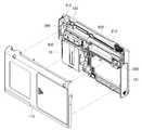
도 1은 본 발명의 일 실시예에 따른 일체형 혈당 측정기의 외형을 개략적으로 도시한 사시도,
도 2는 본 발명의 일 실시예에 따른 일체형 혈당 측정기의 내부 조립 구조를 개략적으로 도시한 사시도,
도 3은 본 발명의 일 실시예에 따른 일체형 혈당 측정기의 구성을 개략적으로 도시한 분해 사시도,
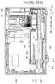
도 4는 본 발명의 일 실시예에 따른 일체형 혈당 측정기의 내부 구조를 개략적으로 도시한 단면도,
도 5는 본 발명의 일 실시예에 따른 일체형 혈당 측정기의 스트립 로딩 유닛과 카트리지 개폐 모듈의 결합 구조를 개략적으로 도시한 분해 사시도,
도 6은 본 발명의 일 실시예에 따른 일체형 혈당 측정기의 스트립 로딩 유닛과 카트리지 개폐 모듈의 작동 상태를 개략적으로 도시한 작동 상태도,
도 7은 본 발명의 일 실시예에 따른 일체형 혈당 측정기의 이동 제한 가이드부에 대한 구성을 개략적으로 도시한 도면,
도 8은 본 발명의 일 실시예에 따른 일체형 혈당 측정기의 로딩 작동 잠금 장치의 구성 및 작동 상태를 개략적으로 도시한 도면,
도 9는 본 발명의 일 실시예에 따른 일체형 혈당 측정기의 스트립 로딩 유닛에 대한 최초 작동 상태를 개략적으로 도시한 도면,
도 10은 본 발명의 일 실시예에 따른 일체형 혈당 측정기의 스트립 로딩 유닛에 대한 최종 작동 완료 상태를 개략적으로 도시한 도면,
도 11은 본 발명의 일 실시예에 따른 일체형 혈당 측정기의 이젝팅 유닛에 대한 구성을 개략적으로 도시한 사시도,
도 12는 본 발명의 일 실시예에 따른 일체형 혈당 측정기의 이젝팅 유닛에 대한 세부 구성을 개략적으로 도시한 분해 사시도,
도 13은 본 발명의 일 실시예에 따른 일체형 혈당 측정기의 이젝팅 유닛에 대한 내부 구조 및 작동 상태를 개략적으로 도시한 단면도이다.1 is a perspective view schematically showing the appearance of an integrated blood glucose meter according to an embodiment of the present invention;
Figure 2 is a perspective view schematically showing the internal assembly structure of the integrated blood glucose meter according to an embodiment of the present invention,
3 is an exploded perspective view schematically showing the configuration of an integrated blood glucose meter according to an embodiment of the present invention;
Figure 4 is a cross-sectional view schematically showing the internal structure of the integrated blood glucose meter according to an embodiment of the present invention,
5 is an exploded perspective view schematically illustrating a coupling structure of a strip loading unit and a cartridge opening and closing module of an integrated blood glucose meter according to an embodiment of the present invention;
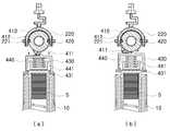
6 is an operating state diagram schematically showing an operating state of the strip loading unit and the cartridge opening and closing module of the integrated blood glucose meter according to one embodiment of the present invention;
7 is a view schematically showing the configuration of the movement limiting guide unit of the integrated blood glucose meter according to an embodiment of the present invention;
8 is a view schematically showing the configuration and operating state of the loading operation locking device of the integrated blood glucose meter according to an embodiment of the present invention;
9 is a schematic illustration of an initial operating state of a strip loading unit of an integrated blood glucose meter according to an embodiment of the present invention;
10 is a view schematically showing a final operation completion state of the strip loading unit of the integrated blood glucose meter according to an embodiment of the present invention;
11 is a perspective view schematically showing the configuration of the ejecting unit of the integrated blood glucose meter according to an embodiment of the present invention;
12 is an exploded perspective view schematically showing a detailed configuration of the ejecting unit of the integrated blood glucose meter according to an embodiment of the present invention;
FIG. 13 is a cross-sectional view schematically illustrating an internal structure and an operating state of an ejecting unit of an integrated blood glucose meter according to an embodiment of the present invention.
이하, 본 발명의 바람직한 실시예를 첨부된 도면들을 참조하여 상세히 설명한다. 우선 각 도면의 구성요소들에 참조부호를 부가함에 있어서, 동일한 구성요소들에 대해서는 비록 다른 도면상에 표시되더라도 가능한 한 동일한 부호를 가지도록 하고 있음에 유의해야 한다. 또한, 본 발명을 설명함에 있어, 관련된 공지 구성 또는 기능에 대한 구체적인 설명이 본 발명의 요지를 흐릴 수 있다고 판단되는 경우에는 그 상세한 설명은 생략한다.Hereinafter, exemplary embodiments of the present invention will be described in detail with reference to the accompanying drawings. First of all, in adding reference numerals to the components of each drawing, it should be noted that the same reference numerals are used as much as possible even if displayed on different drawings. In addition, in describing the present invention, when it is determined that the detailed description of the related well-known configuration or function may obscure the gist of the present invention, the detailed description thereof will be omitted.
도 1은 본 발명의 일 실시예에 따른 일체형 혈당 측정기의 외형을 개략적으로 도시한 사시도이고, 도 2는 본 발명의 일 실시예에 따른 일체형 혈당 측정기의 내부 조립 구조를 개략적으로 도시한 사시도이고, 도 3은 본 발명의 일 실시예에 따른 일체형 혈당 측정기의 구성을 개략적으로 도시한 분해 사시도이고, 도 4는 본 발명의 일 실시예에 따른 일체형 혈당 측정기의 내부 구조를 개략적으로 도시한 단면도이고, 도 5는 본 발명의 일 실시예에 따른 일체형 혈당 측정기의 스트립 로딩 유닛과 카트리지 개폐 모듈의 결합 구조를 개략적으로 도시한 분해 사시도이고, 도 6은 본 발명의 일 실시예에 따른 일체형 혈당 측정기의 스트립 로딩 유닛과 카트리지 개폐 모듈의 작동 상태를 개략적으로 도시한 작동 상태도이고, 도 7은 본 발명의 일 실시예에 따른 일체형 혈당 측정기의 이동 제한 가이드부에 대한 구성을 개략적으로 도시한 도면이고, 도 8은 본 발명의 일 실시예에 따른 일체형 혈당 측정기의 로딩 작동 잠금 장치의 구성 및 작동 상태를 개략적으로 도시한 도면이다.1 is a perspective view schematically showing the external shape of the integrated blood glucose meter according to an embodiment of the present invention, Figure 2 is a perspective view schematically showing the internal assembly structure of the integrated blood glucose meter according to an embodiment of the present invention, Figure 3 is an exploded perspective view schematically showing the configuration of an integrated blood glucose meter according to an embodiment of the present invention, Figure 4 is a cross-sectional view schematically showing the internal structure of the integrated blood glucose meter according to an embodiment of the present invention, 5 is an exploded perspective view schematically illustrating a coupling structure of a strip loading unit and a cartridge opening and closing module of an integrated blood glucose meter according to an embodiment of the present invention, and FIG. 6 is a strip of the integrated blood glucose meter according to an embodiment of the present invention. 7 is an operation state diagram schematically showing an operation state of the loading unit and the cartridge opening / closing module, and FIG. 7 illustrates an operation state according to an embodiment of the present invention. FIG. 8 is a view schematically showing the configuration of the movement limiting guide of the body type blood glucose meter, and FIG. 8 is a view schematically showing the configuration and operating state of the loading operation locking device of the integrated blood glucose meter according to an embodiment of the present invention. .
본 발명의 일 실시예에 따른 일체형 혈당 측정기는 다수개의 검사 스트립이 수납되는 스트립 카트리지를 내부에 수용하여 하나씩 공급할 수 있는 일체형 혈당 측정기로서, 케이스(100)와, 스트립 로딩 유닛(200)과, 카트리지 개폐 모듈(400)과, 이젝팅 유닛(300)을 포함하여 구성된다.An integrated blood glucose meter according to an embodiment of the present invention is an integrated blood glucose meter capable of accommodating and supplying a strip cartridge containing a plurality of test strips therein, the
케이스(100)는 전체 장치의 외곽을 이루는 구성으로, 내부에 수용 공간이 형성되도록 케이스 본체(110)와 케이스 커버(120)로 분리 형성될 수 있으며, 그 사이에는 별도의 중간 지지판(140)이 장착되어 다수의 부품을 장착할 수 있다. 케이스(100)는 내부 공간에 스트립 카트리지(10)를 교체 가능하게 삽입할 수 있도록 형성되며, 이를 위해 내부 공간을 개폐할 수 있도록 별도의 카트리지 도어(160)가 장착될 수 있다. 또한, 케이스(100)의 전면에는 사용자가 조작 가능하도록 버튼 형태의 조작부(102)가 형성되고, 혈당 측정 결과 및 다양한 정보들을 출력하여 디스플레이할 수 있도록 디스플레이부(103)가 형성된다.The
또한, 케이스(100)의 일측단에는 스트립 카트리지(10)로부터 검사 스트립(S)이 일부 구간 배출되어 혈당 측정 모드 상태로 로딩되도록 스트립 배출구(101)가 형성된다. 또한, 스트립 배출구(101)와 인접한 부위에는 스트립 배출구(101)에 로딩된 검사 스트립(S)의 스트립 전극(S1)과 전기적으로 접촉할 수 있도록 커넥터 단자(151)가 장착된 커넥터 하우징(150)이 장착된다. 검사 스트립(S)이 스트립 배출구(101)에 로딩된 상태에서 검사 스트립(S)의 스트립 전극(S1)은 커넥터 하우징(150)의 커넥터 단자(151)에 접촉하여 전기적으로 연결되고, 이 상태에서 검사 스트립(S)에 혈액 샘플을 흡착시켜 혈당 측정 작업을 수행한다. 혈당 측정 작업이 완료된 이후, 사용 완료된 검사 스트립(S)은 케이스(100)로부터 완전하게 외부로 배출 제거한다. 이러한 검사 스트립(S) 배출 제거 과정을 수행할 수 있도록 별도의 이젝팅 유닛(300)이 구비될 수 있다.In addition, a
한편, 도시되지는 않았으나, 케이스(100)의 일측에는 별도의 란셋 장치(미도시)를 탈착 가능하게 결합할 수 있도록 란셋 결합부(130)가 형성되며, 란셋 결합부(130)는 란셋 장치를 슬라이드 결합하도록 형성될 수 있으며, 란셋 장치를 결합하지 않은 경우 별도의 마감 플레이트(131)를 란셋 결합부(130)에 결합하도록 구성될 수 있다. 란셋 장치는 내부 란셋이 구비되어 사용자의 필요에 따라 란셋을 이용하여 혈액을 채취하도록 하는 다양한 방식으로 구성될 수 있다.On the other hand, although not shown, on one side of the
스트립 카트리지(10)는 내부에 다수개의 검사 스트립(S)이 상하 적층되는 형태로 배치되며, 상부에는 검사 스트립을 공급할 수 있도록 공급 개구부(11)가 형성되며, 하부에는 탄성 스프링이 장착되어 다수개 적층된 검사 스트립(S)을 탄성력에 의해 상부측으로 밀어내도록 구성된다. 따라서, 공급 개구부(11)를 통해 하나의 검사 스트립(S)을 외부로 배출하면, 이후 하부측에 적층된 또 다른 검사 스트립(S)이 공급 개구부(11) 측으로 상향 이동하며 공급 대기 상태를 이루게 된다.The
또한, 스트립 카트리지(10)에 수납된 검사 스트립(S)은 외부 습도에 의해 변성되기 쉬우므로, 밀봉 상태로 수납되는 것이 바람직하며, 도시되지는 않았으나 공급 개구부(11)에 별도의 밀봉 테이프(미도시) 등이 부착될 수 있으며, 밀봉 테이프를 제거함과 동시에 케이스(100)에 삽입되도록 구성될 수 있다. 아울러, 이러한 스트립 카트리지(10) 내부 공간에 대한 밀봉 상태가 케이스(100) 내부에 삽입된 상태에서도 마찬가지로 유지되는 것이 중요한데, 이는 카트리지 개폐 모듈(400)을 통해 수행될 수 있다.In addition, since the test strip S accommodated in the
이러한 스트립 카트리지(10)는 내부의 검사 스트립(S)을 다 사용한 이후 다시 새로운 스트립 카트리지로 교체 가능하도록 구성되며, 별도의 고정 클립(미도시) 등을 통해 케이스(100)에 탈부착 용이하도록 구성될 수 있다.The
스트립 로딩 유닛(200)은 사용자에 의해 직선 이동 조작 가능하도록 케이스(100)에 장착되며, 스트립 카트리지(10)의 공급 개구부(11)를 통해 공급되는 검사 스트립(S)을 하나씩 스트립 배출구(101)로 일부 구간 배출시켜 혈당 측정 모드 상태로 로딩시키도록 작동한다.The
카트리지 개폐 모듈(400)은 케이스(100) 내부에 장착되며, 스트립 로딩 유닛(200)의 동작에 연동하여 스트립 카트리지(10)의 공급 개구부(11)를 개폐하도록 작동한다.The cartridge opening and
즉, 스트립 로딩 유닛(200)이 로딩 작동되지 않은 기준 상태에서 카트리지 개폐 모듈(400)은 스트립 카트리지(10)의 공급 개구부(11)를 폐쇄하도록 작동하고, 스트립 로딩 유닛(200)이 스트립 카트리지(10)로부터 검사 스트립(S) 로딩을 위해 작동하는 경우, 카트리지 개폐 모듈(400)은 스트립 카트리지(10)의 공급 개구부(11)를 개방하도록 작동한다. 이러한 카트리지 개폐 모듈(400)은 스트립 로딩 유닛(200)의 동작에 연동하여 작동하므로, 스트립 로딩 유닛(200)에 의해 검사 스트립(S)을 로딩시키는 과정에서만 스트립 카트리지(10)의 공급 개구부(11)가 개방되고, 검사 스트립(S)의 로딩 과정이 완료되면, 스트립 로딩 유닛(200)이 기준 위치로 원상 복귀하고 이에 따라 카트리지 개폐 모듈(400)에 의해 스트립 카트리지(10)의 공급 개구부(11)가 폐쇄된다.That is, the cartridge opening and
이젝팅 유닛(300)은 스트립 로딩 유닛(200)에 의해 스트립 배출구(101)에 로딩된 검사 스트립(S)을 스트립 배출구(101)로부터 배출 제거하도록 작동하는 것으로, 사용자에 의해 가압 조작 가능하도록 케이스(100)에 장착된다.The ejecting
이와 같은 구조에 따라 스트립 로딩 유닛(200)을 직선 이동 조작하여 스트립 카트리지(10)로부터 하나씩 검사 스트립(S)을 스트립 배출구(101)에 로딩할 수 있고, 검사 스트립(S)을 로딩한 상태에서 혈당 측정 작업을 진행한 후, 혈당 측정 작업이 완료되면, 이젝팅 유닛(300)을 조작하여 검사 스트립(S)을 스트립 배출구(101)로부터 배출 제거할 수 있다.According to such a structure, the
한편, 본 발명의 일 실시예에 따른 일체형 혈당 측정기는, 케이스(100)의 내부에 배치되어 스트립 로딩 유닛(200)의 작동 여부를 감지하는 로딩 감지 센서(600)와, 로딩 감지 센서(600)의 감지 신호를 인가받아 스트립 카트리지(10)에 남아있는 검사 스트립(S)의 잔존 수량을 연산하여 산출하는 제어부(800)를 더 포함하여 구성될 수 있다.On the other hand, the integrated blood glucose meter according to an embodiment of the present invention, the
이러한 구성에 따라 스트립 로딩 유닛(200)의 작동시마다 로딩 감지 센서(600)가 이를 감지하고, 로딩 감지 센서(600)의 감지 신호가 제어부(800)에 인가되어 감지 신호의 인가 횟수를 연산하여 스트립 카트리지(10)에 남아있는 검사 스트립(S)의 잔존 수량을 산출할 수 있다.According to this configuration, the
예를 들어, 50개의 검사 스트립(S)이 내장된 스트립 카트리지(10)를 케이스(100)에 삽입한 경우, 스트립 로딩 유닛(200)이 1회 작동할 때마다 1개의 검사 스트립(S)이 사용된 것이므로, 로딩 감지 센서(600)에 의한 감지 신호의 인가 횟수를 누적 계산하여 스트립 카트리지(10)에 남아있는 검사 스트립(S)의 잔존 수량을 산출한다.For example, when a
이때, 스트립 카트리지(10)에는 검사 스트립(S)의 수량에 대한 정보를 저장하는 카트리지 정보칩(13)이 장착될 수 있고, 제어부(800)에 의해 산출된 검사 스트립(S)의 잔존 수량 정보는 카트리지 정보칩(13)에 송신 저장되도록 구성될 수 있다.At this time, the
이를 위해 케이스(100)에는 스트립 카트리지(10)가 삽입된 상태에서 카트리지 정보칩(13)의 접촉 단자(14)와 접촉할 수 있는 정보 접속 단자(700)가 형성되어 제어부(800)와 연결되며, 카트리지 정보칩(13)의 접촉 단자(14)와 케이스(100)의 정보 접속 단자(700)의 상호 접촉 구조를 통해 검사 스트립(S)의 잔존 수량 정보가 송수신되도록 할 수 있다. 물론, 이러한 정보 송수신 구조는 물리적인 접촉을 통한 정보 송수신 방식이 아니라 무선 정보 송수신 방식 또한 가능하다.To this end, the
이 경우, 제어부(800)는 카트리지 정보칩(13)에 저장된 검사 스트립(S)의 잔존 수량 정보를 수신하고, 로딩 감지 센서(600)의 감지 신호에 따라 검사 스트립(S)의 잔존 수량 정보를 새롭게 산출하고, 새롭게 산출된 검사 스트립(S)의 잔존 수량 정보를 카트리지 정보칩(13)에 다시 송신 저장할 수 있다.In this case, the
또한, 제어부(800)는 산출된 검사 스트립(S)의 잔존 수량 정보를 케이스(100)에 형성된 디스플레이부(103)에 출력하도록 동작 제어할 수 있다.In addition, the
이와 같은 구성에 따라 스트립 카트리지(10)는 카트리지 정보칩(13)을 통해 검사 스트립(S)의 잔존 수량 정보를 항상 새롭게 저장할 수 있고, 따라서, 스트립 카트리지(10)의 검사 스트립(S)을 모두 소진하기 전에 스트립 카트리지(10)를 케이스(100)로부터 분리한 후 다시 스트립 카트리지(10)를 삽입한 경우에도 현재 삽입된 스트립 카트리지(10)에 남아있는 검사 스트립(S)의 잔존 수량을 정확하게 파악할 수 있다.According to such a configuration, the
예를 들면, 최초 제작 유통된 스트립 카트리지(10)는 50개의 검사 스트립(S)이 내장된 상태로 유통되고, 50개의 수량 정보가 카트리지 정보칩(13)에 저장된 상태로 사용 시작될 수 있다. 이러한 스트립 카트리지(10)를 케이스(100)에 삽입하면, 카트리지 정보칩(13)의 접촉 단자(14)와 케이스(100)의 정보 접속 단자(700)를 통해 스트립 카트리지(10)의 검사 스트립(S) 잔존 수량 정보가 제어부(800)로 전달된다. 제어부(800)는 50개의 잔존 수량 정보를 수신한 상태에서 로딩 감지 센서(600)의 감지 신호가 인가될 때마다 잔존 수량을 1개씩 차감하는 방식으로 검사 스트립(S)의 잔존 수량을 연산 산출하고, 해당 잔존 수량 정보를 디스플레이부(103)에 출력하여 사용자에게 이를 인식하도록 할 수 있다.For example, the
이때, 사용자가 검사 스트립(S)의 잔존 수량이 20개가 남아있는 상태에서 스트립 카트리지(10)를 특별한 사정에 의해 분리 제거한 후, 이를 다시 삽입하거나 또는 다른 일체형 혈당 측정기에 삽입하여 사용할 수 있다.At this time, the user can remove and remove the
이와 같이 스트립 카트리지(10)가 케이스(100)에 삽입되면, 제어부(800)는 스트립 카트리지(10)의 카트리지 정보칩(13)에 저장된 검사 스트립(S)의 잔존 수량 정보를 수신하게 되므로, 상기 예에서는 잔존 수량 20개의 정보를 수신하게 된다. 이 상태에서 스트립 로딩 유닛(200)을 작동하여 계속적으로 사용하게 되면, 20개의 잔존 수량 정보로부터 로딩 감지 센서(600)의 감지 신호 인가 횟수마다 1개씩 차감하여 새롭게 잔존 수량 정보를 산출할 수 있다.As such, when the
이는 스트립 카트리지(10)의 검사 스트립(S)을 완전히 소진하지 않고 중간에 스트립 카트리지(10)를 분리한 이후 다시 삽입하여 사용하는 경우 검사 스트립(S)의 잔존 수량을 초기 상태로 인식하는 오류를 방지하기 위함으로, 본 발명의 일 실시예에서는 제어부(800)를 통해 산출된 검사 스트립(S)의 잔존 수량 정보를 카트리지 정보칩(13)에 송신 저장하게 되므로, 중간에 스트립 카트리지(10)를 분리한 후 이를 다시 사용하는 경우에도 항상 정확하게 검사 스트립(S)의 잔존 수량 정보를 파악할 수 있다.This is an error of recognizing the remaining quantity of the test strip (S) as an initial state when the test strip (S) of the strip cartridge (10) is not completely exhausted and when the strip cartridge (10) is removed and inserted again in the middle. In order to prevent this, in one embodiment of the present invention, since the remaining quantity information of the test strip S calculated by the
이와 같이 검사 스트립(S)에 대한 잔존 수량 정보를 항상 정확하게 산출하여 디스플레이부(103)에 출력함으로써, 사용자에게 스트립 카트리지(10)의 교체 시기를 미리 알려주어 대비할 수 있도록 하며, 이에 따라 더욱 안정적으로 사용하게 할 수 있다.As such, the remaining quantity information of the test strip S is always accurately calculated and output to the
한편, 케이스(100)의 스트립 배출구(101)에는 커넥터 단자(151)가 형성된 커넥터 하우징(150)이 장착되며, 검사 스트립(S)이 정상적으로 로딩된 경우, 검사 스트립(S)의 스트립 전극(S1)이 커넥터 단자(151)에 접촉하게 된다. 스트립 전극(S1)과 커넥터 단자(151)의 접촉에 따라 발생하는 검사 스트립(S)의 로딩 신호는 커넥터 단자(151)를 통해 제어부(800)로 인가된다.On the other hand, the
이때, 제어부(800)는 커넥터 단자(151)를 통해 검사 스트립(S)의 로딩 신호를 인가받은 경우, 로딩 감지 센서(600)의 감지 신호 인가 여부에 따라 디스플레이부(103)에 알림 메시지가 출력되도록 동작 제어한다.In this case, when the
예를 들면, 제어부(800)에 커넥터 단자(151)의 검사 스트립(S) 로딩 신호가 인가되고 로딩 감지 센서(600)의 감지 신호가 인가되지 않은 경우, 이는 스트립 로딩 유닛(200)이 작동하지 않은 상태에서 별도의 검사 스트립(S)이 외부에서 삽입되어 로딩된 것이므로, 제어부(800)는 디스플레이부(103)에 에러 메시지가 출력되도록 동작 제어할 수 있다. 에러 메시지는 예를 들면, "재시도 해주십시요" 또는 "정상적인 검사 스트립이 아닙니다." 등과 같이 정상적으로 검사 스트립(S)을 스트립 로딩 유닛(200)에 의해 로딩하도록 유도하는 방식으로 형성될 수 있다.For example, when the test strip S loading signal of the
또한, 제어부(800)에 로딩 감지 센서(600)의 감지 신호가 인가되고 커넥터 단자(151)의 검사 스트립(S) 로딩 신호가 인가되지 않은 경우, 이는 스트립 로딩 유닛(200)이 작동했는데도 불구하고 검사 스트립(S)이 로딩되지 않은 것으로 스트립 카트리지(10)에 검사 스트립(S)이 남아있지 않은 경우이므로, 제어부(800)는 디스플레이부(103)에 검사 스트립(S)의 잔존 수량이 없음 또는 스트립 카트리지(10)의 교체 등을 표시하는 메시지가 출력되도록 동작 제어할 수 있다. 예를 들면, "검사 스트립 없음" 또는 "카트리지 교체" 등의 메시지가 출력되도록 할 수 있다.In addition, when the detection signal of the
이와 같은 구성에 따라 커넥터 단자(151)를 통한 검사 스트립(S)의 로딩 신호와 로딩 감지 센서(600)의 감지 신호를 상호 비교하여 검사 스트립(S)의 정상적인 로딩 상태를 정확하게 판단할 수 있어 검사 스트립(S)에 대한 잔존 수량의 관리를 더욱 정확하게 수행할 수 있다.According to such a configuration, the normal loading state of the test strip S can be accurately determined by comparing the loading signal of the test strip S through the
다음으로, 본 발명의 일 실시예에 따른 일체형 혈당 측정기의 세부 구성에 대해 좀더 자세히 살펴본다.Next, the detailed configuration of the integrated blood glucose meter according to an embodiment of the present invention will be described in more detail.
스트립 로딩 유닛(200)은, 사용자에 의해 조작 가능하도록 케이스(100)의 일면에 노출되어 직선 이동 가능하게 결합되는 조작 노브(210)와, 조작 노브(210)와 결합되어 일체로 직선 이동하는 이동 바디(220)와, 조작 노브(210)와 일체로 직선 이동하여 스트립 카트리지(10)의 공급 개구부(11)를 통해 공급되는 검사 스트립(S)을 스트립 배출구(101)로 밀어내어 로딩시키는 로딩 플레이트(230)를 포함하여 구성된다. 또한, 스트립 로딩 유닛(200)은 별도의 탄성 스프링(240)에 의해 최초 기준 상태로 복귀하도록 구성된다. 따라서, 사용자가 스트립 로딩 유닛(200)을 직선 이동시킨 상태에서 조작력을 제거하면, 스트립 로딩 유닛(200)은 탄성 스프링(240)의 탄성력에 의해 최초 기준 상태로 자동 복귀한다.The
이때, 스트립 로딩 유닛(200)의 작동 여부를 감지하는 로딩 감지 센서(600)는 이동 바디(220)의 직선 이동 과정에서 이동 바디(220)에 의해 가압되어 작동하는 리미트 스위치 형태로 형성될 수 있으며, 로딩 감지 센서(600)의 장착 위치는 스트립 로딩 유닛(200)의 로딩 직선 이동이 완료된 지점과 인접한 지점까지 이동 바디(220)가 이동한 상태에서 작동하도록 형성될 수 있다.In this case, the
카트리지 개폐 모듈(400)은, 스트립 로딩 유닛(200)의 직선 이동에 연동하여 회전 이동하는 회전 슬리브(410)와, 회전 슬리브(410)의 회전 이동에 따라 가압 또는 가압 해제되어 스트립 카트리지(10)의 공급 개구부(11)를 개폐하는 개폐 커버(430)를 포함하여 구성된다. 이때, 회전 슬리브(410)의 외주면 일측에는 개폐 커버(430)를 가압할 수 있도록 가압 돌기(411)가 돌출 형성되고, 개폐 커버(430)는 스트립 카트리지(10)의 공급 개구부(11)를 개폐하도록 상하 직선 이동 가능하게 장착되며, 회전 슬리브(410)에 접촉하는 방향으로 별도의 탄성 스프링(440)에 의해 상향 탄성 지지된다.The cartridge opening and
개폐 커버(430)는 하단면이 개방된 용기 형태로 형성될 수 있으며, 개폐 커버(430)의 하단 가장자리에는 스트립 카트리지(10)의 공급 개구부(11)를 밀봉되게 폐쇄할 수 있도록 실링 부재(431)가 장착될 수 있으며, 탄성 스프링(440)은 별도의 지지판(441)에 의해 지지되어 개폐 커버(430)를 탄성 지지하도록 구성되며, 이러한 개폐 커버(430)의 외곽에는 개폐 커버(430)의 상하 직선 이동 경로를 가이드하는 별도의 베이스 하우징(450)이 배치될 수 있다.The opening and
또한, 회전 슬리브(410)의 내부 공간에는 중심축 방향을 따라 별도의 지지 샤프트(420)가 삽입 결합될 수 있으며, 회전 슬리브(410)는 지지 샤프트(420)의 외주면에 결합되어 회전 이동하도록 구성될 수 있다.In addition, a
이때, 회전 슬리브(410)가 스트립 로딩 유닛(200)의 직선 이동에 연동하여 회전 이동하는 구조는 스트립 로딩 유닛(200)의 이동 바디(220)와 회전 슬리브(410)가 서로 맞물림되는 캠 구조를 갖는 구조를 통해 달성될 수 있다. 예를 들면, 도 5에 도시된 바와 같이 회전 슬리브(410)의 외주면에는 최초 구간에서 곡선 경로를 갖는 캠홈(412)이 형성되고, 이동 바디(220)의 내측면 일측에는 캠홈(412)에 맞물림되는 캠돌기(221)가 형성될 수 있다.At this time, the structure in which the
이러한 구조에 따라 스트립 로딩 유닛(200)의 이동 바디(220)가 직선 이동하면, 캠돌기(221)와 캠홈(412)이 맞물림된 상태로 상호 이동하며, 캠돌기(221)와 캠홈(412)의 맞물림 구조에 따라 회전 슬리브(410)가 지지 샤프트(420)를 회전축으로 하여 회전 이동하게 된다. 이때, 이동 바디(220)가 직선 이동하며 캠돌기(221)가 캠홈(412)의 최초 곡선 경로 구간에 맞물림되어 이동하는 과정에서 회전 슬리브(410)가 회전하고, 그 이후 직선 이동 구간에서는 캠홈(421)이 직선 경로로 형성되므로, 회전 슬리브(410)는 최초 회전 상태를 그대로 유지된다.According to this structure, when the moving
회전 슬리브(410)의 가압 돌기(411)는 도 6의 (a)에 도시된 바와 같이 스트립 로딩 유닛(200)이 작동하지 않은 기준 상태에서 개폐 커버(430)를 가압하도록 형성되고, 스트립 로딩 유닛(200)이 작동하여 회전 슬리브(410)가 회전 이동하면, 도 6의 (b)에 도시된 바와 같이 회전 슬리브(410)의 외주면에 형성된 가압 돌기(411) 또한 회전하게 되고, 이에 따라 가압 돌기(411)의 개폐 커버(430)에 대한 가압 상태가 해제되어 개폐 커버(430)가 탄성 스프링(440)의 탄성력에 의해 상향 이동하며 스트립 카트리지(10)의 공급 개구부(11)를 개방하게 된다. 이와 동시에 스트립 로딩 유닛(200)의 로딩 플레이트(230)가 직선 이동하며 스트립 카트리지(10)의 공급 개구부(11)에 노출된 검사 스트립(S)을 밀어내며 스트립 배출구(101)로 배출시키게 된다. 이때, 로딩 플레이트(230)는 검사 스트립(S)을 밀어내는 과정에서 스트립 카트리지(10)의 공급 개구부(11)를 폐쇄하도록 구성된다.The
이와 같은 구조에 따라 카트리지 개폐 모듈(400)은 개폐 커버(430)가 회전 슬리브(410)의 가압 돌기(411)에 의해 가압되어 스트립 카트리지(10)의 공급 개구부(11)를 항상 밀봉되게 폐쇄하도록 유지되며, 사용자가 스트립 로딩 유닛(200)을 직선 이동 조작하는 경우에만, 회전 슬리브(410)의 가압 돌기(411)에 의한 가압 상태가 해제되어 개폐 커버(430)가 개방된다. 스트립 로딩 유닛(200)의 직선 이동이 완료된 이후 스트립 로딩 유닛(200)은 탄성 스프링(240)에 의해 기준 상태로 복귀하게 되는데, 이때 다시 회전 슬리브(410)가 원상 복귀 상태로 회전하여 가압 돌기(411)에 의해 개폐 커버(430)가 가압되므로, 스트립 카트리지(10)의 공급 개구부(11)가 다시 밀봉 폐쇄된다. 특히, 스트립 로딩 유닛(200)이 직선 이동한 상태에서도 로딩 플레이트(230)에 의해 공급 개구부(11)가 임시 폐쇄되므로, 스트립 카트리지(10)의 내부 공간에 대한 밀봉 상태를 더욱 안정적으로 유지시킬 수 있다.According to this structure, the cartridge opening and
한편, 케이스(100)에는 스트립 로딩 유닛(200)이 검사 스트립(S)을 로딩하는 직선 이동 과정을 완료하기 이전에 기준 위치로 원상 복귀하는 것을 방지하도록 스트립 로딩 유닛(200)을 가이드하는 이동 제한 가이드부(180)가 형성된다.On the other hand, the
스트립 로딩 유닛(200)의 이동 바디(220)의 일측에는 도 7에 도시된 바와 같이 별도의 가이드 돌기(250)가 돌출 형성되는데, 가이드 돌기(250)는 이동 바디(220)에 회동 가능하게 결합되는 가이드 블록(251)에 결합되어 일정 구간 회전 이동 가능하게 구성될 수 있으며, 이동 제한 가이드부(180)는 이러한 가이드 돌기(250)와 맞물림되는 방식으로 스트립 로딩 유닛(200)의 이동 경로를 가이드함과 동시에 원상 복귀를 구속한다.One side of the moving
이러한 이동 제한 가이드부(180)는 도 7에 도시된 바와 같이 스트립 로딩 유닛(200)의 검사 스트립(S) 로딩을 위한 직선 이동 경로를 가이드하는 이동 경로 가이드 레일(181)과, 스트립 로딩 유닛(200)의 원상 복귀 이동 경로를 가이드하는 복귀 경로 가이드 레일(182)을 포함하여 구성된다. 이때, 이동 경로 가이드 레일(181)에는 스트립 로딩 유닛(200)의 원상 복귀를 방지하도록 중간 구간에 다수개의 래칫 돌기(183)가 형성된다. 스트립 로딩 유닛(200)는 이동 바디(220)에 형성된 가이드 돌기(250)가 이동 경로 가이드 레일(181)과 복귀 경로 가이드 레일(182)에 삽입 가이드되어 이동하도록 구성된다.As shown in FIG. 7, the movement
따라서, 스트립 로딩 유닛(200)은 도 7의 (a)에 도시된 바와 같이 검사 스트립(S) 로딩을 위한 직선 이동 구간에서 가이드 돌기(250)가 이동 경로 가이드 레일(181)을 따라 이동하게 되고, 검사 스트립(S) 로딩 직선 이동이 완료된 이후, 도 7의 (b)에 도시된 바와 같이 복귀 경로 가이드 레일(182)을 따라 원상 복귀하게 된다. 이때, 이동 경로 가이드 레일(181) 상에는 래칫 돌기(183)가 형성되므로, 검사 스트립(S) 로딩 직선 이동시에는 가이드 돌기(250)와 맞물림 없이 원활하게 직선 이동하지만, 이 구간에서, 즉, 직선 이동 과정 중간에 기준 위치로 원상 복귀하고자 하는 경우에는 가이드 돌기(250)가 래칫 돌기(183)와 맞물림되어 원상 복귀가 불가능하다. 따라서, 조작 노브(210)를 로딩 직선 이동시키기 시작하면, 로딩 직선 이동까지 모두 완료한 이후에만, 원상 복귀할 수 있다.Therefore, the
즉, 사용자가 조작 노브(210)를 로딩 직선 이동시키는 과정에서 실수 또는 고의로 조작 노브(210)를 조작 해제하더라도 조작 노브(210) 및 이를 포함하는 스트립 로딩 유닛(200)이 기준 위치로 원상 복귀하지 않고 이동 제한 가이드부(180)에 의해 그 위치에 그대로 위치 고정된다.That is, even if the user accidentally or intentionally releases the
이러한 구조를 통해 검사 스트립(S)을 배출시키는 중간 단계에서 배출 과정을 중단하지 못하도록 함으로써, 검사 스트립(S)의 규칙적인 배출을 가능하게 함과 동시에 검사 스트립(S)의 손상 등을 방지할 수 있으며, 스트립 카트리지(10)의 검사 스트립(S) 잔존 수량에 대한 관리 등 다양한 부가 기능을 창출할 수 있다.This structure prevents the discharging process in the intermediate stage of discharging the test strip S, thereby enabling regular discharge of the test strip S and at the same time preventing damage to the test strip S. In addition, various additional functions such as management of the remaining quantity of the test strip S of the
또한, 케이스(100)에는 스트립 카트리지(10)가 삽입되지 않은 상태에서 스트립 로딩 유닛(200)의 작동을 차단하도록 로딩 작동 잠금 장치(500)가 장착될 수 있다.In addition, the
로딩 작동 잠금 장치(500)는, 케이스(100) 내부에 직선 이동 가능하게 장착되며 스트립 카트리지(10)가 삽입됨에 따라 스트립 카트리지(10)에 맞물림되어 스트립 카트리지(10) 삽입 방향으로 직선 이동하는 잠금 블록(510)과, 잠금 블록(510)이 스트립 카트리지(10) 삽입 방향의 반대 방향으로 탄성 이동하도록 잠금 블록(510에 탄성력을 가하는 탄성 부재(520)를 포함할 수 있고, 잠금 블록(510)의 직선 이동에 따라 스트립 로딩 유닛(200)의 작동을 차단 또는 차단 해제하도록 구성될 수 있다. 이때, 탄성 부재(520)는 탄성력이 있는 고무 등의 재질로 지그재그 형상을 통해 탄성력을 발휘할 수 있는 형태로 형성될 수 있으나, 이와 달리 일반 탄성 스프링 등 다양한 형태로 형성될 수 있다.The loading
또한, 케이스(100)에는 잠금 블록(510) 및 탄성 부재(520)의 작동 경로를 가이드하도록 잠금 가이드부(170)가 형성될 수 있으며, 스트립 카트리지(10)에는 잠금 블록(510)과 맞물림될 수 있도록 단턱홈(12)이 형성될 수 있다. 또한, 잠금 블록(510)에는 스트립 카트리지(10)의 단턱홈(12)과 맞물림되도록 걸림 돌기(512)가 형성될 수 있고, 중심 영역에는 스트립 로딩 유닛(200)의 로딩 플레이트(230)가 통과할 수 있도록 이동홀(511)이 형성될 수 있다.In addition, the
이러한 구조에 따라 스트립 카트리지(10)를 케이스(100)에 삽입하게 되면, 도 8의 (a)에 도시된 바와 같이 스트립 카트리지(10)의 단턱홈(12)에 잠금 블록(510)의 걸림 돌기(512)가 맞물림되어 스트립 카트리지(10)의 삽입 방향을 따라 잠금 블록(510)이 상향 이동하게 된다. 이때, 탄성 부재(520)는 탄성 압착된다. 이와 같이 잠금 블록(510)이 상향 이동함에 따라 잠금 블록(510)에 형성된 이동홀(511)의 위치가 상향 이동하고, 이 상태에서 이동홀(511)의 위치는 스트립 로딩 유닛(200)의 로딩 플레이트(230)가 로딩 직선 이동하는 경로 상에 위치하게 된다. 따라서, 이 상태에서 스트립 로딩 유닛(200)을 이동 조작하게 되면, 로딩 플레이트(230)가 이동홀(511)을 통해 직선 이동할 수 있으므로 스트립 로딩 유닛(200)의 작동이 원활하게 이루어진다.When the
반면, 스트립 카트리지(10)를 케이스(100)로부터 분리 제거하면, 도 8의 (b)에 도시된 바와 같이 스트립 카트리지(10)의 단턱홈(12)과 잠금 블록(510)의 걸림 돌기(512)와의 맞물림 상태가 해제되므로, 잠금 블록(510)은 탄성 부재(520)의 탄성력에 의해 하향 이동하게 된다. 이때, 잠금 블록(510)의 이동홀(511)의 위치 또한 하향 이동하게 되므로, 이 상태에서는 로딩 플레이트(230)의 직선 이동이 잠금 블록(510)에 의해 차단된다. 즉, 스트립 카트리지(10)를 케이스(100)로부터 분리 제거하면, 잠금 블록(510)에 의해 로딩 플레이트(230)의 직선 이동이 차단되므로, 스트립 로딩 유닛(200)의 작동이 이루어지지 않게 된다.On the other hand, if the
이와 같은 구조에 따라 본 발명의 일 실시예에 따른 일체형 혈당 측정기는 로딩 작동 잠금 장치(500)를 통해 스트립 카트리지(10)가 삽입되지 않은 상태에서는 조작 노브(210)의 조작이 이루어지지 않도록 할 수 있고, 이에 따라 조작 노브(210) 및 스트립 로딩 유닛(200)의 불필요하고 과도한 이동 조작을 방지하여 손상을 방지할 수 있고, 안정성을 유지할 수 있다.According to such a structure, the integrated blood glucose meter according to the embodiment of the present invention may prevent the
이상에서 설명한 구조에 따라 본 발명의 일 실시예에 따른 일체형 혈당 측정기의 동작 상태를 도 9 및 도 10을 중심으로 살펴본다.According to the structure described above, the operating state of the integrated blood glucose meter according to an embodiment of the present invention will be described with reference to FIGS. 9 and 10.
도 9는 본 발명의 일 실시예에 따른 일체형 혈당 측정기의 스트립 로딩 유닛에 대한 최초 작동 상태를 개략적으로 도시한 도면이고, 도 10은 본 발명의 일 실시예에 따른 일체형 혈당 측정기의 스트립 로딩 유닛에 대한 최종 작동 완료 상태를 개략적으로 도시한 도면이다.9 is a view schematically showing the initial operating state of the strip loading unit of the integrated blood glucose meter according to an embodiment of the present invention, Figure 10 is a strip loading unit of the integrated blood glucose meter according to an embodiment of the present invention It is a diagram schematically showing the final operation completion state for.
도 4에는 스트립 로딩 유닛(200)이 기준 위치에 위치한 상태가 도시되며, 도 9에는 스트립 로딩 유닛(200)의 최초 이동 시작 상태가 도시된다. 도 9에 도시된 바와 같이 조작 노브(210)를 도시된 방향을 기준으로 좌측으로 로딩 직선 이동을 시작하면, 이와 함께 이동 바디(220)가 이동하고, 이동 바디(220)와 캠 구조로 연결된 회전 슬리브(410)가 회전하며, 이와 함께 회전 슬리브(410)의 가압 돌기(411)가 회전하여 가압 돌기(411)의 개폐 커버(430)에 대한 가압 상태가 해제되어 개폐 커버(430)는 탄성 스프링(440)의 탄성력에 의해 상향 이동하며 스트립 카트리지(10)의 공급 개구부(11)를 개방하게 된다. 이때, 로딩 플레이트(230)는 공급 개구부(11)에 인접하게 위치하게 된다.4 shows a state in which the
이후, 조작 노브(210)를 계속해서 좌측 방향으로 직선 이동시키면, 도 10에 도시된 바와 같이 로딩 직선 이동 구간의 완료 지점까지 직선 이동하게 된다. 이 과정에서 로딩 플레이트(230)가 이동하여 스트립 카트리지(10)의 공급 개구부(11)로부터 검사 스트립(S)을 스트립 배출구(101)로 밀어낸다. 이때, 검사 스트립(S)은 일부 구간이 스트립 배출구(101)로 배출되어 로딩되며, 스트립 배출구(101) 주변에 장착된 커넥터 하우징(150)의 커넥터 단자(151)에 접촉된 상태로 유지된다. 이 상태에서 사용자는 일부 배출된 상태로 로딩된 검사 스트립(S)에 혈액 샘플을 흡착시켜 혈당 측정 작업을 수행할 수 있다.Subsequently, if the
이와 같이 검사 스트립(S)을 로딩한 상태에서 로딩 플레이트(230)가 스트립 카트리지(10)의 공급 개구부(11)를 폐쇄하므로, 이 상태에서도 스트립 카트리지(10)의 내부 공간은 밀폐 상태가 유지된다. 이후, 조작 노브(210)에 대한 조작력을 해제하면, 스트립 로딩 유닛(200)은 탄성 스프링(240)의 탄성력에 의해 기준 위치로 복귀하게 된다. 복귀 과정에서 회전 슬리브(410)가 다시 반대 방향으로 회전하며 가압 돌기(411)를 통해 개폐 커버(430)를 가압하여 스트립 카트리지(10)의 공급 개구부(11)를 폐쇄한다.Since the
이러한 방식으로 스트립 카트리지(10)의 검사 스트립(S)을 스트립 배출구(101)에 로딩시키고, 이 상태에서 검사 스트립(S)에 혈액 샘플을 흡착시켜 혈당 측정 작업을 수행하는데, 혈당 측정 작업이 완료되면, 이젝팅 유닛(300)을 가압 조작하여 스트립 배출구(101)에 로딩된 검사 스트립(S)을 스트립 배출구(101)로부터 완전히 배출시켜 제거할 수 있다.In this way, the test strip S of the
다음으로, 본 발명의 일 실시예에 따른 이젝팅 유닛의 구성에 대해 도 11 내지 도 13을 중심으로 좀더 자세히 살펴본다.Next, the configuration of the ejecting unit according to an embodiment of the present invention will be described in more detail with reference to FIGS. 11 to 13.
도 11은 본 발명의 일 실시예에 따른 일체형 혈당 측정기의 이젝팅 유닛에 대한 구성을 개략적으로 도시한 사시도이고, 도 12는 본 발명의 일 실시예에 따른 일체형 혈당 측정기의 이젝팅 유닛에 대한 세부 구성을 개략적으로 도시한 분해 사시도이고, 도 13은 본 발명의 일 실시예에 따른 일체형 혈당 측정기의 이젝팅 유닛에 대한 내부 구조 및 작동 상태를 개략적으로 도시한 단면도이다.11 is a perspective view schematically illustrating a configuration of an ejecting unit of an integrated blood glucose meter according to an embodiment of the present invention, and FIG. 12 is a detail of an ejecting unit of an integrated blood glucose meter according to an embodiment of the present invention. 13 is an exploded perspective view schematically illustrating a configuration, and FIG. 13 is a cross-sectional view schematically illustrating an internal structure and an operating state of an ejecting unit of an integrated blood glucose meter according to an embodiment of the present invention.
이젝팅 유닛(300)은 케이스(100)의 스트립 배출구(101)에 인접한 위치에 장착되며, 사용자에 의해 가압 조작 가능하도록 형성되어 스트립 배출구(101)에 로딩된 검사 스트립(S)을 스트립 배출구(101)로부터 배출 제거하도록 작동한다.The ejecting
이러한 이젝팅 유닛(300)은 사용자의 가압 조작에 의해 발생한 일방향 이동력을 이에 대한 직각 방향의 이동력으로 전환하도록 형성되며, 전환된 직각 방향의 이동력에 의해 검사 스트립(S)이 배출되도록 구성된다.The ejecting
이와 같은 이젝팅 유닛(300)을 통해 혈당 측정 작업이 완료된 이후 단순한 가압 조작을 통해 편리하고 신속하게 검사 스트립(S)을 스트립 배출구(101)로부터 배출 제거할 수 있다. 특히, 사용자의 가압 조작력을 직각 방향의 이동력으로 전환하는 메카니즘을 통해 검사 스트립(S)을 외부 배출하며, 이때, 별도의 탄성력에 의해 검사 스트립을 배출시키는 것이 아니라 단순히 직각 방향으로 전환된 사용자의 조작력에 의해 검사 스트립을 배출시키는 것이므로, 검사 스트립(S)의 배출시 너무 강하게 튀어 나가지 않고 사용자의 조작력에 대응하여 적절한 속도로 외부 배출된다. 따라서, 배출되는 검사 스트립(S)을 용이하게 쓰레기통 등에 곧바로 투입시킬 수 있고, 검사 스트립(S)을 사용자의 손에 묻히지 않고 편리하게 배출 수거할 수 있다.After the blood glucose measurement operation is completed through the ejecting
이젝팅 유닛(300)의 구성을 좀더 자세히 살펴보면, 이젝팅 유닛(300)은, 사용자에 의해 가압 조작되도록 케이스(100)에 상하 이동 가능하게 결합되며 별도의 탄성 스프링(311)에 의해 상향 탄성 지지되는 가압 버튼(310)과, 가압 버튼(310)의 상하 이동에 연동하여 수평 이동하도록 스트립 배출구(101)의 커넥터 하우징(150)에 수평 이동 가능하게 결합되는 배출 블록 모듈(320)과, 가압 버튼(310)과 배출 블록 모듈(320)을 상호 연동시키는 연동 수단(330)을 포함하며, 가압 버튼(310)에 연동하는 배출 블록 모듈(320)의 수평 이동에 의해 검사 스트립(S)이 배출되도록 구성된다. 이때, 가압 버튼(310)은 별도의 탄성 스프링(311)에 의해 상향 탄성 지지되는데, 케이스(100)에는 이러한 탄성 스프링(311)을 지지하도록 별도의 버튼 지지부(190)가 형성될 수 있다.Looking at the configuration of the ejecting
이때, 연동 수단(330)은 가압 버튼(310)과 함께 일체로 상하 이동하도록 가압 버튼(310)에 결합되며 일측에는 경사 방향의 경사 가이드홈(331-1)이 형성되는 가이드 플레이트(331)와, 배출 블록 모듈(320)에 결합되어 배출 블록 모듈(320)과 일체로 이동하며 끝단부가 가이드 플레이트(331)의 경사 가이드홈(331-1)에 삽입되어 경사 가이드홈(331-1)을 따라 이동하는 가이드 로드(332)를 포함하여 구성된다.At this time, the interlocking means 330 is coupled to the
연동 수단(330)인 가이드 플레이트(331)와 가이드 로드(332)는 각각 가압 버튼(310)과 배출 블록 모듈(320)에 분리 가능한 형태로 결합될 수도 있으나, 이와 달리 각각 가압 버튼(310)과 배출 블록 모듈(320)에 일체로 형성될 수도 있다.The
예를 들면, 가이드 플레이트(331)는 합성 수지 재질로 가압 버튼(310)과 일체로 성형 제작될 수 있으며, 가이드 로드(332)는 금속 재질로 별도로 형성되어 별도의 체결 수단을 통해 배출 블록 모듈(320)에 관통 결합되는 형태로 결합될 수 있다. 이와 같이 가이드 플레이트(331)가 합성 수지 재질, 예를 들면, POM(Poly Oxy Methylene) 재질로 형성되고, 가이드 로드(332)가 금속 재질, 예를 들면, 스테인리스 스틸로 형성되면, 금속과 합성 수지의 마찰력이 상대적으로 낮고 마찰 소음이 작아 작동 성능이 향상된다.For example, the
배출 블록 모듈(320)은, 커넥터 하우징(150)에 수평 이동 가능하게 결합되는 배출 블록(321)과, 배출 블록(321)에 상하 이동 가능하게 결합되며 하단부에는 스트립 배출구(101)에 로딩된 검사 스트립(S)과 맞물림될 수 있도록 걸림부(322-2)가 형성되는 걸림 바디(322)와, 걸림 바디(322)의 걸림부(322-2)가 배출 블록(321)으로부터 하향 돌출되도록 걸림 바디(322)를 하향 탄성 지지하는 탄성 스프링(323)을 포함하여 구성된다. 가이드 로드(332)는 배출 블록 모듈(320)을 관통하여 결합하는데, 걸림 바디(322)에는 이러한 가이드 로드(332)가 관통함과 동시에 걸림 바디(322)의 상하 이동이 가능하도록 중심부에 상하 방향으로 길게 슬롯홀(322-1)이 형성된다.The
또한, 걸림 바디(322)의 걸림부(322-2)는 스트립 배출구(101) 방향을 따라 외부를 향하는 측면은 검사 스트립(S)과 맞물림될 수 있도록 수직면을 갖도록 형성되고, 스트립 배출구(101) 방향을 따라 내부를 향하는 측면은 경사면을 갖도록 형성된다.In addition, the engaging portion 322-2 of the locking
이와 같은 구조의 이젝팅 유닛(300)의 작동 상태를 살펴보면, 먼저, 가압 버튼(310)을 가압 조작이 없는 상태에서는 도 13의 (a)에 도시된 바와 같이 탄성 스프링(311)의 탄성력에 의해 가압 버튼(310)은 케이스(100)에서 상향 이동한 상태로 유지된다. 따라서, 가압 버튼(310)과 일체로 이동하는 가이드 플레이트(331) 또한 상향 이동한 상태이며, 이 상태에서 가이드 플레이트(331)의 경사 가이드홈(331-1)에 삽입된 가이드 로드(332)는 도 13에 도시된 방향을 기준으로 경사 가이드홈(331-1)을 따라 좌측 이동한 상태로 유지된다. 가이드 로드(332)와 함께 배출 블록 모듈(320) 또한 좌측 이동한 상태로 유지된다. 이 경우, 검사 스트립(S)은 스트립 배출구(101)에 일부 배출된 로딩 상태로 유지된다. 검사 스트립(S)에는 혈당 측정 과정에서 전기적 신호를 송수신할 수 있도록 스트립 전극(S1)이 형성되는데, 검사 스트립(S)이 스트립 배출구(101)에 로딩된 상태에서, 검사 스트립(S)의 스트립 전극(S1)이 스트립 배출구(101)의 커넥터 하우징(150)에 형성된 커넥터 단자(151)와 접촉 상태로 유지된다. 커넥터 단자(151)는 케이스(100) 내부에 장착된 별도의 혈당 측정 모듈 및 제어부(미도시)에 전기적으로 연결된다.Looking at the operating state of the ejecting
이 상태에서, 도 13의 (b)에 도시된 바와 같이 가압 버튼(310)을 하향 가압하면, 케이스(100)에서 하향 이동하게 되고, 이와 함께 가이드 플레이트(331) 또한 하향 이동한다. 가이드 플레이트(331)가 하향 이동하면, 가이드 로드(332)는 경사 가이드홈(331-1)을 따라 이동하며, 도 13에 도시된 방향을 기준으로 우측 방향으로 직선 이동한다. 가이드 로드(332)와 함께 배출 블록 모듈(320)이 커넥터 하우징(150) 내에서 우측으로 이동하고, 이에 따라 배출 블록 모듈(320)의 걸림부(322-2)가 검사 스트립(S)을 외부로 배출시킨다.In this state, as shown in FIG. 13B, when the
따라서, 본 발명의 일 실시예에 따른 이젝팅 유닛(300)은 별도의 탄성력에 의해 검사 스트립(S)을 외부로 배출시키는 것이 아니라 사용자의 가압 조작력에 의해서만 검사 스트립(S)을 외부로 배출시키기 때문에, 검사 스트립(S)의 외부 배출 과정에서 검사 스트립(S)이 너무 강하게 튀어나가지 않고 사용자의 조작력에 비례하여 적절한 속도로 배출된다. 따라서, 배출되는 검사 스트립(S)을 배출과 동시에 용이하게 쓰레기통 등에 집어 넣을 수 있어 더욱 편리하게 사용할 수 있다. 또한, 이러한 이젝팅 유닛(300)은 그 구성이 단순하여 제작 및 조립 작업이 용이하여 제작 비용을 절감할 수 있고, 크기 소형화 등을 통해 일체형 혈당 측정기 내부의 공간 효율을 향상시킬 수 있다.Therefore, the ejecting
본 발명의 일 실시예에 따른 이젝팅 유닛(300)은 이와 같이 가압 버튼(310)의 하향 가압 조작을 통해 이와 연동하는 배출 블록 모듈(320)을 수평 이동시켜 검사 스트립(S)을 외부 배출시키는데, 이때, 배출 블록 모듈(320)의 걸림부(322-2)가 스트립 배출구(101)보다 하향 돌출되게 위치하여 걸림부(322-2)의 이동 과정에서 검사 스트립(S)을 외부로 배출시키게 된다.Ejecting
이 경우, 검사 스트립(S)을 스트립 로딩 유닛(200)에 의해 스트립 카트리지(10)로부터 밀어내어 스트립 배출구(101)에 일부 배출시켜 로딩시키는 과정에서 걸림 바디(322)의 걸림부(322-2)에 의해 검사 스트립(S)의 이동이 간섭되어 정상적인 로딩 과정이 이루어지지 않을 수 있다. 이를 방지할 수 있도록 배출 블록 모듈(320)은 전술한 바와 같이 걸림부(322-2)가 형성된 걸림 바디(322)를 배출 블록(321)에 상하 이동 가능하게 결합하고, 걸림부(322-2)의 일측면을 경사면을 갖도록 형성할 수 있다. 이러한 구조에 따라 도 13의 (a)의 확대도에 도시된 바와 같이 검사 스트립(S)을 스트립 배출구(101)에 로딩시키는 과정에서 검사 스트립(S)이 걸림부(322-2)의 경사면에 접촉하게 되므로, 검사 스트립(S)은 정상적으로 직선 이동하여 스트립 배출구(101)에 로딩되고, 이와 동시에 걸림부(322-2) 및 걸림 바디(322)는 검사 스트립(S)의 직선 이동에 따라 걸림부(322-2)의 경사면에 의해 상향 이동하게 된다. 검사 스트립(S)이 정상적으로 로딩 이동 완료하게 되면, 걸림 바디(322) 및 걸림부(322-2)는 탄성 스프링(323)의 탄성력에 의해 다시 하향 이동하여 원 상태로 복귀한다.In this case, the catching portion 322-2 of the catching
또한, 이와 같이 걸림 바디(322)의 걸림부(322-2)가 스트립 배출구(101)의 외부를 향하는 측면이 수직면을 갖도록 형성됨으로써, 걸림부(322-2)의 이동에 따라 안정적으로 검사 스트립(S)을 외부로 밀어내어 배출시킬 수 있고, 이와 동시에 스트립 배출구(101)에 또 다른 검사 스트립(S) 또는 얇은 시트 형태의 다른 이물질이 외부로부터 삽입되는 경우, 이러한 검사 스트립(S) 또는 이물질이 케이스(100)의 내부 공간으로 일정 구간 이상 인입되는 것을 방지할 수 있다. 이와 같이 검사 스트립(S) 또는 이물질이 스트립 배출구(101)의 외부로부터 인입되는 경우, 삽입되는 검사 스트립(S) 또는 이물질과 접촉하는 걸림부(322-2)의 측면이 수직면을 가짐으로써, 그 접촉 구조상 걸림부(322-2) 및 걸림 바디(322)의 상향 이동이 일어나지 않게 되고, 이에 따라 외부로부터 검사 스트립(S) 또는 이물질의 인입을 방지할 수 있다.In addition, as the locking portion 322-2 of the locking
이상의 설명은 본 발명의 기술 사상을 예시적으로 설명한 것에 불과한 것으로서, 본 발명이 속하는 기술 분야에서 통상의 지식을 가진 자라면 본 발명의 본질적인 특성에서 벗어나지 않는 범위에서 다양한 수정 및 변형이 가능할 것이다. 따라서, 본 발명에 개시된 실시예들은 본 발명의 기술 사상을 한정하기 위한 것이 아니라 설명하기 위한 것이고, 이러한 실시예에 의하여 본 발명의 기술 사상의 범위가 한정되는 것은 아니다. 본 발명의 보호 범위는 아래의 청구범위에 의하여 해석되어야 하며, 그와 동등한 범위 내에 있는 모든 기술 사상은 본 발명의 권리범위에 포함되는 것으로 해석되어야 할 것이다.The above description is merely illustrative of the technical idea of the present invention, and those skilled in the art to which the present invention pertains may make various modifications and changes without departing from the essential characteristics of the present invention. Therefore, the embodiments disclosed in the present invention are not intended to limit the technical idea of the present invention but to describe the present invention, and the scope of the technical idea of the present invention is not limited by these embodiments. The protection scope of the present invention should be interpreted by the following claims, and all technical ideas within the equivalent scope should be interpreted as being included in the scope of the present invention.
100: 케이스
101: 스트립 배출구150: 커넥터 하우징
151: 커넥터 단자180: 이동 제한 가이드부
200: 스트립 로딩 유닛
210: 조작 노브220: 이동 바디
230: 로딩 플레이트240: 탄성 스프링
250: 가이드 돌기
300: 이젝팅 유닛
310: 가압 버튼320: 배출 블록 모듈
321: 배출 블록322: 걸림 바디
322-1: 걸림부323: 탄성 스프링
330: 연동 수단331: 가이드 플레이트
331-1: 경사 가이드홈332: 가이드 로드
400: 카트리지 개폐 모듈
410: 회전 슬리브411: 가압 돌기
430: 개폐 커버440: 탄성 스프링
500: 로딩 작동 잠금 장치
600: 로딩 감지 센서
700: 정보 접속 단자
800: 제어부100: case
101: strip outlet 150: connector housing
151: connector terminal 180: movement limiting guide portion
200: strip loading unit
210: operation knob 220: moving body
230: loading plate 240: elastic spring
250: guide turning
300: ejecting unit
310: press button 320: discharge block module
321: discharge block 322: jam body
322-1: engaging portion 323: elastic spring
330: linkage means 331: guide plate
331-1: Sloped guide groove 332: Guide rod
400: cartridge opening and closing module
410: rotating sleeve 411: pressing projection
430: opening and closing cover 440: elastic spring
500: loading operation lock
600: loading detection sensor
700: information connection terminal
800: control unit
Claims (11)
Translated fromKorean상기 스트립 카트리지를 내부 공간에 교체 가능하게 삽입할 수 있도록 형성되며, 일측에는 검사 스트립이 외부로 배출될 수 있도록 스트립 배출구가 형성되는 케이스;
사용자에 의해 직선 이동 조작 가능하도록 상기 케이스에 장착되며, 상기 스트립 카트리지의 공급 개구부를 통해 공급되는 검사 스트립을 하나씩 상기 스트립 배출구로 일부 구간 배출시켜 혈당 측정 모드 상태로 로딩시키도록 작동하는 스트립 로딩 유닛;
상기 케이스의 내부에 배치되어 상기 스트립 로딩 유닛의 작동 여부를 감지하는 로딩 감지 센서; 및
상기 로딩 감지 센서의 감지 신호를 인가받아 상기 스트립 카트리지에 남아있는 검사 스트립의 잔존 수량을 연산하여 산출하는 제어부를 포함하며,
상기 제어부는 산출된 검사 스트립의 잔존 수량 정보가 상기 케이스에 형성된 디스플레이부에 출력되도록 동작 제어하는데,
상기 케이스에는 상기 스트립 배출구에 로딩된 검사 스트립의 스트립 전극과 전기적으로 접촉할 수 있도록 커넥터 단자가 장착된 커넥터 하우징이 장착되고, 상기 커넥터 단자를 통해 검사 스트립의 로딩 신호가 상기 제어부로 인가되며,
상기 제어부는 상기 커넥터 단자를 통한 검사 스트립의 로딩 신호와 상기 로딩 감지 센서의 감지 신호를 상호 비교하여 상기 디스플레이부에 에러 메시지를 출력하도록 제어하는 것을 특징으로 하는 일체형 혈당 측정기.
A strip cartridge containing a plurality of test strips;
A case in which a strip discharge port is formed to allow the strip cartridge to be inserted into the inner space so as to be interchangeably inserted, and one side of the strip cartridge to be discharged to the outside;
A strip loading unit mounted to the case so as to be linearly operated by a user, the strip loading unit operative to discharge the test strips supplied through the supply openings of the strip cartridges one by one into the strip discharge port and load them into the blood glucose measurement mode;
A load detection sensor disposed inside the case to detect whether the strip loading unit is operated; And
And a controller configured to calculate the remaining quantity of the test strip remaining in the strip cartridge by receiving the detection signal of the loading detection sensor.
The control unit controls to output the calculated remaining quantity information of the test strip to a display unit formed in the case.
The case is equipped with a connector housing equipped with a connector terminal to be in electrical contact with the strip electrode of the test strip loaded in the strip outlet, the loading signal of the test strip is applied to the controller through the connector terminal,
And the control unit compares the loading signal of the test strip through the connector terminal and the detection signal of the loading detection sensor with each other and outputs an error message to the display unit.
상기 스트립 카트리지에는 검사 스트립의 수량에 대한 정보를 저장하는 카트리지 정보칩이 장착되고,
상기 제어부에 의해 산출된 검사 스트립의 잔존 수량 정보는 상기 카트리지 정보칩에 송신 저장되는 것을 특징으로 하는 일체형 혈당 측정기.
The method of claim 1,
The strip cartridge is equipped with a cartridge information chip for storing information about the quantity of the test strip,
And the remaining quantity information of the test strip calculated by the controller is transmitted and stored in the cartridge information chip.
상기 케이스에는 상기 스트립 카트리지가 삽입된 상태에서 상기 카트리지 정보칩의 접촉 단자와 접촉할 수 있는 정보 접속 단자가 형성되어 상기 제어부와 연결되며,
상기 카트리지 정보칩의 접촉 단자와 상기 정보 접속 단자를 통해 검사 스트립의 잔존 수량 정보가 송수신되는 것을 특징으로 하는 일체형 혈당 측정기.
The method of claim 2,
The case is formed with an information connection terminal for contacting the contact terminal of the cartridge information chip in the state where the strip cartridge is inserted, and is connected to the control unit,
And a residual quantity information of a test strip is transmitted and received through a contact terminal of the cartridge information chip and the information connection terminal.
상기 제어부는 상기 카트리지 정보칩에 저장된 검사 스트립의 잔존 수량 정보를 수신하고, 상기 로딩 감지 센서의 감지 신호에 따라 검사 스트립의 잔존 수량 정보를 새롭게 산출하고, 새롭게 산출된 검사 스트립의 잔존 수량 정보를 상기 카트리지 정보칩에 송신 저장하는 것을 특징으로 하는 일체형 혈당 측정기.
The method of claim 3, wherein
The control unit receives remaining quantity information of a test strip stored in the cartridge information chip, newly calculates remaining quantity information of the test strip according to a detection signal of the loading sensor, and calculates the remaining quantity information of the newly calculated test strip. An integrated blood glucose meter, characterized by being transmitted and stored in a cartridge information chip.
상기 제어부는 상기 커넥터 단자를 통해 검사 스트립의 로딩 신호를 인가받고 상기 로딩 감지 센서의 감지 신호가 인가되지 않은 경우, 상기 디스플레이부에 에러 메시지가 출력되도록 동작 제어하는 것을 특징으로 하는 일체형 혈당 측정기.
The method of claim 1,
And the control unit controls to output an error message to the display unit when the loading signal of the test strip is applied through the connector terminal and the detection signal of the loading sensor is not applied.
상기 제어부에 상기 로딩 감지 센서의 감지 신호가 인가되고 상기 커넥터 단자의 검사 스트립 로딩 신호가 인가되지 않은 경우, 상기 제어부는 상기 디스플레이부에 검사 스트립 잔존 수량이 없음을 표시하는 메시지가 출력되도록 동작 제어하는 것을 특징으로 하는 일체형 혈당 측정기.
The method of claim 1,
When the detection signal of the loading detection sensor is applied to the control unit and the test strip loading signal of the connector terminal is not applied, the control unit operates to output a message indicating that there is no test strip remaining quantity on the display unit. Integral blood glucose meter, characterized in that.
상기 케이스에는 상기 스트립 카트리지가 삽입되지 않은 상태에서 상기 스트립 로딩 유닛의 작동을 차단하도록 로딩 작동 잠금 장치가 장착되는 것을 특징으로 하는 일체형 혈당 측정기.
The method of claim 1,
And the loading operation locking device is mounted on the case to block the operation of the strip loading unit when the strip cartridge is not inserted.
상기 로딩 작동 잠금 장치는
상기 케이스 내부에 직선 이동 가능하게 장착되며, 상기 스트립 카트리지가 삽입됨에 따라 상기 스트립 카트리지에 맞물림되어 상기 스트립 카트리지 삽입 방향으로 직선 이동하는 잠금 블록; 및
상기 잠금 블록이 상기 스트립 카트리지 삽입 방향의 반대 방향으로 탄성 이동하도록 상기 잠금 블록에 탄성력을 가하는 탄성 부재
를 포함하고, 상기 잠금 블록의 직선 이동에 따라 상기 스트립 로딩 유닛의 작동이 차단 또는 차단 해제되는 것을 특징으로 하는 일체형 혈당 측정기.
The method of claim 9,
The loading operation lock device
A lock block mounted in the case so as to be linearly movable and engaged with the strip cartridge as the strip cartridge is inserted to move linearly in the strip cartridge insertion direction; And
An elastic member for applying an elastic force to the locking block such that the locking block elastically moves in a direction opposite to the strip cartridge insertion direction
Included, the integrated blood glucose meter, characterized in that the operation of the strip loading unit is blocked or unblocked in accordance with the linear movement of the lock block.
사용자에 의해 가압 조작 가능하도록 상기 케이스에 장착되며, 상기 스트립 로딩 유닛에 의해 로딩된 검사 스트립을 상기 스트립 배출구로부터 배출 제거하는 이젝팅 유닛을 더 포함하고,
상기 이젝팅 유닛은 검사 스트립이 상기 케이스 외부로부터 상기 스트립 배출구를 통해 상기 케이스 내부 공간으로 일정 구간 이상 인입되는 것을 방지하도록 형성되는 것을 특징으로 하는 일체형 혈당 측정기.
The method of claim 1,
And an ejecting unit mounted to the case so as to be pressurized by a user, and ejecting and removing the test strip loaded by the strip loading unit from the strip outlet.
The ejecting unit is an integrated blood glucose meter, characterized in that to prevent the test strip from entering the space inside the case through the strip outlet from the outside of the case for a predetermined period or more.
Priority Applications (3)
| Application Number | Priority Date | Filing Date | Title |
|---|---|---|---|
| KR1020170052563AKR101986584B1 (en) | 2017-04-24 | 2017-04-24 | Integrated meter for measuring blood glucose indicating residual quantity of strip |
| EP18791712.5AEP3616616B1 (en) | 2017-04-24 | 2018-03-16 | Integral blood glucose meter displaying information on number of remaining test strips |
| PCT/KR2018/003129WO2018199473A1 (en) | 2017-04-24 | 2018-03-16 | Integral blood glucose meter displaying information on number of remaining test strips |
Applications Claiming Priority (1)
| Application Number | Priority Date | Filing Date | Title |
|---|---|---|---|
| KR1020170052563AKR101986584B1 (en) | 2017-04-24 | 2017-04-24 | Integrated meter for measuring blood glucose indicating residual quantity of strip |
Publications (2)
| Publication Number | Publication Date |
|---|---|
| KR20180119206A KR20180119206A (en) | 2018-11-02 |
| KR101986584B1true KR101986584B1 (en) | 2019-10-01 |
Family
ID=63918421
Family Applications (1)
| Application Number | Title | Priority Date | Filing Date |
|---|---|---|---|
| KR1020170052563AExpired - Fee RelatedKR101986584B1 (en) | 2017-04-24 | 2017-04-24 | Integrated meter for measuring blood glucose indicating residual quantity of strip |
Country Status (3)
| Country | Link |
|---|---|
| EP (1) | EP3616616B1 (en) |
| KR (1) | KR101986584B1 (en) |
| WO (1) | WO2018199473A1 (en) |
Cited By (1)
| Publication number | Priority date | Publication date | Assignee | Title |
|---|---|---|---|---|
| WO2025048045A1 (en)* | 2023-08-28 | 2025-03-06 | 주식회사 그레비티 | Sensor strip storage-type apparatus for measuring urine glucose levels and vascular elasticity |
Families Citing this family (1)
| Publication number | Priority date | Publication date | Assignee | Title |
|---|---|---|---|---|
| CN115969373A (en)* | 2022-11-30 | 2023-04-18 | 陕西中医药大学 | Diabetes blood sugar tester |
Citations (4)
| Publication number | Priority date | Publication date | Assignee | Title |
|---|---|---|---|---|
| JP2004004046A (en)* | 2002-04-19 | 2004-01-08 | Matsushita Electric Ind Co Ltd | Biosensor cartridge and biosensor dispensing device |
| JP2008111850A (en)* | 2007-12-20 | 2008-05-15 | Matsushita Electric Ind Co Ltd | Biosensor dispensing device |
| KR100948006B1 (en)* | 2002-04-02 | 2010-03-18 | 라이프스캔 스코트랜드 리미티드 | Integrated sample testing meter |
| KR101322460B1 (en)* | 2012-06-14 | 2013-10-28 | 주식회사 세라젬메디시스 | Measuring device |
Family Cites Families (4)
| Publication number | Priority date | Publication date | Assignee | Title |
|---|---|---|---|---|
| EP1328192B1 (en)* | 2001-03-29 | 2011-01-05 | Lifescan Scotland Ltd | Integrated sample testing meter |
| WO2003089917A1 (en)* | 2002-04-19 | 2003-10-30 | Matsushita Electric Industrial Co., Ltd. | Biosensor cartridge and biosensor dispensing device |
| KR20110105181A (en) | 2010-03-18 | 2011-09-26 | 조동식 | All-in-one blood glucose meter |
| US20130143246A1 (en)* | 2011-12-02 | 2013-06-06 | Lifescan Scotland Ltd. | Hand-held test meter with analytical test strip ejection mechanism |
- 2017
- 2017-04-24KRKR1020170052563Apatent/KR101986584B1/ennot_activeExpired - Fee Related
- 2018
- 2018-03-16EPEP18791712.5Apatent/EP3616616B1/enactiveActive
- 2018-03-16WOPCT/KR2018/003129patent/WO2018199473A1/ennot_activeCeased
Patent Citations (4)
| Publication number | Priority date | Publication date | Assignee | Title |
|---|---|---|---|---|
| KR100948006B1 (en)* | 2002-04-02 | 2010-03-18 | 라이프스캔 스코트랜드 리미티드 | Integrated sample testing meter |
| JP2004004046A (en)* | 2002-04-19 | 2004-01-08 | Matsushita Electric Ind Co Ltd | Biosensor cartridge and biosensor dispensing device |
| JP2008111850A (en)* | 2007-12-20 | 2008-05-15 | Matsushita Electric Ind Co Ltd | Biosensor dispensing device |
| KR101322460B1 (en)* | 2012-06-14 | 2013-10-28 | 주식회사 세라젬메디시스 | Measuring device |
Cited By (1)
| Publication number | Priority date | Publication date | Assignee | Title |
|---|---|---|---|---|
| WO2025048045A1 (en)* | 2023-08-28 | 2025-03-06 | 주식회사 그레비티 | Sensor strip storage-type apparatus for measuring urine glucose levels and vascular elasticity |
Also Published As
| Publication number | Publication date |
|---|---|
| WO2018199473A1 (en) | 2018-11-01 |
| EP3616616B1 (en) | 2023-01-04 |
| EP3616616A1 (en) | 2020-03-04 |
| KR20180119206A (en) | 2018-11-02 |
| EP3616616A4 (en) | 2020-04-08 |
Similar Documents
| Publication | Publication Date | Title |
|---|---|---|
| US8777872B2 (en) | Diagnostic system for determining substance concentrations in liquid samples | |
| US10656112B2 (en) | Replaceable multistrip cartridge and biosenser meter | |
| CA2410812C (en) | Integrated sample testing meter | |
| CN101173920B (en) | Biosensor cartridge and biosensor allocator | |
| CA2829856A1 (en) | Test strip vial | |
| JP2004507763A (en) | Inspection equipment | |
| KR101986584B1 (en) | Integrated meter for measuring blood glucose indicating residual quantity of strip | |
| WO2006000805A1 (en) | A method and apparatus for inserting and removing a test strip vial | |
| KR101986585B1 (en) | Integrated meter for measuring blood glucose with ejecting unit | |
| KR101999630B1 (en) | Integrated meter for measuring blood glucose | |
| KR101900894B1 (en) | Integrated meter for measuring blood glucose | |
| KR101845032B1 (en) | Strip discharger for blood glucose meter | |
| CN104224191A (en) | Blood Glucose Monitor | |
| AU2002244851A1 (en) | Integrated sample testing meter | |
| JPH03263289A (en) | Card ejecting device |
Legal Events
| Date | Code | Title | Description |
|---|---|---|---|
| A201 | Request for examination | ||
| PA0109 | Patent application | St.27 status event code:A-0-1-A10-A12-nap-PA0109 | |
| PA0201 | Request for examination | St.27 status event code:A-1-2-D10-D11-exm-PA0201 | |
| P11-X000 | Amendment of application requested | St.27 status event code:A-2-2-P10-P11-nap-X000 | |
| P13-X000 | Application amended | St.27 status event code:A-2-2-P10-P13-nap-X000 | |
| PG1501 | Laying open of application | St.27 status event code:A-1-1-Q10-Q12-nap-PG1501 | |
| E902 | Notification of reason for refusal | ||
| PE0902 | Notice of grounds for rejection | St.27 status event code:A-1-2-D10-D21-exm-PE0902 | |
| E13-X000 | Pre-grant limitation requested | St.27 status event code:A-2-3-E10-E13-lim-X000 | |
| P11-X000 | Amendment of application requested | St.27 status event code:A-2-2-P10-P11-nap-X000 | |
| P13-X000 | Application amended | St.27 status event code:A-2-2-P10-P13-nap-X000 | |
| E701 | Decision to grant or registration of patent right | ||
| PE0701 | Decision of registration | St.27 status event code:A-1-2-D10-D22-exm-PE0701 | |
| PR0701 | Registration of establishment | St.27 status event code:A-2-4-F10-F11-exm-PR0701 | |
| PR1002 | Payment of registration fee | St.27 status event code:A-2-2-U10-U11-oth-PR1002 Fee payment year number:1 | |
| PG1601 | Publication of registration | St.27 status event code:A-4-4-Q10-Q13-nap-PG1601 | |
| PN2301 | Change of applicant | St.27 status event code:A-5-5-R10-R13-asn-PN2301 St.27 status event code:A-5-5-R10-R11-asn-PN2301 | |
| R18-X000 | Changes to party contact information recorded | St.27 status event code:A-5-5-R10-R18-oth-X000 | |
| PR1001 | Payment of annual fee | St.27 status event code:A-4-4-U10-U11-oth-PR1001 Fee payment year number:4 | |
| PR1001 | Payment of annual fee | St.27 status event code:A-4-4-U10-U11-oth-PR1001 Fee payment year number:5 | |
| PC1903 | Unpaid annual fee | St.27 status event code:A-4-4-U10-U13-oth-PC1903 Not in force date:20240601 Payment event data comment text:Termination Category : DEFAULT_OF_REGISTRATION_FEE | |
| PC1903 | Unpaid annual fee | St.27 status event code:N-4-6-H10-H13-oth-PC1903 Ip right cessation event data comment text:Termination Category : DEFAULT_OF_REGISTRATION_FEE Not in force date:20240601 |