KR101985330B1 - Anemometer using a pair of magnetic field sensor - Google Patents
Anemometer using a pair of magnetic field sensorDownload PDFInfo
- Publication number
- KR101985330B1 KR101985330B1KR1020180080159AKR20180080159AKR101985330B1KR 101985330 B1KR101985330 B1KR 101985330B1KR 1020180080159 AKR1020180080159 AKR 1020180080159AKR 20180080159 AKR20180080159 AKR 20180080159AKR 101985330 B1KR101985330 B1KR 101985330B1
- Authority
- KR
- South Korea
- Prior art keywords
- wind
- module
- displacement
- housing
- wind direction
- Prior art date
- Legal status (The legal status is an assumption and is not a legal conclusion. Google has not performed a legal analysis and makes no representation as to the accuracy of the status listed.)
- Active
Links
- 238000006073displacement reactionMethods0.000claimsabstractdescription68
- 238000012545processingMethods0.000claimsabstractdescription22
- 230000005358geomagnetic fieldEffects0.000claimsabstractdescription18
- 238000000034methodMethods0.000claimsdescription12
- 238000012937correctionMethods0.000claimsdescription4
- 238000005259measurementMethods0.000description18
- 238000004364calculation methodMethods0.000description6
- 238000004519manufacturing processMethods0.000description6
- 238000005452bendingMethods0.000description4
- 230000001133accelerationEffects0.000description3
- 238000007664blowingMethods0.000description3
- 230000007423decreaseEffects0.000description3
- 238000009434installationMethods0.000description3
- 238000012360testing methodMethods0.000description3
- 230000002411adverseEffects0.000description2
- 230000008878couplingEffects0.000description2
- 238000010168coupling processMethods0.000description2
- 238000005859coupling reactionMethods0.000description2
- 238000010586diagramMethods0.000description2
- 230000005489elastic deformationEffects0.000description2
- 239000000463materialSubstances0.000description2
- 239000002184metalSubstances0.000description2
- 239000004033plasticSubstances0.000description2
- 238000006243chemical reactionMethods0.000description1
- 238000001816coolingMethods0.000description1
- 238000005516engineering processMethods0.000description1
- 238000001704evaporationMethods0.000description1
- 230000008020evaporationEffects0.000description1
- 239000000696magnetic materialSubstances0.000description1
- 230000002093peripheral effectEffects0.000description1
- 239000004417polycarbonateSubstances0.000description1
- 229920000515polycarbonatePolymers0.000description1
- 238000001556precipitationMethods0.000description1
- 238000000926separation methodMethods0.000description1
- 238000011425standardization methodMethods0.000description1
- 230000000007visual effectEffects0.000description1
- 238000004804windingMethods0.000description1
Images

Classifications
- G—PHYSICS
- G01—MEASURING; TESTING
- G01P—MEASURING LINEAR OR ANGULAR SPEED, ACCELERATION, DECELERATION, OR SHOCK; INDICATING PRESENCE, ABSENCE, OR DIRECTION, OF MOVEMENT
- G01P13/00—Indicating or recording presence, absence, or direction, of movement
- G01P13/02—Indicating direction only, e.g. by weather vane
- G01P13/04—Indicating positive or negative direction of a linear movement or clockwise or anti-clockwise direction of a rotational movement
- G01P13/045—Indicating positive or negative direction of a linear movement or clockwise or anti-clockwise direction of a rotational movement with speed indication
- G—PHYSICS
- G01—MEASURING; TESTING
- G01C—MEASURING DISTANCES, LEVELS OR BEARINGS; SURVEYING; NAVIGATION; GYROSCOPIC INSTRUMENTS; PHOTOGRAMMETRY OR VIDEOGRAMMETRY
- G01C17/00—Compasses; Devices for ascertaining true or magnetic north for navigation or surveying purposes
- G01C17/02—Magnetic compasses
- G01C17/28—Electromagnetic compasses
- G—PHYSICS
- G01—MEASURING; TESTING
- G01P—MEASURING LINEAR OR ANGULAR SPEED, ACCELERATION, DECELERATION, OR SHOCK; INDICATING PRESENCE, ABSENCE, OR DIRECTION, OF MOVEMENT
- G01P1/00—Details of instruments
- G01P1/02—Housings
Landscapes
- Physics & Mathematics (AREA)
- General Physics & Mathematics (AREA)
- Engineering & Computer Science (AREA)
- Radar, Positioning & Navigation (AREA)
- Remote Sensing (AREA)
- Electromagnetism (AREA)
- Indicating Or Recording The Presence, Absence, Or Direction Of Movement (AREA)
Abstract
Description
Translated fromKorean바람이 불어오는 방향과 그 속도를 정밀하게 실시간으로 측정할 수 있는 풍향풍속계에 관한 것이다.The present invention relates to a wind direction anemometer capable of precisely measuring in real time the wind direction and its velocity.
기상관측에 있어 바람은 기온 뿐 아니라, 강수, 증발량, 습도 등 여러 기후요소에 영향을 주는 중요한 인자이다. 크게, 바람의 방향인 풍향과 바람의 세기인 풍속을 측정하기 위해 여러 장치들이 사용되는데, 풍향풍속계란 풍향과 풍속을 동시에 관측할 수 있는 기상관측기기를 의미한다. 풍향풍속계는 그 측정원리에 따라 풍차형, 회전형, 초음파형, 열선형 등으로 구분된다.In meteorological observations, wind is an important factor affecting not only temperature but also various climatic factors such as precipitation, evaporation and humidity. Various devices are used to measure the direction of the wind, which is the direction of the wind, and the wind speed, which is the intensity of the wind. The wind direction anemometer means a weather observation instrument capable of simultaneously observing wind direction and wind speed. Wind direction anemometers are classified into windmill type, rotary type, ultrasonic type, and hot line type according to the measurement principle.
풍차형 풍향풍속계는 범용적으로 사용되는 방식으로 수직꼬리날개를 갖는 유선형의 동체 선단에 풍차를 결합한 구조이다. 이는, 풍속에 비례하여 풍차가 회전하며 전자회로를 통해 풍차의 회전수를 기록하는 것으로 전체적인 구조가 간단하고 저렴하여 널리 사용되고 있다. 다만, 바람의 방향에 따라 효율성이 달라진다는 단점이 있다.A windmill type wind direction anemometer is a general-purpose windmill type windmill with a vertical tail wing. This is because the windmill rotates in proportion to the wind speed and the number of revolutions of the windmill is recorded through the electronic circuit, so that the overall structure is simple and inexpensive and widely used. However, there is a disadvantage that the efficiency varies depending on the direction of the wind.
회전형 풍속계로 반구형의 컵이 3개 또는 4개 결합되어 축을 기준으로 회전하는 방식이다. 공기밀도의 영향이 적어 공기온도를 고려하지 않고 풍속을 측정할 수 있지만, 풍향측정을 위해 별도의 풍향계가 필요하므로 장치의 설치공간이 커지는 문제가 있다.A rotating anemometer is a system in which three or four hemispherical cups are combined and rotated about an axis. It is possible to measure the wind speed without considering the air temperature because there is little influence of the air density. However, since a separate weather vane is required for measuring the wind direction, there is a problem that the installation space of the apparatus becomes large.
초음파를 이용한 풍향풍속계는 음파의 전파속도가 풍속에 영향을 받는 점을 이용한 것으로 응답속도가 빨라 정밀관측이 가능하다. 다만, 주변의 소음에 의해 측정값의 오차가 발생되고 다른 방식들에 비해 비용이 매우 높은 고가의 장비인 점에서 널리 사용되기 어려운 점이 있다. 또한, 측정시 일정 설치공간이 반드시 필요하여 초음파 풍향풍속계를 사용할 수 있는 환경이 제한되어 있는 단점이 있다.The anemometer using ultrasonic waves uses the point where the propagation speed of the sound wave is influenced by the wind speed, and the response speed is fast and it is possible to observe precisely. However, it is difficult to use it widely because it is an expensive equipment which causes an error of measured value due to the ambient noise and is very expensive compared with other methods. In addition, there is a disadvantage in that an environment in which an ultrasonic wave directional anemometer can be used is limited because a certain space is required for measurement.
열선 풍속계는 금속선에 전류를 공급하여 열을 발생시키고 바람에 노출시켜 그 냉각정도에 따라 풍속을 측정하는 방식이다. 다만, 바람의 속도 뿐 아니라 바람 자체의 온도에 따라 측정값이 달라질 수 있는 변수가 존재하기에 오차를 감안해야하는 단점이 있다.The hot wire anemometer generates current by supplying electric current to the metal wire, exposes it to the wind, and measures the wind speed according to the degree of cooling. However, there are disadvantages that it is necessary to consider the error because there are variables that can change the measured value according to the wind speed as well as the wind itself.
종래기술인 대한민국 특허공개번호 제10-2001-0110286호의 ‘풍향 및 풍속 측정기’는 일자 막대형태의 탄성체에 서로 수직하게 두 스트레인게이지를 부착하여 바람에 의해 탄성체가 휘어지면서 저항값이 변형되는 점을 이용하여 풍압을 측정하는 방식이다. 하지만, 마감캡의 크기와 형상에 따라 바람이 받는 정도가 상이하며 탄성체가 기울어짐에 의해 마감캡의 수직단면적이 변하여 풍력이 정확히 측정될 수 없는 점에 오차가 발생된다. 또한, 스트레인게이지 센서가 작아질수록 노이즈가 심해지는 특성상 일정 크기 이상의 스트레인게이지 센서가 탄성체에 부착되어야 하며, 스트레인게이지 센서의 크기가 커지는 만큼 탄성체 끝단이 무거워져 관성저항 또한 증가함에 따라 풍속의 오차가 발생된다. 스트레인게이지의 센서를 소형화하면 그에 따른 가격이 급상승하여 제조단가가 올라가는 점이 있고, 원기둥형태의 탄성체에 두 스트레인게이지를 정확히 수직하게 붙여야 성능이 발휘되는 구조상 스트레인게이지를 부착하는 작업자의 노하우에 따라 측정성능이 좌우되는 점이 있다.Korean Patent Laid-Open Publication No. 10-2001-0110286 discloses a wind direction and wind speed measuring device in which two strain gauges are attached perpendicularly to an elongated rod-like elastic body, and a resistance value is deformed due to bending of the elastic body by the wind To measure the wind pressure. However, depending on the size and shape of the finishing cap, the degree of wind is different, and an inclination of the elastic body causes an error in that the vertical cross-sectional area of the finishing cap changes and the wind force can not be accurately measured. In addition, as the strain gauge sensor becomes smaller, the strain gauge sensor of a certain size or more must be attached to the elastic body due to the characteristic of increasing the noise. As the size of the strain gauge sensor becomes larger, the end of the elastic body becomes heavy and the inertia resistance also increases. . The strain gauge sensor has to be miniaturized to increase the manufacturing cost, and the manufacturing cost is increased. The strain gauge is required to be stuck vertically to the cylindrical elastic body so that the performance of the strain gauge is improved. There is a point that this is influenced.
다른 종래기술인 일본 특허등록번호 특개평6-48274의 ‘풍향 풍속 측정 장치’는 일자 봉 형태의 막대 끝에 구형의 수풍체를 설치하고 그 막대의 내부에 동심으로 이격된 공간을 갖는 전극을 형성하여 막대의 휘어짐에 의해 측정되는 전극 사이의 전압변화값으로 풍향과 풍속을 측정하는 방식이다. 이러한 구조는, 수풍체가 움직일 수 있는 정도가 전극 사이의 간격 이내이므로 측정범위가 좁은 단점이 있다. 이를 보완하기 위해 자석을 부착하여 척력을 이용하지만, 자석이 결합된 만큼 수풍체의 질량이 증가하고 전극 사이의 거리가 감소하여 좁은 측정범위를 해결하기에는 한계가 있다.Another prior art Japanese Patent Registration No. 6-48274, entitled " Wind direction wind speed measuring device ", is a device in which a spherical water-receiving body is provided at the end of a bar-shaped rod, and an electrode having a space concentrically spaced inside the rod is formed, The wind direction and the wind speed are measured by the voltage change value between the electrodes measured by the warping of the wind direction. Such a structure is disadvantageous in that the measurement range is narrow because the degree to which the water-permeable body can move is within the interval between the electrodes. In order to compensate for this, a repulsive force is applied by attaching a magnet. However, there is a limit to solve a narrow measurement range because the mass of the water-receiving body increases as the magnets are coupled and the distance between the electrodes decreases.
또 다른 종래기술인 한국특허 등록공보 제10-1405853호의 ‘압전소자를 이용한 풍향풍속계’는 구형상의 몸체부와 그 외주면에 방사상으로 다수의 캔틸레버형 측정부를 설치하여 바람에 의해 탄성 변형되면서 발생되는 전압을 측정하여 풍향과 풍속을 측정하고 있다. 이러한 구조는 방사상으로 형성된 다수의 캔틸레버가 와류를 형성하여 풍향 및 풍속에 영향을 주고, 캔틸레버 자체의 형상이나 설치 개수에 따라 측정오차가 달라지므로 데이터 신뢰성에 악영향을 주게된다. 또한, 각 캔틸레버마다 필수적으로 고가의 압전소자를 사용하는 점에서 풍향풍속계의 단가를 낮추기에 한계점이 존재한다.Another prior art Korean Patent Registration No. 10-1405853, entitled " Wind direction anemometer using piezoelectric elements ", has a spherical body portion and a plurality of cantilever-type measurement portions radially arranged on the outer circumferential surface thereof to measure a voltage generated by elastic deformation And the wind direction and wind speed are measured. In such a structure, a plurality of radially formed cantilevers forms a vortex, which affects the wind direction and wind speed, and the measurement error varies depending on the shape of the cantilever itself and the number of installed cantilevers, thereby adversely affecting data reliability. Further, there is a limitation in lowering the unit price of the wind direction anemometer in that the expensive piezoelectric element is necessarily used for each cantilever.
따라서, 풍향 및 풍속을 정밀하게 실시간으로 측정하고, 비용이 낮음과 동시에 휴대가 가능할 정도로 소형화가 가능하며, 주변의 노이즈나 바람의 온도 등의 변수에 영향을 받지 않는 풍향풍속계의 개발이 시급한 실정이다.Accordingly, it is urgent to develop a wind direction anemometer that can accurately measure the wind direction and wind speed in real time, can be miniaturized so that it can be carried at the same time as the cost is low, and is not affected by variables such as ambient noise and wind temperature .
주변 기온이나 소음과 같은 기타 기상 환경조건의 변화에도 영향을 받지 않아 발생오차가 낮고, 풍향과 풍속을 동시에 실시간으로 정밀측정할 수 있으며, 종래기술에 비해 저렴하여 경제성이 높음과 동시에 휴대가 가능할 정도로 소형화가 가능한 풍향풍속계를 제공하는 데에 있다. 상기된 바와 같은 기술적 과제로 한정되지 않으며 이하의 설명으로부터 또 다른 기술적 과제가 도출될 수도 있다.It is not influenced by changes in other weather conditions such as ambient temperature or noise, so that it is possible to accurately measure wind direction and wind speed simultaneously with real time at a low error rate, and is economical compared to the conventional technology, And to provide a wind direction anemometer capable of miniaturization. The present invention is not limited to the above-described technical problems and other technical problems may be derived from the following description.
본 발명의 일 측면에 따른 풍향풍속계는, 지면 또는 평평한 천정면에 고정된 상태로 지구 자기장을 측정하고 측정된 데이터를 외부로 전송하는 기준모듈; 일자형의 막대 형태로 형성되어 지면과 수직하도록 일단이 상기 기준모듈에 결합된 연결체; 구 형태로써 상기 연결체의 타단에 결합되어 바람에 의해 흔들리는 상태로 지구 자기장을 측정하고 측정된 데이터를 외부로 전송하는 변위모듈; 및 상기 기준모듈 및 상기 변위모듈과 전기적으로 연결되어 상기 기준모듈 및 상기 변위모듈로부터 데이터를 수신받고, 상기 기준모듈에서 측정된 데이터와 상기 변위모듈에서 측정된 데이터의 차이값을 기반으로 풍향 및 풍속을 산출하는 데이터 처리부를 포함한다.A wind direction anemometer according to one aspect of the present invention includes: a reference module for measuring a geomagnetic field while being fixed to a ground or a flat ceiling face and transmitting measured data to the outside; A connecting body formed in a straight bar shape and having one end coupled to the reference module so as to be perpendicular to the ground; A displacement module coupled to the other end of the connection member in a spherical shape, measuring a geomagnetic field in a swing state by the wind, and transmitting the measured data to the outside; And a controller that is electrically connected to the reference module and the displacement module to receive data from the reference module and the displacement module and to receive the data from the reference module and the displacement module, And a data processing unit for calculating the data.
상기 기준모듈은 사각박스 또는 원통형으로 형성되어 지면 또는 천정면에 고정된 케이스와, 상기 케이스의 내부에 설치되어 지구 자기장을 측정하는 제 1 지자기센서를 포함하고, 상기 변위모듈은 구 형태의 하우징과, 상기 하우징의 내부에 설치되어 지구 자기장을 측정하는 제 2 지자기센서를 포함하고, 상기 연결체는 상기 기준모듈의 케이스 중심과 상기 변위모듈의 하우징 중심을 서로 잇는 일직선상에 배치될 수 있다.The reference module may include a case formed in a rectangular box or a cylindrical shape and fixed to a ground or a ceiling surface, and a first geomagnetic sensor installed inside the case to measure a geomagnetic field. The displacement module includes a spherical housing And a second geomagnetic sensor installed inside the housing for measuring a geomagnetic field. The connector may be disposed on a straight line connecting the center of the case of the reference module and the center of the housing of the displacement module.
상기 데이터 처리부는, 상기 기준모듈에서 수신된 데이터를 기반으로 서로 직교하는 X축, Y축, Z축으로 구성된 기준좌표계를 설정하고, 상기 변위모듈에서 수신된 데이터를 기반으로 서로 직교하는 X축, Y축, Z축으로 구성된 변위좌표계를 설정하고, 상기 기준좌표계의 각 축과 상기 변위좌표계의 각 축 사이에 발생된 차이를 이용하여 풍향 및 풍속을 산출할 수 있다.Wherein the data processing unit sets a reference coordinate system composed of X, Y, and Z axes orthogonal to each other based on the data received from the reference module, Y-axis, and Z-axis, and the wind direction and the wind speed can be calculated using the difference between each axis of the reference coordinate system and each axis of the displacement coordinate system.
상기 데이터 처리부는, 상기 연결체의 탄성계수에 대한 정보와 상기 기준좌표계와 상기 변위좌표계의 각 축마다 발생된 차이값을 이용하여 상기 연결체의 탄성력값을 산출한 뒤, 상기 탄성력값을 기반으로 상기 하우징이 받는 풍력 및 풍속을 산출하고, 상기 기준좌표계와 상기 변위좌표계의 각 축마다 발생된 차이값을 이용하여 풍향을 산출할 수 있다.Wherein the data processing unit calculates an elastic force value of the connector using information about the elastic modulus of the connector, the reference coordinate system, and the difference value generated for each axis of the displacement coordinate system, and then, based on the elastic force value The wind direction and the wind speed received by the housing are calculated and the wind direction can be calculated by using the difference value generated for each axis of the standard coordinate system and the displacement coordinate system.
상기 데이터 처리부는, 상기 연결체의 수직 단면적 또는 상기 변위모듈의 무게에 따라 결정되는 보정계수를 이용하여 산출된 풍속을 보정할 수 있다.The data processing unit may correct the calculated wind speed using a correction coefficient determined according to the vertical cross-sectional area of the connector or the weight of the displacement module.
상기 연결체가 관통가능한 중공이 형성되어 있으며 상기 중공을 기준으로 측단면이 좌우 대칭된 형태로 형성되고, 상기 하우징의 외주면에 접촉되는 면이 구 형태의 상기 하우징에 대응되게 오목한 곡면으로 형성된 받침소켓를 포함하고, 상기 연결체의 타단에 상기 받침소켓이 결합되고 상기 받침소켓에 상기 하우징이 접촉된 상태로 상기 연결체의 상단에 결합될 수 있다.And a side surface of which is symmetrically formed with respect to the hollow, and a side of the side contacting the outer circumferential surface of the housing has a concave curved surface corresponding to the spherical shape of the housing The receiving socket may be coupled to the other end of the connecting body, and the receiving socket may be coupled to the upper end of the connecting body in a state where the housing is in contact with the receiving socket.
상기 연결체가 관통가능한 중공이 형성되어 있으며 상기 중공을 기준으로 측단면이 좌우 대칭된 형태로 형성되고, 상기 케이스와 접촉되는 면이 평평한 평면으로 형성된 고정소켓을 포함하고, 상기 연결체의 일단에 상기 고정소켓이 결합되고 상기 고정소켓과 상기 케이스가 접촉된 상태로 상기 연결체가 바람에 의해 진동할 수 있다.And a fixing socket formed in a shape in which the side end face is symmetrical with respect to the hollow with the hollow being penetrable and the side in contact with the case is formed in a flat plane, And the connecting body can be vibrated by the wind while the fixed socket is coupled and the fixed socket and the case are in contact with each other.
기준모듈은 지면이나 천정면에 고정된 상태로 지구 자기장을 측정하고, 변위모듈은 연결체의 상단에 결합되어 바람에 의해 흔들리는 상태로 지구 자기장을 측정하며, 데이터 처리부는 기준모듈과 변위모듈에서 측정된 데이터의 차이값을 기반으로 풍향 및 풍속을 산출함으로써, 바람의 온도나 습도, 소음 같은 주변 기상환경의 변화에 무관하게 풍향과 풍속을 실시간으로 측정할 수 있다. 또한, 종래의 풍향풍속계에 비해 간단한 구조로 구현이 가능하다.The reference module measures the geomagnetic field in a fixed state on the ground or the ceiling. The displacement module is connected to the top of the connector and measures the geomagnetic field while being shaken by the wind. The data processor measures The wind direction and the wind speed can be measured in real time regardless of the change of the surrounding weather environment such as the wind temperature, humidity, and noise by calculating the wind direction and the wind speed based on the difference value of the data. In addition, it can be implemented with a simple structure as compared with the conventional wind direction anemometer.
기준모듈은 제 1 지자기센서를 내장하고 변위모듈은 제 2 지자기센서를 내장함으로써 저가의 지자기센서를 이용하여 제조단가를 낮출 수 있으며, 휴대가 가능할 정도로 소형화가 가능하다. 또한, 연결체가 기준모듈과 변위모듈의 각 중심을 잇는 일직선상에 배치되어 변위모듈이 편중되지 않도록 설치됨으로써 동서남북 전 방향에서 불어오는 바람에 대해 정확히 풍향과 풍속을 측정할 수 있다.The reference module incorporates the first geomagnetic sensor and the displacement module incorporates the second geomagnetic sensor, so that the manufacturing cost can be reduced by using the low-cost geomagnetic sensor and the miniaturization can be carried out. In addition, the connector is arranged on a straight line connecting the reference module and the center of the displacement module so that the displacement module is not biased, so that the wind direction and the wind speed can be accurately measured with respect to winds blowing from all directions.
데이터 처리부는 기준좌표계와 변위좌표계 사이의 차이값을 이용하여 풍향과 풍속을 산출하는 것으로, 풍향 및 풍속의 영향을 받지 않는 자기장을 이용하기 때문에 풍향 및 풍속 측정시 오차가 적다. 또한, 전 지구에 존재하는 지자기를 측정하기 때문에 북극이나 남극, 적도지방과 같이 극한의 온도를 갖는 환경에서도 모두 풍향 및 풍속을 정확히 측정할 수 있다.The data processing section calculates the wind direction and the wind speed by using the difference value between the reference coordinate system and the displacement coordinate system. Since the magnetic field which is not influenced by the wind direction and the wind speed is used, the error in the measurement of the wind direction and the wind speed is small. In addition, since the geomagnetism is measured all over the earth, the wind direction and the wind speed can be accurately measured even in an environment having an extreme temperature such as an Arctic, an Antarctic, or an equatorial region.
중공이 형성되고 상면이 오목한 좌우 대칭 형태의 어뎁터가 연결체의 상단에 관통결합되고 하우징이 안착되어 연결체의 상단에 결합됨으로써 하우징이 어느 한쪽으로 편중되지 않게 고정설치되고 동서남북으로 불어오는 바람에 대해 보다 정확히 풍향과 풍속을 측정할 수 있다.The housing is connected to the upper end of the connecting body so that the housing is fixedly installed on one side of the connecting body, and the wind is blown to the north, south, east and west. The wind direction and the wind speed can be measured more accurately.
중공이 형성되고 케이스의 상부와 접촉된 상태로 연결체의 하단에 고정됨으로써 연결체가 바람에 의해 진동하도라도 고정소켓의 지지에 의해 연결체의 이탈을 방지할 수 있다.The hollow is formed and fixed to the lower end of the connecting body in a state of being in contact with the upper portion of the case, so that even if the connecting body vibrates by the wind, the separation of the connecting body can be prevented by supporting the stationary socket.
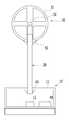
도 1은 본 발명의 일 실시예에 따른 풍향풍속계의 사시도이다.
도 2는 도 1에 도시된 풍향풍속계의 단면도이다.
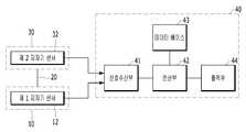
도 3은 도 1에 도시된 풍향풍속계의 구성도이다.
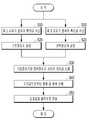
도 4는 도 1에 도시된 풍향풍속계의 데이터 처리부(40)의 연산순서도이다.1 is a perspective view of a wind direction anemometer according to an embodiment of the present invention.
2 is a sectional view of the wind direction anemometer shown in Fig.
3 is a configuration diagram of the wind direction anemometer shown in Fig.
Fig. 4 is a flowchart showing the operation of the
이하에서는 첨부된 도면을 참조하여 본 발명의 실시예들을 상세히 설명한다. 이하에서 설명되는 실시예들은 한 쌍의 자기장센서에서 측정되는 값으로부터 풍향과 풍속을 산출함으로써 바람의 기온이나 소음, 습도 등의 기상환경 변화에 영향을 받지 않으면서 풍향 및 풍속을 측정할 수 있어 측정의 정확도가 높고 저비용 소형화가 가능한 풍향풍속계에 관한 것이다. 이하에서는 한 쌍의 자기장센서를 이용한 풍향풍속계를 간략하게 “풍향풍속계”라 호칭한다.Hereinafter, embodiments of the present invention will be described in detail with reference to the accompanying drawings. The embodiments described below can measure the wind direction and the wind speed without being affected by the change of the weather environment such as wind temperature, noise, and humidity by calculating the wind direction and wind speed from the values measured by the pair of magnetic field sensors, And more particularly, to a wind direction anemometer capable of high accuracy and low cost. Hereinafter, a wind direction anemometer using a pair of magnetic field sensors is simply referred to as a " wind direction anemometer ".
도 1은 본 발명의 일 실시예에 따른 풍향풍속계의 사시도이고, 도 2는 도 1에 도시된 풍향풍속계의 단면도이다. 도 1 및 도 2을 참조하면, 본 실시예에 따른 풍향풍속계는 기준모듈(10), 연결체(20), 변위모듈(30) 및 데이터 처리부(40)로 구성되어 있다. 특히 기준모듈(10)의 내부에는 제 1 지자기센서(12)가 배치되어 있고, 변위모듈(30)의 내부에는 제 2 지자기센서(32)가 배치되어 있다.FIG. 1 is a perspective view of a wind direction anemometer according to an embodiment of the present invention, and FIG. 2 is a sectional view of the wind direction anemometer shown in FIG. Referring to FIGS. 1 and 2, the wind direction and speed anemometer according to the present embodiment includes a
기준모듈(10)은 지면에 고정된 상태로 지구 자기장을 측정하고 측정된 데이터를 외부로 전송한다. 구체적으로, 기준모듈(10)은 사각박스 또는 원통형으로 형성되어 지면에 고정된 케이스(11)와 그 케이스(11)의 바닥에 설치되어 지구 자기장을 측정하는 제 1 지자기센서(12)로 구성되어 있다. 케이스(11)는 자성을 띄지 않는 플라스틱과 같은 비자성 재질로 구성되고, 볼트에 의해 지면에 관통고정될 수도 있고 케이스(11)의 아래 중량이 큰 비자성 물체와 결합되어 있을 수 있다. 또는, 고무빨판이 결합되어 지면과 진공흡착을 통해 지면에 밀착고정될 수도 있다. 제 1 지자기센서(12)는 지구 자기장을 측정하는 센서로 케이스(11)의 바닥 중심에 설치될 수 있다. 제 1 지자기센서(12)는 연산회로를 갖는 데이터 처리부(40)와 전기적으로 연결되어 있으며, 측정된 지구 자기장을 데이터 처리부(40)로 전송한다.The
연결체(20)는 일자형의 봉 형태로 형성되어 지면과 수직하도록 기준모듈(10)의 상면에 결합되어 있다. 상세히, 연결체(20)는 원기둥의 막대 형태로 형성되며, 탄성을 가지는 재질로 구성되어 풍력에 의해 탄성이동된다. 연결체(20)의 하단은 기준모듈(10)와 결합되고 연결체(20)의 상단은 변위모듈(30)과 결합되어 있으며, 도 2에 도시된 바와 같이 연결체(20)의 각 끝단의 외주면에 나사산이 형성될 수 있다. 연결체(20)의 길이와 탄성계수에 대한 정보는 데이터 처리부(40)에 기입력되어 저장되며, 이 정보들은 풍속을 산출하는 과정에서 사용될 수 있다.The connecting
변위모듈(30)은 구 형태로써 연결체(20)의 상단에 결합되어 바람에 의해 흔들리는 상태로 지구 자기장을 측정하고 측정된 데이터를 외부로 전송한다. 구체적으로, 변위모듈(30)은 구 형태의 하우징(31)과 그 하우징(31)의 중심에 설치되어 지구 자기장을 측정하는 제 2 지자기센서(32)로 구성되어 있다. 하우징(31)은 플라스틱 또는 금속재질로 구성되며, 동서남북상하의 모든 방향에서 오는 바람을 직접적으로 받는 부분이다. 제 2 지자기센서(32)는 지구 자기장을 측정하는 지자기센서로써 변위모듈(30)의 하우징(31)의 중심에 설치될 수 있다. 하우징(31)은 도 2에 도시된 바와 같이 구 형태의 정 중앙에 제 2 지자기센서(32)가 삽입될 수 있는 사각박스공간이 형성될 수 있으며, 이를 위해 금형압축 프레스 방식으로 하우징(31)이 제조될 수 있다. 제 2 지자기센서(32)는 연산회로를 갖는 데이터 처리부(40)와 전기적으로 연결되어 있으며, 측정된 지구 자기장을 데이터 처리부(40)로 전송한다.The
데이터 처리부(40)는 기준모듈(10) 및 변위모듈(30)과 전기적으로 연결되어 기준모듈(10) 및 변위모듈(30)로부터 데이터를 수신받는다. 데이터 처리부(40)는 별도의 장치로써 기준모듈(10)의 케이스(11) 외부에 설치될 수도 있고, 도 2에 도시된 바와 같이 기준모듈(10)의 케이스(11) 내부에 배치되어 있을 수 있다. 데이터 처리부(40)는 기준모듈(10)에서 측정된 데이터와 변위모듈(30)에서 측정된 데이터의 차이값을 기반으로 풍향 및 풍속을 산출한다.The
변위모듈(30)이 연결체(20)의 상단에서 어느 한쪽으로 치우쳐지게 설치되는 경우, 한쪽으로 편중된 풍향 및 풍속 데이터가 산출될 수 있다. 따라서, 변위모듈(30)이 어느 한쪽으로 치우져지지 않도록, 연결체(20)는 기준모듈(10)의 케이스(11) 중심과 변위모듈(30)의 하우징(31) 중심을 서로 잇는 일직선 상에 배치되는 것이 바람직하다. 변위모듈(30)이 편중되지 않음에 따라 보다 신뢰성 높은 풍향 및 풍속 데이터를 측정할 수 있다.In the case where the
이를 위한 방안으로, 변위모듈(30)이 연결체(20)의 끝단에 기울어지지 않는 상태로 고정되도록 연결체(20)의 상단에 받침소켓(50)이 결합될 수 있다. 받침소켓(50)은 연결체(20)가 관통가능한 중공이 형성되어 있으며 상면이 하우징(31)의 하면과 대응되게 오목한 곡면으로 형성되고 중공을 기준으로 측단면이 좌우 대칭된 형태로 형성되어 있다. 받침소켓(50)의 상면은 하우징(31)의 하면이 안착되도록 곡률져 하우징(31)의 하면과 밀착되고, 외측면은 하우징(31)의 무게를 분산하면서 안정적으로 지지하기 위해 위에서 아래로 갈수록 둘레가 감소하는 테이퍼진 형상으로 형성될 수 있다. 받침소켓(50)의 중공의 내주면에 나사산이 형성되어 있어 연결체(20)의 상단에 형성된 나사산과 맞물림 체결방식으로 사용자가 원하는 위치에 견고히 결합될 수 있다. 연결체(20)의 상단에 받침소켓(50)이 결합되고 받침소켓(50)의 상면에 하우징(31)이 안착된 상태로 연결체(20)의 상단에 결합됨으로써, 하우징(31)이 어느 한쪽으로 편중되지 않게 고정설치되고 동서남북으로 불어오는 바람에 대해 보다 정확히 풍향과 풍속을 측정할 수 있다.To this end, the receiving
연결체(20)가 바람에 의해 반복적으로 흔들리면, 연결체(20)와 기준모듈(10)이 결합되어 있는 부분이 헐거워지면서 연결체(20)가 탈락될 수도 있다. 이러한 문제를 방지하기 위해, 연결체(20)의 하단에 고정소켓(60)이 추가 결합될 수도 있다. 고정소켓(60)은 연결체(20)가 관통되도록 중공이 형성되어 있으며 기준모듈(10)의 케이스(11) 상부와 면접촉된 상태로 연결체(20)의 하단에 고정결합된다. 고정소켓(60)은 도 2에 도시된 바와 같이 중공의 내주면에 나사산이 형성되어 있어 연결체(20)의 하단의 나사산과 서로 맞물림 체결방식으로 결합될 수 있고, 연결체(20)의 탄성에 영향을 최소화하기 위해 기준모듈(10)의 케이스(11) 내부에 배치될 수 있다.If the connecting
본 실시예인 풍향풍속계는 바람을 직접 받는 야외에 설치되는 장치로써, 기상관측표준화법에 의거하여 지상에서 10m 이상이 되는 곳에 설치됨이 바람직하다. 기준모듈(10)은 평평한 바닥면에 고정되고 구 형태의 외형을 갖는 변위모듈(30)은 풍압을 받아 연결체(20)에 결합된 상태로 이동되는 것으로, 기준모듈(10)의 제 1 지자기센서(12)가 측정한 데이터와 변위모듈(30)의 제 2 지자기센서(32)가 측정한 데이터를 서로 비교하여 그 차이를 기반으로 풍향과 풍속을 산출할 수 있다.The wind direction anemometer according to the present embodiment is installed in the outdoors to receive wind directly, and is preferably installed at a position of 10 m or more from the ground based on the weather observation standardization method. The
도 3은 도 1에 도시된 풍향풍속계의 구성도이다. 도 3을 참조하면, 데이터 처리부(40)는 신호수신부(41), 연산부(42), 데이터 베이스(43) 및 출력부(44)로 구성된다. 데이터 처리부(40)는 소형화된 회로로 구성되어 기준모듈(10)의 케이스(11) 내부에 배치될 수도 있고, 별도의 독립된 장치로 구성되어 기준모듈(10)의 케이스(11) 외부에 설치될 수 있다.3 is a configuration diagram of the wind direction anemometer shown in Fig. 3, the
신호수신부(41)는 기준모듈(10)의 제 1 지자기센서(12) 및 변위모듈(30)의 제 2 지자기센서(32)와 전기적으로 연결되어 측정 데이터를 수신받는다. 신호수신부(41)는 제 1 지자기센서(12) 및 제 2 지자기센서(32)와 유선 또는 무선으로 접속되며 수신받은 측정 데이터를 연산부(42)로 전송한다.The
연산부(42)는 기준모듈(10)에서 수신된 데이터를 기반으로 서로 직교하는 X축, Y축, Z축으로 구성된 기준좌표계를 설정하고, 변위모듈(30)에서 수신된 데이터를 기반으로 서로 직교하는 X축, Y축, Z축으로 구성된 변위좌표계를 설정한다.The
기준좌표계는 기준모듈(10)이 지면에 고정되어 있어 풍향 및 풍속에 따라 변하지 않는 좌표축인 반면, 변위좌표계는 변위모듈(30)이 바람에 의해 움직이게 되어 풍향 및 풍속에 의해 각축의 기울기가 변하는 좌표축이다. 연산부(42)는 기준좌표계의 각 축과 상기 변위좌표계의 각 축 사이에 발생된 경사의 유무를 통해 풍향을 산출하고, 경사각의 유무와 크기를 이용하여 풍향 및 풍속을 산출할 수 있다.The reference coordinate system is a coordinate axis which is fixed on the ground and is not changed according to the wind direction and the wind speed. On the other hand, the displacement coordinate system is a coordinate axis in which the
데이터 베이스(43)는 연결체(20)의 탄성계수에 대한 정보, 연결체(20)의 길이에 대한 정보, 바람의 온도에 따른 공기 밀도에 대한 정보, 공기의 풍압계수에 대한 정보, 하우징(31)의 반경에 대한 정보 등의 풍향풍속 산출에 필요한 배경 데이터가 저장되어 연산부(42)의 요청에 의해 필요한 데이터를 전송한다. 데이터 베이스(43)는 외부 입력에 의해 저장된 배경 데이터의 추가, 삭제, 수정과 같이 업데이트가 가능하며, 클라우드 서버와 같은 외부망과 연동될 수도 있다.The
출력부(44)는 연산부(42)에서 산출된 풍향 및 풍속 결과값을 수신받아 사용자가 볼 수 있는 디스플레이 장치로 신호를 전송한다. 출력부(44)는 산출된 풍향 및 풍속 결과값을 시각적 데이터로 변환할 수 있으며 이러한 변환은 공지의 방식을 이용할 수도 있다.The
도 4는 도 1에 도시된 풍향풍속계의 데이터 처리부(40)의 연산순서도이다.Fig. 4 is a flowchart showing the operation of the
단계 S10에서, 신호수신부(41)는 제 1 지자기센서(12)의 측정값을 수신하여 연산부(42)로 전송한다. 또, 단계 S11에서, 신호수신부(41)는 제 2 지자기센서(32)의 측정값을 수신하여 연산부(42)로 전송한다. 제 1 지자기센서(12)로부터 수신되는 측정값은 일정하며, 제 2 지자기센서(32)로부터 수신되는 측정값은 바람에 의해 실시간으로 변경된다. 측정값은 유선으로 수신받을 수도 있고, 무선으로 접속되어 수신받을 수도 있다.In step S10, the
단계 S20에서, 연산부(42)는 제 1 지자기센서(12)의 측정값을 기반으로 3차원의 각 축이 서로 수직한 기준좌표계를 설정한다. 또, 단계 S21에서, 연산부(42)는 제 2 지자기센서(32)의 측정값을 기반으로 3차원의 각 축이 서로 수직한 변위좌표계를 설정한다. 바람을 측정하기 전, 연결체(20)는 곧게 직립되어 있는 상태이므로 변위좌표계의 각 축이 기준좌표계의 각 축에 평행한 초기상태를 갖는다.In step S20, the
단계 S30에서, 연산부(42)는 데이터 베이스(43)의 배경 데이터와 기준좌표계 및 변위좌표계 사이에 발생되는 차이값을 계산한다. 여기서 차이값은 특정 좌표 사이의 방향성을 나타내는 벡터값일 수 있고, 좌표축 간 경사각일 수 있다.In step S30, the
단계 S40에서, 연산부(42)는 단계 S30에서 계산된 차이값을 기반으로 풍향과 풍속을 산출한다. 연결체(20)는 그 끝단에 결합된 변위모듈(30)이 바람을 받으면 연결체(20)가 휘어지게 되면서 변위모듈(30)의 내부에 배치된 제 2 지자기센서(32)의 측정값이 달라지게 된다. 평평한 지면에 고정된 제 1 지자기센서(12)의 측정값과 기울어진 제 2 지자기센서(32)의 측정값을 서로 비교하여 그 차이로부터 바람이 불어오는 방향을 산출할 수 있다. 예컨대, 기준좌표계와 초기의 변위좌표계 모두 X축이 남쪽을 향하고 Y축이 서쪽을 향하는 경우, 동쪽에서 불어오는 바람이 불어오면 변위모듈(30)은 서쪽으로 기울어지게 된다. 이 경우, 남쪽을 향하는 X축은 평행한 상태를 유지하는 반면, Y축과 Z축이 서로 어긋나게 경사각이 발생하게 된다. 이러한 방식으로 기준좌표계와 변위좌표계의 차이로부터 동서남북 방향에서 불어오는 바람의 방향을 산출할 수 있다.In step S40, the calculating
풍속이 강하여 변위모듈(30)이 받는 풍력이 강하면, 연결체(20)가 휘어지는 정도가 증가하고 제 2 지자기센서(32)의 기울어짐에 의해 변위좌표계와 기준좌표계 사이의 차이 또한 커지게 된다. 변위모듈(30)의 하우징(31)이 받는 풍압은 하우징(31)의 단위 면적 당 받는 풍력으로써, 연결체(20)가 휘어지면서 갖는 탄성력으로부터 풍력을 도출할 수 있다. 즉, 연결체(20)가 바람에 의해 휘어지면서 발생하는 탄성력이 변위모듈(30)의 하우징(31)이 받는 풍력과 평행관계에 있으므로, 연결체(20)의 탄성력이 풍력과 같다고 볼 수 있다. 연결체(20)의 탄성력은 연결체(20)의 탄성계수와 휨모멘트 관계를 이용하여 산출할 수 있다. 아니면, 변위모듈(30)의 내부에 가속도센서를 설치하여 변위모듈(30)의 질량값과 가속도센서에서 측정된 가속도를 이용하여 탄성력을 직접 측정할 수도 있다.When the wind force is strong and the wind force received by the
산출된 풍력으로부터 베르누이 방정식을 이용한 아래 [수학식 1]과 같이 풍속을 산출할 수 있다.The wind speed can be calculated from the calculated wind force using the Bernoulli equation as shown in the following equation (1).
[수학식 1][Equation 1]

수학식 1에서, P는 하우징(31)이 받는 풍압이고, F는 연결체(20)가 발휘하는 탄성력이고, A는 하우징(31)의 단면적이고, C는 바람의 풍압계수이고, ρ는 공기의 밀도이고, v는 풍속이다. 풍압계수C는 풍압이 대기압보다 높을 때는 양수이고 풍압이 대기압보다 낮을 때는 음수이며 하우징(31)의 구 형태와 하우징(31)으로 불어오는 바람의 방향, 주위의 조건에 따라 실험적으로 구해지는 상수이다. 공기의 밀도ρ는 온도에 따라 달라지는 계수로써 공지된 수치를 이용하여 본 실시예가 설치되는 환경의 온도에 맞게 설정될 수 있다. 연산부(42)는 데이터 베이스(43)로부터 풍속의 산출에 필요한 배경 데이터를 수신받을 수 있다.Where P is the wind pressure to which the
더하여, 연산부(42)는 원기둥 형태의 연결체(20)가 받는 풍력, 하우징(31) 자체의 무게에 의한 관성저항을 고려하여 오차를 보정하면 보다 정확한 풍속을 구할 수 있다. 예컨대, 연결체(20)가 바람을 받는 면적이 클수록, 또 하우징(31) 자체의 무게가 클수록 증가하는 보정계수를 곱하여 오차를 감소시킬 수 있다. 보정계수는 실험값으로써 다른 풍향풍속계와 비교실험하여 정해질 수 있다.In addition, the
단계 S50에서, 연산부(42)는 산출된 풍향 및 풍속 결과값을 출력부(44)로 전송한다. 이후, 출력부(44)는 소리, 시각 데이터 등 사용자가 인지할 수 있는 형태의 데이터로 외부에 출력할 수 있다.In step S50, the
더하여, 도 1 및 도 2는 지면 상에 기준모듈(10)이 고정되고 그 위로 연결체(20)와 변위모듈(30)이 형성된 것을 도시하였으나, 설치환경과 필요에 따라 기준모듈(10)이 천정에 고정되고 변위모듈(30)이 그 아래에 연결체(20)로 매달리도록 설치될 수도 있다. 예컨대, 기준모듈(10)이 풍동시험실과 시설물이나 건물 내부의 천정과 같은 평평한 면에 고정설치되고 기준모듈(10)에서 아래로 연결체(20)가 설치되고 그 연결체(20)의 하단에 변위모듈(30)이 고정될 수 있다.1 and 2 illustrate that the
이러한 구조는, 변위모듈(30)이 자체 하중에 의해 항상 기준모듈(10)과 일직선 아래 위치하려는 복원성을 가짐으로써 연결체(20)를 비탄성재질로도 구현할 수 있다. 연결체(20)는 강성의 와이어나 폴리 카보네이트로도 구성이 가능하며, 연결체(20)의 탄성계수를 연산과정에 산입시키지 않고도 변위모듈(30)의 하중만으로 풍력을 산출할 수 있는 점에서 풍향 및 풍속을 산출하는 연산과정을 매우 간소해지는 장점이 있다.Such a structure can realize the
종래기술인 대한민국 특허공개번호 제10-2001-0110286호의 ‘풍향 및 풍속 측정기’는 일자 막대형태의 탄성체에 서로 수직하게 두 스트레인게이지를 부착하여 바람에 의해 탄성체가 휘어지면서 저항값이 변형되는 점을 이용하여 풍압을 측정하는 방식이다. 하지만, 마감캡의 크기와 형상에 따라 바람이 받는 정도가 상이하며 탄성체가 기울어짐에 의해 마감캡의 수직단면적이 변하여 풍력이 정확히 측정될 수 없는 점에 오차가 발생된다. 또한, 스트레인게이지 센서가 작아질수록 노이즈가 심해지는 특성상 일정 크기 이상의 스트레인게이지 센서가 탄성체에 부착되어야 하며, 스트레인게이지 센서의 크기가 커지는 만큼 탄성체 끝단이 무거워져 관성저항 또한 증가함에 따라 풍속의 오차가 발생된다. 스트레인게이지의 센서를 소형화하면 그에 따른 가격이 급상승하여 제조단가가 올라가는 점이 있고, 원기둥형태의 탄성체에 두 스트레인게이지를 정확히 수직하게 붙여야 성능이 발휘되는 구조상 스트레인게이지를 부착하는 작업자의 노하우에 따라 측정성능이 좌우되는 점이 있다.Korean Patent Laid-Open Publication No. 10-2001-0110286 discloses a wind direction and wind speed measuring device in which two strain gauges are attached perpendicularly to an elongated rod-like elastic body, and a resistance value is deformed due to bending of the elastic body by the wind To measure the wind pressure. However, depending on the size and shape of the finishing cap, the degree of wind is different, and an inclination of the elastic body causes an error in that the vertical cross-sectional area of the finishing cap changes and the wind force can not be accurately measured. In addition, as the strain gauge sensor becomes smaller, the strain gauge sensor of a certain size or more must be attached to the elastic body due to the characteristic of increasing the noise. As the size of the strain gauge sensor becomes larger, the end of the elastic body becomes heavy and the inertia resistance also increases. . The strain gauge sensor has to be miniaturized to increase the manufacturing cost, and the manufacturing cost is increased. The strain gauge is required to be stuck vertically to the cylindrical elastic body so that the performance of the strain gauge is improved. There is a point that this is influenced.
다른 종래기술인 일본 특허등록번호 특개평6-48274의 ‘풍향 풍속 측정 장치’는 일자 봉 형태의 막대 끝에 구형의 수풍체를 설치하고 그 막대의 내부에 동심으로 이격된 공간을 갖는 전극을 형성하여 막대의 휘어짐에 의해 측정되는 전극 사이의 전압변화값으로 풍향과 풍속을 측정하는 방식이다. 이러한 구조는, 수풍체가 움직일 수 있는 정도가 전극 사이의 간격 이내이므로 측정범위가 좁은 단점이 있다. 이를 보완하기 위해 자석을 부착하여 척력을 이용하지만, 자석이 결합된 만큼 수풍체의 질량이 증가하고 전극 사이의 거리가 감소하여 좁은 측정범위를 해결하기에는 한계가 있다.Another prior art Japanese Patent Registration No. 6-48274, entitled " Wind direction wind speed measuring device ", is a device in which a spherical water-receiving body is provided at the end of a bar-shaped rod, and an electrode having a space concentrically spaced inside the rod is formed, The wind direction and the wind speed are measured by the voltage change value between the electrodes measured by the warping of the wind direction. Such a structure is disadvantageous in that the measurement range is narrow because the degree to which the water-permeable body can move is within the interval between the electrodes. In order to compensate for this, a repulsive force is applied by attaching a magnet. However, there is a limit to solve a narrow measurement range because the mass of the water-receiving body increases as the magnets are coupled and the distance between the electrodes decreases.
또 다른 종래기술인 한국특허 등록공보 제10-1405853호의 ‘압전소자를 이용한 풍향풍속계’는 구형상의 몸체부와 그 외주면에 방사상으로 다수의 캔틸레버형 측정부를 설치하여 바람에 의해 탄성 변형되면서 발생되는 전압을 측정하여 풍향과 풍속을 측정하고 있다. 이러한 구조는 방사상으로 형성된 다수의 캔틸레버가 와류를 형성하여 풍향 및 풍속에 영향을 주고, 캔틸레버 자체의 형상이나 설치 개수에 따라 측정오차가 달라지므로 데이터 신뢰성에 악영향을 주게된다. 또한, 각 캔틸레버마다 필수적으로 고가의 압전소자를 사용하는 점에서 풍향풍속계의 단가를 낮추기에 한계점이 존재한다.Another prior art Korean Patent Registration No. 10-1405853, entitled " Wind direction anemometer using piezoelectric elements ", has a spherical body portion and a plurality of cantilever-type measurement portions radially arranged on the outer circumferential surface thereof to measure a voltage generated by elastic deformation And the wind direction and wind speed are measured. In such a structure, a plurality of radially formed cantilevers forms a vortex, which affects the wind direction and wind speed, and the measurement error varies depending on the shape of the cantilever itself and the number of installed cantilevers, thereby adversely affecting data reliability. Further, there is a limitation in lowering the unit price of the wind direction anemometer in that the expensive piezoelectric element is necessarily used for each cantilever.
본 실시예는 한 쌍의 지자기센서를 서로 이격되게 배치하고 바람에 의해 두 지자기센서에서 측정되는 최초의 좌표값이 서로 어긋나게 되는 점을 이용하였다. 바람의 온도, 습도 등의 기상 환경 변화에 관계없이 급격한 변화가 일어나지 않는 지구 자기장을 측정함으로써 위 요인들에 따른 오차발생을 방지할 수 있고, 설령 지구자기장이 변화가 일어나더라도 한 쌍의 지자기센서 중 어느 하나가 기준이 되는 점에서 그 오차가 극히 미약하여 정확한 풍향 및 풍속의 측정이 가능하다. 또한, 응답특성이 빠른 지자기센서의 특성상 실시간으로 미세하게 변하는 풍향 및 풍속을 실시간으로 측정할 수 있다.In this embodiment, a pair of geomagnetic sensors are disposed apart from each other, and the first coordinate values measured by the two geomagnetic sensors are deviated from each other by the wind. It is possible to prevent the occurrence of errors according to the above factors by measuring the earth magnetic field in which sudden change does not occur regardless of the change of the weather environment such as wind temperature and humidity and even if the earth magnetic field changes, It is possible to measure the wind direction and the wind speed accurately because the error is extremely small at a point where any one is a standard. In addition, due to the characteristics of the geomagnetic sensor, which has a fast response characteristic, it is possible to measure the wind direction and wind speed which change in real time in real time.
또한, 종래기술과 같이 고비용의 압전소자를 사용할 필요없이 저가의 지자기센서를 사용함으로써 비교적 저렴한 풍향풍속계를 제조할 수 있다. 게다가, 본 실시예인 풍향풍속계에 과도한 부피가 요구되지 않으면서 지자기센서가 낮은 전력으로 구동이 가능한 점에서 휴대가 가능할 정도로 소형화가 가능하다. 풍향풍속의 측정을 위해서 단순히 평지에 놓아 바람에 노출시키면 되므로, 별도의 대형장비나 복잡한 설치방법이 요구되지 않는 편리성이 있다. 이러한 본 실시예는 실외에 설치될 수도 있고 풍동시험실과 같은 건물의 평평한 천정면에 설치되어 풍향 및 풍속을 테스트하는 장치로도 활용될 수 있다.In addition, it is possible to manufacture a relatively low-wind directional anemometer by using a low-cost geomagnetic sensor without using a high-cost piezoelectric element as in the prior art. In addition, since the geomagnetic sensor can be driven with low power without requiring an excessive volume of the wind direction anemometer, which is the present embodiment, it can be miniaturized enough to carry. For measurement of wind direction wind speed, it can be simply placed on a flat surface and exposed to the wind, so there is no need for a separate large equipment or complicated installation method. The present embodiment may be installed outdoors or installed on a flat ceiling surface of a building such as a wind tunnel test room to be used as an apparatus for testing wind direction and wind speed.
이제까지 본 발명에 대하여 바람직한 실시예들을 중심으로 살펴보았다. 본 발명이 속하는 기술 분야에서 통상의 지식을 가진 자는 본 발명이 본 발명의 본질적인 특성에서 벗어나지 않는 범위에서 변형된 형태로 구현될 수 있음을 이해할 수 있을 것이다. 그러므로 개시된 실시예들은 한정적인 관점이 아니라 설명적인 관점에서 고려되어야 한다. 본 발명의 범위는 전술한 설명이 아니라 특허청구범위에 나타나 있으며, 그와 동등한 범위 내에 있는 모든 차이점은 본 발명에 포함된 것으로 해석되어야 할 것이다.The present invention has been described above with reference to preferred embodiments. It will be understood by those skilled in the art that various changes in form and details may be made therein without departing from the spirit and scope of the invention as defined by the appended claims. Therefore, the disclosed embodiments should be considered in an illustrative rather than a restrictive sense. The scope of the present invention is defined by the appended claims rather than by the foregoing description, and all differences within the scope of equivalents thereof should be construed as being included in the present invention.
10 ... 기준모듈11 ... 케이스
12 ... 제 1 지자기센서
20 ... 연결체
30 ... 변위모듈31 ... 하우징
32 ... 제 2 지자기센서
40 ... 데이터 처리부41 ... 신호수신부
42 ... 연산부43 ... 데이터 베이스
44 ... 출력부
50 ... 받침소켓
60 ... 고정소켓10 ...
12 ... 1st geomagnetic sensor
20 ... connector
30 ...
32 ... 2nd geomagnetic sensor
40 ...
42 ... operating
44 ... output section
50 ... bearing socket
60 ... fixed socket
Claims (7)
Translated fromKorean일자형의 봉 형태로 형성되어 지면과 수직하도록 일단이 상기 기준모듈(10)에 결합된 연결체(20);
구 형태로써 상기 연결체(20)의 타단에 결합되어 바람에 의해 흔들리는 상태로 지구 자기장을 측정하고 측정된 데이터를 외부로 전송하는 변위모듈(30); 및
상기 기준모듈(10) 및 상기 변위모듈(30)과 전기적으로 연결되어 상기 기준모듈(10) 및 상기 변위모듈(30)로부터 데이터를 수신받고, 상기 기준모듈(10)에서 측정된 데이터와 상기 변위모듈(30)에서 측정된 데이터의 차이값을 기반으로 풍향 및 풍속을 산출하는 데이터 처리부(40)를 포함하는 풍향풍속계.A reference module 10 for measuring a geomagnetic field while being fixed on a ground or a flat ceiling face and transmitting the measured data to the outside;
A connecting body 20 formed in a straight bar shape and having one end coupled to the reference module 10 so as to be perpendicular to the ground;
A displacement module (30) coupled to the other end of the connector (20) in a spherical shape, measuring a geomagnetic field in a swinging state by the wind and transmitting the measured data to the outside; And
And a displacement module (30) which is electrically connected to the reference module (10) and the displacement module (30) to receive data from the reference module (10) and the displacement module (30) And a data processing unit (40) for calculating the wind direction and the wind speed based on the difference value of the data measured by the module (30).
상기 기준모듈(10)은 사각박스 또는 원통형으로 형성되어 지면 또는 천정면에 고정된 케이스(11)와, 상기 케이스(11)의 내부에 설치되어 지구 자기장을 측정하는 제 1 지자기센서(12)를 포함하고,
상기 변위모듈(30)은 구 형태의 하우징(31)과, 상기 하우징(31)의 내부에 설치되어 지구 자기장을 측정하는 제 2 지자기센서(32)를 포함하고,
상기 연결체(20)는 상기 기준모듈(10)의 케이스(11) 중심과 상기 변위모듈(30)의 하우징(31) 중심을 서로 잇는 일직선상에 배치되는 것을 특징으로 하는 풍향풍속계.The method according to claim 1,
The reference module 10 includes a case 11 formed in a rectangular box or a cylindrical shape and fixed to a ground or a ceiling surface, a first geomagnetic sensor 12 installed inside the case 11 to measure a geomagnetic field, Including,
The displacement module 30 includes a spherical housing 31 and a second geomagnetic sensor 32 installed inside the housing 31 for measuring a geomagnetic field,
Wherein the connecting body 20 is disposed on a straight line connecting the center of the case 11 of the reference module 10 and the center of the housing 31 of the displacement module 30. [
상기 데이터 처리부(40)는,
상기 기준모듈(10)에서 수신된 데이터를 기반으로 서로 직교하는 X축, Y축, Z축으로 구성된 기준좌표계를 설정하고, 상기 변위모듈(30)에서 수신된 데이터를 기반으로 서로 직교하는 X축, Y축, Z축으로 구성된 변위좌표계를 설정하고,
상기 기준좌표계의 각 축과 상기 변위좌표계의 각 축 사이에 발생된 차이를 이용하여 풍향 및 풍속을 산출하는 것을 특징으로 하는 풍향풍속계.3. The method of claim 2,
The data processing unit (40)
A reference coordinate system including X, Y, and Z axes orthogonal to each other is set based on data received from the reference module 10, and an X-axis , The Y-axis and the Z-axis,
And the wind direction and the wind speed are calculated by using a difference generated between each axis of the standard coordinate system and each axis of the displacement coordinate system.
상기 데이터 처리부(40)는, 상기 연결체(20)의 탄성계수에 대한 정보와 상기 기준좌표계와 상기 변위좌표계의 각 축마다 발생된 차이값을 이용하여 상기 연결체(20)의 탄성력값을 산출한 뒤, 상기 탄성력값을 기반으로 상기 하우징(31)이 받는 풍력 및 풍속을 산출하고,
상기 기준좌표계와 상기 변위좌표계의 각 축마다 발생된 차이값을 이용하여 풍향을 산출하는 것을 특징으로 하는 풍향풍속계.The method of claim 3,
The data processing unit 40 calculates the elastic force value of the connector 20 by using the information about the elastic modulus of the connector 20 and the difference value generated for each axis of the reference coordinate system and the displacement coordinate system Then, based on the elastic force value, the wind force and the wind speed received by the housing 31 are calculated,
Wherein the wind direction is calculated using the reference coordinate system and a difference value generated for each axis of the displacement coordinate system.
상기 데이터 처리부(40)는, 상기 연결체(20)의 수직 단면적 또는 상기 변위모듈(30)의 무게에 따라 결정되는 보정계수를 이용하여 산출된 풍속을 보정하는 풍향풍속계.5. The method of claim 4,
The data processing unit (40) corrects the wind speed calculated using a correction factor determined according to the vertical cross-sectional area of the connector (20) or the weight of the displacement module (30).
상기 연결체(20)가 관통가능한 중공이 형성되어 있으며 상기 중공을 기준으로 측단면이 좌우 대칭된 형태로 형성되고, 상기 하우징(31)의 외주면에 접촉되는 면이 구 형태의 상기 하우징(31)에 대응되게 오목한 곡면으로 형성된 받침소켓(50)를 포함하고,
상기 연결체(20)의 타단에 상기 받침소켓(50)이 결합되고 상기 받침소켓(50)에 상기 하우징(31)이 접촉된 상태로 상기 연결체(20)의 상단에 결합되는 풍향풍속계.3. The method of claim 2,
A side surface of the housing 31 is symmetrical with respect to the hollow, and a surface of the housing 31, which is in contact with the outer circumferential surface of the housing 31, (50) formed in a concavely curved surface corresponding to the concave curved surface,
Wherein the connecting body is coupled to the other end of the connecting body and coupled to the upper end of the connecting body in a state where the housing is in contact with the receiving socket.
상기 연결체(20)가 관통가능한 중공이 형성되어 있으며 상기 중공을 기준으로 측단면이 좌우 대칭된 형태로 형성되고, 상기 케이스(11)와 접촉되는 면이 평평한 평면으로 형성된 고정소켓(60)을 포함하고,
상기 연결체(20)의 일단에 상기 고정소켓(60)이 결합되고 상기 고정소켓(60)과 상기 케이스(11)가 접촉된 상태로 상기 연결체(20)가 바람에 의해 진동하는 것을 특징으로 하는 풍향풍속계.3. The method of claim 2,
A fixing socket (60) having a hollow surface through which the connection body (20) can be inserted, a side surface of which is formed symmetrically with respect to the hollow and which is in contact with the case (11) Including,
The fixing member 60 is coupled to one end of the connecting member 20 and the connecting member 20 is vibrated by the wind while the fixing socket 60 and the case 11 are in contact with each other. Wind direction anemometer.
Priority Applications (1)
| Application Number | Priority Date | Filing Date | Title |
|---|---|---|---|
| KR1020180080159AKR101985330B1 (en) | 2018-07-10 | 2018-07-10 | Anemometer using a pair of magnetic field sensor |
Applications Claiming Priority (1)
| Application Number | Priority Date | Filing Date | Title |
|---|---|---|---|
| KR1020180080159AKR101985330B1 (en) | 2018-07-10 | 2018-07-10 | Anemometer using a pair of magnetic field sensor |
Publications (1)
| Publication Number | Publication Date |
|---|---|
| KR101985330B1true KR101985330B1 (en) | 2019-06-03 |
Family
ID=66848966
Family Applications (1)
| Application Number | Title | Priority Date | Filing Date |
|---|---|---|---|
| KR1020180080159AActiveKR101985330B1 (en) | 2018-07-10 | 2018-07-10 | Anemometer using a pair of magnetic field sensor |
Country Status (1)
| Country | Link |
|---|---|
| KR (1) | KR101985330B1 (en) |
Cited By (1)
| Publication number | Priority date | Publication date | Assignee | Title |
|---|---|---|---|---|
| CN110261637A (en)* | 2019-08-05 | 2019-09-20 | 贵州商学院 | A kind of airspeedometer fixed frame |
Citations (4)
| Publication number | Priority date | Publication date | Assignee | Title |
|---|---|---|---|---|
| JPS6381271A (en)* | 1986-09-25 | 1988-04-12 | Meisei Electric Co Ltd | Method and device for measuring wind direction and wind speed |
| JPH0523160U (en)* | 1991-09-02 | 1993-03-26 | 鈴木 茂 | Magnetic field probe |
| JP2004500554A (en)* | 1999-10-08 | 2004-01-08 | ファースト テクノロジー アーゲー | Accelerometer |
| US20160113092A1 (en)* | 2013-11-21 | 2016-04-21 | General Electric Company | Luminaire associate |
- 2018
- 2018-07-10KRKR1020180080159Apatent/KR101985330B1/enactiveActive
Patent Citations (4)
| Publication number | Priority date | Publication date | Assignee | Title |
|---|---|---|---|---|
| JPS6381271A (en)* | 1986-09-25 | 1988-04-12 | Meisei Electric Co Ltd | Method and device for measuring wind direction and wind speed |
| JPH0523160U (en)* | 1991-09-02 | 1993-03-26 | 鈴木 茂 | Magnetic field probe |
| JP2004500554A (en)* | 1999-10-08 | 2004-01-08 | ファースト テクノロジー アーゲー | Accelerometer |
| US20160113092A1 (en)* | 2013-11-21 | 2016-04-21 | General Electric Company | Luminaire associate |
Cited By (2)
| Publication number | Priority date | Publication date | Assignee | Title |
|---|---|---|---|---|
| CN110261637A (en)* | 2019-08-05 | 2019-09-20 | 贵州商学院 | A kind of airspeedometer fixed frame |
| CN110261637B (en)* | 2019-08-05 | 2021-06-22 | 贵州商学院 | Anemometer fixing frame |
Similar Documents
| Publication | Publication Date | Title |
|---|---|---|
| CN102175887B (en) | Mobile ultrasonic anemometer and method for measuring wind speed and direction | |
| JP5352039B2 (en) | Shape acceleration measuring apparatus and method | |
| US10317422B2 (en) | Multi-directional fluid velocity measurement device (FVMD) | |
| JP5386698B2 (en) | Indoor position detector | |
| CN1054196C (en) | Sensing device | |
| CN104215229B (en) | RTK device adjusting method, RTK device adjusting system and RTK measuring method | |
| JP6893678B2 (en) | Wind measuring device | |
| KR101985330B1 (en) | Anemometer using a pair of magnetic field sensor | |
| JP2011033609A (en) | Indoor position detector | |
| CN201984080U (en) | Movable type ultrasonic wave anemorumbograph | |
| CN101893645B (en) | Ultrasonic wind speed and direction measuring device | |
| CN206696304U (en) | Wind speed wind direction sensor | |
| CN112730889B (en) | Novel wind direction measuring system | |
| JPH0648274B2 (en) | Wind direction / speed measuring device | |
| CN112964899B (en) | A method and device for measuring air velocity | |
| CN106405147B (en) | A kind of ultrasonic transducer surveys wind array and its wind detection method | |
| CN106931955B (en) | Theodolite compass for geological work | |
| JP4893021B2 (en) | Magnetic sensor control device, magnetic measurement device, offset setting method and program | |
| CN211785612U (en) | Wind direction measuring device and system | |
| CN209707539U (en) | A kind of nanoscale gas flow transducer | |
| JPH09304422A (en) | Anemometer | |
| CN113970798A (en) | Lightning locator with very low frequency band | |
| US3572116A (en) | Semiconductor wind speed and direction sensor | |
| CN106813682B (en) | A four-way airborne angle correction device and correction method | |
| JP6931953B1 (en) | Wind speed measurement method using an ultrasonic anemometer and the ultrasonic anemometer |
Legal Events
| Date | Code | Title | Description |
|---|---|---|---|
| PA0109 | Patent application | Patent event code:PA01091R01D Comment text:Patent Application Patent event date:20180710 | |
| PA0201 | Request for examination | ||
| E701 | Decision to grant or registration of patent right | ||
| PE0701 | Decision of registration | Patent event code:PE07011S01D Comment text:Decision to Grant Registration Patent event date:20190508 | |
| GRNT | Written decision to grant | ||
| PR0701 | Registration of establishment | Comment text:Registration of Establishment Patent event date:20190528 Patent event code:PR07011E01D | |
| PR1002 | Payment of registration fee | Payment date:20190528 End annual number:3 Start annual number:1 | |
| PG1601 | Publication of registration | ||
| PR1001 | Payment of annual fee | Payment date:20220401 Start annual number:4 End annual number:4 | |
| PR1001 | Payment of annual fee | Payment date:20230316 Start annual number:5 End annual number:5 | |
| PR1001 | Payment of annual fee | Payment date:20240509 Start annual number:6 End annual number:6 | |
| PR1001 | Payment of annual fee | Payment date:20250312 Start annual number:7 End annual number:7 |