KR101975751B1 - Curbs for measuring the depth of saliva in urban center - Google Patents
Curbs for measuring the depth of saliva in urban centerDownload PDFInfo
- Publication number
- KR101975751B1 KR101975751B1KR1020180135293AKR20180135293AKR101975751B1KR 101975751 B1KR101975751 B1KR 101975751B1KR 1020180135293 AKR1020180135293 AKR 1020180135293AKR 20180135293 AKR20180135293 AKR 20180135293AKR 101975751 B1KR101975751 B1KR 101975751B1
- Authority
- KR
- South Korea
- Prior art keywords
- space
- water level
- measuring
- level meter
- main body
- Prior art date
- Legal status (The legal status is an assumption and is not a legal conclusion. Google has not performed a legal analysis and makes no representation as to the accuracy of the status listed.)
- Active
Links
- 210000003296salivaAnatomy0.000title1
- XLYOFNOQVPJJNP-UHFFFAOYSA-NwaterSubstancesOXLYOFNOQVPJJNP-UHFFFAOYSA-N0.000claimsabstractdescription67
- 238000007654immersionMethods0.000claimsabstractdescription27
- 230000008878couplingEffects0.000claimsdescription11
- 238000010168coupling processMethods0.000claimsdescription11
- 238000005859coupling reactionMethods0.000claimsdescription11
- 238000005192partitionMethods0.000claimsdescription6
- 238000000034methodMethods0.000claimsdescription3
- 230000000149penetrating effectEffects0.000claimsdescription2
- 230000001965increasing effectEffects0.000description5
- 238000010276constructionMethods0.000description2
- 238000003780insertionMethods0.000description2
- 230000037431insertionEffects0.000description2
- 238000012986modificationMethods0.000description2
- 230000004048modificationEffects0.000description2
- 230000002265preventionEffects0.000description2
- 238000011001backwashingMethods0.000description1
- 238000004891communicationMethods0.000description1
- 238000007796conventional methodMethods0.000description1
- 238000001514detection methodMethods0.000description1
- 238000011161developmentMethods0.000description1
- 239000003651drinking waterSubstances0.000description1
- 235000020188drinking waterNutrition0.000description1
- 238000005516engineering processMethods0.000description1
- 230000002708enhancing effectEffects0.000description1
- 238000005259measurementMethods0.000description1
- 238000012544monitoring processMethods0.000description1
- 230000003287optical effectEffects0.000description1
- 230000002093peripheral effectEffects0.000description1
- 239000012780transparent materialSubstances0.000description1
- 238000012795verificationMethods0.000description1
- 238000010792warmingMethods0.000description1
Images


Classifications
- G—PHYSICS
- G01—MEASURING; TESTING
- G01F—MEASURING VOLUME, VOLUME FLOW, MASS FLOW OR LIQUID LEVEL; METERING BY VOLUME
- G01F23/00—Indicating or measuring liquid level or level of fluent solid material, e.g. indicating in terms of volume or indicating by means of an alarm
- G01F23/14—Indicating or measuring liquid level or level of fluent solid material, e.g. indicating in terms of volume or indicating by means of an alarm by measurement of pressure
- G01F23/18—Indicating, recording or alarm devices actuated electrically
- G—PHYSICS
- G01—MEASURING; TESTING
- G01F—MEASURING VOLUME, VOLUME FLOW, MASS FLOW OR LIQUID LEVEL; METERING BY VOLUME
- G01F23/00—Indicating or measuring liquid level or level of fluent solid material, e.g. indicating in terms of volume or indicating by means of an alarm
- G01F23/14—Indicating or measuring liquid level or level of fluent solid material, e.g. indicating in terms of volume or indicating by means of an alarm by measurement of pressure
- G01F23/16—Indicating, recording, or alarm devices being actuated by mechanical or fluid means, e.g. using gas, mercury, or a diaphragm as transmitting element, or by a column of liquid
- G01F23/161—Indicating, recording, or alarm devices being actuated by mechanical or fluid means, e.g. using gas, mercury, or a diaphragm as transmitting element, or by a column of liquid for discrete levels
- E—FIXED CONSTRUCTIONS
- E01—CONSTRUCTION OF ROADS, RAILWAYS, OR BRIDGES
- E01C—CONSTRUCTION OF, OR SURFACES FOR, ROADS, SPORTS GROUNDS, OR THE LIKE; MACHINES OR AUXILIARY TOOLS FOR CONSTRUCTION OR REPAIR
- E01C11/00—Details of pavings
- E01C11/22—Gutters; Kerbs ; Surface drainage of streets, roads or like traffic areas
- E01C11/221—Kerbs or like edging members, e.g. flush kerbs, shoulder retaining means ; Joint members, connecting or load-transfer means specially for kerbs
- E01C11/222—Raised kerbs, e.g. for sidewalks ; Integrated or portable means for facilitating ascent or descent
- G—PHYSICS
- G01—MEASURING; TESTING
- G01F—MEASURING VOLUME, VOLUME FLOW, MASS FLOW OR LIQUID LEVEL; METERING BY VOLUME
- G01F23/00—Indicating or measuring liquid level or level of fluent solid material, e.g. indicating in terms of volume or indicating by means of an alarm
- G—PHYSICS
- G01—MEASURING; TESTING
- G01F—MEASURING VOLUME, VOLUME FLOW, MASS FLOW OR LIQUID LEVEL; METERING BY VOLUME
- G01F23/00—Indicating or measuring liquid level or level of fluent solid material, e.g. indicating in terms of volume or indicating by means of an alarm
- G01F23/14—Indicating or measuring liquid level or level of fluent solid material, e.g. indicating in terms of volume or indicating by means of an alarm by measurement of pressure
- G01F23/18—Indicating, recording or alarm devices actuated electrically
- G01F23/185—Indicating, recording or alarm devices actuated electrically for discrete levels
- G—PHYSICS
- G01—MEASURING; TESTING
- G01F—MEASURING VOLUME, VOLUME FLOW, MASS FLOW OR LIQUID LEVEL; METERING BY VOLUME
- G01F23/00—Indicating or measuring liquid level or level of fluent solid material, e.g. indicating in terms of volume or indicating by means of an alarm
- G01F23/22—Indicating or measuring liquid level or level of fluent solid material, e.g. indicating in terms of volume or indicating by means of an alarm by measuring physical variables, other than linear dimensions, pressure or weight, dependent on the level to be measured, e.g. by difference of heat transfer of steam or water
- G01F23/24—Indicating or measuring liquid level or level of fluent solid material, e.g. indicating in terms of volume or indicating by means of an alarm by measuring physical variables, other than linear dimensions, pressure or weight, dependent on the level to be measured, e.g. by difference of heat transfer of steam or water by measuring variations of resistance of resistors due to contact with conductor fluid
- G—PHYSICS
- G01—MEASURING; TESTING
- G01F—MEASURING VOLUME, VOLUME FLOW, MASS FLOW OR LIQUID LEVEL; METERING BY VOLUME
- G01F23/00—Indicating or measuring liquid level or level of fluent solid material, e.g. indicating in terms of volume or indicating by means of an alarm
- G01F23/22—Indicating or measuring liquid level or level of fluent solid material, e.g. indicating in terms of volume or indicating by means of an alarm by measuring physical variables, other than linear dimensions, pressure or weight, dependent on the level to be measured, e.g. by difference of heat transfer of steam or water
- G01F23/26—Indicating or measuring liquid level or level of fluent solid material, e.g. indicating in terms of volume or indicating by means of an alarm by measuring physical variables, other than linear dimensions, pressure or weight, dependent on the level to be measured, e.g. by difference of heat transfer of steam or water by measuring variations of capacity or inductance of capacitors or inductors arising from the presence of liquid or fluent solid material in the electric or electromagnetic fields
- G01F23/263—Indicating or measuring liquid level or level of fluent solid material, e.g. indicating in terms of volume or indicating by means of an alarm by measuring physical variables, other than linear dimensions, pressure or weight, dependent on the level to be measured, e.g. by difference of heat transfer of steam or water by measuring variations of capacity or inductance of capacitors or inductors arising from the presence of liquid or fluent solid material in the electric or electromagnetic fields by measuring variations in capacitance of capacitors
- G01F23/268—Indicating or measuring liquid level or level of fluent solid material, e.g. indicating in terms of volume or indicating by means of an alarm by measuring physical variables, other than linear dimensions, pressure or weight, dependent on the level to be measured, e.g. by difference of heat transfer of steam or water by measuring variations of capacity or inductance of capacitors or inductors arising from the presence of liquid or fluent solid material in the electric or electromagnetic fields by measuring variations in capacitance of capacitors mounting arrangements of probes
- G—PHYSICS
- G01—MEASURING; TESTING
- G01F—MEASURING VOLUME, VOLUME FLOW, MASS FLOW OR LIQUID LEVEL; METERING BY VOLUME
- G01F25/00—Testing or calibration of apparatus for measuring volume, volume flow or liquid level or for metering by volume
- G01F25/20—Testing or calibration of apparatus for measuring volume, volume flow or liquid level or for metering by volume of apparatus for measuring liquid level
- G01F25/22—Checking proper indicating of discrete level by floats
- E—FIXED CONSTRUCTIONS
- E03—WATER SUPPLY; SEWERAGE
- E03F—SEWERS; CESSPOOLS
- E03F2201/00—Details, devices or methods not otherwise provided for
- E03F2201/40—Means for indicating blockage in sewer systems
- E—FIXED CONSTRUCTIONS
- E03—WATER SUPPLY; SEWERAGE
- E03F—SEWERS; CESSPOOLS
- E03F7/00—Other installations or implements for operating sewer systems, e.g. for preventing or indicating stoppage; Emptying cesspools
Landscapes
- Physics & Mathematics (AREA)
- General Physics & Mathematics (AREA)
- Fluid Mechanics (AREA)
- Engineering & Computer Science (AREA)
- Structural Engineering (AREA)
- Civil Engineering (AREA)
- Architecture (AREA)
- Power Engineering (AREA)
- Thermal Sciences (AREA)
- Electromagnetism (AREA)
- Road Signs Or Road Markings (AREA)
- Road Paving Structures (AREA)
- Sewage (AREA)
- Measurement Of Levels Of Liquids Or Fluent Solid Materials (AREA)
Abstract
Translated fromKoreanDescription
Translated fromKorean본 발명은 도심 침수심 측정을 위한 연석에 관한 것으로, 좀 더 구체적으로는 도로의 경계석을 이루는 연석을 침수심을 측정할 수 있도록 구성함으로써 별도의 구조물을 추가로 설치하지 않아도 도심의 침수심을 측정할 수 있도록 하는 도심 침수심 측정을 위한 연석에 관한 것이다.The present invention relates to a curb for measuring the depth of a flood in a city center, more specifically, a curb that forms a boundary of a road can be measured to measure a flood damper, so that a flood damper of the city can be measured And a curb for measuring the depth of an urban center.
최근 지구 온난화 현상에 의한 기상 이변으로 발생하는 재해에 대한 예측이 갈수록 어려워지고 그 피해 또한 급증하고 있으며, 도로망의 발달로 지역간의 이동에 대한 시간 단축과 접근성은 향상되었으나 도로망의 침수와 화재나 차량 충돌과 같은 사고의 발생 빈도와 피해 규모는 급증하고 있다.Recently, the prediction of disasters due to global warming has become more difficult and the damage has been increasing rapidly. The development of road network has improved the time and accessibility of the movement between the regions, but the flooding of the road network, The frequency of accidents and the scale of damage are increasing rapidly.
특히, 재해 및 사고의 경우 재해 및 사고의 발생으로 인한 1차적 피해뿐 아니라 후속하여 발생될 수 있는 2차적 피해가 더욱 심각한 상황을 초래하므로, 재해 및 사고가 발생된 지역으로 접근 중인 사람들이 상기 재해 및 사고 발생에 대한 정보를 즉각 파악하여 신속하게 대처함으로써 피해 확산을 미연에 방지할 수 있는 재해 방지 시스템이 요구된다.Particularly, in case of disasters and accidents, not only the primary damage caused by disasters and accidents but also the secondary damage that may occur subsequently may cause more serious situation. Therefore, the persons who are approaching the area where the accident or accident occurred, And a disaster prevention system capable of preventing the spread of damage by promptly recognizing and responding promptly to information about an accident occurrence.
일반적으로 장마철과 같이 많은 양의 비가 내리는 시기에는 침수 피해를 입는 지역이 발생하게 된다. 특히, 지대가 낮은 곳은 상습적인 침수 피해를 입게 되는데, 차량이 다니는 도로의 경우도 마찬가지로 하천의 범람이나 역류 등에 의해 상습적으로 침수가 되는 지역이 여러 군데 있다.Generally, when there is a large amount of rainfall in the rainy season, flood damage occurs. In particular, low-lying areas suffer frequent inundation damage. In the case of a road on which a vehicle is traveling, there are several areas where the flooding or backwashing of the river causes frequent inundation.
그런데, 최근 장마철의 강우 추세를 보면, 비가 장시간에 걸쳐서 지속적으로 많이 내리는 것이 아니라, 단시간 안에 기습적으로 퍼붓는 게릴라성 호우가 많아지고 있다. 이와 같은 폭우 추세는 특히 저지대 도로에서 많은 차량의 침수 피해를 초래하고 있다.However, in recent rainy season, the rainy season shows that rain does not fall continuously over a long period of time, but guerrilla rains are spreading rapidly in a short period of time. This heavy rainfall has caused flood damage to many vehicles, especially on low-lying roads.
예를 들어, 이러한 기습적인 폭우 상태에서 미처 안전 요원들이 도로를 차단하기도 전에 저지대 도로로 진입한 차량은 도로 중간에 고립되어 침수 피해를 당하는 사례가 발생된다.For example, in these surprise rainstorms, vehicles entering low-lying roads before being blocked by road safety personnel are isolated in the middle of the road, causing flooding damage.
즉, 게릴라성 폭우로 인해 안전 요원들이 위험을 감지하고 차량 진입을 막기도 전에 벌써 도로 침수가 시작되는 경우가 많고, 먼저 진입한 차량들은 중간에서 빠져나가지 못하고 침수 피해를 그대로 입게 되는 일이 발생되는 것이다. 이는 차량뿐만 아니라 자칫 운전자의 생명까지 위험을 초래할 수 있다. 따라서, 도로의 침수 상황에 보다 신속하게 대처할 수 있는 방재 시스템이 요구되고 있다.In other words, it is often the case that the guerrilla storm already causes the road flooding to begin before the safety personnel detect the danger and prevent the vehicle from entering the car. In the first case, the entering vehicles can not escape from the middle, will be. This can pose a risk to the driver's life as well as the vehicle. Accordingly, there is a demand for a disaster prevention system that can cope with the flooding situation of roads more quickly.
도로의 침수 상황을 확인하기 위한 기술로는 다양하게 제안되어 있는 바, 특허문헌 1의 침수 감지 장치 및 이를 구비한 가로등은 도 1에서 보는 바와 같이 우적 감지 센서와 강우량 측정 센서 및 초음파 수위 센서를 상호 유기적으로 연동시켜 도로의 침수 상태를 감지함으로써 사용 전력의 효율성 및 침수 감지의 정확성을 높이고 아울러 도로의 실시간 침수 상황을 모니터링하도록 하는 가로등이 개시되어 있다.As shown in FIG. 1, the submergence sensing device of Patent Document 1 and the streetlight equipped with the submergence sensing device are provided with a sensor for detecting a rainfall amount, a sensor for measuring a rainfall amount, and an ultrasonic water level sensor Discloses a streetlight that can organically interlock to detect the flooded state of a road, thereby enhancing the efficiency of the used electric power and the accuracy of flood detection and monitoring the real time immersion status of the road.
그러나 상술한 종래 기술은 가로등의 형태로 침수 감지 장치가 구성됨으로써 독립적인 구조물을 구축해야만 하기 때문에 시공의 편의성 및 시공 비용이 상승할 수밖에 없으며, 도로의 지형 특히 도로의 고도에 따른 정확한 침수 상태를 파악할 수 없기 때문에 신뢰성이 저하되는 문제점이 있다.However, in the above-described conventional technology, since the flood sensing device is constructed in the form of a streetlight, it is necessary to construct an independent structure, so that the convenience of construction and the construction cost are inevitably increased, and the accurate flood condition is recognized according to the terrain of the road, There is a problem that the reliability is lowered.
따라서 본 발명은 이와 같은 종래 문제점을 개선하기 위해 제안된 것으로, 도로의 경계석을 이루는 연석을 침수심을 측정할 수 있도록 구성함으로써 별도의 구조물을 추가로 설치하지 않아도 도심의 침수심을 측정할 수 있도록 하는 새로운 형태의 도심 침수심 측정을 위한 연석을 제공하는 것을 해결하고자 하는 과제로 한다.SUMMARY OF THE INVENTION Accordingly, the present invention has been made in order to solve the above problems, and it is an object of the present invention to provide a method of measuring a flooded shim of a road, And a curb for measuring the depth of the center of the city.
특히, 본체의 제1공간에 공기 접촉식 수위계를 설치하여 원통관의 내부 공기압을 통해 침수심의 수위를 측정하도록 함으로써 압력센서가 침수심과 접촉되지 않아 압력센서의 부식을 방지하여 유지 관리에 따른 비용을 절감할 수 있는 새로운 형태의 도심 침수심 측정을 위한 연석을 제공하는 것을 해결하고자 하는 과제로 한다.In particular, by installing an air contact type water level meter in the first space of the main body, the water level of the immersion shaft is measured through the internal air pressure of the main pipe, so that the pressure sensor does not come into contact with the immersion depth, The present invention provides a new type of curb for measuring the depth of the center of the city.
상술한 목적을 달성하기 위한 본 발명의 특징에 의하면, 격벽(21)에 의해 구분되고, 상부와 하부 및 전면의 일측이 개방되어 서로 연통되는 제1공간(22)을 갖고, 상부가 개방되는 제2공간(23)을 가지며, 상기 제1공간(22)과 제2공간(23)은 격벽(21)에 의해 구분되는 본체(20)와; 상기 본체(20)의 제1공간(22)에 설치되고, 개방된 하부와 전면의 일측을 통해 유입되는 침수심의 수위를 측정하기 위한 수위계(30)와; 상기 본체(20)의 제2공간(23)에 설치되고, 상기 수위계(30)에서 측정된 수위를 저장하고, 외부의 서버로 전송하기 위한 제어부(40)와; 상기 본체(20)의 제2공간(23)에 설치되고, 상기 제어부(40)와 수위계(30)로 전원을 공급하기 위한 전원부(50)와; 상기 본체(20)의 제1공간(22) 및 제2공간(23)을 덮도록 형성되는 덮개(60)를 포함하는 것을 특징으로 한다.According to an aspect of the present invention for achieving the above-described object, there is provided an air conditioner comprising a first space (22) divided by a partition (21) and having one side of an upper portion, 2, and the
이와 같은 본 발명에 따른 도심 침수심 측정을 위한 연석에서 상기 수위계(30)는 침수심이 접촉하여 침수심의 수위를 측정하는 접촉식 수위계(31)와; 침수심의 증감에 따른 내부의 공기압을 측정하기 위한 공기 접촉식 수위계(32)를 포함하는 것을 특징으로 한다.In the curb for measuring the depth of the center of the city according to the present invention, the
그리고 본 발명에 따른 도심 침수심 측정을 위한 연석에서 상기 공기 접촉식 수위계(32)는 상기 제1공간(22)의 개방된 상부와 대응되는 크기로 형성되는 고정판(33)과; 상기 고정판(33)의 하부에 결합되고, 외주면 상에 나사(341)가 형성된 결합구(34)와; 내부공간(351)을 갖고, 상하가 관통되는 원통형상으로 이루어져 상기 결합구(34)와 나사 결합되는 원통관(35)과; 상기 결합구(34)의 하부에 결합되고, 상기 원통관(35)의 내부공간(351)의 공기압을 측정하기 위한 압력센서(36)를 포함하는 것을 특징으로 한다.In the curb for measuring the depth of the center of the core according to the present invention, the air contact type
또한, 본 발명에 따른 도심 침수심 측정을 위한 연석에서 상기 공기 접촉식 수위계(32)는 상기 결합구(34)의 외주면 상에 형성되는 나사(341)의 하단부에 형성되고, 상기 원통관(35)과 나사 결합시 기밀을 유지하기 위한 오링(37)을 포함하는 것을 특징으로 한다.The air contact type
이와 같은 본 발명에 따른 도심 침수심 측정을 위한 연석에서 상기 공기 접촉식 수위계(32)의 원통관(35)의 끝단은 상기 본체(20)의 제1공간(22)의 개방된 하부로부터 상측으로 이격되는 것을 특징으로 한다.The end of the
이상과 같이 본 발명에 따른 도심 침수심 측정을 위한 연석에 의하면, 도로의 경계석을 이루는 연석을 침수심을 측정할 수 있도록 구성함으로써 별도의 구조물을 추가로 설치하지 않아도 도심의 침수심을 측정할 수 있도록 하는 효과가 있다.As described above, according to the curb for measuring the depth of the center of the city according to the present invention, the curb that constitutes the boundary of the road can be measured to measure the flood shims, so that the flood shims of the city can be measured without installing additional structures It is effective.
특히, 본체의 제1공간에 공기 접촉식 수위계를 설치하여 원통관의 내부 공기압을 통해 침수심의 수위를 측정하도록 함으로써 압력센서가 침수심과 접촉되지 않아 압력센서의 부식을 방지하여 유지 관리에 따른 비용을 절감할 수 있는 효과가 있다.In particular, by installing an air contact type water level meter in the first space of the main body, the water level of the immersion shaft is measured through the internal air pressure of the main pipe, so that the pressure sensor does not come into contact with the immersion depth, Can be reduced.
도 1은 종래 기술을 설명하기 위한 도면,
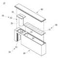
도 2는 본 발명의 바람직한 실시예에 따른 도심 침수심 측정을 위한 연석의 사시도,
도 3은 본 발명의 바람직한 실시예에 따른 도심 침수심 측정을 위한 연석의 분리사시도,
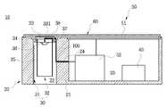
도 4는 본 발명의 바람직한 실시예에 따른 도심 침수심 측정을 위한 연석의 단면도,
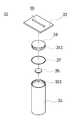
도 5는 본 발명의 바람직한 실시예에 따른 도심 침수심 측정을 위한 연석에서 공기 접촉식 수위계를 보여주는 도면이다.1 is a view for explaining a conventional technique,
FIG. 2 is a perspective view of a curb for measuring the depth of a center of a city according to a preferred embodiment of the present invention,
FIG. 3 is an exploded perspective view of a curb for measuring the depth of a center of a city, according to a preferred embodiment of the present invention;
FIG. 4 is a cross-sectional view of a curb for measuring the depth of a center of a ground according to a preferred embodiment of the present invention;
FIG. 5 is a view showing an air-contact type water level meter in a curb for measuring the depth of a center of a city in accordance with a preferred embodiment of the present invention.
이하, 본 발명의 바람직한 실시예를 첨부된 도면에 의거하여 상세히 설명하며, 도 2 내지 도 5에 있어서 동일한 기능을 수행하는 구성 요소에 대해서는 동일한 참조 번호를 병기한다. 한편, 도면의 도시 및 상세한 설명에 있어서 본 발명의 기술적 특징과 직접적으로 연관되지 않는 요소의 구체적인 기술적 구성 및 작용에 대한 상세한 설명 및 도시는 생략하고, 본 발명과 관련되는 기술적 구성만을 간략하게 도시하거나 설명하였다.Hereinafter, preferred embodiments of the present invention will be described in detail with reference to the accompanying drawings. In FIGS. 2 to 5, the same reference numerals are assigned to components performing the same function. In the drawings and the detailed description, detailed description of specific elements and functions of elements not directly related to the technical features of the present invention will be omitted. .
도 2 내지 도 5를 참고하면, 본 발명의 바람직한 실시예에 따른 도심 침수심 측정을 위한 연석(10)은 본체(20), 수위계(30), 제어부(40), 전원부(50), 덮개(60)를 포함하여 이루어진다.2 to 5, a
본체(20)는 도로의 경계 라인을 구성하는 연석 중 어느 하나인 것으로, 전체 구성요소들이 설치된다.The
본체(20)는 박스형상으로 이루어져 내부에 격벽(21)에 의해 제1공간(22)과 제2공간(23)으로 구분되고, 격벽(21)에는 제1공간(22)과 제2공간(23)과 연통되는 연통공(24)이 형성되어 진다.The
제1공간(22)은 상부와 하부가 개방되고, 전면 일측이 개방되며 개방된 상부, 하부 및 전면 일측은 서로 연통되어 진다. 제2공간(23)은 상부가 개방된다.The upper and lower portions of the
수위계(30)는 본체(20)의 제1공간(22)에 설치되고, 개방된 하부와 전면의 일측을 통해 유입되는 침수심의 수위를 측정하기 위한 것으로, 침수심이 접촉하여 침수심의 수위를 측정하는 접촉식 수위계(31)와, 침수심의 증감에 따른 내부의 공기압을 측정하기 위한 공기 접촉식 수위계(32)를 포함하여 이루어진다.The
접촉식 수위계(31)는 본체(20)의 제1공간(22)의 일측에 설치되어 본체(20)의 하부에서부터의 침수심을 측정하도록 한다.The contact type
공기 접촉식 수위계(32)는 본체(20)의 개방된 하부와 전면의 일측을 통해 유입되는 침수심의 증감에 따른 내부의 공기압을 측정하기 위한 것으로, 제1공간(22)의 개방된 상부와 대응되는 크기로 형성되는 고정판(33)과, 고정판(33)의 하부에 결합되고, 외주면 상에 나사(341)가 형성된 결합구(34)와, 내부공간(351)을 갖고, 상하가 관통되는 원통형상으로 이루어져 결합구(34)와 나사 결합되는 원통관(35)과, 결합구(34)의 하부에 결합되고, 원통관(35)의 내부공간(351)의 공기압을 측정하기 위한 압력센서(36)를 포함하여 이루어진다. 이때, 원통관(35)의 끝단은 본체(20)의 제1공간(22)의 개방된 하부로부터 상측으로 이격되도록 형성된다. 이는 본체(20)의 개방된 전면 일측을 통해 침수심이 용이하게 유입되도록 하기 위함이다.The air-contact type
한편, 고정판(33)은 압력센서(36)와 전원부(50)의 연결을 위한 전선 또는 케이블(100)이 삽입되는 삽입홀(331)이 형성되어 진다. 전선 또는 케이블(100)은 일단이 전원부(50)와 연결되고, 타단은 압력센서(36)와 연결되되, 본체(20)의 격벽(21)의 연통공(24)을 통과하여 고정판(33)의 삽입홀(331)을 통해 서로 간에 연결되도록 한다.The
그리고, 고정판(33)은 본체(20)의 제1공간(22)의 개방된 상부에 착탈이 용이하도록 손잡이(38)가 형성되어 진다.The
이와 같은 구성을 갖는 공기 접촉식 수위계(32)는 침수심이 원통관(35)의 하부를 통해 유입되면 원통관(35)의 내부 공기압은 증가하게 되고, 이를 측정하여 제어부(40)로 전송하게 된다.When the immersion spout is introduced through the lower portion of the
상술한 바와 같이 접촉식 수위계(31)에서 측정한 침수심이 수위와 공기 접촉식 수위계(32)에서 측정한 수위를 상호 검증을 통해 침수심 측정에 대한 신뢰도를 높일 수 있을 것이다.As described above, the reliability of the immersion depth measurement can be increased through mutual verification of the immersion water level measured by the contact type
한편, 공기 접촉식 수위계(32)는 결합구(34)의 외주면 상에 형성되는 나사(341)의 하단부에 형성되고, 상기 원통관(35)과 나사 결합시 기밀을 유지하기 위한 오링(37)을 포함하여 이루어진다.The air contact type
제어부(40)는 본체(20)의 제2공간(23에 설치되고, 수위계(30)에서 측정된 수위를 저장하고, 이를 외부의 서버(미도시)로 전송하는 역할을 한다. 그리고, 공기 접촉식 수위계(32)에서 측정된 원통관(35)의 내부 공기압을 전달받아 이를 침수심으로 변환하여 접촉식 수위계(31)에서 측정된 침수심의 수위를 비교 검증하도록 한다.The
전원부(50)는 본체(20)의 제2공간(23)에 설치되고, 공기 접촉식 수위계(32)로 전원을 공급하기 위한 것으로, 태양전지모듈(51)과 배터리(52)를 포함하는 태양광 전원부 또는 별도의 전원장치로 구성될 수 있을 것이다. 본 발명이 바람직한 실시예에서는 태양광 전원부로 구성한 것으로, 태양광 전원부는 제2공간(23)의 개방된 상부를 덮도록 형성되는 태양전지모듈(51)과 태양전지모듈(51)에 의해 축적된 에너지를 축적하고, 저장하는 배터리(52)를 포함한다. 여기서, 태양광 전원부는 일반적인 태양광을 축적하는 구성을 적용한 것으로 상세한 설명은 생략하기로 한다.The
덮개(60)는 제1공간(22)과 제2공간(23)을 덮도록 형성되는 것으로, 제1공간(22)과 제2공간(23)의 상부를 통해 물이 유입되지 않도록 한다.The
한편, 덮개(60)는 투명한 재질로 이루어져 제1공간(22)과 제2공간(23)을 덮도록 구성된다. 이는 전원부(50)가 태양광 전원부로 구성될 시 태양전지모듈(51)이 태양광을 받도록 하기 위함이다.Meanwhile, the
이상과 같이 본 발명에 따른 도심 침수심 측정을 위한 연석에 의하면, 도로의 경계석을 이루는 연석을 침수심을 측정할 수 있도록 구성함으로써 별도의 구조물을 추가로 설치하지 않아도 도심의 침수심을 측정할 수 있도록 하는 효과가 있다.As described above, according to the curb for measuring the depth of the center of the city according to the present invention, the curb that constitutes the boundary of the road can be measured to measure the flood shims, so that the flood shims of the city can be measured without installing additional structures It is effective.
특히, 본체의 제1공간에 공기 접촉식 수위계를 설치하여 원통관의 내부 공기압을 통해 침수심의 수위를 측정하도록 함으로써 압력센서가 침수심과 접촉되지 않아 압력센서의 부식을 방지하여 유지 관리에 따른 비용을 절감할 수 있는 효과가 있다.In particular, by installing an air contact type water level meter in the first space of the main body, the water level of the immersion shaft is measured through the internal air pressure of the main pipe, so that the pressure sensor does not come into contact with the immersion depth, Can be reduced.
상술한 바와 같은, 본 발명의 바람직한 실시예에 따른 도심 침수심 측정을 위한 연석을 상기한 설명 및 도면에 따라 도시하였지만, 이는 예를 들어 설명한 것에 불과하며 본 발명의 기술적 사상을 벗어나지 않는 범위 내에서 다양한 변화 및 변경이 가능하다는 것을 이 분야의 통상적인 기술자들은 잘 이해할 수 있을 것이다.Although the present invention has been described with reference to the above description and drawings, it is to be understood that the invention is not limited to the disclosed embodiments and that various changes and modifications may be made therein without departing from the spirit and scope of the invention as defined in the appended claims. It will be understood by those of ordinary skill in the art that various changes and modifications may be made.
10 : 도심 침수심 측정을 위한 연석
20 : 본체
21 : 격벽
22 : 제1공간
23 : 제2공간
30 : 수위계
31 : 접촉식 수위계
32 : 공기 접촉식 수위계
33 : 고정판
34 : 결합구
35 : 원통판
36 : 압력센서
37 : 오링
40 : 제어부
50 : 전원부
60 : 덮개10: Curb for measuring the depth of the city center
20:
21:
22: First space
23: Second space
30: Water gauge
31: Contact water gauge
32: Air-contact type water level meter
33: Fixing plate
34:
35: One mail order
36: Pressure sensor
37: O ring
40:
50:
60: Cover
Claims (5)
Translated fromKorean상기 본체(20)의 제1공간(22)에 설치되고, 개방된 하부와 전면의 일측을 통해 유입되는 침수심의 수위를 측정하기 위한 수위계(30)와;
상기 본체(20)의 제2공간(23)에 설치되고, 상기 수위계(30)에서 측정된 수위를 저장하고, 외부의 서버로 전송하기 위한 제어부(40)와;
상기 본체(20)의 제2공간(23)에 설치되고, 상기 제어부(40)와 수위계(30)로 전원을 공급하기 위한 전원부(50)와;
상기 본체(20)의 제1공간(22) 및 제2공간(23)을 덮도록 형성되는 덮개(60)를 포함하되;
상기 수위계(30)는 침수심이 접촉하여 침수심의 수위를 측정하는 접촉식 수위계(31)와;
침수심의 증감에 따른 내부의 공기압을 측정하기 위한 공기 접촉식 수위계(32)를 포함하고,
상기 공기 접촉식 수위계(32)는 상기 제1공간(22)의 개방된 상부와 대응되는 크기로 형성되는 고정판(33)과;
상기 고정판(33)의 하부에 결합되고, 외주면 상에 나사(341)가 형성된 결합구(34)와;
내부공간(351)을 갖고, 상하가 관통되는 원통형상으로 이루어져 상기 결합구(34)와 나사 결합되는 원통관(35)과;
상기 결합구(34)의 하부에 결합되고, 상기 원통관(35)의 내부공간(351)의 공기압을 측정하기 위한 압력센서(36)를 포함하는 것을 특징으로 하는 도심 침수심 측정을 위한 연석.
And a second space (23) separated by the partition wall (21) and having a first space (22) in which upper, lower and front sides are opened and communicated with each other, ) And the second space (23) are separated by a partition (21);
A water gauge 30 installed in the first space 22 of the main body 20 for measuring the water level of the immersion water flowing through one side of the opened lower part and the front part;
A controller 40 installed in the second space 23 of the main body 20 for storing the measured water level in the water level meter 30 and transmitting the measured water level to an external server;
A power supply unit 50 installed in the second space 23 of the main body 20 for supplying power to the control unit 40 and the water gauge 30;
And a cover (60) formed to cover the first space (22) and the second space (23) of the main body (20);
The water gauge (30) includes a contact type water level meter (31) for measuring the water level of the immersion shaft by contacting the immersion shaft;
And an air contact type water level meter (32) for measuring the internal air pressure according to the increase / decrease of immersion depth,
The air contact type water level meter (32) includes a fixing plate (33) formed to have a size corresponding to the open top of the first space (22);
A coupling hole 34 coupled to a lower portion of the fixing plate 33 and having a screw 341 formed on an outer circumferential surface thereof;
A cylindrical tube 35 having an inner space 351 and a cylindrical shape penetrating upper and lower portions and threadedly engaged with the coupling hole 34;
And a pressure sensor (36) coupled to a lower portion of the coupling hole (34) for measuring the air pressure in the internal space (351) of the cylindrical pipe (35).
상기 공기 접촉식 수위계(32)는 상기 결합구(34)의 외주면 상에 형성되는 나사(341)의 하단부에 형성되고, 상기 원통관(35)과 나사 결합시 기밀을 유지하기 위한 오링(37)을 포함하는 것을 특징으로 하는 도심 침수심 측정을 위한 연석.
The method according to claim 1,
The air contact type water level meter 32 is formed at the lower end of a screw 341 formed on the outer circumferential surface of the coupling hole 34 and includes an O-ring 37 for maintaining airtightness when screwed into the cylindrical pipe 35, And a curb for measuring the depth of the center of the ground.
상기 공기 접촉식 수위계(32)의 원통관(35)의 끝단은 상기 본체(20)의 제1공간(22)의 개방된 하부로부터 상측으로 이격되는 것을 특징으로 하는 도심 침수심 측정을 위한 연석.The method according to claim 1,
Wherein an end of the cylindrical pipe (35) of the air-contact type water level meter (32) is spaced upward from an open bottom of the first space (22) of the main body (20).
Priority Applications (4)
| Application Number | Priority Date | Filing Date | Title |
|---|---|---|---|
| KR1020180135293AKR101975751B1 (en) | 2018-11-06 | 2018-11-06 | Curbs for measuring the depth of saliva in urban center |
| JP2019561260AJP6896105B2 (en) | 2018-11-06 | 2018-11-07 | Curb for measuring inundation depth in the city center |
| PCT/KR2018/013462WO2020096082A1 (en) | 2018-11-06 | 2018-11-07 | Curb for measuring flood depth in urban area |
| US16/608,151US11187568B2 (en) | 2018-11-06 | 2018-11-07 | Curb for measuring flood depth in urban area |
Applications Claiming Priority (1)
| Application Number | Priority Date | Filing Date | Title |
|---|---|---|---|
| KR1020180135293AKR101975751B1 (en) | 2018-11-06 | 2018-11-06 | Curbs for measuring the depth of saliva in urban center |
Publications (1)
| Publication Number | Publication Date |
|---|---|
| KR101975751B1true KR101975751B1 (en) | 2019-05-08 |
Family
ID=66580254
Family Applications (1)
| Application Number | Title | Priority Date | Filing Date |
|---|---|---|---|
| KR1020180135293AActiveKR101975751B1 (en) | 2018-11-06 | 2018-11-06 | Curbs for measuring the depth of saliva in urban center |
Country Status (4)
| Country | Link |
|---|---|
| US (1) | US11187568B2 (en) |
| JP (1) | JP6896105B2 (en) |
| KR (1) | KR101975751B1 (en) |
| WO (1) | WO2020096082A1 (en) |
Families Citing this family (5)
| Publication number | Priority date | Publication date | Assignee | Title |
|---|---|---|---|---|
| US11512995B2 (en)* | 2019-10-10 | 2022-11-29 | Intellisense Systems, Inc. | Flood sensing system and method |
| CN114577302B (en)* | 2022-03-02 | 2022-11-29 | 武汉新烽光电股份有限公司 | Lightning protection anti-interference bubble type water level gauge |
| CN115307700A (en) | 2022-09-13 | 2022-11-08 | 深圳市科敏传感器有限公司 | Multifunctional water level sensor for monitoring accumulated water on road surface |
| GB2634536A (en)* | 2023-10-12 | 2025-04-16 | Tack One Pte Ltd | Water level measuring device and method for measuring the water level of a water container |
| KR102837135B1 (en)* | 2024-10-07 | 2025-07-22 | (주)드림엔지니어링 | Installation structure of water and sewage buried pipe location check device |
Citations (3)
| Publication number | Priority date | Publication date | Assignee | Title |
|---|---|---|---|---|
| KR101092093B1 (en) | 2010-04-29 | 2011-12-13 | 주식회사 케이티 | Flood detection device and street light |
| KR101178843B1 (en)* | 2011-12-22 | 2012-09-03 | 온라인인스트루먼트 주식회사 | Road Boundary Stone Being Capable of Managing Rainfall |
| KR101202841B1 (en)* | 2010-06-15 | 2012-11-20 | 주식회사 디앤샤인 | System and Method for Monitoring Flooding of Road |
Family Cites Families (27)
| Publication number | Priority date | Publication date | Assignee | Title |
|---|---|---|---|---|
| KR100202841B1 (en)* | 1995-09-30 | 1999-06-15 | 전주범 | Range lighting device |
| US6142017A (en)* | 1999-02-10 | 2000-11-07 | Glassey; Eugene A. | Hydrostatic pressure equalizer apparatus and system |
| JP2002069913A (en)* | 2000-06-12 | 2002-03-08 | Tobata Tekko Kk | Road side facility and road side member used therefor |
| JP3632125B2 (en)* | 2000-10-30 | 2005-03-23 | 株式会社キクテック | Curb block light emitting device |
| JP2005120045A (en)* | 2003-10-17 | 2005-05-12 | Dai Ichi Kogyo Seiyaku Co Ltd | Cosmetic composition for hair |
| KR100775016B1 (en)* | 2004-08-24 | 2007-11-09 | 주식회사 메디슨 | Method and apparatus for providing improved help in ultrasonic equipment |
| US7902838B2 (en)* | 2004-11-17 | 2011-03-08 | Continental Automotive Systems Us, Inc. | Sensor device for determining a fluid property |
| KR20100092093A (en)* | 2009-02-12 | 2010-08-20 | 주식회사 제로팩 | Sticker type check valve for vacuum bag and vacuum bag sealing set using the same |
| US20100263458A1 (en)* | 2009-04-20 | 2010-10-21 | Itt Manufacturing Enterprises, Inc. | Self contained inline field effect fluid detection |
| US20110056289A1 (en)* | 2009-09-07 | 2011-03-10 | Senghaas Karl A | Floatless Rain Gauge |
| KR101019817B1 (en) | 2009-10-01 | 2011-03-04 | 이정대 | Road boundary stone with notice function |
| WO2012106053A2 (en)* | 2011-02-03 | 2012-08-09 | Anderson Instrument Company Inc. | Sensor assembly for hygenic material processing systems |
| US8786453B2 (en)* | 2012-08-15 | 2014-07-22 | Belinda J. Walbert | Alert system for detecting rising water levels |
| US9978246B2 (en)* | 2012-08-15 | 2018-05-22 | Belinda J. Walbert | Alert system for detecting rising water levels |
| US9576463B2 (en)* | 2012-08-15 | 2017-02-21 | Belinda J. Walbert | Alert system for detecting rising water levels |
| WO2016042456A2 (en)* | 2014-09-15 | 2016-03-24 | Eltek S.P.A. | Sensor for detecting the level of a medium |
| JP6460118B2 (en)* | 2014-11-21 | 2019-01-30 | 富士通株式会社 | Water volume measuring device and water volume monitoring system |
| KR101673768B1 (en) | 2015-05-11 | 2016-11-07 | 김면갑 | Immersion detection alarms and alarm systems |
| KR101775016B1 (en) | 2016-01-22 | 2017-09-05 | 주식회사 디앤샤인 | System for Monitoring Flooding of Road With Variable Sensor |
| JP2017181054A (en)* | 2016-03-28 | 2017-10-05 | 日鐵住金建材株式会社 | Water level measurement device |
| TWI577966B (en)* | 2016-04-11 | 2017-04-11 | 財團法人國家實驗研究院 | Composite hydrological monitoring system |
| ITUA20163239A1 (en)* | 2016-04-18 | 2017-10-18 | Eltek Spa | DEVICE FOR DETECTION OF THE LEVEL OF A MEDIA |
| US20170352266A1 (en)* | 2016-06-02 | 2017-12-07 | Kyle Lynn Watson | Advanced flood gauge |
| JP2019031774A (en)* | 2017-08-04 | 2019-02-28 | 高久産業株式会社 | Display pole |
| GB2578564A (en)* | 2018-02-07 | 2020-05-20 | Floodflash Ltd | Device and method for sensing the level of naturally-occurring water, and method for installation of such a device |
| US10996095B2 (en)* | 2018-07-24 | 2021-05-04 | Sensata Technologies, Inc. | Dielectric-constant-insensitive fluid level sensor |
| US11519772B2 (en)* | 2018-08-25 | 2022-12-06 | Evigia Systems, Inc. | Liquid pressure and level sensor systems and sensors, methods, and applications therefor |
- 2018
- 2018-11-06KRKR1020180135293Apatent/KR101975751B1/enactiveActive
- 2018-11-07WOPCT/KR2018/013462patent/WO2020096082A1/ennot_activeCeased
- 2018-11-07USUS16/608,151patent/US11187568B2/enactiveActive
- 2018-11-07JPJP2019561260Apatent/JP6896105B2/enactiveActive
Patent Citations (3)
| Publication number | Priority date | Publication date | Assignee | Title |
|---|---|---|---|---|
| KR101092093B1 (en) | 2010-04-29 | 2011-12-13 | 주식회사 케이티 | Flood detection device and street light |
| KR101202841B1 (en)* | 2010-06-15 | 2012-11-20 | 주식회사 디앤샤인 | System and Method for Monitoring Flooding of Road |
| KR101178843B1 (en)* | 2011-12-22 | 2012-09-03 | 온라인인스트루먼트 주식회사 | Road Boundary Stone Being Capable of Managing Rainfall |
Also Published As
| Publication number | Publication date |
|---|---|
| JP6896105B2 (en) | 2021-06-30 |
| WO2020096082A1 (en) | 2020-05-14 |
| JP2021509454A (en) | 2021-03-25 |
| US11187568B2 (en) | 2021-11-30 |
| US20210255022A1 (en) | 2021-08-19 |
Similar Documents
| Publication | Publication Date | Title |
|---|---|---|
| KR101975751B1 (en) | Curbs for measuring the depth of saliva in urban center | |
| KR101092093B1 (en) | Flood detection device and street light | |
| KR101365688B1 (en) | System for alarming a flooded road using a flooded road sensing device | |
| KR102227149B1 (en) | Flood-warning device | |
| US20190197892A1 (en) | Flood warning system and process for detecting a level of water in a waterway | |
| KR101345186B1 (en) | System for monitoring flooding of road and its method | |
| KR101671383B1 (en) | Inundation notification system based on Smart Bar | |
| CN107655545B (en) | Ground pile type water level monitoring device and water level monitoring method | |
| KR101775016B1 (en) | System for Monitoring Flooding of Road With Variable Sensor | |
| CN104864935A (en) | System and method for real-time monitoring of city drainage pipelines | |
| JP2017181054A (en) | Water level measurement device | |
| KR20190074682A (en) | Sensor module for sensing immersion and water level | |
| KR101178843B1 (en) | Road Boundary Stone Being Capable of Managing Rainfall | |
| CN109029634A (en) | A kind of excess surface water depth-measuring system and method | |
| KR102706329B1 (en) | Flooding information system using bollard-type flooding detection device | |
| KR101192404B1 (en) | Protecting Riverhead And Nonpoint Pollution Source Reduction Controlling System Using Green Dam | |
| CN207231582U (en) | Ponding on-line monitoring system under a kind of bridge based on cloud platform | |
| JP6503825B2 (en) | Photovoltaic power generation device, sensing device and information processing system | |
| CN205899813U (en) | Intelligent water flooding prevention safety system for highway bridge opening road section | |
| KR20220165930A (en) | The danger warning type manhole cover | |
| CN208458841U (en) | A kind of bridges and culverts depth of accumulated water measuring system | |
| US20200363392A1 (en) | Smart porous concrete slab | |
| KR102547585B1 (en) | Inundation depth measurement device | |
| CN107356305A (en) | A kind of municipal sewerage engineering management method | |
| KR102690805B1 (en) | Manhole cover |
Legal Events
| Date | Code | Title | Description |
|---|---|---|---|
| PA0109 | Patent application | Patent event code:PA01091R01D Comment text:Patent Application Patent event date:20181106 | |
| PA0201 | Request for examination | ||
| PA0302 | Request for accelerated examination | Patent event date:20181115 Patent event code:PA03022R01D Comment text:Request for Accelerated Examination Patent event date:20181106 Patent event code:PA03021R01I Comment text:Patent Application | |
| PE0902 | Notice of grounds for rejection | Comment text:Notification of reason for refusal Patent event date:20190108 Patent event code:PE09021S01D | |
| E701 | Decision to grant or registration of patent right | ||
| PE0701 | Decision of registration | Patent event code:PE07011S01D Comment text:Decision to Grant Registration Patent event date:20190327 | |
| GRNT | Written decision to grant | ||
| PR0702 | Registration of establishment of national patent | Patent event code:PR07021E01D Comment text:Registration of Establishment of National Patent Patent event date:20190430 | |
| PR1002 | Payment of registration fee | Payment date:20190430 End annual number:20 Start annual number:1 | |
| PG1601 | Publication of registration |