KR101974037B1 - Hinge unit and arm-rest having the hinge unit - Google Patents
Hinge unit and arm-rest having the hinge unitDownload PDFInfo
- Publication number
- KR101974037B1 KR101974037B1KR1020180146399AKR20180146399AKR101974037B1KR 101974037 B1KR101974037 B1KR 101974037B1KR 1020180146399 AKR1020180146399 AKR 1020180146399AKR 20180146399 AKR20180146399 AKR 20180146399AKR 101974037 B1KR101974037 B1KR 101974037B1
- Authority
- KR
- South Korea
- Prior art keywords
- shaft
- casing
- main
- sub
- axial direction
- Prior art date
- Legal status (The legal status is an assumption and is not a legal conclusion. Google has not performed a legal analysis and makes no representation as to the accuracy of the status listed.)
- Active
Links
Images


Classifications
- A—HUMAN NECESSITIES
- A47—FURNITURE; DOMESTIC ARTICLES OR APPLIANCES; COFFEE MILLS; SPICE MILLS; SUCTION CLEANERS IN GENERAL
- A47C—CHAIRS; SOFAS; BEDS
- A47C1/00—Chairs adapted for special purposes
- A47C1/02—Reclining or easy chairs
- A47C1/022—Reclining or easy chairs having independently-adjustable supporting parts
- A47C1/03—Reclining or easy chairs having independently-adjustable supporting parts the parts being arm-rests
- A47C1/0303—Reclining or easy chairs having independently-adjustable supporting parts the parts being arm-rests adjustable rectilinearly in vertical direction
- A—HUMAN NECESSITIES
- A47—FURNITURE; DOMESTIC ARTICLES OR APPLIANCES; COFFEE MILLS; SPICE MILLS; SUCTION CLEANERS IN GENERAL
- A47C—CHAIRS; SOFAS; BEDS
- A47C7/00—Parts, details, or accessories of chairs or stools
- A47C7/54—Supports for the arms
- A47C7/541—Supports for the arms of adjustable type
- A—HUMAN NECESSITIES
- A47—FURNITURE; DOMESTIC ARTICLES OR APPLIANCES; COFFEE MILLS; SPICE MILLS; SUCTION CLEANERS IN GENERAL
- A47B—TABLES; DESKS; OFFICE FURNITURE; CABINETS; DRAWERS; GENERAL DETAILS OF FURNITURE
- A47B2220/00—General furniture construction, e.g. fittings
- A47B2220/0061—Accessories
- A47B2220/0069—Hinges
- A47B2220/0072—Hinges for furniture
Landscapes
- Health & Medical Sciences (AREA)
- Dentistry (AREA)
- General Health & Medical Sciences (AREA)
- Seats For Vehicles (AREA)
Abstract
Translated fromKorean
Description
Translated fromKorean본 발명은 위치설정유닛 및 이를 구비한 의자용 팔걸이에 관한 것으로서, 더욱 상세하게는 조인트빔에 암지지빔을 힌지 연결하고 샤프트를 조인트빔과 암지지빔의 힌지 부위에 연결한 상태로 외부 조작에 의해 샤프트의 축 방향 이동을 단속하면서 이에 연동하여 조인트빔에 대한 암지지빔의 기울기를 조절 가능하도록 함으로써, 착석자의 신체조건이나 사용 상태에 따라 암지지빔의 위치를 다양하게 가변시킬 수 있어, 사용상 편의성을 증대하기 위한 위치설정유닛 및 이를 구비한 의자용 팔걸이에 관한 것이다.The present invention relates to a position setting unit and an armrest for a chair having the same, and more particularly, to a position setting unit and an armrest for a chair having the same, The position of the arm support beam can be varied in various ways according to the body condition and the use state of the seated person by controlling the inclination of the arm support beam with respect to the joint beam by interlocking with the movement of the shaft in the axial direction, A position setting unit for increasing convenience, and an armrest for a chair having the same.
일반적으로, 사용자가 의자에 착석한 상태에서 업무를 수행하거나, 교육을 받을 경우에는 좌판의 일측에 엉덩이가 치우치도록 착석하게 된다.Generally, when a user performs a task while being seated in a chair, or is educated, the user is seated in such a way that his butt is offset at one side of the seat.
통상 의자는 등받이판과 좌판이 소정의 각도를 이루도록 결합되고, 좌판의 하부에는 좌판을 안정적으로 지지할 수 있도록 한 다리가 결합되는 구조로 이루어진다.The conventional chair has a structure in which a backrest plate and a seat plate are coupled to each other at a predetermined angle, and a leg is coupled to a lower portion of the seat plate so as to stably support the seat plate.
좌판 및 등받이판은 스폰지 등의 쿠션부재가 내장되어 사용자의 착석시 탄력에 의해 편안한 착석감을 줄 수 있도록 형성되어 있으며, 또한, 사용자가 스트레칭을 하거나 누울 수 있도록 등을 뒤로 젖히면 좌판에 대해 등받이판이 뒤로 틸팅되는 구조이다.The seat back and the backrest plate are formed to have a cushion member such as a sponge so as to provide a comfortable sitting feeling due to the elasticity of the seat when the user is seated. Further, when the back is turned back so that the user can stretch or lie, Tilting structure.
이러한 의자들은 좌판에 대해 등받이판이 틸팅 가능하도록 구성되어 사용자가 등을 기댄 상태에서 뒤로 젖힐 경우에도 사용자의 등을 지지할 수 있다.These chairs are configured to be able to tilt the backrest plate relative to the seat so that the user can support the back of the user even when the user is leaning back from the back.
특히, 국내등록실용신안공보 제20-0340408호에는 '의자팔걸이용 높이조절구'가 제안된 바 있다.Particularly, the Korean Registered Utility Model No. 20-0340408 has proposed a height adjuster for a chair armrest.
상기한 기술구성은 본 발명의 이해를 돕기 위한 배경기술로서, 본 발명이 속하는 기술분야에서 널리 알려진 종래기술을 의미하는 것은 아니다.The technical structure described above is a background technique for assisting the understanding of the present invention, and does not mean the prior art widely known in the technical field to which the present invention belongs.
기존의 의자는 단순히 팔걸이의 높낮이를 조절하거나 회전시키는 것으로서, 팔걸이만 사용하는 경우에는 허리를 굽히는 등 올바른 자세를 유도하기 어려우며, 다양한 신체조건을 갖는 다수의 착석자를 모두 만족시키기에는 한계가 있다.Conventional chairs simply adjust or rotate the height of the armrest. When using only the armrest, it is difficult to induce the correct posture such as bending the waist, and there is a limit to satisfying all the seated persons having various physical conditions.
따라서, 이를 개선할 필요성이 요청된다.Therefore, there is a need to improve this.
본 발명은 상기와 같은 문제점들을 개선하기 위하여 안출된 것으로서, 조인트빔에 암지지빔을 힌지 연결하고 샤프트를 조인트빔과 암지지빔의 힌지 부위에 연결한 상태로 레버의 조작 여부를 통해 샤프트의 축 방향 이동을 단속하면서 이에 연동하여 조인트빔에 대한 암지지빔의 기울기를 조절 가능하도록 함으로써, 착석자의 신체조건이나 사용 상태에 따라 암지지빔의 위치를 다양하게 가변시킬 수 있어, 사용상 편의성을 증대하고자 하는 위치설정유닛 및 이를 구비한 의자용 팔걸이를 제공하는데 그 목적이 있다.SUMMARY OF THE INVENTION The present invention has been conceived to solve the problems as described above, and it is an object of the present invention to provide a joint support apparatus, a hinge support apparatus, It is possible to vary the position of the arm support beam according to the body condition or the use state of the seated person by making the inclination of the arm support beam with respect to the joint beam adjustable in conjunction with interlocking the direction movement, And an armrest for a chair having the same.
본 발명에 따른 위치설정유닛은: 케이싱; 상기 케이싱에 대해 축 방향으로 양방향 이동 가능하도록, 상기 케이싱에 관통되게 삽입되는 샤프트; 및 상기 케이싱에 대해 상기 샤프트의 축 방향 이동을 허용하거나, 이동을 방지하는 로킹부를 포함한다.A positioning unit according to the present invention comprises: a casing; A shaft inserted into the casing so as to be movable in the axial direction in both directions with respect to the casing; And a locking portion for allowing axial movement of the shaft with respect to the casing, or preventing movement.
상기 로킹부는, 상기 샤프트를 축 삽입하기 위해 메인삽입구를 일측에 형성하고, 일측 가장자리를 상기 케이싱에 위치 고정하도록 연결하여, 상기 샤프트의 축 방향에 대한 기울어짐 정도에 따라 상기 메인삽입구의 내측면이 상기 샤프트의 둘레면을 가압하는 정도를 달리함으로써, 상기 샤프트의 축 방향 이동을 단속 안내하는 메인로커; 상기 케이싱의 내부 타측에 탄성 지지되는 탄성지지블록; 상기 탄성지지블록에서 상기 케이싱의 일측 외부로 돌출되도록 연장되는 푸셔; 및 상기 메인삽입구의 내측면이 상기 샤프트의 둘레면을 가압함으로써 상기 샤프트의 축 방향 이동을 방지하기 위해 상기 메인로커가 초기에 상기 샤프트의 축 방향에 대해 경사진 상태를 유지하도록 상기 메인로커의 타측을 지지하고, 외력에 의해 상기 푸셔와 함께 이동되는 지지리브를 포함한다.The locking portion is formed with a main insertion port at one side for shaft insertion of the shaft and is connected to one end of the casing so as to be fixed to the casing so that the inner side surface of the main insertion port A main locker for guiding intermittent movement of the shaft in the axial direction by varying a degree of pressing the circumferential surface of the shaft; An elastic supporting block elastically supported on the other side of the casing; A pusher extending from the elastic supporting block so as to protrude to one side of the casing; And an inner side surface of the main insertion port is pressed against the circumferential surface of the shaft to prevent axial movement of the shaft so that the main locker is initially tilted with respect to the axial direction of the shaft, And a support rib which is moved together with the pusher by an external force.
상기 로킹부는, 상기 샤프트의 축 방향으로 상기 메인로커와 설정거리만큼 유격되고, 상기 샤프트를 축 삽입하기 위해 서브삽입구를 일측에 형성하며, 일측 가장자리를 상기 케이싱에 위치 고정하도록 연결하여, 상기 샤프트의 축 방향에 대한 기울어짐 정도에 따라 상기 메인삽입구의 내측면이 상기 샤프트의 둘레면을 가압하는 힘을 증가시키는 서브로커; 및 상기 케이싱에 회전 가능하게 구비되고, 상기 푸셔에 연동되어 편심 회전됨으로써 외력에 의해 상기 푸셔가 작동시 상기 서브로커와 이격됨으로써, 상기 샤프트에 대한 상기 서브로커의 구속력을 해제 또는 저감시키는 편심블록을 포함한다.Wherein the locking portion is spaced apart from the main locker by a predetermined distance in the axial direction of the shaft, and a sub-insertion opening is formed at one side for shaft insertion of the shaft, and a side edge is connected to the casing to fix the position, A throat broker for increasing an urging force of an inner surface of the main insertion port against a circumferential surface of the shaft according to a degree of inclination with respect to an axial direction; And an eccentric block which is rotatably provided on the casing and is eccentrically rotated by interlocking with the pusher so as to be separated from the sub broker when the pusher is operated by an external force, thereby releasing or reducing the binding force of the sub broker with respect to the shaft .
상기 탄성지지블록은, 당겨지는 외력에 의해, 상기 푸셔가 누르는 방향으로 탄성적으로 이동되는 것을 특징으로 한다.And the elastic supporting block is elastically moved in a direction in which the pusher is pressed by an external force to be pulled.
상기 메인로커와 상기 서브로커는 상기 케이싱에 구비된 서포팅블록에 각각의 일측이 접하여 지지되고, 상기 메인로커는 상기 케이싱의 내측에 탄성 지지되는 메인탄성부재에 의해 상기 서포팅블록 측으로 가압되며, 상기 서브로커는 상기 케이싱의 내측에 탄성 지지되는 서브탄성부재에 의해 상기 서포팅블록 측으로 가압되는 것을 특징으로 한다.Wherein the main locker and the sub broker are supported on one side of a supporting block provided on the casing and the main locker is pressed toward the supporting block by a main elastic member elastically supported inside the casing, And the broker is pressed toward the supporting block by a sub elastic member elastically supported on the inside of the casing.
본 발명에 따른 의자용 팔걸이는: 상측에 암패드를 연결하고, 하측이 조인트빔에 회동 가능하도록 힌지 연결되는 암지지빔; 상기 암지지빔의 내부에 고정되어, 상기 조인트빔에 대한 상기 암지지빔의 각도 조절을 허용하거나 위치를 고정하는 위치설정유닛; 및 상기 암지지빔의 각도 조절을 위해, 상기 위치설정유닛에 외력을 가하도록 조작하는 조작부를 포함한다.An armrest for a chair according to the present invention comprises: an arm supporting beam connecting an arm pad on an upper side and hinged on a lower side of the joint beam so as to be rotatable; A positioning unit fixed within the arm support beam to allow or adjust the position of the arm support beam with respect to the joint beam; And an operation unit for operating the position setting unit to apply an external force to adjust the angle of the arm support beam.
상기 위치설정유닛은, 상기 암지지빔 내측에 고정 장착되는 케이싱; 상기 케이싱에 대해 축 방향으로 양방향 이동 가능하도록 상기 케이싱에 관통되게 삽입되고, 상기 암지지빔과 상기 조인트빔의 힌지 연결부위에 힌지 연결되는 샤프트; 및 상기 케이싱에 대해 상기 샤프트의 축 방향 이동을 허용하거나, 이동을 방지하는 로킹부를 포함한다.The position setting unit includes: a casing fixedly mounted inside the arm supporting beam; A shaft inserted through the casing so as to be movable in both directions in the axial direction with respect to the casing and hinged to the hinge connection portion of the arm support beam and the joint beam; And a locking portion for allowing axial movement of the shaft with respect to the casing, or preventing movement.
상기 로킹부는, 상기 샤프트를 축 삽입하기 위해 메인삽입구를 일측에 형성하고, 일측 가장자리를 상기 케이싱에 위치 고정하도록 연결하여, 상기 샤프트의 축 방향에 대한 기울어짐 정도에 따라 상기 메인삽입구의 내측면이 상기 샤프트의 둘레면을 가압하는 정도를 달리함으로써, 상기 샤프트의 축 방향 이동을 단속 안내하는 메인로커; 상기 케이싱의 내부 타측에 탄성 지지되는 탄성지지블록; 상기 메인삽입구의 내측면이 상기 샤프트의 둘레면을 가압함으로써 상기 샤프트의 축 방향 이동을 방지하기 위해 상기 메인로커가 초기에 상기 샤프트의 축 방향에 대해 경사진 상태를 유지하도록 상기 메인로커의 타측을 지지하고, 외력에 의해 이동되는 지지리브; 상기 샤프트의 축 방향으로 상기 메인로커와 설정거리만큼 유격되고, 상기 샤프트를 축 삽입하기 위해 서브삽입구를 일측에 형성하며, 일측 가장자리를 상기 케이싱에 위치 고정하도록 연결하여, 상기 샤프트의 축 방향에 대한 기울어짐 정도에 따라 상기 메인삽입구의 내측면이 상기 샤프트의 둘레면을 가압하는 힘을 증가시키는 서브로커; 및 상기 케이싱에 회전 가능하게 구비되고, 편심 회전됨으로써 외력에 의해 상기 서브로커와 이격됨으로써, 상기 샤프트에 대한 상기 서브로커의 구속력을 해제 또는 저감시키는 편심블록을 포함한다.The locking portion is formed with a main insertion port at one side for shaft insertion of the shaft and is connected to one end of the casing so as to be fixed to the casing so that the inner side surface of the main insertion port A main locker for guiding intermittent movement of the shaft in the axial direction by varying a degree of pressing the circumferential surface of the shaft; An elastic supporting block elastically supported on the other side of the casing; The inner side surface of the main insertion port presses the circumferential surface of the shaft so that the main rocker is initially tilted with respect to the axial direction of the shaft so as to prevent the shaft from moving in the axial direction, A supporting rib which supports and is moved by an external force; A sub-insertion hole is formed at one side of the shaft for axial insertion of the shaft, and a side edge of the sub-insertion hole is connected to the casing so as to fix the shaft, A sub broker for increasing an urging force of the inner surface of the main insertion port against the circumferential surface of the shaft depending on a degree of inclination; And an eccentric block that is rotatably provided in the casing and is eccentrically rotated to be separated from the sub broker by an external force, thereby releasing or reducing the binding force of the sub broker with respect to the shaft.
상기 조작부는, 상기 탄성지지블록에 연결되는 와이어; 및 상기 와이어를 연결하고, 상기 암지지빔 또는 상기 암패드에 회동 가능하게 연결되어, 회동시 상기 와이어를 통해 상기 탄성지지블록을 탄성적으로 당김으로써 상기 샤프트의 축 방향 이동을 허용함에 따라 상기 암지지빔의 각도 조절이 가능한 레버를 포함한다.Wherein the operating portion includes: a wire connected to the elastic supporting block; And a wire connecting the wire and pivotally connected to the arm support beam or the arm pad to allow axial movement of the shaft by elastically pulling the elastic support block through the wire upon rotation, And a lever capable of adjusting the angle of the support beam.
이상에서 설명한 바와 같이, 본 발명에 따른 위치설정유닛 및 이를 구비한 의자용 팔걸이는 종래 기술과 달리 조인트빔에 암지지빔을 힌지 연결하고 샤프트를 조인트빔과 암지지빔의 힌지 부위에 연결한 상태로 레버의 조작 여부를 통해 샤프트의 축 방향 이동을 단속하면서 이에 연동하여 조인트빔에 대한 암지지빔의 기울기를 조절 가능하도록 함으로써, 착석자의 신체조건이나 사용 상태에 따라 암지지빔의 위치를 다양하게 가변시킬 수 있어, 사용상 편의성을 증대할 수 있다.As described above, the position setting unit and the armrest for a chair according to the present invention are different from the conventional art in that the arm supporting beam is hinged to the joint beam and the shaft is connected to the hinge portion of the joint beam and the arm supporting beam It is possible to control the inclination of the arm support beam with respect to the joint beam by interlocking with the movement of the shaft in the axial direction through the operation of the lever by operating the lever so that the position of the arm support beam can be varied So that the convenience of use can be increased.
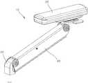
도 1은 본 발명의 일 실시예에 따른 위치설정유닛을 구비한 의자용 팔걸이의 사시도이다.
도 2는 본 발명의 일 실시예에 따른 의자용 팔걸이의 분해 사시도이다.
도 3은 본 발명의 일 실시예에 따른 위치설정유닛의 분해 사시도이다.
도 4는 본 발명의 일 실시예에 따른 의자용 팔걸이의 단면도이다.
도 5는 본 발명의 일 실시예에 따른 의자용 팔걸이의 요부 확대 단면도이다.
도 6은 본 발명의 일 실시예에 따른 의자용 팔걸이의 기울기 조절 상태를 보인 작동도이다.
도 7은 본 발명의 일 실시예에 따른 의자용 팔걸이의 기울기 조절 상태에 따라 암지지빔이 기울기 조절되는 작동 상태도이다.1 is a perspective view of an armrest for a chair having a position setting unit according to an embodiment of the present invention.
2 is an exploded perspective view of a chair armrest according to an embodiment of the present invention.
3 is an exploded perspective view of a positioning unit according to an embodiment of the present invention.
4 is a cross-sectional view of an armrest for a chair according to an embodiment of the present invention.
5 is an enlarged cross-sectional view of an essential portion of an armrest for a chair according to an embodiment of the present invention.
FIG. 6 is an operation diagram showing a tilt adjustment state of an armrest for a chair according to an embodiment of the present invention.
FIG. 7 is a view illustrating an operation state in which an arm supporting beam is inclined according to a tilt adjustment state of an armrest for a chair according to an embodiment of the present invention.
이하, 첨부된 도면들을 참조하여 본 발명에 따른 위치설정유닛 및 이를 구비한 의자용 팔걸이의 실시예를 설명한다. 이 과정에서 도면에 도시된 선들의 두께나 구성요소의 크기 등은 설명의 명료성과 편의상 과장되게 도시되어 있을 수 있다. 또한, 후술되는 용어들은 본 발명에서의 기능을 고려하여 정의된 용어들로서 이는 사용자, 운용자의 의도 또는 관례에 따라 달라질 수 있다. 그러므로 이러한 용어들에 대한 정의는 본 명세서 전반에 걸친 내용을 토대로 내려져야 할 것이다.DESCRIPTION OF THE PREFERRED EMBODIMENTS Hereinafter, embodiments of a positioning unit and an armrest for a chair having the positioning unit according to the present invention will be described with reference to the accompanying drawings. In this process, the thicknesses of the lines and the sizes of the components shown in the drawings may be exaggerated for clarity and convenience of explanation. In addition, the terms described below are defined in consideration of the functions of the present invention, which may vary depending on the intention or custom of the user, the operator. Therefore, definitions of these terms should be made based on the contents throughout this specification.
도 1은 본 발명의 일 실시예에 따른 위치설정유닛을 구비한 의자용 팔걸이의 사시도이고, 도 2는 본 발명의 일 실시예에 따른 의자용 팔걸이의 분해 사시도이며, 도 3은 본 발명의 일 실시예에 따른 위치설정유닛의 분해 사시도이다.FIG. 1 is a perspective view of an armrest for a chair having a position setting unit according to an embodiment of the present invention, FIG. 2 is an exploded perspective view of a chair armrest according to an embodiment of the present invention, Fig. 7 is an exploded perspective view of the positioning unit according to the embodiment.
도 4는 본 발명의 일 실시예에 따른 의자용 팔걸이의 단면도이고, 도 5는 본 발명의 일 실시예에 따른 의자용 팔걸이의 요부 확대 단면도이다.FIG. 4 is a sectional view of an armrest for a chair according to an embodiment of the present invention, and FIG. 5 is an enlarged cross-sectional view of an essential part of an armrest for a chair according to an embodiment of the present invention.
도 6은 본 발명의 일 실시예에 따른 의자용 팔걸이의 기울기 조절 상태를 보인 작동도이고, 도 7은 본 발명의 일 실시예에 따른 의자용 팔걸이의 기울기 조절 상태에 따라 암지지빔이 기울기 조절되는 작동 상태도이다.FIG. 6 is an operational view showing a tilt adjustment state of an armrest for a chair according to an embodiment of the present invention. FIG. 7 is a view illustrating a tilt adjustment state of the arm support beam according to the tilt adjustment state of the armrest for a chair according to an embodiment of the present invention. Fig.
도 1 내지 도 7을 참조하면, 본 발명의 일 실시예에 따른 의자용 팔걸이(10)는 암지지빔(40), 위치설정유닛(100) 및 조작부(200)를 포함한다.1 to 7, an
암지지빔(40)은 의자의 조인트빔(30)에 연결된다. 이때, 조인트빔(30)은 프레임 또는 좌판(도시하지 않음)에 고정되게 연결되거나 회동 가능하게 연결된다.The arm support beam (40) is connected to the joint beam (30) of the chair. At this time, the
그리고, 암지지빔(40)은 조인트빔(30)에 상하 방향으로 회동 가능하게 힌지 연결된다. 아울러, 암지지빔(40)은 상측에 암패드(20)를 연결한다. 이때, 조인트빔(30)과 암패드(20)는 다양한 형상으로 변형 가능하다.The
특히, 암지지빔(40)이 조인트빔(30)에 대해 상하 방향으로 회동 가능함에 따라, 의자에 착석하는 착석자가 신체 사이즈나 상태에 따라 암지지빔(40)의 높이를 조절 가능함으로써, 착석 편의성이 증대된다.Particularly, since the
한편, 위치설정유닛(100)은 암지지빔(40)의 내부에 고정되어, 조인트빔(30)에 대한 암지지빔(40)의 각도 조절을 허용하거나 위치를 고정하는 역할을 한다.On the other hand, the
그리고, 조작부(200)는 암지지빔(40)의 각도 조절을 위해, 위치설정유닛(100)에 외력을 가하도록 조작하는 역할을 한다.The
상세히, 위치설정유닛(100)은 케이싱(110), 샤프트(120) 및 로킹부(130)를 포함한다.In detail, the
케이싱(110)은 암지지빔(40)의 내측에 고정 장착된다. 물론, 케이싱(110)은 다양한 형상으로 변형 가능하고, 다양한 방식으로 암지지빔(40)의 내측에 고정 설치될 수 있다.The
샤프트(120)는 케이싱(110)에 대해 축 방향으로 양방향 이동 가능하도록, 케이싱(110)에 관통되게 축 삽입된다. 이때, 샤프트(120)는 암지지빔(40)의 축 방향을 따라 왕복 이동 가능하도록 케이싱(110)에 삽입된다. 그리고, 샤프트(120)는 일측(하측)이 암지지빔(40)과 조인트빔(30)의 힌지 연결부위에 힌지 연결된다. 그래서, 케이싱(110)이 암지지빔(40)에 고정된 상태에서, 암지지빔(40)이 조인트빔(30)에 대해 회동되며 기울기 조절될 경우, 케이싱(110)은 샤프트(120)의 축 방향을 따라 일방향으로 직선 이동될 수도 있고, 타측으로 직선 이동될 수도 있다.The
물론, 샤프트(120)가 케이싱(110)에 대해 축 방향으로 왕복 이동 가능할 수도 있다.Of course, the
또한, 로킹부(130)는 케이싱(110)에 대해 샤프트(120)의 축 방향 이동을 허용하거나, 이동을 방지하는 역할을 한다. 이로써, 암지지빔(40)은 위치설정유닛(100)의 샤프트(120)의 축 방향 이동에 의해 높낮이 조절된 후 로킹부(130)에 의해 높낮이 조절된 상태를 유지하게 된다.In addition, the
한편, 로킹부(130)는 메인로커(131), 탄성지지블록(132), 푸셔(133), 지지리브(134), 서브로커(135) 및 편심블록(136)을 포함한다.The
메인로커(131)는 샤프트(120)를 축 삽입하기 위해 메인삽입구(131a)를 축 방향을 따라 일측에 형성한다. 그리고, 메인로커(131)는 일측 가장자리를 케이싱(110)에 위치 고정한다. 이를 위해, 케이싱(110)은 내측면에 메인홈부(114)를 형성하고, 메인로커(131)는 일측 가장자리를 메인홈부(114)에 삽입한다. 특히, 메인삽입구(131a)에 삽입된 샤프트(120)가 케이싱(110)의 양측으로 노출되도록 케이싱(110)에 지지됨으로써, 메인로커(131)는 일측이 메인홈부(114)에 삽입된 상태를 유지한 채 일측으로 기준으로 소정 회동 가능하게 된다.The
그리고, 메인로커(131)는 샤프트(120)의 축 방향에 대한 기울어짐 정도에 따라 메인삽입구(131a)의 내측면이 샤프트(120)의 둘레면을 가압하는 정도를 달리한다.The
예로서, 메인로커(131)의 축 방향이 샤프트(120)의 축 방향에 대해 수직한 상태가 되면, 메인삽입구(131a)의 내측면이 샤프트(120)의 둘레면을 가압하지 않거나 단순 접촉 상태가 됨으로써, 샤프트(120)는 축 방향으로 이동이 가능하게 된다.For example, when the axial direction of the
반대로, 메인로커(131)의 축 방향이 샤프트(120)의 축 방향에 대해 예각 또는 둔각을 이루도록 경사진 상태가 되면, 메인삽입구(131a)의 내측면이 샤프트(120)의 둘레면을 가압하는 상태가 됨으로써, 샤프트(120)는 축 방향으로 이동이 방지된다.On the contrary, when the axial direction of the
따라서, 샤프트(120)는 메인로커(131)의 기울어짐 정도에 따라 축 방향으로 이동되는 것이 단속된다. 물론, 메인로커(131)는 다양한 형상 및 다양한 재질로 적용 가능하다.Therefore, the
아울러, 샤프트(120)는 메인로커(131)와의 마찰력을 증가시키기 위해 둘레면에 요철부(122)를 형성할 수 있다. 메인로커(131)가 요철부(122)에 걸린 채 샤프트(120)의 둘레면을 일정한 힘 이상으로 가압할 경우, 샤프트(120)는 더욱 안정적으로 축 방향 이동이 방지된다.In addition, the
또한, 탄성지지블록(132)은 케이싱(110)의 내부 타측에 탄성 지지되게 구비된다. 특히, 케이싱(110)은 내부 일측에 메인로커(131)를 구비하고, 내부 타측에 탄성지지블록(132)을 구비한다.The elastic supporting
이때, 탄성지지블록(132)은 케이싱(110)의 타측 내면에 탄성 지지되는 탄성지지코일(137)에 탄성 지지된다. 이때, 탄성지지코일(137)은 다양한 형상으로 변형 가능하다.At this time, the elastic supporting
그리고, 푸셔(133)는 탄성지지블록(132)에서 케이싱(110)의 일측 외부로 돌출되도록 연장된다. 그래서, 사용자가 푸셔(133)를 누를 경우, 탄성지지블록(132)은 탄성지지코일(137)을 압축하는 방향으로 후진하게 된다. 특히, 케이싱(110)은 바닥면에 홈 또는 홀 형상의 가이드구(118)를 형성하고, 푸셔(133)는 가이드구(118)를 따라 안정적으로 직선 왕복 이동 안내되도록 가이드리브(138)를 구비한다. 물론, 가이드리브(138)는 다양한 형상으로 변형 가능하다.The
지지리브(134)는 메인로커(131)의 타측을 지지하도록 푸셔(133)에 돌출 형성된다. 특히, 메인삽입구(131a)의 내측면이 샤프트(120)의 둘레면을 가압함으로써 샤프트(120)의 축 방향 이동을 방지하기 위해, 메인로커(131)가 초기에 샤프트(120)의 축 방향에 대해 경사진 상태를 유지하도록, 지지리브(134)는 메인로커(131)의 타측을 지지한다. 이에 따라, 지지리브(134)는 외력에 의해 푸셔(133)와 함께 이동된다.The supporting
즉, 메인로커(131)는 축 방향을 따라 일측이 메인홈부(114)에 수용된 채 타측이 지지리브(134)에 지지되어 샤프트(120)의 축 방향에 대해 경사지게 구비된다. 이로써, 메인삽입구(131a)의 내측면이 샤프트(120)의 둘레면을 가압함으로써, 샤프트(120)는 축 방향으로 자연적 이동이 방지된다.That is, one side of the
그리고, 사용자가 푸셔(133)를 누를 경우, 탄성지지블록(132)은 탄성지지코일(137)을 압축하면서 후진되고, 지지리브(134)가 푸셔(133)와 함께 후진됨으로써, 메인로커(131)는 메인홈부(114)를 기준으로 샤프트(120)의 축 방향에 수직한 상태가 된다.When the user pushes the
그래서, 샤프트(120)는 메인삽입구(131a)의 내측면이 누르는 힘의 제거나 저감으로 인해 축 방향 이동이 가능하게 된다. 이 후, 사용자는 조인트빔(30)에 힌지 연결된 암지지빔(40)을 들어 올리거나 내릴 수 있게 된다. 사용자가 푸셔(133)를 누르는 외력을 제거시, 탄성지지블록(132)이 탄성지지코일(137)의 탄성 복원력에 의해 원위치 이동됨으로써 메인로커(131)가 초기 상태로 기울어짐에 따라 샤프트(120)를 구속하게 된다.Thus, the
또한, 샤프트(120)가 축 방향으로 이동되는 것이 방지되도록 하는 구속력을 증가시키기 위해, 서브로커(135)와 편심블록(136)이 구비된다. In addition, to increase the restraining force to prevent the
서브로커(135)는 샤프트(120)의 축 방향으로 메인로커(131)와 설정거리만큼 유격되고, 샤프트(120)를 축 삽입하기 위해 서브삽입구(135a)를 일측에 형성하며, 일측 가장자리를 케이싱(110)에 위치 고정하도록 연결한다.The
즉, 서브로커(135)는 서브삽입구(135a)에 샤프트(120)를 축 삽입한 채 일측 가장자리를 케이싱(110)의 내측면에 형성된 서브홈부(116)에 삽입된다. 그리고, 서브로커(135)의 타측은 초기 상태의 탄성지지블록(132)에 접하여 지지된다. 이때, 서브로커(135)는 샤프트(120)의 축 방향에 대해 경사지게 배치된다. 이로써, 서브삽입구(135a)의 내측면이 샤프트(120)의 둘레면을 가압한다. 특히, 서브삽입구(135a)의 내측면이 샤프트(120)의 요철부(122)에 접한 상태가 됨에 따라, 샤프트(120)는 초기에 메인로커(131)와 서브로커(135)의 동시 가압에 의해 견고하게 위치 고정된다.That is, the
물론, 서브로커(135)는 다양한 형상 및 다양한 재질로 적용 가능하다.Of course, the
아울러, 편심블록(136)은 케이싱(110)에 회전 가능하게 구비되고, 초기 상태에 서브로커(135)를 탄성지지블록(132) 측으로 밀어 가압하는 역할을 한다. 그리고, 푸셔(133)와 탄성지지블록(132)의 이동에 연동되어, 편심블록(136)은 서브로커(135)가 샤프트(120)의 축 방향에 수직한 방향으로 세워지는 방향으로 편심 회전된다. 즉, 편심블록(136)은 외력에 의해 푸셔(133)와 탄성지지블록(132)이 작동시 서브로커(135)와 이격됨으로써, 샤프트(120)에 대한 서브로커(135)의 구속력을 해제 또는 저감시키는 역할을 한다.The
상세히, 편심블록(136)은 케이싱(110)의 바닥면에 회전 가능하게 구비되고, 초기에 서브로커(135)의 타측 가장자리를 탄성지지블록(132)에 접하도록 민다. 특히, 편심블록(136)은 회전축에 편심되도록 편심핀(139)을 회전축에 편심되게 구비한다. 그리고, 편심핀(139)은 푸셔(133)에 연결된다. 이때, 편심블록(136)은 편심되어 초기에 서브로커(135)의 타측 가장자리를 가압하는 둘레면과 편심핀(139)이 다른 위치에 형성된다. 그래서, 푸셔(133)와 탄성지지블록(132)이 외력에 의해 이동시, 편심핀(139)이 푸셔(133)에 연동되어 회동됨으로써, 편심블록(136)은 회전됨에 따라 서브로커(135)를 탄성지지블록(132) 측으로 가압하는 힘을 제거하게 된다.Specifically, the
이로써, 서브로커(135)는 샤프트(120)의 축 방향에 수직한 방향으로 세워짐에 따라, 샤프트(120)는 축 방향 이동이 가능하게 된다.Thus, as the standing
특히, 메인로커(131)와 서브로커(135)는, 푸셔(133)가 케이싱(110) 내부로 눌려지거나 또는 탄성지지블록(132)이 탄성지지코일(137)의 압축 방향으로 이동시에, 샤프트(120)의 축 방향에 대해 수직한 방향으로 세워지게 된다.In particular, when the
아울러, 푸셔(133)와 탄성지지블록(132)은 서로 연결되어 함께 동일 방향으로 이동된다.In addition, the
또한, 메인로커(131)와 서브로커(135)는 케이싱(110)에 구비된 서포팅블록(112)에 각각의 일측이 접하여 지지된다. 특히, 메인로커(131)와 서브로커(135)가 샤프트(120)의 축 방향에 수직한 방향으로 세워지면서 각각 서포팅블록(112)의 대응되는 측면에 면접됨으로써 지지된다.Each of the
물론, 서포팅블록(112)은 다양한 형상으로 변형 가능하다.Of course, the
아울러, 메인로커(131)는 케이싱(110)의 내측에 탄성 지지되는 메인탄성부재(131b)에 의해 서포팅블록(112) 측으로 가압되며, 서브로커(135)는 케이싱(110)의 내측에 탄성 지지되는 서브탄성부재(135b)에 의해 서포팅블록(112) 측으로 가압된다.The
즉, 메인탄성부재(131b)는 케이싱(110)의 내부 일측에 탄성 지지된 채 메인로커(131)의 일측을 서포팅블록(112) 측으로 탄성 가압함으로써, 메인로커(131)의 일측이 메인홈부(114)에 수용된 상태를 유지할 수 있도록 하고, 세워지는 메인로커(131)의 일측을 서포팅블록(112) 측으로 탄성 가압하여 세워지는 응답성을 향상시키는 역할을 한다.The main
마찬가지로, 서브탄성부재(135b)는 케이싱(110)의 내부 타측에 탄성 지지된 채 서브로커(135)의 일측을 서포팅블록(112) 측으로 탄성 가압함으로써, 서브로커(135)의 일측이 서브홈부(116)에 수용된 상태를 유지할 수 있도록 하고, 세워지는 서브로커(135)의 일측을 서포팅블록(112) 측으로 탄성 가압하여 세워지는 응답성을 향상시키는 역할을 한다.The sub
이때, 메인탄성부재(131b)와 서브탄성부재(135b)는 코일 스프링인 것으로 한다.At this time, the main
한편, 조작부(200)는 와이어(210) 및 레버(220)를 포함한다.On the other hand, the
와이어(210)는 탄성지지블록(132)과 레버(220)에 연결된다.The
즉, 와이어(210)의 일측에는 제 1엣지(212)가 구비되어 탄성지지블록(132)에 연결 고정되고, 와이어(210)의 타측에는 제 2엣지(214)가 구비되어 레버(220)에 연결 고정된다. 그래서, 레버(220)가 작동시, 와이어(210)는 레버(220) 측으로 당겨짐으로써, 탄성지지블록(132)은 탄성지지코일(137)을 압축하는 방향으로 이동된다.That is, a
특히, 레버(220)는 제 2엣지(214)를 통해 와이어(210)를 연결하고, 암지지빔(40) 또는 암패드(20)에 회동 가능하게 연결된다.In particular, the
상세히, 레버(220)는 힌지핀(221)을 기준으로 일측으로 연장되는 제 1작동부재(222), 및 힌지핀(221)을 기준으로 타측을 연장되는 제 2작동부재(223)를 포함한다.Specifically, the
힌지핀(221)은 레버(220)를 암지지빔(40) 또는 암패드(20)에 회동 가능하게 연결하는 역할을 한다.The
그리고, 제 2작동부재(223)는 사용자가 들어 올리거나 누르는 등 조작이 가능하도록 형성된다.The
물론, 제 1작동부재(222)와 제 2작동부재(223)는 다양한 형상으로 변형 가능하다.Of course, the
또한, 제 1작동부재(222)는 마감캡(224)에 의해 보호된다. 마감캡(224)은 레버(220)의 제 1작동부재(222)를 감싸고 암지지빔(40)과 암패드(20)에 연결되어 고정된다. 물론, 마감캡(224)은 다양한 형상으로 변형 가능하다.In addition, the
특히, 제 1작동부재(222)는 제 2엣지(214)를 직선 왕복 이동 안내하도록 수용하기 위해 직선가이드홀(227)을 형성한다. 아울러, 제 1작동부재(222)는 마감캡(224) 내측에서 탄성지지체(228)에 의해 탄성 지지된다. 이에 따라, 제 1작동부재(222)가 힌지핀(221)을 기준으로 호 궤적을 따라 이동시, 제 2엣지(214)가 호 궤적을 따라 이동하지만 직선가이드홀(227)에 안내되어 직선 이동이 된다. 제 1작동부재(222)가 탄성지지체(228)에 의해 직선가이드홀(227)의 축 방향을 따라 탄성 지지됨으로써 제 2작동부재(223)에 작용하는 외력 제거시 초기 위치로 복귀한다.In particular, the
즉, 레버(220)가 작동되며 와이어(210)를 통해 탄성지지블록(132)을 탄성적으로 당김으로써 샤프트(120)의 축 방향 이동을 허용함에 따라, 암지지빔(40)은 조인트빔(30)에 대해 각도 조절이 가능하게 된다.That is, as the
본 발명은 도면에 도시된 실시예를 참고로 하여 설명되었으나, 이는 예시적인 것에 불과하며, 당해 기술이 속하는 분야에서 통상의 지식을 가진 자라면 이로부터 다양한 변형 및 균등한 타 실시예가 가능하다는 점을 이해할 것이다. 따라서 본 발명의 진정한 기술적 보호범위는 아래의 특허청구범위에 의해서 정하여져야 할 것이다.While the present invention has been particularly shown and described with reference to exemplary embodiments thereof, it will be understood by those of ordinary skill in the art that various changes in form and details may be made therein without departing from the spirit and scope of the invention as defined by the appended claims. I will understand. Accordingly, the true scope of the present invention should be determined by the following claims.
10: 팔걸이 20: 암패드
30: 조인트빔 40: 암지지빔
100: 위치설정유닛 110: 케이싱
112: 서포팅블록 120: 샤프트
122: 요철부 130: 로킹부
131: 메인로커 131a: 메인삽입구
132: 탄성지지블록 133: 푸셔
134: 지지리브 135: 서브로커
135a: 서브삽입구 136: 편심블록
200: 조작부 210: 와이어
220: 레버 221: 힌지핀
222: 제 1작동부재 223: 제 2작동부재
224: 마감캡10: armrest 20: arm pad
30: joint beam 40: arm support beam
100: position setting unit 110: casing
112: Supporting block 120: Shaft
122: concave / convex portion 130:
131:
132: elastic support block 133: pusher
134: supporting rib 135: standing broker
135a: Sub-insertion hole 136: Eccentric block
200: operating part 210: wire
220: lever 221: hinge pin
222: first operating member 223: second operating member
224: Finishing cap
Claims (9)
Translated fromKorean상기 로킹부는, 상기 샤프트를 축 삽입하기 위해 메인삽입구를 일측에 형성하고, 일측 가장자리를 상기 케이싱에 위치 고정하도록 연결하여, 상기 샤프트의 축 방향에 대한 기울어짐 정도에 따라 상기 메인삽입구의 내측면이 상기 샤프트의 둘레면을 가압하는 정도를 달리함으로써, 상기 샤프트의 축 방향 이동을 단속 안내하는 메인로커;
상기 케이싱의 내부 타측에 탄성 지지되는 탄성지지블록;
상기 탄성지지블록에서 상기 케이싱의 일측 외부로 돌출되도록 연장되는 푸셔; 및
상기 메인삽입구의 내측면이 상기 샤프트의 둘레면을 가압함으로써 상기 샤프트의 축 방향 이동을 방지하기 위해 상기 메인로커가 초기에 상기 샤프트의 축 방향에 대해 경사진 상태를 유지하도록 상기 메인로커의 타측을 지지하고, 외력에 의해 상기 푸셔와 함께 이동되는 지지리브를 포함하는 것을 특징으로 하는 위치설정유닛.
Casing; A shaft inserted into the casing so as to be movable in the axial direction in both directions with respect to the casing; And a locking portion for allowing axial movement of the shaft with respect to the casing, or preventing movement of the shaft,
The locking portion is formed with a main insertion port at one side for shaft insertion of the shaft and is connected to one end of the casing so as to be fixed to the casing so that the inner side surface of the main insertion port A main locker for guiding intermittent movement of the shaft in the axial direction by varying a degree of pressing the circumferential surface of the shaft;
An elastic supporting block elastically supported on the other side of the casing;
A pusher extending from the elastic supporting block so as to protrude to one side of the casing; And
The inner side surface of the main insertion port presses the circumferential surface of the shaft so that the main rocker is initially tilted with respect to the axial direction of the shaft so as to prevent the shaft from moving in the axial direction, And a support rib which is supported by the pusher and moved together with the pusher by an external force.
상기 샤프트의 축 방향으로 상기 메인로커와 설정거리만큼 유격되고, 상기 샤프트를 축 삽입하기 위해 서브삽입구를 일측에 형성하며, 일측 가장자리를 상기 케이싱에 위치 고정하도록 연결하여, 상기 샤프트의 축 방향에 대한 기울어짐 정도에 따라 상기 메인삽입구의 내측면이 상기 샤프트의 둘레면을 가압하는 힘을 증가시키는 서브로커; 및
상기 케이싱에 회전 가능하게 구비되고, 상기 푸셔에 연동되어 편심 회전됨으로써 외력에 의해 상기 푸셔가 작동시 상기 서브로커와 이격됨으로써, 상기 샤프트에 대한 상기 서브로커의 구속력을 해제 또는 저감시키는 편심블록을 포함하는 것을 특징으로 하는 위치설정유닛.
The locking device according to claim 1,
A sub-insertion hole is formed at one side of the shaft for axial insertion of the shaft, and a side edge of the sub-insertion hole is connected to the casing so as to fix the shaft, A sub broker for increasing an urging force of the inner surface of the main insertion port against the circumferential surface of the shaft depending on a degree of inclination; And
And an eccentric block which is rotatably provided on the casing and is eccentrically rotated with the pusher to be separated from the sub broker when the pusher is operated by an external force to release or reduce the binding force of the sub broker with respect to the shaft And the position setting unit.
상기 탄성지지블록은, 당겨지는 외력에 의해, 상기 푸셔가 누르는 방향으로 탄성적으로 이동되는 것을 특징으로 하는 위치설정유닛.
The method according to claim 1 or 3,
Wherein the elastic supporting block is elastically moved in a direction in which the pusher is pressed by an external force to be pulled.
상기 메인로커와 상기 서브로커는 상기 케이싱에 구비된 서포팅블록에 각각의 일측이 접하여 지지되고,
상기 메인로커는 상기 케이싱의 내측에 탄성 지지되는 메인탄성부재에 의해 상기 서포팅블록 측으로 가압되며,
상기 서브로커는 상기 케이싱의 내측에 탄성 지지되는 서브탄성부재에 의해 상기 서포팅블록 측으로 가압되는 것을 특징으로 하는 위치설정유닛.
The method of claim 3,
The main locker and the sub broker are supported on one side of a supporting block provided on the casing,
The main rocker is urged toward the supporting block by a main elastic member elastically supported inside the casing,
Wherein the sub broker is pressed toward the supporting block by a sub elastic member elastically supported inside the casing.
상기 위치설정유닛은, 상기 암지지빔 내측에 고정 장착되는 케이싱; 상기 케이싱에 대해 축 방향으로 양방향 이동 가능하도록 상기 케이싱에 관통되게 삽입되고, 상기 암지지빔과 상기 조인트빔의 힌지 연결부위에 힌지 연결되는 샤프트; 및 상기 케이싱에 대해 상기 샤프트의 축 방향 이동을 허용하거나, 이동을 방지하는 로킹부를 포함하며,
상기 로킹부는, 상기 샤프트를 축 삽입하기 위해 메인삽입구를 일측에 형성하고, 일측 가장자리를 상기 케이싱에 위치 고정하도록 연결하여, 상기 샤프트의 축 방향에 대한 기울어짐 정도에 따라 상기 메인삽입구의 내측면이 상기 샤프트의 둘레면을 가압하는 정도를 달리함으로써, 상기 샤프트의 축 방향 이동을 단속 안내하는 메인로커;
상기 케이싱의 내부 타측에 탄성 지지되는 탄성지지블록;
상기 메인삽입구의 내측면이 상기 샤프트의 둘레면을 가압함으로써 상기 샤프트의 축 방향 이동을 방지하기 위해 상기 메인로커가 초기에 상기 샤프트의 축 방향에 대해 경사진 상태를 유지하도록 상기 메인로커의 타측을 지지하고, 외력에 의해 이동되는 지지리브;
상기 샤프트의 축 방향으로 상기 메인로커와 설정거리만큼 유격되고, 상기 샤프트를 축 삽입하기 위해 서브삽입구를 일측에 형성하며, 일측 가장자리를 상기 케이싱에 위치 고정하도록 연결하여, 상기 샤프트의 축 방향에 대한 기울어짐 정도에 따라 상기 메인삽입구의 내측면이 상기 샤프트의 둘레면을 가압하는 힘을 증가시키는 서브로커; 및
상기 케이싱에 회전 가능하게 구비되고, 편심 회전됨으로써 외력에 의해 상기 서브로커와 이격됨으로써, 상기 샤프트에 대한 상기 서브로커의 구속력을 해제 또는 저감시키는 편심블록을 포함하는 것을 특징으로 하는 의자용 팔걸이.
An arm supporting beam connected to the upper side of the arm pad and hinged to lower side of the joint beam so as to be rotatable; A positioning unit fixed within the arm support beam to allow or adjust the position of the arm support beam with respect to the joint beam; And an operating portion for operating the position setting unit to apply an external force to adjust the angle of the arm supporting beam,
The position setting unit includes: a casing fixedly mounted inside the arm supporting beam; A shaft inserted through the casing so as to be movable in both directions in the axial direction with respect to the casing and hinged to the hinge connection portion of the arm support beam and the joint beam; And a locking portion for allowing axial movement of the shaft with respect to the casing, or preventing movement of the shaft,
The locking portion is formed with a main insertion port at one side for shaft insertion of the shaft and is connected to one end of the casing so as to be fixed to the casing so that the inner side surface of the main insertion port A main locker for guiding intermittent movement of the shaft in the axial direction by varying a degree of pressing the circumferential surface of the shaft;
An elastic supporting block elastically supported on the other side of the casing;
The inner side surface of the main insertion port presses the circumferential surface of the shaft so that the main rocker is initially tilted with respect to the axial direction of the shaft so as to prevent the shaft from moving in the axial direction, A supporting rib which supports and is moved by an external force;
A sub-insertion hole is formed at one side of the shaft for axial insertion of the shaft, and a side edge of the sub-insertion hole is connected to the casing so as to fix the shaft, A sub broker for increasing an urging force of the inner surface of the main insertion port against the circumferential surface of the shaft depending on a degree of inclination; And
And an eccentric block which is rotatably provided in the casing and is eccentrically rotated so as to be separated from the sub broker by an external force to release or reduce the binding force of the sub broker relative to the shaft.
상기 탄성지지블록에 연결되는 와이어; 및
상기 와이어를 연결하고, 상기 암지지빔 또는 상기 암패드에 회동 가능하게 연결되어, 회동시 상기 와이어를 통해 상기 탄성지지블록을 탄성적으로 당김으로써 상기 샤프트의 축 방향 이동을 허용함에 따라 상기 암지지빔의 각도 조절이 가능한 레버를 포함하는 것을 특징으로 하는 의자용 팔걸이.The apparatus according to claim 6,
A wire connected to the elastic support block; And
The arm supporting beam or the arm pad is rotatably connected to the arm supporting beam so as to allow the axial movement of the shaft by elastically pulling the elastic supporting block through the wire at the time of rotation, And a lever capable of adjusting the angle of the beam.
Priority Applications (1)
| Application Number | Priority Date | Filing Date | Title |
|---|---|---|---|
| KR1020180146399AKR101974037B1 (en) | 2018-11-23 | 2018-11-23 | Hinge unit and arm-rest having the hinge unit |
Applications Claiming Priority (1)
| Application Number | Priority Date | Filing Date | Title |
|---|---|---|---|
| KR1020180146399AKR101974037B1 (en) | 2018-11-23 | 2018-11-23 | Hinge unit and arm-rest having the hinge unit |
Publications (1)
| Publication Number | Publication Date |
|---|---|
| KR101974037B1true KR101974037B1 (en) | 2019-05-02 |
Family
ID=66581630
Family Applications (1)
| Application Number | Title | Priority Date | Filing Date |
|---|---|---|---|
| KR1020180146399AActiveKR101974037B1 (en) | 2018-11-23 | 2018-11-23 | Hinge unit and arm-rest having the hinge unit |
Country Status (1)
| Country | Link |
|---|---|
| KR (1) | KR101974037B1 (en) |
Cited By (1)
| Publication number | Priority date | Publication date | Assignee | Title |
|---|---|---|---|---|
| WO2022018645A1 (en)* | 2020-07-22 | 2022-01-27 | Formway Furniture Limited | Arm assembly for a chair |
Citations (2)
| Publication number | Priority date | Publication date | Assignee | Title |
|---|---|---|---|---|
| JP2000139602A (en)* | 1998-11-06 | 2000-05-23 | Takano Co Ltd | Locking device locking mechanism |
| JP2015529144A (en)* | 2012-09-20 | 2015-10-05 | スティールケース インコーポレイテッド | Chair arm assembly |
- 2018
- 2018-11-23KRKR1020180146399Apatent/KR101974037B1/enactiveActive
Patent Citations (2)
| Publication number | Priority date | Publication date | Assignee | Title |
|---|---|---|---|---|
| JP2000139602A (en)* | 1998-11-06 | 2000-05-23 | Takano Co Ltd | Locking device locking mechanism |
| JP2015529144A (en)* | 2012-09-20 | 2015-10-05 | スティールケース インコーポレイテッド | Chair arm assembly |
Cited By (2)
| Publication number | Priority date | Publication date | Assignee | Title |
|---|---|---|---|---|
| WO2022018645A1 (en)* | 2020-07-22 | 2022-01-27 | Formway Furniture Limited | Arm assembly for a chair |
| US11986094B2 (en) | 2020-07-22 | 2024-05-21 | Formway Furniture Limited | Arm assembly for a chair |
Similar Documents
| Publication | Publication Date | Title |
|---|---|---|
| US4572573A (en) | Dental chair operating apparatus | |
| JP3088288U (en) | Chair with hip support | |
| EP2016866A1 (en) | Chair-type massage machine | |
| JPH0822250B2 (en) | Chair | |
| JPH0230244B2 (en) | ||
| KR20000016421A (en) | Massaging apparatus | |
| KR101974037B1 (en) | Hinge unit and arm-rest having the hinge unit | |
| US7303233B2 (en) | Height adjustable chair with rocking function | |
| KR101952033B1 (en) | Adjusting tilt-range device of chair | |
| KR101733981B1 (en) | Chair with adjustable headrest | |
| JP4329700B2 (en) | Massage machine | |
| KR101788642B1 (en) | Up-down and revolution apparatus of a board back for chair | |
| KR101948820B1 (en) | Chair | |
| JP3998222B2 (en) | Chair support mechanism | |
| JP4350025B2 (en) | Lever device for chair and chair provided with the same | |
| KR100990509B1 (en) | chair | |
| KR100836344B1 (en) | Variable lumbar support device of vehicle seat | |
| CN113180400A (en) | Seat base and seat thereof | |
| JP2812868B2 (en) | Up and down chair with locking function | |
| CN221902988U (en) | Lumbar gear adjusting device and seat | |
| JPS5942024Y2 (en) | Headrest device in medical chairs | |
| EP2995224B1 (en) | Hairdresser chair | |
| KR102345913B1 (en) | Chair having one-body type controller | |
| JPH0718652U (en) | Chair armrest device | |
| KR200254801Y1 (en) | Seat back and seat's interlocking structure of swivel chair |
Legal Events
| Date | Code | Title | Description |
|---|---|---|---|
| PA0109 | Patent application | Patent event code:PA01091R01D Comment text:Patent Application Patent event date:20181123 | |
| PA0201 | Request for examination | ||
| PA0302 | Request for accelerated examination | Patent event date:20181126 Patent event code:PA03022R01D Comment text:Request for Accelerated Examination Patent event date:20181123 Patent event code:PA03021R01I Comment text:Patent Application | |
| PE0902 | Notice of grounds for rejection | Comment text:Notification of reason for refusal Patent event date:20190129 Patent event code:PE09021S01D | |
| E701 | Decision to grant or registration of patent right | ||
| PE0701 | Decision of registration | Patent event code:PE07011S01D Comment text:Decision to Grant Registration Patent event date:20190422 | |
| GRNT | Written decision to grant | ||
| PR0701 | Registration of establishment | Comment text:Registration of Establishment Patent event date:20190424 Patent event code:PR07011E01D | |
| PR1002 | Payment of registration fee | Payment date:20190425 End annual number:3 Start annual number:1 | |
| PG1601 | Publication of registration | ||
| PR1001 | Payment of annual fee | Payment date:20220330 Start annual number:4 End annual number:4 | |
| PR1001 | Payment of annual fee | Payment date:20230328 Start annual number:5 End annual number:5 | |
| PR1001 | Payment of annual fee | Payment date:20240314 Start annual number:6 End annual number:6 | |
| PR1001 | Payment of annual fee | Payment date:20250401 Start annual number:7 End annual number:7 |