KR101972207B1 - Smart screw - Google Patents
Smart screwDownload PDFInfo
- Publication number
- KR101972207B1 KR101972207B1KR1020160167921AKR20160167921AKR101972207B1KR 101972207 B1KR101972207 B1KR 101972207B1KR 1020160167921 AKR1020160167921 AKR 1020160167921AKR 20160167921 AKR20160167921 AKR 20160167921AKR 101972207 B1KR101972207 B1KR 101972207B1
- Authority
- KR
- South Korea
- Prior art keywords
- liner
- sound wave
- transducer
- wave signal
- thickness
- Prior art date
- Legal status (The legal status is an assumption and is not a legal conclusion. Google has not performed a legal analysis and makes no representation as to the accuracy of the status listed.)
- Active
Links
- 210000004394hip jointAnatomy0.000claimsabstractdescription30
- 230000008878couplingEffects0.000claimsabstractdescription8
- 238000010168coupling processMethods0.000claimsabstractdescription8
- 238000005859coupling reactionMethods0.000claimsabstractdescription8
- 230000005236sound signalEffects0.000claimsabstractdescription5
- 238000000034methodMethods0.000claimsdescription6
- 230000005540biological transmissionEffects0.000claimsdescription4
- 239000000470constituentSubstances0.000description5
- 230000000694effectsEffects0.000description3
- 210000001624hipAnatomy0.000description3
- 239000007943implantSubstances0.000description3
- 210000000588acetabulumAnatomy0.000description1
- 238000011882arthroplastyMethods0.000description1
- 210000000544articulatio talocruralisAnatomy0.000description1
- 238000001514detection methodMethods0.000description1
- 210000002310elbow jointAnatomy0.000description1
- 210000000629knee jointAnatomy0.000description1
- 239000000463materialSubstances0.000description1
- 230000001151other effectEffects0.000description1
- 238000011541total hip replacementMethods0.000description1
- 210000000689upper legAnatomy0.000description1
Images


Classifications
- A—HUMAN NECESSITIES
- A61—MEDICAL OR VETERINARY SCIENCE; HYGIENE
- A61B—DIAGNOSIS; SURGERY; IDENTIFICATION
- A61B17/00—Surgical instruments, devices or methods
- A61B17/56—Surgical instruments or methods for treatment of bones or joints; Devices specially adapted therefor
- A61B17/58—Surgical instruments or methods for treatment of bones or joints; Devices specially adapted therefor for osteosynthesis, e.g. bone plates, screws or setting implements
- A61B17/68—Internal fixation devices, including fasteners and spinal fixators, even if a part thereof projects from the skin
- A61B17/686—Plugs, i.e. elements forming interface between bone hole and implant or fastener, e.g. screw
- G—PHYSICS
- G01—MEASURING; TESTING
- G01N—INVESTIGATING OR ANALYSING MATERIALS BY DETERMINING THEIR CHEMICAL OR PHYSICAL PROPERTIES
- G01N29/00—Investigating or analysing materials by the use of ultrasonic, sonic or infrasonic waves; Visualisation of the interior of objects by transmitting ultrasonic or sonic waves through the object
- G01N29/04—Analysing solids
- G01N29/07—Analysing solids by measuring propagation velocity or propagation time of acoustic waves
- A—HUMAN NECESSITIES
- A61—MEDICAL OR VETERINARY SCIENCE; HYGIENE
- A61B—DIAGNOSIS; SURGERY; IDENTIFICATION
- A61B17/00—Surgical instruments, devices or methods
- A61B17/56—Surgical instruments or methods for treatment of bones or joints; Devices specially adapted therefor
- A61B17/58—Surgical instruments or methods for treatment of bones or joints; Devices specially adapted therefor for osteosynthesis, e.g. bone plates, screws or setting implements
- A61B17/68—Internal fixation devices, including fasteners and spinal fixators, even if a part thereof projects from the skin
- A61B17/84—Fasteners therefor or fasteners being internal fixation devices
- A61B17/86—Pins or screws or threaded wires; nuts therefor
- A—HUMAN NECESSITIES
- A61—MEDICAL OR VETERINARY SCIENCE; HYGIENE
- A61B—DIAGNOSIS; SURGERY; IDENTIFICATION
- A61B8/00—Diagnosis using ultrasonic, sonic or infrasonic waves
- A61B8/08—Clinical applications
- A61B8/0875—Clinical applications for diagnosis of bone
- A—HUMAN NECESSITIES
- A61—MEDICAL OR VETERINARY SCIENCE; HYGIENE
- A61B—DIAGNOSIS; SURGERY; IDENTIFICATION
- A61B8/00—Diagnosis using ultrasonic, sonic or infrasonic waves
- A61B8/42—Details of probe positioning or probe attachment to the patient
- A61B8/4272—Details of probe positioning or probe attachment to the patient involving the acoustic interface between the transducer and the tissue
- A—HUMAN NECESSITIES
- A61—MEDICAL OR VETERINARY SCIENCE; HYGIENE
- A61B—DIAGNOSIS; SURGERY; IDENTIFICATION
- A61B8/00—Diagnosis using ultrasonic, sonic or infrasonic waves
- A61B8/44—Constructional features of the ultrasonic, sonic or infrasonic diagnostic device
- A61B8/4483—Constructional features of the ultrasonic, sonic or infrasonic diagnostic device characterised by features of the ultrasound transducer
- A—HUMAN NECESSITIES
- A61—MEDICAL OR VETERINARY SCIENCE; HYGIENE
- A61B—DIAGNOSIS; SURGERY; IDENTIFICATION
- A61B90/00—Instruments, implements or accessories specially adapted for surgery or diagnosis and not covered by any of the groups A61B1/00 - A61B50/00, e.g. for luxation treatment or for protecting wound edges
- A61B90/06—Measuring instruments not otherwise provided for
- A—HUMAN NECESSITIES
- A61—MEDICAL OR VETERINARY SCIENCE; HYGIENE
- A61F—FILTERS IMPLANTABLE INTO BLOOD VESSELS; PROSTHESES; DEVICES PROVIDING PATENCY TO, OR PREVENTING COLLAPSING OF, TUBULAR STRUCTURES OF THE BODY, e.g. STENTS; ORTHOPAEDIC, NURSING OR CONTRACEPTIVE DEVICES; FOMENTATION; TREATMENT OR PROTECTION OF EYES OR EARS; BANDAGES, DRESSINGS OR ABSORBENT PADS; FIRST-AID KITS
- A61F2/00—Filters implantable into blood vessels; Prostheses, i.e. artificial substitutes or replacements for parts of the body; Appliances for connecting them with the body; Devices providing patency to, or preventing collapsing of, tubular structures of the body, e.g. stents
- A61F2/02—Prostheses implantable into the body
- A61F2/30—Joints
- A61F2/32—Joints for the hip
- A—HUMAN NECESSITIES
- A61—MEDICAL OR VETERINARY SCIENCE; HYGIENE
- A61F—FILTERS IMPLANTABLE INTO BLOOD VESSELS; PROSTHESES; DEVICES PROVIDING PATENCY TO, OR PREVENTING COLLAPSING OF, TUBULAR STRUCTURES OF THE BODY, e.g. STENTS; ORTHOPAEDIC, NURSING OR CONTRACEPTIVE DEVICES; FOMENTATION; TREATMENT OR PROTECTION OF EYES OR EARS; BANDAGES, DRESSINGS OR ABSORBENT PADS; FIRST-AID KITS
- A61F2/00—Filters implantable into blood vessels; Prostheses, i.e. artificial substitutes or replacements for parts of the body; Appliances for connecting them with the body; Devices providing patency to, or preventing collapsing of, tubular structures of the body, e.g. stents
- A61F2/02—Prostheses implantable into the body
- A61F2/48—Operating or control means, e.g. from outside the body, control of sphincters
- A61F2/481—Acoustic or audible means
- A—HUMAN NECESSITIES
- A61—MEDICAL OR VETERINARY SCIENCE; HYGIENE
- A61F—FILTERS IMPLANTABLE INTO BLOOD VESSELS; PROSTHESES; DEVICES PROVIDING PATENCY TO, OR PREVENTING COLLAPSING OF, TUBULAR STRUCTURES OF THE BODY, e.g. STENTS; ORTHOPAEDIC, NURSING OR CONTRACEPTIVE DEVICES; FOMENTATION; TREATMENT OR PROTECTION OF EYES OR EARS; BANDAGES, DRESSINGS OR ABSORBENT PADS; FIRST-AID KITS
- A61F2/00—Filters implantable into blood vessels; Prostheses, i.e. artificial substitutes or replacements for parts of the body; Appliances for connecting them with the body; Devices providing patency to, or preventing collapsing of, tubular structures of the body, e.g. stents
- A61F2/02—Prostheses implantable into the body
- A61F2/48—Operating or control means, e.g. from outside the body, control of sphincters
- A61F2/488—Means for detecting or monitoring wear
- B—PERFORMING OPERATIONS; TRANSPORTING
- B06—GENERATING OR TRANSMITTING MECHANICAL VIBRATIONS IN GENERAL
- B06B—METHODS OR APPARATUS FOR GENERATING OR TRANSMITTING MECHANICAL VIBRATIONS OF INFRASONIC, SONIC, OR ULTRASONIC FREQUENCY, e.g. FOR PERFORMING MECHANICAL WORK IN GENERAL
- B06B1/00—Methods or apparatus for generating mechanical vibrations of infrasonic, sonic, or ultrasonic frequency
- B06B1/02—Methods or apparatus for generating mechanical vibrations of infrasonic, sonic, or ultrasonic frequency making use of electrical energy
- B06B1/06—Methods or apparatus for generating mechanical vibrations of infrasonic, sonic, or ultrasonic frequency making use of electrical energy operating with piezoelectric effect or with electrostriction
- G—PHYSICS
- G01—MEASURING; TESTING
- G01B—MEASURING LENGTH, THICKNESS OR SIMILAR LINEAR DIMENSIONS; MEASURING ANGLES; MEASURING AREAS; MEASURING IRREGULARITIES OF SURFACES OR CONTOURS
- G01B17/00—Measuring arrangements characterised by the use of infrasonic, sonic or ultrasonic vibrations
- G01B17/02—Measuring arrangements characterised by the use of infrasonic, sonic or ultrasonic vibrations for measuring thickness
- A—HUMAN NECESSITIES
- A61—MEDICAL OR VETERINARY SCIENCE; HYGIENE
- A61B—DIAGNOSIS; SURGERY; IDENTIFICATION
- A61B17/00—Surgical instruments, devices or methods
- A61B17/56—Surgical instruments or methods for treatment of bones or joints; Devices specially adapted therefor
- A61B17/58—Surgical instruments or methods for treatment of bones or joints; Devices specially adapted therefor for osteosynthesis, e.g. bone plates, screws or setting implements
- A61B17/68—Internal fixation devices, including fasteners and spinal fixators, even if a part thereof projects from the skin
- A61B17/84—Fasteners therefor or fasteners being internal fixation devices
- A61B17/86—Pins or screws or threaded wires; nuts therefor
- A61B17/8605—Heads, i.e. proximal ends projecting from bone
- A—HUMAN NECESSITIES
- A61—MEDICAL OR VETERINARY SCIENCE; HYGIENE
- A61B—DIAGNOSIS; SURGERY; IDENTIFICATION
- A61B17/00—Surgical instruments, devices or methods
- A61B17/56—Surgical instruments or methods for treatment of bones or joints; Devices specially adapted therefor
- A61B17/58—Surgical instruments or methods for treatment of bones or joints; Devices specially adapted therefor for osteosynthesis, e.g. bone plates, screws or setting implements
- A61B17/68—Internal fixation devices, including fasteners and spinal fixators, even if a part thereof projects from the skin
- A61B17/84—Fasteners therefor or fasteners being internal fixation devices
- A61B17/86—Pins or screws or threaded wires; nuts therefor
- A61B17/8625—Shanks, i.e. parts contacting bone tissue
- A—HUMAN NECESSITIES
- A61—MEDICAL OR VETERINARY SCIENCE; HYGIENE
- A61B—DIAGNOSIS; SURGERY; IDENTIFICATION
- A61B17/00—Surgical instruments, devices or methods
- A61B2017/00017—Electrical control of surgical instruments
- A61B2017/00022—Sensing or detecting at the treatment site
- A61B2017/00106—Sensing or detecting at the treatment site ultrasonic
- A61B2017/0011—Sensing or detecting at the treatment site ultrasonic piezoelectric
- A—HUMAN NECESSITIES
- A61—MEDICAL OR VETERINARY SCIENCE; HYGIENE
- A61B—DIAGNOSIS; SURGERY; IDENTIFICATION
- A61B17/00—Surgical instruments, devices or methods
- A61B2017/00017—Electrical control of surgical instruments
- A61B2017/00221—Electrical control of surgical instruments with wireless transmission of data, e.g. by infrared radiation or radiowaves
- A—HUMAN NECESSITIES
- A61—MEDICAL OR VETERINARY SCIENCE; HYGIENE
- A61B—DIAGNOSIS; SURGERY; IDENTIFICATION
- A61B90/00—Instruments, implements or accessories specially adapted for surgery or diagnosis and not covered by any of the groups A61B1/00 - A61B50/00, e.g. for luxation treatment or for protecting wound edges
- A61B90/06—Measuring instruments not otherwise provided for
- A61B2090/061—Measuring instruments not otherwise provided for for measuring dimensions, e.g. length
- A—HUMAN NECESSITIES
- A61—MEDICAL OR VETERINARY SCIENCE; HYGIENE
- A61F—FILTERS IMPLANTABLE INTO BLOOD VESSELS; PROSTHESES; DEVICES PROVIDING PATENCY TO, OR PREVENTING COLLAPSING OF, TUBULAR STRUCTURES OF THE BODY, e.g. STENTS; ORTHOPAEDIC, NURSING OR CONTRACEPTIVE DEVICES; FOMENTATION; TREATMENT OR PROTECTION OF EYES OR EARS; BANDAGES, DRESSINGS OR ABSORBENT PADS; FIRST-AID KITS
- A61F2/00—Filters implantable into blood vessels; Prostheses, i.e. artificial substitutes or replacements for parts of the body; Appliances for connecting them with the body; Devices providing patency to, or preventing collapsing of, tubular structures of the body, e.g. stents
- A61F2/02—Prostheses implantable into the body
- A61F2/30—Joints
- A61F2/32—Joints for the hip
- A61F2/34—Acetabular cups
- A61F2002/481—
- A61F2002/488—
- G—PHYSICS
- G01—MEASURING; TESTING
- G01N—INVESTIGATING OR ANALYSING MATERIALS BY DETERMINING THEIR CHEMICAL OR PHYSICAL PROPERTIES
- G01N2291/00—Indexing codes associated with group G01N29/00
- G01N2291/02—Indexing codes associated with the analysed material
- G01N2291/028—Material parameters
- G01N2291/02854—Length, thickness
- H—ELECTRICITY
- H02—GENERATION; CONVERSION OR DISTRIBUTION OF ELECTRIC POWER
- H02J—CIRCUIT ARRANGEMENTS OR SYSTEMS FOR SUPPLYING OR DISTRIBUTING ELECTRIC POWER; SYSTEMS FOR STORING ELECTRIC ENERGY
- H02J50/00—Circuit arrangements or systems for wireless supply or distribution of electric power
- H02J50/10—Circuit arrangements or systems for wireless supply or distribution of electric power using inductive coupling
Landscapes
- Health & Medical Sciences (AREA)
- Life Sciences & Earth Sciences (AREA)
- Orthopedic Medicine & Surgery (AREA)
- General Health & Medical Sciences (AREA)
- Engineering & Computer Science (AREA)
- Biomedical Technology (AREA)
- Heart & Thoracic Surgery (AREA)
- Veterinary Medicine (AREA)
- Public Health (AREA)
- Animal Behavior & Ethology (AREA)
- Surgery (AREA)
- Physics & Mathematics (AREA)
- Nuclear Medicine, Radiotherapy & Molecular Imaging (AREA)
- Molecular Biology (AREA)
- Medical Informatics (AREA)
- Oral & Maxillofacial Surgery (AREA)
- Pathology (AREA)
- Transplantation (AREA)
- Vascular Medicine (AREA)
- Cardiology (AREA)
- Neurology (AREA)
- Radiology & Medical Imaging (AREA)
- Acoustics & Sound (AREA)
- Biophysics (AREA)
- General Physics & Mathematics (AREA)
- Analytical Chemistry (AREA)
- Immunology (AREA)
- Biochemistry (AREA)
- Gynecology & Obstetrics (AREA)
- Chemical & Material Sciences (AREA)
- Mechanical Engineering (AREA)
- Rheumatology (AREA)
- Prostheses (AREA)
- Length Measuring Devices Characterised By Use Of Acoustic Means (AREA)
- Ultra Sonic Daignosis Equipment (AREA)
Abstract
Translated fromKoreanDescription
Translated fromKorean이하, 실시예들은 스마트 스크류에 관한 것이다.Hereinafter, embodiments relate to a smart screw.
고관절 전치환술(Total Hip Replacement)이란 고관절(골반 관절 또는 엉덩이 관절)을 이루는 골반골 부분인 비구(acetabulum)와 대퇴골(femur)의 골두(head)를 모두 인공으로 만든 삽입물로 교체하는 것을 말한다. 이러한 고관절 전치환술은 여러 원인에 의하여 고관절이 심하게 손상된 경우에 수행되며, 원래 관절 부위를 제거하고 컵(cup), 라이너(liner) 및 스템(stem)을 포함하는 고관절 삽입물을 인체 내로 삽입한다. 삽입된 고관절 삽입물의 교체 주기를 감소시키기 위하여 고관절 삽입물의 라이너를 마찰이 적으면서 마모가 잘 안되는 특수 물질로 만들고 있다.Total Hip Replacement is the replacement of the acetabulum and the head of the femur, which make up the hip joint (pelvic joint or hip joint), with artificial implants. Such total hip arthroplasty is performed when the hip joint is severely damaged by various causes, and the original joint site is removed and the hip joint insert including the cup, the liner and the stem is inserted into the human body. In order to reduce the replacement period of the inserted hip joint, the liner of the hip joint insert is made of a special material with less friction and less wear.
예를 들어, 한국 공개특허공보 제10-2014-0066193호는 라이너가 설치된 대퇴골 컵을 개시한다.For example, Korean Patent Laid-Open No. 10-2014-0066193 discloses a femoral cup with a liner.
일 실시예에 따른 목적은 인체의 활동에 영향을 주지 않으면서 고관절 삽입물의 수명을 예측하는 스마트 스크류를 제공하는 것이다.An object according to one embodiment is to provide a smart screw that predicts the life of a hip implant without affecting the activity of the human body.
일 실시예에 따른 목적은 인체 내로 삽입되는 고관절 삽입물의 라이너의 두께를 측정하는 스마트 스크류를 제공하는 것이다.An object according to an embodiment is to provide a smart screw for measuring the thickness of a liner of a hip joint inserted into a human body.
일 실시예에 따른 스마트 스크류는, 대상체의 고관절에 배치되는 쉘과, 상기 쉘의 내부면에 구비된 라이너를 포함하는 인공 관절을 관통하여 상기 고관절로 삽입되는 스크류 본체; 상기 라이너로부터 반사되는 음파 신호를 감지하는 결합층과, 음파 신호의 주파수가 결정되도록 형성된 압전층과, 음파 신호를 흡수하는 흡음층을 포함하는 트랜스듀서; 및 상기 라이너를 향하여 음파 신호를 발생시켜 상기 결합층에서 감지된 음파 신호를 수신하고, 수신된 음파 신호에 기초하여 상기 라이너의 두께를 측정하고, 측정된 라이너의 두께에 대한 데이터를 외부로 전달하는 처리 모듈을 포함할 수 있다.A smart screw according to an embodiment includes a screw body inserted into the hip joint through an artificial joint including a shell disposed at a hip joint of a subject and a liner provided at an inner surface of the shell; A transducer including a coupling layer for sensing a sound wave signal reflected from the liner, a piezoelectric layer formed to determine the frequency of the sound wave signal, and a sound absorbing layer for absorbing the sound wave signal. And a control unit for generating an acoustic signal toward the liner to receive a sound signal sensed by the bonding layer, measuring a thickness of the liner based on the received sound signal, and transmitting data on the thickness of the measured liner to the outside Processing module.
상기 스마트 스크류는, 상기 압전층의 둘레를 감싸도록 배치되고, 외부로 전자기파를 송신 또는 외부로부터 전자기파를 수신하는 코일을 더 포함할 수 있다.The smart screw may further include a coil arranged to surround the periphery of the piezoelectric layer and transmitting electromagnetic waves to the outside or receiving electromagnetic waves from the outside.
상기 처리 모듈은, 음파 신호를 발생시켜 상기 라이너로 전달하고, 상기 트랜스듀서를 통하여 상기 라이너로부터 반사되는 음파 신호를 수신하는 음파 송수신부; 수신된 음파 신호를 분석하여 상기 라이너의 두께에 대한 데이터를 획득하고, 전력을 제어하는 프로세서부; 상기 코일을 통하여 상기 라이너의 두께에 대한 데이터를 외부와 송수신하는 데이터 송수신부; 및 상기 코일을 통하여 전력을 수신하여 상기 프로세서부에 의하여 전력이 제어되는 전력부를 포함할 수 있다.Wherein the processing module comprises: a sonic transceiver for generating an ultrasonic signal and transmitting the sonic signal to the liner and receiving a sonic wave signal reflected from the liner through the transducer; A processor for analyzing the received sound wave signal to obtain data on the thickness of the liner and for controlling power; A data transmitting and receiving unit transmitting and receiving data on the thickness of the liner to the outside through the coil; And a power unit that receives power through the coil and is power controlled by the processor unit.
상기 스마트 스크류는, 상기 트랜스듀서 및 상기 처리 모듈의 외측에 형성되고, 상기 코일과 소통되게 전자기파가 투과되는 투과층을 더 포함할 수 있다.The smart screw may further include a transmission layer formed outside the transducer and the processing module and through which electromagnetic waves are transmitted so as to communicate with the coil.
일 실시예에 따른 스마트 스크류는, 대상체의 고관절에 배치되는 쉘과, 상기 쉘의 내부면에 구비된 라이너를 포함하는 인공 관절을 관통하여 상기 고관절로 삽입되는 스크류 본체; 상기 스크류 본체의 내부에 배치되고, 상기 라이너로부터 반사되는 음파 신호를 감지하고 외부로부터 전력을 수신하는 트랜스듀서; 및 상기 트랜스듀서에 연결되어 상기 음파 신호에 기초하여 상기 라이너의 두께를 측정하고 외부로 상기 라이너의 두께에 대한 데이터를 전달하는 처리 모듈을 포함할 수 있다.A smart screw according to an embodiment includes a screw body inserted into the hip joint through an artificial joint including a shell disposed at a hip joint of a subject and a liner provided at an inner surface of the shell; A transducer disposed within the screw body for sensing an acoustic signal reflected from the liner and receiving power from the exterior; And a processing module coupled to the transducer for measuring the thickness of the liner based on the sonic signal and for communicating data about the thickness of the liner to the outside.
상기 처리 모듈은, 음파 신호를 발생시켜 상기 라이너로 전달하고 상기 트랜스듀서를 통하여 상기 라이너로부터 반사되는 음파 신호를 수신하는 음파 송수신부; 수신된 음파 신호를 분석하여 상기 라이너의 두께에 대한 데이터를 획득하고, 전력을 제어하는 프로세서부; 상기 트랜스듀서를 통하여 상기 라이너의 두께에 대한 데이터를 외부와 송수신하는 데이터 송수신부; 및 상기 트랜스듀서를 통하여 전력을 수신하여 상기 프로세서부에 의하여 전력이 제어되는 전력부를 포함할 수 있다.Wherein the processing module comprises: a sonic transceiver for generating a sonic signal and delivering it to the liner and receiving a sonic signal reflected from the liner through the transducer; A processor for analyzing the received sound wave signal to obtain data on the thickness of the liner and for controlling power; A data transceiver for transmitting / receiving data on the thickness of the liner to the outside through the transducer; And a power unit that receives power through the transducer and is power controlled by the processor unit.
일 실시예에 따른 스마트 스크류는, 대상체의 고관절에 배치되는 쉘과, 상기 쉘의 내부면에 구비된 라이너를 포함하는 인공 관절을 관통하여 상기 고관절로 삽입되는 스크류 본체; 상기 스크류 본체의 근위부에 배치되는 제1트랜스듀서; 상기 스크류 본체의 말단부에 배치되는 제2트랜스듀서; 및 상기 제1트랜스듀서와 상기 제2트랜스듀서에 각각 연결되어 상기 라이너의 두께 데이터를 획득하고 외부와 전력을 송수신하는 처리 모듈을 포함할 수 있다.A smart screw according to an embodiment includes a screw body inserted into the hip joint through an artificial joint including a shell disposed at a hip joint of a subject and a liner provided at an inner surface of the shell; A first transducer disposed on the proximal portion of the screw body; A second transducer disposed at a distal end of the screw body; And a processing module connected to the first transducer and the second transducer to acquire thickness data of the liner and transmit and receive power to and from the outside.
상기 제1트랜스듀서는, 상기 라이너로부터 반사되는 음파 신호를 감지하고, 상기 제2트랜스듀서는, 외부로부터 전력을 수신할 수 있다.The first transducer senses a sound wave signal reflected from the liner, and the second transducer can receive electric power from the outside.
상기 제1트랜스듀서는, 음파 신호의 제1주파수대역으로 결정되도록 형성된 제1압전층을 포함하고, 상기 제2트랜스듀서는, 음파 신호의 제2주파수대역으로 결정되도록 형성된 제2압전층을 포함할 수 있다.Wherein the first transducer comprises a first piezoelectric layer formed to be in a first frequency band of an acoustic wave signal and the second transducer comprises a second piezoelectric layer formed to be in a second frequency band of an acoustic wave signal can do.
상기 처리 모듈은, 음파 신호를 발생시켜 상기 라이너로 전달하고 상기 제1트랜스듀서를 통하여 상기 라이너로부터 반사되는 음파 신호를 수신하는 음파 송수신부; 수신된 음파 신호를 분석하여 상기 라이너의 두께에 대한 데이터를 획득하고, 전력을 제어하는 프로세서부; 상기 제2트랜스듀서를 통하여 상기 라이너의 두께에 대한 데이터를 외부와 송수신하는 데이터 송수신부; 및 상기 제2트랜스듀서를 통하여 전력을 수신하여 상기 프로세서부에 의하여 전력이 제어되는 전력부를 포함할 수 있다.Wherein the processing module comprises: a sonic transceiver for generating an ultrasonic signal and transferring the sonic signal to the liner and receiving a sonic signal reflected from the liner through the first transducer; A processor for analyzing the received sound wave signal to obtain data on the thickness of the liner and for controlling power; A data transceiver for transmitting and receiving data on the thickness of the liner to the outside through the second transducer; And a power unit that receives power through the second transducer and is power controlled by the processor unit.
일 실시예에 따른 스마트 스크류는 인체의 활동에 영향을 주지 않으면서 고관절 삽입물의 수명을 예측할 수 있다.The smart screw according to one embodiment can predict the lifespan of the hip implant without affecting the activity of the human body.
일 실시예에 따른 스마트 스크류는 인체 내로 삽입되는 고관절 삽입물의 라이너의 두께를 측정할 수 있다.The smart screw according to one embodiment can measure the thickness of the liner of the hip joint insert into the human body.
일 실시예에 따른 스마트 스크류의 효과는 이상에서 언급된 것들에 한정되지 않으며, 언급되지 아니한 다른 효과들은 아래의 기재로부터 통상의 기술자에게 명확하게 이해될 수 있을 것이다.The effects of the smart screw according to one embodiment are not limited to those mentioned above, and other effects not mentioned may be clearly understood by those skilled in the art from the following description.
도 1은 일 실시예에 따른 스마트 스크류를 개략적으로 나타낸 단면도이다.
도 2는 일 실시예에 따른 스마트 스크류를 나타낸 개념도이다.
도 3은 일 실시예에 따른 스마트 스크류를 개략적으로 나타낸 단면도이다.
도 4는 일 실시예에 따른 스마트 스크류를 나타낸 개념도이다.
도 5는 일 실시예에 따른 스마트 스크류를 개략적으로 나타낸 단면도이다.
도 6은 일 실시예에 따른 스마트 스크류를 나타낸 개념도이다.1 is a schematic cross-sectional view of a smart screw according to one embodiment.
2 is a conceptual view showing a smart screw according to an embodiment.
3 is a cross-sectional view schematically illustrating a smart screw according to one embodiment.
4 is a conceptual view showing a smart screw according to an embodiment.
5 is a cross-sectional view schematically illustrating a smart screw according to an embodiment.
6 is a conceptual view showing a smart screw according to an embodiment.
이하, 실시예들을 예시적인 도면을 통해 상세하게 설명한다. 각 도면의 구성요소들에 참조부호를 부가함에 있어서, 동일한 구성요소들에 대해서는 비록 다른 도면상에 표시되더라도 가능한 한 동일한 부호를 가지도록 하고 있음에 유의해야 한다. 또한, 실시예를 설명함에 있어, 관련된 공지 구성 또는 기능에 대한 구체적인 설명이 실시예에 대한 이해를 방해한다고 판단되는 경우에는 그 상세한 설명은 생략한다.Hereinafter, embodiments will be described in detail with reference to exemplary drawings. It should be noted that, in adding reference numerals to the constituent elements of the drawings, the same constituent elements are denoted by the same reference symbols as possible even if they are shown in different drawings. In the following description of the embodiments, detailed description of known functions and configurations incorporated herein will be omitted when it may make the best of an understanding clear.
또한, 실시예의 구성 요소를 설명하는 데 있어서, 제 1, 제 2, A, B, (a), (b) 등의 용어를 사용할 수 있다. 이러한 용어는 그 구성 요소를 다른 구성 요소와 구별하기 위한 것일 뿐, 그 용어에 의해 해당 구성 요소의 본질이나 차례 또는 순서 등이 한정되지 않는다. 어떤 구성 요소가 다른 구성요소에 "연결", "결합" 또는 "접속"된다고 기재된 경우, 그 구성 요소는 그 다른 구성요소에 직접적으로 연결되거나 접속될 수 있지만, 각 구성 요소 사이에 또 다른 구성 요소가 "연결", "결합" 또는 "접속"될 수도 있다고 이해되어야 할 것이다.In describing the components of the embodiment, terms such as first, second, A, B, (a), and (b) may be used. These terms are intended to distinguish the constituent elements from other constituent elements, and the terms do not limit the nature, order or order of the constituent elements. When a component is described as being "connected", "coupled", or "connected" to another component, the component may be directly connected or connected to the other component, Quot; may be " connected, " " coupled, " or " connected. &Quot;
어느 하나의 실시예에 포함된 구성요소와, 공통적인 기능을 포함하는 구성요소는, 다른 실시예에서 동일한 명칭을 사용하여 설명하기로 한다. 반대되는 기재가 없는 이상, 어느 하나의 실시예에 기재한 설명은 다른 실시예에도 적용될 수 있으며, 중복되는 범위에서 구체적인 설명은 생략하기로 한다.The components included in any one embodiment and the components including common functions will be described using the same names in other embodiments. Unless otherwise stated, the description of any one embodiment may be applied to other embodiments, and a detailed description thereof will be omitted in the overlapping scope.
도 1은 일 실시예에 따른 스마트 스크류를 개략적으로 나타낸 단면도이고, 도 2는 일 실시예에 따른 스마트 스크류를 나타낸 개념도이다.FIG. 1 is a cross-sectional view schematically showing a smart screw according to an embodiment, and FIG. 2 is a conceptual view showing a smart screw according to an embodiment.
도 1 및 도 2를 참조하면, 일 실시예에 따른 스마트 스크류(1)는, 대상체의 고관절(O)에 배치되는 쉘(C)과, 쉘(C)의 내부면에 구비된 라이너(L)를 포함하는 인공 관절을 대상체의 고관절(O)에 고정시키는 데 사용되는 것으로, 본원에서는 스마트 스크류(1)가 대상체의 고관절(O)에 배치되는 인공 관절을 고정시키는 용도로서 설명되지만, 이에 제한되는 것은 아니고 대상체의 무릎 관절(knee joint), 팔꿈치 관절(elbow joint), 발목 관절(ankle joint)에 배치되는 인공 관절을 고정시키는 용도로서도 사용될 수 있다. 스마트 스크류(1)는, 인공 관절을 관통하여 고관절(O)로 삽입되는 스크류 본체, 트랜스듀서(11), 처리 모듈(12), 코일(13) 및 투과층(14)을 포함할 수 있다.1 and 2, a
트랜스듀서(transducer, 11)는, 음파 신호를 전기적 형태의 신호로 변환할 수 있다. 트랜스듀서(11)는, 결합층(matching layer, 111), 압전층(piezoelectric layer, 112) 및 흡음층(backing layer, 113)을 포함할 수 있다.The
결합층(111)은, 라이너(L)로부터 반사되는 음파 신호를 감지할 수 있다. 예를 들어, 결합층(111)은, 라이너(L)를 향하여 전달되는 초음파 신호가 라이너(L)로부터 반사되는 초음파 신호를 감지할 수 있다. 압전층(112)은, 음파 신호의 주파수가 결정되도록 형성될 수 있다. 구체적으로, 음파 신호의 공진 주파수가 결정되도록 압전층(112)의 두께가 결정될 수 있다. 흡음층(113)은, 음파 신호를 흡수할 수 있다. 결합층(111), 압전층(112) 및 흡음층(113)은, 스크류 본체의 내부에 라이너(L)로부터 멀어지는 방향으로 차례로 배치될 수 있다.The
처리 모듈(12)은, 라이너(L)를 향하여 음파 신호를 발생시켜 결합층(111)에서 감지된 음파 신호를 수신할 수 있고, 수신된 음파 신호에 기초하여 라이너(L)의 두께를 측정할 수 있고, 측정된 라이너(L)의 두께에 대한 데이터를 외부로 전달할 수 있다. 이와 같은 구조에 의하면, 처리 모듈(12)로부터 발생한 음파 신호가 라이너(L)에 전달되고, 라이너(L)로부터 음파 신호가 반사되어 트랜스듀서(11)에 의하여 음파 신호가 감지되면, 처리 모듈(12)에 의하여 다시 감지된 음파 신호를 분석하여 음파 신호의 속도와 걸린 시간을 토대로 라이너의 두께에 대한 데이터를 획득할 수 있으며, 이러한 데이터를 외부로 전달하여 술자(e.g. 의사) 또는 사용자(e.g. 환자)로 하여금 인공 관절의 수명, 즉 라이너(L)의 수명을 파악할 수 있도록 하여, 결국 인공 관절의 교체 주기를 용이하게 파악하도록 할 수 있다.The
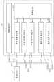
처리 모듈(12)은, 음파 송수신부(121), 프로세서부(122), 데이터 송수신부(123) 및 전력부(124)를 포함할 수 있다.The
음파 송수신부(121)는, 음파 신호를 발생시켜 라이너(L)로 전달하는 음파 신호 송신부(1211) 및 트랜스듀서(11)를 통하여 라이너(L)로부터 반사되는 음파 신호를 수신하는 음파 신호 수신부(1212)를 포함할 수 있다.The sound wave transmitting and receiving
프로세서부(122)는, 음파 신호 수신부(1212)에서 수신된 음파 신호를 분석하여 라이너(L)의 두께에 대한 데이터를 획득할 수 있다. 여기서 음파 신호는 미리 정해질 수 있으며, 정해진 음파 신호의 속도와, 음파 신호 송신부(1211)로부터 발생되고 라이너(L)로 반사되어 음파 신호 수신부(1212)로 수신되기까지 걸리는 시간에 기초하여 라이너(L)의 두께가 측정될 수 있다. 또한, 프로세서부(122)는, 전력을 제어하여 처리 모듈(12)의 동작을 보조할 수 있다.The
데이터 송수신부(123)는, 라이너(L)의 두께에 대한 데이터를 외부로부터 수신하는 무선 데이터 수신부(1231) 및 라이너(L)의 두께에 대한 데이터를 외부로 송신하는 무선 데이터 송신부(1232)를 포함할 수 있다. 무선 데이터 수신부(1231) 및 무선 데이터 송신부(1232)는, 각각 프로세서부(122)에 연결되어 프로세서부(122)로부터 처리된 데이터를 주고받을 수 있으며, 외부와 소통하기 위하여 무선 통신 모듈(wireless communication module)이 내장될 수 있다.The data transmitting and receiving
전력부(124)는, 전력을 수신하는 무선 전력 수신부(1241) 및 프로세서부(122)에 의하여 전력이 제어되는 전력 관리부(1242)를 포함할 수 있다. 이와 같은 구조에 의하면, 스마트 스크류(1)가 대상체의 고관절(O)로 삽입되어 고정되더라도 외부로부터 침습적인 시술을 받지 않고도, 즉 비침습적인 방식으로 전력을 전달받아 인공 관절의 라이너(L)의 두께 데이터를 술자 또는 사용자가 획득할 수 있다.The power unit 124 may include a wireless
코일(13)은, 압전층(112)의 둘레를 감싸도록 스크류 본체의 내부에 배치될 수 있고, 외부로 전자기파(electromagnetic wave)를 송신 또는 외부로부터 전자기파를 수신할 수 있다. 또한, 코일(13)은, 데이터 송수신부(123)에 연결되어 외부로부터 전달되는 데이터 및 전력을 데이터 송수신부(123) 및 전력부(124)로 각각 전달할 수 있다. 예를 들어, 코일(13)은, 전자기파의 형태로서 외부로부터 데이터 및 전력을 수신 또는 외부로 데이터 및 전력을 송신할 수 있다. 이와 같은 구조에 의하면, 코일(13)에 전원이 연결되어 있지 않으므로, 필요할 때마다 전자기파를 발생시켜 스마트 스크류(1)를 동작시킬 수 있다. 또한, 별도의 전원이 필요하지 않으므로, 기존의 스크류의 크기를 유지하며 일반적으로 사용되는 인공 관절을 고정시키는 데 사용될 수 있으며, 별도의 장치나 특유의 구조를 필요로 하지 않는다는 점에서 범용성이 있다.The
투과층(14)은, 코일(13)과 소통할 수 있도록 전자기파가 투과될 수 있다. 이를 위하여, 투과층(14)은, 트랜스듀서(11) 및 처리 모듈(12)을 감싸도록 스크류 본체의 외측에 형성될 수 있다. 이와 같은 구조에 의하면, 투과층(14)이 외부로부터의 충격에 대하여 스크류 본체를 보호하면서도 전자기파를 외부로부터 거의 흡수하여 처리 모듈(12)로 전달할 수 있으므로, 데이터 송수신률이 향상될 수 있다.Electromagnetic waves can be transmitted through the
도 3은 일 실시예에 따른 스마트 스크류를 개략적으로 나타낸 단면도이고, 도 4는 일 실시예에 따른 스마트 스크류를 나타낸 개념도이다.FIG. 3 is a cross-sectional view schematically showing a smart screw according to an embodiment, and FIG. 4 is a conceptual view showing a smart screw according to an embodiment.
도 3 및 도 4를 참조하면, 일 실시예에 따른 스마트 스크류(2)는, 대상체의 고관절(O)에 배치되는 쉘(C)과, 쉘(C)의 내부면에 구비된 라이너(L)를 포함하는 인공 관절을 관통하여 고관절(O)로 삽입되는 스크류 본체, 트랜스듀서(21), 처리 모듈(22)및 투과층(24)을 포함할 수 있다.3 and 4, the
트랜스듀서(21)는, 스크류 본체의 내부에 배치될 수 있다. 트랜스듀서(21)는, 라이너(L)에 인접하게 스크류 본체의 내부에 배치되는 결합층(211), 결합층(211)에 인접하여 배치되는 압전층(212) 및 압전층(212)에 인접하여 배치되는 흡음층(213)을 포함할 수 있다. 트랜스듀서(21)는, 라이너(L)로부터 반사되는 음파 신호를 감지할 수 있을 뿐만 아니라, 전자기파의 형태로 전달되는 전력을 수신할 수 있다.The transducer (21) may be disposed inside the screw body. The
처리 모듈(22)은, 트랜스듀서(21)에 연결되어 음파 신호에 기초하여 라이너(L)의 두께를 측정하고 외부로 라이너(L)의 두께에 대한 데이터를 전달할 수 있다. 처리 모듈(22)은, 음파 송수신부(221), 프로세서부(222), 데이터 송수신부(223) 및 전력부(224)를 포함할 수 있다.The
이와 같은 구조에 의하면, 전력을 전송할 수 있는 코일의 전송 효율이 높지 않은 경우에, 스마트 스크류(2)의 동작 효율이 저하될 수 있으므로, 코일을 사용하지 않고 트랜스듀서(21)가 라이너(L)로부터 반사되는 음파 신호를 감지할 뿐만 아니라 전자기파 형태의 전력도 수신함으로써 스마트 스크류(2)의 공간 효율성을 도모할 수 있다.According to this structure, when the transmission efficiency of the coils capable of transmitting electric power is not high, the operation efficiency of the
도 5는 일 실시예에 따른 스마트 스크류를 개략적으로 나타낸 단면도이고, 도 6은 일 실시예에 따른 스마트 스크류를 나타낸 개념도이다.FIG. 5 is a cross-sectional view schematically showing a smart screw according to an embodiment, and FIG. 6 is a conceptual view showing a smart screw according to an embodiment.
일 실시예에 따른 스마트 스크류(3)는, 대상체의 고관절(O)에 배치되는 쉘(C)과, 쉘(C)의 내부면에 구비된 라이너(L)를 포함하는 인공 관절을 관통하여 고관절(O)로 삽입되는 스크류 본체, 제1트랜스듀서(31), 처리 모듈(32) 및 제2트랜스듀서(33)를 포함할 수 있다. 처리 모듈(32)은, 음파 송수신부(321), 프로세서부(322), 데이터 송수신부(323) 및 전력부(324)를 포함할 수 있다. 구체적으로, 제1트랜스듀서(31)는, 음파 송수신부(321)에 연결될 수 있고, 제2트랜스듀서(33)는, 데이터 송수신부(323) 및 전력부(324)에 각각 연결될 수 있다.The
제1트랜스듀서(31)는, 라이너(L)로부터 반사되는 음파 신호를 감지할 수 있다. 이를 위하여, 제1트랜스듀서(31)는, 라이너(L)에 인접하게 스크류 본체의 근위부에 배치될 수 있다. 제1트랜스듀서(31)는, 제1결합층(311), 제1압전층(312) 및 제1흡음층(313)을 포함할 수 있다. 제2트랜스듀서(33)는, 외부로부터 전력을 수신할 수 있다. 이를 위하여, 제2트랜스듀서(33)는, 제1트랜스듀서(31)와 이격되어 스크류 본체의 말단부에 배치될 수 있다. 제2트랜스듀서(33)는, 제2결합층(331), 제2압전층(332) 및 제2흡음층(333)을 포함할 수 있다.The first transducer (31) can sense a sound wave signal reflected from the liner (L). To this end, the
제1트랜스듀서(31)의 제1압전층(312)은, 음파 신호의 제1주파수대역으로 결정되도록 형성될 수 있다. 예를 들어, 음파 신호의 제1주파수대역(e.g. 고주파용 초음파 대역)으로 결정되도록 제1압전층(312)의 두께가 결정될 수 있다. 제2트랜스듀서(33)의 제2압전층(332)은, 음파 신호의 제2주파수대역으로 결정되도록 형성될 수 있다. 예를 들어, 음파 신호의 제2주파수대역(e.g. 저주파용 초음파 대역)으로 결정되도록 제2압전층(332)의 두께가 결정될 수 있다. 이와 같은 구조에 의하면,The first
이와 같은 구조에 의하면, 하나의 트랜스듀서(31; 33)로 라이너(L)로부터 반사되는 음파 신호를 감지하면서 전력을 수신하는 경우에, 감지를 위한 주파수의 경우 전력을 수신하기 위한 주파수에 비하여 높은 주파수이어야 하므로, 감지와 전력 수신을 동시에 수행할 때 어느 하나의 기능의 효율이 저하될 수 있다. 따라서, 제1트랜스듀서(31)를 라이너(L)에 인접하게 배치되고, 제2트랜스듀서(33)를 제1트랜스듀서(31)와 이격되게 배치함으로써, 서로 다른 주파수 대역에서 서로 다른 기능을 수행할 수 있으며, 제1트랜스듀서(31) 및 제2트랜스듀서(33)의 독립적인 기능 수행으로 인하여 스마트 스크류(3)의 동작 효율이 향상될 수 있다.According to such a structure, when receiving power while sensing a sound wave signal reflected from the liner L by one transducer 31 (33), in the case of a frequency for sensing, a frequency higher than a frequency for receiving power The efficiency of any one of the functions may deteriorate when the detection and the power reception are performed at the same time. Therefore, by disposing the
이상과 같이 실시예들이 비록 한정된 실시예와 도면에 의해 설명되었으나, 해당 기술분야에서 통상의 지식을 가진 자라면 상기의 기재로부터 다양한 수정 및 변형이 가능하다. 예를 들어, 설명된 기술들이 설명된 방법과 다른 순서로 수행되거나, 및/또는 설명된 시스템, 구조, 장치, 회로 등의 구성요소들이 설명된 방법과 다른 형태로 결합 또는 조합되거나, 다른 구성요소 또는 균등물에 의하여 대치되거나 치환되더라도 적절한 결과가 달성될 수 있다.While the present invention has been particularly shown and described with reference to exemplary embodiments thereof, it is to be understood that the invention is not limited to the disclosed exemplary embodiments. For example, it is to be understood that the techniques described may be performed in a different order than the described methods, and / or that components of the described systems, structures, devices, circuits, Lt; / RTI > or equivalents, even if it is replaced or replaced.
1 : 스마트 스크류
11 : 트랜스듀서
12 : 처리 모듈1: Smart screw
11: Transducer
12: Processing module
Claims (10)
Translated fromKorean상기 라이너로부터 반사되는 음파 신호를 감지하는 결합층과, 음파 신호의 주파수가 결정되도록 형성된 압전층과, 음파 신호를 흡수하는 흡음층을 포함하는 트랜스듀서;
상기 라이너를 향하여 음파 신호를 발생시켜 상기 결합층에서 감지된 음파 신호를 수신하고, 수신된 음파 신호에 기초하여 상기 라이너의 두께를 측정하고, 측정된 라이너의 두께에 대한 데이터를 외부로 전달하는 처리 모듈; 및
상기 압전층의 둘레를 감싸도록 배치되고, 외부로 전자기파를 송신 또는 외부로부터 전자기파를 수신하는 코일;
을 포함하는 스마트 스크류.
A screw main body inserted into the hip joint through an artificial joint including a shell disposed at a hip joint of a subject and a liner provided at an inner surface of the shell;
A transducer including a coupling layer for sensing a sound wave signal reflected from the liner, a piezoelectric layer formed to determine the frequency of the sound wave signal, and a sound absorbing layer for absorbing the sound wave signal.
Generating a sound wave signal toward the liner to receive a sound wave signal sensed by the coupling layer, measuring a thickness of the liner based on the received sound wave signal, and transmitting data on the measured thickness of the liner to the outside module; And
A coil arranged to surround the periphery of the piezoelectric layer and transmitting electromagnetic waves to the outside or receiving electromagnetic waves from the outside;
A smart screw containing.
상기 처리 모듈은,
음파 신호를 발생시켜 상기 라이너로 전달하고, 상기 트랜스듀서를 통하여 상기 라이너로부터 반사되는 음파 신호를 수신하는 음파 송수신부;
수신된 음파 신호를 분석하여 상기 라이너의 두께에 대한 데이터를 획득하고, 전력을 제어하는 프로세서부;
상기 코일을 통하여 상기 라이너의 두께에 대한 데이터를 외부와 송수신하는 데이터 송수신부; 및
상기 코일을 통하여 전력을 수신하여 상기 프로세서부에 의하여 전력이 제어되는 전력부;
를 포함하는 스마트 스크류.
The method according to claim 1,
The processing module comprises:
A sound wave transmitting and receiving unit for generating a sound wave signal to transmit the sound wave signal to the liner and receiving a sound wave signal reflected from the liner through the transducer;
A processor for analyzing the received sound wave signal to obtain data on the thickness of the liner and for controlling power;
A data transmitting and receiving unit transmitting and receiving data on the thickness of the liner to the outside through the coil; And
A power unit receiving power through the coil and controlling power by the processor unit;
Smart Screw including.
상기 트랜스듀서 및 상기 처리 모듈의 외측에 형성되고, 상기 코일과 소통되게 전자기파가 투과되는 투과층을 더 포함하는 스마트 스크류.
The method according to claim 1,
And a transmission layer formed on the outside of the transducer and the processing module and through which an electromagnetic wave is transmitted so as to communicate with the coil.
상기 스크류 본체의 내부에 배치되고, 상기 라이너로부터 반사되는 음파 신호를 감지하고 외부로부터 전력을 수신하는 트랜스듀서; 및
상기 트랜스듀서에 연결되어 상기 음파 신호에 기초하여 상기 라이너의 두께를 측정하고 외부로 상기 라이너의 두께에 대한 데이터를 전달하는 처리 모듈;
을 포함하고,
상기 처리 모듈은,
음파 신호를 발생시켜 상기 라이너로 전달하고 상기 트랜스듀서를 통하여 상기 라이너로부터 반사되는 음파 신호를 수신하는 음파 송수신부;
수신된 음파 신호를 분석하여 상기 라이너의 두께에 대한 데이터를 획득하고, 전력을 제어하는 프로세서부;
상기 트랜스듀서를 통하여 상기 라이너의 두께에 대한 데이터를 외부와 송수신하는 데이터 송수신부; 및
상기 트랜스듀서를 통하여 전력을 수신하여 상기 프로세서부에 의하여 전력이 제어되는 전력부;
를 포함하는 스마트 스크류.
A screw main body inserted into the hip joint through an artificial joint including a shell disposed at a hip joint of a subject and a liner provided at an inner surface of the shell;
A transducer disposed within the screw body for sensing an acoustic signal reflected from the liner and receiving power from the exterior; And
A processing module coupled to the transducer for measuring the thickness of the liner based on the sound signal and for communicating data about the thickness of the liner to the exterior;
/ RTI >
The processing module comprises:
A sound wave transmitting / receiving unit for generating a sound wave signal and transmitting the sound wave signal to the liner and receiving a sound wave signal reflected from the liner through the transducer;
A processor for analyzing the received sound wave signal to obtain data on the thickness of the liner and for controlling power;
A data transceiver for transmitting / receiving data on the thickness of the liner to the outside through the transducer; And
A power unit receiving power through the transducer and controlling power by the processor unit;
Smart Screw including.
상기 스크류 본체에 배치되는 제1트랜스듀서와 제2트랜스듀서; 및
상기 제1트랜스듀서와 상기 제2트랜스듀서에 각각 연결되어 상기 라이너의 두께 데이터를 획득하고 외부와 전력을 송수신하는 처리 모듈;
을 포함하고,
상기 제1트랜스듀서는 상기 라이너로부터 반사되는 음파 신호를 감지하고, 상기 제2트랜스듀서는 외부로부터 전력을 수신하는 스마트 스크류.
A screw main body inserted into the hip joint through an artificial joint including a shell disposed at a hip joint of a subject and a liner provided at an inner surface of the shell;
A first transducer and a second transducer disposed in the screw body; And
A processing module connected to the first transducer and the second transducer to acquire thickness data of the liner and transmit / receive electric power to and from the outside;
/ RTI >
Wherein the first transducer senses a sound wave signal reflected from the liner, and the second transducer receives power from the outside.
상기 제1트랜스듀서는, 음파 신호의 제1주파수대역으로 결정되도록 형성된 제1압전층을 포함하고, 상기 제2트랜스듀서는, 음파 신호의 제2주파수대역으로 결정되도록 형성된 제2압전층을 포함하는 스마트 스크류.
8. The method of claim 7,
Wherein the first transducer comprises a first piezoelectric layer formed to be in a first frequency band of an acoustic wave signal and the second transducer comprises a second piezoelectric layer formed to be in a second frequency band of an acoustic wave signal Smart screw.
상기 처리 모듈은,
음파 신호를 발생시켜 상기 라이너로 전달하고 상기 제1트랜스듀서를 통하여 상기 라이너로부터 반사되는 음파 신호를 수신하는 음파 송수신부;
수신된 음파 신호를 분석하여 상기 라이너의 두께에 대한 데이터를 획득하고, 전력을 제어하는 프로세서부;
상기 제2트랜스듀서를 통하여 상기 라이너의 두께에 대한 데이터를 외부와 송수신하는 데이터 송수신부; 및
상기 제2트랜스듀서를 통하여 전력을 수신하여 상기 프로세서부에 의하여 전력이 제어되는 전력부;
를 포함하는 스마트 스크류.8. The method of claim 7,
The processing module comprises:
A sound wave transmitting / receiving unit for generating a sound wave signal and transmitting the sound wave signal to the liner and receiving a sound wave signal reflected from the liner through the first transducer;
A processor for analyzing the received sound wave signal to obtain data on the thickness of the liner and for controlling power;
A data transceiver for transmitting and receiving data on the thickness of the liner to the outside through the second transducer; And
A power unit receiving power through the second transducer and controlling power by the processor unit;
Smart Screw including.
Priority Applications (4)
| Application Number | Priority Date | Filing Date | Title |
|---|---|---|---|
| KR1020160167921AKR101972207B1 (en) | 2016-12-09 | 2016-12-09 | Smart screw |
| US16/467,829US11231395B2 (en) | 2016-12-09 | 2017-12-08 | Smart screw |
| EP17879150.5AEP3552567B1 (en) | 2016-12-09 | 2017-12-08 | Smart screw |
| PCT/KR2017/014383WO2018106057A1 (en) | 2016-12-09 | 2017-12-08 | Smart screw |
Applications Claiming Priority (1)
| Application Number | Priority Date | Filing Date | Title |
|---|---|---|---|
| KR1020160167921AKR101972207B1 (en) | 2016-12-09 | 2016-12-09 | Smart screw |
Publications (2)
| Publication Number | Publication Date |
|---|---|
| KR20180066944A KR20180066944A (en) | 2018-06-20 |
| KR101972207B1true KR101972207B1 (en) | 2019-04-26 |
Family
ID=62491923
Family Applications (1)
| Application Number | Title | Priority Date | Filing Date |
|---|---|---|---|
| KR1020160167921AActiveKR101972207B1 (en) | 2016-12-09 | 2016-12-09 | Smart screw |
Country Status (4)
| Country | Link |
|---|---|
| US (1) | US11231395B2 (en) |
| EP (1) | EP3552567B1 (en) |
| KR (1) | KR101972207B1 (en) |
| WO (1) | WO2018106057A1 (en) |
Families Citing this family (1)
| Publication number | Priority date | Publication date | Assignee | Title |
|---|---|---|---|---|
| US11925475B2 (en)* | 2019-06-28 | 2024-03-12 | Orthosensor Inc. | Orthopedic system for pre-operative, intra-operative, and post-operative assessment |
Citations (2)
| Publication number | Priority date | Publication date | Assignee | Title |
|---|---|---|---|---|
| JP2007530083A (en)* | 2003-07-11 | 2007-11-01 | デピュイ・プロダクツ・インコーポレイテッド | Orthopedic elements with self-contained data storage |
| KR101197923B1 (en)* | 2010-11-23 | 2012-11-05 | 강원대학교산학협력단 | Measuring method and device of cortical bone thickness by using pulse-echo ultrasound |
Family Cites Families (11)
| Publication number | Priority date | Publication date | Assignee | Title |
|---|---|---|---|---|
| US7097662B2 (en) | 2004-08-25 | 2006-08-29 | Ut-Battelle, Llc | In-vivo orthopedic implant diagnostic device for sensing load, wear, and infection |
| US7328131B2 (en)* | 2006-02-01 | 2008-02-05 | Medtronic, Inc. | Implantable pedometer |
| US8029566B2 (en) | 2008-06-02 | 2011-10-04 | Zimmer, Inc. | Implant sensors |
| US8421479B2 (en)* | 2009-06-30 | 2013-04-16 | Navisense | Pulsed echo propagation device and method for measuring a parameter |
| EP2750633A4 (en) | 2011-09-01 | 2014-09-24 | Hip Innovation Technology Llc | Lined femoral cup |
| US8690888B2 (en) | 2011-09-23 | 2014-04-08 | Orthosensor Inc. | Modular active spine tool for measuring vertebral load and position of load |
| WO2014028742A1 (en) | 2012-08-15 | 2014-02-20 | University Of Houston | System and method for monitoring the health of joints |
| JP2016516489A (en) | 2013-03-15 | 2016-06-09 | ウィリアム エル ハンター | Apparatus, system and method for monitoring hip replacements |
| KR101368196B1 (en) | 2013-12-02 | 2014-02-28 | 한국지질자원연구원 | Apparatus for measuring wave transmission velocity and method for measuring wave transmission velocity using thereof |
| KR102243037B1 (en)* | 2014-03-18 | 2021-04-21 | 삼성메디슨 주식회사 | Ultrasonic diagnostic apparatus and operating method for the same |
| KR102209423B1 (en)* | 2014-06-27 | 2021-01-29 | 동우 화인켐 주식회사 | Etching solution composition for metal layer and manufacturing method of an array substrate for liquid crystal display using the same |
- 2016
- 2016-12-09KRKR1020160167921Apatent/KR101972207B1/enactiveActive
- 2017
- 2017-12-08USUS16/467,829patent/US11231395B2/enactiveActive
- 2017-12-08EPEP17879150.5Apatent/EP3552567B1/enactiveActive
- 2017-12-08WOPCT/KR2017/014383patent/WO2018106057A1/ennot_activeCeased
Patent Citations (2)
| Publication number | Priority date | Publication date | Assignee | Title |
|---|---|---|---|---|
| JP2007530083A (en)* | 2003-07-11 | 2007-11-01 | デピュイ・プロダクツ・インコーポレイテッド | Orthopedic elements with self-contained data storage |
| KR101197923B1 (en)* | 2010-11-23 | 2012-11-05 | 강원대학교산학협력단 | Measuring method and device of cortical bone thickness by using pulse-echo ultrasound |
Also Published As
| Publication number | Publication date |
|---|---|
| EP3552567A1 (en) | 2019-10-16 |
| EP3552567A4 (en) | 2020-08-12 |
| US20210190730A1 (en) | 2021-06-24 |
| US11231395B2 (en) | 2022-01-25 |
| KR20180066944A (en) | 2018-06-20 |
| WO2018106057A1 (en) | 2018-06-14 |
| EP3552567B1 (en) | 2022-07-27 |
Similar Documents
| Publication | Publication Date | Title |
|---|---|---|
| JP4904338B2 (en) | Hybrid electromagnetic ultrasonic terminal targeting system | |
| JP7150698B2 (en) | Communication device and method | |
| US9358136B2 (en) | Shielded capacitor sensor system for medical applications and method | |
| EP1674033B1 (en) | Cement restrictor with integrated pressure transducer | |
| US8979758B2 (en) | Sensing module for orthopedic load sensing insert device | |
| US9226694B2 (en) | Small form factor medical sensor structure and method therefor | |
| US8245583B2 (en) | Sensing module having a piezo-resistive sensor for orthopedic load sensing insert device | |
| MX2007005716A (en) | Position tracking of passive resonance-based transponders. | |
| US12274896B2 (en) | Ultrasonic communication in medical devices | |
| KR101972207B1 (en) | Smart screw | |
| Hosur et al. | MagSonic: Hybrid magnetic-ultrasonic wireless interrogation of millimeter-scale biomedical implants with magnetoelectric transducer | |
| US20120157885A1 (en) | Muscular-skeletal force, pressure, and load measurement system and method | |
| WO2001037733A9 (en) | Implant loosening and fracture healing evaluation apparatus and method | |
| WO2008018612A1 (en) | Ultrasound bone fracture healing device, receiver for healing bone fracture, and bone fracture position examining device | |
| JP2017526420A (en) | Orthopedic implant |
Legal Events
| Date | Code | Title | Description |
|---|---|---|---|
| A201 | Request for examination | ||
| PA0109 | Patent application | Patent event code:PA01091R01D Comment text:Patent Application Patent event date:20161209 | |
| PA0201 | Request for examination | ||
| E902 | Notification of reason for refusal | ||
| PE0902 | Notice of grounds for rejection | Comment text:Notification of reason for refusal Patent event date:20180220 Patent event code:PE09021S01D | |
| PG1501 | Laying open of application | ||
| E90F | Notification of reason for final refusal | ||
| PE0902 | Notice of grounds for rejection | Comment text:Final Notice of Reason for Refusal Patent event date:20180817 Patent event code:PE09021S02D | |
| E701 | Decision to grant or registration of patent right | ||
| PE0701 | Decision of registration | Patent event code:PE07011S01D Comment text:Decision to Grant Registration Patent event date:20190118 | |
| PR0701 | Registration of establishment | Comment text:Registration of Establishment Patent event date:20190418 Patent event code:PR07011E01D | |
| PR1002 | Payment of registration fee | Payment date:20190418 End annual number:3 Start annual number:1 | |
| PG1601 | Publication of registration | ||
| PR1001 | Payment of annual fee | Payment date:20220211 Start annual number:4 End annual number:4 | |
| PR1001 | Payment of annual fee | Payment date:20230330 Start annual number:5 End annual number:5 | |
| PR1001 | Payment of annual fee | Payment date:20240306 Start annual number:6 End annual number:6 |