KR101972075B1 - Laser irradiation unit, and laser marking apparatus - Google Patents
Laser irradiation unit, and laser marking apparatusDownload PDFInfo
- Publication number
- KR101972075B1 KR101972075B1KR1020180103036AKR20180103036AKR101972075B1KR 101972075 B1KR101972075 B1KR 101972075B1KR 1020180103036 AKR1020180103036 AKR 1020180103036AKR 20180103036 AKR20180103036 AKR 20180103036AKR 101972075 B1KR101972075 B1KR 101972075B1
- Authority
- KR
- South Korea
- Prior art keywords
- unit
- lens unit
- lens
- laser
- laser irradiation
- Prior art date
- Legal status (The legal status is an assumption and is not a legal conclusion. Google has not performed a legal analysis and makes no representation as to the accuracy of the status listed.)
- Active
Links
Images


Classifications
- B—PERFORMING OPERATIONS; TRANSPORTING
- B23—MACHINE TOOLS; METAL-WORKING NOT OTHERWISE PROVIDED FOR
- B23K—SOLDERING OR UNSOLDERING; WELDING; CLADDING OR PLATING BY SOLDERING OR WELDING; CUTTING BY APPLYING HEAT LOCALLY, e.g. FLAME CUTTING; WORKING BY LASER BEAM
- B23K26/00—Working by laser beam, e.g. welding, cutting or boring
- B23K26/352—Working by laser beam, e.g. welding, cutting or boring for surface treatment
- B—PERFORMING OPERATIONS; TRANSPORTING
- B23—MACHINE TOOLS; METAL-WORKING NOT OTHERWISE PROVIDED FOR
- B23K—SOLDERING OR UNSOLDERING; WELDING; CLADDING OR PLATING BY SOLDERING OR WELDING; CUTTING BY APPLYING HEAT LOCALLY, e.g. FLAME CUTTING; WORKING BY LASER BEAM
- B23K26/00—Working by laser beam, e.g. welding, cutting or boring
- B23K26/02—Positioning or observing the workpiece, e.g. with respect to the point of impact; Aligning, aiming or focusing the laser beam
- B23K26/06—Shaping the laser beam, e.g. by masks or multi-focusing
- B23K26/064—Shaping the laser beam, e.g. by masks or multi-focusing by means of optical elements, e.g. lenses, mirrors or prisms
- B23K26/0648—Shaping the laser beam, e.g. by masks or multi-focusing by means of optical elements, e.g. lenses, mirrors or prisms comprising lenses
- B—PERFORMING OPERATIONS; TRANSPORTING
- B23—MACHINE TOOLS; METAL-WORKING NOT OTHERWISE PROVIDED FOR
- B23K—SOLDERING OR UNSOLDERING; WELDING; CLADDING OR PLATING BY SOLDERING OR WELDING; CUTTING BY APPLYING HEAT LOCALLY, e.g. FLAME CUTTING; WORKING BY LASER BEAM
- B23K26/00—Working by laser beam, e.g. welding, cutting or boring
- B23K26/14—Working by laser beam, e.g. welding, cutting or boring using a fluid stream, e.g. a jet of gas, in conjunction with the laser beam; Nozzles therefor
- B23K26/1462—Nozzles; Features related to nozzles
- B—PERFORMING OPERATIONS; TRANSPORTING
- B23—MACHINE TOOLS; METAL-WORKING NOT OTHERWISE PROVIDED FOR
- B23K—SOLDERING OR UNSOLDERING; WELDING; CLADDING OR PLATING BY SOLDERING OR WELDING; CUTTING BY APPLYING HEAT LOCALLY, e.g. FLAME CUTTING; WORKING BY LASER BEAM
- B23K26/00—Working by laser beam, e.g. welding, cutting or boring
- B23K26/70—Auxiliary operations or equipment
- B23K26/702—Auxiliary equipment
- B23K26/705—Beam measuring device
- B—PERFORMING OPERATIONS; TRANSPORTING
- B23—MACHINE TOOLS; METAL-WORKING NOT OTHERWISE PROVIDED FOR
- B23K—SOLDERING OR UNSOLDERING; WELDING; CLADDING OR PLATING BY SOLDERING OR WELDING; CUTTING BY APPLYING HEAT LOCALLY, e.g. FLAME CUTTING; WORKING BY LASER BEAM
- B23K26/00—Working by laser beam, e.g. welding, cutting or boring
- B23K26/70—Auxiliary operations or equipment
- B23K26/702—Auxiliary equipment
- B23K26/706—Protective screens
- B—PERFORMING OPERATIONS; TRANSPORTING
- B23—MACHINE TOOLS; METAL-WORKING NOT OTHERWISE PROVIDED FOR
- B23K—SOLDERING OR UNSOLDERING; WELDING; CLADDING OR PLATING BY SOLDERING OR WELDING; CUTTING BY APPLYING HEAT LOCALLY, e.g. FLAME CUTTING; WORKING BY LASER BEAM
- B23K2101/00—Articles made by soldering, welding or cutting
- B23K2101/006—Vehicles
Landscapes
- Engineering & Computer Science (AREA)
- Physics & Mathematics (AREA)
- Optics & Photonics (AREA)
- Plasma & Fusion (AREA)
- Mechanical Engineering (AREA)
- Laser Beam Processing (AREA)
Abstract
Description
Translated fromKorean본 발명은 레이저 조사 유닛 및 레이저 각인 장치에 관한 것으로서, 보다 상세하게는, 전단에 배치되며 소정의 케이블과 연결되어 외부 광원에서 공급되는 빔이 수광되는 수광부, 후단에 배치되며 외부로 빔을 조사하는 노즐부, 상기 수광부와 상기 레이저 노즐 사이에 구비되며 복수 개의 렌즈를 포함하는 광학 모듈, 및 상기 광학 모듈이 내장되는 유닛 하우징을 포함하며, 초점거리를 동일하게 유지하면서 빔의 면적을 가변시킬 수 있는 레이저 조사 유닛 및 레이저 조사 유닛을 포함한 레이저 각인 장치를 제공하는 데 있다.The present invention relates to a laser irradiation unit and a laser engraving device, and more particularly, is disposed at the front end and connected to a predetermined cable, the light receiving unit receiving the beam supplied from an external light source, the rear end is arranged to irradiate the beam to the outside An optical module is provided between the nozzle unit, the light receiving unit, and the laser nozzle, and includes a plurality of lenses, and a unit housing in which the optical module is built, and can change the area of the beam while maintaining the same focal length. The present invention provides a laser engraving device including a laser irradiation unit and a laser irradiation unit.
차량의 차체에는 소정의 차대번호(VIN : Vehicle Identification Number)가 각인된다. 차대번호는 제품의 생산관리 및 이력관리를 위하여 각인되는 것으로서, 생산국가, 제작사, 차종 등을 나타내는 알파벳 및 숫자로 구성된다.A predetermined vehicle identification number (VIN) is imprinted on the vehicle body. The chassis number is imprinted for the production management and the history management of the product, and is composed of alphabets and numbers representing the country of origin, the manufacturer, and the vehicle model.
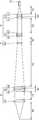
이러한 차대번호의 각인을 위해, 펄스 레이저를 이용한 레이저 각인 장치가 사용되고 있다. 도 1 과 같이, 종래의 레이저 각인 장치는 소정의 펄스 레이저 발생부(P)에서 생성된 레이저 빔을 전달받아서 소정의 노즐을 통해 타겟(T)에 대해 각인 공정을 수행하는 레이저 조사 유닛(Q)과, 상기 레이저 조사 유닛(Q)을 이동시켜서 문자가 각인되도록 하는 다관절 매니퓰레이터(R) 장치를 포함한다.For the marking of such a chassis number, a laser engraving device using a pulse laser is used. As shown in FIG. 1, the conventional laser marking device receives a laser beam generated by a predetermined pulse laser generator P and performs a marking process on a target T through a predetermined nozzle. And a multi-joint manipulator (R) device for moving the laser irradiation unit Q to cause a character to be engraved.
종래 기술에 따르면, 레이저 각인 장치를 이용하여 각인을 수행할 때, 레이저 빔의 크기를 가변시키고자 할 때, 레이저 빔의 초점거리가 일정하게 유지되지 않음으로써, 작동 제어가 어려운 문제가 있었다. 이는 광학적으로, 빔의 초점거리와 빔의 크기는 서로 영향을 받기 때문이다.According to the prior art, when performing the stamping using the laser engraving device, when the size of the laser beam is to be changed, the focal length of the laser beam is not kept constant, there is a problem that operation control is difficult. This is because optically, the focal length of the beam and the size of the beam are influenced by each other.
또한, 각인 과정에서 발생하는 각종 미세한 입자로 이루어지는 스패터(spatter)에 의해서, 레이저 각인 장치 내의 각종 장치가 오염되거나 손상되는 문제도 발생하였다. 특히, 각인 대상물에 대해서 레이저 빔을 조사하는 노즐, 또는 각인 대상물과 노즐 사이의 거리를 측정하는 거리 센서 등이 쉽게 오염되어, 각인이 비정상적으로 이루어지거나, 또는 운영 비용이 증가하는 문제가 발생하였다.In addition, a problem is caused that various devices in the laser engraving device are contaminated or damaged by a spatter made of various fine particles generated during the marking process. In particular, a nozzle for irradiating a laser beam to a marking object or a distance sensor for measuring the distance between the marking object and the nozzle is easily contaminated, resulting in abnormal marking or an increase in operating costs.
또한, 레이저 빔이 정상적인 출력을 갖는지 확인하기 어려워서, 각인이 비정상적으로 이루어지는 문제도 발생하였다.In addition, it is difficult to confirm whether or not the laser beam has a normal output, causing a problem that the stamping is abnormal.
본 발명의 기술적 과제는, 초점거리를 동일하게 유지하면서 빔의 면적을 가변시킬 수 있는 레이저 조사 유닛 및 레이저 조사 유닛을 포함한 레이저 각인 장치를 제공하는 데 있다.SUMMARY OF THE INVENTION The present invention has been made in an effort to provide a laser engraving apparatus including a laser irradiation unit and a laser irradiation unit capable of varying an area of a beam while maintaining the same focal length.
본 발명의 또 다른 과제는, 각인 과정에서 발생하는 스패터(spatter)에 의해서, 레이저 각인 장치 내의 각종 장치가 오염되거나 손상되는 것이 방지되는 레이저 조사 유닛 및 레이저 조사 유닛을 포함한 레이저 각인 장치를 제공하는 데 있다.It is still another object of the present invention to provide a laser engraving apparatus including a laser irradiation unit and a laser irradiation unit in which various devices in the laser marking apparatus are prevented from being contaminated or damaged by a spatter generated during the marking process. There is.
본 발명의 또 다른 과제는, 레이저 빔의 출력을 편리하게 확인할 수 있는 레이저 조사 유닛 및 레이저 조사 유닛을 포함한 레이저 각인 장치를 제공하는 데 있다.Another object of the present invention is to provide a laser engraving device including a laser irradiation unit and a laser irradiation unit which can conveniently check the output of the laser beam.
상기 목적을 달성하기 위하여, 본 발명에 따른 레이저 조사 유닛은, 레이저 각인 장치에 사용되는 레이저 조사 유닛으로서, 전단에 배치되며 소정의 케이블과 연결되어 외부 광원에서 공급되는 빔이 수광되는 수광부, 후단에 배치되며 외부로 빔을 조사하는 노즐부, 상기 수광부와 상기 레이저 노즐 사이에 구비되며 복수 개의 렌즈를 포함하는 광학 모듈, 및 상기 광학 모듈이 내장되는 유닛 하우징을 포함하며,In order to achieve the above object, the laser irradiation unit according to the present invention is a laser irradiation unit used in the laser engraving device, disposed in the front end and connected to a predetermined cable, the light receiving portion, the rear end is received by the beam supplied from an external light source A nozzle unit disposed to be disposed to irradiate a beam to the outside, an optical module provided between the light receiving unit and the laser nozzle and including a plurality of lenses, and a unit housing in which the optical module is embedded,
상기 광학 모듈은, 상기 노즐부를 통과하여 조사되는 레이저 빔의 초점 거리를 일정하게 유지한 상태에서 상기 초점 거리 위치에서의 빔 사이즈를 가변할 수 있게 구성된다.The optical module is configured to be able to vary the beam size at the focal length position while keeping the focal length of the laser beam irradiated through the nozzle portion constant.
바람직하게는, 상기 광학 모듈은, 상기 수광부와 인접하게 배치된 전방 렌즈 유닛, 상기 전방 렌즈 유닛의 후방에 배치되는 후방 렌즈 유닛, 및 상기 전방 렌즈 유닛과 후방 렌즈 유닛 사이에 배치되는 가변 렌즈 유닛을 포함하며, 상기 가변 렌즈 유닛은 상기 후방 렌즈 유닛으로 입사하는 빔의 면적을 가변시키게 구성된다.Preferably, the optical module includes a front lens unit disposed adjacent to the light receiving unit, a rear lens unit disposed behind the front lens unit, and a variable lens unit disposed between the front lens unit and the rear lens unit. And the variable lens unit is configured to vary an area of a beam incident to the rear lens unit.
바람직하게는, 상기 광학 모듈은, 평행광을 생성하는 제1 렌즈 유닛, 상기 제1 렌즈의 후방에 배치되며 소정의 초점 거리를 갖고 빔을 집광하는 제2 렌즈 유닛, 상기 제2 렌즈 유닛 후방에 배치되는 가변 렌즈 유닛, 상기 가변 렌즈 유닛의 후방에 배치되며 평행광을 생성하는 제3 렌즈 유닛, 및 상기 제3 렌즈 유닛의 후방에 배치되며 소정의 초점 거리를 갖고 빔을 집광하는 제4 렌즈 유닛을 포함하며, 상기 가변 렌즈 유닛은 상기 제3 렌즈 유닛으로 입사하는 빔의 면적을 가변시킨다.Preferably, the optical module includes a first lens unit for generating parallel light, a second lens unit arranged behind the first lens and having a predetermined focal length, and collecting a beam, behind the second lens unit. A variable lens unit arranged behind, a third lens unit arranged behind the variable lens unit to generate parallel light, and a fourth lens unit arranged behind the third lens unit and condensing the beam with a predetermined focal length The variable lens unit may vary an area of a beam incident to the third lens unit.
바람직하게는, 상기 가변 렌즈 유닛은, 상기 제2 렌즈 유닛과 상기 제3 렌즈 유닛 사이에서 위치 이동 가능한 렌즈를 포함하여, 상기 제2 렌즈 유닛과 상기 가변 렌즈 유닛 사이의 거리 및 상기 가변 렌즈 유닛과 상기 제3 렌즈 유닛 사이의 거리가 가변한다.Preferably, the variable lens unit includes a lens that is positionally movable between the second lens unit and the third lens unit, and the distance between the second lens unit and the variable lens unit and the variable lens unit; The distance between the third lens units is variable.
바람직하게는, 상기 노즐부는 테프론 재질로 구성되며, 탈착 가능하게 구성된다.Preferably, the nozzle portion is made of Teflon material, is configured to be removable.
바람직하게는, 검사부를 더 포함하되, 상기 검사부는, 상기 유닛 하우징 내에 배치되되 상기 광학 모듈을 통과하는 빔 경로 상에 배치되며, 소정의 투과율 및 반사율을 갖는 미러, 및 상기 미러에서 반사되는 빔을 포착하여 빔의 세기를 판독하는 파워 센서를 포함한다.Preferably, the inspection unit further comprises an inspection unit, the inspection unit is disposed on the beam path passing through the optical module disposed in the unit housing, the mirror having a predetermined transmittance and reflectance, and the beam reflected from the mirror And a power sensor that captures and reads the intensity of the beam.
바람직하게는, 상기 검사부는, 상기 유닛 하우징에 구비되며 상기 미러가 탑재되는 탑재부를 포함한다.Preferably, the inspection unit includes a mounting portion provided in the unit housing and on which the mirror is mounted.
본 발명의 일 실시예에 의한 레이저 각인 장치는, 레이저 조사 유닛; 상기 레이저 조사 유닛이 내부에 탑재되는 아우터 커버; 및 거리 측정 장치;를 포함하며, 상기 거리 측정 장치는, 상기 아우터 커버의 하부에 배치되어 각인 대상물과 레이저 조사 유닛 사이의 거리를 측정하는 거리 측정 센서, 상기 거리 측정 센서를 보호하며 광 투과성 재질로 구성되는 보호 윈도우, 및 상기 보호 윈도우의 하부를 선택적으로 커버하도록 개폐가능한 보호 커버를 포함한다.Laser engraving device according to an embodiment of the present invention, the laser irradiation unit; An outer cover on which the laser irradiation unit is mounted; And a distance measuring device, wherein the distance measuring device includes a distance measuring sensor disposed under the outer cover to measure a distance between an imprinted object and a laser irradiation unit, and protecting the distance measuring sensor with a light transmissive material. A protective window configured, and a protective cover openable to selectively cover a lower portion of the protective window.
바람직하게는, 에어 커튼 장치;를 더 포함하며, 상기 에어 커튼 장치는 노즐부가 위치하는 방향으로 에어를 분사하는 노즐 바디, 및 상기 노즐 바디의 위치가 가변하도록 하는 연결부를 포함한다.Preferably, the apparatus further comprises an air curtain device, wherein the air curtain device includes a nozzle body for injecting air in a direction in which the nozzle part is located, and a connection part for changing the position of the nozzle body.
본 발명에 따라서, 초점거리를 동일하게 유지하면서 빔의 면적을 가변시킬 수 있는 레이저 조사 유닛 및 레이저 조사 유닛을 포함한 레이저 각인 장치가 제공될 수 있다. 특히, 레이저 조사 유닛 내의 렌즈 유닛을 최적으로 구성함으로써, 초점에서의 빔의 균일도를 일정하게 유지하는 상태로, 초점거리를 동일하게 유지함과 동시에 빔의 면적을 가변시킬 수 있다.According to the present invention, a laser engraving device including a laser irradiation unit and a laser irradiation unit capable of varying the area of the beam while keeping the focal length the same can be provided. In particular, by optimally configuring the lens unit in the laser irradiation unit, it is possible to change the area of the beam while maintaining the same focal length while maintaining uniformity of the beam at the focus.
또한, 본 발명에 의해서, 각인 과정에서 발생하는 스패터(spatter)에 의해서, 레이저 각인 장치 내의 각종 장치가 오염되거나 손상되는 것이 방지되는 레이저 조사 유닛 및 레이저 조사 유닛을 포함한 레이저 각인 장치가 제공될 수 있다.In addition, according to the present invention, a laser engraving apparatus including a laser irradiation unit and a laser irradiation unit in which various devices in the laser marking apparatus are prevented from being contaminated or damaged by a spatter generated during the marking process can be provided. have.
아울러, 본 발명에 의해서, 레이저 빔의 출력을 편리하게 확인할 수 있는 레이저 조사 유닛 및 레이저 조사 유닛을 포함한 레이저 각인 장치가 제공될 수 있다.In addition, according to the present invention, a laser engraving apparatus including a laser irradiation unit and a laser irradiation unit capable of conveniently checking the output of a laser beam may be provided.
도 1은 종래 기술에 의한 레이저 각인 장치의 일 예를 나타낸 도면이다.
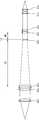
도 2 는 본 발명에 의한 레이저 각인 장치의 전체 형상을 나타낸 도면이다.
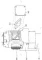
도 3 은 본 발명에 의한 레이저 각인 장치의 내부 구조를 나타낸 도면이다.
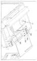
도 4 는 본 발명에 의한 레이저 조사 유닛을 나타낸 도면이다.
도 5 는 본 발명의 일 실시예에 의한 레이저 조사 유닛의 광학 모듈의 구조를 나타낸 도면이다.
도 6 및 7 은 본 발명의 일 실시예에 의한 광학 모듈의 작동을 나타낸 도면이다.
도 8 은 렌즈에 입사하는 빔과, 렌즈를 통과한 빔의 초점 거리에서의 면적 간의 관계를 나타낸 것이다.
도 9 내지 12 도는 동일한 초점 거리에서, 빔의 면적, 및 빔의 세기 분포를 나타낸 도면이다.
도 13 및 14 는 본 발명의 일 실시예에 의한 레이저 조사 유닛의 검사부의 구조를 나타낸 도면이다.
도 15 및 16 은 본 발명의 일 실시예에 의한 레이저 각인 장치의 거리 측정 장치의 구조를 나타낸 도면이다.
도 17 은 에어 커튼 장치의 구조를 나타낸 도면이다.1 is a view showing an example of a laser engraving device according to the prior art.
2 is a view showing the overall shape of the laser engraving device according to the present invention.
3 is a view showing the internal structure of the laser engraving device according to the present invention.
4 is a view showing a laser irradiation unit according to the present invention.
5 is a view showing the structure of an optical module of a laser irradiation unit according to an embodiment of the present invention.
6 and 7 are views showing the operation of the optical module according to an embodiment of the present invention.
8 shows the relationship between the area of the beam incident on the lens and the focal length of the beam passing through the lens.
9 to 12 are diagrams showing the area of the beam and the intensity distribution of the beam at the same focal length.
13 and 14 are views showing the structure of the inspection unit of the laser irradiation unit according to an embodiment of the present invention.
15 and 16 are views showing the structure of the distance measuring device of the laser engraving device according to an embodiment of the present invention.
17 is a view showing the structure of an air curtain device.
이하, 첨부된 도면을 참조하여, 본 발명에 따른 바람직한 실시예에 대하여 설명한다. 본 실시예는 예시적인 것으로 어떤 식으로든 본 발명을 제한하는 것은 아니다.Hereinafter, exemplary embodiments of the present invention will be described with reference to the accompanying drawings. This example is illustrative and does not limit the invention in any way.
도 2 는 본 발명에 의한 레이저 각인 장치(20)의 전체 형상을 나타낸 도면이고, 도 3 은 본 발명에 의한 레이저 각인 장치(20)의 내부 구조를 나타낸 도면이며, 도 4 는 본 발명에 의한 레이저 조사 유닛(10)을 나타낸 도면이다.2 is a view showing the overall shape of the
먼저, 본 발명에 따른 레이저 조사 유닛(10)을 포함한 레이저 각인 장치(20)에 대해서 설명한다.First, the
본 발명에 따른 레이저 각인 장치(20)는, 레이저 조사 유닛(10); 레이저 조사 유닛(10)이 내부에 탑재되는 아우터 커버(22)를 포함한다. 아울러, 거리 측정 장치(300), 및 에어 커튼 장치(400)를 포함할 수 있다. 이때, 상기 거리 측정 장치(300)는, 아우터 커버의 하부에 배치되어 각인 대상물과 레이저 조사 유닛(10) 사이의 거리를 측정하는 거리 측정 센서(310)와, 상기 거리 측정 센서(310)를 보호하는 보호 윈도우(320); 및 보호 윈도우(320)의 하부를 선택적으로 커버하도록 개폐가능한 보호 커버(330);를 포함할 수 있다.The
레이저 조사 유닛(10)은 아우터 커버(22) 내에 탑재된다. 아우터 커버(22)는 레이저 각인 장치(20)의 외관을 구성한다. 아우터 커버(22) 내부에는 상기 레이저 조사 유닛(10)이 탑재될 수 있다. 아우터 커버(22) 내에는 레이저 조사 유닛(10)을 위치 이동시킬 수 있는 소정의 액츄에이터가 구비될 수 있다. 아울러, 아우터 커버(22)는 소정의 다관절 매니퓰레이터(30)와 연결되어 변위될 수 있다. 아우터 커버(22)는 내스패터 성질을 갖도록 SUS 재질로 구성되며, 테프론 코팅을 가질 수 있다.The
거리 측정 장치(300) 및 에어 커튼 장치(400)에 대해서는 아래에서 상세히 설명한다.The distance measuring
이하에서는, 본 발명에 따른 레이저 조사 유닛(10)에 대해서 설명한다.Hereinafter, the
본 발명에 따른 레이저 조사 유닛(10)은, 레이저 각인 장치(20)에 사용되는 레이저 조사 유닛(10)으로서, 수광부(12), 노즐부(14), 광학 모듈(100), 및 유닛 하우징(16)을 포함하여 구성될 수 있다. 아울러, 바람직하게는, 검사부(200)를 더 포함할 수 있다.The
수광부(12)는 레이저 조사 유닛(10)의 전단에 배치된다. 수광부(12)는 외부의 광원과 연결됨으로써, 외부에서 발생하는 빔을 후술하는 광학 모듈(100)로 제공할 수 있는 부재이다. 예컨대, 수광부(12)는 소정의 광 케이블(L)이 연결될 수 있는 케이블 연결 부재일 수 있다.The
노즐부(14)는 레이저 조사 유닛(10)의 후단에 배치되어, 광학 모듈(100)을 통과한 빔을 각인 대상물에 조사시킬 수 있는 부재이다. 노즐부(14)는 반드시 광학 모듈(100)과 별개로 구성되지 않으며, 광학 모듈(100)의 일 부분과 결합된 구성을 가질 수도 있다.The
바람직하게는, 노즐부(14)는 내열성과 내부식성 및 내마찰성이 있는 테프론 재질로 구성되며, 탈착 가능한 구성을 가질 수 있다. 따라서, 내스패터(spatter)성을 가질 수 있다.Preferably, the
광학 모듈(100)은 수광부(12)와 노즐부(14) 사이에 배치되며, 복수 개의 렌즈를 포함하는 장치이다. 광학 모듈(100)은 레이저 조사 유닛(10)의 외관을 구성하는 유닛 하우징(16) 내에 내장된다.The
광학 모듈(100)은 상기 수광부(12)와 상기 레이저 노즐 사이에 구비되며 복수 개의 렌즈를 포함한다. 광학 모듈(100)은, 상기 노즐부(14)를 통과하여 조사되는 레이저 빔의 초점 거리가 일정하게 유지되며 상기 초점 거리 위치에서 빔 사이즈를 가변할 수 있게 구성된다.The
유닛 하우징(16)은 레이저 조사 유닛(10)의 외관을 구성하며, 내부에 상기 광학 모듈(100)이 내장될 수 있게 구성된다. 유닛 하우징(16)의 전단에는 상기 수광부(12)가 구비되며, 후단에는 상기 노즐부(14)가 구비된다. 앞서 설명한 바와 같이, 상기 수광부(12)에는 소정의 광 케이블이 연결될 수 있으며, 상기 노즐부(14)는 유닛 하우징(16)으로부터 탈착 가능하여 교체 가능한 구성을 가질 수 있다.The
이하에서는 광학 모듈(100)에 대해서 보다 상세하게 설명한다.Hereinafter, the
도 5 는 본 발명의 일 실시예에 의한 레이저 조사 유닛(10)의 광학 모듈(100)의 구조를 나타낸 도면이며, 도 6 및 7 은 본 발명의 일 실시예에 의한 광학 모듈(100)의 작동을 나타낸 도면이다. 아울러, 도 8 은 렌즈에 입사하는 빔과, 렌즈를 통과한 빔의 초점 거리에서의 면적 간의 관계를 나타낸 것이다.5 is a view showing the structure of the
도면에 도시된 바와 같이, 광학 모듈(100)은 복수 개의 렌즈를 포함하여 구성되며, 상기 렌즈가 상기 설명한 유닛 하우징(16) 내에 배치될 수 있다.As shown in the figure, the
예컨대, 크게 분류하여, 광학 모듈(100)은 전방 렌즈 유닛(A)과, 후방 렌즈 유닛(B), 및 상기 전방 렌즈 유닛(A)과 후방 렌즈 유닛(B) 사이에 배치되는 가변 렌즈 유닛(C)을 포함하여 구성될 수 있다.For example, largely classified, the
수광부(12)를 통해서 전달된 빔은, 상기 전방 렌즈 유닛(A)과 가변 렌즈 유닛(C), 및 후방 렌즈 유닛(B)을 통과하여 노즐부(14)를 통해서 각인 대상물로 조사된다.The beam transmitted through the
전방 렌즈 유닛(A)은 빔을 소정의 초점 거리를 가지며 집광되도록 한다.The front lens unit A causes the beam to be focused with a predetermined focal length.
가변 렌즈 유닛(C)은 전방 렌즈 유닛(A)을 통과한 빔의 면적을 확대하여 후방 렌즈 유닛(B)으로 전달한다. 이때, 가변 렌즈 유닛(C)의 작동에 따라서 후방 렌즈 유닛(B)으로 전달되는 빔의 면적이 가변될 수 있다.The variable lens unit C enlarges the area of the beam passing through the front lens unit A and transmits it to the rear lens unit B. In this case, the area of the beam transmitted to the rear lens unit B may vary according to the operation of the variable lens unit C. FIG.
후방 렌즈 유닛(B)은 가변 렌즈 유닛(C)을 통해 전달된 빔이 소정의 초점거리를 갖고 각인 대상물에 조사되도록 한다. 이때, 가변 렌즈 유닛(C)에 의해서 후방 렌즈 유닛(B)으로 전달되는 빔의 면적이 가변됨에 따라서 후방 렌즈 유닛(B)을 통과하여 각인 대상물로 조사되는 빔은 초점거리를 동일하게 유지하면서 조사 면적이 가변될 수 있다.The rear lens unit B causes the beam transmitted through the variable lens unit C to be irradiated to the imprinted object with a predetermined focal length. At this time, as the area of the beam transmitted to the rear lens unit B by the variable lens unit C is variable, the beam irradiated to the imprinted object through the rear lens unit B is irradiated while maintaining the focal length at the same time. The area can vary.
광학 모듈(100)의 구체적인 일 실시 형태를 설명하면 이하와 같다.A specific embodiment of the
광학 모듈(100)은 제1 렌즈 유닛(110), 제2 렌즈 유닛(120), 제3 렌즈 유닛(140), 제4 렌즈 유닛(150), 및 가변 렌즈 유닛(C)을 포함하여 구성될 수 있다. 이때, 제1 렌즈 유닛(110)과 제2 렌즈 유닛(120)은 상기 전방 렌즈 유닛(A)을 구성하며, 제3 렌즈 유닛(140)과 제4 렌즈 유닛(150)은 상기 후방 렌즈 유닛(B)을 구성할 수 있다.The
제1 렌즈 유닛(110)은 광학 모듈(100)의 전단에 배치되며, 수광부(12)를 통해 제공된 레이저를 변조하여 평행광이 되도록 할 수 있다. 예컨대, 제1 렌즈 유닛(110)은 빔 경로 방향으로 겹쳐진 2 개의 렌즈로 구성되며, 제1 렌즈(112)와 제2 렌즈(114)를 포함할 수 있다.The
제2 렌즈 유닛(120)은 제1 렌즈 유닛(110)의 후방에 배치되며, 상기 제1 렌즈 유닛(110)에 의해서 변조된 평행광을 다시 변조하여 소정의 초점 거리를 갖고 집광되도록 한다. 예컨대, 제2 렌즈 유닛(120)은 빔 경로 방향으로 겹쳐진 2 개의 렌즈로 구성되며, 제3 렌즈(122)와 제4 렌즈(124)를 포함할 수 있다.The
가변 렌즈 유닛(C)은 상기 제2 렌즈 유닛(120) 후방에 배치되며, 상기 제2 렌즈 유닛(120)을 통과한 빔을 확대하여 상기 빔이 소정의 면적을 갖고 제3 렌즈 유닛(140)으로 전달되도록 한다. 예컨대, 가변 렌즈 유닛은 제5 렌즈(130)와 소정의 액츄에이터(미도시)를 포함할 수 있다.The variable lens unit C is disposed behind the
제3 렌즈 유닛(140)은 상기 가변 렌즈 유닛(C) 후방에 배치되며, 상기 가변 렌즈를 통과한 빔을 변조하여 다시 평행광이 되도록 할 수 있다. 예컨대, 제3 렌즈 유닛(140)은 빔 경로 방향으로 겹쳐진 2 개의 렌즈로 구성되며, 제6 렌즈(142)와 제7 렌즈(144)를 포함할 수 있다.The
제4 렌즈 유닛(150)은 상기 제3 렌즈 유닛(140)을 통과하여 평행광으로 변조된 빔을 소정의 초점 거리를 갖고 집광되도록 한다. 제4 렌즈 유닛(150)은 제8 렌즈(150)를 포함할 수 있다. 제4 렌즈 유닛(150)을 구성하는 렌즈는 하나일 수 있으며, 따라서 본 명세서에서는 제4 렌즈 유닛(150)과, 제8 렌즈(150)를 동일 도면 부호로 표기하였다. 단, 이에 반드시 한정하지는 않는다.The
이하에서는 가변 렌즈 유닛(C)의 구체적인 실시 형태 및 작동에 대해서 설명한다.Hereinafter, specific embodiments and operations of the variable lens unit C will be described.
가변 렌즈 유닛(C)은 상기 제2 렌즈 유닛(120)과 제3 렌즈 유닛(140) 사이에 배치되어, 제3 렌즈 유닛(140)으로 전달되는 빔의 면적을 가변시키는 장치이다. 제3 렌즈 유닛(140)으로 전달되는 빔의 면적이 확대되면 노즐부(14)를 통해서 각인 대상물로 조사되는 빔의 면적이 축소된다. 반대로, 제3 렌즈 유닛(140)으로 전달되는 빔의 면적이 축소되면 노즐부(14)를 통해서 각인 대상물로 조사되는 빔의 면적이 확대된다. 단, 이와 같이 각인 대상물로 조사되는 빔의 면적이 가변함에도 불구하고, 노즐부(14)를 통해 각인 대상물로 조사되는 빔의 초점 거리는 동일하게 유지된다.The variable lens unit C is disposed between the
이러한 원리를 수식과 예를 통해 설명하면 아래와 같다. 도 8 은 렌즈에 입사하는 빔과, 렌즈를 통과한 빔의 초점 거리에서의 면적 간의 관계를 나타낸 것이며, 아래 식 1 은 도 8 에 도시된 관계식을 정리한 것이다.This principle is explained through the formulas and examples. FIG. 8 illustrates the relationship between the beam incident on the lens and the area at the focal length of the beam passing through the lens, and

<식 1><
위 식 1 에서 W 는 렌즈에 입력되는 빔의 크기(면적, 직경 등)이며, W0 는 초점 거리에서의 빔의 크기이다. 즉, 초점에서 빔의 크기(Focal Spot Size)는 렌즈에 입력되는 빔의 크기에 반비례한다. 따라서, 본 발명은 가변 렌즈 유닛(C)을 가져서, 후방 렌즈 유닛(B)에 입력되는 빔의 크기를 가변시킴으로써, 결과적으로 노즐부(14)를 통해 각인 대상물에 조사되는 빔의 크기를 가변시키는 것이다.In
일 실시예에 의하면, 상기 가변 렌즈 유닛(C)을 구성하는 제5 렌즈(130)는, 상기 제2 렌즈 유닛(120)과 상기 제3 렌즈 유닛(140) 사이에서 위치 이동할 수 있다. 이때, 상기 가변 렌즈 유닛(C)에 구비된 액츄에이터는 상기 제5 렌즈(130)를 위치 이동시킬 수 있다. 따라서, 상기 제2 렌즈 유닛(120)과 상기 제5 렌즈(130) 사이의 거리 및 상기 제5 렌즈(130)와 상기 제3 렌즈 유닛(140) 사이의 거리가 가변하는 구성을 가질 수 있다.In example embodiments, the
예컨대, 도 6에 도시된 바와 같이, 제5 렌즈(130)가 제2 렌즈 유닛(120)에 근접한 제1 위치 P1 에 위치하면, 제2 렌즈 유닛(120)과 상기 제5 렌즈(130) 사이의 거리는 작아져서 M1 이 되고, 상기 제5 렌즈(130)와 상기 제3 렌즈 유닛(140) 사이의 거리는 커져서 N1 이 된다. 이 경우에는, 노즐부(14)를 통해 각인 대상물로 조사되는 빔의 면적이 확대되어 소정의 제1 면적을 갖는다.For example, as shown in FIG. 6, when the
반대로, 도 7 에 도시된 바와 같이, 제5 렌즈(130)가 제3 렌즈 유닛(140)에 근접한 제2 위치 P2 에 위치하면, 제2 렌즈 유닛(120)과 상기 제5 렌즈(130) 사이의 거리는 커져서 M2 가 되고, 상기 제5 렌즈(130)와 상기 제3 렌즈 유닛(140) 사이의 거리는 작아져서 N2 가 된다. 이 경우에는, 노즐부(14)를 통해 각인 대상물로 조사되는 빔의 면적이 축소되어 소정의 제2 면적을 갖게 된다.On the contrary, as shown in FIG. 7, when the
이하에서는 본 발명의 일 실시예에 대해서 설명한다.Hereinafter, an embodiment of the present invention will be described.
상기와 같은 실시 형태에서, 각 렌즈 유닛을 구성하는 제1 내지 제8 렌즈(150)의 제원을 아래와 같이 구성하였다. 아래 표 1 는 렌즈 유닛을 구성하는 각 렌즈의 제원의 일 예를 나타낸 것으로, 본 발명의 일 실시예일 수 있다. 그러나, 이에 반드시 한정하는 것은 아니다.In the above embodiment, the specifications of the first to
-23~-26INF
-23 ~ -26
-2.4261
-2.4261
INF23-26
INF
-2.4261
-145~-165-65 ~ 80
-145 ~ -165
-45~60265-285
-45 ~ 60
INF-20 ~ -25
INF
30~4045-65
30-40
-140~-15070-80
-140 ~ -150
INF25-35
INF
위 표 1 을 설명하면, 이하와 같다.Referring to Table 1 above, it is as follows.
곡률은 각 렌즈의 곡률로서, 위 수치는 전방면(수광부(12)가 위치하는 방향)의 곡률이고, 아래 수치는 후방면(노즐부(14)가 위치하는 방향)의 곡률이다. INF 는 무한대를 의미하며, 따라서 평면으로 구성됨을 의미한다.The curvature is the curvature of each lens, the upper value being the curvature of the front surface (the direction in which the
코닉상수는 비구면 곡면을 표현하는 상수로서, 비구면 방정식에 사용되는 소정의 상수이다. 아울러, 각 재질을 나타내는 용어는 소정의 유리 재질에 관한 통상적인 용어이다. 코닉상수와 재질에 대해서는 공지의 개념이므로 설명을 생략한다.The conic constant is a constant representing an aspherical surface, and is a predetermined constant used in an aspherical equation. In addition, the term which shows each material is a conventional term regarding a predetermined glass material. The conic constant and the material are well known concepts, and thus descriptions thereof are omitted.
거리는 전방 부재와 해당 렌즈 사이의 거리로서, 제1 렌즈(112)의 경우 수광부(12)의 후단(또는 파이버 케이블의 후단)와 제1 렌즈(112) 사이의 거리를 의미한다. 아울러, FOCUS 의 거리는 제8 렌즈(150)와 초점 위치 사이의 거리를 의미한다. 또한, 제5 렌즈(130)는 위치가 가변하므로, 제5 렌즈(130)에 표기된 거리 및 제6 렌즈(142)에 표기된 거리는 가변하게 된다. POS 1 은 제5 렌즈(130)가 도 6 과 같이 제1 위치 P1 에 위치할 경우이며, POS 2 는 제5 렌즈(130)가 도 7 과 같이 제2 위치 P2 에 위치할 경우이다.The distance is a distance between the front member and the lens, and in the case of the
여기서, 각 렌즈의 사이의 거리는 렌즈의 각 면 사이의 거리이다. 각 면사이의 거리의 기준이 되는 지점은 각 면의 정점(렌즈 곡률과 광축(중심선)이 만나는 지점)이다. 즉, 본 발명에서는, 렌즈 사이의 거리는 통상 광학적으로 이해되는 렌즈의 정점과 정점 사이의 거리를 의미한다.Here, the distance between each lens is the distance between each surface of the lens. The reference point of the distance between the planes is the vertex of each plane (the point where the lens curvature and the optical axis (center line) meet). That is, in the present invention, the distance between lenses means the distance between the vertices and the vertices of the lens, which is usually optically understood.
렌즈의 두께는 렌즈의 중심 부분의 두께이다.The thickness of the lens is the thickness of the central portion of the lens.
아래 표 2 는 본 발명의 일 실험예에 따른 렌즈의 제원을 나타낸 것이다.Table 2 below shows the specifications of the lens according to an experimental example of the present invention.
-24.9INF
-24.9
-2.4261
-2.4261
INF24.9
INF
-2.4261
-156.907-70.41
-156.907
-52.498272.798
-52.498
INF-22.841
INF
35.07655.628
35.076
-144.72676.042
-144.726
INF29.441
INF
도 9 내지 12 는 위 표 2 와 같은 실험 예에서, 조사된 빔의 면적, 및 세기 분포를 나타낸 도면이다. 도 9 및 도 10 은 일 초점 거리에서 노즐부(14)를 통해 조사된 빔의 내경(spot size)이 0.6 mm 일 때의 빔의 면적 및 빔의 세기 분포를 나타내며, 도 11 및 도 12 는 도 9 및 10 과 동일한 초점 거리에서 노즐부(14)를 통해 조사된 빔의 내경이 1.2 mm 일 때의 빔의 면적 및 세기 분포를 나타낸다. 양자를 살펴보면, 빔의 내경은 변화하였으나, 빔의 세기 분포는 균일하게 유지되며 초점 거리도 동일하게 유지됨을 확인할 수 있다.9 to 12 are diagrams showing the area of the irradiated beam and the intensity distribution in the experimental example as shown in Table 2 above. 9 and 10 show the area of the beam and the intensity distribution of the beam when the spot size of the beam irradiated through the
일반적으로는 렌즈를 통해 빔의 크기를 가변시킬 때, 많은 수차를 동반하게 되어, 초점에서의 빔의 균일도가 떨어질 수 있게 된다. 본 발명에서는, 광학 모듈(100)이 실시 형태와 같은 광학계 구조를 가짐으로써, 동일한 초점 거리를 유지시키면서 빔의 크기가 가변될 수 있다. 동시에, 렌즈의 구성에 따라서 빔의 균일도 또한 유지할 수 있다.In general, when varying the size of the beam through the lens, it is accompanied by a large number of aberrations, the uniformity of the beam at the focus can be reduced. In the present invention, since the
도 13 및 14 는 본 발명의 일 실시예에 의한 레이저 조사 유닛(10)의 검사부(200)의 구조를 나타낸 도면이다.13 and 14 are views showing the structure of the
검사부(200)는 미러(210), 및 파워 센서(220)를 포함하며, 미러(210) 및 파워 센서(220)는 소정의 탑재부(230)에 의해서 유닛 하우징(16)에 탑재될 수 있다.The
미러(210)는 상기 유닛 하우징(16) 내에 배치되되, 상기 광학 모듈(100)을 통과하는 빔의 경로 상에 배치되며, 소정의 투과율 및 반사율을 가질 수 있다. 예컨대, 도 14 에 도시된 바와 같이, 미러(210)는 제1 렌즈 유닛(110)과 제2 렌즈 유닛(120) 사이에 배치될 수 있다.The
미러(210)는 광학 모듈(100)을 통과하는 빔의 적어도 일 부분을 일정 방향으로 반사시켜서 후술하는 파워 센서(220)로 입사하도록 할 수 있다. 일 예에 의하면, 미러(210)는 빔의 99.5% 를 투과시키고, 0.5% 를 반사시키는 구성을 가져서, 입사된 빔의 대부분을 투과시킬 수 있다.The
파워 센서(220)는 상기 미러(210)에서 반사되는 빔을 포착하여 빔의 세기를 판독하는 소정의 센서이다. 파워 센서(220)는 반사된 빔의 세기를 포착함으로써, 레이저 조사 유닛(10)이 정상적으로 작동하는지 확인할 수 있다. 예컨대, 포착된 빔의 세기가 일정 범위 밖일 경우, 비정상 작동으로 인식하여, 알람을 발생시키거나 작동을 중지시킬 수 있다.The
탑재부(230)는 미러(210) 및 파워 센서(220)를 레이저 조사 유닛(10)에 탑재시킬 수 있도록 마련된다. 탑재부(230)는 레이저 조사 유닛(10)의 유닛 하우징(16)의 일 부분을 구성할 수 있다. 탑재부(230)는 소정의 커버(234)에 의해서 개폐되는 탑재 공간을 갖고, 상기 탑재 공간에는 미러(210)가 수납될 수 있도록 하는 소정의 탑재구(232)를 갖는다. 탑재구(232) 내에 탑재된 미러(210)는 빔 경로에 대해서 소정 각도 기울어지게 배치되어 있다. 아울러, 탑재부(230) 일 측에는 상기 파워 센서(220)가 연결되어, 상기 미러(210)에 의해서 반사된 빔이 파워 센서(220) 내로 입사할 수 있다.The mounting
도 15 및 16 은 본 발명의 일 실시예에 의한 레이저 각인 장치(20)의 거리 측정 장치(300)의 구조를 나타낸 도면이다.15 and 16 are views showing the structure of the
거리 측정 장치(300)는 각인 대상물과 레이저 조사 유닛(10) 사이의 거리를 측정하여, 각인 대상물과 레이저 조사 유닛(10)이 정확한 거리에 위치에 위치한 상태에서 각인 공정이 이루어지도록 할 수 있다. 거리 측정 장치(300)는, 각인 대상물에 대해서 소정의 거리 포착용 빔을 발사한 후, 각인 대상물로부터 반사된 거리 포착용 빔K를 포착하여 각인 대상물의 거리를 포착하는 소정의 거리 측정 센서(310)와, 상기 거리 포착용 빔의 경로상에 위치하는 보호 윈도우(320), 및 보호 커버(330)를 포함하여 구성될 수 있다.The
이때, 상기 거리 측정 센서(310)는 2 개 구비될 수 있으며, 2 개의 거리 측정 센서(310A, 310B)가 각인 대상물의 기울기를 측정하여 기울어진 각도를 보정하고, 각인을 진행할 수 있다. 또한, 보호 윈도우(320)는 탈착가능한 구성을 가져서, 오염시 교체될 수 있다. 따라서, 장기간 사용시 보호 윈도우(320) 오염에 의한 센서의 오류 발생을 방지할 수 있다.In this case, two
보호 커버(330)는 상기 거리 측정 장치(300)의 하부에 배치되며 상기 보호 윈도우(320)를 하부에서 선택적으로 커버할 수 있다. 예컨대, 보호 커버(330)는 소정의 공압 실린더(334) 및 슬라이딩 커버(332)를 포함하여 상기 슬라이딩 커버(332)가 공압 실린터(334)에 의해서 슬라이딩 변위되는 구성을 가질 수 있다. 예컨대, 각인 공정이 수행될 때, 거리를 측정할 때에는 보호 커버(330)의 슬라이딩 커버(332)가 보호 윈도우(320)로부터 이격되도록 공압 실린더(334)가 작동하며, 거리 측정이 완료된 후 각인을 수행할 때에는, 공압 실린더(334)가 반대로 작동하여 슬라이딩 커버(332)가 보호 윈도우(320)를 덮는 형태의 작동을 수행할 수 있다.The
보호 커버(330)가 구비됨에 따라서, 보호 윈도우(320)가 오염으로부터 보호되며, 보호 윈도우(320)의 교체 주기가 길어질 수 있다.As the
도 17 은 에어 커튼 장치(400)를 나타낸 도면이다.17 shows the
에어 커튼 장치(400)는 아우터 커버(22)의 하단에 배치될 수 있으며, 에어 커튼을 발생시켜서 스패터가 상부로 튀는 것을 방지할 수 있는 장치이다.The
에어 커튼 장치(400)는 노즐 바디(410), 연결부(420), 및 회동부(430)를 포함할 수 있다. 노즐 바디(410)는 소정의 커튼 형태로 에어를 분사할 수 있는 에어 노즐(412)을 포함한다. 아울러, 노즐 바디(410)의 상면에는 복수 개의 위치 결정 홀(414)이 형성될 수 있다. 노즐 바디(410)는 노즐부(14)가 위치하는 방향으로 에어를 분사할 수 있다.The
연결부(420)는 상기 노즐 바디(410)에 연결되되, 상기 복수 개의 위치 결정 홀(414)에 선택적으로 연결되어, 노즐 바디(410)의 연결 위치가 가변되도록 할 수 있다. 연결부(420)에는 위치 결정 홀(414)와 소정의 연결 수단을 통해 연결되는 연결 홀(422)이 형성될 수 있다.The
회동부(430)는 상부가 아우터 커버(22)에 연결되며, 소정의 회동 연결 홈(432)을 가져서, 상기 연결부(420)가 회동 가능하게 연결되도록 한다. 따라서, 노즐 바디(410)가 회동 가능하게 구성되어, 사용에 따라서 노즐 바디(410)가 회동하여 위치 이동되도록 할 수 있다.The
에어 커튼 장치(400)가 구비됨으로써, 스패터가 튀어 레이저 조사 유닛(10), 및 거리 측정 장치(300)가 오염되는 것이 방지될 수 있다.By being provided with the
본 발명에 따라서, 초점거리를 동일하게 유지하면서 빔의 면적을 가변시킬 수 있는 레이저 조사 유닛(10) 및 레이저 조사 유닛(10)을 포함한 레이저 각인 장치(20)가 제공될 수 있다. 특히, 레이저 조사 유닛(10) 내의 광학 모듈(100)을 최적으로 구성함으로써, 초점에서의 빔의 균일도를 일정하게 유지하는 상태로, 초점거리를 동일하게 유지함과 동시에 빔의 면적을 가변시킬 수 있다.According to the present invention, a
또한, 본 발명에 의해서, 각인 과정에서 발생하는 스패터(spatter)에 의해서, 레이저 각인 장치(20) 내의 각종 장치가 오염되거나 손상되는 것이 방지되는 레이저 조사 유닛(10) 및 레이저 조사 유닛(10)을 포함한 레이저 각인 장치(20)가 제공될 수 있다.Further, according to the present invention, the
아울러, 본 발명에 의해서, 레이저 빔의 출력을 편리하게 확인할 수 있는 레이저 조사 유닛(10) 및 레이저 조사 유닛(10)을 포함한 레이저 각인 장치(20)가 제공될 수 있다.In addition, according to the present invention, the
이상에서 본 발명의 바람직한 실시예에 대하여 상세하게 설명하였지만 본 발명의 권리범위는 이에 한정되는 것은 아니고 다음의 청구범위에서 정의하고 있는 본 발명의 기본 개념을 이용한 당업자의 여러 변형 및 개량 형태 또한 본 발명의 권리범위에 속하는 것이다.Although the preferred embodiments of the present invention have been described in detail above, the scope of the present invention is not limited thereto, and various modifications and improvements of those skilled in the art using the basic concepts of the present invention defined in the following claims are also provided. It belongs to the scope of rights.
10: 레이저 조사 유닛
12: 수광부
14: 노즐부
16: 유닛 하우징
20: 레이저 각인 장치
30: 매니퓰레이터
100: 광학 모듈
110: 제1 렌즈 유닛
112: 제1 렌즈
114: 제2 렌즈
120: 제2 렌즈 유닛
122: 제3 렌즈
124: 제4 렌즈
130: 제5 렌즈
140: 제3 렌즈 유닛
142: 제6 렌즈
144: 제7 렌즈
150: 제4 렌즈 유닛, 제8 렌즈
200: 검사부
210: 미러
220: 파워 센서
230: 탑재부
232: 탑재구
234: 커버
300: 거리 측정 장치
310: 거리 측정 센서
320: 보호 윈도우
330: 보호 커버
332: 슬라이딩 커버
334: 공압 실린더
400: 에어 커튼 장치
410: 노즐 바디
412: 에어 노즐
414: 위치 결정 홀
420: 연결부
420: 연결 홀
430: 회동부
432: 회동 연결 홈10: laser irradiation unit
12: light receiver
14: nozzle part
16: unit housing
20: laser stamping device
30: manipulator
100: optical module
110: first lens unit
112: first lens
114: second lens
120: second lens unit
122: third lens
124: fourth lens
130: fifth lens
140: third lens unit
142: sixth lens
144: seventh lens
150: fourth lens unit, eighth lens
200: inspection unit
210: mirror
220: power sensor
230: mounting portion
232: mounting hole
234: cover
300: distance measuring device
310: distance measuring sensor
320: protection window
330: protective cover
332: sliding cover
334 pneumatic cylinder
400: air curtain device
410: nozzle body
412: air nozzle
414: positioning hole
420: connection
420: connection hole
430: rotating part
432: pivot connection groove
Claims (9)
Translated fromKorean상기 레이저 조사 유닛이 내부에 탑재되는 아우터 커버; 및
거리 측정 장치;를 포함하며,
상기 거리 측정 장치는,
상기 아우터 커버의 하부에 배치되어 각인 대상물과 레이저 조사 유닛 사이의 거리를 측정하는 거리 측정 센서,
상기 거리 측정 센서를 보호하며 광 투과성 재질로 구성되는 보호 윈도우, 및
상기 보호 윈도우의 하부를 선택적으로 커버하도록 개폐가능한 보호 커버를 포함하며,
상기 레이저 조사 유닛은,
전단에 배치되며 소정의 케이블과 연결되어 외부 광원에서 공급되는 빔이 수광되는 수광부,
후단에 배치되며 외부로 빔을 조사하는 노즐부,
상기 수광부와 상기 레이저 노즐부 사이에 구비되며 복수 개의 렌즈를 포함하는 광학 모듈; 및
상기 광학 모듈이 내장되는 유닛 하우징;
을 포함하는 레이저 각인 장치.Laser irradiation unit;
An outer cover on which the laser irradiation unit is mounted; And
Including a distance measuring device,
The distance measuring device,
A distance measuring sensor disposed under the outer cover to measure a distance between the imprinted object and the laser irradiation unit;
A protective window which protects the distance measuring sensor and is made of a light transmissive material, and
A protective cover openable to selectively cover a lower portion of the protective window,
The laser irradiation unit,
A light receiving unit disposed at a front end and connected to a predetermined cable to receive a beam supplied from an external light source;
A nozzle unit disposed at a rear end and irradiating a beam to the outside;
An optical module provided between the light receiving unit and the laser nozzle unit and including a plurality of lenses; And
A unit housing in which the optical module is embedded;
Laser engraving device comprising a.
상기 광학 모듈은,
상기 노즐부를 통과하여 조사되는 레이저 빔의 초점 거리를 일정하게 유지한 상태에서 상기 초점 거리 위치에서의 빔 사이즈를 가변할 수 있게 구성되며,
상기 수광부와 인접하게 배치된 전방 렌즈 유닛,
상기 전방 렌즈 유닛의 후방에 배치되는 후방 렌즈 유닛, 및
상기 전방 렌즈 유닛과 후방 렌즈 유닛 사이에 배치되는 가변 렌즈 유닛을 포함하며,
상기 가변 렌즈 유닛은 상기 후방 렌즈 유닛으로 입사하는 빔의 면적을 가변시키는 레이저 각인 장치.The method of claim 1,
The optical module,
The beam size at the focal length position can be varied while the focal length of the laser beam irradiated through the nozzle portion is kept constant.
A front lens unit disposed adjacent to the light receiving unit;
A rear lens unit disposed behind the front lens unit, and
A variable lens unit disposed between the front lens unit and the rear lens unit,
The variable lens unit is a laser engraving device for varying the area of the beam incident to the rear lens unit.
상기 광학 모듈은,
상기 노즐부를 통과하여 조사되는 레이저 빔의 초점 거리를 일정하게 유지한 상태에서 상기 초점 거리 위치에서의 빔 사이즈를 가변할 수 있게 구성되며,
평행광을 생성하는 제1 렌즈 유닛,
상기 제1 렌즈의 후방에 배치되며 소정의 초점 거리를 갖고 빔을 집광하는 제2 렌즈 유닛,
상기 제2 렌즈 유닛 후방에 배치되는 가변 렌즈 유닛,
상기 가변 렌즈 유닛의 후방에 배치되며 평행광을 생성하는 제3 렌즈 유닛, 및
상기 제3 렌즈 유닛의 후방에 배치되며 소정의 초점 거리를 갖고 빔을 집광하는 제4 렌즈 유닛을 포함하며,
상기 가변 렌즈 유닛은 상기 제3 렌즈 유닛으로 입사하는 빔의 면적을 가변시키는 레이저 각인 장치.The method of claim 1,
The optical module,
The beam size at the focal length position can be varied while the focal length of the laser beam irradiated through the nozzle portion is kept constant.
A first lens unit for generating parallel light,
A second lens unit disposed behind the first lens and condensing a beam with a predetermined focal length;
A variable lens unit disposed behind the second lens unit,
A third lens unit disposed behind the variable lens unit and generating parallel light; and
A fourth lens unit disposed behind the third lens unit and condensing a beam with a predetermined focal length,
The variable lens unit is a laser engraving device for varying the area of the beam incident to the third lens unit.
상기 가변 렌즈 유닛은,
상기 제2 렌즈 유닛과 상기 제3 렌즈 유닛 사이에서 위치 이동 가능한 렌즈를 포함하여, 상기 제2 렌즈 유닛과 상기 가변 렌즈 유닛 사이의 거리 및 상기 가변 렌즈 유닛과 상기 제3 렌즈 유닛 사이의 거리가 가변하는 레이저 각인 장치.The method of claim 3, wherein
The variable lens unit,
A distance between the second lens unit and the variable lens unit and a distance between the variable lens unit and the third lens unit, including a lens that is movable between the second lens unit and the third lens unit. Laser engraving device.
상기 노즐부는 테프론 재질로 구성되며, 탈착 가능하게 구성되는 레이저 각인 장치.The method of claim 1,
The nozzle unit is made of Teflon material, the laser engraving device configured to be detachable.
검사부;를 더 포함하되, 상기 검사부는,
상기 유닛 하우징 내에 배치되되 상기 광학 모듈을 통과하는 빔 경로 상에 배치되며, 소정의 투과율 및 반사율을 갖는 미러, 및
상기 미러에서 반사되는 빔을 포착하여 빔의 세기를 판독하는 파워 센서를 포함하는 레이저 각인 장치.The method of claim 1,
Further comprising; but the inspection unit,
A mirror disposed within the unit housing and disposed on a beam path passing through the optical module, the mirror having a predetermined transmittance and reflectance, and
And a power sensor for capturing the beam reflected from the mirror and reading the intensity of the beam.
상기 검사부는,
상기 유닛 하우징에 구비되며 상기 미러가 탑재되는 탑재부를 포함하는 레이저 각인 장치.The method of claim 6,
The inspection unit,
And a mounting part provided in the unit housing and on which the mirror is mounted.
에어 커튼 장치;를 더 포함하며,
상기 에어 커튼 장치는 노즐부가 위치하는 방향으로 에어를 분사하는 노즐 바디, 및 상기 노즐 바디의 위치가 가변하도록 하는 연결부를 포함하는 레이저 각인 장치.The method of claim 1,
It further comprises an air curtain device,
The air curtain device is a laser engraving device including a nozzle body for injecting air in the direction of the nozzle portion, and a connecting portion for changing the position of the nozzle body.
Priority Applications (1)
| Application Number | Priority Date | Filing Date | Title |
|---|---|---|---|
| KR1020180103036AKR101972075B1 (en) | 2018-08-30 | 2018-08-30 | Laser irradiation unit, and laser marking apparatus |
Applications Claiming Priority (1)
| Application Number | Priority Date | Filing Date | Title |
|---|---|---|---|
| KR1020180103036AKR101972075B1 (en) | 2018-08-30 | 2018-08-30 | Laser irradiation unit, and laser marking apparatus |
Publications (1)
| Publication Number | Publication Date |
|---|---|
| KR101972075B1true KR101972075B1 (en) | 2019-08-16 |
Family
ID=67806869
Family Applications (1)
| Application Number | Title | Priority Date | Filing Date |
|---|---|---|---|
| KR1020180103036AActiveKR101972075B1 (en) | 2018-08-30 | 2018-08-30 | Laser irradiation unit, and laser marking apparatus |
Country Status (1)
| Country | Link |
|---|---|
| KR (1) | KR101972075B1 (en) |
Citations (5)
| Publication number | Priority date | Publication date | Assignee | Title |
|---|---|---|---|---|
| JPH07171743A (en)* | 1993-07-28 | 1995-07-11 | Precitec Gmbh | Nozzle for workpiece processing |
| KR20070096856A (en)* | 2006-03-23 | 2007-10-02 | 닛산 지도우샤 가부시키가이샤 | Laser welding device and laser light adjusting method of laser welding device |
| JP2014104479A (en)* | 2012-11-27 | 2014-06-09 | Amada Co Ltd | Fiber laser beam machining device, and fiber disconnection detection method |
| JP2015199114A (en)* | 2014-04-10 | 2015-11-12 | 三菱電機株式会社 | Laser processing device and laser processing method |
| KR101709566B1 (en) | 2016-06-01 | 2017-03-07 | (주)한빛레이저 | Deep Engraving Apparatus Using Pulse Laser Beam |
- 2018
- 2018-08-30KRKR1020180103036Apatent/KR101972075B1/enactiveActive
Patent Citations (5)
| Publication number | Priority date | Publication date | Assignee | Title |
|---|---|---|---|---|
| JPH07171743A (en)* | 1993-07-28 | 1995-07-11 | Precitec Gmbh | Nozzle for workpiece processing |
| KR20070096856A (en)* | 2006-03-23 | 2007-10-02 | 닛산 지도우샤 가부시키가이샤 | Laser welding device and laser light adjusting method of laser welding device |
| JP2014104479A (en)* | 2012-11-27 | 2014-06-09 | Amada Co Ltd | Fiber laser beam machining device, and fiber disconnection detection method |
| JP2015199114A (en)* | 2014-04-10 | 2015-11-12 | 三菱電機株式会社 | Laser processing device and laser processing method |
| KR101709566B1 (en) | 2016-06-01 | 2017-03-07 | (주)한빛레이저 | Deep Engraving Apparatus Using Pulse Laser Beam |
Similar Documents
| Publication | Publication Date | Title |
|---|---|---|
| US10399185B2 (en) | Determining a focus position of a high-energy beam | |
| US8237922B2 (en) | Laser beam analysis apparatus | |
| CN108025361A (en) | Increasing material manufacturing equipment and the optical module for increasing material manufacturing equipment | |
| US11325299B2 (en) | Additive manufacturing via optical aperture division multiplexing | |
| US11054305B2 (en) | Method and device for beam analysis | |
| CN101210805B (en) | Coaxiality measurement method between transmitting modules based on focal plane imaging method | |
| DE102011119478B4 (en) | Device for the externally illuminated visualization of a processing process carried out by means of a high-energy machining beam and deflecting element | |
| JP6134805B2 (en) | Optical processing head and three-dimensional modeling apparatus | |
| CA2626429A1 (en) | Laser radiation source | |
| US20240092027A1 (en) | Determination device for determining at least one parameter of an energy beam | |
| JP7064606B2 (en) | A device for identifying the focal position of a laser processing system, a laser processing system equipped with the device, and a method for specifying the focal position of the laser processing system. | |
| JP3007875B2 (en) | Laser output detection method and device, and laser output control method and device using the method | |
| KR100763974B1 (en) | Optical axis alignment device and method for mid-infrared wavefront sensor | |
| KR101972075B1 (en) | Laser irradiation unit, and laser marking apparatus | |
| JP4690316B2 (en) | Aiming device and measuring device that can be used without or in contact | |
| US20130027783A1 (en) | Process for correcting aberration defects within an optical device for observing a field through a window | |
| US20190033501A1 (en) | Spectral Filter for High-Power Fiber Illumination Sources | |
| CN101394966A (en) | Mirror assembly for a laser machining device having a mirror with at least two mirror regions and a shadow region | |
| WO2004040234A3 (en) | Arrangement for measuring the geometry or structure of an object | |
| JP2002509032A (en) | Workpiece lighting device | |
| US12313454B2 (en) | System and method for profiling a laser beam over a galvanometer scan field | |
| KR102393855B1 (en) | Laser sterilization robot and system | |
| CN207976219U (en) | Hyperspectral image detection device and detection equipment | |
| WO2006111896A3 (en) | Device for directing radiation to a layer, apparatus with such device and method using such apparatus | |
| US6730915B2 (en) | Position sensor for ultraviolet and deep ultraviolet beams |
Legal Events
| Date | Code | Title | Description |
|---|---|---|---|
| PA0109 | Patent application | Patent event code:PA01091R01D Comment text:Patent Application Patent event date:20180830 | |
| PA0201 | Request for examination | ||
| PA0302 | Request for accelerated examination | Patent event date:20180831 Patent event code:PA03022R01D Comment text:Request for Accelerated Examination Patent event date:20180830 Patent event code:PA03021R01I Comment text:Patent Application | |
| PE0902 | Notice of grounds for rejection | Comment text:Notification of reason for refusal Patent event date:20181105 Patent event code:PE09021S01D | |
| PE0701 | Decision of registration | Patent event code:PE07011S01D Comment text:Decision to Grant Registration Patent event date:20190405 | |
| PR0701 | Registration of establishment | Comment text:Registration of Establishment Patent event date:20190418 Patent event code:PR07011E01D | |
| PR1002 | Payment of registration fee | Payment date:20190419 End annual number:3 Start annual number:1 | |
| PG1601 | Publication of registration | ||
| PR1001 | Payment of annual fee | Payment date:20220211 Start annual number:4 End annual number:4 | |
| PR1001 | Payment of annual fee | Payment date:20230221 Start annual number:5 End annual number:5 |