KR101971972B1 - Method and apparatus for transmitting a reference signal in a wireless communication system - Google Patents
Method and apparatus for transmitting a reference signal in a wireless communication systemDownload PDFInfo
- Publication number
- KR101971972B1 KR101971972B1KR1020187022629AKR20187022629AKR101971972B1KR 101971972 B1KR101971972 B1KR 101971972B1KR 1020187022629 AKR1020187022629 AKR 1020187022629AKR 20187022629 AKR20187022629 AKR 20187022629AKR 101971972 B1KR101971972 B1KR 101971972B1
- Authority
- KR
- South Korea
- Prior art keywords
- dmrs
- resource element
- reference signal
- element group
- transmitted
- Prior art date
- Legal status (The legal status is an assumption and is not a legal conclusion. Google has not performed a legal analysis and makes no representation as to the accuracy of the status listed.)
- Active
Links
Images


Classifications
- H—ELECTRICITY
- H04—ELECTRIC COMMUNICATION TECHNIQUE
- H04L—TRANSMISSION OF DIGITAL INFORMATION, e.g. TELEGRAPHIC COMMUNICATION
- H04L5/00—Arrangements affording multiple use of the transmission path
- H04L5/003—Arrangements for allocating sub-channels of the transmission path
- H04L5/0048—Allocation of pilot signals, i.e. of signals known to the receiver
- H04L5/0051—Allocation of pilot signals, i.e. of signals known to the receiver of dedicated pilots, i.e. pilots destined for a single user or terminal
- H—ELECTRICITY
- H04—ELECTRIC COMMUNICATION TECHNIQUE
- H04B—TRANSMISSION
- H04B7/00—Radio transmission systems, i.e. using radiation field
- H04B7/02—Diversity systems; Multi-antenna system, i.e. transmission or reception using multiple antennas
- H04B7/04—Diversity systems; Multi-antenna system, i.e. transmission or reception using multiple antennas using two or more spaced independent antennas
- H04B7/0413—MIMO systems
- H04B7/0417—Feedback systems
- H—ELECTRICITY
- H04—ELECTRIC COMMUNICATION TECHNIQUE
- H04L—TRANSMISSION OF DIGITAL INFORMATION, e.g. TELEGRAPHIC COMMUNICATION
- H04L1/00—Arrangements for detecting or preventing errors in the information received
- H04L1/0001—Systems modifying transmission characteristics according to link quality, e.g. power backoff
- H04L1/0023—Systems modifying transmission characteristics according to link quality, e.g. power backoff characterised by the signalling
- H04L1/0026—Transmission of channel quality indication
- H—ELECTRICITY
- H04—ELECTRIC COMMUNICATION TECHNIQUE
- H04L—TRANSMISSION OF DIGITAL INFORMATION, e.g. TELEGRAPHIC COMMUNICATION
- H04L27/00—Modulated-carrier systems
- H04L27/26—Systems using multi-frequency codes
- H04L27/2601—Multicarrier modulation systems
- H04L27/2602—Signal structure
- H04L27/26025—Numerology, i.e. varying one or more of symbol duration, subcarrier spacing, Fourier transform size, sampling rate or down-clocking
- H—ELECTRICITY
- H04—ELECTRIC COMMUNICATION TECHNIQUE
- H04L—TRANSMISSION OF DIGITAL INFORMATION, e.g. TELEGRAPHIC COMMUNICATION
- H04L27/00—Modulated-carrier systems
- H04L27/26—Systems using multi-frequency codes
- H04L27/2601—Multicarrier modulation systems
- H04L27/2602—Signal structure
- H04L27/26035—Maintenance of orthogonality, e.g. for signals exchanged between cells or users, or by using covering codes or sequences
- H—ELECTRICITY
- H04—ELECTRIC COMMUNICATION TECHNIQUE
- H04L—TRANSMISSION OF DIGITAL INFORMATION, e.g. TELEGRAPHIC COMMUNICATION
- H04L27/00—Modulated-carrier systems
- H04L27/26—Systems using multi-frequency codes
- H04L27/2601—Multicarrier modulation systems
- H04L27/2602—Signal structure
- H04L27/261—Details of reference signals
- H04L27/2613—Structure of the reference signals
- H—ELECTRICITY
- H04—ELECTRIC COMMUNICATION TECHNIQUE
- H04L—TRANSMISSION OF DIGITAL INFORMATION, e.g. TELEGRAPHIC COMMUNICATION
- H04L27/00—Modulated-carrier systems
- H04L27/26—Systems using multi-frequency codes
- H04L27/2601—Multicarrier modulation systems
- H04L27/2626—Arrangements specific to the transmitter only
- H04L27/2627—Modulators
- H04L27/2634—Inverse fast Fourier transform [IFFT] or inverse discrete Fourier transform [IDFT] modulators in combination with other circuits for modulation
- H04L27/2636—Inverse fast Fourier transform [IFFT] or inverse discrete Fourier transform [IDFT] modulators in combination with other circuits for modulation with FFT or DFT modulators, e.g. standard single-carrier frequency-division multiple access [SC-FDMA] transmitter or DFT spread orthogonal frequency division multiplexing [DFT-SOFDM]
- H—ELECTRICITY
- H04—ELECTRIC COMMUNICATION TECHNIQUE
- H04L—TRANSMISSION OF DIGITAL INFORMATION, e.g. TELEGRAPHIC COMMUNICATION
- H04L5/00—Arrangements affording multiple use of the transmission path
- H04L5/0001—Arrangements for dividing the transmission path
- H04L5/0003—Two-dimensional division
- H04L5/0005—Time-frequency
- H04L5/0007—Time-frequency the frequencies being orthogonal, e.g. OFDM(A) or DMT
- H—ELECTRICITY
- H04—ELECTRIC COMMUNICATION TECHNIQUE
- H04L—TRANSMISSION OF DIGITAL INFORMATION, e.g. TELEGRAPHIC COMMUNICATION
- H04L5/00—Arrangements affording multiple use of the transmission path
- H04L5/003—Arrangements for allocating sub-channels of the transmission path
- H04L5/0044—Allocation of payload; Allocation of data channels, e.g. PDSCH or PUSCH
- H—ELECTRICITY
- H04—ELECTRIC COMMUNICATION TECHNIQUE
- H04L—TRANSMISSION OF DIGITAL INFORMATION, e.g. TELEGRAPHIC COMMUNICATION
- H04L5/00—Arrangements affording multiple use of the transmission path
- H04L5/003—Arrangements for allocating sub-channels of the transmission path
- H04L5/0048—Allocation of pilot signals, i.e. of signals known to the receiver
- H04L5/005—Allocation of pilot signals, i.e. of signals known to the receiver of common pilots, i.e. pilots destined for multiple users or terminals
- H—ELECTRICITY
- H04—ELECTRIC COMMUNICATION TECHNIQUE
- H04L—TRANSMISSION OF DIGITAL INFORMATION, e.g. TELEGRAPHIC COMMUNICATION
- H04L5/00—Arrangements affording multiple use of the transmission path
- H04L5/003—Arrangements for allocating sub-channels of the transmission path
- H04L5/0053—Allocation of signalling, i.e. of overhead other than pilot signals
- H04L5/0057—Physical resource allocation for CQI
- H—ELECTRICITY
- H04—ELECTRIC COMMUNICATION TECHNIQUE
- H04L—TRANSMISSION OF DIGITAL INFORMATION, e.g. TELEGRAPHIC COMMUNICATION
- H04L5/00—Arrangements affording multiple use of the transmission path
- H04L5/0091—Signalling for the administration of the divided path, e.g. signalling of configuration information
- H04L5/0094—Indication of how sub-channels of the path are allocated
- H—ELECTRICITY
- H04—ELECTRIC COMMUNICATION TECHNIQUE
- H04W—WIRELESS COMMUNICATION NETWORKS
- H04W72/00—Local resource management
- H04W72/04—Wireless resource allocation
- H04W72/044—Wireless resource allocation based on the type of the allocated resource
- H04W72/0446—Resources in time domain, e.g. slots or frames
- H—ELECTRICITY
- H04—ELECTRIC COMMUNICATION TECHNIQUE
- H04L—TRANSMISSION OF DIGITAL INFORMATION, e.g. TELEGRAPHIC COMMUNICATION
- H04L1/00—Arrangements for detecting or preventing errors in the information received
- H04L1/0001—Systems modifying transmission characteristics according to link quality, e.g. power backoff
- H—ELECTRICITY
- H04—ELECTRIC COMMUNICATION TECHNIQUE
- H04W—WIRELESS COMMUNICATION NETWORKS
- H04W56/00—Synchronisation arrangements
- H04W56/001—Synchronization between nodes
Landscapes
- Engineering & Computer Science (AREA)
- Signal Processing (AREA)
- Computer Networks & Wireless Communication (AREA)
- Physics & Mathematics (AREA)
- Mathematical Physics (AREA)
- Discrete Mathematics (AREA)
- General Physics & Mathematics (AREA)
- Quality & Reliability (AREA)
- Mobile Radio Communication Systems (AREA)
Abstract
Translated fromKoreanDescription
Translated fromKorean본 발명은 무선 통신 시스템에서, 참조 신호를 전송하는 방법 및 이를 위한 장치에 관한 것으로서, 더욱 상세하게는, 참조 신호가 배치되는 심볼을 통해 데이터를 전송할 지 여부를 결정하여, 신호를 전송하는 방법, 그리고 이를 위한 장치에 관한 것이다.BACKGROUND OF THE
본 발명이 적용될 수 있는 무선 통신 시스템의 일례로서 3GPP LTE (3rd Generation Partnership Project Long Term Evolution; 이하 "LTE"라 함) 통신 시스템에 대해 개략적으로 설명한다.As an example of a wireless communication system to which the present invention can be applied, a 3GPP LTE (Third Generation Partnership Project) Long Term Evolution (LTE) communication system will be schematically described.
도 1은 무선 통신 시스템의 일례로서 E-UMTS 망구조를 개략적으로 도시한 도면이다. E-UMTS(Evolved Universal Mobile Telecommunications System) 시스템은 기존 UMTS(Universal Mobile Telecommunications System)에서 진화한 시스템으로서, 현재 3GPP에서 기초적인 표준화 작업을 진행하고 있다. 일반적으로 E-UMTS는 LTE(Long Term Evolution) 시스템이라고 할 수도 있다. UMTS 및 E-UMTS의 기술 규격(technical specification)의 상세한 내용은 각각 "3rd Generation Partnership Project; Technical Specification Group Radio Access Network"의 Release 7과 Release 8을 참조할 수 있다.1 is a diagram schematically showing an E-UMTS network structure as an example of a wireless communication system. The Evolved Universal Mobile Telecommunications System (E-UMTS) system evolved from the existing Universal Mobile Telecommunications System (UMTS), and is currently undergoing basic standardization work in 3GPP. In general, E-UMTS may be referred to as an LTE (Long Term Evolution) system. For details of the technical specifications of UMTS and E-UMTS, refer to
도 1을 참조하면, E-UMTS는 단말(User Equipment; UE)과 기지국(eNode B; eNB, 네트워크(E-UTRAN)의 종단에 위치하여 외부 네트워크와 연결되는 접속 게이트웨이(Access Gateway; AG)를 포함한다. 기지국은 브로드캐스트 서비스, 멀티캐스트 서비스 및/또는 유니캐스트 서비스를 위해 다중 데이터 스트림을 동시에 송신할 수 있다.1, the E-UMTS includes an Access Gateway (AG) located at the end of a User Equipment (UE) and a base station (eNode B, eNB, E-UTRAN) The base station may simultaneously transmit multiple data streams for the broadcast service, the multicast service, and / or the unicast service.
한 기지국에는 하나 이상의 셀이 존재한다. 셀은 1.25, 2.5, 5, 10, 15, 20Mhz 등의 대역폭 중 하나로 설정돼 여러 단말에게 하향 또는 상향 송신 서비스를 제공한다. 서로 다른 셀은 서로 다른 대역폭을 제공하도록 설정될 수 있다. 기지국은 다수의 단말에 대한 데이터 송수신을 제어한다. 하향링크(Downlink; DL) 데이터에 대해 기지국은 하향링크 스케줄링 정보를 송신하여 해당 단말에게 데이터가 송신될 시간/주파수 영역, 부호화, 데이터 크기, HARQ(Hybrid Automatic Repeat and reQuest) 관련 정보 등을 알려준다. 또한, 상향링크(Uplink; UL) 데이터에 대해 기지국은 상향링크 스케줄링 정보를 해당 단말에게 송신하여 해당 단말이 사용할 수 있는 시간/주파수 영역, 부호화, 데이터 크기, HARQ 관련 정보 등을 알려준다. 기지국간에는 사용자 트래픽 또는 제어 트래픽 송신을 위한 인터페이스가 사용될 수 있다. 핵심망(Core Network; CN)은 AG와 단말의 사용자 등록 등을 위한 네트워크 노드 등으로 구성될 수 있다. AG는 복수의 셀들로 구성되는 TA(Tracking Area) 단위로 단말의 이동성을 관리한다.One base station has more than one cell. The cell is set to one of the bandwidths of 1.25, 2.5, 5, 10, 15, 20Mhz and the like to provide downlink or uplink transmission services to a plurality of UEs. Different cells may be set up to provide different bandwidths. The base station controls data transmission / reception for a plurality of terminals. The base station transmits downlink scheduling information for downlink (DL) data, and notifies the UE of the time / frequency region, coding, data size, and information related to HARQ (Hybrid Automatic Repeat and ReQuest). Also, the base station transmits uplink scheduling information to uplink (UL) data to the corresponding mobile station, and notifies the time / frequency domain, coding, data size, and HARQ related information that the mobile station can use. An interface for transmitting user traffic or control traffic may be used between base stations. The Core Network (CN) can be composed of an AG and a network node for user registration of the UE. The AG manages the mobility of the terminal in units of TA (Tracking Area) composed of a plurality of cells.
무선 통신 기술은 WCDMA를 기반으로 LTE까지 개발되어 왔지만, 사용자와 사업자의 요구와 기대는 지속적으로 증가하고 있다. 또한, 다른 무선 접속 기술이 계속 개발되고 있으므로 향후 경쟁력을 가지기 위해서는 새로운 기술 진화가 요구된다. 비트당 비용 감소, 서비스 가용성 증대, 융통성 있는 주파수 밴드의 사용, 단순구조와 개방형 인터페이스, 단말의 적절한 파워 소모 등이 요구된다.Wireless communication technologies have been developed to LTE based on WCDMA, but the demands and expectations of users and operators are continuously increasing. In addition, since other wireless access technologies are continuously being developed, new technology evolution is required to be competitive in the future. Cost reduction per bit, increased service availability, use of flexible frequency band, simple structure and open interface, and proper power consumption of terminal.
본 발명은 무선 통신 시스템에서, 참조 신호를 전송하는 방법 및 이를 위한 장치를 제공하고자 한다.SUMMARY OF THE INVENTION The present invention is directed to a method and apparatus for transmitting a reference signal in a wireless communication system.
본 발명에서 이루고자 하는 기술적 과제들은 이상에서 언급한 기술적 과제들로 제한되지 않으며, 언급하지 않은 또 다른 기술적 과제들은 아래의 기재로부터 본 발명이 속하는 기술분야에서 통상의 지식을 가진 자에게 명확하게 이해될 수 있을 것이다.It is to be understood that both the foregoing general description and the following detailed description are exemplary and explanatory and are not restrictive of the invention, unless further departing from the spirit and scope of the invention as defined by the appended claims. It will be possible.
본 발명의 실시 예에 따른, 무선 통신 시스템에서, 단말이 DMRS (Demodulation Reference Signal)을 전송하는 방법에 있어서, 상향링크 데이터를 위한 자원 영역 내의 적어도 하나의 OFDM 심볼에 상기 DMRS 신호를 맵핑하여 전송하되, 상기 적어도 하나의 OFDM 심볼에서, 상기 DMRS 신호가 맵핑되지 않은 자원 요소는, 상기 상향링크 데이터를 위해 사용되지 않을 수 있다.In a method for transmitting a Demodulation Reference Signal (DMRS) in a wireless communication system according to an embodiment of the present invention, a method of mapping a DMRS signal to at least one OFDM symbol in a resource region for uplink data, , In the at least one OFDM symbol, a resource element to which the DMRS signal is not mapped may not be used for the uplink data.
이 때, 상기 DMRS 신호는, 상기 DFT-S-OFDM 방식 또는 CP-OFDM 방식을 적용하여 전송할 수 있다.At this time, the DMRS signal can be transmitted by applying the DFT-S-OFDM scheme or the CP-OFDM scheme.
또한, 상기 DFT-S-OFDM 방식이 적용되는 경우와 상기 CP-OFDM 방식이 적용되는 경우의 DMRS 맵핑 패턴은 동일할 수 있다.In addition, the DMRS mapping pattern in the case of applying the DFT-S-OFDM scheme and the case of applying the CP-OFDM scheme may be the same.
또한, 상기 DMRS는 상기 적어도 하나의 OFDM심볼에 기 설정된 부반송파 간격으로 맵핑될 수 있다.Also, the DMRS may be mapped to the at least one OFDM symbol at a predetermined subcarrier interval.
또한, 상기 DFT-S-OFDM 방식이 적용되는 경우와 상기 CP-OFDM 방식이 적용되는 경우의 DMRS 시퀀스는 서로 다른 타입의 시퀀스에 기반하여 생성될 수 있다.In addition, the DMRS sequence in the case of applying the DFT-S-OFDM scheme and in the case of applying the CP-OFDM scheme may be generated based on different types of sequences.
또한, 상기 DFT-S-OFDM 방식이 적용되는 경우와 상기 CP-OFDM 방식이 적용되는 경우의 DMRS의 맵핑 위치는 서로 상이할 수 있다.Also, the mapping positions of the DFT-S-OFDM scheme and the DMRS scheme of the CP-OFDM scheme may be different from each other.
또한, 상향링크 데이터를 전송하기 위한 자원 블록 그룹의 크기에 관한 정보를 수신하고, 상기 수신한 자원 블록 그룹의 크기를 기반으로, 상기 DMRS가 맵핑되지 않는 OFDM 심볼을 통해 전송되는 상향링크 데이터를 전송할 수 있다.In addition, the mobile station receives information on the size of a resource block group for transmitting uplink data, and transmits uplink data transmitted through an OFDM symbol to which the DMRS is not mapped, based on the size of the received resource block group .
또한, 적어도 하나의 OFDM 심볼에서 상향링크 데이터 전송을 위해 사용되지 않는 자원 요소에 관한 제어 정보를 수신하는 것을 더 포함하고, 상기 제어 정보를 기반으로, 상기 DMRS 신호가 맵핑되지 않은 자원 요소에 상기 상향링크 데이터를 맵핑하지 않을 수 있다.The method of
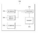
본 발명에 따른, 무선 통신 시스템에서, DMRS (Demodulation Reference Signal)를 전송하는 단말에 있어서, 기지국과 무선 신호를 송수신하는 RF 모듈; 및 상기 RF 모듈과 연결되어, 상향링크 데이터를 위한 자원 영역 내의 적어도 하나의 OFDM 심볼에 상기 DMRS 신호를 맵핑하여 전송하는 프로세서를 포함하되, 상기 적어도 하나의 OFDM 심볼에서, 상기 DMRS 신호가 맵핑되지 않은 자원 요소는, 상기 상향링크 데이터를 위해 사용되지 않을 수 있다.In a wireless communication system according to the present invention, a terminal for transmitting a Demodulation Reference Signal (DMRS) includes an RF module for transmitting and receiving a radio signal to and from a base station; And a processor coupled to the RF module for mapping and transmitting the DMRS signal to at least one OFDM symbol in a resource region for uplink data, wherein in the at least one OFDM symbol, the DMRS signal is not mapped The resource element may not be used for the uplink data.
이 때, 상기 DMRS 신호는, 상기 DFT-S-OFDM 방식 또는 CP-OFDM 방식을 적용하여 전송할 수 있다.At this time, the DMRS signal can be transmitted by applying the DFT-S-OFDM scheme or the CP-OFDM scheme.
또한, 상기 DFT-S-OFDM 방식이 적용되는 경우와 상기 CP-OFDM 방식이 적용되는 경우의 DMRS 맵핑 패턴은 동일할 수 있다.In addition, the DMRS mapping pattern in the case of applying the DFT-S-OFDM scheme and the case of applying the CP-OFDM scheme may be the same.
또한, 상기 DMRS는 상기 적어도 하나의 OFDM심볼에 기 설정된 부반송파 간격으로 맵핑될 수 있다.Also, the DMRS may be mapped to the at least one OFDM symbol at a predetermined subcarrier interval.
또한, 상기 DFT-S-OFDM 방식이 적용되는 경우와 상기 CP-OFDM 방식이 적용되는 경우의 DMRS 시퀀스는 서로 다른 타입의 시퀀스에 기반하여 생성될 수 있다.In addition, the DMRS sequence in the case of applying the DFT-S-OFDM scheme and in the case of applying the CP-OFDM scheme may be generated based on different types of sequences.
또한, 상기 DFT-S-OFDM 방식이 적용되는 경우와 상기 CP-OFDM 방식이 적용되는 경우의 DMRS의 맵핑 위치는 서로 상이할 수 있다.Also, the mapping positions of the DFT-S-OFDM scheme and the DMRS scheme of the CP-OFDM scheme may be different from each other.
또한, 상향링크 데이터를 전송하기 위한 자원 블록 그룹의 크기에 관한 정보를 수신하고, 상기 수신한 자원 블록 그룹의 크기를 기반으로, 상기 DMRS가 맵핑되지 않는 OFDM 심볼을 통해 전송되는 상향링크 데이터를 전송할 수 있다.In addition, the mobile station receives information on the size of a resource block group for transmitting uplink data, and transmits uplink data transmitted through an OFDM symbol to which the DMRS is not mapped, based on the size of the received resource block group .
또한, 상기 RF 모듈을 통해, 적어도 하나의 OFDM 심볼에서 상향링크 데이터 전송을 위해 사용되지 않는 자원 요소에 관한 제어 정보를 수신하고, 상기 제어 정보를 기반으로, 상기 DMRS 신호가 맵핑되지 않은 자원 요소에 상기 상향링크 데이터를 맵핑하지 않을 수 있다.In addition, it is also possible to receive control information on a resource element not used for uplink data transmission in at least one OFDM symbol through the RF module, and to transmit the DMRS signal to a resource element The uplink data may not be mapped.
본 발명에 따르면, 참조 신호의 오버헤드 및 MIMO 이득에 따라, 참조 신호가 전송되는 심볼 내의 데이터 배치를 상이하게 함으로써, 효율적으로 신호를 전송할 수 있다.According to the present invention, it is possible to efficiently transmit a signal by making the data arrangement in the symbol to which the reference signal is transmitted different according to the overhead of the reference signal and the MIMO gain.
본 발명에서 얻을 수 있는 효과는 이상에서 언급한 효과들로 제한되지 않으며, 언급하지 않은 또 다른 효과들은 아래의 기재로부터 본 발명이 속하는 기술분야에서 통상의 지식을 가진 자에게 명확하게 이해될 수 있을 것이다.The effects obtained by the present invention are not limited to the above-mentioned effects, and other effects not mentioned can be clearly understood by those skilled in the art from the following description will be.
도 1은 무선 통신 시스템의 일례로서 E-UMTS 망구조를 개략적으로 도시한 도면.
도 2는 3GPP 무선 접속망 규격을 기반으로 한 단말과 E-UTRAN 사이의 무선 인터페이스 프로토콜(Radio Interface Protocol)의 제어평면(Control Plane) 및 사용자평면(User Plane) 구조를 나타내는 도면.
도 3은 3GPP 시스템에 이용되는 물리 채널들 및 이들을 이용한 일반적인 신호 송신 방법을 설명하기 위한 도면.
도 4는 LTE 시스템에서 사용되는 무선 프레임의 구조를 예시하는 도면.
도 5는 LTE 시스템에서 사용되는 하향링크 무선 프레임의 구조를 예시하는 도면.
도 6은 LTE 시스템에서 사용되는 상향링크 서브프레임의 구조를 도시하는 도면.
도 7 및 도 8은 4개의 안테나를 이용한 하향링크 전송을 지원하는 LTE 시스템에서의 하향링크 참조 신호의 구조를 도시하는 도면이다.
도 9는 현재 3GPP 표준문서에서 정의하고 있는 하향링크 DM-RS 할당 예를 도시한다.
도 10은 TXRU와 안테나 엘리먼트의 연결 방식의 일례들을 나타낸다.
도 11은 Self-contained 서브프레임 구조의 일 예이다.
도 12 및 도 13은 Self-contained 서브프레임 구조에서 기본 DMRS와 추가 DMRS를 전송하는 일 예이다.
도 14 및 도 15는 하향링크 데이터 및 상향링크 데이터를 위한 DMRS 전송의 일례이다.
도 16은 채널 상태 변화 측정을 위한 참조 신호 전송의 일례이다.
도 17은 제어 채널과 데이터 채널에서 참조 신호를 공유하는 일례를 설명하기 위한 도면이다.
도 18 내지 도 19는 상이한 길이를 가지는 OFDM 심볼들이 멀리플렉싱 되는 실시 예를 설명하기 위한 도면이다.
도 20은 부반송파 간격에 따른, 하나의 심볼 내에서의 RE를 구성하는 예시를 설명하기 위한 도면이다.
도 21은 본 발명의 일 실시예에 따라 DMRS를 CDM 방식으로 N개 RE에 스프레딩하고, 8개의 직교 코드를 이용하여 전송하는 방법을 설명하기 위한 도면이다.
도 22는 본 발명의 일 실시예에 따라 FDM과 CDM을 조합하여 사용하는 방법을 설명하기 위한 도면이다.
도 23은 본 발명의 일 실시예에 따라 FDM과 OCC를 조합하여 사용하는 방법을 설명하기 위한 도면이다.
도 24는 본 발명의 다른 일 실시예에 따라 FDM과 CDM을 조합하여 사용하는 방법을 설명하기 위한 도면이다.
도 25 및 26은 본 발명의 다른 일 실시예에 따라 FDM과 OCC를 조합하여 사용하는 방법을 설명하기 위한 도면이다.
도 27은 본 발명의 다른 일 실시예에 따라 FDM을 이용하고 AP당 8 RE 간격을 설명하는 방법을 설명하기 위한 도면이다.
도 28은 본 발명의 일 실시예에 따라 FDM과 CDM을 적용하는 방안을 도시한 도면이다.
도 29는 본 발명의 일 실시예에 따른 통신 장치의 블록 구성도를 예시한다.1 schematically shows an E-UMTS network structure as an example of a wireless communication system.
2 is a diagram showing a control plane and a user plane structure of a radio interface protocol between a UE and an E-UTRAN based on the 3GPP radio access network standard;
3 is a view for explaining a physical channel used in a 3GPP system and a general signal transmission method using the same.
4 is a diagram illustrating a structure of a radio frame used in an LTE system;
5 is a diagram illustrating a structure of a downlink radio frame used in an LTE system;
6 is a diagram illustrating a structure of an uplink subframe used in an LTE system;
FIGS. 7 and 8 are diagrams illustrating a structure of a DL reference signal in an LTE system supporting downlink transmission using four antennas. Referring to FIG.
FIG. 9 shows an example of downlink DM-RS allocation defined in the current 3GPP standards document.
10 shows an example of a connection method of the TXRU and the antenna element.
11 is an example of a self-contained subframe structure.
12 and 13 show an example of transmitting a basic DMRS and an additional DMRS in a self-contained subframe structure.
14 and 15 show an example of DMRS transmission for downlink data and uplink data.
16 is an example of a reference signal transmission for measuring a channel state change.
17 is a diagram for explaining an example of sharing a reference signal in a control channel and a data channel.
FIGS. 18 to 19 are diagrams for explaining an embodiment in which OFDM symbols having different lengths are far-multiplexed.
FIG. 20 is a diagram for explaining an example of constructing an RE in one symbol according to a subcarrier interval. FIG.
FIG. 21 is a diagram for explaining a method of spreading the DMRS in N REs according to the CDM scheme and transmitting the DMRSs using 8 orthogonal codes according to an embodiment of the present invention.
22 is a diagram for explaining a method of using FDM and CDM in combination according to an embodiment of the present invention.
23 is a diagram for explaining a method of using FDM and OCC in combination according to an embodiment of the present invention.
24 is a diagram for explaining a method of using FDM and CDM in combination according to another embodiment of the present invention.
25 and 26 are views for explaining a method of using FDM and OCC in combination according to another embodiment of the present invention.
FIG. 27 is a diagram for explaining a method of using FDM according to another embodiment of the present invention and explaining 8 RE intervals per AP. FIG.
28 is a diagram illustrating a method of applying FDM and CDM according to an embodiment of the present invention.
29 illustrates a block diagram of a communication apparatus according to an embodiment of the present invention.
이하에서 첨부된 도면을 참조하여 설명된 본 발명의 실시예들에 의해 본 발명의 구성, 작용 및 다른 특징들이 용이하게 이해될 수 있을 것이다. 이하에서 설명되는 실시예들은 본 발명의 기술적 특징들이 3GPP 시스템에 적용된 예들이다.Hereinafter, the structure, operation and other features of the present invention will be readily understood by the embodiments of the present invention described with reference to the accompanying drawings. The embodiments described below are examples in which technical features of the present invention are applied to a 3GPP system.
본 명세서는 LTE 시스템 및 LTE-A 시스템을 사용하여 본 발명의 실시예를 설명하지만, 이는 예시로서 본 발명의 실시예는 상기 정의에 해당되는 어떤 통신 시스템에도 적용될 수 있다.Although the present specification describes an embodiment of the present invention using an LTE system and an LTE-A system, embodiments of the present invention may be applied to any communication system corresponding to the above definition.
또한, 본 명세서는 기지국의 명칭은 RRH(remote radio head), eNB, TP(transmission point), RP(reception point), 중계기(relay) 등을 포함하는 포괄적인 용어로 사용될 수 있다.Also, the present invention can be used in a generic term including a remote radio head (RRH), an eNB, a transmission point (TP), a reception point (RP), a relay and the like.
도 2는 3GPP 무선 접속망 규격을 기반으로 한 단말과 E-UTRAN 사이의 무선 인터페이스 프로토콜(Radio Interface Protocol)의 제어평면(Control Plane) 및 사용자평면(User Plane) 구조를 나타내는 도면이다. 제어평면은 단말(User Equipment; UE)과 네트워크가 호를 관리하기 위해서 이용하는 제어 메시지들이 송신되는 통로를 의미한다. 사용자평면은 애플리케이션 계층에서 생성된 데이터, 예를 들어, 음성 데이터 또는 인터넷 패킷 데이터 등이 송신되는 통로를 의미한다.2 is a diagram showing a control plane and a user plane structure of a radio interface protocol between a UE and an E-UTRAN based on the 3GPP radio access network standard. The control plane refers to a path through which control messages used by a UE and a network are transmitted. The user plane means a path through which data generated in the application layer, for example, voice data or Internet packet data, is transmitted.
제1계층인 물리계층은 물리채널(Physical Channel)을 이용하여 상위 계층에게 정보 송신 서비스(Information Transfer Service)를 제공한다. 물리계층은 상위에 있는 매체접속제어(Medium Access Control) 계층과는 송신채널(Trans포트 Channel)을 통해 연결되어 있다. 상기 송신채널을 통해 매체접속제어 계층과 물리계층 사이에 데이터가 이동한다. 송신측과 수신측의 물리계층 사이는 물리채널을 통해 데이터가 이동한다. 상기 물리채널은 시간과 주파수를 무선 자원으로 활용한다. 구체적으로, 물리채널은 하향링크에서 OFDMA(Orthogonal Frequency Division Multiple Access) 방식으로 변조되고, 상향링크에서 SC-FDMA(Single Carrier Frequency Division Multiple Access) 방식으로 변조된다.The physical layer, which is the first layer, provides an information transfer service to an upper layer using a physical channel. The physical layer is connected to the upper Medium Access Control layer through a transmission channel (Trans Port Channel). Data moves between the MAC layer and the physical layer over the transmission channel. Data is transferred between the transmitting side and the receiving side physical layer through the physical channel. The physical channel utilizes time and frequency as radio resources. Specifically, the physical channel is modulated in an OFDMA (Orthogonal Frequency Division Multiple Access) scheme in a downlink, and is modulated in an SC-FDMA (Single Carrier Frequency Division Multiple Access) scheme in an uplink.
제2계층의 매체접속제어(Medium Access Control; MAC) 계층은 논리채널(Logical Channel)을 통해 상위계층인 무선링크제어(Radio Link Control; RLC) 계층에 서비스를 제공한다. 제2계층의 RLC 계층은 신뢰성 있는 데이터 송신을 지원한다. RLC 계층의 기능은 MAC 내부의 기능 블록으로 구현될 수도 있다. 제2계층의 PDCP(Packet Data Convergence Protocol) 계층은 대역폭이 좁은 무선 인터페이스에서 IPv4나 IPv6와 같은 IP 패킷을 효율적으로 송신하기 위해 불필요한 제어정보를 줄여주는 헤더 압축(Header Compression) 기능을 수행한다.The Medium Access Control (MAC) layer of the second layer provides a service to a radio link control (RLC) layer, which is an upper layer, through a logical channel. The RLC layer of the second layer supports reliable data transmission. The function of the RLC layer may be implemented as a functional block in the MAC. The Packet Data Convergence Protocol (PDCP) layer of the second layer performs a header compression function to reduce unnecessary control information in order to efficiently transmit IP packets such as IPv4 and IPv6 in a wireless interface with a narrow bandwidth.
제3계층의 최하부에 위치한 무선 자원제어(Radio Resource Control; RRC) 계층은 제어평면에서만 정의된다. RRC 계층은 무선베어러(Radio Bearer)들의 설정(Configuration), 재설정(Re-configuration) 및 해제(Release)와 관련되어 논리채널, 송신채널 및 물리채널들의 제어를 담당한다. 무선 베어러는 단말과 네트워크 간의 데이터 전달을 위해 제2계층에 의해 제공되는 서비스를 의미한다. 이를 위해, 단말과 네트워크의 RRC 계층은 서로 RRC 메시지를 교환한다. 단말과 네트워크의 RRC 계층 사이에 RRC 연결(RRC Connected)이 있을 경우, 단말은 RRC 연결 상태(Connected Mode)에 있게 되고, 그렇지 못할 경우 RRC 휴지 상태(Idle Mode)에 있게 된다. RRC 계층의 상위에 있는 NAS(Non-Access Stratum) 계층은 세션 관리(Session Management)와 이동성 관리(Mobility Management) 등의 기능을 수행한다.The Radio Resource Control (RRC) layer located at the bottom of the third layer is defined only in the control plane. The RRC layer is responsible for the control of the logical channels, the transmission channels and the physical channels in connection with the configuration, re-configuration and release of radio bearers. The radio bearer refers to a service provided by the second layer for data transmission between the UE and the network. To this end, the terminal and the RRC layer of the network exchange RRC messages with each other. If there is an RRC connection (RRC Connected) between the UE and the RRC layer of the network, the UE is in the RRC Connected Mode, otherwise it is in the RRC Idle Mode. The Non-Access Stratum (NAS) layer at the top of the RRC layer performs functions such as session management and mobility management.
네트워크에서 단말로 데이터를 송신하는 하향 송신채널은 시스템 정보를 송신하는 BCH(Broadcast Channel), 페이징 메시지를 송신하는 PCH(Paging Channel), 사용자 트래픽이나 제어 메시지를 송신하는 하향 SCH(Shared Channel) 등이 있다. 하향 멀티캐스트 또는 방송 서비스의 트래픽 또는 제어 메시지의 경우 하향 SCH를 통해 송신될 수도 있고, 또는 별도의 하향 MCH(Multicast Channel)을 통해 송신될 수도 있다. 한편, 단말에서 네트워크로 데이터를 송신하는 상향 송신채널로는 초기 제어 메시지를 송신하는 RACH(Random Access Channel), 사용자 트래픽이나 제어 메시지를 송신하는 상향 SCH(Shared Channel)가 있다. 송신채널의 상위에 있으며, 송신채널에 매핑되는 논리채널(Logical Channel)로는 BCCH(Broadcast Control Channel), PCCH(Paging Control Channel), CCCH(Common Control Channel), MCCH(Multicast Control Channel), MTCH(Multicast Traffic Channel) 등이 있다.A downlink transmission channel for transmitting data from a network to a terminal includes a BCH (Broadcast Channel) for transmitting system information, a PCH (Paging Channel) for transmitting a paging message, a downlink SCH (Shared Channel) for transmitting user traffic and control messages, have. In the case of a traffic or control message of a downlink multicast or broadcast service, it may be transmitted through a downlink SCH, or may be transmitted via a separate downlink multicast channel (MCH). Meanwhile, the uplink transmission channel for transmitting data from the UE to the network includes RACH (Random Access Channel) for transmitting an initial control message and an uplink SCH (Shared Channel) for transmitting user traffic or control messages. A logical channel mapped to a transmission channel is a Broadcast Control Channel (BCCH), a Paging Control Channel (PCCH), a Common Control Channel (CCCH), a Multicast Control Channel (MCCH) Traffic Channel).
도 3은 3GPP 시스템에 이용되는 물리 채널들 및 이들을 이용한 일반적인 신호 송신 방법을 설명하기 위한 도면이다.3 is a diagram for explaining a physical channel used in a 3GPP system and a general signal transmission method using the same.
단말은 전원이 켜지거나 새로이 셀에 진입한 경우 기지국과 동기를 맞추는 등의 초기 셀 탐색(Initial cell search) 작업을 수행한다(S301). 이를 위해, 단말은 기지국으로부터 주 동기 채널(Primary Synchronization Channel; P-SCH) 및 부 동기 채널(Secondary Synchronization Channel; S-SCH)을 수신하여 기지국과 동기를 맞추고, 셀 ID 등의 정보를 획득할 수 있다. 그 후, 단말은 기지국으로부터 물리 방송 채널(Physical Broadcast Channel)를 수신하여 셀 내 방송 정보를 획득할 수 있다. 한편, 단말은 초기 셀 탐색 단계에서 하향링크 참조 신호(Downlink Reference Signal; DL RS)를 수신하여 하향링크 채널 상태를 확인할 수 있다.When the terminal is turned on or newly enters a cell, the terminal performs an initial cell search operation such as synchronizing with the base station (S301). To this end, the terminal receives a primary synchronization channel (P-SCH) and a secondary synchronization channel (S-SCH) from a base station and synchronizes with the base station and acquires information such as a cell ID have. Then, the terminal can receive the physical broadcast channel from the base station and acquire the in-cell broadcast information. Meanwhile, the UE can receive the downlink reference signal (DL RS) in the initial cell search step to check the downlink channel state.
초기 셀 탐색을 마친 단말은 물리 하향링크 제어 채널(Physical Downlink Control Channel; PDCCH) 및 상기 PDCCH에 실린 정보에 따라 물리 하향링크 공유 채널(Physical Downlink Control Channel; PDSCH)을 수신함으로써 좀더 구체적인 시스템 정보를 획득할 수 있다(S302).Upon completion of the initial cell search, the UE receives more detailed system information by receiving a Physical Downlink Control Channel (PDCCH) and a Physical Downlink Control Channel (PDSCH) according to the information on the PDCCH (S302).
한편, 기지국에 최초로 접속하거나 신호 송신을 위한 무선 자원이 없는 경우 단말은 기지국에 대해 임의 접속 과정(Random Access Procedure; RACH)을 수행할 수 있다(단계 S303 내지 단계 S306). 이를 위해, 단말은 물리 임의 접속 채널(Physical Random Access Channel; PRACH)을 통해 특정 시퀀스를 프리앰블로 송신하고(S303 및 S305), PDCCH 및 대응하는 PDSCH를 통해 프리앰블에 대한 응답 메시지를 수신할 수 있다(S304 및 S306). 경쟁 기반 RACH의 경우, 추가적으로 충돌 해결 절차(Contention Resolution Procedure)를 수행할 수 있다.Meanwhile, if there is no radio resource for the first time access to the base station or for signal transmission, the mobile station can perform a random access procedure (RACH) on the base station (steps S303 to S306). To this end, the UE transmits a specific sequence through a Physical Random Access Channel (PRACH) (S303 and S305), and receives a response message for the preamble on the PDCCH and the corresponding PDSCH ( S304 and S306). In case of the contention-based RACH, a contention resolution procedure can be additionally performed.
상술한 바와 같은 절차를 수행한 단말은 이후 일반적인 상/하향링크 신호 송신 절차로서 PDCCH/PDSCH 수신(S307) 및 물리 상향링크 공유 채널(Physical Uplink Shared Channel; PUSCH)/물리 상향링크 제어 채널(Physical Uplink Control Channel; PUCCH) 송신(S308)을 수행할 수 있다. 특히 단말은 PDCCH를 통하여 하향링크 제어 정보(Downlink Control Information; DCI)를 수신한다. 여기서 DCI는 단말에 대한 자원 할당 정보와 같은 제어 정보를 포함하며, 그 사용 목적에 따라 포맷이 서로 다르다.The UE having performed the procedure described above transmits PDCCH / PDSCH (S307) and Physical Uplink Shared Channel (PUSCH) / Physical Uplink Control Channel Control Channel (PUCCH) transmission (S308). In particular, the UE receives downlink control information (DCI) through the PDCCH. Here, the DCI includes control information such as resource allocation information for the UE, and formats are different according to the purpose of use.
한편, 단말이 상향링크를 통해 기지국에 송신하는 또는 단말이 기지국으로부터 수신하는 제어 정보는 하향링크/상향링크 ACK/NACK 신호, CQI(Channel Quality Indicator), PMI(Precoding Matrix 인덱스), RI(Rank Indicator) 등을 포함한다. 3GPP LTE 시스템의 경우, 단말은 상술한 CQI/PMI/RI 등의 제어 정보를 PUSCH 및/또는 PUCCH를 통해 송신할 수 있다.Meanwhile, the control information transmitted by the UE to the Node B via the uplink or received from the Node B by the UE includes a downlink / uplink ACK / NACK signal, a channel quality indicator (CQI), a precoding matrix index (PMI) ) And the like. In the case of the 3GPP LTE system, the UE can transmit control information such as CQI / PMI / RI as described above through PUSCH and / or PUCCH.
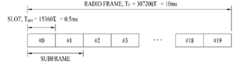
도 4는 LTE 시스템에서 사용되는 무선 프레임의 구조를 예시하는 도면이다.4 is a diagram illustrating a structure of a radio frame used in an LTE system.
도 4를 참조하면, 무선 프레임(radio frame)은 10ms(327200×?Ts)의 길이를 가지며 10개의 균등한 크기의 서브프레임(subframe)으로 구성되어 있다. 각각의 서브프레임은 1ms의 길이를 가지며 2개의 슬롯(slot)으로 구성되어 있다. 각각의 슬롯은 0.5ms(15360×Ts)의 길이를 가진다. 여기에서, Ts 는 샘플링 시간을 나타내고, Ts=1/(15kHz×2048)=3.2552×10-8(약 33ns)로 표시된다. 슬롯은 시간 영역에서 복수의 OFDM 심볼을 포함하고, 주파수 영역에서 복수의 자원블록(Resource Block; RB)을 포함한다. LTE 시스템에서 하나의 자원블록은 12개의 부반송파×7(6)개의 OFDM 심볼을 포함한다. 데이터가 송신되는 단위시간인 TTI(Transmission Time Interval)는 하나 이상의 서브프레임 단위로 정해질 수 있다. 상술한 무선 프레임의 구조는 예시에 불과하고, 무선 프레임에 포함되는 서브프레임의 수 또는 서브프레임에 포함되는 슬롯의 수, 슬롯에 포함되는 OFDM 심볼의 수는 다양하게 변경될 수 있다.4, the radio frame (radio frame) is composed of 10ms (327200 ×? Ts) subframes (subframe) of a size having a length of 10 equivalents. Each subframe has a length of 1 ms and is composed of two slots. Each slot has a length of 0.5 ms (15360 x Ts ). Here, Ts represents the sampling time, and is represented by Ts = 1 / (15 kHz x 2048) = 3.2552 x 10⁻⁸ (about 33 ns). A slot includes a plurality of OFDM symbols in a time domain and a plurality of resource blocks (RB) in a frequency domain. In the LTE system, one resource block includes 12 subcarriers x 7 (6) OFDM symbols. A transmission time interval (TTI), which is a unit time at which data is transmitted, may be defined in units of one or more subframes. The structure of the radio frame is merely an example, and the number of subframes included in a radio frame, the number of slots included in a subframe, and the number of OFDM symbols included in a slot can be variously changed.
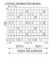
도 5는 하향링크 무선 프레임에서 하나의 서브프레임의 제어 영역에 포함되는 제어 채널을 예시하는 도면이다.5 is a diagram illustrating a control channel included in a control region of one subframe in a downlink radio frame.
도 5를 참조하면, 서브프레임은 14개의 OFDM 심볼로 구성되어 있다. 서브프레임 설정에 따라 처음 1 내지 3개의 OFDM 심볼은 제어 영역으로 사용되고 나머지 13~11개의 OFDM 심볼은 데이터 영역으로 사용된다. 도면에서 R1 내지 R4는 안테나 0 내지 3에 대한 기준 신호(Reference Signal(RS) 또는 Pilot Signal)를 나타낸다. RS는 제어 영역 및 데이터 영역과 상관없이 서브프레임 내에 일정한 패턴으로 고정된다. 제어 채널은 제어 영역 중에서 RS가 할당되지 않은 자원에 할당되고, 트래픽 채널도 데이터 영역 중에서 RS가 할당되지 않은 자원에 할당된다. 제어 영역에 할당되는 제어 채널로는 PCFICH(Physical Control Format Indicator CHannel), PHICH(Physical Hybrid-ARQ Indicator CHannel), PDCCH(Physical Downlink Control CHannel) 등이 있다.Referring to FIG. 5, a subframe is composed of 14 OFDM symbols. According to the subframe setting, the first to third OFDM symbols are used as a control region and the remaining 13 to 11 OFDM symbols are used as a data region. In the figure, R1 to R4 represent a reference signal (RS) or pilot signal for
PCFICH는 물리 제어 포맷 지시자 채널로서 매 서브프레임 마다 PDCCH에 사용되는 OFDM 심볼의 개수를 단말에게 알려준다. PCFICH는 첫 번째 OFDM 심볼에 위치하며 PHICH 및 PDCCH에 우선하여 설정된다. PCFICH는 4개의 REG(Resource Element Group)로 구성되고, 각각의 REG는 셀 ID(Cell IDentity)에 기초하여 제어 영역 내에 분산된다. 하나의 REG는 4개의 RE(Resource Element)로 구성된다. RE는 하나의 부반송파×하나의 OFDM 심볼로 정의되는 최소 물리 자원을 나타낸다. PCFICH 값은 대역폭에 따라 1 내지 3 또는 2 내지 4의 값을 지시하며 QPSK(Quadrature Phase Shift Keying)로 변조된다.The PCFICH informs the UE of the number of OFDM symbols used in the PDCCH for each subframe as a physical control format indicator channel. The PCFICH is located in the first OFDM symbol and is set prior to the PHICH and PDCCH. The PCFICH is composed of four REGs (Resource Element Groups), and each REG is distributed in the control area based on the cell ID (Cell IDentity). One REG is composed of four REs (Resource Elements). RE denotes a minimum physical resource defined by one subcarrier x one OFDM symbol. The PCFICH value indicates a value of 1 to 3 or 2 to 4 depending on the bandwidth and is modulated by Quadrature Phase Shift Keying (QPSK).
PHICH는 물리 HARQ(Hybrid - Automatic Repeat and request) 지시자 채널로서 상향링크 송신에 대한 HARQ ACK/NACK을 나르는데 사용된다. 즉, PHICH는 UL HARQ를 위한 DL ACK/NACK 정보가 송신되는 채널을 나타낸다. PHICH는 1개의 REG로 구성되고, 셀 특정(cell-specific)하게 스크램블(scrambling) 된다. ACK/NACK은 1 비트로 지시되며, BPSK(Binary phase shift keying)로 변조된다. 변조된 ACK/NACK은 확산인자(Spreading Factor; SF) = 2 또는 4로 확산된다. 동일한 자원에 매핑되는 복수의 PHICH는 PHICH 그룹을 구성한다. PHICH 그룹에 다중화되는 PHICH의 개수는 확산 코드의 개수에 따라 결정된다. PHICH (그룹)은 주파수 영역 및/또는 시간 영역에서 다이버시티 이득을 얻기 위해 3번 반복(repetition)된다.The PHICH is used as a physical HARQ (Hybrid Automatic Repeat and Request) indicator channel to carry HARQ ACK / NACK for uplink transmission. That is, the PHICH indicates a channel through which DL ACK / NACK information for UL HARQ is transmitted. The PHICH consists of one REG and is cell-specific scrambled. The ACK / NACK is indicated by 1 bit and is modulated by BPSK (Binary Phase Shift Keying). The modulated ACK / NACK is spread with a spreading factor (SF) = 2 or 4. A plurality of PHICHs mapped to the same resource constitute a PHICH group. The number of PHICHs multiplexed into the PHICH group is determined by the number of spreading codes. The PHICH (group) is repetitized three times to obtain the diversity gain in the frequency domain and / or the time domain.
PDCCH는 물리 하향링크 제어 채널로서 서브프레임의 처음 n개의 OFDM 심볼에 할당된다. 여기에서, n은 1 이상의 정수로서 PCFICH에 의해 지시된다. PDCCH는 하나 이상의 CCE로 구성된다. PDCCH는 송신 채널인 PCH(Paging channel) 및 DL-SCH(Downlink-shared channel)의 자원할당과 관련된 정보, 상향링크 스케줄링 그랜트(Uplink Scheduling Grant), HARQ 정보 등을 각 단말 또는 단말 그룹에게 알려준다. PCH(Paging channel) 및 DL-SCH(Downlink-shared channel)는 PDSCH를 통해 송신된다. 따라서, 기지국과 단말은 일반적으로 특정한 제어 정보 또는 특정한 서비스 데이터를 제외하고는 PDSCH를 통해서 데이터를 각각 송신 및 수신한다.The PDCCH is allocated to the first n OFDM symbols of the subframe as the physical downlink control channel. Here, n is an integer of 1 or more and is indicated by the PCFICH. The PDCCH consists of one or more CCEs. The PDCCH notifies each terminal or group of terminals of information related to resource allocation of a paging channel (PCH) and a downlink-shared channel (DL-SCH), an uplink scheduling grant, and HARQ information. A paging channel (PCH) and a downlink-shared channel (DL-SCH) are transmitted on the PDSCH. Therefore, the BS and the MS generally transmit and receive data via the PDSCH, except for specific control information or specific service data.
PDSCH의 데이터가 어떤 단말(하나 또는 복수의 단말)에게 송신되는 것이며, 상기 단말들이 어떻게 PDSCH 데이터를 수신하고 디코딩(decoding)을 해야 하는 지에 대한 정보 등은 PDCCH에 포함되어 송신된다. 예를 들어, 특정 PDCCH가 "A"라는 RNTI(Radio Network Temporary Identity)로 CRC 마스킹(masking)되어 있고, "B"라는 무선자원(예, 주파수 위치) 및 "C"라는 DCI 포맷 즉, 송신 형식 정보(예, 송신 블록 사이즈, 변조 방식, 코딩 정보 등)를 이용해 송신되는 데이터에 관한 정보가 특정 서브프레임을 통해 송신된다고 가정한다. 이 경우, 셀 내의 단말은 자신이 가지고 있는 RNTI 정보를 이용하여 검색 영역에서 PDCCH를 모니터링, 즉 블라인드 디코딩하고, "A" RNTI를 가지고 있는 하나 이상의 단말이 있다면, 상기 단말들은 PDCCH를 수신하고, 수신한 PDCCH의 정보를 통해 "B"와 "C"에 의해 지시되는 PDSCH를 수신한다.PDSCH data is transmitted to a terminal (one or a plurality of terminals), and information on how the terminals receive and decode PDSCH data is included in the PDCCH and transmitted. For example, if a particular PDCCH is CRC masked with an RNTI (Radio Network Temporary Identity) of " A ", a DCI format of radio resource (e.g., frequency location) It is assumed that information on data to be transmitted using information (e.g., transmission block size, modulation scheme, coding information, etc.) is transmitted through a specific subframe. In this case, the UE in the cell monitors and blind decodes the PDCCH in the search area using the RNTI information it has, and if there is more than one UE having the " A " RNTI, the UEs receive the PDCCH, And receives the PDSCH indicated by " B " and " C " through the information of one PDCCH.
도 6은 LTE 시스템에서 사용되는 상향링크 서브프레임의 구조를 도시하는 도면이다.6 is a diagram illustrating a structure of an uplink subframe used in an LTE system.
도 6을 참조하면, 상향링크 서브프레임은 제어정보를 나르는 PUCCH(Physical Uplink Control CHannel)가 할당되는 영역과 사용자 데이터를 나르는 PUSCH(Physical Uplink Shared CHannel)가 할당되는 영역으로 나눌 수 있다. 서브프레임의 중간 부분이 PUSCH에 할당되고, 주파수 영역에서 데이터 영역의 양측 부분이 PUCCH에 할당된다. PUCCH 상에 송신되는 제어정보는 HARQ에 사용되는 ACK/NACK, 하향링크 채널 상태를 나타내는 CQI(Channel Quality Indicator), MIMO를 위한 RI(Rank Indicator), 상향링크 자원 할당 요청인 SR(Scheduling Request) 등이 있다. 한 단말에 대한 PUCCH는 서브프레임 내의 각 슬롯에서 서로 다른 주파수를 차지하는 하나의 자원블록을 사용한다. 즉, PUCCH에 할당되는 2개의 자원블록은 슬롯 경계에서 주파수 호핑(frequency hopping)된다. 특히 도 6은 m=0인 PUCCH, m=1인 PUCCH, m=2인 PUCCH, m=3인 PUCCH가 서브프레임에 할당되는 것을 예시한다.Referring to FIG. 6, the uplink subframe can be divided into a region to which a Physical Uplink Control CHannel (PUCCH) for carrying control information and a PUSCH (Physical Uplink Shared CHannel) to transmit user data are allocated. An intermediate portion of the subframe is allocated to the PUSCH, and both side portions of the data region in the frequency domain are allocated to the PUCCH. The control information transmitted on the PUCCH includes an ACK / NACK used for HARQ, a channel quality indicator (CQI) indicating a downlink channel state, a rank indicator (RI) for MIMO, a scheduling request (SR) . The PUCCH for one UE uses one resource block occupying different frequencies in each slot in a subframe. That is, the two resource blocks allocated to the PUCCH are frequency hopped at the slot boundary. In particular, FIG. 6 illustrates that a PUCCH with m = 0, a PUCCH with m = 1, a PUCCH with m = 2, and a PUCCH with m = 3 are allocated to a subframe.
이하에서는, 참조 신호에 관하여 보다 상세히 설명한다.Hereinafter, the reference signal will be described in more detail.
일반적으로 채널 측정을 위하여 데이터와 함께 송신측과 수신측 모두가 이미 알고 있는 참조 신호가 송신측에서 수신측으로 전송된다. 이러한 참조 신호는 채널 측정뿐만 아니라 변조 기법을 알려주어 복조 과정이 수행되도록 하는 역할을 수행한다. 참조 신호는 기지국과 특정 단말을 위한 전용 참조 신호(dedicated RS; DRS), 즉 단말 특정 참조 신호와 셀 내 모든 단말을 위한 셀 특정 참조 신호인 공통 참조 신호(common RS 또는 Cell specific RS; CRS)로 구분된다. 또한, 셀 특정 참조 신호는 단말에서 CQI/PMI/RI 를 측정하여 기지국으로 보고하기 위한 참조 신호를 포함하며, 이를 CSI-RS(Channel State Information-RS)라고 지칭한다.In general, a reference signal already known by the transmitting side and the receiving side together with data is transmitted from the transmitting side to the receiving side for channel measurement. The reference signal not only informs the channel measurement but also the modulation technique, thereby performing the demodulation process. A reference signal is a dedicated RS (DRS) for a Node B and a UE, that is, a common RS or a cell specific RS (CRS), which is a UE-specific reference signal and a cell- Respectively. In addition, the cell specific reference signal includes a reference signal for measuring CQI / PMI / RI at the UE and reporting the CQI / PMI / RI to the Node B, which is referred to as CSI-RS (Channel State Information-RS).
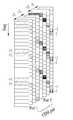
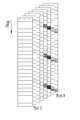
도 7 및 도 8은 4개의 안테나를 이용한 하향링크 전송을 지원하는 LTE 시스템에서의 참조 신호의 구조를 도시하는 도면이다. 특히 도 8은 일반(normal) 순환 전치(Cyclic Prefix)인 경우를 도시하며, 도 9는 확장(extended) 순환 전치인 경우를 도시한다.7 and 8 are diagrams showing a structure of a reference signal in an LTE system supporting downlink transmission using four antennas. Particularly, FIG. 8 shows a case of a normal cyclic prefix, and FIG. 9 shows a case of an extended cyclic prefix.
도 7 및 도 8을 참조하면, 격자에 기재된 0 내지 3은 안테나 포트 0 내지 3 각각에 대응하여 채널 측정과 데이터 복조를 위하여 송신되는 셀 특정 참조 신호인 CRS(Common Reference Signal)를 의미하며, 상기 셀 특정 참조 신호인 CRS는 데이터 정보 영역뿐만 아니라 제어 정보 영역 전반에 걸쳐 단말로 전송될 수 있다.Referring to FIGS. 7 and 8,
또한, 격자에 기재된 'D'는 단말 특정 RS인 하향링크 DM-RS(Demodulation-RS)를 의미하고, DM-RS는 데이터 영역 즉, PDSCH를 통하여 단일 안테나 포트 전송을 지원한다. 단말은 상위 계층을 통하여 상기 단말 특정 RS인 DM-RS의 존재 여부를 시그널링 받는다. 도 7 및 도 8은 안테나 포트 5에 대응하는 DM-RS를 예시하며, 3GPP 표준문서 36.211에서는 안테나 포트 7 내지 14, 즉 총 8개의 안테나 포트에 대한 DM-RS 역시 정의하고 있다.The 'D' in the grid means a downlink DM-RS (Demodulation-RS) which is a UE-specific RS, and the DM-RS supports a single antenna port transmission through a data area, i.e., PDSCH. The MS receives a signal indicating whether the DM-RS serving as the UE-specific RS exists through an upper layer. 7 and 8 illustrate a DM-RS corresponding to the
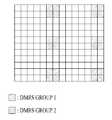
도 9는 현재 3GPP 표준문서에서 정의하고 있는 하향링크 DM-RS 할당 예를 도시한다.FIG. 9 shows an example of downlink DM-RS allocation defined in the current 3GPP standards document.
도 9를 참조하면, DM-RS 그룹 1에는 안테나 포트 {7, 8, 11, 13}에 해당하는 DM-RS가 안테나 포트 별 시퀀스를 이용하여 맵핑되며, DM-RS 그룹 2에는 안테나 포트 {9, 10, 12, 14}에 해당하는 DM-RS가 마찬가지로 안테나 포트 별 시퀀스를 이용하여 맵핑된다.Referring to FIG. 9, the DM-RS corresponding to the antenna ports {7, 8, 11, 13} is mapped to the DM-
이하, 채널 상태 정보(channel state information, CSI) 보고에 관하여 설명한다. 현재 LTE 표준에서는 채널 상태 정보 없이 운용되는 개루프(open-loop) MIMO와 채널 상태 정보에 기반하여 운용되는 폐루프(closed-loop) MIMO 두 가지 송신 방식이 존재한다. 특히, 폐루프 MIMO 에서는 MIMO 안테나의 다중화 이득(다중화 gain)을 얻기 위해 기지국 및 단말 각각은 채널 상태 정보를 바탕으로 빔포밍을 수행할 수 있다. 기지국은 채널 상태 정보를 단말로부터 얻기 위해, 단말에게 PUCCH(Physical Uplink Control CHannel) 또는 PUSCH(Physical Uplink Shared CHannel)를 할당하여 하향링크 신호에 대한채널 상태 정보(CSI)를 피드백 하도록 명령한다.Hereinafter, channel state information (CSI) reporting will be described. Currently, there are two open-loop MIMOs that operate without channel state information and closed-loop MIMOs that operate based on channel state information. Particularly, in the closed loop MIMO, each of the base station and the UE can perform beamforming based on the channel state information in order to obtain the multiplexing gain (multiplexing gain) of the MIMO antenna. The BS allocates a Physical Uplink Control Channel (PUCCH) or a Physical Uplink Shared CHannel (PUSCH) to the UE to acquire channel state information from the UE, and instructs the Node B to feedback CSI on the downlink signal.
CSI는 RI(Rank Indicator), PMI(Precoding Matrix 인덱스), CQI(Channel Quality Indication) 세가지 정보로 크게 분류된다. 우선, RI는 상술한 바와 같이 채널의 랭크 정보를 나타내며, 단말이 동일 주파수-시간 자원을 통해 수신할 수 있는 스트림의 개수를 의미한다. 또한, RI는 채널의 롱텀 페이딩(long term fading)에 의해 결정되므로 PMI, CQI 값 보다 통상 더 긴 주기로 기지국으로 피드백 된다.CSI is classified into three categories: RI (Rank Indicator), PMI (Precision Matrix Index), and CQI (Channel Quality Indication). First, RI represents rank information of a channel as described above, and it means the number of streams that the terminal can receive through the same frequency-time resource. Also, since the RI is determined by long term fading of the channel, it is fed back to the base station at a period longer than the PMI and the CQI value.
두 번째로, PMI는 채널의 공간 특성을 반영한 값으로 SINR 등의 메트릭(metric)을 기준으로 단말이 선호하는 기지국의 프리코딩 행렬 인덱스를 나타낸다. 마지막으로, CQI는 채널의 세기를 나타내는 값으로 통상 기지국이 PMI를 이용했을 때 얻을 수 있는 수신 SINR을 의미한다.Second, the PMI is a value reflecting the spatial characteristics of the channel, and represents a precoding matrix index of a base station preferred by the UE based on a metric such as SINR. Finally, the CQI is a value indicating the strength of a channel, which means a reception SINR that can be obtained when a base station normally uses PMI.
3GPP LTE-A 시스템에서 기지국은 다수의 CSI 프로세스를 UE에게 설정하고, 각 CSI 프로세스에 대한 CSI를 보고 받을 수 있다. 여기서 CSI 프로세스는 기지국으로부터의 신호 품질 특정을 위한 CSI-RS 자원과 간섭 측정을 위한 CSI-IM (interference measurement) 자원, 즉 IMR (interference measurement resource)로 구성된다.In the 3GPP LTE-A system, a base station can set up a plurality of CSI processes to UEs and report CSI for each CSI process. Here, the CSI process consists of a CSI-RS resource for signal quality specification from a base station and an interference measurement resource (IMR) for interference measurement.
Millimeter Wave (mmW)에서는 파장이 짧아져서 동일 면적에 다수개의 안테나 엘리먼트의 설치가 가능하다. 구체적으로, 30GHz 대역에서 파장은 1cm로써 4 by 4 cm의 패널(panel)에 0.5 lambda(파장) 간격으로 2D (dimension) 배열 형태인 총 64(8x8)의 안테나 엘리먼트 설치가 가능하다. 그러므로 mmW 분야에서의 최근 동향에서는 다수개의 안테나 엘리먼트를 사용하여 BF (beamforming) 이득을 높여 커버리지를 증가시키거나, 쓰루풋 (throughput)의 증대를 시도하고 있다.In Millimeter Wave (mmW), the wavelength is shortened so that multiple antenna elements can be installed in the same area. Specifically, in a 30 GHz band, a total of 64 (8 × 8) antenna elements can be installed in a dimension of 0.5 lambda (wavelength) intervals on a panel of 4 by 4 cm with a wavelength of 1 cm. Therefore, in recent trends in the field of mmW, several antenna elements are used to increase the BF (beamforming) gain to increase the coverage or to increase the throughput.
이 경우에 안테나 엘리먼트 별로 송신 파워 및 위상 조절이 가능하도록 TXRU (Transceiver Unit)을 구비한다면, 주파수 자원 별로 독립적인 빔포밍이 가능하다. 그러나 100여개의 안테나 엘리먼트 모두에 TXRU를 설치하기에는 가격측면에서 실효성이 떨어지는 문제를 갖게 된다. 그러므로 하나의 TXRU에 다수개의 안테나 엘리먼트를 매핑하고 아날로그 위상 천이기 (analog phase shifter)로 빔의 방향을 조절하는 방식이 고려되고 있다. 이러한 아날로그 빔포밍 방식은 전 대역에 있어서 하나의 빔 방향만을 만들 수 있어 주파수 선택적 빔포밍을 해줄 수 없는 단점을 갖는다.In this case, if TXRU (Transceiver Unit) is provided so that transmission power and phase can be adjusted for each antenna element, independent beam forming can be performed for each frequency resource. However, installing a TXRU on all 100 antenna elements has a problem in terms of cost effectiveness. Therefore, a method of mapping a plurality of antenna elements to one TXRU and adjusting the direction of the beam by an analog phase shifter is considered. Such an analog beamforming method has a disadvantage in that it can make only one beam direction in all bands and can not perform frequency selective beamforming.
디지털 BF와 아날로그 BF의 중간 형태로 Q개의 안테나 엘리먼트보다 적은 개수인 B개의 TXRU를 갖는 hybrid BF를 고려할 수 있다. 이 경우에 B개의 TXRU와 Q개의 안테나 엘리먼트의 연결 방식에 따라서 차이는 있지만, 동시에 송신할 수 있는 빔 방향은 B개 이하로 제한되게 된다.A hybrid BF with B TXRUs that are fewer than Q antenna elements in the middle of digital BF and analog BF can be considered. In this case, although there is a difference depending on the connection method of B TXRU and Q antenna elements, the number of beam directions that can be transmitted at the same time is limited to B or less.
도 10은 TXRU와 안테나 엘리먼트의 연결 방식의 일례들을 나타낸다.10 shows an example of a connection method of the TXRU and the antenna element.
도 10의 (a)은 TXRU가 서브-어레이(sub-array)에 연결된 방식을 나타낸다. 이 경우에 안테나 엘리먼트는 하나의 TXRU에만 연결된다. 이와 달리 도 10의 (b)는 TXRU가 모든 안테나 엘리먼트에 연결된 방식을 나타낸다. 이 경우에 안테나 엘리먼트는 모든 TXRU에 연결된다. 도 10에서 W는 아날로그 위상 천이기에 의해 곱해지는 위상 벡터를 나타낸다. 즉, W에 의해 아날로그 빔포밍의 방향이 결정된다. 여기서 CSI-RS 안테나 포트와 TXRU들과의 매핑은 1-to-1 또는 1-to-多 일 수 있다.Figure 10 (a) shows how the TXRU is connected to a sub-array. In this case, the antenna element is connected to only one TXRU. 10 (b) shows how the TXRU is connected to all the antenna elements. In this case, the antenna element is connected to all TXRUs. 10, W represents a phase vector multiplied by an analog phase shifter. That is, the direction of the analog beam forming is determined by W. Here, the mapping between the CSI-RS antenna port and the TXRUs may be 1-to-1 or 1-to-many.
더욱 많은 통신 기기들이 더욱 큰 통신 용량을 요구하게 됨에 따라 기존의 RAT (radio access technology)에 비해 향상된 무선 광대역 통신에 대한 필요성이 대두되고 있다. 또한 다수의 기기 및 사물들을 연결하여 언제 어디서나 다양한 서비스를 제공하는 메시브 (massive) MTC (Machine Type Communications) 역시 차세대 통신에서 고려될 주요 이슈 중 하나이다. 뿐만 아니라 신뢰도 (reliability) 및 레이턴시 (latency)에 민감한 서비스/UE를 고려한 통신 시스템 디자인이 논의되고 있다. 이러한 점을 고려한 차세대 RAT의 도입이 논의되고 있으며, 본 발명에서는 편의상 NewRAT (이하, NR)이라고 지칭한다.As more and more communication devices require greater communication capacity, there is a need for improved wireless broadband communication over existing RAT (radio access technology). Massive MTC (Machine Type Communications), which provides various services by connecting multiple devices and objects, is also one of the major issues to be considered in the next generation communication. In addition, a communication system design considering a service / UE sensitive to reliability and latency is being discussed. The introduction of the next generation RAT in consideration of this point is being discussed and is referred to as NewRAT (hereinafter, NR) for the sake of convenience in the present invention.
TDD 시스템에서 데이터 송신 레이턴시를 최소화하기 위하여 5세대 NR 에서는 도 11과 같은 self-contained 서브프레임 구조를 고려하고 있다. 도 11은 Self-contained 서브프레임 구조의 일 예이다.In order to minimize the data transmission latency in the TDD system, the self-contained subframe structure shown in FIG. 11 is considered in the fifth generation NR. 11 is an example of a self-contained subframe structure.
도 11에서 빗금 영역은 하향링크 제어 영역을 나타내고, 검정색 부분은 상향링크 제어 영역을 나타낸다. 표시가 없는 영역은 하향링크 데이터 송신을 위해 사용될 수도 있고, 상향링크 데이터 송신을 위해 사용될 수도 있다. 이러한 구조의 특징은 한 개의 서브프레임 내에서 하향링크 송신과 상향링크 송신이 순차적으로 진행되어, 서브프레임 내에서 하향링크 데이터를 보내고, 상향링크 ACK/NACK도 받을 수 있다. 결과적으로 데이터 송신 에러 발생시에 데이터 재송신까지 걸리는 시간을 줄이게 되며, 이로 인해 최종 데이터 전달의 레이턴시를 최소화할 수 있다.11, the hatched area indicates a downlink control area, and the black part indicates an uplink control area. The unmarked area may be used for downlink data transmission or for uplink data transmission. This structure is characterized in that downlink transmission and uplink transmission sequentially proceed in one subframe, so that downlink data can be transmitted in a subframe and uplink ACK / NACK can be received. As a result, it is possible to reduce the time taken to retransmit data when a data transmission error occurs, thereby minimizing the latency of final data transmission.
이러한 self-contained 서브프레임 구조에서 기지국과 UE가 송신 모드에서 수신모드로 전환 과정 또는 수신모드에서 송신모드로 전환 과정을 위한 시간 간극 (time gap)이 필요하다. 이를 위하여 self-contained 서브프레임 구조에서 하향링크에서 상향링크로 전환되는 시점의 일부 OFDM 심볼 (OFDM 심볼; OS)이 GP (guard period)로 설정되게 된다.In this self-contained subframe structure, a time gap is required between the base station and the UE for the transition from the transmit mode to the receive mode or from the receive mode to the transmit mode. For this purpose, some OFDM symbols (OFDM symbol: OS) at the time of switching from the downlink to the uplink in the self-contained subframe structure are set as the guard period (GP).
NR 을 기반으로 동작하는 시스템에서 구성/설정 가능한 상기 self-contained 서브프레임 타입의 일례로, 적어도 다음과 같은 4가지 서브프레임 타입을 고려할 수 있다.As an example of the self-contained subframe type that can be configured / settable in the NR-based system, at least the following four types of subframe can be considered.
- 하향링크 제어 구간 + 하향링크 데이터 구간 + GP + 상향링크 제어 구간- DL control interval + DL data interval + GP + UL control interval
- 하향링크 제어 구간 + 하향링크 데이터 구간- DL control interval + downlink data interval
- 하향링크 제어 구간 + GP + 상향링크 데이터 구간 + 상향링크 제어 구간- DL control interval + GP + UL data interval + UL control interval
- 하향링크 제어 구간 + GP + 상향링크 데이터 구간- DL control interval + GP + UL data interval
한편, 5세대 NR에서는 NR 시스템의 특징 상, DMRS 전송에 아래와 같은 문제점이 발생할 수 있다. 첫째로, NR 시스템의 설계 요구 사항은, 주파수 대역이 700MHz부터 70GHz까지로 설정되고, 시스템 대역폭이 5MHz부터 1GHz까지로 설정되며, 이동 속도는 0km/h에서 500km/h까지의 속도에서 통신이 가능해야 하고, 실내/외 및 큰 셀 등에서도 통신이 가능하도록 설계되어야 하는 바, NR 시스템의 설계 요구사항이 상당히 광범위한 측면이 있다.On the other hand, in the fifth generation NR, the following problems may occur in transmission of the DMRS due to the characteristics of the NR system. First, the design requirements of the NR system are that the frequency band is set from 700 MHz to 70 GHz, the system bandwidth is set from 5 MHz to 1 GHz, and the movement speed is from 0 km / h to 500 km / h The design requirements of the NR system have a wide range of aspects, as it must be designed to communicate both indoors / outdoors and large cells.
따라서, 이러한 광범위한 설계 사항을 모두 만족 시키기 위한, DMRS의 배치 방법이 필요한데, 극단적인 환경을 가정하여 단일 패턴으로 NR DMRS를 설계하는 경우, 자원 효율측면에서 상당히 비효율적일 수 있다. 반면에, 다양한 패턴의 NR DMRS를 설계한다면, 실제 구현이 복잡하게 되는 문제점이 발생한다.Therefore, a method of arranging DMRS is required to satisfy all of these wide range of design requirements. If NR DMRS is designed in a single pattern assuming an extreme environment, it may be considerably inefficient in terms of resource efficiency. On the other hand, if NR DMRS of various patterns is designed, the actual implementation becomes complicated.
두번째로, 초기에 데이터를 디코딩 하기 위한 목적과 셀 간 간섭을 측정 및 제거하기 위한 목적에 따라, NR 시스템의 DMRS는 데이터 채널의 시작 부분에 위치하게 된다. 이러한 경우, 도플러 정도가 높거나, SNR이 낮은 경우 등의 채널 상황에서, 서브프레임의 앞 부분에 있는 DMRS를 사용하는 경우, 채널 추정 성능이 떨어 질 수 있다.Second, for the purpose of initially decoding data and for the purpose of measuring and removing inter-cell interference, the DMRS of the NR system is located at the beginning of the data channel. In this case, the channel estimation performance may be degraded when the DMRS in the front part of the subframe is used in a channel situation such as a high Doppler degree or a low SNR.
세번째로, LTE-A에서는 단일 사용자당 전송 받을 수 있는 레이어의 수가 8레이어였으나, NR에서 대규모(Massive) MIMO의 도움으로 단일 사용자당 전송 받을 수 있는 레이어의 수가 16레이어 이상으로 늘어날 수 있다. 따라서, DMRS 안테나 포트 구분을 위해서 직교 자원을 구성할 필요한성이 있는데, 레이어 수가 증가하면, 참조 신호(RS) 오버헤드가 증가하고, 따라서, 많은 수의 레이어를 구분하기 위한 효율적인 직교 자원 구성 방법 필요하게 된다.Third, in LTE-A, the number of layers that can be transmitted per single user was eight, but with the help of massive MIMO in NR, the number of layers that can be transmitted per single user can be increased to more than 16 layers. Therefore, there is a need to construct an orthogonal resource for DMRS antenna port classification. If the number of layers increases, the overhead of the RS increases, and therefore, an efficient orthogonal resource configuration method is required to distinguish a large number of layers .
네번째로, NR에서는 고주파수 대역을 사용하기 때문에 경로손실이 심하게 나타나게 되는데, 이를 극복하기 위하여 NR 에서 빔포밍을 도입하는 것이 논의되고 있다. 즉, 4GHz 대역의 기지국에서는 상향링크에서 아날로그 수신 빔포밍을 활용하는 등의 아날로그 빔포밍을 도입할 가능성이 높으며, 6GHz 이상 대역에서는 기지국과 단말에서의 아날로그 빔포밍을 도입 가능성이 높아지고 있다.Fourth, since NR uses a high frequency band, path loss becomes severe. To overcome this problem, introduction of beamforming in NR is being discussed. That is, in a 4 GHz band base station, there is a high possibility of introducing analog beamforming such as utilizing analog receive beamforming in the uplink, and in the 6 GHz or higher band, the possibility of introducing analog beamforming in the base station and the terminal is increasing.
기존 전방위적(Omni Direction)으로 신호를 송수신할 때 지연 확산과 도플러 확산의 양상이 아날로그 빔포밍 적용 시 다르게 나타날 수 있다. 예들 들어, 전방위적 으로 신호를 수신할 때 도플러 확산이 크게 나타나고, 속도가 증가하면, 코히런트 시간이 감소된다. 이 때, 아날로그 수신 빔포밍이 도입되면, 특정 방향으로 수신되는 신호의 도플러 주파수만 수신되어, 도플러 확산은 상대적으로 작게 되고, 이에 따라 코히런트 시간이 증가된다. 이러한 경우, 이동 속도가 높은 경우를 위해 추가로 적용된 DMRS는 불필요한 오버헤드가 될 수 있는 문제점이 발생한다.The delay spread and Doppler spread patterns can be different when analog beamforming is applied when transmitting and receiving signals in the conventional Omni Direction. For example, the Doppler spread is large when receiving a signal in all directions, and the coherent time is reduced when the speed is increased. At this time, when the analog receive beamforming is introduced, only the Doppler frequency of the signal received in a specific direction is received, and the Doppler spread becomes relatively small, and thus the coherent time is increased. In this case, there is a problem that the DMRS, which is additionally applied to the case where the moving speed is high, may become unnecessary overhead.
본 발명에서는, 상술한 문제점을 해결하기 위하여, DMRS의 배치 방법 및 기존의 DMRS 이외의 추가 참조 신호를 정의하고, 이러한 추가 참조 신호의 배치 및 전송 방법에 대해 제안하고자 한다.In order to solve the above-mentioned problems, the present invention defines a method of arranging DMRSs and additional reference signals other than the existing DMRSs, and proposes a method of arranging and transmitting such additional reference signals.
본 발명의 본격적인 설명에 앞서, 본 발명에서 기존 참조 신호는 기본 DMRS, 필수(Fundamental) DM-RS 등으로 명명할 수 있고, 추가되는 참조 신호는 추가(Additional) 참조 신호, 고품질 (High quality) 참조 신호, 하이-퍼포먼스(High performance) 참조 신호, 보충적 (Supplemental) DM-RS, 부 (Secondary) DM-RS, 애드-온(Add-on) DMRS 등과 같이 표현될 수 있다.Prior to the description of the present invention, an existing reference signal may be referred to as a basic DMRS, a fundamental DM-RS, or the like, and the added reference signal may be referred to as an additional reference signal, a high quality reference A high performance reference signal, a supplemental DM-RS, a secondary DM-RS, an add-on DMRS, and the like.
<기본 DMRS와 추가 DMRS의 위치><Location of basic DMRS and additional DMRS>
본 발명에 따르면, NR의 DMRS는 서브프레임 데이터 영역의 앞부분에 위치하는 기본 참조 신호(즉, 기본 DMRS)와 서브프레임의 데이터 영역 중에 전송되는 추가 참조 신호(즉, 추가 DMRS)로 구성된다.According to the present invention, the DMRS of NR consists of a basic reference signal (i.e., the basic DMRS) located in the front of the subframe data area and an additional reference signal (i.e., additional DMRS) transmitted in the data area of the subframe.
기본 DMRS는 하향링크, 상향링크, 스페셜 링크 등의 링크, 부반송파 간격(subcarrier spacing), OFDM 심볼 간격(OFDM symbol duration) 등의 뉴머롤로지(Numerology), 전송 레이어, 단말이 실내/외 중, 어디에 위치하는 지 등의 배치 시나리오, 단말의 이동 속도, 전송 블록의 크기 등에 관계 없이 항상 전송되는 참조 신호를 말한다.The basic DMRS includes a link such as a downlink, an uplink, a special link, a subcarrier spacing, a numerical data such as an OFDM symbol duration, a transmission layer, A moving speed of a terminal, a size of a transmission block, and the like.
NR에서 기본 DMRS는 서브프레임 데이터 영역의 앞 부분에 위치한다. NR에서, 데이터의 초기 디코딩이 설계 시, 중요한 요구사항이 되는데, DMRS를 데이터 신호에 앞서 보냄으로써, 데이터 디코딩을 위해서 필수적으로 요구되는 채널 추정 정보를 빠르게 획득할 수 있다.The basic DMRS in NR is located in the front part of the subframe data area. In NR, the initial decoding of data is an important requirement in design. By sending the DMRS ahead of the data signal, the channel estimation information required for data decoding can be obtained quickly.
한편, NR에서의 프레임 구조는 하향링크, 상향링크, 스페셜 링크가 공통으로 사용되는 것을 목적으로 설계된다. 따라서, 인접 셀 또는 인접 링크에서 들어오는 간섭 신호의 채널을 추정하기 위해, 하향링크, 상향링크, 스페셜 링크의 DMRS 위치를 서브프레임 내에서 일치 시키는 것을 고려할 수 있다.On the other hand, the frame structure in NR is designed for the purpose that the downlink, uplink, and special link are commonly used. Therefore, in order to estimate the channel of the interference signal coming from the adjacent cell or the adjacent link, it may be considered to match the DMRS positions of the downlink, uplink and special links in the subframe.
NR에서 고려하는 서브프레임 구조에 있어서 하향링크 데이터 영역과 상향링크 데이터 영역의 시작점은 하향링크 제어 영역의 길이 및 혜의 존재에 따라 달라 질 수 있는데, 예를 들어, 제어 채널이 전송되는 첫 번째 OFDM 심볼에 이어서 하향링크 데이터가 전송된다면, 두 번째 OFDM 심볼부터 데이터 영역이 시작될 수도 있고, 제어 채널이 전송되는 첫 번째 OFDM 심볼에 이어서 상향링크 데이터가 전송되는 경우에는 두 번째 OFDM 심볼이 GP로 사용되고, 세 번째 OFDM 심볼부터 데이터가 시작될 수 있다.In the subframe structure considered in NR, the starting point of the downlink data region and the uplink data region may be different according to the length of the downlink control region and the presence of the downlink control region. For example, when the first OFDM If the downlink data is transmitted following the symbol, the data area may be started from the second OFDM symbol. If uplink data is transmitted following the first OFDM symbol to which the control channel is transmitted, the second OFDM symbol is used as the GP, Data can be started from the third OFDM symbol.
이와 같이 하향링크 데이터와 상향링크 데이터의 시작점이 달라 질 수도 있기 때문에, 도 12에서 보는 것과 같이, 기본 DMRS는 하향링크 데이터와 상향링크 데이터 영역에서 공통적으로 데이터 전송에 사용되는 OFDM 심볼 중, 첫 심볼에 배치하는 것이 바람직하다.As shown in FIG. 12, since the starting point of the downlink data and the uplink data may be different from each other, the basic DMRS uses the first symbol of the OFDM symbol, which is commonly used for data transmission in the downlink data and the uplink data area, As shown in Fig.
한편, 제어 영역의 OFDM 심볼 길이와 데이터 영역의 OFDM 심볼 길이가 달라 질 수 있는데, 이러한 경우에도, 도 13에서 볼 수 있듯이, 하향링크 제어 채널과 GP가 차지하는 OFDM 심볼 이후의 하향링크 데이터 영역과 상향링크 데이터 영역에서 공통적으로 데이터 전송을 위해 사용되는 OFDM 심볼 중, 첫 번째 OFDM 심볼에 기본 DMRS를 배치할 수 있다.13, the OFDM symbol length of the control region and the OFDM symbol length of the data region may be different from each other. In this case as well, the downlink data region after the OFDM symbol occupied by the downlink control channel and the GP, The basic DMRS can be arranged in the first OFDM symbol among the OFDM symbols commonly used for data transmission in the link data region.
한편, 추가 DMRS는 데이터 영역의 특정 위치에 위치할 수 있는데, 아래와 같이 2가지 유형으로 나누어 볼 수 있다.On the other hand, the additional DMRS can be located at a specific position in the data area, and can be divided into two types as shown below.
추가 DMRS 유형 1은 자원 요소 중 일부를 사용할 수 있고, 추가DMRS 유형 2는 한 OFDM symbol 전체를 사용할 수 있다.
추가 DMRS 유형 1의 경우에는, 추가 DMRS를 다음과 같이 배치할 수 있다.For the
1. 실시 예 1-11. Example 1-1
추가 DMRS는 추가 DMRS를 위한 자원 요소의 개수에 따라서, 레벨 단위로 구분하고, 전송 환경에 따라서, 추가 DMRS를 위한 자원 요소의 개수, 즉, 추가DMRS의 레벨을 조정하도록 한다. 이 때, 다중 추가 DMRS 레벨 중에서 하나는 기본 DMRS만 전송되는 경우에 해당하도록 한다. 대표적으로, 추가 DMRS의 레벨이 0인 경우, 기본 DMRS만 전송될 수 있다.The additional DMRS is divided into levels according to the number of resource elements for additional DMRS, and the number of resource elements for additional DMRS, that is, the level of additional DMRS, is adjusted according to the transmission environment. At this time, one of the multiple additional DMRS levels corresponds to the case where only the basic DMRS is transmitted. Typically, if the level of the additional DMRS is zero, only the basic DMRS can be transmitted.
2. 실시 예 1-22. Examples 1-2
자원 요소 단위의 추가 DMRS는 하나의 자원 블록 안에서 균등한 간격으로 배치될 수 있다. 일반적으로, 자원 요소 단위의 추가 DMRS는 기본 DMRS에 정의된 안테나 포트와 동일한 수의 안테나 포트가 정의되지만, 자원 요소 단위의 추가DMRS를 사용하여 OFDM 심볼 사이의 위상 변화량을 측정하는 것을 목적으로 하거나, 또는, 모든 안테나 포트들에서 위상 변화량이 유사한 경우처럼 특별한 케이스인 경우에는, 기본 DMRS에 정의된 안테나 포트보다 적은 수의 안테나 포트의 추가 DMRS만 정의할 수 있다.Additional DMRSs on a resource element basis may be placed at even intervals within a resource block. In general, the additional DMRS per resource element is defined as the same number of antenna ports as the antenna port defined in the basic DMRS, but it is also possible to use an additional DMRS per resource element to measure the amount of phase shift between OFDM symbols, Or, in special cases, such as when the phase variation is similar at all antenna ports, only the additional DMRS of the antenna port defined in the basic DMRS can be defined.
한편, 추가 DMRS 유형 2의 경우에는, 추가 DMRS를 다음과 같이 배치할 수 있다.On the other hand, in the case of the
1. 실시 예 1-11. Example 1-1
OFDM 심볼 단위로 추가 DMRS가 사용되는 경우, 추가 DMRS의 위치는 기본 DMRS로 사용되는 OFDM 심볼 이후에 있는 OFDM 심볼의 수와 추가DMRS로 사용되는 OFDM 심볼 이후에 있는 OFDM 심볼의 수가 서로 비슷하게 되는 곳에 배치할 수 있다. 예를 들어, 데이터 영역에 12개 OFDM 심볼이 있고 기본 DRMS는 2번째 OFDM 심볼에 위치하는 경우, 추가 DMRS는 7 번째 OFDM 심볼에 배치된다. 다른 예로, 데이터 영역에 12개 OFDM 심볼이 있고 기본 DRMS와 2개의 추가 DRMS가 있는 경우, 1, 5, 9번째 OFDM 심볼에 각각 기본 DMRS와 추가 DRMS를 배치시키면 각 DMRS이후에 있는 OFDM 심볼의 개수는 유사한 수준이 된다. 이는 DMRS가 채널 추정 변화를 잘 반영할 수 있도록 하는 장점이 있다.When an additional DMRS is used in the OFDM symbol unit, the position of the additional DMRS is arranged such that the number of OFDM symbols after the OFDM symbol used as the basic DMRS and the number of OFDM symbols after the OFDM symbol used by the additional DMRS are similar to each other can do. For example, if there are 12 OFDM symbols in the data area and the base DRMS is located in the 2nd OFDM symbol, the additional DMRS is allocated to the 7th OFDM symbol. As another example, if there are 12 OFDM symbols in the data area and there are a basic DRMS and two additional DRMSs, if the basic DMRS and the additional DRMS are allocated to the 1st, 5th and 9th OFDM symbols, respectively, then the number of OFDM symbols after each DMRS Becomes a similar level. This has the advantage that the DMRS can better reflect the channel estimation change.
2. 실시 예 1-22. Examples 1-2
OFDM 심볼 단위로 추가 DMRS가 사용되는 경우, 추가 DMRS의 위치는 기본 DMRS로 사용되는 OFDM 심볼과 연속한 OFDM 심볼에 배치될 수 있다. 예를 들어, 기본 DMRS이 2번째 OFDM 심볼에 위치하는 경우, 추가 DMRS는 3번째 OFDM 심볼에 배치된다. 이는 다중 안테나 전송에서 안테나의 수를 확장하거나, 동시 전송되는 사용자를 확장하기 위한 목적으로 DMRS의 자원을 증가 시키는 장점이 있다.If an additional DMRS is used in OFDM symbol units, the position of the additional DMRS may be placed in OFDM symbols used in the basic DMRS and consecutive OFDM symbols. For example, if the primary DMRS is located in the second OFDM symbol, the additional DMRS is placed in the third OFDM symbol. This has the advantage of increasing the number of antennas in the multi-antenna transmission or increasing the resources of the DMRS for the purpose of extending the concurrent users.
<DMRS의 밀도(Density)를 가변 하는 방법><Method of varying the density of DMRS>
DMRS의 밀도를 가변 시키는 첫번째 방법으로, 기존 참조 신호를 유지하고 추가 참조 신호를 온-디맨드(on-demand) 방식에 따라 추가하는 방식이 있다. 예를 들어, 도플러가 심해지거나, 지연 확산이 심해지는 경우, 또는 MCS (Modulation and Coding Scheme)레벨에 따라, High MCS에서 추가 참조 신호를 추가할 수 있다.As a first method of varying the density of the DMRS, there is a method of maintaining an existing reference signal and adding an additional reference signal according to an on-demand method. For example, an additional reference signal can be added at the High MCS, depending on whether the Doppler becomes worse, the delay spread becomes worse, or the Modulation and Coding Scheme (MCS) level.
DMRS의 밀도를 가변 시키는 두번째 방법으로, 수신단의 성능에 따라 DMRS 밀도의 가변을 허용하는 사용자에게는 온-디맨드(On-demand)방식으로 참조 신호를 더 보내거나 덜 보내는 등의 가변성을 둘 수 있다. 예를 들어, 아날로그 빔포밍이 가능한 수신단인 경우, 전방위적 수신을 가정한 참조 신호 송신에 대해서 온-디맨드(on-demand)방식에 따라. 참조 신호를 덜 보낼 것을 요청하는 방식이다.As a second method of varying the density of the DMRS, a user who permits the variation of the DMRS density according to the performance of the receiving end can be provided with a variability such as sending an on-demand reference signal or sending the reference signal less. For example, in the case of a receiver capable of analog beamforming, on-demand transmission of reference signal transmission assuming omni-directional reception is possible. And to send less reference signals.
세번째 방법으로는, 페이징, 임의 접속 응답(Random Access Response), 시스템 정보 등을 보내는 채널에서는 참조 신호의 밀도를 고정하고, 특정 단말에게 정보를 보내는 채널에서는 참조 신호 밀도를 가변할 수 있다.As a third method, the density of the reference signal can be fixed in a channel for sending paging, random access response, system information, etc., and the reference signal density can be varied in a channel for sending information to a specific terminal.
네번째 방법으로는, 채널 디코딩을 위한 승인(grant) 메시지를 통해, 참조 신호 밀도 제어 정보를 정의한다. 그리고 상기 참조 신호 밀도 제어 정보에는, 다음과 같은 정보가 포함될 수 있다.In a fourth method, reference signal density control information is defined through a grant message for channel decoding. The reference signal density control information may include the following information.
- 현재 전송된 채널 또는 앞으로 전송할 채널에서 사용된 참조 신호 밀도에 대한 정보 (예들 들면, 기본 밀도(Default density)의 사용 여부, 기본 밀도에 비해 밀도가 어느 정도 증감했는지에 대한 정보 등)- information on the density of the reference signal used in the currently transmitted channel or the channel to be transmitted in the future (for example, whether or not the default density is used, information about how much the density is increased or decreased compared to the basic density)
- 추가(Additional) DMRS 레벨 정보- Additional DMRS level information
- 추가 DMRS 유형에 대한 정보- Information on additional DMRS types
- 채널의 변화량 보고를 위한 트리거링 메시지- Triggering message for channel change reporting
다섯번째 방법으로는, CSI-RS를 이용한 단말의 숏-텀 측정, 수행 후 CSI 보고와 함께, 시간 및 주파수의 채널 변화량을 보고할 수 있다. 채널 변화량 보고는 참조 신호 밀도의 가변 여부를 결정하는 지표가 될 수 있다. 또한 단말은 참조 신호 밀도 가변 요청 메시지를 전송할 수도 있다.As a fifth method, the short-term measurement of the terminal using the CSI-RS, the CSI report after the execution, and the channel change amount of the time and frequency can be reported. The channel change amount report can be an index for determining whether the reference signal density is variable or not. The UE may also transmit a reference signal density variable request message.
여섯번째 방법으로는, 단말이 CSI를 보고하는 경우, 선호하는 추가 DMRS 레벨 정보를 함께 보고하도록 한다. 상기 선호하는 추가 DMRS 레벨(preferred additional DMRS level)은, 상기 CSI 보고에 포함된 CQI에 해당하는 MCS의 PDSCH를 수신할 경우, 최적의 쓰루풋(throughput)을 얻을 수 있도록 해주는 추가 DMRS 레벨에 해당한다. 이 때, 단말은 CSI 계산시에 추가 DMRS의 레벨에 따라 추가되는 DM-RS 자원 요소의 오버헤드를 반영하여, CSI를 계산하도록 한다.As a sixth method, when the terminal reports the CSI, report the preferred additional DMRS level information together. The preferred additional DMRS level corresponds to an additional DMRS level that allows optimal throughput to be obtained when a PDSCH of the MCS corresponding to the CQI included in the CSI report is received. At this time, the terminal reflects the overhead of the DM-RS resource element added according to the level of the additional DMRS in the CSI calculation, and calculates the CSI.
일곱번째 방법으로는, 전송 레이어가 증가하는 경우, 기존 참조 신호에 추가 참조 신호를 추가할 수 있다.In the seventh method, when the transmission layer increases, an additional reference signal can be added to the existing reference signal.
또한, 공통 제어 채널(Common control channel) 혹은 공통 제어 메시지(common control message)에서 지시된 데이터 영역에서는 기본 DMRS와 함께 추가 DMRS가 기본적으로 배치될 수 있다.Further, in the data area indicated by the common control channel or the common control message, an additional DMRS can be basically arranged along with the basic DMRS.
그리고, 단말 특정 제어 채널(UE specific control channel) 혹은 단말 특정 제어 메시지(UE specific control message)로 데이터가 지시될 때는, 서브프레임 내에 DMRS 밀도를 가변적으로 운용할 수 있다. 이를 위해, 제어 메시지에 DMRS 관련 지시자를 설정할 수 있다. 즉, PDSCH, PUSCH에 대한 DMRS 밀도를 제어 메시지를 통해 지시할 수 있다. 한편, 상기 DMRS 관련 지시자가 설정되는 제어 메시지는 DCI에 포함되어 단말에 전송되거나, RRC 시그널링을 통해 단말에 전송될 수 있다. 이 때, DCI 포맷에 따라, 상기 제어 메시지의 포함여부를 달리하거나, 제어 메시지가 포함되는 형태가 변동될 수 있다. 또한, 아날로그 수신 빔포밍을 수행하는 단말은 DMRS 밀도 변경을 요청함으로써, DMRS 밀도를 기지국 단에서 변경할 수도 있다.When data is indicated by a UE specific control channel or a UE specific control message, the DMRS density can be variably operated in the subframe. For this purpose, a DMRS-related indicator can be set in the control message. That is, the DMRS density for the PDSCH and the PUSCH can be indicated through the control message. Meanwhile, the control message in which the DMRS-related indicator is set may be included in the DCI and transmitted to the UE or may be transmitted to the UE through RRC signaling. At this time, depending on the DCI format, whether the control message is included or not, or the form in which the control message is included may be changed. In addition, the terminal performing the analog receive beamforming may change the DMRS density at the base station side by requesting the DMRS density change.
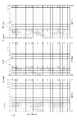
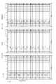
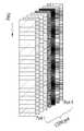
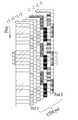
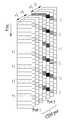
도 14 및 도 15는 본 발명에 따른, DMRS 전송의 일 예시를 나타낸다. 즉, 도 14 및 도 15는 앞서 정의한 추가 DMRS 유형 2를 오버헤드에 따라, 레벨 0과 레벨 1로 구분하고, 각 레벨에 따라, DMRS를 전송하는 실시 예를 나타낸다.Figures 14 and 15 illustrate one example of a DMRS transmission, in accordance with the present invention. That is, FIGS. 14 and 15 show an embodiment in which the
도 14 및 도 15를 참조하면, 추가 DMRS 유형 2의 레벨에 따라, 상향링크 전송 영역 또는 하향링크 전송 영역에서의 DMRS 위치를 일치시킬 수 있다. 레벨 1은 오버헤드를 증가시키는 경우로, 높은 랭크(Higher rank) 전송 또는 낮은 랭크(lower rank) 전송 시, 채널 추정 성능을 향상 시키는 목적으로 적용할 수 있다. 또한, 레벨 0은 낮은 참조 신호 오버헤드를 갖는 낮은 랭크(Lower Rank) 전송을 목적으로 한다.Referring to FIGS. 14 and 15, it is possible to match the DMRS positions in the uplink transmission region or the downlink transmission region according to the level of the
또 다른 예로서, 도 14 및 도 15에서, "A. Level 1(Higher Rank)"는 낮은 랭크 전송 시, 채널 추정 성능을 향상 시키는 목적으로 사용될 수 있고, "B. Level 1 (Lower Rank)"의 경우에는, 높은 랭크를 위한 패턴으로 활용할 수 있다.As another example, in Figs. 14 and 15, " A. Level 1 (Higher Rank) " can be used to improve channel estimation performance in low rank transmissions, and "
더불어, 도 14 및 도 15에 표현된 프레임 구조(Frame structure)를 보면, 하향링크 제어 영역에서는 2개의 OFDM 심볼이 사용될 수 있는데, 이 때, 하향링크 제어 영역으로 사용되지 않는 영역을 통해 하향링크 데이터의 전송이 가능하다.14 and 15, two OFDM symbols may be used in the downlink control region. In this case, the downlink control region may include a downlink control region, Lt; / RTI >
<채널 추정 향상을 위한 보간법(interpolation) 사용이 가능한 레벨 지정>≪ Level designation using interpolation for improving channel estimation >
멀티 레벨로 전송되는 DMRS에 QCL 조건을 가정할 수 있다.The QCL condition can be assumed in the DMRS transmitted at multi level.
예를 들어, 싱글 서브프레임 내에 전송되는 다수의 DMRS 사이에 QCL을 가정하는 경우, 각 DMRS로부터 추정 된 채널을 보간법(interpolation)에 활용할 수 있다. 만약, 멀티 서브프레임에서 QCL 조건을 가정하는 경우, 멀티 서브프레임 레벨로 보간법(interpolation) 적용이 가능하다.For example, when a QCL is assumed between a plurality of DMRSs transmitted in a single subframe, an estimated channel from each DMRS can be used for interpolation. If a QCL condition is assumed in a multi-subframe, it is possible to apply interpolation at a multi-subframe level.
또한, 서브프레임 내에 하나 이상의 미니 서브프레임들이 정의되고 각 미니 서브프레임 별로 DMRS를 전송할 때, 미니 서브프레임 레벨의 QCL이 가정되는 경우, 미니 서브프레임 간에 보간법(interpolation) 적용이 가능하다. 한편, QCL 조건은 서브프레임 그룹 혹은 멀티 서브프레임 그룹 등의 표현으로 보간(interpolation) 가능한 시간 영역 자원 단위를 표시할 수도 있다.In addition, when one or more mini subframes are defined in a subframe and DMRS is transmitted for each mini subframe, if QCL of a mini subframe level is assumed, interpolation can be applied between mini subframes. On the other hand, the QCL condition may indicate a time domain resource unit that can be interpolated in a representation such as a subframe group or a multi-subframe group.
<채널 상태 변화 측정을 위한 참조 신호 구조>≪ Reference signal structure for measuring channel state change >
기존 LTE와 같이 일정한 OFDM 심볼 간격으로, 주기적으로 전송되는 CRS나 혹은 서브프레임 단위로, 주기적으로 전송되는 CSI-RS를 사용하면 채널의 시변 특성을 측정할 수 있게 된다.As in the conventional LTE system, the time-varying characteristics of a channel can be measured by using CRS periodically transmitted at a constant OFDM symbol interval or CSI-RS periodically transmitted in units of subframes.
그러나, NR에서는 CRS와 같이 하나 이상의 OFDM 심볼 단위로 전송되는 싱글 빔포밍 참조 신호 (single-beamformed RS)가 정의되지 않는다. 여기서, 싱글 빔포밍이란, 시간 단위 및/또는 주파수 단위로 빔의 변화가 없는 빔포밍 형태를 말한다.However, in NR, a single-beamformed RS transmitted in units of one or more OFDM symbols, such as a CRS, is not defined. Here, the single beamforming refers to a beamforming mode in which there is no beam change in units of time and / or frequency.
또한, NR에서는 하향링크 및/또는 상향링크를 동적으로 변경하는 것과 전송 빔이 OFDM 심볼 단위 및 서브프레임 단위로 동적으로 변화되는 것을 지원하는 프레임 구조를 지향하기 때문에, 서브프레임 단위의 주기적 CSI-RS 전송이 어렵게 되어, 주기적 CSI-RS의 사용을 기대하기 어렵다. 또한, CSI-RS를 한번 전송하는 것으로는 도플러 측정이 어렵다.In addition, in NR, a frame structure is supported to dynamically change the downlink and / or uplink and to support a transmission beam dynamically changing in units of OFDM symbols and subframes. Therefore, periodic CSI-RS Transmission becomes difficult, and it is difficult to expect the use of periodic CSI-RS. Also, it is difficult to measure the Doppler by transmitting the CSI-RS once.
그리고, 주기적으로 전송되는 빔 측정 참조 신호가 도입되더라도, 상기 빔 측정 참조 신호가 상당히 짧은 주기로 전송되지 않는다면, 빔 측정 참조 신호를 이용한, 채널 시변 특성 변화량 측정은 어렵게 된다.Also, even if a periodically transmitted beam measurement reference signal is introduced, it is difficult to measure the channel time-varying characteristic change amount using the beam measurement reference signal unless the beam measurement reference signal is transmitted in a significantly short period.
따라서, NR에서, CSI-RS, SRS 등의 채널 측정 참조 신호는 채널 시변 상태 변화 측정에 적합하도록 설계될 필요가 있고, 이러한 요구를 만족 시키기 위해, 본 발명에서는 다음과 같은, 채널 상태 변화 측정을 위한 참조 신호의 구조를 제안한다.Therefore, in NR, channel measurement reference signals such as CSI-RS, SRS, etc. need to be designed to be suitable for channel time-varying state change measurement. In order to satisfy this requirement, We propose the structure of the reference signal.
(1) 도 16에서 보는 바와 같이, 빔포밍에 변화가 없는, 멀티 샷 CSI-RS 또는 멀티 샷 SRS를 전송한다. 이를 위해, 하나의 서브프레임 내에서 CSI-RS 혹은 SRS를 멀티 샷 방식으로 전송하거나, 인접한 서브프레임과 함께, 혹은 복수의 서브프레임 단위로 멀티 샷 CSI-RS 또는 멀티 샷 SRS를 전송한다. 더불어, 기지국은 빔포밍 계수의 변화가 없음 전제로 설정된 N-서브프레임 그룹에 대한 메시지를 생성할 수 있다.(1) As shown in FIG. 16, a multi-shot CSI-RS or a multi-shot SRS, which has no change in beamforming, is transmitted. For this purpose, a multi-shot CSI-RS or SRS is transmitted in one subframe, or a multi-shot CSI-RS or a multi-shot SRS is transmitted in units of a plurality of subframes together with an adjacent subframe. In addition, the base station can generate a message for an N-subframe group set with no change in the beamforming coefficient.
이 때, 상기 멀티 샷으로 전송되는 CSI-RS 또는 SRS의 일부 또는 전부가 채널 상태 변화 측정을 위한 참조 신호로 사용될 수 있다.In this case, part or all of the CSI-RS or SRS transmitted in the multi-shot may be used as a reference signal for measuring the channel state change.
(2) 한편으로, 싱글 OFDM 심볼에서, 채널 상태 변화 측정을 위한 참조 신호를 반복 전송할 수 있다. 이 때, 상기 채널 상태 변화 측정을 위한 참조 신호는 싱글 OFDM 심볼에 할당된 CSI-RS, SRS 또는 PTRS (Phase Tracking Reference Signal) 들 중, 일부 또는 전부일 수 있다.(2) On the other hand, in a single OFDM symbol, a reference signal for measuring a channel state change can be repeatedly transmitted. In this case, the reference signal for measuring the channel state change may be part or all of CSI-RS, SRS, or PTRS (Phase Tracking Reference Signal) allocated to a single OFDM symbol.
한편, 기지국은 DCI를 통해, 비주기적 CSI-RS 전송, 단말의 CSI 측정 및 CSI 보고 트리거링을 위한 CSI-RS가 싱글 샷 CSI-RS인지, 멀티 샷 CSI-RS인지 여부를 알려줄 수 있다. 또한, 기지국이 멀티 샷 CSI-RS를 전송한 경우, 단말은 채널 변화량 보고 또는 선호하는 추가 DMRS 레벨 보고를 수행할 수 있다.Meanwhile, the base station can inform whether the CSI-RS for non-periodic CSI-RS transmission, terminal CSI measurement and CSI report triggering is a single-shot CSI-RS or a multi-shot CSI-RS through DCI. In addition, when the base station transmits the multi-shot CSI-RS, the terminal can perform channel variation reporting or preferred DMRS level reporting.
이와 유사하게, 기지국은 DCI를 통해, 비주기적 SRS 전송 트리거링을 위한 SRS를 싱글 샷 SRS로 전송할 지, 멀티 샷 SRS 로 전송할지 여부를 단말로 알려줄 수 있다. 또한, 기지국이 멀티 샷 SRS를 전송한 경우, 기지국은 SRS를 동일 프리코딩 방식을 이용하여, 연속적으로 전송하는 횟수를 단말에게 알려주도록 한다.Similarly, the base station can inform the UE whether to transmit the SRS for the aperiodic SRS transmission triggering to the single shot SRS or the multi shot SRS through the DCI. Also, when the base station transmits the multi-shot SRS, the base station informs the terminal of the number of consecutive transmissions using the same precoding scheme.
한편, 효율적인 간섭 측정을 위하여 간섭 특정을 위한 자원인 CSI-IM(Interference Measurement)자원을 멀티 샷으로 설정할 수도 있다. 이러한 멀티 샷 CSI-IM 자원은 멀티 샷 CSI-RS자원과 일대일로 매칭되어 정의될 수 있다. 즉, 기지국은 DCI를 통해, CSI-RS와 CSI-IM자원이 전송되는 횟수를 동일하게 지정해 줄 수 있다. 이와 달리, 기지국은 DCI를 통해 CSI-RS와 CSI-IM 자원이 전송되는 횟수를 개별적으로 지정해 줄 수도 있다.Meanwhile, for efficient interference measurement, a CSI-IM (Interference Measurement) resource, which is a resource for specifying an interference, may be set as a multi-shot. Such multi-shot CSI-IM resources can be defined by matching one-to-one with multi-shot CSI-RS resources. That is, the base station can assign the same number of times the CSI-RS and the CSI-IM resources are transmitted through the DCI. Alternatively, the base station may individually specify the number of times the CSI-RS and CSI-IM resources are transmitted through the DCI.
<제어 채널과 데이터 채널의 참조 신호를 공유하는 방법>≪ Method of sharing reference signal of control channel and data channel >
NR 시스템에서, 하향링크 제어 채널과 하향링크 및/또는 상향링크 데이터 채널이 시간 분할 다중화(Time Division Multiplexing; TDM)되는 것을 고려하고 있다. 기본적으로, 제어 채널에는 제어 채널을 복조하기 위한 참조 신호가 정의되고, 데이터 채널을 복조하기 위한 DMRS가 각각 정의될 수 있다.In the NR system, it is considered that the downlink control channel and the downlink and / or uplink data channel are Time Division Multiplexing (TDM). Basically, a reference signal for demodulating the control channel is defined in the control channel, and a DMRS for demodulating the data channel can be respectively defined.
하지만, 각각의 채널을 위한 참조 신호를 정의하는 경우, 참조 신호 오버헤드가 상당히 커지는 문제가 발생한다. 따라서, 이러한 참조 신호 오버헤드를 줄이기 위한 방안으로 제어 채널 참조 신호 혹은 데이터 DMRS를 제어 채널과 데이터 채널에서 공유하는 방안이 논의되고 있다.However, when a reference signal for each channel is defined, there arises a problem that the reference signal overhead becomes considerably large. Accordingly, as a method for reducing the reference signal overhead, a scheme of sharing a control channel reference signal or data DMRS in a control channel and a data channel is discussed.
하지만, 이러한 공유 방안이 항상 이득이 되는 것이 아니다. 예를 들어, 제어 채널의 참조 신호는 제한된 수의 안테나 포트로 정의되는데, 이를 데이터 채널에 적용한다면 데이터 채널의 최대 전송 랭크를 제한하여 결과적으로 성능을 제한하는 요소가 될 수 있다.However, this sharing scheme is not always beneficial. For example, the reference signal of the control channel is defined as a limited number of antenna ports. If the reference signal is applied to the data channel, the maximum transmission rank of the data channel may be limited, thereby limiting performance.
또한, 제어 채널의 참조 신호는 단말 특정(UE specific)된 참조 신호일 수도 있지만, 단말 특정되지 않은 참조 신호(non-UE specific RS) 일 수도 있다.Also, the reference signal of the control channel may be a UE-specific reference signal, or may be a non-UE specific RS.
만약, 단말 특정되지 않은 참조 신호로 전송되는 경우, 데이터 채널이 특정 사용자에게 빔포밍되는 것이 어려워져, 빔 이득을 기대하기 어려워질 수 있다.If the signal is transmitted with a reference signal that is not terminal specific, it is difficult for the data channel to be beamformed to a specific user, and it is difficult to expect a beam gain.
반면, 특정 상황에 있는 단말에게는 참조 신호의 공유를 허용할 수 있다. 예를 들어, 1) 높지 않은 데이터 레이트를 요구하는 정보를 전송하는 사용자에게 데이터 채널을 전송하는 경우, 2) 단말 특정 공간 채널 정보를 획득하지 않은 상황, 혹은 획득한 공간 채널 정보가 유효하지 않은 상황인 경우, 3) 고속 이동 환경처럼 개루프 전송이 유리한 사용자에게 데이터 채널을 전송하는 경우 등에는 참조 신호의 공유를 허용할 수 있다.On the other hand, a terminal in a specific situation can allow sharing of the reference signal. For example, when a data channel is transmitted to a user who transmits information requesting 1) a data rate that is not high, 2) a situation in which the UE-specific spatial channel information is not acquired, or a case in which the acquired spatial channel information is invalid 3) In case of transmitting a data channel to a user having an advantage of open loop transmission like a high-speed mobile environment, the sharing of the reference signal can be allowed.
이제, 도 17을 참조하여, 참조 신호를 공유하는 방안에 대해 살펴보도록 한다. 도 17을 참조하면, 제어 채널에 정의된 참조신호를 데이터 채널이 공유한다. 이 때, 제어 채널의 참조 신호는 단말 그룹 특정된 참조 신호 (UE group specific RS)라고 가정한다. 이러한 경우, 전송 레이어의 수가 제어 채널 참조 신호에 의해 제한되고, 단말 특정된 빔포밍(UE specific beamforming)을 기대하기 어려운 문제점이 발생한다.Now, with reference to FIG. 17, a method of sharing a reference signal will be described. Referring to FIG. 17, a data channel shares a reference signal defined in a control channel. At this time, it is assumed that the reference signal of the control channel is a UE group specific RS. In this case, the number of transmission layers is limited by the control channel reference signal, and it is difficult to expect UE specific beamforming.
한편, DMRS 영역의 참조 신호는 사용하지 않을 수 있다. 이러한 경우, 사용되지 않는 참조 신호 영역은 데이터를 위해 활용될 수 있다.On the other hand, the reference signal of the DMRS region may not be used. In this case, the unused reference signal region can be utilized for data.
또한, 제어 채널 참조 신호를 공유하는 데이터 영역에 추가 참조 신호를 배치할 수 있다. 이러한 경우, 하나의 OFDM 심볼 DMRS 대비 RS 오버헤드가 크게 늘지 않을 수 있다. 한편, 추가 참조 신호의 배치는 기본 전송(Basic transmission) 혹은 폴백(fallback) 방식을 사용하는 경우 적용할 수 있다.In addition, an additional reference signal can be arranged in the data area sharing the control channel reference signal. In this case, the RS overhead may not significantly increase compared to one OFDM symbol DMRS. On the other hand, the arrangement of additional reference signals can be applied when using a basic transmission or a fallback scheme.
또한, 이러한 참조 신호 공유 방안에 대하여, 기지국은 단말에게 사용되는 참조 신호에 대한 정보를 지시한다. 예를 들어, 제어 채널에 정의된 참조 신호를 사용할지, DMRS 영역에 정의된 참조 신호를 사용할지 여부를 지시하게 된다.Also, with respect to this reference signal sharing scheme, the base station indicates information about a reference signal used for the terminal. For example, it indicates whether to use the reference signal defined in the control channel or the reference signal defined in the DMRS region.
또는, 단말에게 전송되는 데이터 채널의 속성에 따라, 사용하는 참조 신호가 결정된다. 예를 들어, 시스템 정보(System Information) 혹은 임의 접속 응답(Random access Response) 등을 보내는 DCI의 RNTI와 연계하여, 해당 RNTI로 검출된 DCI가 지시한 데이터 채널에서는 제어 채널의 참조 신호를 공유한다.Alternatively, the reference signal to be used is determined according to the attribute of the data channel transmitted to the terminal. For example, a reference signal of a control channel is shared in a data channel indicated by the DCI detected by the RNTI in association with the RNTI of the DCI which transmits system information or a random access response.
한편, 제어 채널의 참조 신호를 데이터 채널에서 공유하여 사용하는 사용자 혹은 사용자 그룹을 위한 데이터 채널 구간에서는, 제어 채널 참조 신호와 유사한 혹은 같은 참조 신호가 추가로 전송될 수 있고, 항상 전송될 수 있다. 이는, 상위 계층 등에서 지시될 수 있으며, 이를 위해, 제어 신호의 컨텐츠에 특정 지시자가 정의될 수 있다.On the other hand, in the data channel period for the user or user group sharing and using the reference signal of the control channel in the data channel, a reference signal similar to or the same as the control channel reference signal can be additionally transmitted and always transmitted. This can be indicated in an upper layer or the like, and for this, a specific indicator can be defined in the content of the control signal.
여기서, 제어 채널과 데이터 채널 간의 참조 신호를 공유한다는 의미는, 제어 채널의 참조 신호와 데이터 채널의 참조 신호가 동일한 시퀀스 혹은 동일한 타입의 시퀀스를 사용함을 의미할 수 있다.Here, the meaning of sharing the reference signal between the control channel and the data channel means that the reference signal of the control channel and the reference signal of the data channel use the same sequence or the same type of sequence.
<Multiple Numerology 지원><Multiple Numerology Support>
본 발명에서는, 5세대 NR의 인-밴드(In-band)에서 서로 다른 numerology를 갖는 OFDM을 포함하는 경우, 서브프레임 내의 데이터 전송 영역에 DMRS의 위치에 대한 실시 예를 제안하고자 한다.The present invention proposes an embodiment of the position of a DMRS in a data transmission region in a subframe when OFDM having a different numerology is included in an in-band of a fifth generation NR.
1. 실시 예 1-11. Example 1-1
특정 부반송파 간격을 기준으로 서브프레임을 구성하고, 해당 서브프레임의 데이터 영역에서 공통적으로 DMRS를 포함하지만, 길이가 서로 다른 복수의 OFDM symbol들이 있을 때, 각 OFDM symbol의 위치를 일치 시킨다.A subframe is formed based on a specific subcarrier interval. When there are a plurality of OFDM symbols that include DMRS but have different lengths in the data area of the corresponding subframe, positions of the OFDM symbols are matched.
예를 들어, 15kHz 의 부반송파 간격의 14개 OFDM symbol 로 1 서브프레임을 구성하고, 이에 대응하는 Symbol Index_1를 0~13이라고 하면, 1 서브프레임 내에 30kHz의 부반송파 간격의 OFDM symbol은 28개가 위치할 수 있고, 이에 대응하는 Symbol index_2를 0~27이라고 가정하자. 그러면, Symbol Index_1 = 2에 DMRS가 위치하면 Symbol Index_2 = 4 혹은 5에 DMRS를 위치시킬 수 있다.For example, if one subframe is composed of 14 OFDM symbols with a subcarrier spacing of 15 kHz and the corresponding Symbol Index_1 is 0 to 13, 28 OFDM symbols with subcarrier spacing of 30 kHz in one subframe can be located And the corresponding Symbol index_2 is 0 to 27. Then, if the DMRS is located in Symbol Index_1 = 2, the DMRS can be placed in Symbol Index_2 = 4 or 5.
2. 실시 예 1-22. Examples 1-2
특정 부반송파 간격을 기준으로 서브프레임을 구성하고, 해당 서브프레임의 데이터 영역에 길이가 서로 다른 OFDM symbol을 배치할 때, 특정 부반송파 간격을 갖는 OFDM symbol의 첫 번째 DMRS의 위치와 이 보다 짧은 길이의 OFDM symbol의 첫 번째 DMRS의 시간 위치(time position)를 일치 시킬 수 있다.When a subframe is constructed based on a specific subcarrier interval and OFDM symbols having different lengths are arranged in the data area of the corresponding subframe, the positions of the first DMRS of the OFDM symbol having a specific subcarrier interval and OFDM The time position of the first DMRS of the symbol can be matched.
3. 실시 예 1-33. Example 1-3
특정 부반송파 간격을 갖는 OFDM symbol의 Basic DMRS를 포함하는 OFDM symbol를 N이라고 할 때, 이 보다 짧은 길이의 OFDM symbol의 Basic DMRS는 N 보다 많은 수 있다. 즉, Basic DMRS를 포함하는 OFDM symbol의 수는 부반송파 간격에 비례할 수 있다. 예를 들어, 15kHz 부반송파 간격의 OFDM symbol에서 Basic DMRS를 포함하는 OFDM symbol의 수가 1개 일 때, 30kHz 부반송파 간격의 OFDM symbol에서는 Basic DMRS를 포함하는 OFDM symbol의 수는 2개 일 수 있다.If the OFDM symbol including the basic DMRS of an OFDM symbol having a specific subcarrier interval is N, the basic DMRS of the shorter-length OFDM symbol may be larger than N. [ That is, the number of OFDM symbols including Basic DMRS can be proportional to the subcarrier interval. For example, when the number of OFDM symbols including basic DMRS is 1 in an OFDM symbol with a 15 kHz subcarrier interval, the number of OFDM symbols including a basic DMRS can be 2 in an OFDM symbol with a 30 kHz subcarrier interval.
4. 실시 예 1-44. Examples 1-4
특정 부반송파 간격을 갖는 OFDM symbol로 구성된 서브프레임 내에 짧은 OFDM symbol이 전송되고, Basic DMRS를 포함하는 짧은 OFDM symbol이 다수 있을 때, 데이터로 사용되는 짧은 OFDM symbol의 수를 Basic DMRS를 포함하는 짧은 OFDM symbol로 나눈 몫을, Basic DMRS OFDM symbol 간 간격으로 한다.When a short OFDM symbol is transmitted in a subframe composed of OFDM symbols having a specific subcarrier interval and a number of short OFDM symbols including a basic DMRS are transmitted, the number of short OFDM symbols used as data is reduced to a short OFDM symbol The interval divided by the basic DMRS OFDM symbol interval.
예를 들어, 데이터로 사용하는 20개 OFDM symbol이 있고 Basic DMRS OFDM symbol이 2개 일 때, 20을 2로 나눈 몫인 10을 Basic DMRS OFDM symbol 간 간격으로 하고, 첫 번째 Basic DMRS가 Symbol Index_2 = 4에 위치하면 두 번 째 Basic DMRS는 Symbol Index_2 = 14에 위치할 수 있다.For example, if there are 20 OFDM symbols used as data, and basic DMRS OFDM symbols are 2, 10 is divided by 2 into 20 basic DMRS OFDM symbol intervals, and the first Basic DMRS is Symbol Index_2 = 4 , The second Basic DMRS can be located at Symbol Index_2 = 14.
5. 실시 예 1-55. Examples 1-5
도 18에서 볼 수 있듯이, 특정 부반송파 간격을 갖는 OFDM symbol로 구성된 서브프레임 내에서, 짧은 OFDM symbol이 전송될 때, 짧은 OFDM symbol로 구성되는 미니 서브프레임(Mini-subframe)을 정의할 수 있으며, 상기 미니 서브프레임은 상기 특정 부반송파 간격을 갖는 OFDM symbol로 구성된 서브프레임 내에 포함될 수 있다. 이 때, 미니 서브프레임에는 적어도 하나의 Basic DMRS OFDM symbol이 포함될 수 있으며, 서로 다른 OFDM 심볼 길이를 가지는 복수의 미니 서브프레임을 포함하는 경우, 각 미니 서브프레임의 시작 부분이 일치되게 위치시킬 수 있다.As can be seen from FIG. 18, when a short OFDM symbol is transmitted in a subframe including an OFDM symbol having a specific subcarrier interval, a mini-subframe consisting of a short OFDM symbol can be defined. The mini subframe may be included in a subframe composed of OFDM symbols having the specific subcarrier spacing. At this time, at least one Basic DMRS OFDM symbol may be included in the mini subframe, and if a plurality of mini subframes having different OFDM symbol lengths are included, the beginning of each mini subframe may be coincident .
6. 실시 예 1-66. Examples 1-6
도 19를 참조하면, 서로 상이한 길이를 갖는 OFDM symbol이 TDM 되고, 연속하는 복수의 짧은 OFDM symbol들로 미니 서브프레임이 구성될 때, 미니 서브프레임의 시작 OFDM symbol에 DMRS를 위치 시킬 수 있다.Referring to FIG. 19, when an OFDM symbol having a different length is TDM and a mini subframe is composed of a plurality of consecutive short OFDM symbols, the DMRS can be located in the starting OFDM symbol of the mini subframe.
이제, 인-밴드에서 서로 다른 뉴머롤로지가 사용될 때 DMRS에 사용될 수 있는 시퀀스의 실시 예에 대해서 살펴보도록 한다.Now, an example of a sequence that can be used in a DMRS when different neurorogies are used in an in-band will be discussed.
1. 실시 예 2-11. Example 2-1
도 20을 참조하면, 특정 셀에서 multiple numerology를 지원할 때, DMRS RE에 맵핑되는 시퀀스는, 가장 작은 부반송파 간격을 기준으로 생성하고, Numerology가 변경될 때에는 상기 생성된 시퀀스의 서브 시퀀스를 사용한다.Referring to FIG. 20, when multiple numerology is supported in a specific cell, the sequence mapped to the DMRS RE is generated based on the smallest subcarrier interval, and when the Numerology is changed, the subsequence of the generated sequence is used.
예를 들어, 특정 셀에서 지원하는 부반송파 간격 중 가장 작은 값을 N이라고 하고 2M 배로 부반송파 간격이 증가된다고 할 때, 부반송파 간격 SC = Nx2M 으로 표시될 수 있다. 여기서, N=15kHz, M=0,1,2,3 이고, SC=15kHz, 30kHz, 60kHz, 120kHz일 수 있다. 구체적으로, 20MHz 대역에서 지원하는 가장 작은 부반송파 간격을 15kHz라고 하고, 1200 RE 가 있다고 할 때, 24RE를 1RB로 구성한다면 50RBs 를 만들 수 있다. 유사하게, 부반송파 간격이 30kHz인 경우, 600 RE가 있으면, 25RB를 만들 수 있고, 부반송파 간격 60kHz는 300RE를 가지고, 12~13RB를 만들 수 있으며, 부반송파 간격 120KHz인 경우, 150RE가 있으면, 6~7RB를 만들 수 있다.For example, if the smallest value of the subcarrier spacing supported by a particular cell is N and the subcarrier spacing is increased by 2M times, the subcarrier spacing SC = Nx2M may be displayed. Here, N = 15 kHz, M = 0, 1, 2, 3, and SC = 15 kHz, 30 kHz, 60 kHz, and 120 kHz. Specifically, assuming that the smallest subcarrier interval supported in the 20 MHz band is 15 kHz, and 1200 RE is present, 50 RBs can be created if 24 RE is configured as 1 RB. Similarly, when the subcarrier interval is 30 kHz, if 600 RE is present, 25RB can be made, and subcarrier spacing 60 kHz can be made to 12 to 13RB with 300RE. If subcarrier spacing is 120KHz, .
한편, 참조 신호에 서로 다른 시퀀스가 맵핑되면, 각각의 numerology에 따라서는 15kHz에서는 1200, 30kHz는 600, 60kHz는 300, 120kHz는 150개의 시퀀스 값이 요구된다. 가장 작은 부반송파 간격인 15kHz를 기준으로 1200 길이를 갖는 시퀀스를 생성하였다면, 인-밴드에서 사용되는 다른 부반송파 간격에서는 시퀀스를, 상기 1200길이 시퀀스의 sub-sampling으로 생성할 수 있고, 30kHz에서는 2간격으로 sub-sampling하여 600개 sample, 60kHz에서는 4간격으로 sub-sampling하여 300개 sample, 120kHz에서는 8간간격으로 sub-sampling하여 150개 샘플을 사용할 수 있다. On the other hand, when different sequences are mapped to the reference signal, a sequence value of 1200 is required for 15 kHz, 600 for 30 kHz, 300 for 60 kHz, and 150 for 120 kHz depending on the numerology. If a sequence having a length of 1200 is generated based on the smallest subcarrier interval of 15 kHz, the sequence can be generated by sub-sampling of the 1200-length sequence at other subcarrier intervals used in the in-band, 600 samples can be sub-sampled at 600 kHz, 300 samples can be sub-sampled at 4 kHz, and 150 samples can be sampled at 8 kHz at 120 kHz.
2. 실시 예 2-22. Example 2-2
짧은 부반송파 간격을 갖는 OFDM symbol 구간 내에, 긴 부반송파 간격을 갖는 다수의 OFDM symbol이 RS로 사용될 때, 다수의 OFDM symbol에서는 동일한 기저 시퀀스를 사용할 수 있다. 이 때, 상기 기저 시퀀스는 가장 작은 numerology를 기준으로 생성한 시퀀스 열에서 sub-sampling한 시퀀스 열을 사용할 수 있다.When a plurality of OFDM symbols having a long subcarrier interval are used as RSs in an OFDM symbol interval having a short subcarrier interval, the same base sequence can be used for a plurality of OFDM symbols. At this time, the base sequence may use a sequence sequence sub-sampled in the sequence sequence generated based on the smallest numerology.
3. 실시 예 2-33. Example 2-3
시퀀스의 시드 값으로 DMRS-ID와 같이, DMRS에 적용하는 신규 ID를 정의해서 사용할 수 있으며, DMRS-ID는 Cell-ID와 동일하지 않은 값일 수 있다.A new ID applied to the DMRS, such as a DMRS-ID, may be defined as a seed value of the sequence, and the DMRS-ID may be a value not equal to the Cell-ID.
기지국은 UE에게, 데이터 디코딩을 위해, DMRS에 사용되는 DMRS-ID 값을 알려주고, 인접 Link, 인접 Cell 또는 TRP의 채널을 추정하기 위해서 간섭 채널의 DMRS-ID를 추가적으로 UE에게 알려줄 수 있다.The base station informs the UE of the DMRS-ID value used for the DMRS for data decoding, and further notifies the UE of the DMRS-ID of the interference channel to estimate the channel of the neighbor link, the neighbor cell, or the TRP.
<다중 사용자 지원을 위한 DMRS 배치><Deployment of DMRS for multi-user support>
5세대 NR에서는, 7개의 OFDM symbol 혹은 14개의 OFDM symbol을 사용하여 하나의 슬롯을 구성한다. 한편, 7개 또는 14개 보다 적은 OFDM symbol을 사용하여 슬롯을 구성하는 경우, 이를 미니 슬롯으로 정의할 수 있다. 미니 슬롯은 짧은 시간 구간 내에서 데이터를 빠르게 전송할 수 있는 장점이 있다. 반면, 너무 짧은 시간 구간을 미니 슬롯으로 정의하는 경우, 데이터를 보내는 시간 구간 대비 참조 신호의 오버헤드가 증가될 수 있는 단점이 있다.In the fifth generation NR, one slot is configured by using 7 OFDM symbols or 14 OFDM symbols. On the other hand, if a slot is configured using 7 or less OFDM symbols, it can be defined as a minislot. The minislot has the advantage of transmitting data quickly within a short time interval. On the other hand, if a too short time interval is defined as a minislot, there is a drawback that the overhead of the reference signal can be increased compared to the time interval of data transmission.
이를 해결하기 위해서 다중 미니 슬롯 간 DMRS 공유(sharing)을 고려할 수 있다. 이는, LTE UL에서 7개의 OFDM symbol로 구성되는 슬롯 내에 4번째 OFDM symbol에 DMRS를 배치하고, DMRS를 중심으로 1,2,3번 OFDM symbol을 사용하는 사용자와 5,6,7번 OFDM symbol을 사용하는 사용자가 DMRS를 공유하는 방식과 유사할 수 있다. 그러나, NR에서는 미니 슬롯 내에서 DMRS가 어떤 위치에 맵핑되는지에 대해 결정되지 않았으며, 특히, 아날로그 빔포밍을 미니 슬롯마다 수행하는 경우, 아날로그 빔포밍으로 인해 채널이 변경되어, 인접 미니 슬롯과의 DMRS 공유가 어려울 수도 있다. 따라서, DMRS가 공유될 수 있는 미니 슬롯을 지정하는 방법을 생각할 수 있다.In order to solve this problem, DMRS sharing among multiple minislots can be considered. In the LTE UL, the DMRS is placed in the fourth OFDM symbol in the slot composed of 7 OFDM symbols, and the users using the 1,2,3 OFDM symbols and the
이러한 경우, 특정 미니 슬롯에서는 DMRS가 전송되는 반면, 다른 미니 슬롯에서는 DMRS가 전송되는 않는다. 또한, DMRS의 공유가 지정된 미니 슬롯 에서는 데이터가 전송되는 OFDM symbol 뒷단에 위치하는 OFDM symbol을 통해 DMRS를 전송하고, 상기 DMRS의 공유가 지정된 미니 슬롯이 전송된 이후에 전송되는 미니 슬롯과 DMRS를 공유한다. 다만, DMRS의 공유가 지정된 미니 슬롯 이 전송된 이후에 전송되는 미니 슬롯에서는 DMRS가 전송되지 않을 수 도 있다.In this case, the DMRS is transmitted in a specific minislot, whereas the DMRS is not transmitted in another minislot. In addition, in a minislot in which a DMRS is shared, a DMRS is transmitted through an OFDM symbol located at the rear end of an OFDM symbol through which data is transmitted, and a DMRS is shared with a minislot transmitted after the DMRS is transmitted do. However, the DMRS may not be transmitted in a minislot transmitted after the minislot for which sharing of the DMRS is specified is transmitted.
한편, 앞 쪽에 위치하는 미니 슬롯에서는 DMRS를 전송하지 않고, 앞 쪽에 위치하는 미니 슬롯이 전송된 이후, 전송되는 미니 슬롯에서 DMRS를 전송하는 경우, 뒤에 전송되는 미니 슬롯에서 데이터가 전송되는 OFDM symbol 중, 앞부분에 위치하는 OFDM symbol을 통해 DMRS전송한다.Meanwhile, in the case where the DMRS is not transmitted in the mini slot located at the front side but the DMRS is transmitted in the transmitted minislot after the mini slot located at the front side is transmitted, , And transmits the DMRS through the OFDM symbol located in the front part.
마지막으로, 연속적으로 전송되는 미니 슬롯 간데 DMRS 전송 위치를 다르게 설정하는 방법을 고려할 수 있다. 예를 들어, 앞에 전송되는 미니 슬롯의 경우에는, 데이터가 전송되는 OFDM symbol 중, 뒤에 위치하는 OFDM symbol을 통해 DMRS를 전송하고, 뒤에 전송되는 mini-slot의 경우에는, 데이터가 전송되는 OFDM symbol 중, 앞에 위치하는 OFDM symbol을 통해 DMRS를 전송한다. 구체적으로, 연속적으로 전송된 미니 슬롯에 포함된 각 DMRS에는 Orthogonal cover code(OCC)를 적용할 수 있다.Finally, it is possible to consider a method of setting the DMRS transmission position differently between consecutively transmitted minislots. For example, in the case of a minislot transmitted before, a DMRS is transmitted through an OFDM symbol located after the OFDM symbol in which data is transmitted, and in the case of a mini-slot transmitted after the OFDM symbol, , The DMRS is transmitted through the OFDM symbol located in the front. Specifically, an orthogonal cover code (OCC) can be applied to each DMRS included in a continuously transmitted minislot.
<포트 배정 및 파워 할당(Port assignment and Power allocation)><Port assignment and power allocation>
LTE UL DMRS에서는 1RB에 있는 12RE에 DMRS port 들이 모두 전송되며, 각 DMRS port들이 동일한 전송 전력을 가지고 전송되도록 설계된다. 반면, LTE-A DL DMRS는 rank-2까지는 특정 12RE를 사용하여 전송하고, rank-3이상에서는 추가적으로 12RE를 할당하여 전송하는데, 이때 1번, 2번 port는 같은 group에서 전송하고 3번 port는 다른 group에서 전송한다. 여기서 3번 port는 1번, 2번 port 보다 높은 전송 전력을 가질 수 있지만, 그럼에도 불구하고, LTE-A DL DMRS에서는 1,2,3번 port들을 위한 DMRS 전송 전력은 동일한 값으로 설정하였다.In the LTE UL DMRS, all the DMRS ports are transmitted to 12RE in 1RB, and each DMRS port is designed to transmit with the same transmission power. On the other hand, in the LTE-A DL DMRS, 12RE is allocated for rank-2, and 12RE is allocated for rank-3 or higher. In this case, the first and second ports are transmitted in the same group, Transmits from another group. However, in the LTE-A DL DMRS, the DMRS transmission power for the first, second, and third ports is set to the same value.
이와 유사하게 NR DMRS 설계에 있어서, 다수의 RE를 포함하는 group 내에서 multiple DMRS port를 모두 지원하는 경우, 각 DMRS port가 갖는 전송 전력은 전송 레이어 수에 따라 균일하게 설정될 수 있다. 예를 들면, rank-2인 경우, 각 port에 전체 전력의 1/2의 전력 만큼씩 할당될 수 있고, Rank-3인 경우, 각 port에 전체 전력의 1/3의 전력 만큼씩 할당될 수 있다.Similarly, in the NR DMRS design, when supporting multiple DMRS ports within a group including a plurality of REs, the transmission power of each DMRS port can be set uniformly according to the number of transmission layers. For example, in the case of rank-2, each port can be assigned to one-half of the total power, and in the case of Rank-3, each port can be allocated to one-third of the total power have.
한편, DMRS 설계에서 다수의 RE를 포함하는 group이 다수 있고, 전송 rank가 증가할 때 group의 수를 linear하게 증가 시킨다면, 각 group 별로 전송 전력을 각각 할당 받도록 할 수 있다. 반면, 일정 rank까지는 특정 group에서 DMRS port를 전송하고, 일정 Rank를 넘는 경우에는 추가적으로 group을 할당하게 되는 경우에는, 각 group에서 전송하는 DMRS port들의 전송 전력이 일정하지 않는 문제가 발생할 수도 있다. 이러한 문제점을 해결하기 위해서, 각 전송 DMRS port의 전송 전력을 일정하게 맞춰주는 방식을 도입할 수 있다.On the other hand, in the DMRS design, if there are many groups including a plurality of REs and the number of groups increases linearly as the transmission rank increases, the transmission power may be allocated to each group. On the other hand, if the DMRS port is transmitted in a specific group up to a certain rank, and if a group is additionally allocated in a case where a certain rank is exceeded, the transmission power of the DMRS ports in each group may not be constant. In order to solve this problem, it is possible to introduce a method of constantly adjusting the transmission power of each transmission DMRS port.
<CP-OFDM과 DFT-S-OFDM waveform을 동시에 지원할 수 있는 DMRS 설계와 지시자(Indicator)><DMRS design and indicator that can simultaneously support CP-OFDM and DFT-S-OFDM waveforms>
OFDM 시스템에서, DMRS는 시간 및 주파수의 특정 부반송파를 할당된다. OFDM 계열의 waveform의 특성에 따라 RS와 데이터 채널의 멀티플렉싱 방법에 차이가 있을 수 있는데, CP-OFDM 기반의 시스템에서는, 하나의 OFDM symbol에 데이터 신호와 DMRS 등이 멀티플레싱되어 전송되는 반면, 전송 신호의 낮은 PAPR/CM 특성을 갖는 DFT-S-OFDM을 사용하는 시스템에서는 OFDM symbol 단위로 데이터 신호와 DMRS 등이 전송된다.In an OFDM system, the DMRS is assigned a specific subcarrier of time and frequency. In a CP-OFDM-based system, a data signal and a DMRS are multiplexed and transmitted in one OFDM symbol, while a transmission signal In a system using DFT-S-OFDM with low PAPR / CM characteristics, data signals and DMRS are transmitted in OFDM symbol units.
예를 들어, LTE의 하향링크는 CP-OFDM기반으로 설계되었는데, CRS, CSI-RS, DMRS등과 같은, 각종 RS는 한 OFDM symbol 내에서, 데이터 신호 혹은 제어 신호 등과 주파수 단위로 멀티플렉싱되어 전송된다. 한편, LTE의 상향링크는 DFT-S-OFDM 기반으로 시스템이 설계되었고, 각 전송 시간에 낮은 PAPR/CM 특성을 유지하도록 하기 위하여 OFDM symbol 단위로 데이터 신호, 제어 신호 또는 DMRS가 전송되도록 설계되었다.For example, the downlink of LTE is designed based on CP-OFDM, and various RSs such as CRS, CSI-RS, and DMRS are multiplexed and transmitted in a frequency unit with data signals or control signals in one OFDM symbol. On the other hand, the uplink of LTE is designed based on DFT-S-OFDM system and designed to transmit data signal, control signal or DMRS in OFDM symbol unit in order to maintain low PAPR / CM characteristic at each transmission time.
한편, 5세대 NR에서는 하향링크, 상향링크 및 사이트 링크를 CP-OFDM waveform을 기반으로 설계한다. 다만, 상향링크의 경우에는, UE의 커버리지 확보를 위해서 Rank 1 의 Single layer 전송의 경우, DFT-S-OFDM wave을 사용할 수 있다.On the other hand, in the fifth generation NR, the downlink, uplink, and site link are designed based on the CP-OFDM waveform. However, in the case of uplink, the DFT-S-OFDM wave can be used for
만약, 하향링크/상향링크/사이드링크 등과 같이, 모든 링크에서 동일하게 CP-OFDM waveform을 사용한다면, DMRS는 CP-OFDM waveform 특징에 맞도록 시간/주파수 단위에 배치할 수 있다. 그러나, 상향링크의 경우에는 CP-OFDM waveform과 DFT-S-OFDM waveform이 동시에 사용될 수 있고, 다른 waveform을 갖는 다중 사용자 신호를 수신할 수 있는데, 수신 신호를 복조하는 과정에서 채널 추정 기가 각 waveform 에 따라, 별도로 설계되어야 한다면 수신기의 복잡도는 증가될 수 있다. 따라서, CP-OFDM waveform과 DFT-S-OFDM waveform의 특성에 적합하면서도 공통의 수신기로 채널 추정이 가능한 DMRS 설계가 요구된다.If the same CP-OFDM waveform is used on all links, such as downlink / uplink / side link, then the DMRS can be placed on a time / frequency basis to accommodate the CP-OFDM waveform feature. However, in the case of the uplink, the CP-OFDM waveform and the DFT-S-OFDM waveform can be simultaneously used and the multi-user signal having different waveforms can be received. In the process of demodulating the received signal, Therefore, the complexity of the receiver can be increased if it is designed separately. Therefore, it is required to design a DMRS that is suitable for the characteristics of the CP-OFDM waveform and the DFT-S-OFDM waveform and can perform channel estimation with a common receiver.
1. 실시 예 11. Example 1
CP-OFDM과 DFT-S-OFDM에 사용되는 DMRS 패턴을 동일하게 설계할 수 있다. 채널 추정기는 DMRS 패턴에 따라 동작 방식이 달라지므로, DMRS pattern이 동일하다면 동일한 채널 추정기를 사용할 수 있다. 한편, CP-OFDM과 DFT-S-OFDM에 사용되는 DMRS 패턴으로 Interleaved type의 RS 패턴을 고려할 수 있다. 예를 들어, OFDM symbol에 있는 부반송파 중, N개의 등간격으로 떨어져 있는 부반송파에 RS를 배치 시킬 수 있다. 구체적으로, 등 간격을 2간격이라고 하면, 짝수 혹은 홀수에 해당하는 각각의 부반송파를 의미하는데, 12RE를 묶어 1RB를 구성하는 경우에 2,3,4,6 등의 간격으로 RS를 배치시킬 수 있다. 이러한 경우, Waveform은 낮은 PAPR을 유지할 수 있는 장점이 있다.The DMRS pattern used for CP-OFDM and DFT-S-OFDM can be designed in the same manner. Since the operation of the channel estimator varies according to the DMRS pattern, the same channel estimator can be used if the DMRS pattern is the same. Meanwhile, the interleaved RS pattern can be considered as the DMRS pattern used for CP-OFDM and DFT-S-OFDM. For example, it is possible to arrange RSs in subcarriers spaced apart by N equidistantly among subcarriers in an OFDM symbol. Specifically, if the equal intervals are two intervals, it means each subcarrier corresponding to an even or odd number. In the case of configuring 1RB by grouping 12REs, RSs can be arranged at intervals of 2, 3, . In this case, Waveform has the advantage of maintaining low PAPR.
여기서, CP-OFDM waveform의 경우에는, RS 가 배치된 부반송파 사이에 있는 부반송파들을 통해, 데이터가 전송되도록 할 수 있으며, 반면, DFT-S-OFDM waveform은 DMRS가 전송되는 OFDM symbol에서는 DMRS의 부반송파에만 신호를 전송하고 다른 부반송파들은 신호를 전송하지 않는, Null RE (즉, 예약된 RE)로 할당한다.In the case of the CP-OFDM waveform, the data can be transmitted through the sub-carriers between the sub-carriers in which the RS is arranged. On the other hand, in the OFDM symbol in which the DMRS is transmitted, the DFT- Signal and the other subcarriers are assigned a null RE (i.e., a reserved RE), which does not transmit the signal.
한편, CP-OFDM waveform으로 Rand 1 혹은 Rank 2와 같이, 낮은 Rank를 전송할 때에는, DMRS가 포함된 OFDM symbol 내에서, DMRS를 위한 RE이외의 RE를 통해, 데이터를 전송할지, 아니면, DMRS를 위한 RE이외의 RE를 Null RE로 두는지를 알려주는 지시자가 설정될 수 있다.On the other hand, when transmitting a low rank such as
여기서, DMRS를 위한 RE 이외의 RE를 Null RE로 사용할지 여부를 알려주는 지시자는 데이터를 포함하지 않는, DMRS CDM 그룹의 수(Number of DMRS groups without data)를 나타내는 것일 수 있다.Here, the indicator indicating whether to use RE other than RE for DMRS as a null RE may indicate the number of DMRS groups without data, which does not include data.
반면, DFT-S-OFDM waveform은 DMRS가 포함된 OFDM symbol 내에서, DMRS로 할당된 RE이외의 RE는 Null RE로 간주하고 신호를 전송하지 않는다.On the other hand, in a DFT-S-OFDM waveform, an RE other than the RE allocated to the DMRS is regarded as a null RE and the signal is not transmitted in the OFDM symbol including the DMRS.
한편, CP-OFDM waveform과 DFT-S-OFDM waveform 의 경우 모두, DMRS로 사용될 RE의 위치를 지정하는 지시자가 설정될 수 있다. 예를 들어, N개의 등 간격으로 떨어져 있는 부반송파들을 하나의 group으로 묶었을 때, N개의 group을 형성할 수 있는데, 지시자는 N개의 group 중 어느 group을 RS로 사용할 것인지에 대해 지시한다. 특히, 상향링크에서는, 기지국이 UE에게 지시자를 사용하여 RS를 위한 RE의 위치를 지시하며, Waveform에 따라, 하나의 symbol에서, RS를 위한 RE이외의 RE가 데이터 전송에 사용되는지, 아니면, Null RE로 전송되는지를 지시할 수 있다. 이러한 지시자를 수신한 UE는 상기 지시자를 기반으로 RS 전송과 데이터 전송을 수행한다.On the other hand, in both the CP-OFDM waveform and the DFT-S-OFDM waveform, an indicator for specifying the location of the RE to be used as the DMRS can be set. For example, when N equally spaced subcarriers are grouped into one group, N groups can be formed. The indicator indicates which group of N groups to use as RS. In particular, in the uplink, the base station indicates the location of the RE for the RS using the indicator to the UE, and according to the waveform, in one symbol, whether RE other than RE for the RS is used for data transmission or Null RE. ≪ / RTI > The UE receiving this indicator performs RS transmission and data transmission based on the indicator.
또한, 각 Waveform에 따라, RS에 사용되는 시퀀스를 다르게 적용할 수 있다. 예를 들어, CP-OFDM 의 경우는 PN 시퀀스를 사용할 수 있고, DFT-S-OFDM의 경우에는, Zadoff-Chu 시퀀스와 같이, PAPR이 낮은 시퀀스를 사용할 수 있다.Also, according to each waveform, the sequence used for RS can be applied differently. For example, in the case of CP-OFDM, a PN sequence can be used. In the case of DFT-S-OFDM, a sequence with a low PAPR can be used, such as a Zadoff-Chu sequence.
또한, 다른 시퀀스가 사용되는 참조 신호의 주파수 위치를 동일한 곳으로 일치시키는 경우, 참조 신호의 스크램블링 시퀀스가 달라져서, 수신단에서 신호 구분이 어렵게 된다. 따라서 종류가 다른 시퀀스를 스크램블링 시퀀스로 사용하는 경우, 서로 다른 위치에 RS를 배치시키도록 하는 것이 바람직하다. 만약 같은 위치에서 PN시퀀스, ZC 시퀀스와 같이, 서로 다른 스크램블링 시퀀스를 사용하는 경우에는, 시간 도메인 상에서, multiple OFDM symbol을 통해 참조 신호를 전송하고, 시간 도메인 상에서 Orthogonal Cover Code(OCC)를 적용해 볼 수 있다.Also, when the frequency positions of the reference signals in which different sequences are used are coincided with each other, the scrambling sequence of the reference signal is changed, making it difficult to distinguish the signals at the receiving end. Therefore, when using sequences of different kinds as a scrambling sequence, it is preferable to arrange RSs at different positions. If different scrambling sequences are used, such as PN sequence or ZC sequence at the same position, the reference signal is transmitted through multiple OFDM symbols in the time domain and the Orthogonal Cover Code (OCC) is applied in the time domain. .
한편, 상술한 실시 예에서는, 상향링크에 한정하여 설명하였으나, 이는 하향링크에서도 적용될 수 있다. 하향링크에서는 CP-OFDM waveform을 사용하기 때문에 서로 다른 waveform을 사용할 때 발생하는 문제는 없을 수도 있다.In the meantime, although the above embodiment has been described only for the uplink, it can also be applied to the downlink. Since the downlink uses a CP-OFDM waveform, there may be no problems when using different waveforms.
하지만, lower rank 전송 시 DMRS 오버헤드를 고려하여, OFDM symbol 내의 일부 RE를 RS로 사용하는 상황에서 남은 RE를 데이터 전송에 사용할 것인지 아니면 Null RE로 남겨 둘 것인지 여부에 대한 지시자는 필요할 수 있다.However, considering the DMRS overhead in transmitting the lower rank, it may be necessary to indicate whether to use the remaining RE in data transmission or null RE in a situation where some RS in the OFDM symbol is used as RS.
또한, Dynamic TDD 시스템에서는 인접 전송 포인트(TP)간에 서로 다른 링크 방향이 설정될 수 있는데, 이 때 인접 TP의 간섭을 제거하기 위한 목적으로, 인접 TP의 채널을 추정하기 위해, 특정 RE를 비워서, 즉, 특정 RE를 Null RE 혹은 예약된 RE로 할당할 수 있다. 그러므로, 하향링크에서도 DMRS가 포함된 OFDM symbol에 DMRS 이외의 RE를 데이터 전송에 사용할 것인지 Null RE로 둘 것인지를 알려주는 지시자가 있다면 효율적인 전송이 될 수 있다.In addition, in the dynamic TDD system, different link directions can be set between adjacent transmission points (TP). In order to eliminate interference of adjacent TPs, in order to estimate a channel of adjacent TPs, That is, a specific RE can be assigned as a null RE or a reserved RE. Therefore, in the downlink, if there is an indicator indicating whether to use a RE other than the DMRS for data transmission or a null RE in an OFDM symbol including a DMRS, efficient transmission can be performed.
<위상 추적을 위한 참조 신호(PTRS; Phase Tracking Reference Signal)>≪ Phase Tracking Reference Signal (PTRS) >
30GHz 근방의 대역에서 64QAM과 같은 높은 변조 차수에서는 위상 잡음에 대해 민감하기 때문에, 위상을 추적하기 위한 PTRS가 요구된다.Because PTRS is sensitive to phase noise in high modulation orders such as 64QAM in the vicinity of 30 GHz, PTRS is required to track the phase.
PTRS는 위상 잡음에 의한 공통 위상을 추정하는 것뿐만 잔여 주파수 오프셋(residual frequency offset)을 추정하기 위한 용도로서 활용될 수 있다.PTRS can be utilized as an estimate for the residual frequency offset as well as estimating the common phase due to phase noise.
공통 위상 에러(common phase error)는 매 OFDM 심볼마다 바뀌기 때문에 이를 추정하기 위해서는 매 OFDM 심볼마다 참조 신호가 전송되어야 한다. 반면, 주파수 오프셋은 특정한 경향성을 가지고 변화하기 때문에 이를 추정하기 위해서는 N개의 OFDM 심볼 단위로 참조 신호를 전송하여 주파수 오프셋을 추정하는 것이 가능하다.Since a common phase error varies for each OFDM symbol, a reference signal must be transmitted for each OFDM symbol to estimate the common phase error. On the other hand, since the frequency offset varies with a specific tendency, it is possible to estimate a frequency offset by transmitting a reference signal in units of N OFDM symbols in order to estimate the frequency offset.
공통 위상 에러(Common phase error)는 변화의 폭이 크지 않아, 64QAM과 같이 복잡한 성상도를 갖는 경우에만 그 에러의 민감도가 포착되는 반면, 주파수 오프셋은 변화량이 2π를 넘어가기 때문에 QPSK 등과 같이, 낮은 변조 차수에서도 그 민감도가 포착된다.Since the common phase error does not have a wide variation, the sensitivity of the error is captured only when it has a complex constellation such as 64QAM. On the other hand, since the frequency offset exceeds the change amount of 2π, The sensitivity is also found in the order of modulation.
다시 말해, 공통 위상 에러를 추정하는 참조 신호는 고주파 대역의 높은 변조 차수의 경우에 요구되며, 주파수 오프셋 추정을 위한 참조 신호는 대역과 변조 차수에 관계 없이 요구된다. 따라서, 주파수 오프셋 추정을 위한 PTRS가 매 슬롯 마다 전송되고, 경우에 따라서는 공통 위상 에러를 추정하기 위한 PTRS가 추가적으로 전송될 수 있다.In other words, a reference signal for estimating a common phase error is required in the case of a high modulation order of a high frequency band, and a reference signal for frequency offset estimation is required regardless of the band and the modulation order. Therefore, PTRS for frequency offset estimation is transmitted every slot, and in some cases, PTRS for estimating a common phase error can be additionally transmitted.
본 발명에서는 편의상 주파수 오프셋 추정 및 타이밍 추적을 위해 전송되는 참조 신호를 기본 PTRS (Basic PTRS) 혹은 기본 TRS (Basic TRS)라고 한다.In the present invention, a reference signal transmitted for frequency offset estimation and timing tracking is referred to as basic PTRS (Basic PTRS) or basic TRS (Basic TRS) for convenience.
주파수 오프셋 및 신호의 도달 타이밍은 전송 포인트나 아날로그 빔포밍에 따라 변할 수 있다.The frequency offset and the arriving timing of the signal may vary depending on the transmission point or the analog beamforming.
또한, 하향링크 전송에 있어서, 기지국은 단말에게 주파수 오프셋 및 타이밍을 추정하는 시간 단위를 지정할 수 있다. 예를 들어, 기본 TRS는 동기 신호가 전송되는 타임 슬롯 내에 포함될 수 있다. 이 때, 동기 신호가 전송되는 소정 개수의 OFDM 심볼로 구성된 동기 신호 블록을 지시하는 인덱스가 있다면, 해당 동기 신호 블록(SS block)에서 추정한 주파수 오프셋 및 타이밍 추적 정보는 동기 신호 블록 인덱스(SS block index)와 연계될 수 있다.Also, in downlink transmission, the base station can designate a time offset for estimating the frequency offset and timing to the terminal. For example, the basic TRS may be included in a timeslot in which the synchronization signal is transmitted. At this time, if there is an index indicating a synchronization signal block composed of a predetermined number of OFDM symbols to which a synchronization signal is transmitted, the frequency offset and timing tracking information estimated from the synchronization signal block (SS block) index).
만약, PBCH 혹은 PBCH를 복조하기 위한 참조 신호, 측정 참조 신호, 빔 추적 참조 신호 또는 기타 다른 정보들이, 빔 스위핑(beam sweeping)과 연계되어 있다면, 주파수 오프셋(frequency offset) 및 타이밍 추적(Timing tracking) 정보는 동기 신호 블록 인덱스와 연계될 수 있다. 또한, 빔 스위핑을 하지 않는 싱글 빔의 경우 라면, 추정한 주파수 오프셋 및 타이밍 추적 정보를 사용하는 참조 신호를 지정한다.If a reference signal, a measurement reference signal, a beam trace reference signal, or other information for demodulating a PBCH or PBCH is associated with beam sweeping, a frequency offset and a timing tracking, The information may be associated with a sync signal block index. In the case of a single beam without beam sweeping, a reference signal using the estimated frequency offset and timing tracking information is designated.
한편, 기지국은 추정된 정보가 사용 가능한 시간 단위를 지정할 수 있다. 이 때, 추정된 정보 또는 추정된 정보가 사용 가능한 시간 단위에 대한 정보에는, 특정 데이터를 수신하기 위한 제어 정보 내에서 추정 정보를 사용할 수 있는지 여부를 알려주는 지시자를 포함할 수 있다.On the other hand, the base station can specify a time unit in which the estimated information can be used. At this time, the information on the time unit in which the estimated information or the estimated information can be used may include an indicator indicating whether the estimated information can be used in the control information for receiving the specific data.
예를 들어, 동기 신호 블록 인덱스가 상기 추정된 정보 또는 추정된 정보가 사용 가능한 시간 단위에 대한 정보에 포함된다면, 해당 동기 신호 블록에서 추정한 주파수 오프셋 및 타이밍 정보를 적용할 수 있다고 가정하거나, 참조 신호의 자원 정보 등을 상기 추정된 정보 또는 사용 가능한 시간 단위에 대한 정보를 통해 알려 줄 수 있다. 또는, 참조 신호 자원의 순서를 서로 약속하여, 이를 지시할 수 있다.For example, if the synchronization signal block index is included in the information on the time unit in which the estimated information or the estimated information is available, it is assumed that frequency offset and timing information estimated in the synchronization signal block can be applied, And information on the resource of the signal through the estimated information or information on the usable time unit. Or, the order of the reference signal resources can be promised to each other, and this can be indicated.
주파수 오프셋 및/또는 타이밍 추적을 위해 사용되는 참조 신호는 PTRS의 하위 집합(subset)으로 정의될 수 있다. 예를 들어, PTRS의 특정 포트를 기본 PTRS로 정의할 수 있고, PTRS의 패턴 중, 시간 혹은 주파수 밀도가 낮은 패턴을 기본 PTRS로 사용할 수도 있다.The reference signal used for frequency offset and / or timing tracking may be defined as a subset of PTRS. For example, a specific port of PTRS may be defined as the default PTRS, and a pattern of low PTRS, time, or frequency density may be used as the default PTRS.
< CP-OFDM 과 DFT-S-OFDM waveform을 동시에 지원할 수 있는 PTRS(Phase Tracking Reference Signal)<Phase Tracking Reference Signal (PTRS) that can simultaneously support CP-OFDM and DFT-S-OFDM waveforms>>
30GHz 이상 대역에서는 위상 잡음(phase noise)에 의해 발생하는 반송파 간 간섭(Inter Carrier Interference) 및 공통 위상 에러(Common Phase Error)등이 심각하게 발생하여 64QAM이상의 변조 차수(modulation order)에서 성능 열화를 유발한다. 이를 극복하기 위한 방안으로는, 부반송파 간격(subcarrier spacing)을 넓게 하여 ICI에 대한 민감도를 낮추거나, 각 OFDM 심볼마다 변하는 위상를 추정하여 역으로 보상하는 방법이 있다.Inter-carrier interference and common phase error caused by phase noise in the 30 GHz or more band are seriously generated, which causes performance degradation in a modulation order of 64 QAM or more do. To overcome this problem, there is a method in which subcarrier spacing is widened to reduce the sensitivity to ICI, or a phase that varies for each OFDM symbol is estimated and inversely compensated.
LTE에서는 15kHz의 부반송파 간격을 사용하는 반면, 30GHz 근방의 대역에서 NR을 동작시키기 위해서는 60kHz 이상의 부반송파 간격을 고려하고 있다. 또한, 매 OFDM 심볼마다 변하는 위상을 추적(tracking)하기 위한 목적의 참조 신호를 도입하여 위상을 추정하고, 신호를 복조할 때, 추정된 위상을 기반으로 위상을 보정한다.In LTE, subcarrier spacing of 15 kHz is used, while subcarrier spacing of 60 kHz or more is considered to operate NR in a band near 30 GHz. In addition, a target reference signal for tracking a phase varying every OFDM symbol is introduced to estimate a phase, and when the signal is demodulated, the phase is corrected based on the estimated phase.
한편, 본 발명에서는 위상 추적(Phase Tracking)을 위한 참조 신호를 PTRS라고 한다. PTRS는 매 OFDM 심볼 혹은 매 N개의 OFDM 심볼마다 전송될 수 있다.In the present invention, a reference signal for phase tracking is referred to as PTRS. PTRS may be transmitted for each OFDM symbol or every N OFDM symbols.
즉, 각 OFDM 심볼에서 동일한 부반송파 위치에 PTRS를 전송함으로써, 부반송파 별로 위상이 달라진 정도를 측정한다. 그리고 PTRS 전송을 위해 자원 블록 혹은 자원 블록 그룹 내에서는 특정 M개의 자원 요소를 사용하게 되는데, PTRS는 특정 자원 블록 혹은 자원 블록 그룹 내에서 클러스터 타입으로 뭉쳐서, 전송될 수 있고, 인터리빙 타입으로 등간격으로 떨어져 전송될 수도 있으며, 간격에 무관하게 전송될 수도 있다.That is, the PTRS is transmitted at the same subcarrier position in each OFDM symbol to measure the degree of the phase change for each subcarrier. In order to transmit PTRS, a specific M resource elements are used in a resource block or a resource block group. PTRS can be clustered and transmitted in a specific resource block or a resource block group, and can be transmitted at equal intervals as an interleaving type Or may be transmitted regardless of the interval.
CP-OFDM waveform을 사용하는 시스템에서는 TRS(tracking RS)가 배치되는 형태에 따라, 추정 성능이 결정될 수 있지만, DFT-S-OFDM waveform을 사용하는 시스템에서는 TRS가 배치될 때 PAPR를 해치지 않는 방향으로 RS 배치를 결정하는 것이 바람직하다.In a system using a CP-OFDM waveform, the estimation performance can be determined according to the arrangement of the TRS (tracking RS). However, in the system using the DFT-S-OFDM waveform, It is desirable to determine the RS placement.
DFT-S-OFDM waveform을 사용하는 시스템에서, PTRS는 데이터가 전송되는 OFDM 심볼 내의 특정 자원 요소에 위치한다. 이 때, PTRS는 등간격을 갖도록 배치는 것이 바람직하다. 그리고, PTRS를 위한 시퀀스는 ZC(Zadoff-chu) 시퀀스를 사용하는 것이 바람직하다. 이 때, ZC 시퀀스는 한 OFDM 심볼에서 사용되는 PTRS의 수에 맞춰 ZC 시퀀스의 길이를 맞출 수도 있고, 또는 DMRS에서 사용하는 ZC 시퀀스를 재사용할 수도 있다.In a system using a DFT-S-OFDM waveform, the PTRS is located in a specific resource element within an OFDM symbol through which data is transmitted. At this time, it is preferable to arrange the PTRS so as to have equal intervals. It is preferable that the sequence for PTRS uses a ZC (Zadoff-chu) sequence. In this case, the ZC sequence may be set to the length of the ZC sequence according to the number of PTRS used in one OFDM symbol, or the ZC sequence used in the DMRS may be reused.
만약, ZC 시퀀스를 재사용하는 경우에, DMRS ZC 시퀀스 열에서 PTRS의 수만큼의 요소들을 선택할 때, 첫 요소와 끝 요소 사이에 있는 값들 중에서 인덱스들이 최대한 균등한 간격을 갖게 하는 요소들을 선택하는 것이 바람직하다. 예를 들어, 36 길이의 DMRS 시퀀스에서 6개의 요소를 선택한다고 할 때, 6간격으로 6개의 요소를 선택한다.In the case of reusing the ZC sequence, it is desirable to select the elements that make the indexes as equally spaced as possible among the values between the first element and the last element when selecting as many elements as the number of PTRS in the DMRS ZC sequence sequence Do. For example, if you select 6 elements in a 36-length DMRS sequence, you select 6 elements in 6 intervals.
예를 들어, ({1, 7, 13, 19, 25, 31} + offset (offset={0,1,2,3,4,5})) 와 같은 시퀀스를 선택하여 PTRS를 전송할 때 낮은 PAPR을 유지할 수 있다.For example, when selecting a sequence such as ({1, 7, 13, 19, 25, 31} + offset (offset = {0,1,2,3,4,5})) Lt; / RTI >
그리고, 데이터를 DFT 확산(spreading)하기 위한 단위는 데이터 전송에 사용되는 자원 요소의 수로 할 수 있다. 예를 들어, 6RB를 할당 받은 경우 72를 DFT 확산 단위로 한다. (LTE에서는 N = 2a3b5c)A unit for DFT spreading of data may be a number of resource elements used for data transmission. For example, if 6RB is allocated, 72 is the DFT spreading unit. (N = 2a 3b 5c in LTE)
이 때, PTRS가 포함된 OFDM symbol에서의 DFT 확산 단위는 PTRS의 수를 제외한 나머지 자원 요소의 개수로 정의한다. 여기서, N = 2a3b5c-M, M은 한 OFDM 심볼에 포함된 PTRS의 수이다.In this case, the DFT spreading unit in the OFDM symbol including PTRS is defined as the number of remaining resource elements excluding the number of PTRS. Where N = 2a 3b 5c -M, M is the number of PTRS included in one OFDM symbol.
한편, 기존 LTE에서와 유사하게 DFT 확산 단위를 N = 2a3b5c로 유지하고자 하는 경우, 한 OFDM 심볼에 포함되는 PTRS의 수 M은 N-M이 2d3e5f 안에서 정의되는 것이 바람직하다. 예를 들어, 데이터 전송은 8RB가 사용되고 PTRS는 1 RB 마다 2개의 자원 요소씩 사용하는 경우 DFT 확산은 8x(12 - 2) = 8 x 10 되어 기존 LTE의 2,3,5의 지수의 곱 관계를 유지할 수 있다.On the other hand, when it is desired to keep the DFT spreading unit at N = 2a 3b 5c similar to that in the existing LTE, it is preferable that the number M of PTRS included in one OFDM symbol is defined within 2d 3e 5f Do. For example, when 8RB is used for data transmission and 2 resource elements are used for 1 RB for PTRS, DFT spreading is 8x (12 - 2) = 8x10, Lt; / RTI >
<채널 추정 단위: PRB 번들링(bundling) / RE 번들링 / 슬롯 번들링 / 심볼 번들링><Channel Estimation Unit: PRB bundling / RE bundling / slot bundling / symbol bundling>
LTE-A의 하향링크 DMRS 기반 전송에서는 자원 블록 단위로 전송 빔의 가중치를 변경할 수 있었고, 수신단은 하향링크 DMRS로부터 채널을 추정할 때, 단일 자원 블록 단위로 추정할 지 혹은 복수의 자원 블록 단위로 추정할 지 여부를 결정하는 PRB 번들링 개념이 적용되었다.In the downlink DMRS-based transmission of the LTE-A, the weight of the transmission beam can be changed in units of resource blocks. The receiver estimates the channel from the downlink DMRS, estimates a single resource block unit, The concept of PRB bundling has been applied to determine whether to estimate.
또한, LTE-A의 하향링크 DMRS는 2D-MMSE 기반의 채널 추정 기법을 도입할 때, 최적의 채널 추정 성능을 얻게 하는, 참조 신호 패턴이 설계되는데, 2D-MMSE 채널 추정 기법에서는 PRB 번들링 크기가 늘어나면 추정 복잡도가 심각하게 증가되는 문제가 있다.In addition, when introducing the 2D-MMSE-based channel estimation scheme, the reference signal pattern is designed to obtain the optimal channel estimation performance. In the 2D-MMSE channel estimation scheme, the PRB bundling size There is a problem that the estimated complexity is seriously increased.
한편, LTE-A 하향링크에서는 시스템 대역에 따라서 번들링 크기를 최대 2RB 혹은 3RB로 허용하였다. 반면, LTE 상향링크에서는 주파주 평형 가중치의 적용을 가정함과 함께, 상향링크 DMRS로 채널 추정을 하는 경우에도 DMRS에 적용되는 전송 가중치가 전송 자원 블록에 모두 동일한 값이 적용되었다고 가정하고 채널을 추정한다.On the other hand, in the LTE-A downlink, the maximum bundling size is allowed to be 2RB or 3RB depending on the system band. On the other hand, in the LTE uplink, assuming the application of the dominant equilibrium weights and also assuming that the transmission weights applied to the DMRS are all applied to the transmission resource blocks even when the channel estimation is performed using the uplink DMRS, do.
LTE 상향링크 DMRS는 한 OFDM 심볼의 모든 자원 요소들을 사용하는데, 이는 1D에서는 최적 성능을 갖는 FFT 기반의 채널 추정을 가능하게 하며, 큰 크기의 RB 번들링을 적용하더라도 채널 추정을 수행할 수 있는 장점이 있다.The LTE uplink DMRS uses all the resource elements of one OFDM symbol, which enables FFT-based channel estimation with optimal performance in 1D, and also has the advantage of performing channel estimation even when large size RB bundling is applied have.
또한, 주파수 선택적 채널에서 주파수 선택적 프리코딩을 적용하여 빔포밍 성능을 높이고자 하는 경우에는 RB 번들링 크기를 좁게 두는 것이 유리하다. 또한, 다수의 사용자들을 동시에 수용하기 위해, MU-MIMO 페어링을 자원 블록 단위로 하고자 하는 경우에도 주파수 선택적 프리코딩을 수행하는 것이 유리하다.In addition, when frequency-selective precoding is applied to a frequency selective channel to enhance beamforming performance, it is advantageous to narrow the RB bundling size. In addition, in order to accommodate a plurality of users at the same time, it is advantageous to perform frequency selective precoding even in the case of MU-MIMO pairing as a resource block unit.
5G NR의 DMRS를 LTE 상향링크 DMRS와 유사하게 단일 OFDM 심볼에서 모든 OFDM 심볼을 전송하거나, LTE 하향링크 CRS와 유사하게 단일OFDM 심볼에 포함된 자원 요소들 중에서 등간격을 갖는 자원 요소 위치를 참조 신호로 사용하여 전송하는 패턴으로 설계한다면, 수신단은 2D MMSE 뿐만 아니라 FFT 기반의 채널 추정 기법을 사용할 수 있게 된다.The DMRS of 5G NR is transmitted to all OFDM symbols in a single OFDM symbol similar to the LTE uplink DMRS, or the position of a resource element having an equal interval among the resource elements included in a single OFDM symbol, similar to the LTE downlink CRS, , The receiving end can use the 2D MMSE as well as the FFT-based channel estimation technique.
또한, 5G NR의 주요 배치 시나리오(deployment scenario)로 스몰 셀(small cell), 인도어(indoor) 등을 고려할 수 있다. 특히, 아날로그 빔포밍이 도입되는 경우에는 무선 채널의 코히런스 대역이 증가되는 것을 고려할 때, 극단적인 주파수 선택적 프리코딩을 적용하기 보다는, 일정 수준의 주파수 대역에서는 동일한 프리코딩 가중치가 사용되는 것이 바람직하다.In addition, small cell, indoor, etc. can be considered as the main deployment scenario of 5G NR. Particularly, when analog beamforming is introduced, considering that the coherence band of the radio channel is increased, it is preferable that the same precoding weight is used in a certain frequency band rather than extreme frequency selective precoding .
즉, NR에서는 RB 번들링 크기를 LTE-A 하향링크의 2RB 혹은 3RB 보다는 큰 값을 적용하는 것이 바람직하다. 한편, RB 번들링의 단위를 할당된 주파수 자원의 연속된 자원 단위로 적용할 수 있다.That is, it is preferable that the RB bundling size in NR is larger than 2RB or 3RB of the LTE-A downlink. On the other hand, the RB bundling unit can be applied as a continuous resource unit of allocated frequency resources.
이와 반대로, LTE-A 하향링크 DMRS 및 상향링크 DMRS는 PRB내에서는 동일한 가중치가 적용되어 있다고 가정하고 채널을 추정한다. 반면, NR DMRS에서는 RE 묶음이나 OFDM 심볼 묶음 단위, 또는 주파수 축 및/또는 시간 축 번들링 조합의 형태를 고려할 수 있다. RE 묶음 혹은 OFDM 심볼 묶음 단위는 빔 사이클링 혹은 빔 스위핑에 도움을 줄 수 있다.On the contrary, the LTE-A downlink DMRS and the uplink DMRS are estimated assuming that the same weight is applied in the PRB. On the other hand, in the NR DMRS, it is possible to consider the form of RE bundle or OFDM symbol bundle unit, or combination of frequency axis and / or time axis bundling. The RE bundle or OFDM symbol bundle unit can aid in beam cycling or beam sweeping.
특히, 데이터가 전송되는 슬롯 내에 다수의 OFDM 심볼이 있고 특정 OFDM 심볼에 포함된 DMRS로부터 추정된 채널을 해당 OFDM 심볼 혹은 인접한 OFDM 심볼 묶음 혹은 슬롯 내에 존재하는 특정 OFDM 심볼들에 적용할 수 있다고 가정한다면, 슬롯 내에서 OFDM 심볼 혹은 OFDM 심볼 묶음 단위로 아날로그 및/또는 디지털 빔을 스위핑하는 경우, 빔 다이버시티(beam diversity)를 기대할 수 있다.In particular, if it is assumed that there are a plurality of OFDM symbols in a slot through which data is transmitted and a channel estimated from a DMRS included in a specific OFDM symbol can be applied to a corresponding OFDM symbol or specific OFDM symbols existing in adjacent OFDM symbol bundles or slots , Beam diversity can be expected when sweeping analog and / or digital beams in OFDM symbols or OFDM symbol bundle units in a slot.
이와 유사하게, 자원 블록 내의 특정 자원 요소에 위치한 DMRS로 추정한 채널을 해당 자원 요소, 인접한 자원 요소 묶음, 자원 블록 내에 있는 자원 요소 들, 혹은 자원 블록 묶음 내에 있는 자원 요소에 적용할 수 있다고 가정한다면, 자원 블록 혹은 자원 블록 묶음 내에서 디지털 빔을 변경하는 빔 다이버시티(beam diversity)를 기대할 수 있다.Similarly, if it is assumed that a channel estimated by a DMRS located in a specific resource element in a resource block can be applied to a resource element, an adjacent resource element bundle, a resource element in a resource block, or a resource element in a resource block bundle , Beam diversity that changes the digital beam within the resource block or resource block bundle can be expected.
한편, 하향링크에서의 RB 번들링을 단말의 채널 추정 단위로 가정할 수 있고, 반면, 상향링크에서는 프리코더가 적용되는 단위로 가정할 수 있다. 즉, 상향링크 전송인 경우, 단말은 기지국으로부터 프리코더가 적용되는 RB 크기를 지시 받게 되며, 이에 따라 프리코딩을 적용한다. 이 때 RB 크기는 RB, RB그룹, 혹은 할당 받은 전 대역 단위로 지정될 수 있다.On the other hand, RB bundling in the downlink can be assumed as a channel estimation unit of the UE, while it can be assumed that the precoder is applied in the uplink. That is, in the case of uplink transmission, the UE receives the RB size to which the precoder is applied from the BS, and applies precoding according to the RB size. In this case, the size of RB can be specified in RB, RB group, or all allocated bandwidth units.
<설계 기준 (Design Criteria)><Design Criteria>
NR 시스템에서 요구하는 최대 스펙트럼 효율(Spectral Efficiency)은 하향링크의 경우에는 30bps/Hz, 상향링크의 경우에는 15bps/Hz(UL)로 이는 3GPP LTE-A의 스펙트럼 효율과 동일한 값이다. LTE-A에서는 변조(Modulation)는 64QAM, 전송 레이어 수는 하향링크가 8 레이어, 상향링크가 4 레이어이고, 요구 조건(Requirement) 30bps/Hz (DL), 15bps/Hz(UL)을 달성했다.The maximum spectral efficiency required by the NR system is 30 bps / Hz for downlink and 15 bps / Hz for UL, which is the same as the spectrum efficiency of 3GPP LTE-A. In LTE-A, modulation is 64QAM, the number of transmission layers is 8 layers of downlink, and 4 layers of uplink have achieved requirements of 30bps / Hz (DL) and 15bps / Hz (UL).
이와 마찬가지로 NR 시스템에서 요구되는 스펙트럼 효율(Spectral Efficiency Requirement)을 고려하면 전송 레이어는 하향링크의 경우, 최대 8개, 상향링크의 경우, 4개인 것이 바람직하다. 또한, 기지국 안테나가 증가하면서 안테나 포트의 수를 늘릴 수 있으며, 기지국이 전송할 수 있는 레이어의 최대 값은 16으로 가정한다. 또한 상향링크에서 기지국이 수신할 수 있는 최대 레이어 또한 16으로 가정한다.Similarly, considering the spectral efficiency requirement required in the NR system, it is preferable that the transmission layer has a maximum of 8 for the downlink and 4 for the uplink. Also, it is assumed that the number of antenna ports can be increased while the number of antenna ports increases, and the maximum value of a layer that the base station can transmit is 16. Also assume that the maximum layer that the base station can receive in the uplink is also 16.
즉, NR 시스템에서 요구되는 송수신 레이어의 수는 다음과 같을 수 있다.That is, the number of transmission / reception layers required in the NR system may be as follows.
* Point-to-Point 전송 Layer 수 가정* Point-to-Point Transport Layer Assumption
- SU전송: 최대 8(DL), 최대 4(UL),- SU transmission: up to 8 (DL), up to 4 (UL)
- MU전송: 최대 4 (DL), 최대 4(UL)- MU transmission: Up to 4 (DL), up to 4 (UL)
* 기지국 전송/수신 최대 Layer 수 가정* Assumed maximum number of base station transmit / receive
- 최대 16(DL), 8(UL)- Up to 16 (DL), 8 (UL)
본 설계에서 NR DMRS는 아래와 같은 가정으로 설계한다.In this design, NR DMRS is designed with the following assumptions.
- 단말 당 최대 8 안테나 포트 지원- Supports up to 8 antenna ports per terminal
- 동시 전송 가능한 최대 16 안테나 포트 지원Supports up to 16 concurrent antenna ports
- 하나의 OFDM 심볼에 최대 8 안테나 포트를 구분할 수 있도록 자원 설정- Resource setting to distinguish up to 8 antenna ports in one OFDM symbol
- 안테나 포트(AP)당 최소 2RE 혹은 3RE 의 에너지를 갖게 함- Energy of at least 2RE or 3RE per antenna port (AP)
이는 8 안테나 포트를 위해 16 개의 자원 요소가 사용되면 하나의 안테나 포트 당 2개의 자원 요소가 사용되며, 24 자원 요소가 사용되면 하나의 안테나 포트당 3개의 자원 요소가 사용되는 것을 의미한다. 본 설계에서 자원 블록은 8의 배수인 16 개의 자원 요소 혹은 24 개의 자원 요소로 구성하는 것을 가정한다.This means that if 16 resource elements are used for 8 antenna ports, 2 resource elements are used per antenna port, and when 24 resource elements are used, 3 resource elements are used per one antenna port. In this design, it is assumed that the resource block is composed of 16 resource elements or 24 resource elements which are multiples of 8.
<단일 OFDM 심볼 (Single OFDM symbol)에 대한 다중화(Multiplexing) 방법>≪ Multiplexing method for single OFDM symbol >
한 OFDM 심볼에 다수의 안테나 포트를 다중화 하는 방법으로, 안테나 포트 당 서로 다른 주파수 자원을 사용하는 FDM 방법과 동일한 자원에 코드 자원을 분리하여 사용하는 CDM 방법이 있다.There is a method of multiplexing a plurality of antenna ports in one OFDM symbol and a CDM method in which code resources are separated and used in the same resource as the FDM method using different frequency resources per antenna port.
도 21은 본 발명의 일 실시예에 따라 DMRS를 CDM 방식으로 N개 자원 요소에 스프레딩하고, 8개의 직교 코드를 이용하여 전송하는 방법을 설명하기 위한 도면이다.FIG. 21 is a diagram for explaining a method of spreading a DMRS in N resource elements in a CDM scheme and transmitting the DMRS using 8 orthogonal codes according to an embodiment of the present invention.
즉, 도 21은 N개의 자원 요소에 직교 코드를 사용하는 예로서, 할당 된 대역에서 사용하는 길이 N의 스크램블 시퀀스(scrambling sequence) (예, PN sequence, CAZAC 등)를 모든 안테나 포트가 공유하고, 길이 N의 직교 시퀀스(예, DFT, Hadamard) 8개를 AP에 할당하는 방식이다.That is, FIG. 21 illustrates an example of using orthogonal codes for N resource elements, in which all antenna ports share a scrambling sequence (e.g., PN sequence, CAZAC, etc.) of length N used in an allocated band, And eight orthogonal sequences of length N (e.g., DFT, Hadamard) are allocated to APs.
도 22는 본 발명의 일 실시예에 따라 FDM과 CDM을 조합하여 사용하는 방법을 설명하기 위한 도면이다.22 is a diagram for explaining a method of using FDM and CDM in combination according to an embodiment of the present invention.
도 22 역시 N개의 자원 요소에 주파수 자원과 직교 코드를 사용하는 예로서, N개의 자원 요소를 Even과 Odd number에 따라 N/2개씩 나누고, 각 그룹에서는 4개의 안테나 포트를 구분하기 위한 직교 코드를 사용하는 방식이다. 할당 된 대역에서 사용하는 길이 N의 스크램블 시퀀스(scrambling sequence) (예, PN sequence, CAZAC 등)에서 even과 odd number index로 2개의 서브셋 시퀀스(subset sequence)를 사용하며 각 서브셋 시퀀스는 안테나 포트를 공유한다. 길이 N/2의 직교 Sequence (예, DFT, Hadamard) 4개를 안테나 포트에 할당한다.22 shows an example of using frequency resources and orthogonal codes for N resource elements. In this example, N resource elements are divided into N / 2 according to Even and Odd number, and orthogonal codes for distinguishing four antenna ports in each group It is a way to use. We use two subset sequences, even and odd number indices, in a scrambling sequence (eg, PN sequence, CAZAC, etc.) of length N used in the allocated band, each subset sequence sharing an antenna port do. Assign four orthogonal sequences of length N / 2 (eg DFT, Hadamard) to the antenna port.
할당 된 대역에서 사용하는 길이 N/2의 스크램블 시퀀스(scrambling sequence)를 2개의 주파수 자원에서 동일하게 사용하며, 길이 N/2의 직교 시퀀스 4개를 안테나 포트에 할당한다.A scrambling sequence of length N / 2 used in the allocated band is used equally in the two frequency resources, and four orthogonal sequences of length N / 2 are assigned to the antenna port.
도 23은 본 발명의 일 실시예에 따라 FDM과 OCC를 조합하여 사용하는 방법을 설명하기 위한 도면이다.23 is a diagram for explaining a method of using FDM and OCC in combination according to an embodiment of the present invention.
즉, N개의 자원 요소에 주파수 자원과 직교 코드를 사용하는 예로서, 4개의 연속하는 주파수 자원 묶음을 만들고 주파수 자원 묶음에서는 직교 코드 자원 4개가 4개의 안테나 포트에 할당된다. 다시 말해, 인접한 4개의 자원 요소에서 또 하나의 주파수 자원 묶음을 만들며, 직교 코드 자원 4개는 다른 4개의 안테나 포트에 할당한다.That is, as an example of using frequency resources and orthogonal codes for N resource elements, four consecutive frequency resource bundles are created and four orthogonal code resources are allocated to four antenna ports in a frequency resource bundle. In other words, another frequency resource bundle is created from four adjacent resource elements, and four orthogonal code resources are allocated to the other four antenna ports.
자원 블록 당 N개의 자원 요소를 사용하는 경우 총 N/4개의 4개 연속 주파수를 갖는 자원 묶음이 만들어 지고, 4 RE 간격으로 떨어져 있는 자원 묶음들을 4개 안테나 포트들이 사용한다. 해당 자원 블록에 정의된 N/4 길이의 스크램블 시퀀스는 N/4개의 주파수 묶음에서 각각 사용된다.If N resource elements are used per resource block, a total of N / 4 resource bundles with 4 consecutive frequencies are created, and 4 antenna ports use resource bundles separated by 4 RE intervals. The scrambled sequences of N / 4 length defined in the corresponding resource block are used in N / 4 frequency bands, respectively.
도 24는 본 발명의 다른 일 실시예에 따라 FDM과 CDM을 조합하여 사용하는 방법을 설명하기 위한 도면이다.24 is a diagram for explaining a method of using FDM and CDM in combination according to another embodiment of the present invention.
4 RE 간격을 갖는 자원들을 주파수 묶음으로 하여 총 4개의 주파수 자원 묶음을 생성하며, 4개의 주파수 자원 묶음에서는 각각 2개의 안테나 포트 들을 직교 자원으로 구분한다.A total of 4 frequency resource bundles are generated by using resources having 4 RE intervals as frequency bundles, and 2 antenna ports are classified as orthogonal resources in 4 frequency resource bundles.
해당 자원 블록에 정의된 길이 N의 스크램블 시퀀스(Scrambling sequence)는 자원 요소마다 맵핑되며, 주파수 자원 묶음들 사이에는 서로 다른 스크램블 시퀀스 가 맵핑될 수 있다. 2개의 직교 자원으로는 OCC-2 ([+1 +1], [+1 -1])이 사용될 수 있다.A scrambling sequence of length N defined in the resource block is mapped for each resource element, and different scrambling sequences may be mapped between frequency resource bundles. OCC-2 ([+1 +1], [+1 -1]) may be used for two orthogonal resources.
해당 자원 블록에 정의된 길이 N/4의 스크램블 시퀀스는 주파수 자원 묶음에 속한 자원 요소에 맵핑되며, 주파수 자원 묶음들은 서로 같은 스크램블 시퀀스를 기본 시퀀스로 사용할 수 있다. 또한, 주파수 자원 묶음 간에 특별한 오프셋 시퀀스를 도입할 수 도 있다. 2개의 직교 자원으로는 OCC-2 ([+1 +1], [+1 -1])이 사용될 수 있다.A scrambled sequence of length N / 4 defined in the corresponding resource block is mapped to a resource element belonging to a frequency resource bundle, and frequency resource bundles can use the same scrambling sequence as a basic sequence. In addition, a special offset sequence may be introduced between frequency resource bundles. OCC-2 ([+1 +1], [+1 -1]) may be used for two orthogonal resources.
도 25 및 26은 본 발명의 다른 일 실시예에 따라 FDM과 OCC를 조합하여 사용하는 방법을 설명하기 위한 도면이다.25 and 26 are views for explaining a method of using FDM and OCC in combination according to another embodiment of the present invention.
도 25에서는 4RE 간격을 갖는 자원들을 주파수 묶음으로 하여 총 4개의 주파수 자원 묶음을 생성하며, 4개의 주파수 자원 묶음에서는 각각 2개의 안테나 포트들을 직교 자원으로 구분한다.In FIG. 25, a total of four frequency resource bundles are generated by using resources having a 4RE interval as frequency bundles, and two antenna ports are divided into orthogonal resources as four frequency resource bundles.
도 26에서는 연속한 2개의 자원 요소를 OCC 적용 단위로 하고 8개 자원 요소에서 총 4개의 OCC 그룹을 생성한다. 해당 자원 블록에 정의된 길이 N/2의 스크램블 시퀀스(scrambling sequence)를 각 OCC 그룹에 맵핑하여 사용한다.In FIG. 26, two consecutive resource elements are used as OCC application units, and a total of four OCC groups are created from eight resource elements. A scrambling sequence of length N / 2 defined in the resource block is mapped to each OCC group and used.
도 27는 본 발명의 다른 일 실시예에 따라 안테나 포트 당 8 RE 간격으로 FDM을 이용하는 방법을 설명하기 위한 도면이다.27 is a view for explaining a method of using FDM at 8 RE intervals per antenna port according to another embodiment of the present invention.
도 27의 실시 예에 따르면, 레이어 수에 관계 없이 포트 당 자원 요소 수를 고정할 수 있다. 예를 들면, "N-RE / 최대 안테나 포트의 수"로 포트 당 자원 요소 수를 고정할 수 있다. 한편, 레이어 수에 따라 포트 당 자원 요소 수 가변할 수도 있다. 예를 들어, 1) 단일 레이어: 포트 당 24 REs, 2) 2-레이어: 포트 당 12 REs, 3) 3-레이어: 포트 당 8REs, 4) 4-레이어: 포트 당 6REs, 5) 6-레이어: 포트 당 4REs, 6) 8-레이어: 포트 당 3REs 등으로 포트 당 자원 요소 수를 가변할 수 있다.According to the embodiment of FIG. 27, the number of resource elements per port can be fixed regardless of the number of layers. For example, the number of resource elements per port can be fixed with " N-RE / maximum number of antenna ports ". On the other hand, the number of resource elements per port may vary depending on the number of layers. For example: 1) Single layer: 24 REs per port 2) 2 layers: 12 REs per port 3) 3 layers: 8REs per port 4) 4 layers: 6REs per port 5) 6 layers : 4 REs per port, 6) 8-layer: 3 REs per port, etc. The number of resource elements per port can be varied.
또한, 5-레이어인 경우 6-레이어를 위한 DMRS 패턴에서 5개 포트를 사용하고, 7-레이어인 경우 8-레이어를 위한 DMRS 패턴에서 7개 포트를 사용할 수 있다.You can also use five ports in the DMRS pattern for the 6-layer for the 5-layer, and 7 ports in the DMRS pattern for the 8-layer for the 7-layer.
상술한 방법들은 최대 8개 안테나 포트를 위한 DMRS 자원 할당 방법을 설명하였으나, 이보다 작은 범위의 안테나 포트에 대한 자원 할당 방법으로 사용될 수 있다. 예를 들어, 최대 4개 안테나 포트를 가정하는 경우, 상기 방법의 서브 셋을 사용할 수 있으며, 안테나 포트를 최대 8개로 확장 하는 경우, 하나의 OFDM 심볼을 더 사용할 수 있다. 일 예로, 2개의 OFDM 심볼에 OCC-2를 적용하여 안테나 포트를 구분할 수 있다. 아래 표 1은 LTE-A에서의 8 안테나 포트, 24RE를 가정한다.Although the above-described methods have described the DMRS resource allocation method for a maximum of eight antenna ports, they can be used as a resource allocation method for a smaller range of antenna ports. For example, assuming a maximum of four antenna ports, a subset of the above method may be used. In case of extending the antenna port to a maximum of eight, one OFDM symbol may be further used. For example, an antenna port can be divided by applying OCC-2 to two OFDM symbols. Table 1 below assumes 8 antenna ports, 24RE in LTE-A.
<CDM을 위한 시퀀스><Sequence for CDM>
기존 LTE 상향링크 DMRS의 경우, 기저 시퀀스로 ZC 시퀀스를 사용한다. 그리고 추가적으로 시간 도메인 cyclic shift를 적용하기 위하여 12간격을 갖는 DFT 벡터(exp(j*2*pi*n*k/12))를 사용하고, 12개의 직교 벡터 중 8개의 벡터를 사용하며, 이러한 벡터의 사용은 12RE 단위로 반복 적용된다.In the case of the existing LTE uplink DMRS, the ZC sequence is used as the base sequence. Further, in order to apply the time domain cyclic shift, a DFT vector (exp (j * 2 * pi * n * k / 12) having 12 intervals) is used and 8 vectors of 12 orthogonal vectors are used. Is repeatedly applied in units of 12RE.
새로운 시스템에서 하나의 OFDM 심볼에 8개의 직교 DMRS 안테나 포트를 다중화하는 방법에 있어서 주파수 축으로 CDM 혹은 OCC를 적용하는 방안을 생각해 볼 수 있다.In the new system, in the method of multiplexing eight orthogonal DMRS antenna ports into one OFDM symbol, a method of applying CDM or OCC to the frequency axis can be considered.
1. 실시예 2-11. Example 2-1
시간 도메인 cyclic shift를 적용하는 경우, 8간격을 갖는 DFT 벡터(exp(j*2*pi*n*k/8))를 사용한다. 이는, 8개의 레이어들 각각의 무선 채널에 대한 임펄스 응답이 시간 도메인에서 각 레이어들이 최대 간격으로 떨어져 배치될 수 있도록 하는 장점이 있다. 특히, 8개의 직교 DMRS 안테나 포트를 CDM으로 사용하는 패턴에서 적용해 볼 수 있다. 이 때, 직교 시퀀스로는 Hadamad-8을 적용 가능하다.When applying the time domain cyclic shift, a DFT vector (exp (j * 2 * pi * n * k / 8) having 8 intervals) is used. This has the advantage that the impulse responses for the radio channels of each of the eight layers can be placed at the maximum spacing of each layer in the time domain. In particular, it can be applied to a pattern using eight orthogonal DMRS antenna ports as a CDM. At this time, Hadamad-8 is applicable as the orthogonal sequence.
이 때, 12 RE가 1 RB로 정의되는 경우, 길이가 8인 벡터가 12개의 자원 요소에 배치되면 한 사이클의 벡터와 벡터의 일부가 맵핑되는 형태가 된다. 예를 들어, 길이 8의 벡터를 [Sn(0) Sn(1) Sn(2) Sn(3) Sn(4) Sn(5) Sn(6) Sn(7)] 이라고 할 때, 12RE에 맵핑되는 순서를 생각해 보면, 아래와 같이 맵핑될 수 있다.In this case, if 12 RE is defined as 1 RB, if a vector having a length of 8 is allocated to 12 resource elements, a vector of one cycle and a part of the vector are mapped. For example, a vector of length8 [S n (0) S n (1) S n (2) S n (3) S n (4) S n (5) S n (6) S n (7) ], When considering the order of mapping to 12RE, it can be mapped as follows.
12RE 맵핑: [Sn(0) Sn(1) Sn(2) Sn(3) Sn(4) Sn(5) Sn(6) Sn(7) Sn(0) Sn(1) Sn(2) Sn(3)]12REmapping: [S n (0) S n (1) S n (2) S n (3) S n (4) S n (5) S n (6) S n (7) S n (0) Sn (1) Sn (2) Sn (3)]
또한, Multi-RB에 맵핑되는 시퀀스들이 연속적인 위상을 갖도록 하는 방안으로, 아래 표 2와 같이, RB 넘버에 따라 맵핑 관계를 설정해 볼 수 있다.In order to make the sequences mapped to the Multi-RB have a continuous phase, the mapping relation can be set according to the RB number as shown in Table 2 below.
2. 실시 예 2-22. Example 2-2
시간 도메인 cyclic shift를 적용하는 경우, 4간격을 갖는 DFT 벡터(exp(j*2*pi*n*k/4))를 사용한다. 이는, 4개의 레이어들 각각의 무선 채널에 대한 임펄스 응답이 시간 도메인에서 각 레이어들이 최대 간격으로 떨어져 배치될 수 있도록 하는 장점이 있다. 특히, 4개 직교 DMRS 안테나 포트를 CDM으로 사용하는 패턴에서 적용해 볼 수 있다. 이 때, 직교 시퀀스로는 Hadamad-4의 적용이 가능하다.When applying the time domain cyclic shift, a DFT vector with four intervals (exp (j * 2 * pi * n * k / 4)) is used. This has the advantage that the impulse responses for the radio channels of each of the four layers can be placed at the maximum spacing of each layer in the time domain. In particular, it can be applied to a pattern using four orthogonal DMRS antenna ports as a CDM. At this time, Hadamad-4 can be applied as the orthogonal sequence.
FDM과 CDM으로 직교 DMRS 안테나 포트를 정의할 때, 12RE가 1RB로 정의되는 경우, 6RE 단위로 CDM을 적용해서 4개의 DMRS 안테나 포트를 구분하고 다른 6RE 자원에서 CDM으로 다른 4개의 DMRS 안테나 포트를 정의할 수 있다. 이 때, 길이 4의 벡터가 6 RE에 맵핑되는 것을 보면, 위에서 언급한 맵핑과 유사하게 백터의 한 사이클과 반 사이클이 맵핑된다. 이 때도, 유사하게 Multi-RB에 맵핑되는 시퀀스들이 연속적인 위상을 갖도록 하는 방안으로, 표 3에서 보는 것과 같이, RB 넘버에 따라 맵핑 관계를 설정해 볼 수 있다.When defining the orthogonal DMRS antenna port by FDM and CDM, if 12RE is defined as 1RB, 4 DMRS antenna ports are classified by applying CDM to 6RE units and 4 DMRS antenna ports are defined by CDM from other 6RE resources can do. At this time, when a vector of
<FDM과 CDM을 적용하는 방안><How to apply FDM and CDM>
12RE를 1RB로 구성하는 자원 맵핑에 있어서, CDM을 통해 6개의 자원 요소에 4개 안테나 포트를 구분하고, 다른 6개의 자원 요소에서 다른 4개의 안테나 포트를 구분할 수 있도록 한다.In the resource mapping for configuring 12REs in 1RB, four antenna ports are divided into six resource elements through the CDM, and four different antenna ports can be distinguished from the other six resource elements.
도 28은 본 발명의 일 실시예에 따라 FDM과 CDM을 적용하는 방안을 도시한 도면이다.28 is a diagram illustrating a method of applying FDM and CDM according to an embodiment of the present invention.
구체적으로, 도 25의 (A)는 2개의 연속하는 자원 요소를 그룹핑하고 그룹 간 2 RE 간격으로 배치하는 방식을 도시한다. 한편, 도 25의 (B)는 2 RE간격을 갖는 자원 요소들을 그룹핑하는 것을 도시한다.Specifically, FIG. 25A shows a method of grouping two consecutive resource elements and arranging them at intervals of 2 REs between groups. On the other hand, FIG. 25 (B) shows grouping of resource elements having 2 RE intervals.
2개의 그룹(G1, G2)에서 각각 4개의 안테나 포트를 구분할 수 있다. 이 때, 각 그룹에는 위에서 설명한 CDM 코드를 적용할 수 있다.It is possible to distinguish four antenna ports from each other in the two groups G1 and G2. At this time, the CDM code described above can be applied to each group.
하향링크 전송에서 다중 사용자 전송이 되는 경우 기지국은 다중 사용자들의 채널 추정을 위한 DMRS 포트를 FDM과 CDM 그룹 내에서 할당해 줄 수 있다. 기지국은 각 사용자들이 사용할 DMRS 포트를 지시할 수 있는데, 개별 사용자가 이용하는 DMRS 포트를 지정하는 것을 기본으로 한다. 다중 사용자들이 DMRS 안테나 포트를 할당 받는 경우, 단말이 다른 사용자들이 사용하는 DMRS 포트 정보를 알고 있는 경우 채널 추정 성능을 향상 시킬 수 있는 가능성이 있다.In the case of multi-user transmission in the downlink transmission, the base station can allocate a DMRS port for channel estimation of multiple users in the FDM and the CDM group. The base station can indicate the DMRS port to be used by each user, and it is based on designating the DMRS port to be used by each individual user. When multiple users are allocated a DMRS antenna port, there is a possibility that the terminal can improve the channel estimation performance when knowing the DMRS port information used by other users.
예를 들어, 단말이 2개의 DMRS 포트를 할당 받고 이를 위해 CDM 중에서 2개가 선택되었다면, 단말은 2 개의 자원 요쇼 단위로 average 하여, 2개의 DMRS 안테나 포트를 구분할 수 있게 된다. 다른 단말을 위해 CDM 중 나머지 2개의 시퀀스가 할당될 가능성도 있기 때문에, 해당 단말은 4개의 자원 요소 단위로 average 하여, 2개의 DMRS 안테나 포트를 구분하는 방법도 가능하다.For example, if a terminal is allocated two DMRS ports and two of the CDMs are selected for this purpose, the terminal can average two DMRS antennas to distinguish two DMRS antenna ports. Since there is a possibility that the remaining two sequences of the CDM are allocated for other terminals, a method of distinguishing two DMRS antenna ports by averaging them in units of four resource elements is also possible.
무선 채널의 주파수 선택도를 고려할 때 가능한 가까운 거리에 있는 자원 요소들을 average 하는 것이 바람직한데, 2개의 자원 요소를 average하는 편이 4개의 자원 요소를 average를 하는 것보다 좋은 채널 추정 성능을 기대할 수 있다. 다중 사용자 전송에서, 기지국이 단말에게 다중 사용자 다중화 관련 정보 또는 CDM의 길이 정보를 알려주게 되면, 단말은 채널 추정 시 average하는 단위를 조정할 수 있게 된다. 예를 들어, CDM-2(길이 2의 직교 자원 사용)와 CDM-4 (길이 4의 직교 자원 사용)를 사용했는지 여부를 단말에게 알려주는 지시자가 설정될 수 있다.Considering the frequency selectivity of the radio channel, it is desirable to average the resource elements at a distance as close as possible. An average of two resource elements can provide better channel estimation performance than an average of four resource elements. In the multi-user transmission, if the BS informs the MS about the multi-user multiplexing related information or the length information of the CDM, the MS can adjust the average unit for channel estimation. For example, an indicator may be set to notify the UE whether CDM-2 (using the orthogonal resource of length 2) and CDM-4 (using the orthogonal resource of length 4) is used.
도 29를 참조하면, 통신 장치(2900)는 프로세서(2910), 메모리(2920), RF 모듈(2930), 디스플레이 모듈(2940) 및 사용자 인터페이스 모듈(2950)을 포함한다.29, the
통신 장치(2900)는 설명의 편의를 위해 도시된 것으로서 일부 모듈은 생략될 수 있다. 또한, 통신 장치(2900)는 필요한 모듈을 더 포함할 수 있다. 또한, 통신 장치(2900)에서 일부 모듈은 보다 세분화된 모듈로 구분될 수 있다. 프로세서(2910)는 도면을 참조하여 예시한 본 발명의 실시예에 따른 동작을 수행하도록 구성된다. 구체적으로, 프로세서(2910)의 자세한 동작은 도 1 내지 도 28에 기재된 내용을 참조할 수 있다.The
메모리(2920)는 프로세서(2910)에 연결되며 오퍼레이팅 시스템, 어플리케이션, 프로그램 코드, 데이터 등을 저장한다. RF 모듈(2930)은 프로세서(2910)에 연결되며 기저대역 신호를 무선 신호를 변환하거나 무선신호를 기저대역 신호로 변환하는 기능을 수행한다. 이를 위해, RF 모듈(2930)은 아날로그 변환, 증폭, 필터링 및 주파수 상향 변환 또는 이들의 역과정을 수행한다. 디스플레이 모듈(2940)은 프로세서(2910)에 연결되며 다양한 정보를 디스플레이한다. 디스플레이 모듈(2940)은 이로 제한되는 것은 아니지만 LCD(Liquid Crystal Display), LED(Light Emitting Diode), OLED(Organic Light Emitting Diode)와 같은 잘 알려진 요소를 사용할 수 있다. 사용자 인터페이스 모듈(2950)은 프로세서(2910)와 연결되며 키패드, 터치 스크린 등과 같은 잘 알려진 사용자 인터페이스의 조합으로 구성될 수 있다.The
이상에서 설명된 실시예들은 본 발명의 구성요소들과 특징들이 소정 형태로 결합된 것들이다. 각 구성요소 또는 특징은 별도의 명시적 언급이 없는 한 선택적인 것으로 고려되어야 한다. 각 구성요소 또는 특징은 다른 구성요소나 특징과 결합되지 않은 형태로 실시될 수 있다. 또한, 일부 구성요소들 및/또는 특징들을 결합하여 본 발명의 실시예를 구성하는 것도 가능하다. 본 발명의 실시예들에서 설명되는 동작들의 순서는 변경될 수 있다. 어느 실시예의 일부 구성이나 특징은 다른 실시예에 포함될 수 있고, 또는 다른 실시예의 대응하는 구성 또는 특징과 교체될 수 있다. 특허청구범위에서 명시적인 인용 관계가 있지 않은 청구항들을 결합하여 실시예를 구성하거나 출원 후의 보정에 의해 새로운 청구항으로 포함시킬 수 있음은 자명하다.The embodiments described above are those in which the elements and features of the present invention are combined in a predetermined form. Each component or feature shall be considered optional unless otherwise expressly stated. Each component or feature may be implemented in a form that is not combined with other components or features. It is also possible to construct embodiments of the present invention by combining some of the elements and / or features. The order of the operations described in the embodiments of the present invention may be changed. Some configurations or features of certain embodiments may be included in other embodiments, or may be replaced with corresponding configurations or features of other embodiments. It is clear that the claims that are not expressly cited in the claims may be combined to form an embodiment or be included in a new claim by an amendment after the application.
본 문서에서 기지국에 의해 수행된다고 설명된 특정 동작은 경우에 따라서는 그 상위 노드(upper node)에 의해 수행될 수 있다. 즉, 기지국을 포함하는 복수의 네트워크 노드들(network nodes)로 이루어지는 네트워크에서 단말과의 통신을 위해 수행되는 다양한 동작들은 기지국 또는 기지국 이외의 다른 네트워크 노드들에 의해 수행될 수 있음은 자명하다. 기지국은 고정국(fixed station), Node B, eNode B(eNB), 억세스 포인트(access point) 등의 용어에 의해 대체될 수 있다.The specific operation described herein as being performed by the base station may be performed by its upper node, in some cases. That is, it is apparent that various operations performed for communication with a terminal in a network including a plurality of network nodes including a base station can be performed by a network node other than the base station or the base station. A base station may be replaced by terms such as a fixed station, a Node B, an eNode B (eNB), an access point, and the like.
본 발명에 따른 실시예는 다양한 수단, 예를 들어, 하드웨어, 펌웨어(firmware), 소프트웨어 또는 그것들의 결합 등에 의해 구현될 수 있다. 하드웨어에 의한 구현의 경우, 본 발명의 일 실시예는 하나 또는 그 이상의 ASICs(application specific integrated circuits), DSPs(digital signal processors), DSPDs(digital signal processing devices), PLDs(programmable logic devices), FPGAs(field programmable gate arrays), 프로세서, 콘트롤러, 마이크로 콘트롤러, 마이크로 프로세서 등에 의해 구현될 수 있다.Embodiments in accordance with the present invention may be implemented by various means, for example, hardware, firmware, software, or a combination thereof. In the case of hardware implementation, an embodiment of the present invention may include one or more application specific integrated circuits (ASICs), digital signal processors (DSPs), digital signal processing devices (DSPDs), programmable logic devices (PLDs) field programmable gate arrays, processors, controllers, microcontrollers, microprocessors, and the like.
펌웨어나 소프트웨어에 의한 구현의 경우, 본 발명의 일 실시예는 이상에서 설명된 기능 또는 동작들을 수행하는 모듈, 절차, 함수 등의 형태로 구현될 수 있다. 소프트웨어 코드는 메모리 유닛에 저장되어 프로세서에 의해 구동될 수 있다. 상기 메모리 유닛은 상기 프로세서 내부 또는 외부에 위치하여, 이미 공지된 다양한 수단에 의해 상기 프로세서와 데이터를 주고 받을 수 있다.In the case of an implementation by firmware or software, an embodiment of the present invention may be implemented in the form of a module, a procedure, a function, or the like which performs the functions or operations described above. The software code can be stored in a memory unit and driven by the processor. The memory unit may be located inside or outside the processor, and may exchange data with the processor by various well-known means.
본 발명은 본 발명의 특징을 벗어나지 않는 범위에서 다른 특정한 형태로 구체화될 수 있음은 당업자에게 자명하다. 따라서, 상기의 상세한 설명은 모든 면에서 제한적으로 해석되어서는 아니되고 예시적인 것으로 고려되어야 한다. 본 발명의 범위는 첨부된 청구항의 합리적 해석에 의해 결정되어야 하고, 본 발명의 등가적 범위 내에서의 모든 변경은 본 발명의 범위에 포함된다.It will be apparent to those skilled in the art that the present invention may be embodied in other specific forms without departing from the spirit of the invention. Accordingly, the above description should not be construed in a limiting sense in all respects and should be considered illustrative. The scope of the present invention should be determined by rational interpretation of the appended claims, and all changes within the scope of equivalents of the present invention are included in the scope of the present invention.
상술한 바와 같은 무선 통신 시스템에서, 참조 신호를 전송하는 방법 및 이를 위한 장치는 5세대 NewRAT 시스템에 적용되는 예를 중심으로 설명하였으나, 5세대 NewRAT 시스템 이외에도 다양한 무선 통신 시스템에 적용하는 것이 가능하다.In the above-described wireless communication system, the method and apparatus for transmitting the reference signal have been described with reference to the fifth generation NewRAT system. However, the method can be applied to various wireless communication systems other than the fifth generation NewRAT system.
Claims (16)
Translated fromKorean특정 OFDM(Orthogonal Frequency Division Multiplexing) 심볼 내에서 일정 간격 단위로 자원 요소들을 그룹핑한 복수의 자원 요소 그룹들 중, DRMS가 맵핑되는 제 1 자원 요소 그룹에 관련된 제 1 정보 및 상향링크 데이터가 전송되지 않는 제 2 자원 요소 그룹에 관련된 제 2 정보를 수신하고,
상기 제 1 자원 요소 그룹을 통해 상기 DMRS를 전송하는 것을 특징으로 하고,
상기 제 2 자원 요소 그룹에는, 상기 상향링크 데이터가 맵핑되지 않는, 참조 신호 전송 방법.A method for transmitting a Demodulation Reference Signal (DMRS) in a wireless communication system,
The first information related to the first resource element group to which the DRMS is mapped and the first information related to the first resource element group in which the uplink data is not transmitted, among the plurality of resource element groups in which resource elements are grouped in a predetermined interval in a specific OFDM symbol Receiving second information related to a second resource element group,
And the DMRS is transmitted through the first resource element group,
And the uplink data is not mapped to the second resource element group.
상기 제 2 자원 요소 그룹은,
상기 복수의 자원 요소 그룹들 중, 상기 제 1 자원 요소 그룹이 아닌 자원 요소 그룹인,
참조 신호 전송 방법.The method according to claim 1,
Wherein the second resource element group comprises:
A resource element group which is not the first resource element group among the plurality of resource element groups,
Reference signal transmission method.
상기 복수의 자원 요소 그룹 별로 할당되는 총 전송 전력은,
모두 동일한,
참조 신호 전송 방법.The method according to claim 1,
Wherein the total transmission power allocated to each of the plurality of resource element groups,
All the same,
Reference signal transmission method.
상기 DRMS를 전송하기 위한 랭크(rank)의 수는, 1 또는 2인,
참조 신호 전송 방법.The method according to claim 1,
The number of ranks for transmitting the DRMS is 1 or 2,
Reference signal transmission method.
상기 DMRS 신호는, DFT-S-OFDM 방식 또는 CP-OFDM 방식을 기반으로 전송되되,
상기 DFT-S-OFDM 방식 기반인 경우와 상기 CP-OFDM 방식 기반인 경우의 DMRS 맵핑 패턴은 동일한,
참조 신호 전송 방법.The method according to claim 1,
The DMRS signal is transmitted based on a DFT-S-OFDM scheme or a CP-OFDM scheme,
The DMRS mapping pattern for the DFT-S-OFDM scheme and for the CP-OFDM scheme are identical,
Reference signal transmission method.
상기 DFT-S-OFDM 방식기반인 경우와 상기 CP-OFDM 방식기반인 경우의 DMRS 시퀀스는 서로 상이한 타입의 시퀀스에 기반하여 생성되는,
참조 신호 전송 방법.6. The method of claim 5,
The DMRS sequences based on the DFT-S-OFDM scheme and the CP-OFDM scheme are generated based on sequences of different types,
Reference signal transmission method.
상기 DFT-S-OFDM 방식 기반인 경우와 상기 CP-OFDM 방식 기반인 경우의 DMRS의 맵핑 위치는 서로 상이한,
참조 신호 전송 방법.6. The method of claim 5,
The mapping positions of the DMRS based on the DFT-S-OFDM scheme and the DMRS based on the CP-OFDM scheme are different from each other,
Reference signal transmission method.
메모리; 및
상기 메모리와 연결된 프로세서;를 포함하고,
상기 프로세서는,
특정 OFDM(Orthogonal Frequency Division Multiplexing) 심볼 내에서 일정 간격 단위로 자원 요소들을 그룹핑한 복수의 자원 요소 그룹들 중, DRMS가 맵핑되는 제 1 자원 요소 그룹에 관련된 제 1 정보 및 상향링크 데이터가 전송되지 않는 제 2 자원 요소 그룹에 관련된 제 2 정보를 수신하고,
상기 제 1 자원 요소 그룹을 통해 상기 DMRS를 전송하도록 제어하는 것을 특징으로 하고,
상기 제 2 자원 요소 그룹에는, 상기 상향링크 데이터가 맵핑되지 않는,
통신 장치.A communication apparatus for transmitting a Demodulation Reference Signal (DMRS) in a wireless communication system,
Memory; And
And a processor coupled to the memory,
The processor comprising:
The first information related to the first resource element group to which the DRMS is mapped and the first information related to the first resource element group in which the uplink data is not transmitted, among the plurality of resource element groups in which resource elements are grouped in a predetermined interval in a specific OFDM symbol Receiving second information related to a second resource element group,
And to transmit the DMRS through the first resource element group,
Wherein the second resource element group includes a second resource element group in which the uplink data is not mapped,
Communication device.
특정 OFDM(Orthogonal Frequency Division Multiplexing) 심볼 내에서 일정 간격 단위로 자원 요소들을 그룹핑한 복수의 자원 요소 그룹들 중, DRMS가 맵핑되는 제 1 자원 요소 그룹에 관련된 제 1 정보 및 하향링크 데이터가 전송되지 않는 제 2 자원 요소 그룹에 관련된 제 2 정보를 전송하고,
상기 제 1 자원 요소 그룹을 통해 상기 DMRS를 전송하는 것을 특징으로 하고,
상기 제 2 자원 요소 그룹에는, 상기 하향링크 데이터가 맵핑되지 않는,
참조 신호 전송 방법.In a wireless communication system, a method for transmitting a demodulation reference signal (DMRS)
The first information related to the first resource element group to which the DRMS is mapped and the first information related to the first resource element group to which the downlink data is not transmitted, among the plurality of resource element groups in which the resource elements are grouped in a predetermined interval in a specific OFDM (Orthogonal Frequency Division Multiplexing) Transmitting second information related to the second resource element group,
And the DMRS is transmitted through the first resource element group,
Wherein the second resource element group includes a second resource element group,
Reference signal transmission method.
상기 제 2 자원 요소 그룹은,
상기 복수의 자원 요소 그룹들 중, 상기 제 1 자원 요소 그룹이 아닌 자원 요소 그룹인,
참조 신호 전송 방법.10. The method of claim 9,
Wherein the second resource element group comprises:
A resource element group which is not the first resource element group among the plurality of resource element groups,
Reference signal transmission method.
상기 복수의 자원 요소 그룹 별로 할당되는 총 전송 전력은,
모두 동일한,
참조 신호 전송 방법.10. The method of claim 9,
Wherein the total transmission power allocated to each of the plurality of resource element groups,
All the same,
Reference signal transmission method.
메모리; 및
상기 메모리와 연결된 프로세서;를 포함하고, 상기 프로세서는,
특정 OFDM(Orthogonal Frequency Division Multiplexing) 심볼 내에서 일정 간격 단위로 자원 요소들을 그룹핑한 복수의 자원 요소 그룹들 중, DRMS가 맵핑되는 제 1 자원 요소 그룹에 관련된 제 1 정보 및 하향링크 데이터가 전송되지 않는 제 2 자원 요소 그룹에 관련된 제 2 정보를 전송하고,
상기 제 1 자원 요소 그룹을 통해 상기 DMRS를 전송하도록 제어하는 것을 포함하고,
상기 제 2 자원 요소 그룹에는, 상기 하향링크 데이터가 맵핑되지 않는,
통신 장치.A communication apparatus for transmitting a Demodulation Reference Signal (DMRS) in a wireless communication system,
Memory; And
And a processor coupled to the memory,
The first information related to the first resource element group to which the DRMS is mapped and the first information related to the first resource element group to which the downlink data is not transmitted, among the plurality of resource element groups in which the resource elements are grouped in a predetermined interval in a specific OFDM (Orthogonal Frequency Division Multiplexing) Transmitting second information related to the second resource element group,
And to transmit the DMRS through the first resource element group,
Wherein the second resource element group includes a second resource element group,
Communication device.
Applications Claiming Priority (3)
| Application Number | Priority Date | Filing Date | Title |
|---|---|---|---|
| US201762444306P | 2017-01-09 | 2017-01-09 | |
| US62/444,306 | 2017-01-09 | ||
| PCT/KR2018/000152WO2018128399A1 (en) | 2017-01-09 | 2018-01-04 | Method for transmitting reference signal and device therefor in wireless communication system |
Related Child Applications (1)
| Application Number | Title | Priority Date | Filing Date |
|---|---|---|---|
| KR1020197009452ADivisionKR102192824B1 (en) | 2017-01-09 | 2018-01-04 | Method for transmitting reference signal and device therefor in wireless communication system |
Publications (2)
| Publication Number | Publication Date |
|---|---|
| KR20180098403A KR20180098403A (en) | 2018-09-03 |
| KR101971972B1true KR101971972B1 (en) | 2019-04-24 |
Family
ID=62789450
Family Applications (3)
| Application Number | Title | Priority Date | Filing Date |
|---|---|---|---|
| KR1020187022629AActiveKR101971972B1 (en) | 2017-01-09 | 2018-01-04 | Method and apparatus for transmitting a reference signal in a wireless communication system |
| KR1020197009452AActiveKR102192824B1 (en) | 2017-01-09 | 2018-01-04 | Method for transmitting reference signal and device therefor in wireless communication system |
| KR1020187038241AActiveKR102565555B1 (en) | 2017-01-09 | 2018-01-05 | Reference signal transmission method for measuring channel state change and apparatus therefor |
Family Applications After (2)
| Application Number | Title | Priority Date | Filing Date |
|---|---|---|---|
| KR1020197009452AActiveKR102192824B1 (en) | 2017-01-09 | 2018-01-04 | Method for transmitting reference signal and device therefor in wireless communication system |
| KR1020187038241AActiveKR102565555B1 (en) | 2017-01-09 | 2018-01-05 | Reference signal transmission method for measuring channel state change and apparatus therefor |
Country Status (6)
| Country | Link |
|---|---|
| US (5) | US10608800B2 (en) |
| EP (2) | EP3471317B1 (en) |
| JP (2) | JP7025423B2 (en) |
| KR (3) | KR101971972B1 (en) |
| CN (2) | CN110169002B (en) |
| WO (2) | WO2018128399A1 (en) |
Families Citing this family (68)
| Publication number | Priority date | Publication date | Assignee | Title |
|---|---|---|---|---|
| US11412534B2 (en) | 2016-11-04 | 2022-08-09 | Qualcomm Incorporated | System and method for mapping uplink control information |
| CN108023722B (en)* | 2016-11-04 | 2022-11-11 | 中兴通讯股份有限公司 | A method and device for sending a control channel |
| KR101971972B1 (en) | 2017-01-09 | 2019-04-24 | 엘지전자 주식회사 | Method and apparatus for transmitting a reference signal in a wireless communication system |
| CN110169132A (en)* | 2017-01-12 | 2019-08-23 | 瑞典爱立信有限公司 | Wireless communication device and method for reporting signal quality measurements therein |
| CN108400855B (en)* | 2017-02-07 | 2022-09-13 | 中兴通讯股份有限公司 | Method and device for configuring, determining and feeding back information of phase noise pilot frequency |
| MX2019011042A (en)* | 2017-03-15 | 2019-11-11 | Guangdong Oppo Mobile Telecommunications Corp Ltd | Method for transmitting signal, terminal device and network device. |
| KR102409785B1 (en)* | 2017-03-23 | 2022-06-16 | 삼성전자주식회사 | Apparatus and method for performing initial access in wireless communication system |
| CN108632005B (en) | 2017-03-24 | 2023-12-15 | 华为技术有限公司 | Reference signal transmission method, device and system |
| US11283557B2 (en)* | 2017-04-28 | 2022-03-22 | Panasonic Intellectual Property Corporation Of America | Measurement apparatus and measurement method |
| CN108512642B (en)* | 2017-05-05 | 2021-03-02 | 华为技术有限公司 | Method, terminal device and network device for determining reference signal sequence |
| US10541851B2 (en)* | 2017-05-25 | 2020-01-21 | Qualcomm Incorporated | Synchronization signal block signaling for wireless communications in shared spectrum |
| JP6918939B2 (en)* | 2017-06-15 | 2021-08-11 | 株式会社Nttドコモ | User terminal and wireless communication method |
| CN109151970B (en) | 2017-06-16 | 2023-10-20 | 华为技术有限公司 | Method for determining transmission power, processing chip and communication equipment |
| CN114285714B (en)* | 2017-06-16 | 2024-05-14 | 华为技术有限公司 | Phase tracking reference signal processing method and device |
| US11190328B2 (en)* | 2017-07-24 | 2021-11-30 | Nec Corporation | Methods and devices for reference signal configuration |
| KR20200037769A (en)* | 2017-08-10 | 2020-04-09 | 광동 오포 모바일 텔레커뮤니케이션즈 코포레이션 리미티드 | Method for transmitting data and terminal device |
| CN111183600B (en) | 2017-08-11 | 2022-10-25 | 松下电器(美国)知识产权公司 | New Radio (NR) Demodulation Reference Signal (DMRS) port mapping and related signaling |
| US11212053B2 (en)* | 2017-08-11 | 2021-12-28 | Qualcomm Incorporated | Methods and apparatus related to demodulation reference signal design and related signaling |
| CN109391456B (en)* | 2017-08-11 | 2022-02-15 | 华为技术有限公司 | DMRS (demodulation reference signal) indication and receiving method, transmitting terminal and receiving terminal |
| WO2019039917A1 (en)* | 2017-08-24 | 2019-02-28 | Samsung Electronics Co., Ltd. | Dmrs port grouping method and apparatus for use in wireless cellular communication system |
| JP7100969B2 (en)* | 2017-09-26 | 2022-07-14 | シャープ株式会社 | Terminal equipment and base station equipment |
| US11115924B2 (en) | 2017-10-19 | 2021-09-07 | Qualcomm Incorporated | Methods and apparatus for transmission and detection of multi-band wake-up |
| EP3711379B1 (en)* | 2017-11-17 | 2022-08-03 | NTT DoCoMo, Inc. | User equipment that transmits demodulation reference signals (dm-rss) |
| ES3033474T3 (en)* | 2017-11-17 | 2025-08-04 | Ericsson Telefon Ab L M | New csi reference resource definition for csi report in nr |
| CN110474748B (en) | 2018-05-11 | 2023-10-20 | 华为技术有限公司 | Power rise value determination method and device |
| US11432369B2 (en)* | 2018-06-19 | 2022-08-30 | Apple Inc. | Reference signal and control information processing in 5G-NR wireless systems |
| US11044062B2 (en)* | 2018-07-13 | 2021-06-22 | Apple Inc. | Methods to determine parameters related to phase tracking reference signals (PT-RS) based on a type of radio network temporary identifier (RNTI) |
| CN109039981B (en)* | 2018-07-19 | 2021-07-09 | 深圳市极致汇仪科技有限公司 | Frequency offset estimation method and system for narrow-band physical uplink shared channel of wireless comprehensive measurement instrument |
| CN112789816A (en)* | 2018-08-03 | 2021-05-11 | 株式会社Ntt都科摩 | User terminal |
| US12101795B2 (en)* | 2018-08-03 | 2024-09-24 | Nec Corporation | Multi-TRP communication |
| CN110912666B (en) | 2018-09-14 | 2023-12-29 | 华为技术有限公司 | Reference signal and sequence configuration method and device |
| CN115473617B (en)* | 2018-09-14 | 2024-06-04 | 华为技术有限公司 | Reference signal configuration method and device |
| CN115397020A (en)* | 2018-09-18 | 2022-11-25 | 上海朗帛通信技术有限公司 | A method and device used in a wireless communication node |
| CN111130728B (en)* | 2018-10-31 | 2023-08-25 | 维沃移动通信有限公司 | A transmission method, terminal and network side equipment |
| WO2020146638A1 (en) | 2019-01-10 | 2020-07-16 | Apple Inc. | A reference signal design for a system operating above 52.6 gigahertz (ghz) carrier frequency |
| WO2020147033A1 (en)* | 2019-01-16 | 2020-07-23 | Nokia Shanghai Bell Co., Ltd. | Method, device and computer readable medium for estimating channel state information |
| US11349621B2 (en)* | 2019-05-20 | 2022-05-31 | Telefonaktiebolaget Lm Ericsson (Publ) | DMRS structure for MMW RAN |
| WO2020237555A1 (en)* | 2019-05-30 | 2020-12-03 | Qualcomm Incorporated | Phase tracking for user equipment paging |
| US11310022B2 (en)* | 2019-06-20 | 2022-04-19 | Qualcomm Incorporated | Demodulation reference signal bundling |
| EP4002913A1 (en)* | 2019-07-17 | 2022-05-25 | Ntt Docomo, Inc. | Terminal and wireless communication method |
| WO2021024330A1 (en)* | 2019-08-02 | 2021-02-11 | 株式会社Nttドコモ | Terminal and wireless communication method |
| EP4024993A4 (en)* | 2019-09-20 | 2022-09-07 | Huawei Technologies Co., Ltd. | REFERENCE SIGNAL TRANSMISSION METHOD, RECEIVING METHOD, DEVICE AND SYSTEM |
| CN112584323B (en)* | 2019-09-29 | 2022-03-22 | 维沃移动通信有限公司 | Information sending and receiving method, control node and terminal |
| CN112954700B (en)* | 2019-12-11 | 2023-01-13 | 中国移动通信有限公司研究院 | Signal transmission method, device and storage medium |
| CA3163202A1 (en)* | 2019-12-27 | 2021-07-01 | Huawei Technologies Co., Ltd. | Reference signal determining method and apparatus |
| US11637730B2 (en)* | 2020-01-17 | 2023-04-25 | Qualcomm Incorporated | Controlling a reference signal pattern based on doppler parameters |
| US11496339B2 (en)* | 2020-04-03 | 2022-11-08 | Samsung Electronics Co., Ltd. | Doppler spread estimation based on supervised learning |
| EP4140205A4 (en) | 2020-04-22 | 2024-01-10 | Lenovo (Beijing) Limited | METHOD AND DEVICE FOR POWER CONTROL OF PUCCH REPEATS |
| US12309095B2 (en) | 2020-05-13 | 2025-05-20 | Qualcomm Incorporated | Dynamically adding additional demodulation reference signal (A-DMRS) for PUSCH |
| CN115669097A (en)* | 2020-05-22 | 2023-01-31 | 联想(北京)有限公司 | Method and apparatus for power control of configured authorized PUSCH repetition |
| CN116248446A (en)* | 2020-06-03 | 2023-06-09 | 华为技术有限公司 | Method for obtaining channel information and communication device |
| CN113891332A (en) | 2020-07-01 | 2022-01-04 | 华为技术有限公司 | Resource allocation method and device |
| WO2022029986A1 (en)* | 2020-08-06 | 2022-02-10 | 株式会社Nttドコモ | Terminal and communication method |
| US12335942B2 (en)* | 2020-09-25 | 2025-06-17 | Qualcomm Incorporated | Techniques for reference signal patterns |
| US11671217B2 (en)* | 2020-10-09 | 2023-06-06 | Telefonaktiebolaget Lm Ericsson (Publ) | Reference signaling for wireless communication |
| CN112383495B (en)* | 2020-11-03 | 2021-06-22 | 上海擎昆信息科技有限公司 | Frequency offset estimation method and system based on PT-RS |
| WO2022104766A1 (en)* | 2020-11-23 | 2022-05-27 | Qualcomm Incorporated | Null resources configuration for channel estimation |
| US11923991B2 (en)* | 2020-11-24 | 2024-03-05 | Qualcomm Incorporated | Dynamic configuration of DMRS |
| WO2022192630A1 (en)* | 2021-03-11 | 2022-09-15 | Intel Corporation | Enhanced phase-tracking reference signal (ptrs) configurations |
| KR102480042B1 (en) | 2021-03-31 | 2022-12-21 | 한국전자통신연구원 | Method and apparatus for channel estimation in communication system |
| WO2022230047A1 (en)* | 2021-04-27 | 2022-11-03 | 株式会社Nttドコモ | Terminal and communication method |
| WO2023027615A1 (en)* | 2021-08-25 | 2023-03-02 | Telefonaktiebolaget Lm Ericsson (Publ) | Network node, user equipment and methods in a wireless communications network |
| WO2023028924A1 (en)* | 2021-09-01 | 2023-03-09 | 北京小米移动软件有限公司 | Validity indication method and apparatus for reference signal |
| EP4156588A3 (en)* | 2021-09-07 | 2023-07-05 | Samsung Electronics Co., Ltd. | Wireless communication device for transmitting and receiving reference signals and operating method thereof |
| US20230299920A1 (en)* | 2022-03-16 | 2023-09-21 | Apple Inc. | Enhanced ul dmrs configurations |
| WO2025041205A1 (en)* | 2023-08-18 | 2025-02-27 | 株式会社Nttドコモ | Terminal, wireless communication method, and base station |
| CN120186778A (en)* | 2023-12-20 | 2025-06-20 | 华为技术有限公司 | Communication method and device |
| KR20250105519A (en)* | 2023-12-30 | 2025-07-08 | 삼성전자주식회사 | Electronic device and method for estimating doppler spread in wireless communication system |
Citations (3)
| Publication number | Priority date | Publication date | Assignee | Title |
|---|---|---|---|---|
| KR101577518B1 (en) | 2011-06-22 | 2015-12-14 | 엘지전자 주식회사 | Method and apparatus for allocating reference signal port in wireless communication system |
| US20160100398A1 (en) | 2013-06-17 | 2016-04-07 | Huawei Technologies Co., Ltd. | Uplink control information transmission method, user equipment, and base station |
| KR101647868B1 (en) | 2012-06-11 | 2016-08-11 | 주식회사 케이티 | Method for transmitting uplink physical channel and sounding reference signal in uplink related uplink physical channel and terminal thereof |
Family Cites Families (116)
| Publication number | Priority date | Publication date | Assignee | Title |
|---|---|---|---|---|
| WO2009057302A1 (en)* | 2007-10-30 | 2009-05-07 | Panasonic Corporation | Radio communication device and sequence control method |
| KR100925439B1 (en)* | 2008-02-19 | 2009-11-06 | 엘지전자 주식회사 | Method for mapping physical hybrid ARQ indicator channel |
| KR20110037430A (en)* | 2009-10-06 | 2011-04-13 | 주식회사 팬택 | Signal transmission method and transmission device in wireless communication system, receiving device corresponding thereto |
| US10193678B2 (en)* | 2009-10-08 | 2019-01-29 | Qualcomm Incorporated | Muting schemes for channel state information reference signal and signaling thereof |
| KR101651687B1 (en)* | 2009-10-21 | 2016-08-29 | 엘지전자 주식회사 | Method and apparatus of transmitting reference signal in wireless communication system |
| KR101668601B1 (en)* | 2009-11-02 | 2016-10-25 | 주식회사 팬택 | Method for generating a plurality of Cell-specific DM-RS, Communication User Equipment and Cell Apparatus using the same |
| WO2011090353A2 (en)* | 2010-01-22 | 2011-07-28 | 엘지전자 주식회사 | Method and apparatus for providing downlink control information in an mimo wireless communication system |
| KR101053635B1 (en)* | 2010-01-28 | 2011-08-03 | 엘지전자 주식회사 | Method for transmitting control signal to relay node by base station in multi-antenna wireless communication system and apparatus therefor |
| US8917614B2 (en)* | 2010-02-05 | 2014-12-23 | Qualcomm Incorporated | Resource allocation and transmission for coordinated multi-point transmission |
| US9462560B2 (en)* | 2010-02-10 | 2016-10-04 | Panasonic Intellectual Property Corporation Of America | Wireless communication terminal device, wireless communication base station device, and wireless communication method |
| KR101819502B1 (en)* | 2010-02-23 | 2018-01-17 | 엘지전자 주식회사 | A method and a user equipment for measuring interference, and a method and a base station for receiving interference information |
| US9407409B2 (en)* | 2010-02-23 | 2016-08-02 | Qualcomm Incorporated | Channel state information reference signals |
| JP5711277B2 (en)* | 2010-03-17 | 2015-04-30 | エルジー エレクトロニクス インコーポレイティド | Method and apparatus for providing setting information of channel state information reference signal in wireless communication system supporting multiple antennas |
| US8891471B2 (en) | 2010-03-19 | 2014-11-18 | Panasonic Intellectual Property Corporation Of America | Wireless communication device, and wireless communication method |
| KR101253197B1 (en)* | 2010-03-26 | 2013-04-10 | 엘지전자 주식회사 | Method and base station for receiving reference signal, and method and user equipment for receiving reference signal |
| KR101792880B1 (en) | 2010-04-20 | 2017-11-03 | 엘지전자 주식회사 | Method and apparatus of transmitting reference signal in wireless communication system |
| EP2561629A4 (en)* | 2010-04-22 | 2014-11-05 | Lg Electronics Inc | Method and apparatus for channel estimation for radio link between a base station and a relay station |
| KR101727579B1 (en)* | 2010-06-11 | 2017-04-17 | 삼성전자 주식회사 | Method and appartus for transmitting csi-rs and data using partial muting of csi-rs |
| CN102347817B (en)* | 2010-08-02 | 2014-01-08 | 华为技术有限公司 | Method and device for notifying reference signal configuration information |
| KR101671287B1 (en)* | 2010-08-13 | 2016-11-01 | 삼성전자 주식회사 | Method and apparatus for transmission and reception reference signal in wireless communication system |
| WO2012020963A2 (en)* | 2010-08-13 | 2012-02-16 | Lg Electronics Inc. | Method and base station for transmitting downlink signal and method and equipment for receiving downlink signal |
| EP2606618A4 (en)* | 2010-08-16 | 2014-08-20 | Zte Usa Inc | Methods and systems for csi-rs resource allocation in lte-advance systems |
| CN102404055B (en)* | 2010-09-10 | 2014-06-18 | 电信科学技术研究院 | Method, system and equipment for measuring interference |
| US8743802B2 (en)* | 2010-11-08 | 2014-06-03 | Blackberry Limited | Allocating wireless resources |
| US8958361B2 (en)* | 2010-11-15 | 2015-02-17 | Futurewei Technologies, Inc. | System and method for resource management in a communications system |
| EP2479918A1 (en)* | 2011-01-20 | 2012-07-25 | ZTE (USA) Inc. | Methods and systems for transmitting SFBC signals with CSI-RS transmission and related muting in LTE-advance systems |
| EP3522579B1 (en)* | 2011-02-14 | 2021-02-03 | Huawei Technologies Co., Ltd. | Control channel transmission and reception method and system |
| JP5687524B2 (en) | 2011-03-01 | 2015-03-18 | シャープ株式会社 | Transmitting apparatus, receiving apparatus, communication system, communication method, and integrated circuit |
| JP5437310B2 (en)* | 2011-05-02 | 2014-03-12 | 株式会社Nttドコモ | Radio base station apparatus, mobile terminal apparatus, radio communication method, and radio communication system |
| CN102780532B (en)* | 2011-05-09 | 2016-06-08 | 华为技术有限公司 | The method of channel measurement and device |
| JP5726380B2 (en)* | 2011-07-27 | 2015-05-27 | エルジー エレクトロニクス インコーポレイティド | UL reference signal transmission method in multi-node system and terminal using the method |
| JP2014529226A (en)* | 2011-08-11 | 2014-10-30 | インターデイジタル パテント ホールディングス インコーポレイテッド | Multiple input and multiple output (MIMO) extension for backhaul relays |
| US20130201926A1 (en)* | 2011-08-11 | 2013-08-08 | Samsung Electronics Co., Ltd. | System and method for physical downlink control and hybrid-arq indicator channels in lte-a systems |
| CN113114441A (en)* | 2011-08-12 | 2021-07-13 | 交互数字专利控股公司 | Method for sending uplink demodulation reference signal DM-RS, BS and WTRU |
| US10798684B2 (en)* | 2011-09-30 | 2020-10-06 | Interdigital Patent Holdings, Inc. | Multipoint transmission in wireless communication |
| WO2013062386A1 (en)* | 2011-10-27 | 2013-05-02 | 엘지전자 주식회사 | Method and apparatus for feeding back aggregated channel state information in cooperative multipoint communication system |
| US9008585B2 (en) | 2012-01-30 | 2015-04-14 | Futurewei Technologies, Inc. | System and method for wireless communications measurements and CSI feedback |
| CN103259583B (en)* | 2012-02-20 | 2016-12-07 | 华为技术有限公司 | The transmission method of data, subscriber equipment and base station |
| US20130242896A1 (en)* | 2012-03-19 | 2013-09-19 | Lg Electronics Inc. | Method and apparatus for receiving a signal in a wireless communication system that supports mu-mimo scheme |
| GB2500382B (en) | 2012-03-19 | 2014-11-26 | Broadcom Corp | Methods, apparatus and computer programs for configuring user equipment |
| CN102638892B (en)* | 2012-03-26 | 2014-07-09 | 电信科学技术研究院 | Method and device for performing resource mapping to E-PDCCHs (enhanced-physical downlink control channels) |
| KR102117448B1 (en)* | 2012-04-06 | 2020-06-01 | 삼성전자 주식회사 | Method and apparatus for transmitting and receiving channels in mobile communication system supporting Massive MIMO transmission |
| CN103548403A (en)* | 2012-04-20 | 2014-01-29 | 华为技术有限公司 | Pilot signal sending method and receiving method, user equipment, and base station |
| EP2667535A1 (en)* | 2012-05-21 | 2013-11-27 | Panasonic Corporation | Common mapping of resource elements to enhanced resource element groups |
| US9071315B2 (en)* | 2012-06-29 | 2015-06-30 | Qualcomm Incorporated | Interference signal diversity combining for interference cancellation |
| US9794014B2 (en)* | 2012-09-12 | 2017-10-17 | Lg Electronics Inc. | Method for receiving signal using interference removal scheme and apparatus for same in wireless communication system |
| CN104662815B (en)* | 2012-09-18 | 2017-12-19 | Lg电子株式会社 | The method and apparatus of reception system information in a wireless communication system |
| WO2014051322A1 (en) | 2012-09-25 | 2014-04-03 | 엘지전자 주식회사 | Method for receiving downlink signal, and user device; and method for transmitting downlink signal, and base station |
| US9681430B2 (en) | 2012-10-29 | 2017-06-13 | Telefonaktiebolaget Lm Ericsson (Publ) | Methods and arrangements for semi-persistent scheduling |
| CN104885514B (en) | 2012-11-01 | 2019-05-21 | 英特尔公司 | Signal QoS requirements as well as UE power preference in LTE-A network |
| CN104937874B (en) | 2012-12-05 | 2018-05-18 | 华为技术有限公司 | The method and node of transmitting broadcast information in a wireless communication system |
| GB2510367C (en)* | 2013-01-31 | 2021-08-11 | Sony Corp | Telecommunications apparatus and methods |
| KR101950776B1 (en)* | 2013-01-31 | 2019-02-21 | 삼성전자주식회사 | Apparatus and method for estimating link quality in wireless communication system supporting device to deivce communication |
| WO2014123398A1 (en) | 2013-02-08 | 2014-08-14 | 엘지전자 주식회사 | Method and user equipment for reporting demodulation reference signal information and method and base station for receiving demodulation reference signal information |
| US9425946B2 (en) | 2013-02-21 | 2016-08-23 | Blackberry Limited | Interference measurement methods for advanced receiver in LTE/LTE-A |
| JP5947240B2 (en) | 2013-03-28 | 2016-07-06 | パナソニック インテレクチュアル プロパティ コーポレーション オブ アメリカPanasonic Intellectual Property Corporation of America | Transmitting apparatus and transmitting method |
| CN104105120B (en)* | 2013-04-08 | 2019-03-12 | 中兴通讯股份有限公司 | A kind of interference detecting method, network side equipment and terminal device |
| EP2984886B1 (en)* | 2013-04-12 | 2016-12-28 | Telefonaktiebolaget LM Ericsson (publ) | Demodulation reference signal (dmrs) format selection |
| US9900872B2 (en) | 2013-04-17 | 2018-02-20 | Futurewei Technologies, Inc. | Systems and methods for adaptive transmissions in wireless network |
| EP2995031B1 (en) | 2013-05-08 | 2018-09-12 | Huawei Technologies Co., Ltd. | Methods and nodes in a wireless communication system |
| US20150003343A1 (en)* | 2013-06-28 | 2015-01-01 | Samsung Electronics Co., Ltd. | Network assisted interference mitigation |
| KR102155090B1 (en)* | 2013-08-09 | 2020-09-11 | 팬텍 주식회사 | Method and apparatus for transmitting reference signal in wireless communication system |
| US9559797B2 (en)* | 2013-09-27 | 2017-01-31 | Mediatek Inc. | Methods of discovery and measurements for small cells in OFDM/OFDMA systems |
| KR102175545B1 (en)* | 2014-03-21 | 2020-11-06 | 삼성전자주식회사 | Method and apparatus for decoding a received signalin a wireless communication system |
| WO2015199392A1 (en)* | 2014-06-23 | 2015-12-30 | 엘지전자(주) | Method for performing positioning in wireless communication system, and apparatus therefor |
| EP3169029B1 (en) | 2014-07-07 | 2019-04-24 | LG Electronics Inc. | Method and apparatus for transceiving data in wireless communication system |
| KR20170020927A (en) | 2014-08-06 | 2017-02-24 | 후지쯔 가부시끼가이샤 | Wireless communication system, base station, mobile station, transmission method, and demodulation method |
| WO2016159673A1 (en) | 2015-04-03 | 2016-10-06 | 엘지전자 주식회사 | Method for receiving downlink signal by means of unlicensed band in wireless communication system and device for same |
| CN107925533B (en) | 2015-09-24 | 2022-06-17 | 苹果公司 | V2X performance enhancement in high speed environments |
| US10158464B2 (en) | 2015-09-25 | 2018-12-18 | Intel IP Corporation | Mobile terminal devices, mobile processing circuits, and methods of processing signals |
| US10476641B2 (en)* | 2015-11-17 | 2019-11-12 | Qualcomm Incorporated | Back-to-back reference signals |
| JP2019016824A (en) | 2015-11-27 | 2019-01-31 | シャープ株式会社 | Terminal device, base station device, and communication method |
| US10285174B2 (en) | 2016-01-11 | 2019-05-07 | Qualcomm Incorporated | Uplink data channel design for narrowband devices |
| WO2017131457A1 (en) | 2016-01-27 | 2017-08-03 | Samsung Electronics Co., Ltd. | Method and apparatus for estimating and correcting phase error in wireless communication system |
| JP2019506066A (en) | 2016-02-09 | 2019-02-28 | テレフオンアクチーボラゲット エルエム エリクソン(パブル) | System and method for mapping DMRS configurations to phase noise tracking pilots for improved receiver performance |
| ES2898647T3 (en) | 2016-02-09 | 2022-03-08 | Ericsson Telefon Ab L M | Apparatus and methods for generating phase noise tracking reference signal sequences using demodulation reference signals |
| KR102255732B1 (en) | 2016-03-23 | 2021-05-25 | 노키아 테크놀로지스 오와이 | Common phase error and/or inter-carrier interference |
| US10764008B2 (en)* | 2016-03-30 | 2020-09-01 | Nec Corporation | Methods and apparatuses for transmitting and receiving reference signals |
| EP3437408A1 (en)* | 2016-03-30 | 2019-02-06 | Interdigital Patent Holdings, Inc. | Method and procedures for downlink physical channels to reduce latency in an lte advanced system |
| US10439663B2 (en) | 2016-04-06 | 2019-10-08 | Qualcomm Incorporated | Methods and apparatus for phase noise estimation in data symbols for millimeter wave communications |
| US10116483B2 (en) | 2016-04-18 | 2018-10-30 | Qualcomm Incorporated | Dynamically convey information of demodulation reference signal and phase noise compensation reference signal |
| US10812238B2 (en) | 2016-04-20 | 2020-10-20 | Convida Wireless, Llc | Configurable reference signals |
| KR102235180B1 (en) | 2016-04-25 | 2021-04-02 | 엘지전자 주식회사 | A method for transmitting and receiving a signal for estimating a phase noise in a wireless communication system, and device supporting the same |
| CN109314624B (en)* | 2016-06-09 | 2021-08-20 | Lg 电子株式会社 | Method and apparatus for transmitting and receiving phase noise compensation reference signal in wireless communication system |
| US10728869B2 (en) | 2016-06-09 | 2020-07-28 | Lg Electronics Inc. | Signal transmission method for estimating phase noise in wireless communication system |
| KR20180010949A (en)* | 2016-07-21 | 2018-01-31 | 삼성전자주식회사 | Method and apparatus for configuration of multiple demodulation refreence siganl structures in wireless cellular communication system |
| US10979191B2 (en)* | 2016-08-05 | 2021-04-13 | Samsung Electronics Co., Ltd. | Method and apparatus for reference signal signaling for advanced wireless communications |
| KR102380756B1 (en) | 2016-08-05 | 2022-03-31 | 삼성전자 주식회사 | An apparatus and method of trasmitting ant receiving phase compensation reference signal |
| US10326566B2 (en)* | 2016-08-08 | 2019-06-18 | Lg Electronics Inc. | Reference signal transmission using multiple numerology |
| US10601565B2 (en)* | 2016-09-22 | 2020-03-24 | Qualcomm Incorporated | Flexible data and/or reference signal scheduling in one or more uplink pilot time slots in a wireless network |
| US10367672B2 (en) | 2016-09-28 | 2019-07-30 | Qualcomm Incorporated | Enhancements to phase-noise compensation reference signal design and scrambling |
| KR102661232B1 (en)* | 2016-09-28 | 2024-04-25 | 아이디에이씨 홀딩스, 인크. | Reference signal design for wireless communication systems |
| CN112491509B (en) | 2016-09-30 | 2023-10-31 | Lg 电子株式会社 | Method for transmitting and receiving control information for reference signal and user equipment thereof |
| WO2018070909A1 (en)* | 2016-10-14 | 2018-04-19 | Telefonaktiebolaget Lm Ericsson (Publ) | Methods and apparatus for assignment of radio resources in a wireless network |
| CN109891772B (en) | 2016-11-03 | 2022-10-04 | 康维达无线有限责任公司 | Frame structure in NR |
| US10396867B2 (en) | 2016-11-03 | 2019-08-27 | National Instruments Corporation | Reduced-complexity downlink (DL) signal demodulation using reciprocity reference signals for MIMO wireless communication systems |
| US10142074B2 (en)* | 2016-11-03 | 2018-11-27 | Qualcomm Incorporated | Techniques and apparatuses for common uplink burst |
| CN114710250A (en) | 2016-11-04 | 2022-07-05 | 瑞典爱立信有限公司 | Pt-rs configuration dependent to scheduling parameters |
| US20180132223A1 (en)* | 2016-11-04 | 2018-05-10 | Qualcomm Incorporated | Techniques for configuring reference signal patterns in wireless communications |
| CN109478974B (en)* | 2016-11-09 | 2022-03-29 | Lg 电子株式会社 | Method for wireless communication in wireless communication system and apparatus therefor |
| US10404511B2 (en) | 2016-11-23 | 2019-09-03 | Qualcomm Incorporated | Space-time block coding schemes for DFT-s-OFDM |
| US10411914B2 (en) | 2016-12-14 | 2019-09-10 | Intel IP Corporation | Data detection in MIMO systems with demodulation and tracking reference signals |
| DE112017003035B4 (en) | 2017-01-05 | 2021-12-23 | Nec Corporation | METHODS AND DEVICES FOR REFERENCE SIGNAL TRANSMISSION AND RECEPTION |
| PL4207667T3 (en)* | 2017-01-06 | 2024-11-18 | Telefonaktiebolaget Lm Ericsson (Publ) | Methods and apparatuses for signaling and determining reference signal offsets |
| CN112654089B (en)* | 2017-01-06 | 2022-02-25 | 华为技术有限公司 | A reference signal configuration method, device and system |
| US10090980B2 (en) | 2017-01-08 | 2018-10-02 | At&T Intellectual Property I, L.P. | Transmission of demodulation reference signals for a 5G wireless communication network or other next generation network |
| KR101971972B1 (en) | 2017-01-09 | 2019-04-24 | 엘지전자 주식회사 | Method and apparatus for transmitting a reference signal in a wireless communication system |
| US10560243B2 (en)* | 2017-01-13 | 2020-02-11 | Qualcomm Incorporated | Systems and methods to select or transmitting frequency domain patterns for phase tracking reference signals |
| PL4152675T3 (en) | 2017-02-07 | 2025-05-26 | Innovative Technology Lab Co., Ltd. | Method and apparatus for broadcast channel configuration and broadccast channel transmission and reception for communication system |
| GB2562117B (en)* | 2017-05-05 | 2021-07-28 | Samsung Electronics Co Ltd | Phase tracking reference signal |
| CN109151970B (en)* | 2017-06-16 | 2023-10-20 | 华为技术有限公司 | Method for determining transmission power, processing chip and communication equipment |
| US10834665B2 (en)* | 2017-07-28 | 2020-11-10 | Qualcomm Incorporated | Techniques for extended cell discovery |
| US10708021B2 (en) | 2017-08-11 | 2020-07-07 | Lg Electronics Inc. | Method for transmitting SRS in a wireless communication system and apparatus therefor |
| WO2019068196A1 (en) | 2017-10-06 | 2019-04-11 | Raven Telemetry Inc. | Augmented industrial management |
| US11343804B2 (en)* | 2018-02-14 | 2022-05-24 | Qualcomm Incorporated | Phase-tracking reference signal mapping |
| US10484072B1 (en)* | 2018-09-28 | 2019-11-19 | At&T Intellectual Property I, L.P. | Determining channel state information in 5G wireless communication systems with phase tracking |
- 2018
- 2018-01-04KRKR1020187022629Apatent/KR101971972B1/enactiveActive
- 2018-01-04EPEP18735833.8Apatent/EP3471317B1/enactiveActive
- 2018-01-04USUS16/065,108patent/US10608800B2/enactiveActive
- 2018-01-04CNCN201880006171.1Apatent/CN110169002B/enactiveActive
- 2018-01-04JPJP2019525749Apatent/JP7025423B2/enactiveActive
- 2018-01-04KRKR1020197009452Apatent/KR102192824B1/enactiveActive
- 2018-01-04WOPCT/KR2018/000152patent/WO2018128399A1/ennot_activeCeased
- 2018-01-05KRKR1020187038241Apatent/KR102565555B1/enactiveActive
- 2018-01-05USUS16/065,125patent/US11088801B2/enactiveActive
- 2018-01-05JPJP2019536034Apatent/JP6968888B2/enactiveActive
- 2018-01-05CNCN201880003032.3Apatent/CN109565431B/enactiveActive
- 2018-01-05EPEP18735957.5Apatent/EP3469760A4/enactivePending
- 2018-01-05WOPCT/KR2018/000238patent/WO2018128453A1/ennot_activeCeased
- 2019
- 2019-03-20USUS16/359,932patent/US11075734B2/enactiveActive
- 2019-04-04USUS16/375,645patent/US10608801B2/enactiveActive
- 2020
- 2020-01-10USUS16/739,909patent/US11271700B2/enactiveActive
Patent Citations (3)
| Publication number | Priority date | Publication date | Assignee | Title |
|---|---|---|---|---|
| KR101577518B1 (en) | 2011-06-22 | 2015-12-14 | 엘지전자 주식회사 | Method and apparatus for allocating reference signal port in wireless communication system |
| KR101647868B1 (en) | 2012-06-11 | 2016-08-11 | 주식회사 케이티 | Method for transmitting uplink physical channel and sounding reference signal in uplink related uplink physical channel and terminal thereof |
| US20160100398A1 (en) | 2013-06-17 | 2016-04-07 | Huawei Technologies Co., Ltd. | Uplink control information transmission method, user equipment, and base station |
Non-Patent Citations (3)
| Title |
|---|
| Huawei et al., R1-1611246, Functionalities and design of reference signal for demodulation of UL Channels, 3GPP TSG RAN WG1 #87 |
| LG Electronics, R1-1611812, DMRS Design Principle, 3GPP TSG RAN WG1 #87 |
| Qualcomm Incorporated, R1-1612050, Views on UL DMRS design, 3GPP TSG RAN WG1 #87 |
Also Published As
| Publication number | Publication date |
|---|---|
| US11075734B2 (en) | 2021-07-27 |
| CN110169002A (en) | 2019-08-23 |
| JP7025423B2 (en) | 2022-02-24 |
| EP3471317A4 (en) | 2020-02-19 |
| CN109565431B (en) | 2022-02-11 |
| EP3471317B1 (en) | 2022-03-02 |
| WO2018128453A1 (en) | 2018-07-12 |
| EP3471317A1 (en) | 2019-04-17 |
| US20190238294A1 (en) | 2019-08-01 |
| KR102565555B1 (en) | 2023-08-10 |
| US10608801B2 (en) | 2020-03-31 |
| US10608800B2 (en) | 2020-03-31 |
| US20190222389A1 (en) | 2019-07-18 |
| JP2020504925A (en) | 2020-02-13 |
| US11088801B2 (en) | 2021-08-10 |
| US20200153590A1 (en) | 2020-05-14 |
| KR20190096799A (en) | 2019-08-20 |
| CN110169002B (en) | 2021-11-30 |
| JP6968888B2 (en) | 2021-11-17 |
| EP3469760A1 (en) | 2019-04-17 |
| CN109565431A (en) | 2019-04-02 |
| EP3469760A4 (en) | 2020-02-19 |
| JP2020506571A (en) | 2020-02-27 |
| US20190140801A1 (en) | 2019-05-09 |
| US20190199487A1 (en) | 2019-06-27 |
| KR102192824B1 (en) | 2020-12-18 |
| KR20180098403A (en) | 2018-09-03 |
| US11271700B2 (en) | 2022-03-08 |
| WO2018128399A1 (en) | 2018-07-12 |
| KR20190039339A (en) | 2019-04-10 |
Similar Documents
| Publication | Publication Date | Title |
|---|---|---|
| KR101971972B1 (en) | Method and apparatus for transmitting a reference signal in a wireless communication system | |
| KR102204624B1 (en) | Uplink multi-antenna transmission method in wireless communication system and apparatus therefor | |
| KR101939295B1 (en) | Method for receiving downlink data channels in multicell-based wireless communication systems and apparatus for same | |
| KR102194931B1 (en) | Method for receiving downlink data channels in multicell-based wireless communication systems and apparatus for same | |
| KR101904945B1 (en) | Method of reducing intercell interference in wireless communication system and apparatus thereof | |
| KR101929779B1 (en) | Csi-rs based channel estimating method in a wireless communication system and device for same | |
| KR20200032275A (en) | Sounding method for terminal in wireless communication system and apparatus therefor | |
| KR102015442B1 (en) | Method for transmitting DM-RS for broadcast data in next generation communication system and apparatus therefor | |
| US10050758B2 (en) | Method and device for determining reference signal antenna port for downlink control channel in wireless communication system | |
| KR101871721B1 (en) | Method for transmitting/receiving control channel in multicell cooperative wireless communication system and device therefor | |
| KR20150079554A (en) | Method for transceiving downlink signal in wireless communication system and apparatus therefor | |
| KR20150117677A (en) | A method of transmitting a reference signal from a base station to a user equipment in a wireless communication system and apparatus therefor | |
| KR20150108349A (en) | Method for calculating channel state information in wireless communications system based on multiple cells and apparatus therefor | |
| KR20150132073A (en) | Method by which terminal transmits and receives signal in multi cell-based wireless communication system, and device for same | |
| KR20150131013A (en) | Method and apparatus for data transmission on control channels from base station to user equipments in wireless communication system | |
| WO2012060618A2 (en) | Method and apparatus for transmitting control information for reduction of inter-cell interference in wireless communication system |
Legal Events
| Date | Code | Title | Description |
|---|---|---|---|
| PA0105 | International application | Patent event date:20180806 Patent event code:PA01051R01D Comment text:International Patent Application | |
| A201 | Request for examination | ||
| PA0201 | Request for examination | Patent event code:PA02012R01D Patent event date:20180808 Comment text:Request for Examination of Application | |
| A302 | Request for accelerated examination | ||
| PA0302 | Request for accelerated examination | Patent event date:20180810 Patent event code:PA03022R01D Comment text:Request for Accelerated Examination | |
| PG1501 | Laying open of application | ||
| E902 | Notification of reason for refusal | ||
| PE0902 | Notice of grounds for rejection | Comment text:Notification of reason for refusal Patent event date:20180917 Patent event code:PE09021S01D | |
| E701 | Decision to grant or registration of patent right | ||
| PE0701 | Decision of registration | Patent event code:PE07011S01D Comment text:Decision to Grant Registration Patent event date:20190124 | |
| A107 | Divisional application of patent | ||
| PA0104 | Divisional application for international application | Comment text:Divisional Application for International Patent Patent event code:PA01041R01D Patent event date:20190402 | |
| GRNT | Written decision to grant | ||
| PR0701 | Registration of establishment | Comment text:Registration of Establishment Patent event date:20190418 Patent event code:PR07011E01D | |
| PR1002 | Payment of registration fee | Payment date:20190419 End annual number:3 Start annual number:1 | |
| PG1601 | Publication of registration | ||
| PR1001 | Payment of annual fee | Payment date:20220308 Start annual number:4 End annual number:4 | |
| PR1001 | Payment of annual fee | Payment date:20250310 Start annual number:7 End annual number:7 |