KR101970524B1 - Induction heating cooker and controlling method thereof - Google Patents
Induction heating cooker and controlling method thereofDownload PDFInfo
- Publication number
- KR101970524B1 KR101970524B1KR1020120028914AKR20120028914AKR101970524B1KR 101970524 B1KR101970524 B1KR 101970524B1KR 1020120028914 AKR1020120028914 AKR 1020120028914AKR 20120028914 AKR20120028914 AKR 20120028914AKR 101970524 B1KR101970524 B1KR 101970524B1
- Authority
- KR
- South Korea
- Prior art keywords
- heating
- coils
- inverter
- heating coils
- coil
- Prior art date
- Legal status (The legal status is an assumption and is not a legal conclusion. Google has not performed a legal analysis and makes no representation as to the accuracy of the status listed.)
- Active
Links
Images


Classifications
- H—ELECTRICITY
- H05—ELECTRIC TECHNIQUES NOT OTHERWISE PROVIDED FOR
- H05B—ELECTRIC HEATING; ELECTRIC LIGHT SOURCES NOT OTHERWISE PROVIDED FOR; CIRCUIT ARRANGEMENTS FOR ELECTRIC LIGHT SOURCES, IN GENERAL
- H05B6/00—Heating by electric, magnetic or electromagnetic fields
- H05B6/02—Induction heating
- H05B6/10—Induction heating apparatus, other than furnaces, for specific applications
- H05B6/12—Cooking devices
- H05B6/1209—Cooking devices induction cooking plates or the like and devices to be used in combination with them
- H05B6/1236—Cooking devices induction cooking plates or the like and devices to be used in combination with them adapted to induce current in a coil to supply power to a device and electrical heating devices powered in this way
- H—ELECTRICITY
- H05—ELECTRIC TECHNIQUES NOT OTHERWISE PROVIDED FOR
- H05B—ELECTRIC HEATING; ELECTRIC LIGHT SOURCES NOT OTHERWISE PROVIDED FOR; CIRCUIT ARRANGEMENTS FOR ELECTRIC LIGHT SOURCES, IN GENERAL
- H05B6/00—Heating by electric, magnetic or electromagnetic fields
- H05B6/02—Induction heating
- H05B6/06—Control, e.g. of temperature, of power
- H05B6/062—Control, e.g. of temperature, of power for cooking plates or the like
- H05B6/065—Control, e.g. of temperature, of power for cooking plates or the like using coordinated control of multiple induction coils
- H—ELECTRICITY
- H05—ELECTRIC TECHNIQUES NOT OTHERWISE PROVIDED FOR
- H05B—ELECTRIC HEATING; ELECTRIC LIGHT SOURCES NOT OTHERWISE PROVIDED FOR; CIRCUIT ARRANGEMENTS FOR ELECTRIC LIGHT SOURCES, IN GENERAL
- H05B6/00—Heating by electric, magnetic or electromagnetic fields
- H05B6/02—Induction heating
- H05B6/10—Induction heating apparatus, other than furnaces, for specific applications
- H05B6/12—Cooking devices
- H05B6/1209—Cooking devices induction cooking plates or the like and devices to be used in combination with them
- H05B6/1245—Cooking devices induction cooking plates or the like and devices to be used in combination with them with special coil arrangements
- H05B6/1272—Cooking devices induction cooking plates or the like and devices to be used in combination with them with special coil arrangements with more than one coil or coil segment per heating zone
- H—ELECTRICITY
- H05—ELECTRIC TECHNIQUES NOT OTHERWISE PROVIDED FOR
- H05B—ELECTRIC HEATING; ELECTRIC LIGHT SOURCES NOT OTHERWISE PROVIDED FOR; CIRCUIT ARRANGEMENTS FOR ELECTRIC LIGHT SOURCES, IN GENERAL
- H05B6/00—Heating by electric, magnetic or electromagnetic fields
- H05B6/02—Induction heating
- H05B6/10—Induction heating apparatus, other than furnaces, for specific applications
- H05B6/12—Cooking devices
- H05B6/1209—Cooking devices induction cooking plates or the like and devices to be used in combination with them
- H05B6/1245—Cooking devices induction cooking plates or the like and devices to be used in combination with them with special coil arrangements
- H05B6/1281—Cooking devices induction cooking plates or the like and devices to be used in combination with them with special coil arrangements with flat coils
- H—ELECTRICITY
- H05—ELECTRIC TECHNIQUES NOT OTHERWISE PROVIDED FOR
- H05B—ELECTRIC HEATING; ELECTRIC LIGHT SOURCES NOT OTHERWISE PROVIDED FOR; CIRCUIT ARRANGEMENTS FOR ELECTRIC LIGHT SOURCES, IN GENERAL
- H05B2213/00—Aspects relating both to resistive heating and to induction heating, covered by H05B3/00 and H05B6/00
- H05B2213/03—Heating plates made out of a matrix of heating elements that can define heating areas adapted to cookware randomly placed on the heating plate
- H—ELECTRICITY
- H05—ELECTRIC TECHNIQUES NOT OTHERWISE PROVIDED FOR
- H05B—ELECTRIC HEATING; ELECTRIC LIGHT SOURCES NOT OTHERWISE PROVIDED FOR; CIRCUIT ARRANGEMENTS FOR ELECTRIC LIGHT SOURCES, IN GENERAL
- H05B2213/00—Aspects relating both to resistive heating and to induction heating, covered by H05B3/00 and H05B6/00
- H05B2213/05—Heating plates with pan detection means
- Y—GENERAL TAGGING OF NEW TECHNOLOGICAL DEVELOPMENTS; GENERAL TAGGING OF CROSS-SECTIONAL TECHNOLOGIES SPANNING OVER SEVERAL SECTIONS OF THE IPC; TECHNICAL SUBJECTS COVERED BY FORMER USPC CROSS-REFERENCE ART COLLECTIONS [XRACs] AND DIGESTS
- Y02—TECHNOLOGIES OR APPLICATIONS FOR MITIGATION OR ADAPTATION AGAINST CLIMATE CHANGE
- Y02B—CLIMATE CHANGE MITIGATION TECHNOLOGIES RELATED TO BUILDINGS, e.g. HOUSING, HOUSE APPLIANCES OR RELATED END-USER APPLICATIONS
- Y02B40/00—Technologies aiming at improving the efficiency of home appliances, e.g. induction cooking or efficient technologies for refrigerators, freezers or dish washers
Landscapes
- Physics & Mathematics (AREA)
- Electromagnetism (AREA)
- Induction Heating Cooking Devices (AREA)
- General Induction Heating (AREA)
Abstract
Translated fromKoreanDescription
Translated fromKorean본 발명은 조리 장치에 관한 것으로서, 더욱 상세하게는 복수의 가열 코일을 구비한 유도 가열 조리 장치에 관한 것이다.The present invention relates to a cooking apparatus, and more particularly, to an induction heating cooking apparatus having a plurality of heating coils.
유도 가열 조리 장치는 금속재의 조리 용기에 교류 자계를 가하여 용기에서 생기는 와류 손과 히스테리시스 손에 의해 발생하는 열을 이용하여 음식물을 조리하는 장치이다. 이러한 유도 가열 조리 장치는 고효율을 내는 장점이 있다. 도 1에 도시한 바와 같이, 유도 가열 조리 장치(10)는 용기(20)가 놓이는 상판(11)의 하부에 가열 코일(12)을 구비하고, 가열 코일이 가열됨에 따라 용기 내의 음식물을 가열한다. 유도 가열 조리 장치는, 또한 고주파 전류를 가열 코일에 흘리는 역할을 하는 인버터(inverter)를 구비한다.The induction heating cooker is a device for cooking food by applying an alternating magnetic field to a cooking vessel of a metal material and using heat generated by the vortex hand and hysteresis hands generated in the vessel. Such induction heating cooking apparatus has an advantage of high efficiency. 1, the induction
일반적으로 유도 가열 조리 장치에서 인버터는 하프 브리지(Half Bridge) 방식, 풀 브피지(Full Bridge) 방식, Class E 방식 등으로 구현된다. 또, 통상 하나의 인버터에 하나의 가열 코일이 연결된다.Generally, in the induction heating cooker, the inverter is realized by Half Bridge method, Full Bridge method, Class E method and the like. Normally, one heating coil is connected to one inverter.
최근 유도 가열 조리 장치의 시장에는 Free Cook Zone과 같이 용기를 상판에 어디에 올려놓든지 용기의 위치를 스스로 찾아내어 가열하는 제품이 등장했다. 가열 효율을 최대한으로 올리기 위해서는 가열 코일의 개수가 많아야 유리해지는데, 가열 코일의 많아짐에 따라 이들을 구동하는 인버터의 개수도 같이 증가하게 된다.Recently, in the market of induction heating cooker, there is a product which finds the position of the container by itself and heats it wherever the container is placed on the top plate like Free Cook Zone. In order to raise the heating efficiency to the maximum, the number of heating coils must be increased, which increases the number of inverters that drive the heating coils as the number of heating coils increases.
본 발명의 실시 예들은 간단한 토폴로지를 통해 인버터의 개수를 최소한으로 줄이면서 많은 수의 가열 코일들을 동작시킬 수 있는 유도 가열 조리 장치 및 이의 제어 방법을 제공하는 데에 그 목적이 있다.Embodiments of the present invention provide an induction heating cooking apparatus and a control method thereof that can operate a large number of heating coils while reducing the number of inverters to a minimum through a simple topology.
본 발명의 실시 예들은 릴레이를 이용하여 가열 코일을 연결하거나 분리하고 가열 코일들을 직렬로 연결함으로써 가열 코일에 흐르는 전류를 줄일 수 있는 유도 가열 조리 장치 및 이의 제어 방법을 제공하는 데에 그 목적이 있다.It is an object of the present invention to provide an induction heating cooking apparatus and a control method thereof that can reduce a current flowing through a heating coil by connecting or disconnecting heating coils using relays and connecting heating coils in series .
일 실시 예에 따른 유도 가열 조리 장치는, 각각 가열 영역을 형성하고 상기 가열 영역에 놓인 용기를 가열하는 복수의 가열 코일들을 포함하는 가열 유닛과, 상기 가열 코일들 중 하나 이상의 가열 코일에 구동 전압을 공급하는 복수의 인버터들과, 상기 용기가 놓인 하나 이상의 가열 영역을 검출하고, 제어 명령에 따라 상기 복수의 인버터들을 제어하는 제어 유닛과, 각각에 대한 개폐 신호들을 근거로, 상기 제어 유닛이 검출한 가열 영역에 해당하는 하나 이상의 상기 가열 코일과, 상기 인버터들 중 하나 이상의 상기 인버터의 사이를 연결하는 복수의 릴레이들을 포함하여 구성된다.An induction heating cooking apparatus according to an embodiment includes a heating unit including a plurality of heating coils for respectively forming a heating region and heating a container placed in the heating region; A control unit for detecting at least one heating zone in which the container is placed and controlling the plurality of inverters in accordance with a control command, and a control unit for controlling the plurality of inverters based on the opening and closing signals for each of the plurality of inverters, One or more heating coils corresponding to the heating region, and a plurality of relays connecting between the at least one inverter of the inverters.
다른 실시 예에 따른 유도 가열 조리 장치는, 상용 교류 전원의 입력 전압을 직류 전압으로 변환하여 출력하는 컨버터와, 상기 컨버터의 출력 직류 전압을 평활화하는 평활 유닛과, 각각 가열 영역을 형성하고 상기 가열 영역에 놓인 용기를 가열하는 복수의 가열 코일들, 및 상기 가열 코일들에 연결되어 공진을 발생하는 공진 커패시터들을 포함하는 가열 유닛과, 제어 신호에 따라 상기 평활 유닛이 평활화한 직류 전압을 구동 전압으로 변환하고, 상기 가열 코일들 중 하나 이상의 가열 코일에 상기 구동 전압을 공급하는 복수의 인버터들과, 상기 가열 유닛에 대한 제어 명령을 입력받는 입력 유닛과, 상기 용기가 놓인 하나 이상의 가열 영역을 검출하고, 상기 제어 명령에 따라 상기 복수의 인버터들을 제어하는 상기 제어 신호를 발생하는 제어 유닛과, 각각에 대한 개폐 신호들을 근거로, 상기 제어 유닛이 검출한 가열 영역에 해당하는 하나 이상의 상기 가열 코일과, 상기 인버터들 중 하나 이상의 상기 인버터의 사이를 연결하는 복수의 릴레이들을 포함하여 구성된다.According to another aspect of the present invention, there is provided an induction heating cooking apparatus comprising a converter for converting an input voltage of a commercial AC power source into a DC voltage and outputting the DC voltage, a smoothing unit for smoothing an output DC voltage of the converter, A heating unit including a plurality of heating coils for heating a container placed on the heating coil, and resonance capacitors connected to the heating coils for generating resonance; and a heating unit for converting the DC voltage smoothed by the smoothing unit into a driving voltage A plurality of inverters for supplying the driving voltage to at least one heating coil of the heating coils, an input unit for receiving a control command for the heating unit, at least one heating region in which the container is placed, A control unit for generating the control signal for controlling the plurality of inverters in accordance with the control command; , On the basis of the switching signal for each, it is configured to include the said control unit is one or more of the heating coil corresponding to the heating area is detected, and a plurality of relays for connecting the more than one of the inverter the inverter.
일 실시 예에 따른 유도 가열 조리 장치의 제어 방법은, 각각 가열 영역을 형성하고 상기 가열 영역에 놓인 용기를 가열하는 복수의 가열 코일들을 포함하는 가열 유닛과, 상기 가열 코일들 중 하나 이상의 가열 코일에 구동 전압을 공급하는 복수의 인버터들과, 복수의 릴레이들을 포함하는 유도 가열 조리 장치에 있어서, 상기 용기가 놓인 하나 이상의 가열 영역을 검출하는 단계와, 상기 복수의 릴레이들에 의해 상기 가열 영역에 해당하는 하나 이상의 상기 가열 코일과, 상기 인버터들 중 하나 이상의 상기 인버터의 사이를 연결하는 단계와, 제어 명령을 입력받는 단계와, 상기 제어 명령에 따라 해당 인버터를 구동하는 단계를 포함하여 구성된다.A control method of an induction heating cooking apparatus according to an embodiment of the present invention includes a heating unit including a plurality of heating coils that respectively form a heating region and heat a container placed in the heating region; A method of controlling an induction heating cooking apparatus comprising: a plurality of inverters for supplying a driving voltage; and an induction heating cooking apparatus including a plurality of relays, the method comprising the steps of: detecting at least one heating zone on which the container is placed; Connecting at least one of the at least one heating coil and at least one of the inverters, receiving a control command, and driving the inverter according to the control command.
본 발명의 실시 예들은 복수의 가열 코일들을 이용하여 용기의 위치에 관계없이 용기를 효율적으로 가열할 수 있다.Embodiments of the present invention can utilize a plurality of heating coils to efficiently heat the vessel regardless of the position of the vessel.
본 발명의 실시 예들은 복수의 가열 코일들을 릴레이를 통해 소수의 인버터와 연결함으로써 복수의 가열 코일들 중 용기가 놓인 위치에 대해서만 가열할 수 있도록 하고, 가열 코일들을 직렬로 연결함으로써 가열 코일에 흐르는 전류를 낮춤으로써 인버터의 전류 정격을 낮출 수 있다.Embodiments of the present invention allow a plurality of heating coils to be connected to a small number of inverters through a relay so that only one of a plurality of heating coils can be heated only at a position where the container is placed, and by connecting the heating coils in series, The current rating of the inverter can be lowered.
본 발명의 실시 예들은 인버터의 개수를 최소로 줄이면서 많은 수의 가열 코일을 동작시킬 수 있도록 릴레이 및 가열 코일을 결선함으로써 제조 비용을 줄이고 동작 효율을 증대시킴과 동시에 조리 장치의 안정성을 제고한다.Embodiments of the present invention reduce the manufacturing cost, increase the operation efficiency, and improve the stability of the cooking apparatus by connecting the relay and the heating coil so that a large number of heating coils can be operated while reducing the number of inverters to a minimum.
도 1은 일반적인 유도 가열 조리 장치의 외관을 보인 사시도;
도 2 및 도 3은 본 발명의 실시 예들에 따른 유도 가열 조리 장치의 구성을 보인 블록도들;
도 4는 일 실시 예에 따른 가열 코일들의 배치를 보인 도;
도 5는 일 실시 예에 따른 가열 코일 및 릴레이의 결선도;
도 6은 도 5에서의 릴레이 동작에 따른 가열 코일의 결선을 보인 도;
도 7은 다른 실시 예에 따른 가열 코일 및 릴레이의 결선도;
도 8은 납작한 리츠 선(Flat Litz Wire) 방식의 가열 코일을 보인 단면도; 및
도 9는 일 실시 예에 따른 유도 가열 조리 장치의 제어 방법을 개략적으로 보인 흐름도이다.1 is a perspective view showing an appearance of a general induction heating cooking apparatus;
2 and 3 are block diagrams showing a configuration of an induction heating cooking apparatus according to embodiments of the present invention;
FIG. 4 illustrates an arrangement of heating coils according to one embodiment; FIG.
5 is a wiring diagram of a heating coil and a relay according to an embodiment;
FIG. 6 is a view showing the connection of the heating coil according to the relay operation in FIG. 5; FIG.
FIG. 7 is a wiring diagram of a heating coil and a relay according to another embodiment; FIG.
8 is a sectional view showing a flat heating wire of a flat Litz wire type; And
9 is a flowchart schematically showing a control method of the induction heating cooking apparatus according to an embodiment.
도 2를 참조하면, 일 실시 예에 따른 유도 가열 조리 장치는, 각각 가열 영역을 형성하고 상기 가열 영역에 놓인 용기를 가열하는 복수의 가열 코일들을 포함하는 가열 유닛(100, 110, 120)과, 상기 가열 코일들 중 하나 이상의 가열 코일에 구동 전압을 공급하는 복수의 인버터들(210, 220)과, 상기 용기가 놓인 하나 이상의 가열 영역을 검출하고, 제어 명령에 따라 상기 복수의 인버터들을 제어하는 제어 유닛(400)과, 각각에 대한 개폐 신호들을 근거로, 상기 제어 유닛(400)이 검출한 가열 영역에 해당하는 하나 이상의 상기 가열 코일과, 상기 인버터들 중 하나 이상의 상기 인버터의 사이를 연결하는 복수의 릴레이들(310, 320)을 포함하여 구성된다.Referring to FIG. 2, an induction heating cooking apparatus according to an embodiment includes a
가열 유닛(100)은, 상기 가열 코일들에 연결되어 공진을 발생하는 공진 커패시터들을 더 포함할 수 있다. 즉, 가열 유닛(100)은 가열 코일 및 공진 커패시터로 구성된 공진 회로를 형성하여 가열 영역에 놓인 용기들을 가열한다.The heating unit 100 may further include resonance capacitors connected to the heating coils to generate resonance. That is, the heating unit 100 forms a resonance circuit composed of a heating coil and a resonance capacitor to heat the containers placed in the heating region.
인버터(200)는 구동 유닛(610, 620)의 구동 신호에 따라 스위칭하는 스위칭 소자를 포함한다. 여기서, 스위칭 소자는 일반적으로 고주파 반도체이다. 스위칭 소자는 바이폴라 정션 트랜지스터(Bipolar Junction Transistor; BJT), 금속 산화막 반도체 전계효과 트랜지스터(Metal Oxide Semiconductor Field Effect Transistor; MOSFET), 절연 게이트 양극성 트랜지스터(Insulated Gate Biploar Transistor; IGBT) 등의 고주파 반도체 소자 중 하나로 만들어질 수 있다. 상기 인버터(200)는, 또한 스위칭 소자에 병렬로 연결된 역방향 다이오드를 더 포함할 수 있다. 역방향 다이오드는 프리휠링(Freewheeling) 기능을 수행할 수 있다.The inverter 200 includes a switching element for switching in accordance with a driving signal of the
릴레이들(300)은 가열 코일과 인버터를 연결한다. 즉, 릴레이들은 제어 유닛(400)이 검출한 가열 영역에 해당하는 하나 이상의 가열 코일과, 상기 인버터들 중 하나 이상의 상기 인버터의 사이를 연결한다. 릴레이(Relay)는 제어 유닛의 개폐 신호에 따라 동작하여 선로를 개폐하는 기계적 또는 전기적 소자이다.The relays 300 connect the heating coil and the inverter. That is, the relays connect one or more heating coils corresponding to the heating region detected by the
구동 유닛(610, 620)은, 예를 들어 스위칭 소자가 IGBT인 경우에 게이트 구동 신호를 인버터에 출력하는 게이트 구동 IC 등이다. 구동 유닛(610, 620)은 제어 유닛(400)의 제어 신호를 수신한다. 제어 유닛(400)은 입력 유닛(미도시)을 통해 입력된 사용자의 제어 명령에 따라 가열 코일의 가열 정도를 조절하기 위한 제어 신호를 구동 유닛(610, 620)에 출력한다. 이때, 제어 신호는 전압 또는 주파수 가변 신호일 수 있다.The
상기 유도 가열 조리 장치는, 상기 가열 코일들의 전류를 감지하고 상기 전류 값을 출력하는 감지 유닛(510, 520)을 더 포함하여 구성된다. 상기 제어 유닛(400)은, 상기 전류 값과 일정 기준 전류 값을 비교하고 비교 결과를 근거로 상기 용기가 놓인 상기 하나 이상의 가열 영역을 검출한다. 예를 들어, 제어 유닛(400)이 각 코일에 순차적으로 고주파 전압을 인가할 때, 감지 유닛은 각 가열 코일에서 발생하는 전류를 감지하고 전류 값을 제어 유닛에 출력한다. 제어 유닛은 감지 유닛으로부터 출력된 전류 값과 기준 전류 값을 비교하여 가열 영역을 검출한다. 여기서, 기준 전류 값은 가열 코일들의 개수, 형태, 및 위치, 연결 관계 등에 따라 미리 실험 등을 통해 측정되어 설정될 수 있다. 감지 유닛은 진동, 무게, 자기 등을 감지하는 다른 종류의 센서를 포함할 수 있다.The induction heating cooking apparatus further comprises a sensing unit (510, 520) for sensing a current of the heating coils and outputting the current value. The
상기 인버터(200)의 수는 상기 가열 코일(WC)의 수보다 적다. 즉, 상기 복수의 인버터들 각각은, 상기 복수의 가열 코일들 중 일부에 상기 구동 전압을 공급하도록 연결된다. 상기 복수의 가열 코일들 중 동일한 인버터에 연결 가능한 가열 코일들은, 상기 릴레이들에 의해 서로 직렬 연결된다.The number of the inverters 200 is smaller than the number of the heating coils WC. That is, each of the plurality of inverters is connected to supply the driving voltage to a part of the plurality of heating coils. The heating coils connectable to the same inverter among the plurality of heating coils are connected to each other in series by the relays.
도 3을 참조하면, 다른 실시 예에 따른 유도 가열 조리 장치는, 상용 교류 전원의 입력 전압을 직류 전압으로 변환하여 출력하는 컨버터(700)와, 상기 컨버터의 출력 직류 전압을 평활화하는 평활 유닛(800)과, 각각 가열 영역을 형성하고 상기 가열 영역에 놓인 용기를 가열하는 복수의 가열 코일들, 및 상기 가열 코일들에 연결되어 공진을 발생하는 공진 커패시터들을 포함하는 가열 유닛(130, 140)과, 제어 신호에 따라 상기 평활 유닛이 평활화한 직류 전압을 구동 전압으로 변환하고, 상기 가열 코일들 중 하나 이상의 가열 코일에 상기 구동 전압을 공급하는 복수의 인버터들(230, 240)과, 상기 가열 유닛에 대한 제어 명령을 입력받는 입력 유닛(미도시)과, 상기 용기가 놓인 하나 이상의 가열 영역을 검출하고, 상기 제어 명령에 따라 상기 복수의 인버터들을 제어하는 상기 제어 신호를 발생하는 제어 유닛(400)과, 각각에 대한 개폐 신호들을 근거로, 상기 제어 유닛이 검출한 가열 영역에 해당하는 하나 이상의 상기 가열 코일과, 상기 인버터들 중 하나 이상의 상기 인버터의 사이를 연결하는 복수의 릴레이들(330, 340)을 포함하여 구성된다.3, an induction heating cooking apparatus according to another embodiment includes a converter 700 for converting an input voltage of a commercial AC power source into a DC voltage, and a smoothing unit 800 for smoothing an output DC voltage of the converter A heating unit (130, 140) each including a plurality of heating coils for forming a heating region and heating a container placed in the heating region, and resonance capacitors connected to the heating coils for generating resonance; A plurality of inverters (230, 240) for converting a DC voltage smoothed by the smoothing unit into a driving voltage in accordance with a control signal and supplying the driving voltage to at least one heating coil of the heating coils, An input unit (not shown) for receiving a control command for the container, and a control unit for detecting one or more heating zones on which the container is placed, A control unit (400) for generating the control signal to be applied to the heating region detected by the control unit, and one or more heating coils corresponding to the heating region detected by the control unit based on opening / And a plurality of
도 2에 대한 설명에 중복되는 설명은 그에 갈음하고 이하 생략한다.The description overlapping with the description of FIG. 2 will be omitted and omitted below.
도 2 또는 도 3에서, 인버터(200)는 하프 브리지(Half Bridge) 방식으로 도시되어 있으나, 풀 브리지(Full Bridge) 방식으로도 동일하게 구현될 수 있다. 또, 가열 코일들이 두 개씩 두 쌍으로, 인버터 및 릴레이가 각각 두 개씩 도시되어 있으나, 필요에 따라 각각 셋 이상으로 구현될 수 있다.In FIG. 2 or FIG. 3, the inverter 200 is illustrated as a half bridge type, but may be implemented in a full bridge manner as well. In addition, although two heating coils are shown as two pairs, and an inverter and a relay are shown as two, respectively, three or more can be realized as needed.
컨버터(700)는 상용 교류 전원(30)과 연결되고, 상용 교류 전원(30)으로부터 입력된 교류 전압을 직류 전압으로 변환한다. 컨버터(700)로는 일반적으로 Power Bridge Diode(PBD)를 사용한다. 이때의 직류 전압은 맥류의 파형을 가진다.The converter 700 is connected to the commercial
평활 유닛(800)은 상기 컨버터(700)로부터 출력된 맥류 파형의 직류 전압의 고조파를 리액터를 통해 제거하고, 평활 커패시터을 통해 평활화한다. 이때의 평활 커패시터에 걸리는 전압은 직류 링크 전압(DC Link Voltage)이 된다.The smoothing unit 800 removes the harmonic of the DC voltage of the pulsating current waveform output from the converter 700 through the reactor and smoothens it through the smoothing capacitor. At this time, the voltage applied to the smoothing capacitor becomes the DC link voltage.
도 4 내지 도 8을 참조하여 본 발명의 실시 예들에 따른 유도 가열 조리 장치의 동작을 설명한다.The operation of the induction heating cooking apparatus according to the embodiments of the present invention will be described with reference to FIGS.
도 5 내지 도 7에 도시한 바와 같이, 두 개의 인버터가 가열 코일들에 전력을 공급하도록 형성된 경우에, 가열 유닛은, 제1 인버터에 의해 구동되고, 서로 직렬 연결되며 제1 가열 영역을 형성하는 둘 이상의 가열 코일들로 형성되는 제1 코일부와, 제2 인버터에 의해 구동되고, 서로 직렬 연결되며 제2 가열 영역을 형성하는 둘 이상의 가열 코일들로 형성되는 제2 코일부와, 상기 제1 인버터 또는 상기 제2 인버터에 의해 구동되고, 상기 제1 코일부 또는 상기 제2 코일부에 직렬 연결되거나, 또는 상기 제1 인버터 또는 상기 제2 인버터에 직접 연결되어 제3 가열 영역을 형성하는 하나 이상의 가열 코일들로 형성되는 제3 코일부를 포함하여 구성될 수 있다.As shown in Figs. 5 to 7, in the case where two inverters are formed to supply electric power to the heating coils, the heating unit is driven by the first inverter and is connected in series to each other to form the first heating region A first coil part formed of two or more heating coils, a second coil part driven by a second inverter and formed of two or more heating coils connected in series to each other to form a second heating area, And at least one inverter driven by the inverter or connected in series to the first coil portion or the second coil portion or connected directly to the first inverter or the second inverter to form a third heating region, And a third coil portion formed of heating coils.
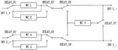
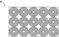
도 4는, 가열 유닛의 일 예로서 10개의 가열 코일들을 구비하는 경우를 도시한다. 도 5를 참조하면, 도 4의 가열 코일들 중 5개의 가열 코일들과 두 개의 인버터들이 서로 연결되는 결선도로서, 중간에 복수 개의 릴레이들이 구비된다.Fig. 4 shows a case in which ten heating coils are provided as an example of the heating unit. Referring to FIG. 5, five heating coils and two inverters among the heating coils of FIG. 4 are connected to each other, and a plurality of relays are provided in the middle.
도 4에 도시한 가열 코일들은 도 8에 도시한 바와 같이 각각 납작한 리츠 선(Flat Litz Wire) 방식으로 만들어질 수 있다. 납작한 리츠 선 방식의 코일들은 원형 리츠 선 방식의 가열 코일들을 압착하여 형성되는 것이 좋다. 납작한 리츠 선 방식의 가열 코일은 일정 폭에 많은 턴 수의 코일을 감을 수 있다.The heating coils shown in FIG. 4 may be formed by a flat Litz wire method, as shown in FIG. The flat Ritz line type coils are preferably formed by squeezing the circular Ritz line heating coils. A flat Ritz line heating coil can wind a large number of turns of coil at a certain width.
도 5 및 도 6을 참조하면, 제1 인버터(INV 1)와 제2 인버터(INV 2)가 릴레이들(RELAY_01 내지 RELAY_07)을 거쳐 가열 코일들(WC1 내지 WC5)에 고주파 전압을 인가한다.5 and 6, the
용기가 가열 코일 1(WC 1)이 담당하는 가열 영역에 놓인 경우를 설명한다. 가열 코일 1(WC 1)은 인버터 1(INV 1)으로부터 전력을 공급받고, 릴레이 1, 릴레이 3, 릴레이 5에 의해 연결된다. 즉, 가열 코일 1이 동작하기 위해서는, 제어 유닛은 각각 릴레이 1에 '0', 릴레이 3에 '0', 릴레이 5에 '0'의 개폐 신호를 출력한다.A case where the container is placed in the heating area occupied by the heating coil 1 (WC 1) will be described. The heating coil 1 (WC 1) receives electric power from the inverter 1 (INV 1) and is connected by the
마찬가지로, 가열 코일 2(WC 2)의 경우에, 제어 유닛은 릴레이 1에 '1', 릴레이 3에 '1', 릴레이 5에 '0'의 개폐 신호를 출력한다.Similarly, in the case of the heating coil 2 (WC 2), the control unit outputs '1' to the
한편, 가열 코일 3(WC 3)은 릴레이 1, 릴레이 3, 릴레이 5, 및 릴레이 7에 의해서 인버터 1과 연결된다. 가열 코일 3이 가열되기 위해서는, 제어 유닛은 릴레이 1에 '1', 릴레이 3에 '0', 릴레이 5에 '1', 릴레이 7에 '0'의 개폐 신호를 각각 출력한다.On the other hand, the heating coil 3 (WC 3) is connected to the
가열 코일 4(WC 4)와 가열 코일(WC 5)은 인버터 2(INV 2)로부터 전력을 공급받는다. 가열 코일 4 및 가열 코일 5의 동작은 도 5 및 도 6을 참조한다.The heating coil 4 (WC 4) and the heating coil (WC 5) are supplied with power from the inverter 2 (INV 2). The operation of the
만약 용기가 가열 코일 1 및 가열 코일 2에 걸쳐 놓여 있다면, 제어 유닛은 릴레이 1에 '0', 릴레이 3에 '1', 릴레이 5에 '0'의 개폐 신호를 출력하여 인버터 1(INV 1)이 가열 코일 1 및 가열 코일 2에 전력을 공급하도록 한다. 이때, 가열 코일 1과 가열 코일 2는 서로 직렬 연결된다. 즉, 하나의 인버터에 대하여 두 개의 가열 코일들이 서로 병렬이 아닌 직렬로 연결되어 가열 코일들에 흐르는 전류가 낮아진다. 따라서, 인버터 내의 스위칭 소자들, 예를 들어 IGBT, MOSFET 등의 전류 정격을 낮출 수 있다.If the container is placed over the
만약 용기가 가열 코일 3 내지 5에 걸쳐 놓여 있다면, 제어 유닛은 릴레이 2(RELAY 2)에 '0', 릴레이 4 내지 7(RELAY 4 내지 7)에 '1'의 개폐 신호를 출력하여 인버터 2(INV 2)가 가열 코일 3 내지 5에 전력을 공급하도록 한다. 이 경우에도 가열 코일 3 내지 5는 서로 직렬 연결된다.If the container is laid over the heating coils 3 to 5, the control unit outputs '0' to the relay 2 (RELAY 2) and '1' to the
도 7은 가열 코일들 및 릴레이들의 결선의 다른 예를 보인다. 즉, 같은 수의 인버터, 가열 코일들, 릴레이들을 가지나, 도 7의 유도 가열 조리 장치는 도 5의 유도 가열 조리 장치와 다른 결선을 가질 수 있다. 이 경우에도 마찬가지로, 제어 유닛이 용기가 놓인 가열 영역에 해당하는 가열 코일들을 연결하는 릴레이들에 개폐 신호를 출력하여 가열 코일을 가열할 수 있다. 물론 경우의 수는 도 6과 다를 수 있다.7 shows another example of the connection of heating coils and relays. That is, the same number of inverters, heating coils, and relays are provided, but the induction heating cooking apparatus of FIG. 7 may have a different connection from the induction heating cooking apparatus of FIG. In this case as well, the control unit can heat the heating coil by outputting an opening / closing signal to the relays connecting the heating coils corresponding to the heating region in which the container is placed. Of course, the number of cases may be different from FIG.
도 9를 참조하면, 일 실시 예에 따른 유도 가열 조리 장치의 제어 방법은, 용기가 놓인 하나 이상의 가열 영역을 검출하는 단계(S100)와, 상기 복수의 릴레이들에 의해 상기 가열 영역에 해당하는 하나 이상의 상기 가열 코일과, 상기 인버터들 중 하나 이상의 상기 인버터의 사이를 연결하는 단계(S200)와, 제어 명령을 입력받는 단계(S300)와, 상기 제어 명령에 따라 해당 인버터를 구동하는 단계(S400)를 포함하여 구성된다. 이하 장치의 구성은 도 2 내지 도 8을 함께 참조한다.Referring to FIG. 9, a method of controlling an induction heating cooking apparatus according to an embodiment includes detecting (S100) at least one heating zone on which a container is placed, A step S200 of connecting the heating coil and at least one inverter among the inverters, a step S300 of receiving a control command, and a step S400 of driving the inverter in accordance with the control command. . The construction of the apparatus will be described below with reference to Figs.
상기 가열 영역을 검출하는 단계(S100)는, 상기 가열 코일들의 전류를 감지하여 전류 값을 출력하는 과정과, 상기 전류 값과 일정 기준 전류 값을 비교하는 과정을 포함할 수 있고, 비교 결과를 근거로 상기 용기가 놓인 상기 하나 이상의 가열 영역을 검출한다. 물론 다른 형태의 감지 값을 이용하여 용기가 놓인 가열 영역을 검출할 수 있다.The step of detecting the heating region (S100) may include a step of sensing a current of the heating coils and outputting a current value, and a step of comparing the current value with a predetermined reference current value. To detect the at least one heating zone on which the vessel is placed. Of course, other types of sensing values can be used to detect the heating zone on which the vessel is placed.
도 4 내지 도 7을 참조하여 본 발명의 실시 예들에 따른 유도 가열 조리 장치의 제어 방법을 간단히 설명한다.4 to 7, a control method of the induction heating cooking apparatus according to the embodiments of the present invention will be briefly described.
도 4는, 가열 유닛의 일 예로서 10개의 가열 코일들을 구비하는 경우를 도시한다. 도 5를 참조하면, 도 4의 가열 코일들 중 5개의 가열 코일들과 두 개의 인버터들이 서로 연결되는 결선도로서, 중간에 복수 개의 릴레이들이 구비된다.Fig. 4 shows a case in which ten heating coils are provided as an example of the heating unit. Referring to FIG. 5, five heating coils and two inverters among the heating coils of FIG. 4 are connected to each other, and a plurality of relays are provided in the middle.
도 5 및 도 6을 참조하면, 제1 인버터(INV 1)와 제2 인버터(INV 2)가 릴레이들(RELAY_01 내지 RELAY_07)을 거쳐 가열 코일들(WC1 내지 WC5)에 고주파 전압을 인가한다.5 and 6, the
용기가 가열 코일 1(WC 1)이 담당하는 가열 영역에 놓인 경우를 설명한다. 즉, 용기가 가열 코일 1에 놓이면, 가열 코일 1의 전류 값이 변하게 되고, 기준 전류 값 이상이 되면 용기가 가열 코일 1이 담당하는 가열 영역에 놓인 것으로 판단한다(S100). 가열 코일 1(WC 1)은 인버터 1(INV 1)으로부터 전력을 공급받고, 릴레이 1, 릴레이 3, 릴레이 5에 의해 연결된다. 즉, 가열 코일 1은 릴레이 1 및 릴레이 3에 의해 인버터 1에 연결된다(S200). 이때, 제어 유닛은 릴레이 1에 '0', 릴레이 3에 '0', 릴레이 5에 '0'의 개폐 신호를 출력한다. 그런 다음 유도 가열 조리 장치는 사용자로부터 용기에 대한 제어 명령을 입력받고(S300), 제어 명령에 따른 제어 신호를 생성하여 인버터 1에 구동한다(S400).A case where the container is placed in the heating area occupied by the heating coil 1 (WC 1) will be described. That is, when the container is placed on the
마찬가지로, 가열 코일 2(WC 2)의 경우에, 제어 유닛은 릴레이 1에 '1', 릴레이 3에 '1', 릴레이 5에 '0'의 개폐 신호를 출력한다. 즉, 가열 코일 2에 용기가 놓인 것으로 검출하면(S100), 유도 가열 조리 장치는 가열 코일 2를 릴레이 1, 릴레이 3, 릴레이 5에 의해 인버터 1에 연결하고, 가열 코일 2에 전력을 공급한다(S200).Similarly, in the case of the heating coil 2 (WC 2), the control unit outputs '1' to the
한편, 가열 코일 3(WC 3)은 릴레이 1, 릴레이 3, 릴레이 5, 및 릴레이 7에 의해서 인버터 1과 연결된다. 가열 코일 3이 가열되기 위해서는, 제어 유닛은 릴레이 1에 '1', 릴레이 3에 '0', 릴레이 5에 '1', 릴레이 7에 '0'의 개폐 신호를 각각 출력한다.On the other hand, the heating coil 3 (WC 3) is connected to the
가열 코일 4(WC 4)와 가열 코일(WC 5)은 인버터 2(INV 2)로부터 전력을 공급받는다. 가열 코일 4 및 가열 코일 5의 동작은 도 5 및 도 6을 참조한다.The heating coil 4 (WC 4) and the heating coil (WC 5) are supplied with power from the inverter 2 (INV 2). The operation of the
만약 용기가 가열 코일 3 및 가열 코일 5에 걸쳐 놓여 있다고 검출되면(S100), 유도 가열 조리 장치는 가열 코일 3 및 가열 코일 5를 릴레이들을 통해 인버터 2에 연결한다(S200). 이때, 제어 유닛은 해당 릴레이들, 즉 릴레이 2에 '1', 릴레이 4에 '1', 릴레이 6에 '1', 릴레이 7에 '1'의 개폐 신호를 출력하여 가열 코일 3 및 가열 코일 5가 인버터 2에 연결되도록 한다. 이때, 가열 코일 3과 가열 코일 5는 서로 직렬 연결된다. 즉, 하나의 인버터에 대하여 두 개의 가열 코일들이 서로 병렬이 아닌 직렬로 연결되어 가열 코일들에 흐르는 전류가 낮아진다. 따라서, 인버터 내의 스위칭 소자들, 예를 들어 IGBT, MOSFET 등의 전류 정격을 낮출 수 있다. 그런 다음, 유도 가열 조리 장치는 사용자의 제어 명령에 따라 가열 코일 3 및 가열 코일 5에 대한 인버터 2를 구동한다(S300, S400).If it is detected that the container is laid over the
만약 용기가 가열 코일 3 내지 5에 걸쳐 놓여 있다고 검출되면(S100), 제어 유닛은 릴레이 2(RELAY 2)에 '0', 릴레이 4 내지 7(RELAY 4 내지 7)에 '1'의 개폐 신호를 출력하여 인버터 2(INV 2)가 가열 코일 3 내지 5에 전력을 공급하도록 한다(S200). 이 경우에도 가열 코일 3 내지 5는 서로 직렬 연결된다.If it is detected that the container is laid over the heating coils 3 to 5 (S100), the control unit outputs '0' to the relay 2 (RELAY 2) and '1' to the
도 7은 가열 코일들 및 릴레이들의 결선의 다른 예를 보인다. 즉, 같은 수의 인버터, 가열 코일들, 릴레이들을 가지나, 도 7의 유도 가열 조리 장치는 도 5의 유도 가열 조리 장치와 다른 결선을 가질 수 있다. 이 경우에도 마찬가지로, 제어 유닛이 용기가 놓인 가열 영역에 해당하는 가열 코일들을 연결하는 릴레이들에 개폐 신호를 출력하여 가열 코일을 가열할 수 있다. 물론 가열 영역에 따른 릴레이 및 가열 코일의 결선 방식은 도 6과 다를 수 있다.7 shows another example of the connection of heating coils and relays. That is, the same number of inverters, heating coils, and relays are provided, but the induction heating cooking apparatus of FIG. 7 may have a different connection from the induction heating cooking apparatus of FIG. In this case as well, the control unit can heat the heating coil by outputting an opening / closing signal to the relays connecting the heating coils corresponding to the heating region in which the container is placed. Of course, the connection method of the relay and the heating coil according to the heating region may be different from that of FIG.
이상 설명한 바와 같이, 본 발명의 실시 예들에 따른 유도 가열 조리 장치 및 이의 제어 방법은 복수의 가열 코일들을 이용하여 용기의 위치에 관계없이 용기를 효율적으로 가열할 수 있다. 본 발명의 실시 예들은 복수의 가열 코일들을 릴레이를 통해 소수의 인버터와 연결함으로써 복수의 가열 코일들 중 용기가 놓인 위치에 대해서만 가열할 수 있도록 하고, 가열 코일들을 직렬로 연결함으로써 가열 코일에 흐르는 전류를 낮춤으로써 인버터의 전류 정격을 낮출 수 있다. 본 발명의 실시 예들은 인버터의 개수를 최소로 줄이면서 많은 수의 가열 코일을 동작시킬 수 있도록 릴레이 및 가열 코일을 결선함으로써 제조 비용을 줄이고 동작 효율을 증대시킴과 동시에 조리 장치의 안정성을 제고한다.INDUSTRIAL APPLICABILITY As described above, the induction heating cooking apparatus and the control method thereof according to the embodiments of the present invention can efficiently heat the vessel regardless of the position of the vessel using a plurality of heating coils. Embodiments of the present invention allow a plurality of heating coils to be connected to a small number of inverters through a relay so that only one of a plurality of heating coils can be heated only at a position where the container is placed, and by connecting the heating coils in series, The current rating of the inverter can be lowered. Embodiments of the present invention reduce the manufacturing cost, increase the operation efficiency, and improve the stability of the cooking apparatus by connecting the relay and the heating coil so that a large number of heating coils can be operated while reducing the number of inverters to a minimum.
100, 110~140: 가열 유닛200, 210~240: 인버터
300, 310~340: 릴레이400: 제어 유닛
500, 510~5400: 감지 유닛600, 610, 620: 구동 유닛
700, 710, 720: 컨버터800, 810, 820: 평활 유닛100, 110 to 140:
300, 310 to 340: Relay 400: Control unit
500, 510 to 5400: sensing
700, 710, 720:
Claims (16)
Translated fromKorean상기 가열 코일들 중 하나 이상의 가열 코일에 구동 전압을 공급하는 복수의 인버터들;
상기 용기가 놓인 하나 이상의 가열 영역을 검출하고, 제어 명령에 따라 상기 복수의 인버터들을 제어하는 제어 유닛;
각각에 대한 개폐 신호들을 근거로, 상기 제어 유닛이 검출한 가열 영역에 해당하는 하나 이상의 상기 가열 코일과, 상기 인버터들 중 하나 이상의 상기 인버터의 사이를 연결하는 복수의 릴레이들; 및
상기 가열 코일들의 전류를 감지하고 전류 값을 출력하는 감지 유닛;을 더 포함하고,
상기 제어 유닛은,
상기 전류 값과 일정 기준 전류 값을 비교하고 비교 결과를 근거로 상기 용기가 놓인 상기 하나 이상의 가열 영역을 검출하고,
검출된 가열 영역에 대응되는 가열 코일들 중 동일한 인버터에 연결 가능한 가열 코일들이 상기 릴레이들 중 일부에 의해 서로 직렬 연결되도록 상기 릴레이들의 구동을 제어하는 것을 특징으로 하는 유도 가열 조리 장치.A heating unit including a plurality of heating coils each for forming a heating region and for heating a container placed in the heating region;
A plurality of inverters for supplying a driving voltage to at least one of the heating coils;
A control unit for detecting at least one heating zone on which said vessel is placed, and for controlling said plurality of inverters in accordance with a control command;
A plurality of relays connecting between the at least one heating coil corresponding to the heating region detected by the control unit and one or more of the inverters based on the opening and closing signals for each of the plurality of relays; And
And a sensing unit for sensing a current of the heating coils and outputting a current value,
Wherein the control unit comprises:
Comparing the current value with a predetermined reference current value, detecting the one or more heating regions on which the container is placed based on the comparison result,
And controls the driving of the relays so that the heating coils connectable to the same inverter among the heating coils corresponding to the detected heating region are connected in series to each other by a part of the relays.
상기 인버터의 수는 상기 가열 코일의 수보다 적은 것을 특징으로 하는 유도 가열 조리 장치.The method according to claim 1,
Wherein the number of the inverters is smaller than the number of the heating coils.
상기 복수의 인버터들 각각은,
상기 복수의 가열 코일들 중 일부에 상기 구동 전압을 공급하도록 연결되는 것을 특징으로 하는 유도 가열 조리 장치.3. The method of claim 2,
Wherein each of the plurality of inverters comprises:
Wherein the heating coil is connected to supply the driving voltage to a part of the plurality of heating coils.
하프 브리지 방식, 풀 브리지 방식, 및 Class E 방식 중 하나의 방식으로 이루어지는 것을 특징으로 하는 유도 가열 조리 장치.2. The inverter of claim 1,
A half bridge method, a full bridge method, and a Class E method.
납작한 리츠 선(Flat Litz Wire) 방식인 것을 특징으로 하는 유도 가열 조리 장치.The heating coil according to any one of claims 1 to 3,
Characterized in that it is a flat Litz wire system.
납작한 리츠 선 방식의 코일들은 원형 리츠 선 방식의 가열 코일들을 압착하여 형성되는 것을 특징으로 하는 유도 가열 조리 장치.8. The method of claim 7,
Wherein the flattened Litz wire type coils are formed by squeezing the heating coils of the circular Litz wire type.
상기 가열 코일들에 연결되어 공진을 발생하는 공진 커패시터들;을 더 포함하는 유도 가열 조리 장치.9. The heating apparatus according to claim 8,
And resonance capacitors connected to the heating coils to generate resonance.
상기 컨버터의 출력 직류 전압을 평활화하는 평활 유닛;
각각 가열 영역을 형성하고 상기 가열 영역에 놓인 용기를 가열하는 복수의 가열 코일들, 및 상기 가열 코일들에 연결되어 공진을 발생하는 공진 커패시터들을 포함하는 가열 유닛;
제어 신호에 따라 상기 평활 유닛이 평활화한 직류 전압을 구동 전압으로 변환하고, 상기 가열 코일들 중 하나 이상의 가열 코일에 상기 구동 전압을 공급하는 복수의 인버터들;
상기 가열 유닛에 대한 제어 명령을 입력받는 입력 유닛;
상기 용기가 놓인 하나 이상의 가열 영역을 검출하고, 상기 제어 명령에 따라 상기 복수의 인버터들을 제어하는 상기 제어 신호를 발생하는 제어 유닛;
각각에 대한 개폐 신호들을 근거로, 상기 제어 유닛이 검출한 가열 영역에 해당하는 하나 이상의 상기 가열 코일과, 상기 인버터들 중 하나 이상의 상기 인버터의 사이를 연결하는 복수의 릴레이들; 및
상기 가열 코일들의 전류를 감지하고 전류 값을 출력하는 감지 유닛;을 더 포함하고,
상기 제어 유닛은,
상기 전류 값과 일정 기준 전류 값을 비교하고 비교 결과를 근거로 상기 용기가 놓인 상기 하나 이상의 가열 영역을 검출하고,
검출된 가열 영역에 대응되는 가열 코일들 중 동일한 인버터에 연결 가능한 가열 코일들이 상기 릴레이들 중 일부에 의해 서로 직렬 연결되도록 상기 릴레이들의 구동을 제어하는 것을 특징으로 하는 유도 가열 조리 장치.A converter for converting an input voltage of a commercial AC power source into a DC voltage and outputting the DC voltage;
A smoothing unit for smoothing the output DC voltage of the converter;
A heating unit including a plurality of heating coils each for forming a heating region and heating a container placed in the heating region, and resonance capacitors connected to the heating coils for generating resonance;
A plurality of inverters for converting a DC voltage smoothed by the smoothing unit into a driving voltage in accordance with a control signal and supplying the driving voltage to at least one heating coil of the heating coils;
An input unit for receiving a control command for the heating unit;
A control unit for detecting at least one heating zone on which said vessel is placed and generating said control signal for controlling said plurality of inverters in accordance with said control command;
A plurality of relays connecting between the at least one heating coil corresponding to the heating region detected by the control unit and one or more of the inverters based on the opening and closing signals for each of the plurality of relays; And
And a sensing unit for sensing a current of the heating coils and outputting a current value,
Wherein the control unit comprises:
Comparing the current value with a predetermined reference current value, detecting the one or more heating regions on which the container is placed based on the comparison result,
And controls the driving of the relays so that the heating coils connectable to the same inverter among the heating coils corresponding to the detected heating region are connected in series to each other by a part of the relays.
제1 인버터에 의해 구동되고, 서로 직렬 연결되며 제1 가열 영역을 형성하는 둘 이상의 가열 코일들로 형성되는 제1 코일부;
제2 인버터에 의해 구동되고, 서로 직렬 연결되며 제2 가열 영역을 형성하는 둘 이상의 가열 코일들로 형성되는 제2 코일부; 및
상기 제1 인버터 또는 상기 제2 인버터에 의해 구동되고, 상기 제1 코일부 또는 상기 제2 코일부에 직렬 연결되거나, 또는 상기 제1 인버터 또는 상기 제2 인버터에 직접 연결되어 제3 가열 영역을 형성하는 하나 이상의 가열 코일들로 형성되는 제3 코일부;를 포함하는 것을 특징으로 하는 유도 가열 조리 장치.11. The apparatus according to claim 10,
A first coil part driven by a first inverter and connected to each other in series and formed of two or more heating coils forming a first heating area;
A second coil part driven by a second inverter and connected to each other in series and formed of two or more heating coils forming a second heating area; And
And a third heating region driven by the first inverter or the second inverter and connected in series to the first coil portion or the second coil portion or directly connected to the first inverter or the second inverter And a third coil part formed of one or more heating coils for making the induction heating cooker.
납작한 리츠 선(Flat Litz Wire) 방식인 것을 특징으로 하는 유도 가열 조리 장치.13. The heating coil according to claim 10 or 12,
Characterized in that it is a flat Litz wire system.
납작한 리츠 선 방식의 코일들은 원형 리츠 선 방식의 가열 코일들을 압착하여 형성되는 것을 특징으로 하는 유도 가열 조리 장치.14. The method of claim 13,
Wherein the flattened Litz wire type coils are formed by squeezing the heating coils of the circular Litz wire type.
상기 용기가 놓인 하나 이상의 가열 영역을 검출하는 단계;
상기 복수의 릴레이들에 의해 상기 가열 영역에 해당하는 하나 이상의 상기 가열 코일과, 상기 인버터들 중 하나 이상의 상기 인버터의 사이를 연결하는 단계;
제어 명령을 입력받는 단계; 및
상기 제어 명령에 따라 해당 인버터를 구동하는 단계;를 포함하고,
상기 가열 영역에 해당하는 하나 이상의 상기 가열 코일 중 동일한 인버터에 연결 가능한 코일들은 상기 릴레이에 의해 서로 직렬연결되는 것을 특징으로 하는 유도 가열 조리 장치의 제어 방법.A heating unit including a plurality of heating coils for respectively forming a heating region and heating the container placed in the heating region; a plurality of inverters for supplying a driving voltage to at least one heating coil of the heating coils; And a heating unit for heating the cooking cavity,
Detecting at least one heating zone over which the vessel is placed;
Connecting at least one heating coil corresponding to the heating zone by the plurality of relays and at least one inverter of the inverters;
Receiving a control command; And
And driving the inverter according to the control command,
Wherein the coils connectable to the same inverter among the at least one heating coil corresponding to the heating region are connected to each other in series by the relay.
상기 가열 코일들의 전류를 감지하여 전류 값을 출력하는 과정; 및
상기 전류 값과 일정 기준 전류 값을 비교하는 과정;을 포함하고,
비교 결과를 근거로 상기 용기가 놓인 상기 하나 이상의 가열 영역을 검출하는 것을 특징으로 하는 유도 가열 조리 장치의 제어 방법.16. The method of claim 15, wherein detecting the heating region comprises:
Detecting a current of the heating coils and outputting a current value; And
And comparing the current value with a predetermined reference current value,
And detects the at least one heating region on which the container is placed based on the comparison result.
Priority Applications (3)
| Application Number | Priority Date | Filing Date | Title |
|---|---|---|---|
| KR1020120028914AKR101970524B1 (en) | 2012-03-21 | 2012-03-21 | Induction heating cooker and controlling method thereof |
| US13/837,717US9271337B2 (en) | 2012-03-21 | 2013-03-15 | Induction heating cooking apparatus and control method thereof |
| EP13159724.7AEP2642819B1 (en) | 2012-03-21 | 2013-03-18 | Induction heating cooking apparatus and control method thereof |
Applications Claiming Priority (1)
| Application Number | Priority Date | Filing Date | Title |
|---|---|---|---|
| KR1020120028914AKR101970524B1 (en) | 2012-03-21 | 2012-03-21 | Induction heating cooker and controlling method thereof |
Publications (2)
| Publication Number | Publication Date |
|---|---|
| KR20130107090A KR20130107090A (en) | 2013-10-01 |
| KR101970524B1true KR101970524B1 (en) | 2019-04-19 |
Family
ID=47900903
Family Applications (1)
| Application Number | Title | Priority Date | Filing Date |
|---|---|---|---|
| KR1020120028914AActiveKR101970524B1 (en) | 2012-03-21 | 2012-03-21 | Induction heating cooker and controlling method thereof |
Country Status (3)
| Country | Link |
|---|---|
| US (1) | US9271337B2 (en) |
| EP (1) | EP2642819B1 (en) |
| KR (1) | KR101970524B1 (en) |
Families Citing this family (20)
| Publication number | Priority date | Publication date | Assignee | Title |
|---|---|---|---|---|
| ES2782899T3 (en)* | 2013-08-02 | 2020-09-16 | Bsh Hausgeraete Gmbh | Cooking field device |
| KR101515026B1 (en)* | 2014-03-05 | 2015-04-24 | 주식회사 리홈쿠첸 | Induction heater having multiple working coil |
| KR101488731B1 (en)* | 2014-03-05 | 2015-02-03 | 주식회사 리홈쿠첸 | Induction heater having multiple working coil |
| TWI661782B (en)* | 2014-05-21 | 2019-06-11 | 瑞士商菲利浦莫里斯製品股份有限公司 | Electrically heated aerosol-generating system,electrically heated aerosol-generating deviceand method of generating an aerosol |
| US10278238B2 (en) | 2014-11-07 | 2019-04-30 | Breville Pty Limited | Cooktop |
| KR101706964B1 (en)* | 2015-05-12 | 2017-02-15 | 엘지전자 주식회사 | Cooking appliance and Methof for controlling it |
| US20170164777A1 (en)* | 2015-12-10 | 2017-06-15 | Spectrum Brands, Inc. | Induction cooktop |
| CN106196199B (en)* | 2016-07-14 | 2018-11-13 | 广东美的厨房电器制造有限公司 | Whole district's electromagnetic stove and its method for heating and controlling and heating control apparatus |
| DE102016216041A1 (en)* | 2016-08-25 | 2018-03-01 | Robert Bosch Gmbh | Method and control device for heating a device driven by a brushless DC motor |
| JP6920595B2 (en)* | 2016-08-30 | 2021-08-18 | パナソニックIpマネジメント株式会社 | Induction heating cooker |
| KR102713158B1 (en)* | 2016-12-08 | 2024-10-07 | 삼성전자주식회사 | Cooking apparatus |
| US11000157B2 (en)* | 2017-05-19 | 2021-05-11 | Hatco Corporation | Hot and cold holding system |
| US11064575B2 (en) | 2017-10-19 | 2021-07-13 | Lg Electronics Inc. | Induction heating device having improved target object detection accuracy and induction heating system including the same |
| US10993292B2 (en)* | 2017-10-23 | 2021-04-27 | Whirlpool Corporation | System and method for tuning an induction circuit |
| KR102071957B1 (en) | 2018-04-19 | 2020-01-31 | 엘지전자 주식회사 | Induction heating device having improved control algorithm and circuit structure |
| KR102082507B1 (en)* | 2018-05-16 | 2020-02-27 | 엘지전자 주식회사 | Induction heating device having improved control algorithm and circuit structure |
| KR102175638B1 (en)* | 2019-03-28 | 2020-11-06 | (주)쿠첸 | Heating device including a plurality of sub working coils |
| KR20210078266A (en)* | 2019-12-18 | 2021-06-28 | 엘지전자 주식회사 | Wireless induction heating cooker that improves cooking uniformity |
| EP4209117A1 (en)* | 2020-09-02 | 2023-07-12 | BSH Hausgeräte GmbH | Cooktop device and method for operating a cooktop device |
| GB202212636D0 (en)* | 2022-08-31 | 2022-10-12 | Nicoventures Trading Ltd | Electronic circuit for an aerosol generator of an aerosol provision device |
Citations (3)
| Publication number | Priority date | Publication date | Assignee | Title |
|---|---|---|---|---|
| JP2009238575A (en)* | 2008-03-27 | 2009-10-15 | Mitsubishi Electric Corp | Induction heating cooking appliance |
| WO2010069883A1 (en)* | 2008-12-19 | 2010-06-24 | BSH Bosch und Siemens Hausgeräte GmbH | Induction hob and method for operating an induction hob |
| JP2010251093A (en)* | 2009-04-15 | 2010-11-04 | Panasonic Corp | Induction heating device |
Family Cites Families (11)
| Publication number | Priority date | Publication date | Assignee | Title |
|---|---|---|---|---|
| US3953783A (en) | 1971-04-06 | 1976-04-27 | Environment/One Corporation | Low cast chopper inverter power supply and gating circuit therefor |
| US4013859A (en)* | 1975-06-04 | 1977-03-22 | Environment/One Corporation | Induction cooking unit having cooking load sensing device and essentially zero stand-by power loss |
| JPH0612699B2 (en)* | 1985-11-27 | 1994-02-16 | 株式会社東芝 | Induction heating cooker |
| KR100241449B1 (en)* | 1997-08-22 | 2000-03-02 | 구자홍 | Apparatus and method for judging small load of induction heating cooker |
| US6528770B1 (en) | 1999-04-09 | 2003-03-04 | Jaeger Regulation | Induction cooking hob with induction heaters having power supplied by generators |
| US7009159B2 (en)* | 2002-03-19 | 2006-03-07 | Matsushita Electric Industrial Co., Ltd. | Induction heating apparatus having electrostatic shielding member |
| FR2839604A1 (en) | 2002-05-07 | 2003-11-14 | Jaeger Controls | Induction module for electric cooking, comprises two inductors each having two independent windings associated with switches which may connect them directly or in series to the rectified supply |
| US7589301B2 (en) | 2006-04-14 | 2009-09-15 | Ixys Corporation | Induction heating device having plural resonant circuits |
| ES2352772B1 (en) | 2008-12-19 | 2012-01-26 | Bsh Electrodomésticos España, S.A. | COOKING FIELD WITH VARIOUS HEATING ELEMENTS AND AT LEAST A CONSTRUCTION GROUP OF POWER ELECTRONICS. |
| ES2353890B1 (en)* | 2008-12-19 | 2012-01-26 | Bsh Electrodomesticos España, S.A. | COOKING FIELD WITH AT LEAST THREE WARMING AREAS. |
| ES2388028B1 (en) | 2010-03-03 | 2013-08-23 | Bsh Electrodomésticos España, S.A. | COOKING HOB WITH AT LEAST ONE COOKING AREA AND PROCEDURE TO OPERATE A COOKING HOB. |
- 2012
- 2012-03-21KRKR1020120028914Apatent/KR101970524B1/enactiveActive
- 2013
- 2013-03-15USUS13/837,717patent/US9271337B2/enactiveActive
- 2013-03-18EPEP13159724.7Apatent/EP2642819B1/enactiveActive
Patent Citations (3)
| Publication number | Priority date | Publication date | Assignee | Title |
|---|---|---|---|---|
| JP2009238575A (en)* | 2008-03-27 | 2009-10-15 | Mitsubishi Electric Corp | Induction heating cooking appliance |
| WO2010069883A1 (en)* | 2008-12-19 | 2010-06-24 | BSH Bosch und Siemens Hausgeräte GmbH | Induction hob and method for operating an induction hob |
| JP2010251093A (en)* | 2009-04-15 | 2010-11-04 | Panasonic Corp | Induction heating device |
Also Published As
| Publication number | Publication date |
|---|---|
| US20130248517A1 (en) | 2013-09-26 |
| US9271337B2 (en) | 2016-02-23 |
| EP2642819A2 (en) | 2013-09-25 |
| EP2642819A3 (en) | 2014-06-04 |
| KR20130107090A (en) | 2013-10-01 |
| EP2642819B1 (en) | 2015-08-12 |
Similar Documents
| Publication | Publication Date | Title |
|---|---|---|
| KR101970524B1 (en) | Induction heating cooker and controlling method thereof | |
| CN102484907B (en) | Induction heating apparatus | |
| EP2753146B1 (en) | Induction heat cooking apparatus and method for controlling output level thereof | |
| KR101659001B1 (en) | Indution Heating Cooktop with a single inverter and Control Method thereof | |
| EP2753147B1 (en) | Induction heat cooking apparatus | |
| KR101743495B1 (en) | Cooking apparatus using induction heeating | |
| CN102144885A (en) | Induction heating cooker | |
| US20110253706A1 (en) | Heating device with plural induction coils | |
| CN107023861B (en) | Induction heating cooking apparatus | |
| KR20190040843A (en) | Induction heating apparatus | |
| JP2011044422A (en) | Induction heating cooker | |
| EP2753145B1 (en) | Induction heat cooking apparatus | |
| KR20150084617A (en) | Induction heating apparatus | |
| JP2003257604A (en) | Inverter cooker | |
| Pérez-Tarragona et al. | Full-bridge series resonant multi-inverter featuring new 900-V SiC devices for improved induction heating appliances | |
| KR101604748B1 (en) | Indution Heating Cooktop with a single inverter and Control Method thereof | |
| CN103548416B (en) | Induction heating apparatus and operation method thereof and the home appliances of band induction heating apparatus | |
| KR101611277B1 (en) | Cooking apparatus using induction heeating | |
| KR20090005142U (en) | Induction Heater | |
| US20220256660A1 (en) | Induction heating apparatus and method for controlling induction heating apparatus | |
| KR101659000B1 (en) | Indution Heating Cooktop with a single inverter and Control Method thereof | |
| Rehm et al. | A modular, non-resonant multi-output inverter for use in flexible cooking surfaces | |
| KR102182624B1 (en) | Induction heat cooking apparatus and method for driving the same | |
| Rubavathy et al. | Pulse Density Modulation Based Series Resonant Inverter Fed Induction Heater System | |
| JP3193142U (en) | Induction heating control circuit for commercial rice cookers |
Legal Events
| Date | Code | Title | Description |
|---|---|---|---|
| PA0109 | Patent application | Patent event code:PA01091R01D Comment text:Patent Application Patent event date:20120321 | |
| PG1501 | Laying open of application | ||
| A201 | Request for examination | ||
| PA0201 | Request for examination | Patent event code:PA02012R01D Patent event date:20170119 Comment text:Request for Examination of Application Patent event code:PA02011R01I Patent event date:20120321 Comment text:Patent Application | |
| E902 | Notification of reason for refusal | ||
| PE0902 | Notice of grounds for rejection | Comment text:Notification of reason for refusal Patent event date:20171213 Patent event code:PE09021S01D | |
| E90F | Notification of reason for final refusal | ||
| PE0902 | Notice of grounds for rejection | Comment text:Final Notice of Reason for Refusal Patent event date:20180814 Patent event code:PE09021S02D | |
| E701 | Decision to grant or registration of patent right | ||
| PE0701 | Decision of registration | Patent event code:PE07011S01D Comment text:Decision to Grant Registration Patent event date:20190125 | |
| GRNT | Written decision to grant | ||
| PR0701 | Registration of establishment | Comment text:Registration of Establishment Patent event date:20190415 Patent event code:PR07011E01D | |
| PR1002 | Payment of registration fee | Payment date:20190416 End annual number:3 Start annual number:1 | |
| PG1601 | Publication of registration | ||
| PR1001 | Payment of annual fee | Payment date:20220308 Start annual number:4 End annual number:4 | |
| PR1001 | Payment of annual fee | Payment date:20240308 Start annual number:6 End annual number:6 | |
| PR1001 | Payment of annual fee | Payment date:20250324 Start annual number:7 End annual number:7 |