KR101967324B1 - Divot detectable golf swing mat - Google Patents
Divot detectable golf swing matDownload PDFInfo
- Publication number
- KR101967324B1 KR101967324B1KR1020170121966AKR20170121966AKR101967324B1KR 101967324 B1KR101967324 B1KR 101967324B1KR 1020170121966 AKR1020170121966 AKR 1020170121966AKR 20170121966 AKR20170121966 AKR 20170121966AKR 101967324 B1KR101967324 B1KR 101967324B1
- Authority
- KR
- South Korea
- Prior art keywords
- unit
- club head
- golf ball
- mat
- light emitting
- Prior art date
- Legal status (The legal status is an assumption and is not a legal conclusion. Google has not performed a legal analysis and makes no representation as to the accuracy of the status listed.)
- Active
Links
Images


Classifications
- A—HUMAN NECESSITIES
- A63—SPORTS; GAMES; AMUSEMENTS
- A63B—APPARATUS FOR PHYSICAL TRAINING, GYMNASTICS, SWIMMING, CLIMBING, OR FENCING; BALL GAMES; TRAINING EQUIPMENT
- A63B69/00—Training appliances or apparatus for special sports
- A63B69/36—Training appliances or apparatus for special sports for golf
- A63B69/3614—Training appliances or apparatus for special sports for golf using electro-magnetic, magnetic or ultrasonic radiation emitted, reflected or interrupted by the golf club
- A—HUMAN NECESSITIES
- A63—SPORTS; GAMES; AMUSEMENTS
- A63B—APPARATUS FOR PHYSICAL TRAINING, GYMNASTICS, SWIMMING, CLIMBING, OR FENCING; BALL GAMES; TRAINING EQUIPMENT
- A63B24/00—Electric or electronic controls for exercising apparatus of preceding groups; Controlling or monitoring of exercises, sportive games, training or athletic performances
- A63B24/0087—Electric or electronic controls for exercising apparatus of groups A63B21/00 - A63B23/00, e.g. controlling load
- A—HUMAN NECESSITIES
- A63—SPORTS; GAMES; AMUSEMENTS
- A63B—APPARATUS FOR PHYSICAL TRAINING, GYMNASTICS, SWIMMING, CLIMBING, OR FENCING; BALL GAMES; TRAINING EQUIPMENT
- A63B69/00—Training appliances or apparatus for special sports
- A63B69/36—Training appliances or apparatus for special sports for golf
- A63B69/3617—Striking surfaces with impact indicating means, e.g. markers
- A63B69/362—Striking surfaces with impact indicating means, e.g. markers electrical or electronic
- A—HUMAN NECESSITIES
- A63—SPORTS; GAMES; AMUSEMENTS
- A63B—APPARATUS FOR PHYSICAL TRAINING, GYMNASTICS, SWIMMING, CLIMBING, OR FENCING; BALL GAMES; TRAINING EQUIPMENT
- A63B69/00—Training appliances or apparatus for special sports
- A63B69/36—Training appliances or apparatus for special sports for golf
- A63B69/3661—Mats for golf practice, e.g. mats having a simulated turf, a practice tee or a green area
- G—PHYSICS
- G06—COMPUTING OR CALCULATING; COUNTING
- G06F—ELECTRIC DIGITAL DATA PROCESSING
- G06F3/00—Input arrangements for transferring data to be processed into a form capable of being handled by the computer; Output arrangements for transferring data from processing unit to output unit, e.g. interface arrangements
- G06F3/01—Input arrangements or combined input and output arrangements for interaction between user and computer
- G06F3/03—Arrangements for converting the position or the displacement of a member into a coded form
- G06F3/041—Digitisers, e.g. for touch screens or touch pads, characterised by the transducing means
- A—HUMAN NECESSITIES
- A63—SPORTS; GAMES; AMUSEMENTS
- A63B—APPARATUS FOR PHYSICAL TRAINING, GYMNASTICS, SWIMMING, CLIMBING, OR FENCING; BALL GAMES; TRAINING EQUIPMENT
- A63B71/00—Games or sports accessories not covered in groups A63B1/00 - A63B69/00
- A63B71/06—Indicating or scoring devices for games or players, or for other sports activities
- A63B71/0619—Displays, user interfaces and indicating devices, specially adapted for sport equipment, e.g. display mounted on treadmills
- A63B71/0622—Visual, audio or audio-visual systems for entertaining, instructing or motivating the user
- A63B2071/0625—Emitting sound, noise or music
- A—HUMAN NECESSITIES
- A63—SPORTS; GAMES; AMUSEMENTS
- A63B—APPARATUS FOR PHYSICAL TRAINING, GYMNASTICS, SWIMMING, CLIMBING, OR FENCING; BALL GAMES; TRAINING EQUIPMENT
- A63B71/00—Games or sports accessories not covered in groups A63B1/00 - A63B69/00
- A63B71/06—Indicating or scoring devices for games or players, or for other sports activities
- A63B71/0619—Displays, user interfaces and indicating devices, specially adapted for sport equipment, e.g. display mounted on treadmills
- A63B2071/065—Visualisation of specific exercise parameters
- A—HUMAN NECESSITIES
- A63—SPORTS; GAMES; AMUSEMENTS
- A63B—APPARATUS FOR PHYSICAL TRAINING, GYMNASTICS, SWIMMING, CLIMBING, OR FENCING; BALL GAMES; TRAINING EQUIPMENT
- A63B2102/00—Application of clubs, bats, rackets or the like to the sporting activity ; particular sports involving the use of balls and clubs, bats, rackets, or the like
- A63B2102/32—Golf
- A—HUMAN NECESSITIES
- A63—SPORTS; GAMES; AMUSEMENTS
- A63B—APPARATUS FOR PHYSICAL TRAINING, GYMNASTICS, SWIMMING, CLIMBING, OR FENCING; BALL GAMES; TRAINING EQUIPMENT
- A63B2209/00—Characteristics of used materials
- A—HUMAN NECESSITIES
- A63—SPORTS; GAMES; AMUSEMENTS
- A63B—APPARATUS FOR PHYSICAL TRAINING, GYMNASTICS, SWIMMING, CLIMBING, OR FENCING; BALL GAMES; TRAINING EQUIPMENT
- A63B2220/00—Measuring of physical parameters relating to sporting activity
- A63B2220/10—Positions
- A—HUMAN NECESSITIES
- A63—SPORTS; GAMES; AMUSEMENTS
- A63B—APPARATUS FOR PHYSICAL TRAINING, GYMNASTICS, SWIMMING, CLIMBING, OR FENCING; BALL GAMES; TRAINING EQUIPMENT
- A63B2220/00—Measuring of physical parameters relating to sporting activity
- A63B2220/20—Distances or displacements
- A—HUMAN NECESSITIES
- A63—SPORTS; GAMES; AMUSEMENTS
- A63B—APPARATUS FOR PHYSICAL TRAINING, GYMNASTICS, SWIMMING, CLIMBING, OR FENCING; BALL GAMES; TRAINING EQUIPMENT
- A63B2220/00—Measuring of physical parameters relating to sporting activity
- A63B2220/50—Force related parameters
- A63B2220/51—Force
- A63B2220/53—Force of an impact, e.g. blow or punch
- A—HUMAN NECESSITIES
- A63—SPORTS; GAMES; AMUSEMENTS
- A63B—APPARATUS FOR PHYSICAL TRAINING, GYMNASTICS, SWIMMING, CLIMBING, OR FENCING; BALL GAMES; TRAINING EQUIPMENT
- A63B2220/00—Measuring of physical parameters relating to sporting activity
- A63B2220/50—Force related parameters
- A63B2220/56—Pressure
- A—HUMAN NECESSITIES
- A63—SPORTS; GAMES; AMUSEMENTS
- A63B—APPARATUS FOR PHYSICAL TRAINING, GYMNASTICS, SWIMMING, CLIMBING, OR FENCING; BALL GAMES; TRAINING EQUIPMENT
- A63B2220/00—Measuring of physical parameters relating to sporting activity
- A63B2220/70—Measuring or simulating ambient conditions, e.g. weather, terrain or surface conditions
- A63B2220/72—Temperature
- A—HUMAN NECESSITIES
- A63—SPORTS; GAMES; AMUSEMENTS
- A63B—APPARATUS FOR PHYSICAL TRAINING, GYMNASTICS, SWIMMING, CLIMBING, OR FENCING; BALL GAMES; TRAINING EQUIPMENT
- A63B2220/00—Measuring of physical parameters relating to sporting activity
- A63B2220/80—Special sensors, transducers or devices therefor
- A63B2220/805—Optical or opto-electronic sensors
- A—HUMAN NECESSITIES
- A63—SPORTS; GAMES; AMUSEMENTS
- A63B—APPARATUS FOR PHYSICAL TRAINING, GYMNASTICS, SWIMMING, CLIMBING, OR FENCING; BALL GAMES; TRAINING EQUIPMENT
- A63B2220/00—Measuring of physical parameters relating to sporting activity
- A63B2220/80—Special sensors, transducers or devices therefor
- A63B2220/807—Photo cameras
- A—HUMAN NECESSITIES
- A63—SPORTS; GAMES; AMUSEMENTS
- A63B—APPARATUS FOR PHYSICAL TRAINING, GYMNASTICS, SWIMMING, CLIMBING, OR FENCING; BALL GAMES; TRAINING EQUIPMENT
- A63B2220/00—Measuring of physical parameters relating to sporting activity
- A63B2220/80—Special sensors, transducers or devices therefor
- A63B2220/83—Special sensors, transducers or devices therefor characterised by the position of the sensor
- A63B2220/833—Sensors arranged on the exercise apparatus or sports implement
- A—HUMAN NECESSITIES
- A63—SPORTS; GAMES; AMUSEMENTS
- A63B—APPARATUS FOR PHYSICAL TRAINING, GYMNASTICS, SWIMMING, CLIMBING, OR FENCING; BALL GAMES; TRAINING EQUIPMENT
- A63B2225/00—Miscellaneous features of sport apparatus, devices or equipment
- A63B2225/20—Miscellaneous features of sport apparatus, devices or equipment with means for remote communication, e.g. internet or the like
- A—HUMAN NECESSITIES
- A63—SPORTS; GAMES; AMUSEMENTS
- A63B—APPARATUS FOR PHYSICAL TRAINING, GYMNASTICS, SWIMMING, CLIMBING, OR FENCING; BALL GAMES; TRAINING EQUIPMENT
- A63B2225/00—Miscellaneous features of sport apparatus, devices or equipment
- A63B2225/50—Wireless data transmission, e.g. by radio transmitters or telemetry
- A—HUMAN NECESSITIES
- A63—SPORTS; GAMES; AMUSEMENTS
- A63B—APPARATUS FOR PHYSICAL TRAINING, GYMNASTICS, SWIMMING, CLIMBING, OR FENCING; BALL GAMES; TRAINING EQUIPMENT
- A63B67/00—Sporting games or accessories therefor, not provided for in groups A63B1/00 - A63B65/00
- A63B67/02—Special golf games, e.g. miniature golf ; Putting tracks therefor
- A—HUMAN NECESSITIES
- A63—SPORTS; GAMES; AMUSEMENTS
- A63B—APPARATUS FOR PHYSICAL TRAINING, GYMNASTICS, SWIMMING, CLIMBING, OR FENCING; BALL GAMES; TRAINING EQUIPMENT
- A63B71/00—Games or sports accessories not covered in groups A63B1/00 - A63B69/00
- A63B71/06—Indicating or scoring devices for games or players, or for other sports activities
- A63B71/0619—Displays, user interfaces and indicating devices, specially adapted for sport equipment, e.g. display mounted on treadmills
- A63B71/0622—Visual, audio or audio-visual systems for entertaining, instructing or motivating the user
- Y—GENERAL TAGGING OF NEW TECHNOLOGICAL DEVELOPMENTS; GENERAL TAGGING OF CROSS-SECTIONAL TECHNOLOGIES SPANNING OVER SEVERAL SECTIONS OF THE IPC; TECHNICAL SUBJECTS COVERED BY FORMER USPC CROSS-REFERENCE ART COLLECTIONS [XRACs] AND DIGESTS
- Y10—TECHNICAL SUBJECTS COVERED BY FORMER USPC
- Y10S—TECHNICAL SUBJECTS COVERED BY FORMER USPC CROSS-REFERENCE ART COLLECTIONS [XRACs] AND DIGESTS
- Y10S482/00—Exercise devices
- Y10S482/901—Exercise devices having computer circuitry
- Y10S482/902—Employing specific graphic or video display
Landscapes
- Health & Medical Sciences (AREA)
- General Health & Medical Sciences (AREA)
- Physical Education & Sports Medicine (AREA)
- Engineering & Computer Science (AREA)
- Human Computer Interaction (AREA)
- General Engineering & Computer Science (AREA)
- Theoretical Computer Science (AREA)
- Multimedia (AREA)
- Physics & Mathematics (AREA)
- General Physics & Mathematics (AREA)
- Golf Clubs (AREA)
Abstract
Translated fromKoreanDescription
Translated fromKorean본 발명은 디봇 검출 골프 스윙 매트에 관한 것으로, 상측에 골프공(B)이 안착 될 수 있는 인조 잔디(111)가 설치되어 있는 타격 매트(110);와, 상기 타격 매트(110)의 하측에 설치되며, 상기 타격 매트(110)를 통하여 전달되는 클럽 헤드(H)의 타격을 어레이(Array) 형태로 배열된 센서를 통하여 측정하는 디봇 검출 센서 어레이부(120);와, 상기 디봇 검출 센서 어레이부(120)에서 감지된 상기 클럽 헤드(H)의 타격 정보를 계산하는 제어부(130);와, 상기 타격 매트(110)의 후방 일 측면에 설치되며, 상기 골프공(B)의 위치를 지정하는 골프공 위치 지정부(150);와, 상기 클럽 헤드(H)의 타격정보와 상기 골프공(B) 위치를 표시하는 디스플레이부(140);를 포함하여 구성되는 것을 특징으로 하는 디봇 검출 골프 스윙 매트(100)에 관한 것이다.The present invention relates to a divot-detecting golf swing mat, comprising: a striking mat (110) provided with a synthetic grass (111) on which a golf ball (B) can be seated on an upper side; A dibot detection
일반적으로 골프는, 임팩트 순간 클럽 페이스가 목표 방향에 대해 직각이고 스윙 패스가 인사이드 투 인사이드(inside to inside)일 때, 타구의 비행 거리가 길어지고 방향성도 정확해지며, 그 결과로서 페이웨이나 그린 위에 공을 정확하게 안착시킬 수 있는 스포츠다. 이와 같은 정확한 골프 스윙을 체득하기 위해서는 많은 연습이 필요한데, 실내에서 스윙 연습을 할 수 있고, 게다가 스윙을 분석할 수 있는 연습 장치가 있다면 비용을 절약하면서 시간과 장소의 제약 없이 연습이 가능하므로 빠른 시일 내에 정확한 스윙을 체득하는 것이 가능할 것이다. 따라서, 이러한 연습이 가능한 연습장들이 다수 운영되고 있다.In general, golf is characterized by the fact that when the moment of impact is perpendicular to the target direction and the swing pass is inside to inside, the flight of the ball is longer and the direction is also correct, It is a sport that can seat the ball accurately. In order to learn such accurate golf swing, a lot of practice is needed. If there is an exercise device that can practice swing indoors and analyze the swing, it is possible to practice without limitation of time and place while saving cost. It is possible to acquire an accurate swing in the swinging motion. Therefore, there are a large number of exercise fields that can be practiced.
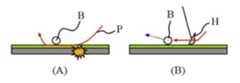
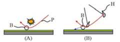
그러나 도 1에서 (A)로 나타낸 골프 필드 잔디와 도 1에서 (B)로 나타낸 골프 연습장 고무 매트의 특성 차이에 따라, 연습장에서는 볼이 잘 맞고 거리도 잘 나가는데 필드만 나가면 이상하게 안맞는다고 불만을 토로하는 사람이 많다. 필드의 잔디는 도 1에서 (A)로 나타낸 것과 같이 풀이 길고 잎이 넓고 힘이 없는 촘촘하지 않고 넓고 퍼져 자라 대부분 공이 좀 가라앉아 있다. 반면 연습장 매트의 인조 잔디는 도 1에서 (B)로 나타낸 것과 같이 플라스틱 조각으로 짧고 빳빳하여 공이 떠 있게 된다. 따라서, 매트에서는 시각적으로 공이 전부 보이지만 필드에서는 잔디에 가라앉아 보여 시각적으로 다른 느낌을 주게 된다. 또한 아마추어 골퍼들이 연습장에서 연습하는 모습을 보면 뒷땅을 치는 사람들이 많은 데, 뒷땅의 충격으로 손목,팔꿈치,어깨 등에 통증이 오게 되는 것은 물론, 심할 경우 부상을 유발하게 된다.However, depending on the difference in the characteristics of the golf field lawn shown in (A) in FIG. 1 and the golf course golf course mat shown in (B) in FIG. 1, the ball fits well in the driving range and the distance is good. There are many people who do. The grass of the field is a grass with a long grass, a broad leaf, a weak grass, a dense, broad and spreading grass as shown by (A) in FIG. On the other hand, the artificial grass of the practice mat is short and stiff as a piece of plastic, as shown in Fig. 1 (B), and the ball floats. Thus, while the mat can see all of the ball visually, the field sits on the grass and gives a different visual impression. In addition, amateur golfers practicing in the practice field have a lot of people hitting the back ground. The impact of the back ground not only brings pain to the wrists, elbows and shoulders, but also causes serious injuries.
한편, 연습장의 매트는 바닥이 딱딱하여 도 2에 나타낸 것과 같이 뒷땅이 나와도 클럽이 앞으로 미끄러지며 공을 타격하게 되어 볼이 잘 맞는것으로 착각하게 된다. 그러나 필드는 잔디 밑이 흙이라 뒷땅이 발생하면 도 3에 나타낸 것과 같이 클럽 헤드가 미끄러지지 못하고 땅을 파고 들어가 공을 치지 못하고 땅을 퍼내고 말아 비거리가 짧아진다.On the other hand, the mat of the driving range is hard, and as shown in FIG. 2, even if the back ground comes out, the club slides forward and strikes the ball. However, when the ground is under the grass, when the back ground occurs, the club head does not slip as shown in FIG. 3, and the ground can not be hit, the ball can not hit, and the ground is shaved.
이와 같은 실제 필드에서와 연습장 매트에서의 차이를 줄이기 위해서는 도 4에 나타낸 것과 같은 다운 블로 샷(down blow) 샷을 해야 한다. 다운블로 샷은 볼을 먼저 하향 타격하는 것으로, 디봇(divot)은 골프공 앞쪽에 남는 것이 바람직하다. 반면에 골프공 뒷쪽에 디봇(divot)이 남는 경우는 클럽 헤드가 땅부터 가격하는 경우로서, 체중 이동이 되지 않아 오른쪽에 체중이 남아있거나 클럽을 빨리 언코킹하는 이와 같은 뒷땅(fat shot, duff)이 발생할 수 있다.In order to reduce the difference between the actual field and the practice mat, it is necessary to perform a down blow shot as shown in Fig. The down-blow shot first hits the ball downwards, and the divot is preferably left in front of the golf ball. On the other hand, if a divot is left behind on a golf ball, the club head will land on the ground. If the player does not move his or her weight and has weight left on his / Can occur.
한편, 도 5에 나타낸 것과 같이 골프공의 윗부분을 가격하는 탑핑(topping)의 경우, 골프공의 탄도가 낮아 스핀이 적고 제거리보다 더 나가거나 낮게 굴러가는 미스샷(일명 뱀샷)이 발생하게 된다.On the other hand, as shown in FIG. 5, in the case of topping that tops the golf ball, a golf ball has a low trajectory, resulting in a small number of spins and a miss shot (aka snake shot) .
또한, 도 6에 나타낸 것과 같은 일명 도끼샷은 탑핑과 거의 유사한 스윙이나, 탑핑이 스윙의 최저점이 골프공의 중간 부근인데 비하여 도끼샷의 경우 스윙의 최저점이 골프공 아래의 바닥을 충격한다는 점에서 차이가 있다. 이 경우 역시 부상의 위험이 많은 경우이다.Also, in the case of the ax shots, the lowest point of the swing impacts the floor under the golf ball, while the ax shots as shown in Fig. 6 are almost similar to the swing, There is a difference. In this case too, there is a high risk of injury.
통상적인 기존 골프 스윙 매트는 뒷땅이 발생하여도 클럽헤드가 매트 바닥에서 미끄러지며 공을 가격하므로 잔디에서 보다 비거리가 더 나오게 되는 문제점 발생하지만, 통상적인 기존 골프 스윙 매트에서는 뒷땅 여부를 알 수가 없었다.Conventional conventional golf swing mats have problems in that the club head slides on the mat bottom even when the back ground occurs, and the golf ball is priced higher than the grass. However, the conventional golf swing mat does not know whether or not the back ground exists.
이러한 문제점을 해결하여 연습용 매트에서 뒷땅 여부를 알 수 있는 종래 기술로는 도 7에 나타낸 것과 같이 매트위에 마찰열에 의해 색깔이 변하는 감열지를 부착하여, 샷을 하면 클럽헤드가 마찰하고 지나간 자국을 육안으로 확인할 수 있도록 하는 기술이 제안되었었다. 그러나, 사용 횟수가 매우 제한적이고 재사용이 안되므로 불편하므로, 연습용으로 계속 사용하는 용도로는 부적합하고 분석용으로 몇차례 사용 가능한 수준에 머물고 있다.In order to solve this problem, in the related art in which the back surface of the practice mat can be detected, as shown in FIG. 7, a thermosensitive paper whose color is changed by frictional heat is attached on the mat, A technique has been proposed that allows the user to confirm the information. However, since the number of times of use is very limited and it is inconvenient because it can not be reused, it is not suitable for continuous use for practice and remains at a level that can be used several times for analysis.
또 다른 기존 기술로 도 8에 나타낸 것과 같이 슬라이드 매트를 이용하여, 클럽 헤드가 매트를 가격하면 슬라이드 매트가 볼 진행 방향으로 슬라이드 됨으로써 천연 잔디 같은 피드백을 제공하는 방식이 있다. 이 경우, 매트가 슬라이드 함으로 뒷땅을 쳤을때 가해지는 충격을 방지할 수 있는 장점이 있으나, 볼 뒤쪽을 가격하면 매트가 움직이기 시작하므로 매트가 고정되어 있는 경우보다 훨씬 적은 힘으로 공을 가격하게 되어 비거리 손해를 보게되며, 어느 정도 뒷땅을 쳤는지 확인할 수 없고 매트가 이동하므로 처음에 다소 어색하게 느껴진다는 문제점이 있었다.Another conventional technique is to use a slide mat as shown in FIG. 8, and when the club head is matted, the slide mat slides in the ball advancing direction to provide feedback such as natural grass. In this case, there is an advantage in that the impact applied when the back of the ball is hit by the slide of the mat is advantageous, but since the mat starts to move at the back of the ball, the ball is priced at a much lower force than when the mat is fixed I was not able to confirm how much I had hit the back ground, and I felt a bit awkward at first because the mat moved.
한편, 연습용 매트에서 잔디의 느낌을 주기 위한 방향으로 접근하는 또 다른 기존 기술로, 도 9에 나타낸 것과 같이 인조 잔디 아래 젤 재질의 블록을 두어 매트 타격시 볼 진행 방향으로 클럽헤드가 잘 미끄러지지 않도록 저항을 주는 방식 또는 도 10에 나타낸 것과 같이 매트 밑에 마그네틱 필드 반발력에 의해 띄워져 있는 고무 매트를 가격하여 천연 잔디의 피드백을 주려는 방식이 제안되었다. 그러나 상기 두 방식은 모두 단순히 천연 잔디의 느낌을 주려는 고무 매트의 구조에 관한 것에 불과한 것으로, 디봇 정보의 정량적 피드백 기능은 없다는 문제점이 있었다.Meanwhile, as another conventional technique of approaching in the direction for giving a feeling of lawn to the practice mat, a block of a gel material under artificial turf is placed as shown in Fig. 9 so as to prevent the club head from slipping smoothly Or a method of giving feedback to the natural grass by charging a rubber mat floated by the magnetic field repulsive force under the mat as shown in FIG. 10 has been proposed. However, both of the above methods are merely related to the structure of a rubber mat which is intended to give a feeling of natural grass, and there is a problem that there is no quantitative feedback function of the dibot information.
또 다른 관련 선행 발명으로는, 하기 특허문헌 1의 "골프 스윙 연습 장치(대한민국 등록실용신안 제20-0323906호)에 개시된 것과 같이, 내부에 일정 공간을 갖는 복수개의 홈들을 구비하는 바닥과, 홈 내부의 공간 내에 장착되며, 수직 방향으로 세워진 제1 상태 및 골프 클럽 헤드의 타격에 의해 수평 방향으로 누워지는 제2 상태를 가질 수 있는 복수개의 감지핀들과, 감지핀들에 대응되도록 배치되어서 대응되는 감지핀의 상태에 따라 점등 여부가 결정되는 복수개의 발광 다이오드들과, 그리고 감지핀의 상태에 따라 발광 다이오드를 점등시키거나 점멸시키기 위한 제어 회로를 포함하는 구성이 있다. 이러한 기존 선행 발명의 경우, 클럽 헤드가 감지핀을 타격시 이와 연결된 발광 다이오드가 점등되게 함으로서 각 발광 다이오드의 점등 상태로 클럽 헤드의 스윙 경로 및 임팩트 순간의 클럽 헤드 페이스의 상태(목표 방향에 대해 직각, 열림, 닫힘)를 파악할 수 있다는 효과가 있으나, 감지핀을 사용하는 구성 상의 한계에 의하여 스윙에 방해가 될 수 밖에 없으며, 단순하게 스윙 궤적의 방향만을 감지할 수 있을 뿐, 뒷땅과 관련되는 상하 방향의 타격력은 전혀 감지할 수 없다는 문제점이 있었다.As another related prior art, there is disclosed a golf swing practice apparatus (Korean Utility Model Registration No. 20-0323906) of the following
본 발명은 상기한 기존 발명들의 문제점을 해결하여, 골프공의 유무 및 위치, divot 위치, 깊이, 방향 등 골프 클럽이 매트를 가격할 때 얻을 수 있는 각종 정보를 감지하여 사용자에게 표시해 줄 수 있는 디봇 검출 골프 스윙 매트를 제공하여, 디봇이 공 앞쪽에 생기도록 올바른 체중 이동을 하며 의식적으로 스윙 연습을 하여 샷메이킹 능력이 향상되는 것은 물론, 연습장과 필드에서의 차이를 줄일 수 있도록 하는 것을 그 과제로 한다.Disclosure of Invention Technical Problem [7] The present invention has been made to solve the above-mentioned problems of the prior art, and it is an object of the present invention to provide a system and method for detecting a golf ball, The golf swing mats are provided so that the correct weight shifts are made in front of the ball so that the dives can perform swing exercises consciously to improve the shot making ability as well as to reduce differences in the practice field and field. do.
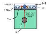
상기한 과제를 달성하기 위하여 본 발명의 디봇 검출 골프 스윙 매트에 관한 것으로, 상측에 골프공(B)이 안착 될 수 있는 인조 잔디(111)가 설치되어 있는 타격 매트(110);와, 상기 타격 매트(110)의 하측에 설치되며, 상기 타격 매트(110)를 통하여 전달되는 클럽 헤드(H)의 타격을 어레이(Array) 형태로 배열된 센서를 통하여 측정하는 디봇 검출 센서 어레이부(120);와, 상기 디봇 검출 센서 어레이부(120)에서 감지된 상기 클럽 헤드(H)의 타격 정보를 계산하는 제어부(130);와, 상기 타격 매트(110)의 후방 일 측면에 설치되며, 상기 골프공(B)의 위치를 지정하는 골프공 위치 지정부(150);와, 상기 클럽 헤드(H)의 타격정보와 상기 골프공(B) 위치를 표시하는 디스플레이부(140);를 포함하여 구성되는 것을 특징으로 한다.In order to accomplish the above object, the present invention provides a golf swing mat for detecting a dibot, comprising: a striking mat (110) having a synthetic grass (111) on which a golf ball (B) A dibot detection
또한, 상기 디봇 검출 센서 어레이부(120)는, 상기 센서가 상기 클럽 헤드(H)의 스윙 방향으로부터 수직 방향에 1차원적으로 배열되거나 상기 클럽 헤드(H)의 스윙 방향으로부터 수직 방향 및 상기 클럽 헤드(H)의 스윙 방향에 2차원적으로 배열되어 구성되는 것을 특징으로 하고, 상기 디스플레이부(140)는, 엘이디(LED)가 상기 클럽 헤드(H)의 스윙 방향을 따라 1차원적으로 배열된 엘이디 어레이 디스플레이(141) 또는 패널 형태의 엘씨디 패널 디스플레이(142) 중 어느 하나 이상을 포함하여 구성되는 것을 특징으로 하며, 상기 골프공 위치 지정부(150)는, 상기 클럽 헤드(H)의 접촉 위치를 감지하여 상기 제어부(130)로 전달하도록 터치 스크린부(151), 버튼 스위치부(152) 또는 근접 스위치부(153) 중 어느 하나 이상을 포함하여 엘이디 공표시를 좌/우로 이동시켜 상기 골프공(B)의 위치를 결정하는 것을 특징으로 한다.In addition, the dibot detection
또한, 상기 터치 스크린부(151)는, 상기 클럽 헤드(H)의 스윙 방향을 따라 1차원적으로 배열되는 터치 센서들로 구성되고, 상기 제어부(130)는 상기 터치 스크린부(151)에 접촉하는 상기 클럽 헤드(H)의 접촉 위치에 따라 상기 골프공(B)의 위치를 결정하는 것을 특징으로 한다.The
또한, 상기 제어부(130)는 상기 클럽 헤드(H)의 타격 정보에 따라 상기 디봇의 위치, 디봇의 깊이, 디봇의 방향 중 어느 하나 이상을 포함하는 디봇 정보를 생성하는 것을 특징으로 하고, 상기 제어부(130)에 더 연결되며, 상기 디봇 정보를 음성으로 안내하는 음성 출력부(160);와, 상기 제어부(130)에 더 연결되며, 상기 골프공(B)의 위치를 촬영하여 상기 제어부(130)로 전달하는 카메라부(171);와, 기 제어부(130)에 더 연결되며, 상기 디봇 검출 센서 어레이부(120)의 온도 특성을 보정하기 위한 온도를 측정하는 온도 센서부(172);와, 기 제어부(130)에 더 연결되며, 광고를 표시하는 광고 표시부(180); 를 더 포함하여 구성되는 것을 특징으로 한다.The
또한, 상기 제어부(130)에 더 연결되며, 상기 클럽 헤드(H)의 타격 정보를 골프 시뮬레이션 시스템 또는 사용자의 휴대용 단말기로 유선 또는 무선 방식으로 전달하는 유무선 송수신부(170); 를 더 포함하여 구성되는 것을 특징으로 한다.A wired / wireless transmitting / receiving unit 170 further connected to the
또한, 상측에 골프공(B)이 안착 될 수 있는 인조 잔디(111)가 설치되어 있는 타격 매트(110);와, 기 타격 매트(110)의 하측에 설치되며, 상기 타격 매트(110)를 통하여 전달되는 클럽 헤드(H)의 타격을 어레이(Array)로 배열된 센서를 통하여 측정하는 디봇 검출 센서 어레이부(120);와, 상기 디봇 검출 센서 어레이부(120)에서 전달된 상기 클럽 헤드(H)의 타격 정보를 계산하는 제어부(130);와, 기 클럽 헤드(H)의 타격정보와 상기 골프공(B) 위치를 표시하는 디스플레이부(140);를 포함하여 구성되되, 기 골프공(B)을 상기 타격매트(110)의 상부에 올려놓은 상태에서 사용자가 상기 골프공(B)을 소정의 시간동안 밟으면, 상기 골프공(B)을 위치를 상기 디봇 검출 센서 어레이부(120)가 감지하여 상기 제어부(130)에서 공의 위치를 결정하는 것을 특징으로 한다.A
또한, 상기 디봇 검출 센서 어레이부(120)는, 탄성재질로 이루어지고, 내측에는 상기 클럽 헤드(H)의 스윙 방향으로부터 수직 방향에 다수개의 제1 관통홀(122a)이 통공되어 있는 본체플레이트(122)와, 기 본체플레이트(122)의 일측에 형성되되, 상기 제1 관통홀(122a)과 대응되는 위치에 제1 발광센서(123a)가 구비되는 제1 발광부(123)와, 상기 본체플레이트(122)의 타측에 형성되되, 상기 제1 관통홀(122a)과 대응되는 위치에 형성되어 상기 제1 관통홀(122a)을 통과한 상기 제1 발광부(123)로부터 발생되는 빛을 인식하는 제1 수광센서(124a)가 구비되는 제1 수광부(124a)와, 상기 제1 발광부(123) 및 제1 수광부(124)와 연결되어 상기 제1 관통홀(122a)을 통과하는 빛의 양을 측정하여 상기 제어부(130)로 전달하는 센서 신호 검출부(121)로 구성되는 것을 특징으로 한다.The dibot detection
또한, 상기 본체플레이트(122)에는 각각의 상기 제1 관통홀(122a)로부터 직교방향으로 다수개의 제2 관통홀(122b)이 통공형성되고, 상기 본체플레이트(122)의 말단측에 형성되되, 상기 제2 관통홀(122b)과 대응되는 위치에 제2 발광센서(125a)가 구비되는 제2 발광부(125)와, 상기 본체플레이트(122)의 선단측에 형성되되, 상기 제2 관통홀(122b)과 대응되는 위치에 형성되어 상기 제2 관통홀(122b)을 통과한 상기 제2 발광부(125)로부터 발생되는 빛을 인식하는 제2 수광센서(126a)가 구비되는 제2 수광부(126)가 형성되어, 상기 센서 신호 검출부(121)가 상기 제2 관통홀(122b)을 통과하는 빛의 양을 측정하여 상기 제어부(130)로 전달하는 것을 특징으로 한다.A plurality of second through
본 발명에 의하는 경우, 골프공의 유무 및 위치, divot 위치, 깊이, 방향 등 골프 클럽이 매트를 가격할 때 얻을 수 있는 각종 정보를 감지하여 사용자에게 표시해 줄 수 있는 디봇 검출 골프 스윙 매트를 제공하여, 디봇이 공 앞쪽에 생기도록 올바른 체중 이동을 하며 의식적으로 스윙 연습을 하여 샷메이킹 능력이 향상되는 것은 물론, 연습장과 필드에서의 차이를 줄일 수 있도록 하는 것을 그 과제로 한다.According to the present invention, it is possible to provide a dibot detection golf swing mat that can detect and display to the user various information that can be obtained when a golf club price a mat, such as the presence or absence of a golf ball, the position, depth, Therefore, it is a task to reduce the difference in the practice field and the field as well as improve the shot-making ability by consciously practicing the swing by performing the correct weight shift so that the divot is in front of the ball.
도 1: 골프 필드 잔디와 연습장 매트의 차이를 나타내는 도면.
도 2: 연습장의 뒷땅(fat shot, duff)의 경우를 나타내는 도면.
도 3: 골프 필드의 뒷땅(fat shot, duff)의 경우를 나타내는 도면.
도 4: 다운 블로 샷(down blow shot)의 경우를 나타내는 도면.
도 5: 탑핑(topping)의 경우를 나타내는 도면.
도 6: 도끼샷의 경우를 나타내는 도면.
도 7: 감열지를 이용한 기존 발명의 일 실시예를 나타내는 도면.
도 8: 슬라이드 매트를 이용하는 기존 발명의 일 실시예를 나타내는 도면.
도 9: 젤 블록을 이용하는 기존 발명의 일 실시예를 나타내는 도면.
도 10: 마그네틱 필드를 이용하는 기존 발명의 일 실시예를 나타내는 도면.
도 11: 본 발명의 일 실시예에 의한 디봇 검출 골프 스윙 매트의 구성을 나타내는 상면도.
도 12: 본 발명의 일 실시예에 의한 디봇 검출 골프 스윙 매트의 구성을 나타내는 측단면도.
도 13: 본 발명의 일 실시예에 의한 디봇 검출 골프 스윙 매트의 구성을 나타내는 블럭 다이어그램.
도 14: 본 발명의 제 1 실시예에 의한 디봇 검출 골프 스윙 매트의 구성을 나타내는 모식도.
도 15: 본 발명의 제 1 실시예에 의한 디봇 검출 골프 스윙 매트의 점등 방식을 나타내는 도면.
도 16: 본 발명의 제 2 실시예에 의한 디봇 검출 골프 스윙 매트의 구성을 나타내는 모식도.
도 17: 본 발명의 제 2 실시예에 의한 디봇 검출 골프 스윙 매트의 디봇 검출 센서 어레이부의 센서 측정값의 경우를 예시하여 나타내는 도면.
도 18: 본 발명의 제 2 실시예에 의한 디봇 검출 골프 스윙 매트의 디봇 검출 센서 어레이부의 센서 측정값을 3차원적으로 표현한 도면.
도 19: 본 발명의 제 3 실시예에 의한 디봇 검출 골프 스윙 매트의 엘씨디 패널 디스플레이의 표현 화면을 나타내는 도면.
도 20: 본 발명의 제 1 실시예에 의한 디봇 검출 골프 스윙 매트의 골프공 위치 지정 작동을 나타내는 도면.
도 21: 본 발명의 제 1 실시예에 의한 디봇 검출 골프 스윙 매트의 또 다른 골프공 위치 지정 작동을 나타내는 도면.
도 22: 본 발명의 디봇 검출 골프 스윙 매트을 적용한 스크린골프장의 모습을 보인 도면.
도 23: 본 발명의 제 4 실시예에 의한 디봇 검출 골프 스윙 매트의 구성 중 디봇 검출 센서 어레이부의 구성을 보인 모식도.
도 24: 본 발명의 제 4 실시예에 의한 디봇 검출 골프 스윙 매트의 구성 중디봇 검출 센서 어레이부의 구성을 보인 구성도.
도 25: 본 발명의 제 4 실시예에 의한 디봇 검출 골프 스윙 매트의 구성을 보인 평면도 및 단면도
도 26: 본 발명의 제 5 실시예에 의한 디봇 검출 골프 스윙 매트의 구성 중디봇 검출 센서 어레이부의 구성을 보인 구성도.
도 27: 본 발명의 제 5 실시예에 의한 디봇 검출 골프 스윙 매트의 구성 중제1, 2 관통홀의 다양한 실시예를 보인 실시예도
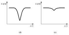
도 28: 본 발명의 제 5 실시예에 의한 디봇 검출 골프 스윙 매트의 충격여부에 따른 수광량의 차이를 보인 그래프.
도 29: 본 발명의 제 5 실시예에 의한 디봇 검출 골프 스윙 매트의 충격강도에 따른 수광량의 변화를 보인 그래프.
도 30: 본 발명의 제 5 실시예에 의한 디봇 검출 골프 스윙 매트의 충격시간에 따른 수광량의 변화를 보인 그래프.BRIEF DESCRIPTION OF THE DRAWINGS Figure 1: Drawings illustrating the difference between a golf field lawn and a practice mat.
2 shows a case of a fat shot (duff) of a driving range.
3 shows a case of a fat shot (duff) of a golf field.
4 shows a case of a down blow shot.
5 is a view showing a case of topping;
6 is a view showing the case of an ax shot;
7 is a view showing one embodiment of the existing invention using thermal paper;
8 shows an embodiment of the existing invention using a slide mat.
9 shows an embodiment of the existing invention using a gel block.
10 shows an embodiment of an existing invention using a magnetic field;
11 is a top view showing a configuration of a golf swing mat according to an embodiment of the present invention.
12 is a side sectional view showing a configuration of a golf swing mat for detecting a divot according to an embodiment of the present invention;
FIG. 13 is a block diagram showing the configuration of a golf swing mat for detecting a debot according to an embodiment of the present invention.
14 is a schematic diagram showing the configuration of a golf swing mat for detecting a divot according to the first embodiment of the present invention.
15 is a view showing a lighting method of a golf swing mat for detecting a divot according to the first embodiment of the present invention.
16 is a schematic diagram showing the configuration of a golf swing mat for detecting a divot according to a second embodiment of the present invention;
Fig. 17 is a diagram illustrating the case of sensor measurement values of the dibot detection sensor array unit of the golf swing mat according to the second embodiment of the present invention. Fig.
FIG. 18 is a diagram three-dimensionally representing the sensor measurement values of the dibot detection sensor array unit of the golf swing mat according to the second embodiment of the present invention.
19 is a view showing an expression screen of an LCD panel display of a golf swing mat according to a third embodiment of the present invention.
20 shows a golf ball positioning operation of a divot-detecting golf swing mat according to the first embodiment of the present invention;
21 shows another golf ball positioning operation of a divot detecting golf swing mat according to the first embodiment of the present invention;
22 is a view showing a screen golf course applying the divot detection golf swing mat of the present invention.
23 is a schematic diagram showing a configuration of a divot detection sensor array unit in a configuration of a golf swing mat according to a fourth embodiment of the present invention.
Fig. 24 is a configuration diagram showing the configuration of the divot detection sensor array portion of the configuration of the golf swing mat according to the fourth embodiment of the present invention; Fig.
Fig. 25 is a plan view and a cross-sectional view showing the configuration of a golf swing mat according to a fourth embodiment of the present invention;
Fig. 26 is a configuration diagram showing a configuration of a dibot detection sensor array unit in a configuration of a golf swing mat according to a fifth embodiment of the present invention; Fig.
Fig. 27: Configuration of a golf swing mat for detecting a divot according to a fifth embodiment of the present invention.
28 is a graph showing the difference in the amount of received light according to whether or not the golf swing mat is impacted by the dynamic detecting method according to the fifth embodiment of the present invention.
29 is a graph showing a change in the amount of received light according to the impact strength of the golf swing mat according to the fifth embodiment of the present invention.
30 is a graph showing a change in the amount of received light according to the impact time of the golf swing mat according to the fifth embodiment of the present invention.
이하에서는 첨부된 도면을 참조로 하여, 본 발명의 일 실시 예에 따른 디봇 검출 골프 스윙 매트를 상세히 설명한다. 우선, 도면들 중, 동일한 구성요소 또는 부품들은 가능한 한 동일한 참조부호로 나타내고 있음에 유의하여야 한다. 본 발명을 설명함에 있어, 관련된 공지 기능 혹은 구성에 관한 구체적인 설명은 본 발명의 요지를 모호하지 않게 하기 위하여 생략한다.DETAILED DESCRIPTION OF THE PREFERRED EMBODIMENTS Hereinafter, a golf swing mat according to an embodiment of the present invention will be described in detail with reference to the accompanying drawings. First, it should be noted that, in the drawings, the same components or parts are denoted by the same reference numerals whenever possible. In describing the present invention, a detailed description of known functions and configurations incorporated herein will be omitted so as to avoid obscuring the subject matter of the present invention.
본 발명의 일 실시 예에 따른 디봇 검출 골프 스윙 매트(100)는 크게 도 11 내지 도 13에 나타낸 것과 같이, 타격 매트(110), 디봇 검출 센서 어레이부(120), 제어부(130), 디스플레이부(140) 및 골프공 위치 지정부(150)를 포함하여 구성되는 것을 특징으로 한다.11 to 13, the divot detection golf swing mat 100 according to an embodiment of the present invention includes a
먼저, 타격 매트(110)에 관하여 설명한다. 상기 타격 매트(110)는 도 11 및 도 12에 나타낸 것과 같이, 상측에 골프공(B)이 안착될 수 있는 인조 잔디(111)가 설치되어 있다. 한편, 상기 타격 매트(110)는 계속되는 클럽 헤드(H)와의 마찰로 인해 상기 인조잔디(111)가 마모되어 상기 인조잔디(111) 높이가 낮아지게 되면 골프공 타격감이 나빠지므로, 상기 인조잔디(111)가 접착되어있는 상기 타격매트(110)만을 교체하여 장착할 수 있도록 구성되는 것이 바람직하다.First, the
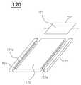
다음으로, 디봇 검출 센서 어레이부(120)에 관하여 설명한다. 상기 디봇 검출 센서 어레이부(120)는 도 11 및 도 12에 나타낸 것과 같이, 상기 타격 매트(110)의 하측에 설치되며, 상기 타격 매트(110)를 통하여 전달되는 클럽 헤드(H)의 타격을 어레이(Array) 형태로 배열된 센서를 통하여 감지하는 기능을 가진다.Next, the dibot detection
이 경우, 상기 센서는 FSR(Force Resistive Sensor), 압전소자, 충격센서, 정전센서, 근접센서, 인장력센서(고무매트가 휘어지는 정도 검출), 로드셀, 스트레이게이지, 광센서 등 다양한 방식 중 어느 하나로 구성되는 것이 가능하며 본 발명은 특정 센서 방식으로 한정하지 않는다. 이러한 센서 방식 선정시 센서 응답 속도와 온도 특성이 매우 중요하다. 이와 같은 센서의 온도 특성을 보상하여 보정하는 것이 가능하도록, 도 13에 나타낸 것과 같이 상기 제어부(130)에 더 연결되며 상기 디봇 검출 센서 어레이부(120)의 온도 특성을 보정하기 위한 온도를 측정하는 온도 센서부(172)를 더 포함하여 구성되는 것이 바람직하다. 실외에 설치된 골프 매트는 -20도~50도 정도의 온도에서 동작 가능해야 하나 통상 센서는 온도에 따라 반응 정도가 달라질 수 있음으로 절대적인 충격량에 센서가 동일하게 반응하도록 온도를 감지하여 실시간으로 센서 값을 보정하여 사용하는 것이 바람직하다.In this case, the sensor may be configured in any one of a variety of ways such as a force resistive sensor (FSR), a piezoelectric element, an impact sensor, an electrostatic sensor, a proximity sensor, a tensile force sensor And the present invention is not limited to a specific sensor system. The sensor response speed and temperature characteristics are very important when selecting this type of sensor. In order to compensate for the temperature characteristic of such a sensor, a temperature for correcting the temperature characteristic of the diboscope detection
또한, 상기 센서의 특성에 따라, 충격량, 압력, 힘 또는 길이의 변화량에 해당하는 아날로그 전압 또는 전류의 형태로 출력된 순수한 센서의 출력을 디지털 데이터로 변환하기 위하여 도 13에 나타낸 것과 같이 센서신호 검출부(121)를 더 포함하여 구성되는 것도 가능하다. 상기 센서신호 검출부(121)는 통상적으로 신호필터회로, 신호증폭기, AD변환기를 통하여 디지털 값으로 변환되도록 구성된다. 상기 센서신호 검출부(121)를 구현하는 기술은 센서 측정 분야에서 널리 알려져 실시되고 있는 수준의 기술이므로, 상세한 설명은 생략한다.13, in order to convert an output of a pure sensor output in the form of an analog voltage or current corresponding to the amount of change in the amount of impact, pressure, force, or length according to the characteristics of the sensor into digital data, (121) as shown in FIG. The sensor
한편, 상기 디봇 검출 센서 어레이부(120)를 구성하는 센서의 구성은 도 14에 나타낸 제 1실시예와 같은 1D 또는 도 16에 나타낸 제 2 실시예와 같은 2D형태로 배열하여 사용할 수 있다. 즉, 상기 디봇 검출 센서 어레이부(120)는, 도 14에 나타낸 제 1실시예와 같이 상기 센서가 상기 클럽 헤드(H)의 스윙 방향을 따라 1차원적으로 배열되거나, 도 16에 나타낸 제 2 실시예와 같이 상기 타격 매트(110)와 평행한 평면으로 2차원적으로 배열되어 구성되는 것이 가능하다. 이와 같이 2D 배열인 경우 디봇의 방향도 검출할 수 있는 장점이 있으나 센서 처리부가 복잡하고 가격이 높은 단점이 있다. 단위 센서의 크기를 작게 할수록 길이 검출 분해능은 높아진다.The configuration of the sensors constituting the dibot detection
앞서 설명한 상기 타격 매트(110)와 상기 디봇 검출 센서 어레이부(120)는 분리가 가능한 구조일수도 있으나 센싱 감도를 향상시키기 위해 상기 타격 매트(110) 하단에 상기 디봇 검출 센서 어레이부(120)가 접착되는 형태, 상기 타격 매트(110) 내부에 상기 디봇 검출 센서 어레이부(120)가 빌트인(built-in)되는 형태 또는 센싱 원리상 상기 타격 매트(110) 자체가 상기 디봇 검출 센서 어레이부(120) 역할을 하는 형태일수도 있다.Although the
다음으로, 제어부(130)에 관하여 설명한다. 상기 제어부(130)는 도 13에 나타낸 것과 같이, 상기 디봇 검출 센서 어레이부(120)에서 전달된 상기 클럽 헤드(H)의 타격 정보를 디스플레이부(140)에 표시하도록 하는 기능을 가진다. 즉, 상기 제어부(130)는 상기 클럽 헤드(H)의 타격 정보에 따라 상기 디봇의 위치, 디봇의 깊이, 디봇의 방향 중 어느 하나 이상을 포함하는 디봇 정보를 생성한 후, 이를 상기 디스플레이부(140) 또는 후술할 음성 출력부(160) 등을 통하여 사용자에게 표시하여 피드백 하는 기능을 가지도록 구성된다.Next, the
또한, 상기 제어부(130)는 골프공 위치 지정부(150)에서 조작한 상기 골프공(B)의 위치를 특정하여 상기 디스플레이부(140)에 함께 표시하는 기능도 가지는 것이 가능하다.The
다음으로, 디스플레이부(140)에 관하여 설명한다. 상기 디스플레이부(140)는 도 13에 나타낸 것과 같이 상기 제어부(130)에 연결되어 상기 클럽 헤드(H)의 타격 정보(즉, 디봇의 위치, 디봇의 깊이, 디봇의 방향 중 어느 하나 이상을 포함하는 디봇 정보)를 표시하여 사용자에게 피드백하는 기능을 가진다. 이 경우, 상기 디스플레이부(140)는 도 14에 나타낸 제 1실시예와 같이 엘이디(LED)가 상기 클럽 헤드(H)의 스윙 방향을 따라 1차원적으로 배열된 엘이디 어레이 디스플레이(141) 또는 도 19에 나타낸 제 3 실시예와 같이 패널 형태의 엘씨디 패널 디스플레이(142) 중 어느 하나 이상을 포함하여 구성되는 것이 가능하다.Next, the
다음으로, 골프공 위치 지정부(150)에 관하여 설명한다. 상기 골프공 위치 지정부(150)는 타격을 위하여 상기 타격 매트(110) 위에 놓여지는 상기 골프공(B)의 위치를 지정하는 수단을 제공한다. 이 경우, 상기 골프공 위치 지정부(150)를 구현하는 다양한 실시예가 가능하다.Next, the golf ball
그 일 실시예로, 상기 클럽 헤드(H)의 스윙방향을 따라 1차원적으로 배열되는 감압식 구조의 터치스크린부(151)를 상기 타격 매트(110)의 후방 일 측면에 엘이디 어레이 디스플레이(141) 크기에 상응하는 길이만큼 설치하여 상기 클럽 헤드(H)의 접촉 위치로 공의 위치를 특정할 수 있다.A
상기 터치 스크린부(151)는 사용자가 골프 클럽을 들고 서있는 자세로 주로 사용하게 되는 특성을 고려하여, 간단하게 골프 클럽을 터치하는 것만으로도 조작에 필요한 여러 입력을 받아들일 수 있도록 하는 기능을 수행한다.The
이 경우, 상기 터치 스크린부(151)는 도 14에 나타낸 것과 같이 상기 클럽 헤드(H)의 스윙 방향을 따라 1차원적으로 배열되는 터치 센서들로 구성되고, 도 20에 나타낸 것과 같이 사용자는 골프 클럽 헤드로 상기 골프공(B)의 위치에 해당하는 지점의 상기 터치 스크린부(151)에 접촉하면 상기 제어부(130)는 이 위치를 인식하여 도 15의 (A)와 같이 상기 엘이디 어레이 디스플레이(141)에 골프공(B)의 위치에 해당하는 영역 만큼의 엘이디를 점등시켜 공위치를 표시한다. 또 다른 실시예로 도 14와 같이 단수 또는 복수개의 버튼 스위치부(152)를 푸시 조작하거나 단수 또는 복수개의 금속 감지가 가능한 근접 스위치부(153)에 상기 클럽 헤드(H)를 근접시켜 도 15의 (A)에 나타낸 것과 같이, 파란색으로 점등된 것으로 표현된 골프공 위치 표시 엘이디의 위치를 좌우로 이동 조작하여 그 부합된 위치를 상기 골프공(B)의 위치로 지정하는 것도 가능하다.In this case, the
한편, 또 다른 일 실시예로 도 14에 나타낸 것과 같이, 단수 또는 복수 개의 버튼 스위치부(152)를 물리적으로 가압하여 조작하거나 단수 또는 복수 개의 상기 근접 스위치부(153)에 상기 클럽 헤드(H)를 근접시켜 도 15의 (A)에 나타낸 것과 같이, 파란색으로 점등된 것으로 표현된 골프공 위치 표시 엘이디의 위치를 좌,우로 이동 조작하여 그 부합된 위치를 상기 골프공(B)의 위치로 지정하는 것도 가능하다.14, the single or plural button switch portions 152 may be physically pressed or operated, or the single or plural proximity switch portions 153 may be provided with the club head H, The position of the golf ball position indicating LED turned on in blue is shifted to the left and right as shown in (A) of FIG. 15, and the matching position is designated to the position of the golf ball B It is also possible to do.
또한, 또 다른 일 실시예로 도 21에 나타낸 것과 같이, 상기 디스플레이부(140)에 상기 골프공(B)을 놓아야 할 위치를 지정하여 그 연장선상에 해당하는 위치에 상기 골프공(B)을 위치시키는 것도 가능하다. 즉, 일렬상태에서 등간격으로 위치를 정하여 숫자로 표시된 위치 중(숫자의 간격이 공 한 개 간격에 해당된다.) 사용자가 임의로 선택한 “7” 에 해당하는 위치에 상기 골프공(B)을 맞추어 놓는 식이다. 이 경우, 앞서 설명한 공위치 표시와 스위치에 의한 이동 조작이 필요 없으나 공위치를 사용자가 기억하고 있어야 디봇 표시 정보를 바탕으로 뒷땅 여부를 스스로 판정할 수 있게 된다.In another embodiment, as shown in FIG. 21, a position to place the golf ball B on the
한편, 또 다른 실시예로 터치 스크린부(151), 버튼 스위치부(152) 또는 근접 스위치부(153)가 없이도 상기 골프공(B)을 상기 타격매트(110)의 상부에 올려놓은 상태에서 사용자가 상기 골프공(B)을 소정의 시간동안 밟으면, 상기 골프공(B)을 위치를 상기 디봇 검출 센서 어레이부(120)가 감지하여 상기 제어부(130)에서 공의 위치를 결정하는 방식도 가능하다.In another embodiment, in the state where the golf ball B is placed on the upper part of the
또한, 도 13에 나타낸 것과 같이 상기 제어부(130)에 더 연결되며, 상기 디봇 정보를 음성으로 안내하는 음성 출력부(160)를 더 포함하여 구성되는 것이 바람직하다. 즉, 샷의 결과를 “뒷땅”, “굿샷”등 음성으로 전달하여 사용자에게 디봇 검출 정보를 청각적으로 표시하는 것이 목적이다. 또한 사용자에게 사용 방법 안내, 시스템 오류 정보등을 음성메시지로 전달하는 기능을 한다.In addition, as shown in FIG. 13, it is preferable to further include an
한편, 상기 골프공(B)의 위치를 자동적으로 검출하기 위하여, 상기 제어부(130)에 더 연결되며, 상기 골프공(B)의 위치를 촬영하여 상기 제어부(130)로 전달하는사용자의 스윙 동작을 촬영하는 카메라부(171)를 더 포함하여 구성되는 것이 바람직하다. 이 경우, 상기 카메라부(171)는 후술할 유무선 송수신부(170)를 통하여 외부의 골프 시뮬레이션 시스템과 연결되는 경우, 사용자의 스윙 동작 등을 촬영하기 위한 상기 골프 시뮬레이션 시스템의 카메라를 이용하여 구현되는 것도 가능하다.The
또한, 도 13 및 도 14에 나타낸 것과 같이, 상기 제어부(130)에 더 연결되며, 광고를 표시하는 광고 표시부(180)를 더 포함하여 구성되는 것이 바람직하다.In addition, as shown in FIGS. 13 and 14, it is preferable to further include an
한편, 스크린 골프 등과 같은 외부의 골프 시뮬레이션 시스템 또는 특정한 어플리케이션이 설치된 사용자의 휴대용 단말기 등과 연동하여 작동하는 것이 가능할 수 있도록, 본 발명의 디봇 검출 골프 스윙 매트는 도 13에 나타낸 것과 같이, 상기 제어부(130)에 더 연결되며, 상기 클럽 헤드(H)의 타격 정보를 골프 시뮬레이션 시스템 또는 사용자의 휴대용 단말기로 유선 또는 무선 방식으로 전달하는 유무선 송수신부(170)를 더 포함하여 구성되는 것이 바람직하다.In order to enable the golf swing mat to operate in conjunction with an external golf simulation system such as screen golf or a portable terminal of a user installed with a specific application, And a wired / wireless transmitting / receiving unit 170 for transmitting the hitting information of the club head H to the golf simulating system or the portable terminal of the user in a wired or wireless manner.
스크린 골프장에도 고무 매트를 사용하므로 디봇 발생시에 실제 잔디 경우보다 비거리가 더 나가게 되므로 티(Tee)를 사용하는 드라이버 티샷을 제외하면 실제 필드 상황을 반영하지 못하고 있기 때문에 스크린 골프 스코어가 실제 필드에서보다 10타 정도 적게 나오는 것이 일반적인 현상이다. 따라서, 본 발명에서 제안하는 상기 디봇 검출 골프 매트를 스크린 골프와 같은 상기 골프 시뮬레이션 시스템에 적용하면, 전송받은 디봇 정보를 활용하여 스크린 골프 고유의 비거리, 타구 방향 계산 알고리즘에 상기 디봇 정보를 반영하여 보정된 비거리를 계산할 수 있다. 또한 스크린 화면에 공에 대한 디봇 위치,양,방향을 이미지화하여 표시하거나 잔디가 떨어져나가는 이미지도 영상으로 표현하면 사용자에게 생생하고 직관적인 가상현실의 느낌을 제공해 줄 수 있는 장점이 있다. 본 발명에서는 데이터를 송수신하는 목적으로 특정 유무선 통신 방식으로 한정하지 않으며 다양한 인터넷 연결 수단을 포함 할 수 있다.한편, 스크린골프 시스템에 적용할 경우는 스크린골프 시스템의 입출력 장치를 활용할 수 있으므로 본 발명의 구성 요소 중 입출력에 관련되는 상기 디스플레이부(140), 상기 터치 스위치부(150), 상기 음성 출력부(160) 및 상기 카메라부(171)와 같은 구성 요소 중 일부 또는 전부를 스크린골프 시스템의 입출력 장치로 대체하여 사용하는 것이 가능하다.Since the screen golf course also uses a rubber mat, the distance of the tee will not reflect the actual field conditions except for the driver tee that uses the tee because the tee is more distant than the actual turf when the divot occurs. Therefore, the screen golf score is 10 It is a common phenomenon to appear less often. Therefore, when the present invention is applied to the golf simulation system such as screen golf, the golf ball simulation system of the present invention utilizes the transmitted information on the golf ball to reflect the information on the golf ball's own flying distance, Can be calculated. In addition, it displays the image of the position, volume, and direction of the divot on the screen on the screen, or displays the image of the grass falling off the screen, providing users with a vivid and intuitive virtual reality feeling. In the present invention, it is not limited to a specific wired / wireless communication method for the purpose of transmitting / receiving data, and may include various Internet connection means. In the case of applying to a screen golf system, an input / output device of a screen golf system can be utilized. A part or all of components such as the
한편, 상기 유무선송신부(170)를 통해 시스템 상태정보, 고장 진단, 센서 보정(calibration) 및 점검을 수행할 수 있다. 또한 시스템 상태를 확인할 수 있으며 프로그램 업데이트 동작을 수행할 수도 있고, 인터넷 연결 수단을 통해 복수 개의 시스템에 대한 원격관리 기능을 구현할 수 있다.Meanwhile, the system status information, the failure diagnosis, the sensor calibration, and the check can be performed through the wired / wireless transmission unit 170. In addition, the system status can be checked, the program update operation can be performed, and the remote management function for a plurality of systems can be implemented through the Internet connection means.
다음으로, 본 발명의 일 실시예에 의한 디봇 검출 골프 스윙 매트의 작동에 관하여 설명한다.Next, the operation of the divot-detecting golf swing mat according to one embodiment of the present invention will be described.
먼저, 도 14 내지 도 15를 참조하여 가장 단순한 실시예인 본 발명의 제 1 실시예( 1차원 센서 배열/ 1차원 엘이디 어레이 디스플레이)에 의한 디봇 검출 골프 스윙 매트의 작동을 설명한다.First, referring to Figs. 14 to 15, the operation of the first embodiment (one-dimensional sensor array / one-dimensional LED array display) of the present invention, which is the simplest embodiment, will be described.
이 경우, 상기 골프공 위치 지정부(150)는 상기 터치 스크린부(151)를 포함하여 구성되며, 도 20에 나타낸 것과 같이 골프공(B)이 놓인 위치에 해당하는 터치 스크린부(151)를 클럽 헤드로 접촉하여 골프공(B)의 위치를 제어부(130)에서 인식하도록하거나 도14와 같이 단수 또는 복수개의 버튼 스위치부(152)를 푸시 조작하거나 단수 또는 복수개의 상기 근접 스위치부(153)에 상기 클럽 헤드(H)를 근접시켜 골프공(B)의 위치를 제어부(130)에서 인식하도록 하는 것도 가능하다. 한편 카메라부(171)를 통하여 촬영한 상기 골프공(B)의 영상을 통하여 자동으로 골프공(B)의 위치를 제어부(130)에서 인식하도록 수행되는 것도 가능하다. 이와 같이 인식된 상기 골프공(B)의 위치는 엘이디 어레이 디스플레이(141)에 표시된다.(도 15 에서 (A)에 파란색으로 표시)In this case, the golf ball
한편, 상기 골프공(B)의 위치를 지정하는 골프공 위치 지정부를 구현하는 또 다른 방법으로, 도 21에 나타낸 것과 같이, 디스플레이부(140)에 상기 골프공(B)을 놓아야할 위치를 지정하여 그 연장선상에 해당하는 위치에 상기 골프공(B)를 놓는 것도 가능하다. 즉, 일렬로 등간격으로 위치를 정하여 숫자로 표시된 위치 중(숫자의 간격이 공 한 개 간격에 해당된다.) 사용자가 임의로 선택한 "7" 에 해당하는 위치에 상기 골프공(B)을 맞추어 놓는 식이다. 이 경우는 앞서 설명한 공위치 표시와 스위치에 의한 이동 조작이 필요 없으나 공위치를 사용자가 기억하고 있어야 디봇 표시 정보를 바탕으로 뒷땅 여부를 스스로 판정할 수 있게 된다.As shown in FIG. 21, a position where the golf ball B is to be placed may be specified on the
그 후, 사용자가 스윙을 하면, 상기 디봇 검출 센서 어레이부(120)를 통하여 스윙 과정 중 상기 타격 매트(110)에 접촉한 상기 클럽 헤드(H)를 감지한 후,Thereafter, when the user swings, the club head H that has contacted the
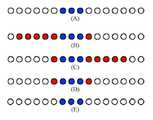
1) 소정 강도 이상으로 접촉한 위치만을 그에 대응하는 상기 엘이디 어레이 디스플레이(141)에 점등하여 표시하거나(도 15의 (B) 내지 (E)에서 각각의 스윙 특성에 따라 다르게 발생할 수 있는 상기 클럽 헤드(H)의 궤적을 각각 붉은색 엘이디로 점등된 것으로 표시하였다. 이 경우, 도 15의 (B)는 타격 후 정상 디봇인 경우를, 도 15의 (C)는 타격 후 뒷땅 디봇인 경우를, 도 15의 (D)는 일명 도끼샷(찍어치기)의 경우를, 도 15의 (E)는 타격 후 탑볼(디봇을 내지 못한 경우)의 경우를 각각 나타낸다.),1), only the position of contact with a predetermined strength or more is displayed on the
2) 접촉 강도에 따라 그에 대응하는 상기 엘이디 어레이 디스플레이(141)에 밝기를 달리하여 점등하여 표시한다.2) The
다음으로, 도 16 내지 도 18을 참조하여 본 발명의 제 2 실시예( 2차원 센서 배열)에 의한 디봇 검출 골프 스윙 매트의 작동을 설명한다.Next, the operation of the golf swing mat according to the second embodiment (two-dimensional sensor arrangement) of the present invention will be described with reference to FIGS. 16 to 18. FIG.
이 경우 역시 전과 동일하게 먼저 골프공(B)의 위치를 인식하여 디스플레이부(140)에 표시한다.In this case as well, the position of the golf ball B is first recognized and displayed on the
그 후, 사용자가 스윙을 하면, 상기 디봇 검출 센서 어레이부(120)를 통하여 스윙 과정 중 상기 타격 매트(110)에 접촉한 상기 클럽 헤드(H)를 감지하는 데, 이 경우는 2차원으로 배열된 각각의 센서에서 측정된 측정값을 배열하여 표시한 도 17에 나타낸 것과 같이, 타원이 디봇 영역을 표시하고 화살표(P)의 방향이 디봇 방향을 나타내게 된다. 오른손잡이의 경우 좌측 방향으로 스윙하므로 디봇 자국은 오른쪽에서 왼쪽 방향으로 발생하며, 도 17 같은 형태의 디봇 자국은 스윙궤도가 인투아웃 즉, 인사이드에서 아웃사이드로 향하는 스윙궤도를 의미한다. 한편, 상기 디봇 검출 센서 어레이부(120)에 2차원으로 배열된 각각의 센서에서 측정된 측정값은 해당 위치의 센서에 전달되는 타격 강도이므로 디봇의 깊이와 비례한다. 따라서, 이 경우 디봇의 위치, 깊이는 물론, 디봇의 방향도 검출하는 것이 가능하다. 한편, 이러한 결과를 효율적으로 전달하기 위해서는 상기 디스플레이부(140)는 2차원 표시가 가능하도록 구현되는 것(예를 들어 dot matrix 표현이 가능한 LED 배열 또는 패널 디스플레이 등)이 바람직하다.Thereafter, when the user swings, the club head H that has contacted the
한편, 도 19를 참조하여 본 발명의 제 3 실시예( 엘씨디 패널 디스플레이를 포함하는 구성)에 의한 디봇 검출 골프 스윙 매트의 작동을 설명한다.On the other hand, referring to Fig. 19, the operation of the third embodiment of the present invention (configuration including an LCD panel display) will be described.
엘이디 어레이 디스플레이(141) 표시는 저렴하고 간단하게 적용할 수 있지만 정보 표현에 한계가 있기 때문에 엘이디 어레이 디스플레이(141)를 대체하여 또는 엘이디 어레이 디스플레이(141)에 더하여 엘씨디 패널 디스플레이(142)를 포함하여 구성될 수 있다. 이 경우, 도 19에 나타낸 것과 같이 스윙 결과를 단면(즉, 디봇 깊이)과 윗면(즉,디봇 모양)에서 바라보는 모습을 이미지로 표시하면 보다 직관적인 정보 전달이 가능할 수 있다. 이 경우, 화면 구성은 메시지 출력, 잔디 위에서 본 이미지 표시, 단면 이미지 표시 등으로 나누어질 수 있으며, Z축 방향(잔디표면에서 지면으로 향하는 방향)의 지면 충격 강도를 게이지 레벨로 별도 시각화 표시할 수도 있다. 한편, 골프연습장에서 사용하는 경우라면 타석번호, 남은 시간, 타격볼 수 등의 타석 관련 정보 또는 CF 광고 등을 LCD 표시부를 통해 함께 나타낼 수 있다.Since the display of the
한편, 앞서 설명한 것과 같이 유무선 송수신부(170)를 통하여 사용자의 휴대용 단말기와 연동하여 작동하도록 하는 경우, 이러한 화면 표시를 사용자의 휴대용 단말기에서 수행하도록 하는 것도 가능하다.On the other hand, in the case of operating in cooperation with the user's portable terminal through the wired / wireless transmission / reception unit 170 as described above, it is also possible to perform such screen display in the portable terminal of the user.
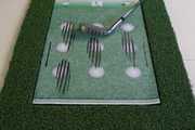
또한, 도 22에 나타낸 것과 같이, 유무선 송수신부(170)를 통하여 스크린 골프 등의 골프 시뮬레이션 시스템과 연동하여 작동하도록 하는 것도 가능하다. 이 경우, 앞서 설명한 것과 같이 경우, 디봇 검출 센서 어레이부(120)이 설치된 타격 매트(110) 이외의 구성은 상기 골프 시뮬레이션 시스템의 입/출력 장치를 이용하여 구현되는 것도 가능하다. 이 경우, 골프공의 위치는 스크린 골프 시스템이 카메라를 통해 알고 있고, 본 발명의 디봇 검출 골프 스윙 매트(100)가 디봇 정보를 검출하여 전송해 주면 스크린 골프 시스템이 공과 디봇 위치를 이미지화하고 상기 디봇 정보의 디봇 강도를 판단하여 디봇이 깊다고 판단되면 뗏장 표시도 해주는 것이 가능하다. 무엇보다 뒷땅 디봇 발생시 비거리 계산시 가중치를 적용하여 스크린 골프 시스템에서 비거리를 줄여 계산하는 것도 가능하다. 이 경우, 본 발명의 디봇 검출 골프 스윙 매트(100)과 스크린골프 시스템은 통신 프로토콜을 사용하여 정보를 교환하거나 제어 명령을 내릴 수 있다. 또한, 본 발명의 디봇 검출 골프 스윙 매트(100)과 스크린골프 시스템은 서로 시간 동기를 맞추고 있으면서, 상기 주제어부(130)는 일정 시간 간격으로 디봇 정보를 내부에 저장하고 있다가 스크린 시스템이 골퍼가 볼을 타격했다고 판단되는 시점의 디봇 정보를 상기 주제어부(130)에 요청하면 해당 디봇 정보를 스크린 시스템에 전송하도록 하는 것이 바람직하다.In addition, as shown in FIG. 22, it is possible to operate in cooperation with a golf simulation system such as screen golf through the wire / wireless transmitting / receiving unit 170. In this case, as described above, the configuration other than the
이하에서는 본 발명의 디봇 검출 골프 스윙 매트(100)의 구성 중 상기 디봇 검출 센서 어레이부(120)의 다른 일실시예에 대하여 설명한다.Hereinafter, another embodiment of the dibot detection
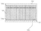
디봇 검출 센서 어레이부(120)는 도 24에 나타낸 것과 같이, 본체플레이트(122), 제1 발광부(123), 제1 수광부(124), 제2 발광부(125), 제2 수광부(126)으로 이루어지는 센서부와 센서신호 검출부(121)에 해당하는 것으로써, 빛(光)의 송수신 및 탄성재질(예컨대, 실리콘 고무판 등)으로 이루어진 본체플레이트(122)의 조합으로 구성된 충격감지센서시스템을 디봇 검출 골프 스윙 매트(100)에 적용한 것이다.24, the divot detection
상기 본체플레이트(122)는 스윙시 바닥 타격의 충격으로 압축되었다가 이내 원상태로 복원되도록 탄성력과 복원력이 우수해야 하며 실외 사용을 고려할 때 온도변화에 무관하게 일정한 물리적 성질을 가져야 하므로 이러한 특성이 우수한 실리콘고무로 제작하는 것이 매우 바람직하다. 일반 유기 고무의 압축 영구 줄음율은 온도 변화에 따라 현저하게 증대되는데 반해 실리콘고무는 -100~250℃ 까지의 넓은 온도 범위에서 탄성 및 복원력이 유지되므로 극심한 조건하에 압축변형이 요구되는 경우에 우수한 성능을 발휘하고, 내후성이 뛰어나 장기간 옥외에 방치하여도 물성 변화가 거의 없으며 내약품성 및 내열수성이 뛰어나 화약 약품이나 물에 장시간 도출되어도 거의 물성 변화가 일어나지 않는 우수한 특성을 가지고 있다.The
한편, 상기 본체플레이트(122)의 내측에는 상기 클럽 헤드(H)의 스윙 방향으로부터 수직 방향에 다수개의 제1 관통홀(122a)이 통공되어 있는 것이 바람직하다.It is preferable that a plurality of first through
또한, 상기 본체플레이트(122)의 일측에는 상기 제1 관통홀(122a)과 대응되는 위치에 다수개의 제1 발광센서(123a)가 구비되는 제1 발광부(123)가 형성되고, 상기 본체플레이트(122)의 타측에는 상기 제1 관통홀(122a)과 대응되는 위치에 형성되어 상기 제1 관통홀(122a)을 통과한 상기 제1 발광부(123)로부터 발생되는 빛을 인식하는 다수개의 제1 수광센서(124a)가 구비되는 제1 수광부(124a)가 형성되며, 상기 제1 발광부(123) 및 제1 수광부(124)와 연결되어 상기 제1 관통홀(122a)을 통과하는 빛의 양을 측정하여 상기 제어부(130)로 전달하는 센서 신호 검출부(121)로 구성되는 것이 바람직하다.A first
이때, 상기 제1 관통홀(122a)의 단면 형상은 원형, 사각형등이 가능하며, 특정 형태로 제한하지 않는다.At this time, the cross-sectional shape of the first through
한편, 상기 제1 발광부(123)는 일반적으로 복수개의 발광센서(예컨대, 적외선LED, 가시광 LED 등)를 사용하며 상기 센서신호 검출부(121)를 통해 상기 제어부(130)에서 on/off 제어를 수행한다.On the other hand, the first
또한, 상기 제2 수광부(124)는 일반적으로 복수개의 수광센서(예컨대, 포토트랜지스터, 포토다이오드 등)를 사용하며 상기 센서신호 검출부(121)를 통해 개별 수광센서의 아날로그 수신 신호는 각각 디지털로 변환되고 제어부로 전달되어 메모리에 저장된다.The second
한편, 상기 제1 발광센서(123a) 또는 상기 제1 수광센서(124a)의 배치시, 편의상 복수개의 광케이블(미도시)을 상기 제1 관통홀(122a) 입구에 위치시켜 원격에 있는 상기 제1 발광센서(123a)의 발광 또는 상기 제1 수광센서(124a)의 빛을 가이드하는 것도 가능하다.Meanwhile, when the first light-emitting
이러한 구성을 통해, 정상상태에서는 상기 제1 발광센서(123a)에서 발생하는 빛이 상기 제1 관통홀(122a)을 따라 상기 제1 수광센서(124a)에 도달하게 된다.With this configuration, in the steady state, the light emitted from the first
만약, 상기 타격매트(110)의 충격으로 상기 본체플레이트(122)가 압축되면, 충격량에 따라 상기 제1 관통홀(122a)의 내부가 좁아 지거나 완전히 막히게 될 수 있으며, 이때 상기 제1 수광센서(124a)에 도달하는 수광량은 줄어들거나 차단되게 된다.If the
한편, 상기 타격매트(110)의 충격이 사라지면, 상기 본체플레이트(122)는 재질 상의 탄성력과 복원력에 의해 상기 제1 관통홀(122a)가 원래 형태로 돌아오게 되는 것을 가능하게 한다.On the other hand, when the impact of the
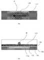
한편, 도 25 에는 상기 본체플레이트(122)와 상기 제1 발광부(123) 및 상기 제1 수광부(124)를 통한 충격 감지 장치를 포함하는 디봇 검출 골프 스윙 매트(100)의 평면도 및 단면도가 도시되어 있다.25 shows a top view and a cross-sectional view of the divot detecting golf swing mat 100 including the
통상 인조 잔디는 직조 방식으로 제작되므로 밑면이 울퉁불퉁하게 되므로 얇은 우레탄 고무 매트층을 접착하여 표면을 매끄럽게 만들고 여분의 충격 흡수 역할도 생긴다.Since artificial turf is generally made by weaving method, the underside becomes uneven, so a thin urethane rubber mat layer is bonded to make the surface smoother and also to have extra shock absorbing role.
그 아래에는 상기 본체플레이트(122)와 상기 제1 발광부(123) 및 상기 제1 수광부(124)를 설치한다. 통상 우레탄 고무층을 포함하는 인조 잔디는 사용 시간에 따라 마모되므로 교환이 필요하기 때문에 교체가 가능하도록 상기 본체플레이트(122)와는 영구 접착되지 않도록 하는 것이 바람직하다.And the
또한, 상기 본체플레이트(122)의 하부에는 단단한 고무매트 층을 두어 타격 충격을 흡수하고 매트 전체의 강성을 유지하는 역할을 한다.In addition, a rigid rubber mat layer is disposed under the
한편, 상기 제어부(130)를 포함하는 모든 구성 요소는 인조잔디 하단에서 타격 범위 밖, 즉 상기 제1 관통홀(122a)이 배치되지 않은 상기 본체플레이트(122)의외곽 한편 또는 양쪽에 설치하는 것이 바람직하고, 유효 타격 범위 밖에는 인조잔디를 둘 수도 있고 비워둘 수도 있고 광고판을 설치하거나 LCD 패널을 설치할 수도 있다.On the other hand, all the components including the
한편, 디봇 검출 센서 어레이부(120)는 도 26에 나타낸 것과 같이, 상기 본체플레이트(122)에 형성된 각각의 상기 제1 관통홀(122a)로부터 직교방향으로 다수개의 제2 관통홀(122b)을 통공형성하여 2차원적인 방향을 판별해 내는 디봇 정보를 얻을 수 있는 것이 가능하다.26, the divot detection
이를 위하여, 상기 본체플레이트(122)의 말단측에는 상기 제2 관통홀(122b)과 대응되는 위치에 제2 발광센서(125a)가 구비되는 제2 발광부(125)가 형성되고, 상기 본체플레이트(122)의 선단측에 형성되되, 상기 제2 관통홀(122b)과 대응되는 위치에 형성되어 상기 제2 관통홀(122b)을 통과한 상기 제2 발광부(125)로부터 발생되는 빛을 인식하는 제2 수광센서(126a)가 구비되는 제2 수광부(126)가 형성되며, 상기 센서 신호 검출부(121)가 상기 제2 관통홀(122b)을 통과하는 빛의 양을 측정하여 상기 제어부(130)로 전달한다.A second
한편, 도 27에 나타낸 것과 같이, 상기 본체플레이트(122)의 가로 및 세로에 각각의 제1 관통홀(122a) 및 제2 관통홀(122b)를 서로 직교하여 실리콘 고무판 내부에 배치하는 방법으로는 도 27의 (a), (b)에 나타낸 것과 같이, 탄성재질로 이루어진 상기 본체플레이트(122) 1장 내에 동일 평면상에 가로, 세로로 각각의 제1 관통홀(122a) 및 제2 관통홀(122b)을 배치하는 방법.On the other hand, as shown in FIG. 27, by arranging the first through
도 27의(c), (d)에 나타낸 것과 같이, 탄성재질로 이루어진 상기 본체플레이트(122) 1장 내에 서로 다른 평면상에 가로, 세로로 각각의 제1 관통홀(122a) 및 제2 관통홀(122b)을 배치하는 방법.As shown in FIGS. 27 (c) and 27 (d), in the
도 27의 (e), (f)에 나타낸 것과 같이, 상기 제1 관통홀(122a)이 형성된 탄성재질로 이루어진 상기 본체플레이트(122)와 상기 제2 관통홀(122b)이 형성된 탄성재질로 이루어진 또 다른 상기 본체플레이트(122`)를 위아래로 겹치는 방법 등이 있다.27 (e) and 27 (f), the first through
한편, 상기와 같은 구조의 디봇 검출 센서 어레이부(120)를 이용하여 상기 골프공(B)을 상기 타격매트(110)의 상부에 올려놓은 상태에서 사용자가 상기 골프공(B)을 소정의 시간동안 밟으면, 가압력에 의해 가압된 부분의 상기 본체플레이트(122)가 눌려지게 되고 이로 인해 각각의 상기 제1 발광부(123), 상기 제1 수광부(124), 상기 제2 발광부(125) 및 상기 제2 수광부(126)에서 발생하는 빛이 상기 본체플레이트(122)가 눌려지는 위치의 상기 제1 관통홀(122a)과 상기 제2 관통홀(122b)을 통과하고 상기 디봇 검출 센서 어레이부(120)가 감지하여 상기 제어부(130)에 전달함으로써, 상기 골프공(B)을 위치를 알 수 있게 해 주는 것을 가능하게 한다.In the state where the golf ball B is placed on the top of the
한편, 각각의 상기 제1, 2 수광센서(124a, 126a)의 신호로부터 충격 유무, 충격 강도, 충격 유지 시간 등의 차이를 판별하는 것이 가능하다.On the other hand, it is possible to distinguish the presence or absence of impact, the impact strength, and the impact holding time from the signals of the first and second
먼저, 도 28의 (c)에 나타낸 것과 같이, 충격이 없는 평상시에는 각각의 상기 제1, 2 발광센서(123a, 125a)의 빛이 거의 대부분 각각의 상기 제1, 2 수광센서(124a, 126a)에 도달하여 센서 출력값이 큰값으로 일정하게 유지된다.First, as shown in FIG. 28 (c), the light of each of the first and
한편, 짧은 순간의 충격이 상기 본체플레이트(122)의 상단에 가해지면 도 28의 (a)에 나타낸 것과 같이, 센서 출력값은 정상상태보다 낮은 값을 잠시 나타내다가 다시 원래 상태로 복원된다.On the other hand, when a short moment of impact is applied to the upper end of the
또한, 충격의 강도가 클수록 도 29의 (d)처럼 하방 피크의 깊이가 더 깊어진다.Further, the greater the impact strength, the deeper the depth of the downward peak as shown in Figure 29 (d).
한편, 상기 타격매트(110)를 밟고 있는 것처럼 오랜 시간 지속되는 충격의 경우는 도28의 (b)에 나타낸 것과 같이, 센서 출력값이 낮은 값으로 일정하게 유지될 것이다.On the other hand, in the case of an impact which lasts for a long time as if the
또한, 충격의 지속 시간이 짧을수록 도30의 (g)와 같이 정상상태보다 낮은 값이 지속되는 시간이 짧아진다. 메모리에 저장된 복수개의 수신 센서 파형에서 하방 피크의 발생 여부 및 충격 지속 시간을 계산하면 스윙에 의한 타격의 경우에 한해서 각각의 상기 제1, 2 관통홀(122a, 122b)의 주변에 인가되는 충격량을 계산하여 디봇 정보를 디스플레이한다. 계산된 충격량은 가령 0~100까지 단계값을 가지므로 LED 디스플레이 할 경우 단계 값에 해당하는 밝기로 디봇량을 표시할 수 있다. 예를 들어 충격량 50이 중간 밝기라면 80이면 이것보다 60% 밝게 하고 10이면 이것의 20%로 밝기를 낮추어 LED에 표시한다. 이렇게 하면 이진화되어 디봇량을 표시하는 것보다 디봇 중심은 밝게 주변은 덜 밝게 표현되므로 좀 더 현실적인 디봇 표시가 가능하다. 즉, LED 밝기가 밝을수록 충격량이 크며 디봇 깊이가 깊다는 것을 의미한다.Also, the shorter the duration of the impact, the shorter the duration of the lower value than the steady state, as shown in Figure 30 (g). The occurrence of the downward peak in the plurality of receiving sensor waveforms stored in the memory and the impact duration are calculated so that the amount of impact applied to the periphery of each of the first and second through
이상에서는 도면과 명세서에서 최적 실시 예들이 개시되었다. 여기서 특정한 용어들이 사용되었으나, 이는 단지 본 발명을 설명하기 위한 목적에서 사용된 것이지 의미 한정이나 특허청구범위에 기재된 본 발명의 범위를 제한하기 위하여 사용된 것은 아니다. 그러므로 본 기술분야의 통상의 지식을 가진 자라면 이로부터 다양한 변형 및 균등한 타 실시 예가 가능하다는 점을 이해할 것이다. 따라서 본 발명의 진정한 기술적 보호범위는 첨부된 특허청구범위의 기술적 사상에 의해 정해져야 할 것이다.In the foregoing, optimal embodiments have been disclosed in the drawings and specification. Although specific terms have been employed herein, they are used for purposes of illustration only and are not intended to limit the scope of the invention as defined in the claims or the claims. Therefore, those skilled in the art will appreciate that various modifications and equivalent embodiments are possible without departing from the scope of the present invention. Accordingly, the true scope of the present invention should be determined by the technical idea of the appended claims.
B: 골프공H: 클럽 헤드
P: 타격 경로
100: 디봇 검출 골프 스윙 매트
110: 타격 매트
111: 인조 잔디
120: 디봇 검출 센서 어레이부121: 센서 신호 검출부
122, 122`: 본체플레이트
122a: 제1 관통홀122b: 제2 관통홀
123: 제1 발광부123a: 제1 발광센서
124: 제1 수광부124a: 제1 수광센서
125: 제2 발광부125a: 제2 발광센서
126: 제2 수광부126a: 제2 수광센서
130: 주제어부
140: 디스플레이부
141: 엘이디 어레이 디스플레이142: 엘씨디 패널 디스플레이
150: 골프공 위치 지정부
151:터치 스크린부152: 버튼 스위치부
153: 근접 스위치부
160: 음성 출력부
170: 유무선 송수신부
171: 카메라부172: 온도 센서부
180: 광고 표시부
190: 고무매트B: Golf ball H: Club head
P: Striking path
100: Divot Detect Golf Swing Mat
110: Striking mat
111: Artificial turf
120: a divot detection sensor array unit 121: a sensor signal detection unit
122, 122`: body plate
122a: first through
123: first
124: first
125: second
126: second
130:
140:
141: LED array display 142: LCD panel display
150: Golf ball position determination unit
151: touch screen unit 152: button switch unit
153: Proximity switch section
160: Audio output unit
170: wired / wireless transmission /
171: camera unit 172: temperature sensor unit
180:
190: Rubber mat
Claims (8)
Translated fromKorean상기 타격 매트(110)의 하측에 설치되며, 상기 타격 매트(110)를 통하여 전달되는 클럽 헤드(H)의 타격을 어레이(Array) 형태로 배열된 센서를 통하여 측정하는 디봇 검출 센서 어레이부(120);
상기 디봇 검출 센서 어레이부(120)에서 감지된 상기 클럽 헤드(H)의 타격 정보를 디스플레이부(140)에 표시하는 제어부(130);
상기 타격 매트(110)의 후방 일 측면에 설치되며, 상기 타격매트(110) 위에 사용자에 의해 놓여진 상기 골프공(B)의 위치를 지정하고, 지정된 위치를 상기 제어부(130)에 전달하는 골프공 위치 지정부(150);를 포함하여 구성되되,
상기 디봇 검출 센서 어레이부(120)는,
상기 센서가 상기 클럽 헤드(H)의 스윙 방향으로부터 수직 방향에 1차원적으로 배열되거나 상기 클럽 헤드(H)의 스윙 방향으로부터 수직 방향 및 상기 클럽 헤드(H)의 스윙 방향에 2차원적으로 배열되어 구성되되, 탄성재질로 이루어지고, 내측에는 상기 클럽 헤드(H)의 스윙 방향으로부터 수직 방향에 다수개의 제1 관통홀(122a)이 통공되어 있는 본체플레이트(122)와, 상기 본체플레이트(122)의 일측에 형성되되, 상기 제1 관통홀(122a)과 대응되는 위치에 제1 발광센서(123a)가 구비되는 제1 발광부(123)와, 상기 본체플레이트(122)의 타측에 형성되되, 상기 제1 관통홀(122a)과 대응되는 위치에 형성되어 상기 제1 관통홀(122a)을 통과한 상기 제1 발광부(123)로부터 발생되는 빛을 인식하는 제1 수광센서(124a)가 구비되는 제1 수광부(124a)와, 상기 제1 발광부(123) 및 제1 수광부(124)와 연결되어 상기 제1 관통홀(122a)을 통과하는 빛의 양을 측정하여 상기 제어부(130)로 전달하는 센서 신호 검출부(121)로 구성되고,
상기 디스플레이부(140)는,
엘이디(LED)가 상기 클럽 헤드(H)의 스윙 방향을 따라 1차원적으로 배열된 엘이디 어레이 디스플레이(141) 또는 패널 형태의 엘씨디 패널 디스플레이(142) 중 어느 하나 이상을 포함하여 구성되며,
상기 골프공 위치 지정부(150)는,
상기 클럽 헤드(H)의 접촉 위치를 감지하여 상기 제어부(130)로 전달하도록 터치 스크린부(151), 버튼 스위치부(152) 또는 근접 스위치부(153) 중 어느 하나 이상을 포함하여 엘이디 공표시를 좌/우로 이동시켜 상기 골프공(B)의 위치를 결정하는 것을 특징으로 하는 디봇 검출 골프 스윙 매트(100).A striking mat 110 on which an artificial grass 111 on which a golf ball B is seated is installed;
A dubbing sensor array unit 120 installed below the striking mat 110 for measuring the striking of the club head H transmitted through the striking mat 110 through an array of sensors, );
A control unit 130 for displaying the hitting information of the club head H sensed by the dibot detection sensor array unit 120 on the display unit 140;
And a control unit 130 installed at a rear side of the striking mat 110 for designating a position of the golf ball B placed by the user on the striking mat 110 and transmitting the designated position to the control unit 130. [ And a location designation unit 150,
The dibot detection sensor array unit 120 includes:
The sensor is arranged one-dimensionally in a direction perpendicular to the swing direction of the club head H or two-dimensionally arranged in a direction perpendicular to the swing direction of the club head H and in a swing direction of the club head H A body plate 122 formed of an elastic material and having a plurality of first through holes 122a formed therein in a direction perpendicular to the swing direction of the club head H, A first light emitting part 123 formed on one side of the body plate 122 and having a first light emitting sensor 123a at a position corresponding to the first through hole 122a, A first light receiving sensor 124a formed at a position corresponding to the first through hole 122a and recognizing light emitted from the first light emitting portion 123 passing through the first through hole 122a, A first light receiving portion 124a, a first light emitting portion 123, Is associated with a 124 consists of a sensor signal detecting section 121 for transmission to the controller 130 by measuring the amount of light passing through the first through hole (122a),
The display unit 140 displays,
And an LED array (141) or a panel-type LCD panel display (142) arranged one-dimensionally along the swing direction of the club head (H)
The golf ball position designation unit 150 determines,
A button switch unit 152 or a proximity switch unit 153 for sensing the contact position of the club head H and transmitting the sensed contact position to the control unit 130, To determine a position of the golf ball (B) by moving the golf ball (B) to the left / right.
상기 터치 스크린부(151)는, 상기 클럽 헤드(H)의 스윙 방향을 따라 1차원적으로 배열되는 터치 센서들로 구성되고,
상기 제어부(130)는 상기 터치 스크린부(151)에 접촉하는 상기 클럽 헤드(H)의 접촉 위치에 따라 상기 골프공(B)의 위치를 결정하는 것을 특징으로 하는 디봇 검출 골프 스윙 매트(100).The method according to claim 1,
The touch screen unit 151 is composed of touch sensors arranged one-dimensionally along the swing direction of the club head H,
The controller 130 determines the position of the golf ball B in accordance with the contact position of the club head H contacting the touch screen unit 151. [ .
상기 제어부(130)는 상기 클럽 헤드(H)의 타격 정보에 따라 상기 디봇의 위치, 디봇의 깊이, 디봇의 방향 중 어느 하나 이상을 포함하는 디봇 정보를 생성하는 것을 특징으로 하고,
상기 제어부(130)에 더 연결되며, 상기 디봇 정보를 음성으로 안내하는 음성 출력부(160);
상기 제어부(130)에 더 연결되며, 상기 골프공(B)의 위치를 촬영하여 상기 제어부(130)로 전달하는 카메라부(171);
상기 제어부(130)에 더 연결되며, 상기 디봇 검출 센서 어레이부(120)의 온도 특성을 보정하기 위한 온도를 측정하는 온도 센서부(172);
상기 제어부(130)에 더 연결되며, 광고를 표시하는 광고 표시부(180); 를 더 포함하여 구성되는 것을 특징으로 하는 디봇 검출 골프 스윙 매트(100).The method of claim 3,
The control unit 130 generates the dibot information including at least one of the position of the dibot, the depth of the dibot, and the direction of the dibot according to the hitting information of the club head H,
A voice output unit 160 further connected to the control unit 130 for voice guidance of the dibot information;
A camera unit 171 further connected to the control unit 130 for photographing the position of the golf ball B and transmitting the taken position to the control unit 130;
A temperature sensor 172 further connected to the control unit 130 and measuring a temperature for correcting the temperature characteristic of the diboelectric sensor array unit 120;
An advertisement display unit 180 further connected to the control unit 130 and displaying advertisements; (100). ≪ RTI ID = 0.0 > 11. < / RTI >
상기 제어부(130)에 더 연결되며, 상기 클럽 헤드(H)의 타격 정보를 골프 시뮬레이션 시스템 또는 사용자의 휴대용 단말기로 유선 또는 무선 방식으로 전달하는 유무선 송수신부(170); 를 더 포함하여 구성되는 것을 특징으로 하는 디봇 검출 골프 스윙 매트(100).5. The method of claim 4,
A wired / wireless transmitting / receiving unit 170 further connected to the control unit 130 for transmitting the hitting information of the club head H to the golf simulating system or the portable terminal of the user in a wired or wireless manner; (100). ≪ RTI ID = 0.0 > 11. < / RTI >
상기 타격 매트(110)의 하측에 설치되며, 상기 타격 매트(110)를 통하여 전달되는 클럽 헤드(H)의 타격을 어레이(Array)로 배열된 센서를 통하여 측정하는 디봇 검출 센서 어레이부(120);
상기 디봇 검출 센서 어레이부(120)에서 전달된 상기 클럽 헤드(H)의 타격 정보를 계산하는 제어부(130);를 포함하여 구성되되,
사용자가 상기 골프공(B)을 상기 타격매트(110)의 상부에 올려놓은 상태에서 사용자가 상기 골프공(B)을 소정의 시간동안 밟으면, 상기 골프공(B)에 가해진 압력을 상기 디봇 검출 센서 어레이부(120)가 감지하여 상기 골프공(B)의 위치를 상기 제어부(130)에 전달하는 것을 특징으로 하는 디봇 검출 골프 스윙 매트(100).A striking mat 110 on which an artificial grass 111 on which a golf ball B is seated is installed;
A dubbing detection sensor array unit 120 installed below the striking mat 110 and measuring the striking of the club head H transmitted through the striking mat 110 through a sensor arrayed in an array, ;
And a control unit (130) for calculating batting information of the club head (H) transmitted from the dibot detection sensor array unit (120)
When the user presses the golf ball B for a predetermined time in a state where the user places the golf ball B on the top of the striking mat 110, Wherein the sensor array unit (120) senses the position of the golf ball (B) and transmits the position of the golf ball (B) to the controller (130).
상기 디봇 검출 센서 어레이부(120)는,
탄성재질로 이루어지고, 내측에는 상기 클럽 헤드(H)의 스윙 방향으로부터 수직 방향에 다수개의 제1 관통홀(122a)이 통공되어 있는 본체플레이트(122)와,
상기 본체플레이트(122)의 일측에 형성되되, 상기 제1 관통홀(122a)과 대응되는 위치에 제1 발광센서(123a)가 구비되는 제1 발광부(123)와,
상기 본체플레이트(122)의 타측에 형성되되, 상기 제1 관통홀(122a)과 대응되는 위치에 형성되어 상기 제1 관통홀(122a)을 통과한 상기 제1 발광부(123)로부터 발생되는 빛을 인식하는 제1 수광센서(124a)가 구비되는 제1 수광부(124a)와,
상기 제1 발광부(123) 및 제1 수광부(124)와 연결되어 상기 제1 관통홀(122a)을 통과하는 빛의 양을 측정하여 상기 제어부(130)로 전달하는 센서 신호 검출부(121)로 구성되는 것을 특징으로 하는 디봇 검출 골프 스윙 매트(100).The method according to claim 6,
The dibot detection sensor array unit 120 includes:
A body plate 122 made of an elastic material and having a plurality of first through holes 122a formed therein in a direction perpendicular to the swing direction of the club head H,
A first light emitting part 123 formed on one side of the body plate 122 and having a first light emitting sensor 123a at a position corresponding to the first through hole 122a,
The light emitting part 123 is formed on the other side of the body plate 122 and is formed at a position corresponding to the first through hole 122a and is formed by the light emitted from the first light emitting part 123 passing through the first through hole 122a A first light receiving section 124a provided with a first light receiving sensor 124a for recognizing the first light receiving section 124a,
A sensor signal detecting unit 121 connected to the first light emitting unit 123 and the first light receiving unit 124 for measuring the amount of light passing through the first through hole 122a and transmitting the measured amount of light to the control unit 130 (100). ≪ / RTI >
상기 본체플레이트(122)에는 각각의 상기 제1 관통홀(122a)로부터 직교방향으로 다수개의 제2 관통홀(122b)이 통공형성되고,
상기 본체플레이트(122)의 말단측에 형성되되, 상기 제2 관통홀(122b)과 대응되는 위치에 제2 발광센서(125a)가 구비되는 제2 발광부(125)와,
상기 본체플레이트(122)의 선단측에 형성되되, 상기 제2 관통홀(122b)과 대응되는 위치에 형성되어 상기 제2 관통홀(122b)을 통과한 상기 제2 발광부(125)로부터 발생되는 빛을 인식하는 제2 수광센서(126a)가 구비되는 제2 수광부(126)가 형성되어,
상기 센서 신호 검출부(121)가 상기 제2 관통홀(122b)을 통과하는 빛의 양을 측정하여 상기 제어부(130)로 전달하는 것을 특징으로 하는 디봇 검출 골프 스윙 매트(100).8. The method according to any one of claims 1 to 7,
A plurality of second through holes 122b are formed in the body plate 122 in a direction perpendicular to each of the first through holes 122a,
A second light emitting portion 125 formed at a distal end of the body plate 122 and having a second light emitting sensor 125a at a position corresponding to the second through hole 122b,
The second light emitting portion 125 is formed at a position corresponding to the second through hole 122b and is formed at the front end side of the body plate 122. The second light emitting portion 125 is formed at a position corresponding to the second through hole 122b, A second light receiving portion 126 having a second light receiving sensor 126a for recognizing light is formed,
The sensor signal detecting unit 121 measures the amount of light passing through the second through hole 122b and transmits the measured amount of light to the controller 130. [
Priority Applications (4)
| Application Number | Priority Date | Filing Date | Title |
|---|---|---|---|
| CN201780058300.7ACN109789327B (en) | 2016-09-29 | 2017-09-29 | Golf swing mat for grass mark detection |
| US16/336,312US10960284B2 (en) | 2016-09-29 | 2017-09-29 | Divot-detecting golf swing mat |
| JP2019516517AJP7075929B2 (en) | 2016-09-29 | 2017-09-29 | Divot detection golf swing mat |
| PCT/KR2017/010916WO2018062931A1 (en) | 2016-09-29 | 2017-09-29 | Divot-detecting golf swing mat |
Applications Claiming Priority (2)
| Application Number | Priority Date | Filing Date | Title |
|---|---|---|---|
| KR20160125450 | 2016-09-29 | ||
| KR1020160125450 | 2016-09-29 |
Publications (2)
| Publication Number | Publication Date |
|---|---|
| KR20180035680A KR20180035680A (en) | 2018-04-06 |
| KR101967324B1true KR101967324B1 (en) | 2019-04-11 |
Family
ID=61973650
Family Applications (1)
| Application Number | Title | Priority Date | Filing Date |
|---|---|---|---|
| KR1020170121966AActiveKR101967324B1 (en) | 2016-09-29 | 2017-09-21 | Divot detectable golf swing mat |
Country Status (4)
| Country | Link |
|---|---|
| US (1) | US10960284B2 (en) |
| JP (1) | JP7075929B2 (en) |
| KR (1) | KR101967324B1 (en) |
| CN (1) | CN109789327B (en) |
Cited By (4)
| Publication number | Priority date | Publication date | Assignee | Title |
|---|---|---|---|---|
| KR20220149048A (en) | 2021-04-30 | 2022-11-08 | (주)케이에스전자 | Training apparatus that type of carrier for golf swing |
| KR20220149922A (en) | 2021-04-30 | 2022-11-10 | (주)케이에스전자 | Training apparatus for golf swing based on deep learning recognizing object and operating method thereof |
| KR20220149923A (en) | 2021-04-30 | 2022-11-10 | (주)케이에스전자 | Grass module for golf swing training and operating method thereof |
| KR20220151815A (en) | 2021-05-07 | 2022-11-15 | (주)케이에스전자 | Portable mat for detecting divot |
Families Citing this family (13)
| Publication number | Priority date | Publication date | Assignee | Title |
|---|---|---|---|---|
| KR101821681B1 (en)* | 2017-08-23 | 2018-03-08 | 신성현 | Apparatus For Checking Divot Of Golf |
| US20190282883A1 (en)* | 2018-03-14 | 2019-09-19 | Kevin Eric Turner | Driving range mat |
| US10843060B2 (en)* | 2018-10-04 | 2020-11-24 | Dish Network L.L.C. | Systems and methods for ball location on a sports field |
| KR102265818B1 (en)* | 2019-07-01 | 2021-06-16 | (주)지앤네트웍스 | Golf practice mat |
| KR102366710B1 (en)* | 2020-03-10 | 2022-02-23 | (주)케이에스전자 | System for attitude correctioning through for debot detection of golf club |
| US20210329855A1 (en)* | 2020-04-22 | 2021-10-28 | Richard Charles Kalil, JR. | Apparatus for the Automated Repair of Pitch Marks |
| KR102172854B1 (en)* | 2020-07-14 | 2020-11-03 | 김지훈 | Indicator assembly for golf club to checking swing trajectory |
| USD936743S1 (en)* | 2020-10-26 | 2021-11-23 | 2Skills Llc | Math game |
| KR102335488B1 (en)* | 2021-02-15 | 2021-12-07 | 노환승 | Golf practice mat and golf simulating apparatus |
| USD981492S1 (en)* | 2021-03-04 | 2023-03-21 | Robert C. Zurmuehlen | Toss game board assembly |
| KR20230065540A (en)* | 2021-11-05 | 2023-05-12 | 주식회사 골프존 | Virtual golf simulation device and key-pad device used to the same |
| KR102730877B1 (en)* | 2021-12-22 | 2024-11-18 | (주)모어씽즈 | Mat, method and program for measuring golf posture capable of measuring golf club swing speed |
| WO2023163696A1 (en)* | 2022-02-23 | 2023-08-31 | Peterson Elijah | Aim training device |
Citations (3)
| Publication number | Priority date | Publication date | Assignee | Title |
|---|---|---|---|---|
| JP2008512165A (en) | 2004-09-10 | 2008-04-24 | テイラー・イノベイション・リミテッド | Golf training equipment |
| KR101048089B1 (en)* | 2011-03-22 | 2011-07-08 | (주) 골프존 | Virtual golf simulation device, sensing device and sensing method used therein |
| US20110237344A1 (en) | 2006-06-21 | 2011-09-29 | Nusbaum Mark E | Electronically controlled golf swing analyzing/training mat system with ball striking-related feedback |
Family Cites Families (15)
| Publication number | Priority date | Publication date | Assignee | Title |
|---|---|---|---|---|
| JPH0424302A (en)* | 1990-05-17 | 1992-01-28 | Asahi Chem Ind Co Ltd | Porous woven elastic mat and golf driving range construction method using the mat |
| JPH08234895A (en)* | 1995-02-27 | 1996-09-13 | Canon Inc | Coordinate input method and device |
| JPH11333041A (en) | 1998-05-26 | 1999-12-07 | Kozo Oshio | Electronic golf patting exercising device |
| JP2003070950A (en)* | 2001-09-03 | 2003-03-11 | Takasago Electric Ind Co Ltd | Golf practicing equipment |
| US7329193B2 (en) | 2002-07-23 | 2008-02-12 | Plank Jr Richard G | Electronic golf swing analyzing system |
| KR200323906Y1 (en) | 2003-05-29 | 2003-08-19 | 정재륜 | Apparatus for training golf swing |
| KR100589458B1 (en)* | 2004-02-25 | 2006-06-19 | 노한래 | Practice Golf Ball Feeder |
| SG148012A1 (en) | 2004-04-26 | 2008-12-31 | Marketing Intellectual Propert | Golf advertising system |
| JP4364086B2 (en)* | 2004-08-06 | 2009-11-11 | ブリヂストンスポーツ株式会社 | Golf club performance measuring device |
| JP2009101148A (en) | 2007-10-06 | 2009-05-14 | Morikkusu:Kk | Golf practice device |
| KR101085560B1 (en)* | 2008-10-08 | 2011-11-24 | 주식회사 디온지씨 | Golf Ball Rotation Recognition Device and Golf Simulation System |
| CN101934134B (en)* | 2009-07-01 | 2012-10-31 | 高夫准株式会社 | Virtual golf analog device, sensing device arranged in virtual golf analog device and sensing method of virtual golf analog device |
| KR101148162B1 (en) | 2009-12-23 | 2012-05-23 | (주) 알디텍 | Screen golf system capable of indicating a state of hitting, and method thereof |
| US9448067B2 (en)* | 2011-09-23 | 2016-09-20 | Creatz Inc. | System and method for photographing moving subject by means of multiple cameras, and acquiring actual movement trajectory of subject based on photographed images |
| US20160246396A1 (en) | 2015-02-20 | 2016-08-25 | Qualcomm Incorporated | Interactive touchscreen and sensor array |
- 2017
- 2017-09-21KRKR1020170121966Apatent/KR101967324B1/enactiveActive
- 2017-09-29USUS16/336,312patent/US10960284B2/enactiveActive
- 2017-09-29CNCN201780058300.7Apatent/CN109789327B/enactiveActive
- 2017-09-29JPJP2019516517Apatent/JP7075929B2/enactiveActive
Patent Citations (3)
| Publication number | Priority date | Publication date | Assignee | Title |
|---|---|---|---|---|
| JP2008512165A (en) | 2004-09-10 | 2008-04-24 | テイラー・イノベイション・リミテッド | Golf training equipment |
| US20110237344A1 (en) | 2006-06-21 | 2011-09-29 | Nusbaum Mark E | Electronically controlled golf swing analyzing/training mat system with ball striking-related feedback |
| KR101048089B1 (en)* | 2011-03-22 | 2011-07-08 | (주) 골프존 | Virtual golf simulation device, sensing device and sensing method used therein |
Cited By (4)
| Publication number | Priority date | Publication date | Assignee | Title |
|---|---|---|---|---|
| KR20220149048A (en) | 2021-04-30 | 2022-11-08 | (주)케이에스전자 | Training apparatus that type of carrier for golf swing |
| KR20220149922A (en) | 2021-04-30 | 2022-11-10 | (주)케이에스전자 | Training apparatus for golf swing based on deep learning recognizing object and operating method thereof |
| KR20220149923A (en) | 2021-04-30 | 2022-11-10 | (주)케이에스전자 | Grass module for golf swing training and operating method thereof |
| KR20220151815A (en) | 2021-05-07 | 2022-11-15 | (주)케이에스전자 | Portable mat for detecting divot |
Also Published As
| Publication number | Publication date |
|---|---|
| KR20180035680A (en) | 2018-04-06 |
| US10960284B2 (en) | 2021-03-30 |
| US20190217178A1 (en) | 2019-07-18 |
| CN109789327B (en) | 2021-03-12 |
| JP2019532715A (en) | 2019-11-14 |
| CN109789327A (en) | 2019-05-21 |
| JP7075929B2 (en) | 2022-05-26 |
Similar Documents
| Publication | Publication Date | Title |
|---|---|---|
| KR101967324B1 (en) | Divot detectable golf swing mat | |
| US5826874A (en) | Magnetic golf club swing sensor and golf simulator | |
| US8935103B2 (en) | Method and system for golf ball fitting analysis | |
| US10046200B2 (en) | Height target scoring device | |
| GB2417908A (en) | Golf training device | |
| US8727903B2 (en) | Putting stroke training system | |
| KR101993065B1 (en) | Physical training system and methods useful in conjunction therewith | |
| CN102245269A (en) | Sensing system for sensing angle of incidence and point of impact | |
| US20200340809A1 (en) | Pressure sensing switch structure of range finder | |
| KR101415149B1 (en) | Apparatus for Golf Putting Simulation | |
| KR101615216B1 (en) | Ball-marker having function of providing golf information and method for providing golf information using the same | |
| KR101796610B1 (en) | System for guiding play golf using wearable device and wearable device for system for guiding play golf and providing of golf simulation using wearable device | |
| US20240261660A1 (en) | Sports Training System | |
| KR0129095B1 (en) | Golf Swing Analyzer | |
| KR101599408B1 (en) | Apparatus for practicing golf putting | |
| KR200418102Y1 (en) | Golf Driving Range Switch Box | |
| KR200278786Y1 (en) | A Portable Golf Swing Analysis Equipment | |
| KR102296431B1 (en) | Billiard cue practice device | |
| KR101815504B1 (en) | An apparatus for measuring swing angle of golf club head surface and the method thereof | |
| KR101127744B1 (en) | Device for measuring golf swing | |
| CN110812820A (en) | Motion detection training system and device | |
| WO2018062931A1 (en) | Divot-detecting golf swing mat | |
| KR102847769B1 (en) | Golf swing counter and the driving method thereof | |
| US20160361618A1 (en) | Portable golf impact practice mat | |
| KR102039831B1 (en) | Screen sports system carrying out user's instructtions by motion recognition |
Legal Events
| Date | Code | Title | Description |
|---|---|---|---|
| A201 | Request for examination | ||
| PA0109 | Patent application | Patent event code:PA01091R01D Comment text:Patent Application Patent event date:20170921 | |
| PA0201 | Request for examination | ||
| PG1501 | Laying open of application | ||
| E902 | Notification of reason for refusal | ||
| PE0902 | Notice of grounds for rejection | Comment text:Notification of reason for refusal Patent event date:20180720 Patent event code:PE09021S01D | |
| E90F | Notification of reason for final refusal | ||
| PE0902 | Notice of grounds for rejection | Comment text:Final Notice of Reason for Refusal Patent event date:20190226 Patent event code:PE09021S02D | |
| E701 | Decision to grant or registration of patent right | ||
| PE0701 | Decision of registration | Patent event code:PE07011S01D Comment text:Decision to Grant Registration Patent event date:20190329 | |
| PR0701 | Registration of establishment | Comment text:Registration of Establishment Patent event date:20190403 Patent event code:PR07011E01D | |
| PR1002 | Payment of registration fee | Payment date:20190404 End annual number:3 Start annual number:1 | |
| PG1601 | Publication of registration | ||
| PR1001 | Payment of annual fee | Payment date:20220104 Start annual number:4 End annual number:4 | |
| PR1001 | Payment of annual fee | Payment date:20230221 Start annual number:5 End annual number:5 | |
| PR1001 | Payment of annual fee | Payment date:20240305 Start annual number:6 End annual number:6 | |
| PR1001 | Payment of annual fee | Payment date:20250401 Start annual number:7 End annual number:7 |