KR101966939B1 - clip applier having jaw guide - Google Patents
clip applier having jaw guideDownload PDFInfo
- Publication number
- KR101966939B1 KR101966939B1KR1020170021508AKR20170021508AKR101966939B1KR 101966939 B1KR101966939 B1KR 101966939B1KR 1020170021508 AKR1020170021508 AKR 1020170021508AKR 20170021508 AKR20170021508 AKR 20170021508AKR 101966939 B1KR101966939 B1KR 101966939B1
- Authority
- KR
- South Korea
- Prior art keywords
- clip
- guide
- jaw
- slider
- unit
- Prior art date
- Legal status (The legal status is an assumption and is not a legal conclusion. Google has not performed a legal analysis and makes no representation as to the accuracy of the status listed.)
- Active
Links
- 238000001514detection methodMethods0.000claimsdescription15
- 238000012790confirmationMethods0.000claimsdescription13
- 230000008878couplingEffects0.000claimsdescription9
- 238000010168coupling processMethods0.000claimsdescription9
- 238000005859coupling reactionMethods0.000claimsdescription9
- 238000000034methodMethods0.000claimsdescription8
- 208000006558Dental CalculusDiseases0.000claimsdescription2
- 238000012546transferMethods0.000description7
- 230000008569processEffects0.000description4
- 210000004204blood vesselAnatomy0.000description3
- 238000012976endoscopic surgical procedureMethods0.000description3
- 238000012830laparoscopic surgical procedureMethods0.000description3
- 230000007246mechanismEffects0.000description3
- 238000000926separation methodMethods0.000description2
- 238000001356surgical procedureMethods0.000description2
- 241001631457CannulaSpecies0.000description1
- 206010019909HerniaDiseases0.000description1
- 210000001015abdomenAnatomy0.000description1
- 238000013459approachMethods0.000description1
- 238000010586diagramMethods0.000description1
- 230000002708enhancing effectEffects0.000description1
- 210000000232gallbladderAnatomy0.000description1
- 238000013110gastrectomyMethods0.000description1
- 238000010030laminatingMethods0.000description1
- 238000002350laparotomyMethods0.000description1
- 230000007257malfunctionEffects0.000description1
- 238000012986modificationMethods0.000description1
- 230000004048modificationEffects0.000description1
- 230000000149penetrating effectEffects0.000description1
- 230000035515penetrationEffects0.000description1
- 230000008439repair processEffects0.000description1
- 238000002271resectionMethods0.000description1
- 230000004044responseEffects0.000description1
- 238000000638solvent extractionMethods0.000description1
Images


Classifications
- A—HUMAN NECESSITIES
- A61—MEDICAL OR VETERINARY SCIENCE; HYGIENE
- A61B—DIAGNOSIS; SURGERY; IDENTIFICATION
- A61B17/00—Surgical instruments, devices or methods
- A61B17/12—Surgical instruments, devices or methods for ligaturing or otherwise compressing tubular parts of the body, e.g. blood vessels or umbilical cord
- A61B17/128—Surgical instruments, devices or methods for ligaturing or otherwise compressing tubular parts of the body, e.g. blood vessels or umbilical cord for applying or removing clamps or clips
- A61B17/1285—Surgical instruments, devices or methods for ligaturing or otherwise compressing tubular parts of the body, e.g. blood vessels or umbilical cord for applying or removing clamps or clips for minimally invasive surgery
- A—HUMAN NECESSITIES
- A61—MEDICAL OR VETERINARY SCIENCE; HYGIENE
- A61B—DIAGNOSIS; SURGERY; IDENTIFICATION
- A61B90/00—Instruments, implements or accessories specially adapted for surgery or diagnosis and not covered by any of the groups A61B1/00 - A61B50/00, e.g. for luxation treatment or for protecting wound edges
- A61B90/08—Accessories or related features not otherwise provided for
- A—HUMAN NECESSITIES
- A61—MEDICAL OR VETERINARY SCIENCE; HYGIENE
- A61B—DIAGNOSIS; SURGERY; IDENTIFICATION
- A61B17/00—Surgical instruments, devices or methods
- A61B2017/00743—Type of operation; Specification of treatment sites
- A61B2017/00818—Treatment of the gastro-intestinal system
Landscapes
- Health & Medical Sciences (AREA)
- Surgery (AREA)
- Life Sciences & Earth Sciences (AREA)
- Heart & Thoracic Surgery (AREA)
- Molecular Biology (AREA)
- Veterinary Medicine (AREA)
- Engineering & Computer Science (AREA)
- Biomedical Technology (AREA)
- Public Health (AREA)
- Medical Informatics (AREA)
- Nuclear Medicine, Radiotherapy & Molecular Imaging (AREA)
- Animal Behavior & Ethology (AREA)
- General Health & Medical Sciences (AREA)
- Reproductive Health (AREA)
- Vascular Medicine (AREA)
- Oral & Maxillofacial Surgery (AREA)
- Pathology (AREA)
- Surgical Instruments (AREA)
Abstract
Translated fromKorean
Description
Translated fromKorean본 발명은 클립어 플라이어에 관한 것으로, 더 상세하게는 클립의 공급 및 혈관, 덕트, 센트 등에 결찰클립의 결찰 시 오동작을 방지할 수 있도록 로드로부터 결합이 분리되는 것을 방지함과 아울러 슬라이더가 죠부재를 따라 원활하게 이동될 수 있도록 하는 죠부재 가이드부를 갖는 클립 어플라이어에 관한 것이다.The present invention relates to a clip applicator, and more particularly, to a clip applicator that prevents separation of a coupling from a rod so as to prevent a malfunction when supplying a clip and ligation of a clipping clip to a blood vessel, a duct, To a clip applicator having a jaw member guiding portion for allowing the jaw member guide portion to be smoothly moved along the guide portion.
일반적으로, 쓸개 절제술, 위창냄술, 막창자 꼬리 절제술 및 탈장 복구술 등의 복강경 및 내시경 외과 시술의 실행을 통해 외과 수술이 비약적으로 발전되었다.In general, surgical operations have been dramatically developed through the practice of laparoscopic and endoscopic surgical procedures such as laparotomy, gastrectomy, buccal caudate resection, and hernia repair.
이들 시술은 바디 캐비티를 천공하는데 사용되는 외과용 기기인 투관침 조립체(trocar assembly)를 통해 달성된다. 투관침은 통상적으로 날카로운 폐색 팁과 투관침 튜브 또는 캐뉼러를 수용한다. 투관침 캐뉼러는 피부를 관통하는 폐색 팁을 이용함으로서 피부에 삽입되어 바디 캐비티에 접근한다. 관통 후에, 폐색 팁이 제거되고 투관침 캐뉼러가 바디 내에 남아 있게 된다. 이러한 캐뉼러를 통해 외과용 기기가 배치된다. 투관침 캐뉼러에 일반적으로 사용되는 외과용 기기 중 한 가지는 수술 중에 혈관, 덕트, 션트 또는 바디 조직의 일부를 결찰하기 위한 외과용 클립 어플라이어 이다.These procedures are accomplished through a trocar assembly which is a surgical instrument used to perforate the body cavity. The trocar typically receives a sharp closure tip and a trocar tube or cannula. The trocar cannula is inserted into the skin and approaches the body cavity using a closure tip penetrating the skin. After penetration, the occlusion tip is removed and the trocar cannula remains within the body. These cannulas place the surgical instrument in place. One of the surgical instruments commonly used in trocar cannula is a surgical clip applier for ligating a portion of a vessel, duct, shunt or body tissue during surgery.
대부분의 클립 어플라이어는 통상적으로 그 사이에 결찰 클립(ligation clip)을 유지 및 형성하도록 그 일단부에 형성되는 한 쌍의 가동 대향 죠를 갖는 긴 샤프트가 있는 핸들을 갖는다. 죠(jaw)는 혈관 또는 덕트 둘레에 위치되고, 클립은 죠를 폐쇄시킴으로써 혈관 상에 충돌되거나 형성된다.Most clip appliers typically have handles with long shafts having a pair of movable opposing jaws formed at one end thereof to hold and form a ligation clip therebetween. The jaws are located around the vessel or duct, and the clips collide or form on the vessel by closing the jaws.
대한민국 공개특허 제 2006-01085363호에는 수술용 클립의 전진 및 정렬기구가 게시되어 있다. 게시된 클립 어플라이어는 트리거가 결합되어 있는 핸들 하우징과, 상기 핸들 하우징으로부터 연장되며, 그 말단부에 형성되어 개방 위치와 폐쇄 위치 사이에서 이동 가능한 대향 죠를 갖는 긴 샤프트와, 상기 긴 샤프트 내에 배치되어 클립을 상기 대향 죠 사이에 위치시키도록 상기 긴 샤프트를 통해 적어도 하나의 클립을 전진시키는 클립 전진 조립체와, 상기 핸들 하우징 내에 배치되어 상기 트리거로부터 상기 클립 전진 조립체로 운동을 전달함으로써, 상기 클립 전진 조립체가 상기 트리거의 이동에 반응하여 적어도 하나의 클립을 전진시키는 가요성 링크를 구비한다.Korean Patent Publication No. 2006-01085363 discloses a mechanism for advancing and aligning a surgical clip. The disclosed clip applier includes a handle housing having a trigger coupled thereto, a long shaft extending from the handle housing and having a counter jaw formed at a distal end thereof and movable between an open position and a closed position, A clip advancing assembly for advancing at least one clip through the elongate shaft to position a clip between the opposing jaws; and a spring assembly disposed within the handle housing for transferring movement from the trigger to the clip advancing assembly, Has a flexible link that advances at least one clip in response to movement of the trigger.
그러나 이러한 클립 어플라이어는 죠의 조작 시 잼의 발생과 클립의 공급트러블 발생의 문제점이 있다. 그리고 죠에 의한 조직의 결찰 시 죠의 어긋남으로 인하여 클립에 의한 조작의 결찰이 정확하게 이루어지지 않은 문제점이 있다. 특히 죠의 기부가 흔들리거나 지지부로부터 어긋난 경우, 클립에 의한 결찰력은 더욱 좋지 않게 된다.However, such a clip applier has a problem of occurrence of jam and supply trouble of clip during jaw operation. And there is a problem that the ligation of the clip is not accurately performed due to the deviation of the ligation of the tissue due to the jaw. Particularly, when the base of the jaw is shaken or deviated from the supporting portion, the clipping force by the clip becomes worse.
대한민국 특허등록 제 1288789호에는 수술용 클립 어플라이어 래치기구가 게시되어 있다. 그리고 대한민국 특허 제 2006-108560호에는 의료기구용 힘 제한기구가 게시되어 있으며, 대한민국 공개 특허 제 2006-0108559호에는 외과용 클립어플라이어 방법이 게시되어 있다.Korean Patent Registration No. 1288789 discloses a surgical clip applier latch mechanism. Korean Patent No. 2006-108560 discloses a force limiting mechanism for a medical device, and Korea Patent Publication No. 2006-0108559 discloses a surgical clip applier method.
본 발명의 해결하고자 하는 기술과제는 신체부위를 결찰하기 위한 클립(ligation clip)의 소성변형 시 죠부재의 기부가 로드로부터 이탈되는 것을 방지할 수 있으며, 슬라이더가 죠부재를 따라 이동시 슬라이더가 죠부재로부터 이탈되거나 어긋나는 것을 방지할 수 있는 죠부재 가이드부를 갖는 클립 어플라이어을 제공함에 있다.The object of the present invention is to prevent a base of a plastic deformation member of a ligation clip for ligating a body part from being detached from the rod and to prevent the slider from moving out of the rod when the slider is moved along the jaw member, And a jaw member guide portion that can prevent the jaw member from being detached from or displaced from the clip guide.
상기 기술적 과제를 해결하기 위한 본 발명의 죠부재 가이드부를 갖는 클립 어플라이어는 핸들하우징과, 상기 핸들하우징에 설치되며 소정의 길이와 직경을 가지는 관부재와;According to an aspect of the present invention, there is provided a clip applicator having a jaw member guide portion, comprising: a handle housing; a tubular member installed in the handle housing and having a predetermined length and diameter;
상기 관부재에 설치되는 것으로, 핸들 하우징으로부터 연장되는 로드와, 상기 로드에 설치된 기부와 이 기부로부터 연장되는 나란하게 연장되는 탄성지지부들의 단부에 설치되어 로드의 단부측으로 돌출되는 제1,2죠를 구비한 죠부재와,A rod extending from the handle housing, a base provided on the rod, and first and second jaws provided on ends of the elastic supports extended from the base to extend from the end of the rod, A jaw member provided,
상기 로드에 슬라이딩 가능하게 설치되어 죠부재의 제1,2죠를 개폐하는 슬라이더와, 상기 슬라이더에 설치되어 죠부재의 기부가 로드로부터 이탈되는 것을 방지하며, 슬라이더가 죠부재의 따라 이동을 가이드 하는 가이드부를 구비하는 죠조작유닛과;A slider provided slidably on the rod for opening and closing the first and second jaws of the jaw member; a slider provided on the slider to prevent the base of the jaw member from being separated from the rod and guiding the movement of the slider along the jaw member A jaw operating unit having a guide portion;
상기 죠조작유닛의 하부측 관부재 내에 설치되며 단부에 상기 제1,2죠의 측으로 클립을 가이드 하는 클립가이드부가 마련된 가이드본체부와, 상기 가이드본체부 상에 설치되어 클립공급하기 위한 카트리지유닛과, 상기 카트리지유닛으로부터 공급되는 클립을 상기 클립가이드부을 따라 이동시켜 제1,2죠의 클립지지부에 로딩하는 클립로딩부재와, 상기 가이드본체부와 결합되어 클립로딩부재의 이송을 가이드 하는 커버부재를 구비한 클립로딩유닛과;A guide body portion provided in a lower tube member of the jaw operation unit and provided with a clip guide portion for guiding the clip to the first and second jaws at an end thereof; A clip loading member for moving the clip supplied from the cartridge unit along the clip guide unit and loading the clip on the clip support unit of the first and second jaws, and a cover member for guiding the movement of the clip loading member, A clip loading unit;
상기 핸들하우징에 설치된 레버의 후퇴 시 상기 슬라이더를 전신시켜 제1,2죠를 닫히는 방향으로 이동시켜 클립을 결찰하고, 레버의 전시 시 상기 클립로딩부재를 전진시켜 클립을 상기 클립지지부에 공급하는 조작유닛을 구비한다.When the lever installed on the handle housing retracts, the slider is telegraphed to move the first and second jaws in the closing direction to ligate the clip, and when the lever is displayed, the clip loading member is advanced to feed the clip to the clip supporting portion Unit.
본 발명에 있어서, 상기 슬라이더는 상기 죠부재를 감싸며 죠부재를 따라 슬라이딩 시 제 1,2죠를 밀착 및 분리를 위한 죠 조작부와, 상기 죠조작부로부터 연장되며 죠부재가 슬라이딩 될 수 있도록 찬넬형상의 죠부재 가이드홈을 가지며 로드에 설치된 지지돌기와 대응되는 부위에 죠부재와 지지돌기의 결합과 로드 및 죠부재에 대해 슬라이딩 가능하도록 길이 방향으로 장공이 형성된 슬라이드 본체부를 포함한다.In the present invention, the slider may include: a jaw operating part for closing and separating the first and second jaws when the jaw member is slid along the jaw member when the sliding member is slid along the jaw member; And a slide main body part having a jaw member guide groove and formed with a long hole in the longitudinal direction so as to be able to slide relative to the rod and the jaw member.
상기 죠조작부의 후단부에는 이로부터 상기 가이드홈 측으로 연장되어 죠부재의 탄성지지부를 가이드하기 위한 보조가이드편을 구비한다.And an auxiliary guide piece extending from the rear end of the jaw operating part to the guide groove side for guiding the elastic supporting part of the jaw member.
죠조작유닛의 슬라이더에 설치되는 가이드부는 슬라이더의 일측으로부터 죠부재의 두께방향으로 연장되는 가이드지지부와, 상기 가이드지지부로부터 슬라이더와 나란한 방향으로 연장되며, 상기 죠부재의 기부와 밀착되는 가이드편을 구비한다.The guiding portion provided on the slider of the jaw operating unit includes a guide supporting portion extending from one side of the slider in the thickness direction of the jaw member and a guide piece extending in a direction parallel to the slider from the guide supporting portion and being in close contact with the base portion of the jaw member do.
본 발명에 따른 죠부재 가이드부를 갖는 클립 어플라이어는 클립의 결찰을 위한 죠부재가 로드로부터 이탈되는 것을 방지할 수 있으며, 로드을 따라 슬라이더의 이동시 슬라이더가 죠부재를 따라 슬라이딩 될 때에 직진성을 향상시킬 수 있다.The clip applier having the jaw member guide portion according to the present invention can prevent the jaw member for ligation of the clip from being detached from the rod and improve the straightness when the slider is slid along the jaw member when the slider is moved along the rod have.
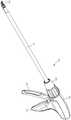
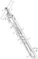
도 1은 본 발명에 따른 죠부재 가이드부를 갖는 클립 어플라이어의 사시도,
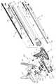
도 2는 본 발명에 따른 죠부재 가이드부를 갖는 클립 어플라이어의 분리 사시도,
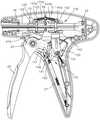
도 3은 본 발명에 따른 죠부재 가이드부를 갖는 클립 어플라이어클립 어플라이어의 단면도.
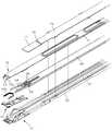
도 4는 도 2에 도시된 죠조작유닛을 발췌하여 도시한 분리 사시도.
도 5 및 도 6은 본 발명에 따른 죠조작유닛의 다른 실시예를 나타내 보인 사시도,
도 7는 도 2에 도시된 클립로딩유닛을 발췌하여 도시한 사시도.
도 8은 클립로딩유닛의 가이드본체부와 카트리지 유닛 및 클립로딩부재가 결합된 상태의 일부절제 사시도,
도 9은 도 2에 도시된 핸들하우징의 분리 사시도.
도 10은 도 2에 도시된 핸들 하우징의 이부절제 단면도,
도 11는 죠부재 가이드부를 갖는 클립 어플라이어의 작동상태를 내보인 측단면도,
도 12은 죠부재 가이드부를 갖는 클립 어플라이어의 죠에 의해 클립이 결찰되는 상태를 개략적으로 나타내 보인 사시도,
도 13은 죠부재 가이드부를 갖는 클립 어플라이어의 측단면도,
도 14은 죠부재 가이드부를 갖는 클립 어플라이어의 클립로딩유닛에 의해 클립이 로딩되는 상태를 나타내 보인 확대 단면도,
도 15 및 도 16는 클립 어플라이어의 클립결착안전유닛의 작동상태를 나타내 보인 도면,
도 17은 본 발명의 클립어플라이어의 결착확인완료유닛을 나타내 보인 단면도,
도 18, 도 19은 도 4에 도시된 죠조작유닛의 사용상태를 발췌하여 도시한 사시도.1 is a perspective view of a clip applier having a jaw member guide portion according to the present invention,
2 is an exploded perspective view of a clip applicator having a jaw member guide portion according to the present invention,
3 is a cross-sectional view of a clip applier clip applicator having a jaw member guide portion according to the present invention.
Fig. 4 is an exploded perspective view showing the jaw operating unit shown in Fig. 2; Fig.
5 and 6 are perspective views showing another embodiment of the jaw operating unit according to the present invention,
FIG. 7 is a perspective view illustrating the clip loading unit shown in FIG. 2; FIG.
8 is a partially cutaway perspective view showing a state in which the guide body portion of the clip loading unit, the cartridge unit and the clip loading member are engaged,
Figure 9 is an exploded perspective view of the handle housing shown in Figure 2;
Fig. 10 is a cross-sectional view of the handle housing shown in Fig. 2,
11 is a side sectional view showing the operating state of the clip applicator having the jaw member guide portion,
12 is a perspective view schematically showing a state in which the clip is ligated by the jaws of the clip applier having the jaw member guide portion,
13 is a side sectional view of a clip applicator having a jaw member guide portion,
14 is an enlarged sectional view showing a state in which the clip is loaded by the clip loading unit of the clip applicator having the jaw member guide portion,
15 and 16 are diagrams showing an operating state of the clip binding safety unit of clip applier,
17 is a sectional view showing the binding confirmation completion unit of the clip applicator of the present invention,
Figs. 18 and 19 are perspective views illustrating the use state of the jaw operating unit shown in Fig. 4; Fig.
본 발명에 따른 죠부재 가이드부를 갖는 클립 어플라이어는 개복하지 않고 수술 중에 혈관, 덕트, 션트 또는 바디 조직의 일부를 결찰하기 위한 것으로, 그 일 실시예를 도 1 내지 도 19에 나타내 보였다.A clip applier having a jaw member guide portion according to the present invention is for ligation of a blood vessel, a duct, a shunt, or a part of a body tissue during an operation without opening the lid. One embodiment thereof is shown in Figs.
도면를 참조하면, 본 발명에 따른 죠부재 가이드부를 갖는 클립 어플라이어(10)는 핸들하우징(20)과, 상기 핸들하우징(20)에 설치되며 소정의 길이와 중공부(22)를 가지는 관부재(21)를 구비한다. 그리고 상기 관부재(21)에 설치되는 것으로, 핸들 하우징(20)에 일측이 고정되며 상기 관부재(21)의 중공부(22)로 로드(41)와, 상기 로드(41)의 단부에 설치되어 개방 위치와 폐쇄 위치 사이에서 이동 가능하도록 대향되며 대응되는 면에 클립지지부가 각각 마련된 제1,2죠(42)(43)들로부터 연장되어 상기 제1,2죠가 열림방향으로 탄성력을 제공하는 탄성지지부(44)(45)를 가진 죠부재(46)와 상기 로드(41)에 슬라이딩 가능하게 설치되어 죠부재(46)의 제1,2 죠(42)(43)를 개폐하는 슬라이더(48)를 포함하는 죠조작유닛(40)을 구비한다.A
상기 죠조작유닛(40)의 하부측 관부재(21)의 중공부(22) 내에 설치되며 단부에 상기 제1,2죠(42)(43)의 측으로 클립(200)을 공급하기 위한 클립가이드부(51)가 마련된 가이드본체부(50)와, 상기 가이드본체부(50) 상에 설치되어 클립공급하기 위한 카트리지유닛(60)과, 상기 카트리지유닛(60)으로부터 공급되는 클립을 상기 클립가이드부(51)을 따라 이동시켜 제1,2죠(42)(43)의 클립지지부에 로딩하는 클립로딩부재(71)와, 상기 가이드본체부(50)와 결합되어 클립로딩부재의 이송을 가이드 하는 커버부재(75)를 구비한 클립로딩유닛(70)과,The
상기 핸들하우징(20)에 설치된 레버(26)의 후퇴 시 상기 슬라이더(48)를 전진시켜 제1,2죠(42)(43)를 닫히는 방향으로 이동시켜 클립을 결찰하고, 레버(26)의 전진 시 상기 클립로딩부재(71)를 전진시켜 클립을 상기 클립지지부(42a)(43a)에 공급하는 조작유닛(100)을 구비한다.The
상술한 바와 같이 구성된 본 발명에 따른 죠부재 가이드부를 갖는 클립 어플라이어(10)를 구성요소 별로 보다 상세하게 설명하면 다음과 같다.The
본 발명에 따른 클립 어플라이어(10)는 쓸개 절제술, 위창냄술, 막창자 꼬리 절제술 및 탈장 복구술 등의 복강경 및 내시경 외과 시술의 실행하는 과정에서 혈관, 덕트, 션트 또는 바디 조직의 일부를 클립(200)을 이용하여 결찰하기 위한 것이다. 상기 핸들하우징(20)은 두 개의 부재가 결합되어 이루어진 것으로, 하방으로 손잡이부(25)가 구비되고, 이 손잡이부(25)의 전면에 회동가능하게 설치되는 레버(26)구비한다. 그리고 관부재(21)는 핸들하우징(20)의 전면에 내부와 연통되도록 설치되는 캡(23)에 의해 지지되는 것으로, 복강경의 시술을 위한 충분한 길이와 중공부(22)를 가진다.(도 1참조) 상기 핸들하우징(20)은 상술한 실시예에 의해 한정되지 않고, 다양한 형상으로 디자인 될 수 있다.The clip applier 10 according to the present invention can be used to clip a portion of a vessel, duct, shunt or body tissue in the course of performing laparoscopic and endoscopic surgical procedures, such as gall bladder surgery, gastroenterectomy, ). ≪ / RTI > The
상기 죠조작유닛(40)은 도 2 내지 도 6에 도시된 바와 같이 제1,2죠(42)(43)의 클립지지부(42a)(43a)에 지지된 클립(200)을 이용하여 혈관, 덕트, 션트 또는 바디 조직의 일부를 클립(200)을 이용하여 결찰하기 위한 것으로, 관부재(21)의 중공부(22)에 위치되며 일측단부가 핸들하우징(20)에 설치되는 가이드레일부재(110)의 전단부에 지지되는 로드(41)와, 로드의 단부에 설치되는 죠부재(46)를 구비한다. 그리고 상기 조작유닛(100)에 의해 전후진되며 조부재가 끼워져 죠부재(46)의 제1,2죠(42)(43)를 상대 이동시키기 위한 슬라이더(48)를 구비한다. 2 to 6, the
상기 로드(41)에는 길이 방향으로 가이드홈(41a)이 형성되어 슬라이더(48)가 가이드 된다. 그리고 로드의 단부(41) 측에는 죠부재(46)를 지지하기 위한 복수개의 지지돌기(41b)들이 형성된다. 상기 로드(41)의 전단부는 죠부재(46)와 결합 시 죠부재(46)의 제1,2죠(42)(43)가 관부재(21)의 단부로 돌출될 수 있는 길이를 가진다.A
상기 죠부재(46)는 상기 지지돌기(41b)와 대응되는 위치에 이와 결합되는 복수개의 결합공(47a)이 형성된 기부(47)와, 상기 기부(47)로부터 점차 벌어지는 각도로 연장되는 탄성지지부(44)(45)들과 각 탄성지지부(44)(45)의 단부에 형성되는 제1,2죠(42)(43)를 구비한다. 상기 제 1,2죠(42)(43)는 단부가 관부재(21)의 중심으로부터 상방향으로 경사지도록 설치되어 클립(200)의 결찰이 원활하게 수행될 수 있도록 하며, 후술하는 클립로딩유닛에 의해 클립(200)이 원활하게 로딩될 수 있도록 함이 바람직하다. 그리고 상기 제1,2죠(42)(43)의 상호 대응되는 면에는 결착을 위한 클립(200)을 지지하기 위한 클립지지부(42a)(43a)가 형성된다.The
그리고 상기 조작유닛(100)에 의해 전후진 되는 슬라이더(48)의 단부측에는 상기 죠부재(46)와 결합되어 전진 시 상기 제1,2죠(42)(43)를 닫히는 방향으로 이동시켜 클립을 결착할 수 있도록 하고, 후퇴 시 죠부재(46)의 탄성지지부(44)(45)에 의해 열리도록 하는 죠조작부(48a)를 구비한다. 상기 죠조작부(48a)의 폐쇄된 단면적은 제1,2죠(42)(43)이 밀착되었을 때 근접된 탄성지지부(44)(45)의 단면적과 실질적으로 동일하게 형성되어 슬라이더(48)의 전,후진 시 상기 제1,2죠(42)(43)가 개폐될 수 있도록 함이 바람직하다. 그리고 상기 죠조작부(48a)로부터 연장되며, 죠부재(46)가 슬라이딩 될 수 있도록 찬넬 형상의 유도가이드홈(48b)이 형성되고, 로드(41)에 설치된 지지돌기(41b)와 대응되는 부위에 죠부재(46)와 지지돌기(41b)의 결합과 로드(21) 및 죠부재(46)에 대해 슬라이딩 가능하도록 길이 방향으로 장공(48c)이 형성된 슬라이드 본체부(48d)를 포함한다. 그리고 상기 죠조작부(48a)의 후단부에는 이로부터 상기 유도가이드홈(48b) 측으로 연장되어 죠부재(46)의 탄성지지부(44)(45)를 가이드하기 위한 보조가이드편(48e)을 구비한다. 구비한다.The first and
그리고 상기 로드(41)의 지지돌기(41b)와 대응되는 상기 슬라이더(48)의 일측에는 상기 로드(41)로부터 죠부재(46)가 분리되는 것을 방지하며, 죠부재가 슬라이더(48)를 벗어나지 않고, 직선운동을 유도하기 위한 가이드부(49)가 구비된다.The
상기 가이드부(49)는 슬라이더(48)의 일측으로부터 죠부재(46)의 두께방향으로 연장되는 가이드지지부(49a)와, 상기 가이드지지부(49a)로부터 슬라이더(48)와 나란한 방향으로 연장되며, 상기 죠부재(46)의 기부(47)와 접촉되는 가이드편(49b)을 구비한다. 상기 가이드편(49b)은 판상의 슬라이더본체부(48d)를 렌싱 가공하여 형성할 수 있다.The
상기 가이드부(49)는 상술한 실시예에 의해 한정되지 않고, 도 5에 도시된 바와 같이 상기 로드(41)의 지지돌기(41b)에 지지된 기부(47)과 대응되는 슬라이드본체부(48d)의 상하측에 이로부터 상호 대향되는 방향으로 연장되는 가이드돌기(49d)로 이루어질 수 있다.The
그리고 가이드부(49)의 또 다른 실시예로서는 도 6에 도시된 바와 같이 상기 로드(41)의 지지돌기(41b)에 지지된 기부(47)와 대응되는 슬라이더본체부(48d)의 일측부터 연장되어 상기 죠부재(46)의 외면과 밀착되는 판부재(49e)로 이루어질 수 있다.Another embodiment of the
상기 로드(41)은 후술하는 가이드본체부(50)와 결합되어 관부재(21)의 중공부에 위치되며, 슬라이더(48)가 이동하는 가이드홈(41a)을 구획하게 된다.The
상기 클립로딩유닛(70)은 도 2 내지 도 6에 도시된 바와 같이 상기 죠조작유닛(40)의 제 1,2죠(42)(43)의 클립지지부(42a)(43a)에 클립을 로딩하기 위한 것으로, 관부재(21)의 중공부(22)에 위치되며 단부에 클립가이드부(51)가 마련된 가이드본체부(50)를 구비한다. 상기 클립가이드부(51)에는 클립(200)을 클립지지부(42a)(43a)로 유도하기 위한 탄성가이드편(55)이 설치된다. 상기 가이드본체부(50)는 로드(41)와 결합된다. 그리고 상기 가이드본체부(50)에는 길이 방향으로 클립의 공급을 위한 카트리지 장착부(52)가 형성되고, 이 카트리지 장착부(52)에는 클립들이 로딩된 카트리지유닛(60)이 설치된다. 상기 카트리지 유닛(60)은 내부에는 상세하게 도시되어 있지 않으나 클립들이 길이 방향으로 적층되는 클립장착공간이 형성된 카트리지본체와, 상기 카트리지 본체에 설치되어 클립장착공간에 적층된 클립을 전면측으로 탄성스프링에 의해 탄성바이어스 시키는 푸셔가 설치된다. 그리고 카트리지 본체의 상부측 단부에는 상기 클립장착공간로부터 푸셔에 의해 인출되는 클립을 가압하기 위한 클립가압탄성편(64)이 설치되고, 이 클립가압탄성편(64)의 양측에는 유도가이드홈(66)가 형성된다. 상기 클립가압탄성편(64)에는 길이 방향으로 랜싱가공되어 이루어진 클립가압보조탄성편(65)이 구비된다.2 to 6, the
그리고 상기 가이드본체부(50)의 카트리지 장착부(52)에 장착된 카트리지 유닛(60)의 상면에는 상기 조작유닛(100)에 의해 상기 슬라이더(48)과 상대이동(상호 반대로 전,후진)하는 클립로딩부재(71)가 설치된다.The
상기 클립로딩부재(71)의 전단부측에는 상기 클립로딩부(72)가 설치되는데, 상기 클립로딩부(72)에는 상기 유도가이드홈(66)과 결합되어 클립(200)을 이동시키기 위한 이송돌기(73)가 형성된다. 상기 이송돌기(73)는 클립로딩부재(71)의 후퇴시 클립(200)에 간섭이 발생되지 않도록 후면(73a)이 경사지게 형성되어 있으며, 전면측은 수직상태를 이룬다. 클립로딩부재(71)의 후단부측은 후술하는 제 2핀과 결합될 수 있도록 제 2핀결합공(71a)이 형성되어 있으며, 이와 인접되는 측에는 상기 슬라이더(48)와 결합되는 제1핀이 관통하며 클립로딩부재(71)의 전,후진 시 제1핀과의 간섭이 발생되지 않도록 장공(71b)이 형성된다.The
그리고 상기 클립로딩부재(71)의 상부에는 가이드본체(50)의 양측가장자리와 양측이 결합되어 상기 클립로딩부재(71)의 전,후진 시 가이드 공간을 확보하기 위한 커버부재(75)가 설치된다. 상기 커버부재(75)의 단부에는 상기 클립로딩부재(71)의 전, 후진 시 상기 클립로딩부재(71)의 단부 즉, 클립로딩부(72)를 카트리지 측으로 탄압하기 위하여 하방으로 절곡된 절곡부(76)가 형성되고, 이 절곡부(76)으로부터 수평방향으로 연장되는 가압부(77)가 형성된다.A
상기 조작유닛(100)는 상기 슬라이더(48)와 클립로딩부재(71)를 상대이동시켜 죠부재(46)의 제 1,2죠(42)(43)의 클립지지부(42a)(43a)에 장착된 클립을 이용하여 신체를 결찰함과 아울러 결찰 후 빈 클립지지부에 클립로딩유닛(70)에 의해 클립을 로딩하기 위한 것으로 도 1 내지 3 및 도 9에 나타내 보였다.The
도면을 참조하면, 조작유닛(100)은 핸들하우징(20)와 캡(23)에 의해 지지된 관부재(21)와 대응되는 하우징의 내부에 설치되는 가이드레일부재(110)를 구비한다. 상기 가이드레일부재(110)는 길이 방향으로 분리된 두 개의 제1,2부재(111)(112)로 이루어지며 대응되는 내부에는 상기 슬라이더(48)와 클립로딩부재(71)가 전후방향으로의 이동 시 이를 가이드하기 위해 길이 방향으로 인입 형성된 제 1가이드부(101)가 형성된다. 또한 가이드레일부재(110)의 외주면에는 고정 및 구획을 위한 복수개의 둘레턱(113)이 형성되는데,이 둘레턱(113)의 외주면에는 핸들하우징(20)의 내부에 형성된 리브와 결합되는 결합홈(113a)이 형성된다.The
상기 가이드레일부재(110)의 전단측에는 핸들하우징(20)에 설치된 레버(26)를 당겨 반시계방향으로의 회전 시 상기 관부재(21)의 내부에 설치된 죠조작유닛(40)의 슬라이더(48)을 전진시키고 상기 레버(26)의 시계방향의 회전 시 슬라이더를 후퇴시키는 제1이송부(120)를 구비한다. 또한 상기 가이드레일부재(110)의 후단측에는 핸들하우징(20)에 설치된 레버(26)를 당겨 반시계방향으로의 회전 시 상기 관부재(21)의 내부에 설치된 클립로딩유닛(70)의 클립로딩부재(71)후퇴시키고, 상기 레버(26)의 시계방향의 회전 시 클립로딩부재(71)를 전진시키는 제 2이송부(140)를 구비한다.A
상기 제 1이송부(120)는 상기 가이드레일부재(110)에는 길이 방향으로 관통되며 소정길이를 가지는 제1가이드공(121)이 형성되고, 이 제1가이드공(121)에는 상기 관부재(21)의 내부에 설치되며 상기 제1가이드부재(101)에 의해 안내되는 죠죠작유닛(40)의 슬라이더(48)의 단부에 형성된 제1핀결합공(48c)과 결합되는 제 1핀(122)이 가이드레일부재(110)의 길이 방향으로 전,후진 가능하게 설치된다. 그리고 상기 가이드레일부재(110)에는 제1핀(122)의 상하부를 지지하며 가이드레일부재(110)를 따라 전, 후 방향으로 슬라이딩 되는 제1이송부재(125)가 설치된다. 상기 제 1이송부재(125)는 상하방향으로 분리되는 두 개의 부재가 결합되어 이루어지며 양측에는 이 제1이송부재(125)를 가이드레일부재(110)를 따라 전, 후진시키기 위한 제 1이송축(126)이 설치된다. 상기 제 1이송축(126)의 단부에는 후술하는 훅이 이탈되는 것을 방지하는 제1걸림턱(127)이 형성된다. 또한 상기 레버(26)의 상부측에는 상기 제1이송부재(125)의 양측에 설치되는 제1이송축(126)과 결합되는 제1훅부재(129)가 설치된다. 상기 제1훅부재(129)는 레버(26)와 일체로 형성되며, 레버(26)의 회전방향과 반대방향으로 회전될 수 있도록 레버(26)을 지지하는 제1힌지축(25)의 상부측에 위치된다. 상기 제1훅부재(129)는 제1이송축(126)과 결합되는 이를 전후진 시키는 과정에서 간섭이 발생되지 않도록 제1이송축결합부(130)의 상부가 개방된 구조를 가진다.The
상기 제 2이송부(140)는 상기 가이드레일부재(110)에 형성된 제1가이드공(121)과 인접되는 후방측의 가이드레일부재(110)에 길이 방향으로 관통되며 소정길이를 가지는 제2가이드공(141)이 형성되고, 이 제2가이드공(141)에는 상기 관부재(21)의 내부에 설치되며 상기 제1가이드부재(101)에 의해 안내되는 클립로딩부재(71)의 단부에 형성된 제2핀결합공(71a)과 결합되는 제 2핀(142)이 가이드레일부재(110)의 길이 방향으로 전,후진 가능하게 설치된다. 그리고 상기 가이드레일부재(110)에는 제2핀(142)의 상하부를 지지하며 가이드레일부재(110)를 따라 전, 후 방향으로 슬라이딩 되는 제2이송부재(145)가 설치된다. 상기 제 2이송부재(145)는 상하방향으로 분리되는 두 개의 부재가 결합되어 이루어지며 양측에는 이 제2이송부재(145)를 가이드레일부재(110)을 따라 전, 후진시키기 위한 제 2이송축(146)이 설치된다. 상기 제 2이송축(146)의 단부에는 후술하는 훅이 이탈되는 것을 방지하는 제2걸림턱(147)이 형성된다.The second conveying
또한 상기 레버(26)의 회전력에 의해 상기 제 2이송부재(145)를 전후진시키기 위하여 상기 핸들하우징(20)에 제2훅부재(150)가 제 2힌지축(151)에 의해 회전가능하게 설치되고, 상기 제 2훅부재(151)의 상부측에는 제2이송축(146)과 결합되어 이를 전,후진 시키는 위한 제2이송축결합부(153)가 구비된다. 이 제2이송축결합부(153)는 제 2이송부재(145)의 전, 후진 시 제2이송축(146)과의 간섭이 발생되지 않도록 상부가 개방된 U 형의 제2이송축결합홈(153a)이 형성된다. 상기 레버(26)의 회전력을 상기 제 2훅부재(150)로 전달하기 위하여 상기 레버(26)의 일측으로부터 연장되는 제1작동연장부(155)와 제 2훅부재(150)로부터 연장되는 제 2작동연장부(156)가 형성되고, 상기 제 2작동연장부(156)에는 제 2훅부재(150)의 회전을 위한 제1가이드장공(157)이 형성되고, 이 제1가이드장공(157)은 제1작동연장부(156)에 마련된 가이드축(158)이 결합되어 레버(26)가 반시계방향으로 회전 시 훅부재(150)이 시계방향으로 회전하게 된다. 이를 위하여 상기 제1가이드 장공(157)은 제1작동연장부(156)의 길이 방향으로 형성되며 중앙부가 하방으로 연장되는 곡선의 형상으로 형성함이 바람직하다.The
상기 제 1,2이송부재(125)(145)의 상면측에는 스프링걸림돌기(125a)(145a)가 각각 형성되어 핸들하우징(20)에 형성된 스프링지지축(28)과 연결스프링(125b)(145b)들에 의해 연결됨으로써 상호 근접되는 방향으로 탄성바이어스 된다.
한편, 상기 조작유닛(100)은 상기 레버(26)의 조작으로 클립의 결착이 완전히 이루어질 때 레버가 복귀될 수 있도록 하는 클립결착안전유닛(170)과 결착완료확인유닛(180)을 더 구비한다.The
상기 클립결착안전유닛(170)은 도 11 내지 도 17에 나타내 보인 바와 같이 제1힌지축에 회전가능하게 설치되며, 레버(26)에 지지되는 지지부(171)와, 상기 지지부(171)의 타측에 설치되며 원호상으로 제1치(172a)들이 형성되는 랙부(172)를 포함하는 안전조작부재(173)를 구비한다. 상기 제1힌지축과 안전조작부재(173)의 결합부위는 지지부(171)와 랙부(172)의 사이에 위치된다. 그리고 랙부(172)와 인접되는 핸들하우징(20)에 설치는 제2힌지축(151)에는 일측에 제2힌지축(151)축으로부터 편심된 위치에 형성되어 클립의 결착을 위한 레버(26)의 후퇴 시 결합되지 않은 상태로 이동하고 클립의 결착을 위한 레버(26)의 후퇴가 충분히 이루어지지 않은 상태에서의 전진 시 상기 랙부(172)의 제1치(172a)와 결합되어 레버(26)의 전진을 방지하는 제 2치(175)랙들을 구비한 레치부재(176)가 설치된다. 상기 레치부재(176)에 설치된 제2치(175)들을 랙부(172)측으로 탄성바이어스 시키기 위한 래치부재(176)를 랙부(172) 측으로 회전시키기 위한 탄성스프링(177)을 구비한다.11 to 17, the clip binding
상기 래치부재(176)에 형성된 제 2치(175)는 레버(26)을 지지하는 제 1힌지축(25)과 제 2힌지축(151)의 중심을 연결하는 중심축선 보다 상부에 위치되며, 상기 랙부(172)의 제 1치들은 제 1힌지축(25)을 중심으로 하는 원호상(제1힌지축과 이격된 랙부의 거리에 해당하는 반경으로 갖는 원호)에 배열된다.The
상기 결착완료확인유닛(180)은 도 15 내지도 17에 도시된 바와 같이 작동연장부(155)로부터 연장되는 탄성부(181)와, 탄성부(181)의 단부에 설치되는 확인검출돌기(182)와, 상기 핸들하우징(20)에 설치되어 상기 확인검출돌기(182)을 가이드되는 동안 탄성부(181)가 타압되도록 하며 레버의 조작으로 클립결찰의 완료시 타탄성부의 탄성력이 해지되도록 결착검출가이드부(183)와, 상기 결착검출가이드부(183)으로부터 이격되어 상기 확인검출돌기(182)가 결착검출가이드부(183)로부터 분리 시 접촉되어 타격음을 발생시키는 타격판부(184)를 구비한다.The binding completion confirmation unit 180 includes an
상술한 바와 같이 구성된 본 발명에 따른 죠부재 가이드부를 갖는 클립 어플라이어의 작용을 설명하면 다음과 같다.The operation of the clip applicator having the jaw member guide portion according to the present invention constructed as described above will be described as follows.
먼저 죠부재 가이드부를 갖는 클립 어플라이어를 이용하여 복강경 및 내시경 외과 시술의 실행하는 과정에서 조직의 일부를 클립(200)을 이용하여 결찰하기 위해서는 죠조작유닛(40)의 제1,2죠(42)(43)의 클립지지부(42a)(43a)에 클립이 로딩되어 있는 상태에서 복부 내의 관부재(21)를 삽입하여 이의 단부에 설치되는 제1,2죠(42a)(43a)의 사이에 조직의 결찰부위가 위치되도록 한다.First, in order to perform a laparoscopic and endoscopic surgical procedure using a clip applicator having a jaw member guide portion, the first and
이 상태에서 상기 레버(26)를 당긴다. 이와 같이 하면, 도 10 내지 도 13에 도시된 바와 같이 조작유닛(100)의 레버(26)가 회전되면서, 레버(26)과 일체로 형성된 제 1훅부재(129)가 반시계방향으로 회전하게 되고, 제1이송부재(125)를 가이드레일부재(110)를 따라 전진시킴과 아울러 레버(26)의 제1작동연장부(155)와 가이드축(158)에 의해 연결된 제 2작동연장부(156)가 회전하여 제2훅부재(150)이 시계방향으로 회전됨으로써 제 2이송부재(145)가 가이드레일부재(110)를 따라 후퇴 되도록 한다.In this state, the
이와 연계하여 상기 제1이송부재(125)에는 가이드레일부재(110)의 제1가이드공(121)에 지지된 제1핀(122)과 결합되고, 제 1핀(122)은 슬라이더(48)의 제1핀결합공(48c)과 결합되어 있으므로 슬라이더(48)가 전진하게 된다.The
전진하는 상기 슬라이더(48)는 도 16 및 도 19에 도시된 바와 같이 로드(41)에 지지된 죠부재(46)를 따라 슬라이더(48)의 단부에 설치된 죠조작부(48a)가 이동되면서 탄성지지부(44)(45)에 지지된 제1,2죠(42)(43)를 닫히는 방향으로 이동시킨다. 특히 제1,2죠(42)(43)의 외측은 외측으로 경사지게 돌출되어 있으므로 죠조작부(48a)의 이동 시 제1,2죠(42)(43)가 조여지게 된다. 따라서 제1,2죠(42)(43)의 클립지지부(42a)(43a)에 지지된 클립(200)을 조여 혈관 등과 같은 조직을 결찰하게 된다.16 and 19, the
상기 슬라이더(48)가 죠부재(46)를 따라 이동하는 과정에서, 상기 가이드부(49)의 가이드편(49b)은 로드(41)에 지지된 기부(47)를 따라 이동하게 되므로 기부(47)가 로드(41)로부터 분리되는 것을 방지할 수 있다. 또한 상기 죠부재(46)를 따라 슬라이더(48)의 이동 시 상기 가이드편(49b)이 상기 죠부재(46)의 표면을 따라 이동하게 되므로 유도가이드홈(48b)에 죠부재가 설치된 상태에서 전후진하는 슬라이더(48)의 유도가이드홈(48b)으로부터 죠부재의 이탈을 방지하고, 죠부재(46)을 따라 이동하는 슬라이더(48)의 직진성을 향상시킬 수 있다. 특히, 상기 슬라이더(48)의 죠조작부(48a)에는 슬라이더(48)의 길이 방향으로 보조가이드편(48e)이 설치되어 있으므로 죠부재(46)를 따라 이동하는 슬라이더의 직진성을 더욱 향상시킬 수 있다.The
이러한 과정에서 상기 제2훅부재(153)가 시계방향으로 회전함에 따라 상기 와 같이 제 2이송부재(145)가 후퇴하게 되고, 이에 지지된 제 2핀(142)과 제 2핀결합공(71a)에 의해 결합된 클립로딩부재(71)가 후방으로 후퇴하게 된다. 따라서 클립로딩부재(71)의 단부에 설치된 클립로딩부(72)에 형성된 로딩돌기(73)가 유도가이드홈(66)을 따라 후방으로 이동하게 되고, 카트리지유닛(60)의 푸셔에 의해 공급된 클립(200)의 후면에 접촉됨으로써 클립이 로딩을 위한 대기상태에 있게 된다. 이때에 상기 가이드본체(50)과 결합된 커버부재(75)의 단부에는 하방으로 절곡된 가압부(77)가 형성되어 있으므로 이 가압부(77)에 의해 클립로딩부(72)는 하방으로 탄성가압된다.In this process, as the
상기와 같이 클립(200)의 결착이 완료된 상태에서 상기 레버(26)을 후방으로의 이송력 즉, 파지력을 제거하게 되면, 제1탄성스프링(27)에 레버(26)가 복귀된다. 상기 레버(26)의 복귀로 인하여 레버(26)가 전면측으로 회전되면, 상기 제 1이송부재(125)는 제1훅부재(129)에 의해 후퇴하게 된다. 따라서 제1이송부재(125)와 제1핀(122)에 의해 결합된 슬라이더(48)가 후퇴하게 되고, 상기 죠부재(46)과 결합된 슬라이더(48)의 죠조작부(48a)가 분리되어 제 1,2죠(42)(43)가 이를 지지하는 탄성지지부(44)(45)에 의해 벌어지게 된다.The
이러한 과정에서 상기 제 2이송부재(145)는 제 2훅부재(150)에 의해 전진하게 되고, 이와 제 2핀(142)와 제2핀결합공(71a)에 의해 결합된 클립로딩부재(71)가 전진하게 되며, 이의 단부에 구비된 클립로딩부(72)가 전진하면서 클립(200)을 상기 제1,2죠(42)(43)의 클립지지부(42a)(43a)에 로딩하게 된다. 이러한 과정에서 상기 카트리지유닛(60)의 단부에 마련된 클립가압편(64)는 클립(200)을 하방으로 눌러 가압하게 되고, 탄성가이드부(51)에 마련된 탄성가이드편(52)은 제1,2죠(42)(43)의 클립지지(42a)(43a)에 삽입된 클립을 탄압하여 이로부터 이탈되는 것을 방지한다.The second conveying
한편, 본 발명의 죠부재 가이드부를 갖는 클립 어플라이어는 클립결착안전유닛(170)을 구비하고 있으므로 상기와 같이 클립(200)에 의한 조직의 결찰이 완전히 이루어지는 않은 상태, 이와 더블어 클립로딩유닛(70)에 의한 클립(200)의 공급대기 상태가 완전히 이루어지지 않은 상태에서 레버(26)가 전진하는 것을 방지할 수 있다.Meanwhile, since the clip applicator having the jaw member guiding portion of the present invention includes the clip binding
이를 더욱 상세하게 설명하면, 클립(40)을 결찰하기 위하여 레버(26)를 당기게 되면, 레버(26)과 같이 회전하는 안전조작부재(173)의 랙부(172)가 래치부재(176)의 제 2치(175)와 접촉되면서 이동하게 된다. 이러한 이동은 상기 래치부재(176)에 형성된 제 2치(175)가 레버(26)을 지지하는 제 1힌지축(25)과 제 2힌지축(151)의 중심을 연결하는 중심축선 보다 상부에 위치되어 있으므로 렉부(172)의 이동시 제1,2치의 결합이 이루어지지 않게 된다.More specifically, when the
그러나 이동되는 과정에서 레버(26)의 이송력을 제거하게 되면, 안전조작부재(173)가 시계방향으로 레버와 같이 회전하게 되고, 랙부(172)의 제1치는 래치부재(176)의 제 2치와 결합되어 안전조작부재(73)와 레버(26)의 회전이 고정된다.However, when the feeding force of the
따라서 클립(200)이 완전히 결착되지 않은 상태에서는 레버의 복귀가 이루어지지 않게 된다.Therefore, when the
상기 레버(26)의 충분히 당겨 클립의 결찰이 완전히 이루어지는 경우 도 13에 도시된 바와 같이 랙부(172)가 래칫부재(176)의 제 2치를 벗어나게 된다. 이 상태에서 레버(26)가 복귀되면 도 14에 도시된 바와 같이 안전조작부재(173)은 반시계방향으로 회전하고, 랙부(172)는 래치부재(176)의 제 2치(175)와 결합되지 않고 미끄럼이동하게 되어 레버(26)가 원상태로 복귀된다.When the
한편, 상기 같이 레버의 충분히 당기는 과정에서 도 17에 도시되 바와 같이 결착완료확인유닛(180)의 클립의 결착을 위하여 레버(26)를 당기게 되면, 상기 확인검출돌기(182)가 결착검출가이드부(183)을 따라 가이드되면서 탄성부(181)이 탄압되고, 클립의 결착이 완료되는 시점에서 상기 결착검출가이드부(183)로부터 확인검출돌기(182)가 분리되면서 타격판부(184)를 타격하게 됨으로써 타격음을 발생시키게 된다. 그리고 레버(26)가 전진 시에는 상기 확인검출돌기(182)가 결착검출가이드부(183)의 후면을 따라 하강하게 되는데, 이때에 탄성부는 벌어지는 방향으로 탄압된다.17, when the
이상에서 설명한 바와 같이 본 발명에 따른 죠부재 가이드부를 갖는 클립 어플라이어는 한번의 레버조작으로 클립의 결찰과 클립의 공급이 동시에 이루어질 수 있으므로 그 구조가 상대적으로 간단하다. 또한 클립의 결찰이 완전하게 이루어지지 않은 상태에서 죠가 벌어지는 것을 방지하여 결찰에 따른 신뢰성을 높일 수 있다.As described above, the clip applier having the jaw member guide portion according to the present invention is relatively simple in that the ligation of the clip and the supply of the clip can be performed simultaneously by a single lever operation. In addition, it is possible to prevent the jaws from being opened in a state in which the clip is not completely lined, thereby enhancing the reliability of the ligation.
본 발명은 도면에 도시된 실시예를 참고로 설명되었으나 이는 예시적인 것에 불과하며, 본 기술 분야의 통상의 지식을 가진 사람이라면 이로부터 다양한 변형 및 균등한 타 실시예가 가능하다는 점을 이해할 것이다. 따라서 본 발명의 진정한 기술적 보호 범위는 첨부된 등록 청구 범위의 기술적 사상에 의해 정해져야 할 것이다.While the present invention has been particularly shown and described with reference to exemplary embodiments thereof, it is evident that many alternatives, modifications and variations will be apparent to those skilled in the art. Accordingly, the true scope of the present invention should be determined by the technical idea of the appended claims.
Claims (5)
Translated fromKorean상기 로드에 슬라이딩 가능하게 설치되어 죠부재의 제1,2죠를 개폐하는 슬라이더와, 상기 슬라이더에 설치되어 죠부재의 기부가 로드로부터 이탈되는 것을 방지하며, 슬라이더가 죠부재의 따라 이동을 가이드 하는 가이드부를 구비하는 죠조작유닛과; 상기 죠조작유닛의 하부측 관부재 내에 설치되며 단부에 상기 제1,2죠의 측으로 클립을 가이드 하는 클립가이드부가 마련된 가이드본체부와, 상기 가이드본체부 상에 설치되어 클립을 공급하기 위한 카트리지유닛과, 상기 카트리지유닛으로부터 공급되는 클립을 상기 클립가이드부을 따라 이동시켜 제1,2죠의 클립지지부에 로딩하는 클립로딩부재와, 상기 가이드본체부와 결합되어 클립로딩부재의 이송을 가이드 하는 커버부재를 구비한 클립로딩유닛과;
상기 핸들하우징에 설치된 레버의 후퇴 시 상기 슬라이더를 전신시켜 제1,2죠를 닫히는 방향으로 이동시켜 클립을 결찰하고, 레버의 전시 시 상기 클립로딩부재를 전진시켜 클립을 상기 클립지지부에 공급하는 조작유닛을 구비하며,
상기 죠조작유닛의 슬라이더에 설치되는 가이드부는 슬라이더의 일측으로부터 죠부재의 두께방향으로 연장되는 가이드지지부와, 상기 가이드지지부로부터 슬라이더와 나란한 방향으로 연장되며, 상기 죠부재의 기부와 밀착되는 가이드편을 구비하며,
상기 슬라이더는 상기 죠부재를 감싸며 죠부재를 따라 슬라이딩 시 제 1,2죠를 밀착 및 분리를 위한 죠조작부와, 상기 죠조작부로부터 연장되며 죠부재가 슬라이딩 될 수 있도록 찬넬형상의 죠부재 가이드홈을 가지며 로드에 설치된 지지돌기와 대응되는 부위에 죠부재와 지지돌기의 결합과 로드 및 죠부재에 대해 슬라이딩 가능하도록 길이 방향으로 장공이 형성된 슬라이드 본체부를 포함하고,
상기 죠조작부의 후단부에는 이로부터 가이드홈 측으로 연장되어 죠부재의 탄성지지부를 가이드하기 위한 보조가이드편을 구비한 것을 특징으로 하는 죠부재 가이드부를 갖는 클립 어플라이어.A tubular member installed in the handle housing and having a predetermined length and diameter; A rod extending from the handle housing, a base provided on the rod, and first and second jaws provided on ends of the elastic supports extended from the base to extend from the end of the rod, A jaw member provided,
A slider provided slidably on the rod for opening and closing the first and second jaws of the jaw member; a slider provided on the slider to prevent the base of the jaw member from being separated from the rod and guiding the movement of the slider along the jaw member A jaw operating unit having a guide portion; A guide body provided in a lower tube member of the jaw operation unit and provided with a clip guide portion for guiding a clip to the first and second jaws at an end thereof; A clip loading member for moving the clip supplied from the cartridge unit along the clip guide unit and loading the clip on the clip support unit of the first and second jaws, a cover member for guiding the movement of the clip loading member, A clip loading unit having a clip;
When the lever installed on the handle housing retracts, the slider is telegraphed to move the first and second jaws in the closing direction to ligate the clip, and when the lever is displayed, the clip loading member is advanced to feed the clip to the clip supporting portion Unit,
A guiding portion provided on the slider of the jaw operating unit includes a guide supporting portion extending from one side of the slider in the thickness direction of the jaw member and a guide piece extending in a direction parallel to the slider from the guide supporting portion, Respectively,
The slider includes a jaw operating part for closing and separating the first and second jaws when the jaw member is slid along the jaw member and a jaw member guide groove extending from the jaw operating part and having a channel- And a slide main body portion having a long hole in the longitudinal direction so as to be able to slide relative to the rod and the jaw member,
And a guide member extending from the rear end of the jaw operating part to the guide groove side for guiding the elastic support part of the jaw member.
핸들하우징과 레버에 설치되어 클립을 결찰을 확인할 수 있는 결착완료확인유닛을 더 구비하며, 상기 결착완료확인유닛은 레버에 설치된 작동연장부로부터 연장되는 탄성부와, 탄성부의 단부에 설치되는 확인검출돌기와, 상기 핸들하우징에 설치되어 상기 확인검출돌기을 가이드되는 동안 탄성부가 타압되도록 하며 레버의 조작으로 클립결찰의 완료시 타탄성부의 탄성력이 해지되도록 결착검출가이드부와, 상기 결착검출가이드부로부터 이격되어 상기 확인검출돌기가 결착검출가이드부로부터 분리 시 접촉되어 타격음을 발생시키는 타격판부를 구비한 것을 특징으로 하는 죠부재 가이드부를 갖는 클립 어플라이어.
The method according to claim 1,
The binding confirmation unit includes an elastic portion extending from an operation extension portion provided on the lever, and a confirmation completion detection unit provided on an end of the elastic portion, And a coupling detection guide portion which is provided on the handle housing to allow the elastic portion to be pressed while guiding the confirmation detecting protrusion and to release elasticity of the tartar portion when the clip is ligatured by operation of the lever, And a striking plate portion for contacting the confirmation detecting protrusion when detached from the binding detection guide portion to generate a hitting sound.
Applications Claiming Priority (2)
| Application Number | Priority Date | Filing Date | Title |
|---|---|---|---|
| KR1020160169028 | 2016-12-12 | ||
| KR20160169028 | 2016-12-12 |
Publications (2)
| Publication Number | Publication Date |
|---|---|
| KR20180067385A KR20180067385A (en) | 2018-06-20 |
| KR101966939B1true KR101966939B1 (en) | 2019-04-08 |
Family
ID=59422302
Family Applications (3)
| Application Number | Title | Priority Date | Filing Date |
|---|---|---|---|
| KR1020170016980AActiveKR101762761B1 (en) | 2016-12-12 | 2017-02-07 | clip applier |
| KR1020170021509AActiveKR101930414B1 (en) | 2016-12-12 | 2017-02-17 | clip applier having a clip loading unit |
| KR1020170021508AActiveKR101966939B1 (en) | 2016-12-12 | 2017-02-17 | clip applier having jaw guide |
Family Applications Before (2)
| Application Number | Title | Priority Date | Filing Date |
|---|---|---|---|
| KR1020170016980AActiveKR101762761B1 (en) | 2016-12-12 | 2017-02-07 | clip applier |
| KR1020170021509AActiveKR101930414B1 (en) | 2016-12-12 | 2017-02-17 | clip applier having a clip loading unit |
Country Status (2)
| Country | Link |
|---|---|
| KR (3) | KR101762761B1 (en) |
| WO (1) | WO2018110784A1 (en) |
Families Citing this family (6)
| Publication number | Priority date | Publication date | Assignee | Title |
|---|---|---|---|---|
| WO2019031620A1 (en)* | 2017-08-08 | 2019-02-14 | 주식회사 엔도비전 | Hemostatic clip providing device |
| KR102056153B1 (en)* | 2017-11-14 | 2019-12-16 | 주식회사 엔도비전 | Bidirectional vertebral endoscopic device for surgery |
| KR102036055B1 (en)* | 2018-01-17 | 2019-10-24 | (주)엘에이치코리아 | An Applier for a Medical Clip |
| CN110432947B (en)* | 2019-08-09 | 2024-04-19 | 伟格尔(广州)医疗设备有限公司 | Continuous hair clip applier |
| KR102820373B1 (en)* | 2023-07-03 | 2025-06-12 | 국립강릉원주대학교산학협력단 | surgical clip applier |
| KR20250083736A (en)* | 2023-12-01 | 2025-06-10 | 제이더블유생명과학 주식회사 | Surgical clip applier |
Citations (2)
| Publication number | Priority date | Publication date | Assignee | Title |
|---|---|---|---|---|
| KR101288789B1 (en) | 2005-04-14 | 2013-07-29 | 에디컨 엔도-서저리 인코포레이티드 | Surgical clip applier ratchet mechanism |
| US20140324074A1 (en) | 2013-03-26 | 2014-10-30 | Lawrence Crainich | Surgical clip applicator |
Family Cites Families (6)
| Publication number | Priority date | Publication date | Assignee | Title |
|---|---|---|---|---|
| US5527320A (en)* | 1994-02-10 | 1996-06-18 | Pilling Weck Inc. | Surgical clip applying instrument |
| US5700271A (en)* | 1995-10-20 | 1997-12-23 | United States Surgical Corporation | Apparatus for applying surgical clips |
| KR20020081295A (en)* | 2000-02-04 | 2002-10-26 | 이매진 메디칼 테크놀로지즈 캘리포니아, 인코포레이티드. | Surgical clip applier |
| US6911033B2 (en)* | 2001-08-21 | 2005-06-28 | Microline Pentax Inc. | Medical clip applying device |
| US7297149B2 (en) | 2005-04-14 | 2007-11-20 | Ethicon Endo-Surgery, Inc. | Surgical clip applier methods |
| US7731724B2 (en) | 2005-04-14 | 2010-06-08 | Ethicon Endo-Surgery, Inc. | Surgical clip advancement and alignment mechanism |
- 2017
- 2017-02-07KRKR1020170016980Apatent/KR101762761B1/enactiveActive
- 2017-02-17KRKR1020170021509Apatent/KR101930414B1/enactiveActive
- 2017-02-17KRKR1020170021508Apatent/KR101966939B1/enactiveActive
- 2017-06-21WOPCT/KR2017/006545patent/WO2018110784A1/ennot_activeCeased
Patent Citations (2)
| Publication number | Priority date | Publication date | Assignee | Title |
|---|---|---|---|---|
| KR101288789B1 (en) | 2005-04-14 | 2013-07-29 | 에디컨 엔도-서저리 인코포레이티드 | Surgical clip applier ratchet mechanism |
| US20140324074A1 (en) | 2013-03-26 | 2014-10-30 | Lawrence Crainich | Surgical clip applicator |
Also Published As
| Publication number | Publication date |
|---|---|
| KR20180067386A (en) | 2018-06-20 |
| KR101930414B1 (en) | 2019-03-11 |
| KR20180067385A (en) | 2018-06-20 |
| KR101762761B1 (en) | 2017-07-28 |
| WO2018110784A1 (en) | 2018-06-21 |
Similar Documents
| Publication | Publication Date | Title |
|---|---|---|
| KR101966939B1 (en) | clip applier having jaw guide | |
| US11517322B2 (en) | Articulating clip applier | |
| US10758244B2 (en) | Endoscopic surgical clip applier | |
| EP3366237B1 (en) | Endoscopic surgical clip applier | |
| US10729437B2 (en) | Devices and methods for manually retracting a drive shaft, drive beam, and associated components of a surgical fastening device | |
| KR101296092B1 (en) | Clip advancer mechanism with alignment features | |
| KR101283901B1 (en) | Clip applier with migrational resistance features | |
| US5792150A (en) | Apparatus for applying surgical clips with improved jaw and closure mechanisms | |
| KR101283902B1 (en) | Clip applier configured to prevent clip fallout | |
| CN100571640C (en) | Force limiting mechanism for medical instruments | |
| CN100522080C (en) | Surgical clip advancement and alignment mechanism | |
| CA2102346C (en) | Rotatable articulating endoscopic fastening instrument | |
| EP2485659B9 (en) | Clip advancer with lockout mechanism | |
| JP5073274B2 (en) | Surgical clip and applier device and method of use | |
| JP5490420B2 (en) | Surgical stapling instrument with improved firing trigger arrangement | |
| US8961542B2 (en) | Articulating clip applier cartridge | |
| RU2597771C2 (en) | Improved clip advancer | |
| CN110856662A (en) | Surgical clip applier and ligating clip | |
| BRPI0601903B1 (en) | SURGICAL CLAMP APPLICATOR AND CABLE ASSEMBLY | |
| MXPA06004249A (en) | Surgical clip applier methods | |
| MXPA06004250A (en) | Force limiting mechanism for medical instrument | |
| MXPA06004251A (en) | Surgical clip advancement mechanism | |
| MXPA06004252A (en) | Surgical clip applier ratchet mechanism | |
| HK1100161B (en) | Clip advancer mechanism with alignment features |
Legal Events
| Date | Code | Title | Description |
|---|---|---|---|
| A201 | Request for examination | ||
| PA0109 | Patent application | Patent event code:PA01091R01D Comment text:Patent Application Patent event date:20170217 | |
| PA0201 | Request for examination | ||
| E902 | Notification of reason for refusal | ||
| PE0902 | Notice of grounds for rejection | Comment text:Notification of reason for refusal Patent event date:20180521 Patent event code:PE09021S01D | |
| PG1501 | Laying open of application | ||
| E902 | Notification of reason for refusal | ||
| PE0902 | Notice of grounds for rejection | Comment text:Notification of reason for refusal Patent event date:20181129 Patent event code:PE09021S01D | |
| E701 | Decision to grant or registration of patent right | ||
| PE0701 | Decision of registration | Patent event code:PE07011S01D Comment text:Decision to Grant Registration Patent event date:20190329 | |
| GRNT | Written decision to grant | ||
| PR0701 | Registration of establishment | Comment text:Registration of Establishment Patent event date:20190402 Patent event code:PR07011E01D | |
| PR1002 | Payment of registration fee | Payment date:20190402 End annual number:3 Start annual number:1 | |
| PG1601 | Publication of registration | ||
| PR1001 | Payment of annual fee | Payment date:20220325 Start annual number:4 End annual number:4 | |
| PR1001 | Payment of annual fee | Payment date:20240307 Start annual number:6 End annual number:6 |