KR101965937B1 - Fault Signal Recovery Method and Apparatus - Google Patents
Fault Signal Recovery Method and ApparatusDownload PDFInfo
- Publication number
- KR101965937B1 KR101965937B1KR1020160153362AKR20160153362AKR101965937B1KR 101965937 B1KR101965937 B1KR 101965937B1KR 1020160153362 AKR1020160153362 AKR 1020160153362AKR 20160153362 AKR20160153362 AKR 20160153362AKR 101965937 B1KR101965937 B1KR 101965937B1
- Authority
- KR
- South Korea
- Prior art keywords
- signal
- reconstruction
- tags
- restoration
- unit
- Prior art date
- Legal status (The legal status is an assumption and is not a legal conclusion. Google has not performed a legal analysis and makes no representation as to the accuracy of the status listed.)
- Active
Links
Images


Classifications
- G—PHYSICS
- G05—CONTROLLING; REGULATING
- G05B—CONTROL OR REGULATING SYSTEMS IN GENERAL; FUNCTIONAL ELEMENTS OF SUCH SYSTEMS; MONITORING OR TESTING ARRANGEMENTS FOR SUCH SYSTEMS OR ELEMENTS
- G05B13/00—Adaptive control systems, i.e. systems automatically adjusting themselves to have a performance which is optimum according to some preassigned criterion
- G05B13/02—Adaptive control systems, i.e. systems automatically adjusting themselves to have a performance which is optimum according to some preassigned criterion electric
- G05B13/04—Adaptive control systems, i.e. systems automatically adjusting themselves to have a performance which is optimum according to some preassigned criterion electric involving the use of models or simulators
- G—PHYSICS
- G05—CONTROLLING; REGULATING
- G05B—CONTROL OR REGULATING SYSTEMS IN GENERAL; FUNCTIONAL ELEMENTS OF SUCH SYSTEMS; MONITORING OR TESTING ARRANGEMENTS FOR SUCH SYSTEMS OR ELEMENTS
- G05B23/00—Testing or monitoring of control systems or parts thereof
- G05B23/02—Electric testing or monitoring
- G05B23/0205—Electric testing or monitoring by means of a monitoring system capable of detecting and responding to faults
- G05B23/0259—Electric testing or monitoring by means of a monitoring system capable of detecting and responding to faults characterized by the response to fault detection
- G05B23/0286—Modifications to the monitored process, e.g. stopping operation or adapting control
- G05B23/0289—Reconfiguration to prevent failure, e.g. usually as a reaction to incipient failure detection
- G—PHYSICS
- G05—CONTROLLING; REGULATING
- G05B—CONTROL OR REGULATING SYSTEMS IN GENERAL; FUNCTIONAL ELEMENTS OF SUCH SYSTEMS; MONITORING OR TESTING ARRANGEMENTS FOR SUCH SYSTEMS OR ELEMENTS
- G05B13/00—Adaptive control systems, i.e. systems automatically adjusting themselves to have a performance which is optimum according to some preassigned criterion
- G05B13/02—Adaptive control systems, i.e. systems automatically adjusting themselves to have a performance which is optimum according to some preassigned criterion electric
- G05B13/0265—Adaptive control systems, i.e. systems automatically adjusting themselves to have a performance which is optimum according to some preassigned criterion electric the criterion being a learning criterion
- G—PHYSICS
- G05—CONTROLLING; REGULATING
- G05B—CONTROL OR REGULATING SYSTEMS IN GENERAL; FUNCTIONAL ELEMENTS OF SUCH SYSTEMS; MONITORING OR TESTING ARRANGEMENTS FOR SUCH SYSTEMS OR ELEMENTS
- G05B23/00—Testing or monitoring of control systems or parts thereof
- G05B23/02—Electric testing or monitoring
- G05B23/0205—Electric testing or monitoring by means of a monitoring system capable of detecting and responding to faults
- G05B23/0218—Electric testing or monitoring by means of a monitoring system capable of detecting and responding to faults characterised by the fault detection method dealing with either existing or incipient faults
- G05B23/0221—Preprocessing measurements, e.g. data collection rate adjustment; Standardization of measurements; Time series or signal analysis, e.g. frequency analysis or wavelets; Trustworthiness of measurements; Indexes therefor; Measurements using easily measured parameters to estimate parameters difficult to measure; Virtual sensor creation; De-noising; Sensor fusion; Unconventional preprocessing inherently present in specific fault detection methods like PCA-based methods
- G—PHYSICS
- G05—CONTROLLING; REGULATING
- G05B—CONTROL OR REGULATING SYSTEMS IN GENERAL; FUNCTIONAL ELEMENTS OF SUCH SYSTEMS; MONITORING OR TESTING ARRANGEMENTS FOR SUCH SYSTEMS OR ELEMENTS
- G05B23/00—Testing or monitoring of control systems or parts thereof
- G05B23/02—Electric testing or monitoring
- G05B23/0205—Electric testing or monitoring by means of a monitoring system capable of detecting and responding to faults
- G05B23/0259—Electric testing or monitoring by means of a monitoring system capable of detecting and responding to faults characterized by the response to fault detection
- G05B23/0286—Modifications to the monitored process, e.g. stopping operation or adapting control
- G—PHYSICS
- G06—COMPUTING OR CALCULATING; COUNTING
- G06F—ELECTRIC DIGITAL DATA PROCESSING
- G06F30/00—Computer-aided design [CAD]
- G06F30/10—Geometric CAD
- G06F30/17—Mechanical parametric or variational design
- G—PHYSICS
- G06—COMPUTING OR CALCULATING; COUNTING
- G06N—COMPUTING ARRANGEMENTS BASED ON SPECIFIC COMPUTATIONAL MODELS
- G06N20/00—Machine learning
- G—PHYSICS
- G06—COMPUTING OR CALCULATING; COUNTING
- G06N—COMPUTING ARRANGEMENTS BASED ON SPECIFIC COMPUTATIONAL MODELS
- G06N20/00—Machine learning
- G06N20/20—Ensemble learning
Landscapes
- Engineering & Computer Science (AREA)
- Physics & Mathematics (AREA)
- General Physics & Mathematics (AREA)
- Automation & Control Theory (AREA)
- Software Systems (AREA)
- Theoretical Computer Science (AREA)
- Artificial Intelligence (AREA)
- Evolutionary Computation (AREA)
- Computer Vision & Pattern Recognition (AREA)
- Medical Informatics (AREA)
- General Engineering & Computer Science (AREA)
- Geometry (AREA)
- Computing Systems (AREA)
- Data Mining & Analysis (AREA)
- Mathematical Physics (AREA)
- Health & Medical Sciences (AREA)
- Chemical Kinetics & Catalysis (AREA)
- Chemical & Material Sciences (AREA)
- Computational Mathematics (AREA)
- Computer Hardware Design (AREA)
- Pure & Applied Mathematics (AREA)
- Mathematical Optimization (AREA)
- Mathematical Analysis (AREA)
- Testing And Monitoring For Control Systems (AREA)
Abstract
Translated fromKoreanDescription
Translated fromKorean본 발명은 플랜트를 측정한 신호를 수집하고, 측정한 신호 중에 있는 이상 신호(Fault Signal)를 복원하기 위한 장치 및 방법에 관한 것으로, 더욱 자세하게는 이상 신호를 기계 학습 방법을 이용하여 정상 신호로 복원하기 위한 이상 신호 복원 장치 및 방법에 관한 것이다.The present invention relates to an apparatus and method for collecting a signal measuring a plant and recovering a fault signal in the measured signal. More specifically, the fault signal is restored to a normal signal using a machine learning method. The present invention relates to an abnormal signal recovery apparatus and method.
일반적으로 발전 또는 화학 등의 대형 플랜트(plant)들은 다양한 종류의 수백 개의 기계 및 전기 설비들이 복잡하게 연결되어 운전되고 있다. 이런 플랜트들은 신뢰성을 확보하여 안정적으로 전력을 공급하기 위해, 사고의 발단이 되는 이상 징후를 상시로 감시해야 한다. 이에, 플랜트를 구성하는 주요 구성 부품의 파손 여부를 실시간으로 감지하고 부품에 이상 징후가 발견되는 경우 운전자에게 알람을 발생시키는 감시장치가 이용되고 있다.In general, large plants, such as power generation or chemistry, are operated with complex connection of hundreds of various kinds of mechanical and electrical facilities. In order to ensure reliability and supply electricity reliably, these plants must be constantly monitored for signs of anomalies. Accordingly, a monitoring device that detects in real time whether or not the main components of the plant are damaged and generates an alarm to the driver when abnormal signs are found in the parts is used.
즉, 플랜트의 고장은 플랜트에 피해를 끼쳐 원하지 않는 성능을 보이게 되거나, 이에 더 나아가 플랜트가 파괴되는 경우, 사람이 다치거나 죽을 수 있으며, 환경 문제를 야기할 수도 있다. 따라서 조기에 고장을 감지할 수 있는 조기 경보 시스템이 반드시 필요한다.In other words, a plant failure can cause damage to the plant and result in undesired performance, or even worse, if the plant is destroyed, injuries or death, and can cause environmental problems. Therefore, there is a need for an early warning system that can detect failures early.
고장 또는 고장 가능성을 조기에 알려주는 조기 경보 시스템은 플랜트에서 실시간 관측 신호를 받아 저장하고, 이를 바탕으로 이상이 있는 신호를 분별하여 미리 알려주어야 한다. 그래서, 이러한 고장 감지 시스템에서 가장 중요한 부분은 조기에 고장을 예측할 수 있는 고장 예측 모델일 수 있다. 고장 예측 모델은 플랜트의 정상 상태를 정확히 예측하고, 정상 상태와 상이한 관측 신호가 들어오는 경우 고장이 났다고 예측할 수 있다.Early warning systems that provide early warning of failures or possible failures must receive and store real-time observation signals from the plant. Thus, the most important part of such a failure detection system may be a failure prediction model that can predict failure early. The failure prediction model accurately predicts the steady state of the plant and can predict that a failure has occurred when an observation signal different from the steady state is received.
고장 예측 모델이 가능한 한 정확하게 동작하기 위해서는 질 좋은 학습데이터가 필요하다. 즉, 질 좋은 학습데이터를 이용하여 정상상태에 대해 학습을 수행함으로써 고장 예측 모델의 정확성을 높일 수 있다. 따라서 정확한 고장 예측 모델을 위해서는 질 좋은 학습 데이터를 확보하는 것이 최우선 과제라 할 수 있다. 그런데 관측된 신호 중 대부분은 학습 데이터로써 매우 적합한데도 불구하고, 플랜트의 실질적인 고장뿐만 아니라 센서 고장이나 네트워크 문제 등으로 인하여 일부 센서에서 이상 신호가 들어오는 경우가 있다. 일반적으로 이러한 이런 이상 신호가 포함되어 있는 데이터를 학습 데이터로 사용할 수 없다. 하지만, 이러한 일부의 이상 신호 때문에 다른 질 좋은 데이터들을 버리기가 아까운 경우가 존재하며, 이러한 경우에 해당 이상 신호를 원래의 정상 신호로 복원할 수 있다면 전체 데이터를 학습 데이터로 사용할 수 있다.In order for the failure prediction model to work as accurately as possible, quality training data is required. That is, the accuracy of the failure prediction model can be improved by learning the steady state using high quality learning data. Therefore, for the accurate failure prediction model, securing high quality training data is the top priority. Although most of the observed signals are well suited as learning data, there are cases in which an abnormal signal comes from some sensors due to sensor failure or network problem as well as actual failure of the plant. In general, data containing these abnormal signals cannot be used as training data. However, there are cases where it is difficult to discard other quality data because of some of the abnormal signals. In this case, if the abnormal signals can be restored to the original normal signals, the entire data can be used as the training data.
이러한 이상 신호 복원 기술은 조기 경보 시스템이라면 당연히 갖추어야 하는 기술로써 인식되고 있다. 그리고 이상 신호 복원 기술에 의해 복원된 신호는 고장 예측 모델을 구축하기 위한 학습 데이터로 이용될 수 있기 때문에 정확한 고장 예측 모델을 만들기 위해서는 아주 정확한 복원 성능이 필요하게 된다. 하지만, 아직까지 이상 신호 복원 기술의 정확도는 많이 떨어지는 편으로 정확도를 높이기 위한 기술이 필요한 상황이다.This abnormal signal recovery technology is recognized as a technology that must be equipped with an early warning system. In addition, since the signal restored by the abnormal signal recovery technique can be used as training data for constructing a failure prediction model, a very accurate recovery performance is required to produce an accurate failure prediction model. However, the accuracy of the anomaly signal recovery technique is still poor, and a technique for increasing the accuracy is needed.
본 발명의 목적은, 우수한 복원 성능과, 어떤 대상에서도 적용할 수 있는 범용성을 갖추면서도, 쉽게 개발하고 유지보수가 가능하도록 기계 학습 알고리즘을 기반으로 한 이상 신호 복원 장치 및 방법을 제공함에 있다.SUMMARY OF THE INVENTION An object of the present invention is to provide an apparatus and method for recovering an abnormal signal based on a machine learning algorithm so as to be easily developed and maintained while having excellent restoration performance and generality applicable to any object.
전술한 목적을 해결하기 위한, 이상 신호를 정상 신호로 복원하기 위한 이상 신호 복원 장치는 복수 개의 태그 중 일부 태그에 대하여 이상 신호를 포함하고 있는 상기 복수 개의 태그에 대한 신호집합 U에서 상기 일부 태그의 이상 신호를 삭제 처리한 신호집합 U*를 생성하는 데이터처리부, 상기 복수 개의 태그에 대하여 모두 정상 신호를 포함하는 신호집합 X로부터 추출할 있는 신호 특징 정보 F 및 이상 신호 복원을 위해 사용할 수 있는 복수 개의 복원 모델에 대한 정보 P를 생성하는 모델링부, 및 상기 신호집합 U*, 상기 신호집합 X, 상기 특징 정보 F, 및 상기 복수 개의 복원모델에 대한 정보 P를 바탕으로 상기 일부 태그에 대한 정상 신호를 추정하여 복원하는 복원부를 포함할 수 있다. 이에 더하여 상기 데이터처리부는 상기 신호집합 X를 처리하여 상기 일부 태그에 대한 신호만으로 구성된 신호집합 Xs 및 상기 일부 태그를 제외한 나머지 태그에 대한 신호만으로 구성된 신호집합 X*를 더 생성하도록 구성될 수 있다.In order to solve the above object, the abnormal signal restoration apparatus for restoring the abnormal signal to the normal signal may include the partial tag in the signal set U for the plurality of tags including the abnormal signal for some of the plurality of tags. A data processing unit for generating a signal set U * from which an abnormal signal is deleted, signal characteristic information F which can be extracted from the signal set X including all normal signals, and a plurality of signals that can be used for restoring the abnormal signal; A modeling unit generating information P for a reconstruction model, and a normal signal for the some tags based on the signal set U *, the signal set X, the feature information F, and information P about the plurality of reconstruction models. It may include a recovery unit for estimating and restoring. In addition, the data processor may be configured to process the signal set X to further generate a signal set Xs including only signals for the some tags and a signal set X * including only signals for the remaining tags except for the some tags.
여기서 상기 모델링부는, 상기 데이터처리부로부터 입력 받은 신호집합 X*로부터 추출할 수 있는 특징을 포함하는 특징 정보 F를 추출하는 제1 특징추출부 및 상기 특징 정보 F 및 상기 데이터처리부로부터 입력 받은 신호집합 X* 및 Xs를 바탕으로 이상 신호 복원을 위해 사용할 수 있는 복수 개의 복원 모델에 대한 정보 P를 생성하는 모델생성부를 포함할 수 있고, 상기 복원부는, 상기 데이터처리부로부터 입력 받은 신호집합 U*로부터 추출할 수 있는 특징을 포함하는 특징 정보 F*를 추출하는 제2 특징추출부, 상기 모델링부로부터 입력 받은 상기 특징 정보 F 및 복수 개의 복원 모델 정보 P 및 상기 제2 특징추출부로부터 받은 상기 특징 정보 F*를 바탕으로 상기 복수 개의 복원 모델 중에서 이상 신호 복원에 사용할 복원 모델들을 선택하는 복원모델 선택부, 상기 복원모델선택부에서 선택한 복원 모델들을 이용하고 k-NN(k-Nearest Neighbor) 방식으로 상기 제1 태그그룹에 대한 제1 복원 신호 값을 생성하는 k-NN 기반 복원부, 상기 복원모델선택부에서 선택한 복원 모델들을 이용하고 MLRM(Multiple Linear Regression Model) 방식으로 상기 제1 태그그룹에 대한 제 2 복원 신호 값을 생성하는 MLRM 기반 복원부, 및 상기 제 1 복원 신호 값 및 제 2 복원 신호 값을 바탕으로 앙상블 학습을 이용하여 상기 제1 태그그룹에 대한 최종 복원 신호 값을 생성하는 앙상블 학습부를 포함할 수 있다.The modeling unit may include a first feature extracting unit for extracting feature information F including a feature that may be extracted from the signal set X * received from the data processing unit, and the feature set F and the signal set X received from the data processing unit. And a model generation unit for generating information P about a plurality of reconstruction models that can be used for reconstructing an abnormal signal based on Xs, wherein the reconstruction unit is extracted from a signal set U * received from the data processing unit. A second feature extracting unit for extracting feature information F * including a feature, a feature information F received from the modeling unit, a plurality of reconstruction model information P, and the feature information F * received from the second feature extracting unit; Reconstruction model selection for selecting reconstruction models to be used for abnormal signal recovery from the plurality of reconstruction models based on And a k-NN based reconstruction unit for generating a first reconstruction signal value for the first tag group using a reconstruction model selected by the reconstruction model selecting unit and performing a k-Nearest neighbor (k-NN) method. An MLRM based reconstruction unit using the reconstruction models selected by the selection unit and generating a second reconstruction signal value for the first tag group by a multiple linear regression model (MLRM) method, and the first reconstruction signal value and the second reconstruction signal An ensemble learner for generating a final reconstruction signal value for the first tag group using ensemble learning based on a value may be included.
그리고 상기 제1 특징추출부와 상기 제2 특징추출부는 동일한 기준 및 로직을 사용하여 특징을 추출할 수 있으며, 상기 k-NN 기반 복원부는 상기 복원모델선택부에서 선택한 복원 모델들의 결과와 상기 데이터처리부로부터 입력 받은 신호집합 Xs 간의 유사성을 나타내는 유사도를 계산하는 유사도추정모듈, 상기 k-NN 방식의 파라미터로 사용되는 k를 최적화하는 최적화모듈, 각 복원 모델별 가중치를 계산하는 가중치 모듈, 및 상기 가중치와 상기 복원 모델들의 결과를 바탕으로 복원값을 계산하는 복원모듈을 포함할 수 있고, 상기 MLRM 기반 복원부는 상기 복원모델선택부에서 선택한 복원 모델들의 추정 결과에 각 복원 모델별 가중치를 곱하고 더하여 상기 제1 태그그룹에 대한 제 2 복원 신호 값을 생성할 수 있다.The first feature extractor and the second feature extractor may extract a feature using the same criteria and logic, and the k-NN-based reconstruction unit may include a result of the reconstruction models selected by the reconstruction model selection unit and the data processor. A similarity estimation module for calculating a similarity indicating the similarity between the signal sets Xs received from a signal, an optimization module for optimizing k used as a parameter of the k-NN method, a weighting module for calculating a weight for each reconstruction model, and the weight and The reconstruction module may be configured to calculate a reconstruction value based on a result of the reconstruction models, wherein the MLRM-based reconstruction unit multiplies and adds the estimated results of reconstruction models selected by the reconstruction model selection unit to each weighted weight of each reconstruction model. The second reconstruction signal value for the tag group may be generated.
전술한 목적을 해결하기 위한, 이상 신호를 정상 신호로 복원하기 위한 이상 신호 복원 장치에서의 이상 신호 복원 방법은 복수 개의 태그 중 일부 태그에 대하여 이상 신호를 포함하고 있는 상기 복수 개의 태그에 대한 신호집합 U에서 상기 일부 태그의 이상 신호를 삭제 처리한 신호집합 U*를 생성하는 데이터처리 단계, 상기 복수 개의 태그에 대하여 모두 정상 신호를 포함하는 신호집합 X로부터 추출할 있는 신호 특징 정보 F 및 이상 신호 복원을 위해 사용할 수 있는 복수 개의 복원 모델에 대한 정보 P를 생성하는 복원모델 생성 단계, 및 상기 신호집합 U*, 상기 신호집합 X, 상기 특징 정보 F, 및 상기 복수 개의 복원모델에 대한 정보 P를 바탕으로 상기 일부 태그에 대한 정상 신호를 추정하여 복원하는 복원 단계를 포함할 수 있다. 이에 더하여 상기 데이터처리 단계는 상기 신호집합 X를 처리하여 상기 일부 태그에 대한 신호만으로 구성된 신호집합 Xs 및 상기 일부 태그를 제외한 나머지 태그에 대한 신호만으로 구성된 신호집합 X*를 생성하는 단계를 더 포함할 수 있다.In order to solve the above object, the abnormal signal restoration method in the abnormal signal restoration apparatus for restoring the abnormal signal to the normal signal includes a signal set for the plurality of tags including the abnormal signal for some of the plurality of tags. A data processing step of generating a signal set U * from which the abnormal signals of the some tags are deleted in U, the signal characteristic information F which can be extracted from the signal set X including all normal signals, and the abnormal signal restoration A reconstruction model generating step of generating information P about a plurality of reconstruction models usable for the step, and based on the signal set U *, the signal set X, the feature information F, and the information P on the plurality of reconstruction models The method may include a restoration step of estimating and restoring a normal signal for the some tags. In addition, the data processing step may further include the step of processing the signal set X to generate a signal set Xs consisting only of signals for the some tags and a signal set X * consisting only of signals for the remaining tags except for the some tags. Can be.
여기서, 상기 신호집합 X*로부터 추출할 수 있는 신호 특징 정보 F를 추출하는 제1 특징 추출 단계 및 상기 특징 정보 F 및 상기 신호집합 X* 및 Xs를 바탕으로 이상 신호 복원을 위해 사용할 수 있는 복수 개의 복원 모델에 대한 정보 P를 생성하는 복원 모델 생성 단계를 포함할 수 있고, 상기 복원 단계는 상기 신호집합 U*로부터 추출할 수 있는 신호 특징 정보 F*를 추출하는 제 2 특징추출 단계, 상기 신호 특징 정보 F 및 F*를 비교한 결과를 바탕으로 상기 복수 개의 복원 모델에 대한 정보 P로부터 이상 신호 복원에 사용할 복원 모델을 선택하는 복원모델 선택 단계, 상기 복원모델선택 단계에서 선택된 복원 모델들 중 적어도 하나를 이용하고 k-NN(k-Nearest Neighbor) 방식을 기반으로 상기 일부 태그에 대한 제1 복원값을 생성하는 k-NN 방식 기반 복원 단계, 상기 복원모델선택 단계에서 선택된 복원 모델들 중 적어도 하나를 이용하고 MLRM(Multiple Linear Regression Model) 방식을 기반으로 상기 일부 태그에 대한 제2 복원값을 생성하는 MLRM 방식 기반 복원 단계, 및 상기 제1 복원값 및 제2 복원값을 바탕으로 앙상블 학습을 이용하여 상기 일부 태그에 대한 복원값을 생성하는 단계를 포함할 수 있고, 상기 제1 특징추출 단계 및 상기 제 2 특징추출 단계는 동일한 기준 및 로직을 사용하여 특징을 추출할 수 있다.Here, a first feature extraction step of extracting signal feature information F that can be extracted from the signal set X * and a plurality of features that can be used to recover an abnormal signal based on the feature information F and the signal sets X * and Xs And a second feature extraction step of extracting signal feature information F * that can be extracted from the signal set U *, and the signal feature. A reconstruction model selection step of selecting a reconstruction model to be used for abnormal signal reconstruction from the information P for the plurality of reconstruction models based on a result of comparing the information F and F *, and at least one of reconstruction models selected in the reconstruction model selection step K-NN based restoration step of generating a first restoration value for the some tags based on the k-N (k-Nearest Neighbor) scheme, and An MLRM based restoration step of using at least one of the restoration models selected in the restoration model selection step and generating a second restoration value for the some tags based on a multiple linear regression model (MLRM) scheme; and the first restoration value And generating reconstruction values for the some tags using ensemble learning based on a second reconstruction value, wherein the first feature extraction step and the second feature extraction step use the same criteria and logic. Feature can be extracted.
그리고 상기 k-NN 방식 기반 복원 단계는 상기 복원모델선택 단계에서 선택한 복원 모델들의 결과와 상기 신호집합 Xs 간의 유사성을 나타내는 유사도를 계산하는 유사도추정 단계, 상기 k-NN 방식의 파라미터로 사용되는 k를 최적화하는 최적화 단계, 각 복원 모델별 가중치를 계산하는 가중치 계산 단계, 및 상기 가중치와 상기 복원 모델들의 결과를 바탕으로 복원값을 계산하는 복원값 계산 단계를 포함할 수 있고, 상기 MLRM 기반 복원 단계는 상기 복원모델선택 단계에서 선택한 복원 모델들의 추정 결과에 각 복원 모델별 가중치를 곱하고 더하여 이상 신호에 대한 제 2 복원 신호 값을 생성할 수 있다.The k-NN method based reconstruction step may include a similarity estimation step of calculating a similarity representing the similarity between the result of the reconstruction models selected in the reconstruction model selection step and the signal set Xs, and k used as a parameter of the k-NN method. An optimization step of optimizing, a weight calculation step of calculating weights for each reconstruction model, and a reconstruction value calculation step of calculating a reconstruction value based on the weights and the results of the reconstruction models. The second reconstruction signal value for the abnormal signal may be generated by multiplying and adding the estimated result of the reconstruction models selected in the reconstruction model selection step to each reconstruction model.
본 발명에 의하면, 기계 학습을 통한 이상 신호 복원 방법에 의하며 좀 더 정확성이 높게 이상 신호를 정상 신호로 복원함으로써 질 좋은 학습 데이터를 생성할 수 있고, 이를 바탕으로 고장 예측의 정확도를 향상시킬 수 있다.According to the present invention, it is possible to generate high-quality learning data by restoring an abnormal signal to a normal signal with higher accuracy by the method of restoring an abnormal signal through machine learning, and thereby improving accuracy of failure prediction. .
도 1은 본 발명의 일 실시 예에 따른 이상 신호 복원 장치의 블록도이다.
도 2는 데이터처리부(100)가 입력 X, U, S를 받아 출력 X*, Xs, U*를 생성하는 일 실시 예를 도시한 도면이다.
도 3은 본 발명의 일 실시 예에 따른 모델링부(200)의 블록도이다.
도 4는 본 발명의 일 실시 예에 따른 복원부(300)의 블록도이다.
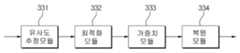
도 5는 본 발명의 일 실시 예에 따른 k-NN 기반 복원부(330)의 블록도이다.
도 6은 본 발명의 일 실시 예에 따른 이상 신호 복원 장치에서의 이상 신호 복원 방법을 도시한 도면이다.
도 7은 본 발명의 일 실시 예에 따른 이상 신호 복원 장치에서의 이상 신호 복원 방법의 복원 단계를 좀 더 구체적으로 도시한 도면이다.
도 8은 15개의 센서(태그) 데이터 중 2, 14, 15번 센서 데이터가 취득되지 않은 상황에서 해당 센서 데이터를 복원하는 것을 가정하는 시뮬레이션에 대한 결과를 도시한 도면이다.
도 9는 복원할 신호(태그)의 수가 1, 4, 7, 10개로 증가하는 경우의 복원의 정확도를 도시한 도면이다.
도 10은 복원할 신호(태그)의 수가 1, 4, 7, 10개로 증가하는 경우의 복원 후에도 이상 신호로 남아 있는 이상 신호의 수를 도시한 도면이다.1 is a block diagram of an abnormal signal recovery apparatus according to an embodiment of the present invention.
2 is a diagram illustrating an embodiment in which the
3 is a block diagram of the
4 is a block diagram of a
5 is a block diagram of a k-NN based
6 is a diagram illustrating a method of recovering an abnormal signal in the apparatus for recovering an abnormal signal according to an embodiment of the present invention.
7 is a diagram illustrating in more detail a restoration step of the abnormal signal restoration method in the abnormal signal restoration apparatus according to an embodiment of the present invention.
FIG. 8 is a diagram illustrating a result of a simulation assuming that the sensor data of 2, 14, and 15 of 15 sensor (tag) data is not acquired.
FIG. 9 is a diagram showing the accuracy of restoration when the number of signals (tags) to be restored increases to 1, 4, 7, 10. FIG.
FIG. 10 is a diagram showing the number of abnormal signals remaining as abnormal signals even after the recovery in the case where the number of signals (tags) to be restored increases to 1, 4, 7, 10. FIG.
본 발명을 명확하게 설명하기 위해서 설명과 관계없는 부분은 생략하였으며, 명세서 전체를 통하여 동일 또는 유사한 구성요소에 대해서는 동일한 참조 부호를 붙이도록 한다.In order to clearly describe the present invention, parts irrelevant to the description are omitted, and like reference numerals designate like elements throughout the specification.
명세서 전체에서, 어떤 부분이 다른 부분과 "연결"되어 있다고 할 때, 이는 "직접적으로 연결"되어 있는 경우뿐 아니라, 그 중간에 다른 소자를 사이에 두고 "전기적으로 연결"되어 있는 경우도 포함한다. 또한, 어떤 부분이 어떤 구성요소를 "포함"한다고 할 때, 이는 특별히 반대되는 기재가 없는 한 다른 구성요소를 제외하는 것이 아니라 다른 구성요소를 더 포함할 수 있는 것을 의미한다.Throughout the specification, when a part is "connected" to another part, this includes not only "directly connected" but also "electrically connected" with another element in between. . In addition, when a part is said to "include" a certain component, this means that it may further include other components, except to exclude other components unless otherwise stated.
어느 부분이 다른 부분의 "위에" 있다고 언급하는 경우, 이는 바로 다른 부분의 위에 있을 수 있거나 그 사이에 다른 부분이 수반될 수 있다. 대조적으로 어느 부분이 다른 부분의 "바로 위에" 있다고 언급하는 경우, 그 사이에 다른 부분이 수반되지 않는다.When a portion is referred to as being "above" another portion, it may be just above the other portion or may be accompanied by another portion in between. In contrast, when a part is mentioned as "directly above" another part, no other part is involved between them.
제1, 제2 및 제3 등의 용어들은 다양한 부분, 성분, 영역, 층 및/또는 섹션들을 설명하기 위해 사용되나 이들에 한정되지 않는다. 이들 용어들은 어느 부분, 성분, 영역, 층 또는 섹션을 다른 부분, 성분, 영역, 층 또는 섹션과 구별하기 위해서만 사용된다. 따라서, 이하에서 서술하는 제1부분, 성분, 영역, 층 또는 섹션은 본 발명의 범위를 벗어나지 않는 범위 내에서 제2부분, 성분, 영역, 층 또는 섹션으로 언급될 수 있다.Terms such as first, second, and third are used to describe various parts, components, regions, layers, and / or sections, but are not limited to these. These terms are only used to distinguish one part, component, region, layer or section from another part, component, region, layer or section. Accordingly, the first portion, component, region, layer or section described below may be referred to as the second portion, component, region, layer or section without departing from the scope of the invention.
여기서 사용되는 전문 용어는 단지 특정 실시 예를 언급하기 위한 것이며, 본 발명을 한정하는 것을 의도하지 않는다. 여기서 사용되는 단수 형태들은 문구들이 이와 명백히 반대의 의미를 나타내지 않는 한 복수 형태들도 포함한다. 명세서에서 사용되는 "포함하는"의 의미는 특정 특성, 영역, 정수, 단계, 동작, 요소 및/또는 성분을 구체화하며, 다른 특성, 영역, 정수, 단계, 동작, 요소 및/또는 성분의 존재나 부가를 제외하는 것은 아니다.The terminology used herein is for the purpose of describing particular embodiments only and is not intended to be limiting of the invention. As used herein, the singular forms “a,” “an,” and “the” include plural forms as well, unless the phrases clearly indicate the opposite. As used herein, the meaning of "comprising" embodies a particular characteristic, region, integer, step, operation, element and / or component, and the presence of other characteristics, region, integer, step, operation, element and / or component It does not exclude the addition.
"아래", "위" 등의 상대적인 공간을 나타내는 용어는 도면에서 도시된 한 부분의 다른 부분에 대한 관계를 보다 쉽게 설명하기 위해 사용될 수 있다. 이러한 용어들은 도면에서 의도한 의미와 함께 사용 중인 장치의 다른 의미나 동작을 포함하도록 의도된다. 예를 들면, 도면 중의 장치를 뒤집으면, 다른 부분들의 "아래"에 있는 것으로 설명된 어느 부분들은 다른 부분들의 "위"에 있는 것으로 설명된다. 따라서 "아래"라는 예시적인 용어는 위와 아래 방향을 전부 포함한다. 장치는 90˚ 회전 또는 다른 각도로 회전할 수 있고, 상대적인 공간을 나타내는 용어도 이에 따라서 해석된다.Terms indicating relative space such as "below" and "above" may be used to more easily explain the relationship of one part to another part shown in the drawings. These terms are intended to include other meanings or operations of the device in use with the meanings intended in the figures. For example, if the device in the figure is reversed, any parts described as being "below" of the other parts are described as being "above" the other parts. Thus, the exemplary term "below" encompasses both up and down directions. The device can be rotated 90 degrees or at other angles, the terms representing relative space being interpreted accordingly.
다르게 정의하지는 않았지만, 여기에 사용되는 기술용어 및 과학용어를 포함하는 모든 용어들은 본 발명이 속하는 기술분야에서 통상의 지식을 가진 자가 일반적으로 이해하는 의미와 동일한 의미를 가진다. 보통 사용되는 사전에 정의된 용어들은 관련 기술문헌과 현재 개시된 내용에 부합하는 의미를 가지는 것으로 추가 해석되고, 정의되지 않는 한 이상적이거나 매우 공식적인 의미로 해석되지 않는다.Unless defined otherwise, all terms including technical and scientific terms used herein have the same meaning as commonly understood by one of ordinary skill in the art. Commonly defined terms used are additionally interpreted to have a meaning consistent with the related technical literature and the presently disclosed contents, and are not interpreted in an ideal or very formal sense unless defined.
이하, 첨부한 도면을 참조하여 본 발명의 실시예에 대하여 본 발명이 속하는 기술분야에서 통상의 지식을 가진 자가 용이하게 실시할 수 있도록 상세히 설명한다. 그러나 본 발명은 여러 가지 상이한 형태로 구현될 수 있으며 여기에서 설명하는 실시 예에 한정되지 않는다.DETAILED DESCRIPTION Hereinafter, exemplary embodiments of the present invention will be described in detail with reference to the accompanying drawings so that those skilled in the art may easily implement the present invention. As those skilled in the art would realize, the described embodiments may be modified in various different ways, all without departing from the spirit or scope of the present invention.
본 발명에 대해 설명을 시작하기 전에 먼저 태그(Tag)에 대하여 정의한다. 태그는 플랜트에서 측정할 수 있는 신호의 종류를 의미할 수 있다. 일 예로, 인렛 필터(Inlet Filter)의 차압, Turbine Exhaust 압력, 온도와 같이 센서를 이용하여 플랜트에서 직접적으로 획득할 수 있는 신호 종류뿐만 아니라 출력 파워처럼 시스템에서 센서를 이용하여 획득한 신호를 바탕으로 계산한 값을 의미할 수 있다.Before describing the present invention, a tag is first defined. The tag may refer to a kind of signal that can be measured by the plant. For example, based on the signal obtained by using the sensor in the system, such as the output power, as well as the signal type that can be obtained directly from the plant using the sensor such as the differential pressure of the inlet filter, the turbine exhaust pressure, and the temperature. It can mean a calculated value.
도 1은 본 발명의 일 실시 예에 따른 이상 신호 복원 장치의 블록도이다.1 is a block diagram of an abnormal signal recovery apparatus according to an embodiment of the present invention.
도 1을 참조하면, 본 발명에 따른 이상 신호 복원 장치는, 데이터처리부(100), 모델링부(200), 복원부(300)를 포함할 수 있다.Referring to FIG. 1, the abnormal signal restoration apparatus according to the present invention may include a
데이터처리부(100)는 이상신호를 복원하기 위해 사전에 데이터를 처리하는 모듈이다. 데이터처리부(100)는 3개의 데이터(X, U, S)를 입력으로 받아들 일수 있는데, 신호그룹 X는 기존의 고장 예측 모델을 만들기 위해 사용된 학습 데이터를 나타내며, 모두 정상인 신호를 포함하고 있다. 신호그룹 U는 복원하고자 하는 태그가 포함되어 있는 데이터이다. 즉, 신호그룹 U의 일부 태그는 이상 신호를 포함하고 있는 데이터이며, 신호그룹 U에 포함되어 있는 이상 신호를 가지고 있는 일부 태그가 정상 신호를 가지도록 복원하여 학습 데이터로 사용할 수 있게 만들고자 하는 것이다. 입력 S는 복원하고자 하는 태그에 대한 정보를 포함하고 있는 입력이다.The
도 2는 데이터처리부(100)가 신호그룹 X, U, 및 입력 S를 받아 신호그룹 X*, Xs, 및 U*를 생성하는 일 실시 예를 도시한 도면이다.2 is a diagram illustrating an embodiment in which the
도 2를 참조하면, 데이터처리부(100)의 입력과 출력은 모두 행렬 형태로 나타날 수 있다. 신호그룹 X(110)는 기존의 고장 예측 모델을 만들기 위해 사용된 학습 데이터를 나타내는 것으로 각 행은 플랜트에서 측정하는 신호의 종류, 즉 태그일 수 있다. 그리고 각 열은 각 태그가 가지는 값을 시간 순서로 나타낸 것이다. 일 예로서 각 센서를 통하여 신호를 5분에 한번씩 획득할 수 있는데 이렇게 획득한 값은 각 태그의 열에 표시할 수 있다. 그러면 15x2000 행렬인 도 2의 신호그룹 X(110)는 15개의 신호 종류에 대하여 종류별로 2000번 획득한 값(시간상으로는 7일)을 나타내고 있다. 여기서 신호그룹 X(110)는 기존의 고장 예측 모델을 만들 때 사용한 것으로 행렬 내의 모든 값은 정상적인 값이 된다.Referring to FIG. 2, both the input and the output of the
신호그룹 U(120)는 새롭게 측정한 데이터이다. 즉, 도 2의 예에서는 15개의 태그에 대하여 3.5일 정도의 기간에 5분마다 하나의 신호 값을 획득하여 신호그룹 U(120)를 생성할 수 있다. 그런데 획득한 신호그룹 U(120)를 바탕으로 고장 예측을 수행해 본 결과 10, 14, 15번 태그에 문제가 있음을 알게 되었다. 이러한 문제는 플랜트에 고장이 발생하여 생길 수도 있지만 센서가 동작하지 않거나, 관측한 신호 값을 전달하는 네트워크에 문제가 있어서 생길 수도 있다. 어느 태그에 문제가 있는 지를 확정하는 것은 본 발명과는 상관이 없는 것으로 여기서는 더는 언급하지 않고 특정 태그에 문제가 있음을 입력 S(130)를 통해 알고 있다고 상정한다.
신호그룹 U(120)는 15개의 태그 중 12개의 태그에 대하여는 정상 신호를 가지고 있지만 3개의 태그에 대하여는 이상 신호를 가지고 있다. 이런 경우 종래에는 신호그룹 U(120)를 모두 버려야 하지만 3.5일동안 수집한 데이터가 사라지게 되는 것이므로 고장 예측 모델을 생성하고 실행하는데 비효율성이 발생할 수 있다. 그래서 본 발명은 이러한 비효율을 없애기 위해 이상 신호를 가지고 있는 태그를 정상 신호를 가지도록 복원하여 신호그룹 U(120)를 학습 데이터에 사용할 수 있게 함으로써 수집한 데이터의 낭비를 없애고, 고장 예측 모델 생성에 효율성을 기할 수 있다.
정리하면 신호그룹 U(120)는 이상 신호를 포함, 즉 복원하고자 하는 태그가 포함되어 있는 데이터로 볼 수 있다.In summary, the
그리고 입력 S(130)는 이상 데이터를 포함하고 있어 복원이 필요한 태그에 대한 정보를 포함하고 있다. 도 2의 예에서는 신호그룹 U(120)의 태그 중 10, 14, 및 15번 태그가 이상 신호를 가지고 있음을 나타낸다.The input S 130 includes abnormal data and thus includes information on a tag that needs to be restored. In the example of FIG. 2, tags 10, 14, and 15 of the tags of the
데이터처리부(100)는 신호그룹 X(110), U(120), 및 입력 S(130)를 받아 신호그룹 X*(140), Xs(150), 및 U*(160)를 생성할 수 있다. 신호그룹 X*(140)는 신호그룹 X(110)에서 복원하고자 하는 태그를 제외한 나머지 태그(이하 제2 태그그룹)에 해당하는 신호만을 포함하고, 신호그룹 U*(160)는 신호그룹 U(120)에서 제2 태그그룹에 해당하는 신호만을 포함하고. 즉, 도 2의 예에서, 신호그룹 X(110)에서 복원하고자 하는 신호 태크인 10, 14, 15번 행을 제외한 12x2000의 행렬이 신호그룹 X*(140)가 되고, 신호그룹 U(120)에서 복원하고자 하는 신호 태그인 10, 14, 15번 행을 제외한 12x1000의 행렬이 신호그룹 U*(160)가 된다. 그리고 신호그룹 Xs(150)는 신호그룹 X(110)에서 복원하고자 하는 태그(제 1 태그그룹)에 해당하는 신호만을 포함한다. 즉, 도 2의 예에서, 신호그룹 Xs(150)는 10, 14, 및 15번 행의 데이터를 가지는 3x2000 행렬이 된다.The
이렇게 데이터처리부(100)에서 출력된 신호그룹 X*, U*, 및 Xs는 모델링부(200)와 복원부(300)로 입력되어 사용될 수 있다.The signal groups X *, U *, and Xs output from the
전술한 일 실시 예에서 신호그룹 X는 데이터 처리부(100)에서 신호그룹 X*와 Xs로 분리될 수 있는 것으로 되어 있지만 이는 부가적인 것으로 이상 신호 복원 장치의 다른 부분에서는 데이터 처리부(100)에서 처리되지 않은 신호그룹 X를 이용하여 기능을 수행할 수 있음도 당연할 것이다.In the above-described embodiment, the signal group X may be separated into the signal group X * and Xs in the
도 3은 본 발명의 일 실시 예에 따른 모델링부(200)의 블록도이다.3 is a block diagram of the
도 3을 참조하면, 모델링부(200)는 제1 태그그룹의 이상 신호를 복원하기 위한 모델을 생성하는 기능을 수행하는 것으로, 특징추출부(210)와 모델생성부(220)를 포함할 수 있으며, 입력으로 데이터처리부(100)에서 생성한 신호그룹 X*와 Xs를 사용하고, 출력으로 추출된 특징 정보를 포함하는 F와 생성된 복원 모델 정보를 포함하는 P를 출력할 수 있다.Referring to FIG. 3, the
특징추출부(210)는 신호그룹 X*를 바탕으로 데이터가 나타내고 있는 특징을 추출할 수 있다. 이때 특정 하나의 태그 데이터만을 이용하여 추출할 수도 있고, 신호그룹 X*에 포함되어 있는 전체 태그에 대한 데이터, 또는 일부 태그에 대한 데이터를 조합하여 추출할 수도 있다. 이때 추출되는 특징은, 발전기가 기동 상태에 있는 지 아니면 정상 상태로 운전하고 있는 지를 나타낼 수도 있고, 데이터를 수집한 계절이 봄, 여름, 가을 및 겨울 중에서 어느 계절인지를 나타낼 수도 있으며, 또는 특정 날씨를 나타낼 수도 있다. 이외에도 플랜트에서 생성되는 데이터로부터 얻을 수 있는 다양한 특징들이 추출될 수 있다.The
모델생성부(220)는 다양한 복수 개의 모델을 생성할 수 있다. 이러한 모델들은 비모수성 모델(Non parametric model)일 수도 있고, 모수성 모델(Parametric model)일 수 있다. 즉, 도 2를 참조하면, 모델생성부(220)는 특징추출부(210)에서 추출한 특징 F를 기반으로 데이터처리부(100)로부터 받은 신호그룹 X*와 Xs를 이용하여 복수의 비모수성 모델 및 모수성 모델을 생성할 수 있다.The
모수성 모델은 유한 개의 파라미터를 이용하여 시스템을 나타내는 모델이다. 즉, 모수성 모델은 한정된 몇 개의 파라미터를 이용하여 시스템을 묘사할 수 있다. 이러한 모수성 모델에는 제1원칙 모델(First Principles based Model), 전달함수모델(Transfer Function Model), 상태공간모델(State Space Model) 등이 있다. 여기서 제1원칙 모델은 기초적이고 기본적인 물리학 제1 법칙에 의해 정해지는 것들을 파라미터로 사용하는 모델이고, 상태공간모델은 상태 변수를 파라미터로 사용하는 모델이고, 전달함수모델은 입력과 출력 간의 전달함수를 규정하는 변수들을 파라미터로 사용하는 모델일 수 있다. 여기서 전달함수모델은 ARX(Auto Regressive eXogenous), NARX(Nonlinear Auto Regressive eXogenous), FIR(Finite Impulse Response), ARMAX(Auto Regressive Moving Average with eXogenous) 모델 등이 포함될 수 있다.The parametric model is a model representing a system using finite number of parameters. In other words, the parametric model can describe the system using a limited number of parameters. Such parametric models include a First Principles based Model, a Transfer Function Model, and a State Space Model. In this case, the first principle model is a model using parameters defined by the first and fundamental laws of physics, the state space model is a model using state variables as a parameter, and the transfer function model is a transfer function between input and output. It can be a model that uses defining variables as parameters. The transfer function model may include ARX (Auto Regressive eXogenous), NARX (Nonlinear Auto Regressive eXogenous), Finite Impulse Response (FIR), and ARMAX (Auto Regressive Moving Average with eXogenous) models.
비모수성 모델은 플랜트를 표현하기 위하여 무한 개의 파라미터를 사용할 수 있는 모델로서 NPM(Non Parametric Model), TM(Tree Model), NNM(Neural Network Model) 등이 포함될 수 있다. 비록 비모수성 모델이 개념상 무한 개의 파라미터를 사용할 수 있지만 실제로는 유한 개만을 사용하여 모델을 표현한다.The non-parametric model is a model that can use an infinite number of parameters to represent a plant may include a non parametric model (NPM), a tree model (TM), a neural network model (NNM). Although a nonparametric model can conceptually use an infinite number of parameters, it actually represents only a finite number of models.
모델생성부(200)는 특징추출부(210)에서 추출한 특징을 기반으로 신호그룹 X*와 Xs를 이용하여 하나 이상의 모수성 모델에 대하여 각 모델을 최적화하는 파라미터를 결정할 수 있고, 또한 하나 이상의 비모수성 모델에 대하여 각 모델을 최적화하는 파라미터를 결정할 수 있다. 이렇게 결정된 파라미터들은 모델 정보 P에 포함될 수 있다. 즉, 모델 정보 P는 최적화된 복수개의 모수성 모델 및/또는 비모수성 모델과 각 모델에서 사용하게 될 파라미터 정보를 포함할 수 있다.The
이때 모델링부(200)에서 특징 정보를 기반으로 복수의 모델을 구성하는 이유는 보다 정확한 복원이 가능하기 때문이다.In this case, the reason why the
도 4는 본 발명의 일 실시 예에 따른 복원부(300)의 블록도이다.4 is a block diagram of a
복원부(300)는 모델의 표현력을 극대화시키고, 특정 태그에 대한 데이터들이 다른 태그에 대한 데이터에 미치는 영향을 최소화시키기 위하여, 모델 기반의 복원이 아닌 알고리즘 기반의 복원 기술인 k-NN(k-Nearest Neighbor)기반의 복원 알고리즘을 사용할 수 있다. 동시에 알고리즘 기반 복원 기술이 갖고 있는 단점을 극복하고 범용성을 향상시키기 위하여 모델 기반의 복원 기술 중 하나인 MLRM(Multiple Linear Regression Model) 기반의 복원 알고리즘을 사용할 수 있다.The
도 4를 참조하면, 복원부(300)는 특징추출부(310), 복원모델조합부(320), k-NN 기반 복원부(330), MLRM 기반 복원부(340), 및 앙상블 학습부(350)를 포함할 수 있다.Referring to FIG. 4, the
특징추출부(310)는 신호그룹 U* 데이터에 포함되어 있는 특징 F*를 추출할 수 있다. 특징추출부(310)에서 사용하는 특징 추출의 기준과 로직은 전술한 모델링부(200)의 특징추출부(210)에서 사용하는 특징 추출의 기준과 로직을 동일하게 사용하여 특징을 추출할 수 있다.The
복원모델조합부(320)는 모델링부(200)에서 생성된 특징 정보 F와 모델 정보 P 및 특징추출부(310)에서 추출한 신호그룹 U*의 특징 정보 F*를 기반으로 복원에 사용될 최적의 복원 모델들을 선택할 수 있다. 특히 하나 이상의 비모수성 모델과 하나 이상의 모수성 모델을 선택할 수 있다. 복원모델조합부(320)에서 최적의 복원 모델을 선택 시에 모델링부(200)의 특징추출부(210)에서 추출한 특징 정보 F와 복원부(300)의 특징추출부(310)에서 추출한 특징 정보 F*를 서로 비교하여 유사한 영역을 찾고, 유사한 영역에서 유사한 특징을 생성하는 복원모델들을 최적의 복원 모델로 선택할 수 있다.The reconstruction
복원모델조합부(320)에서 선택한 복원 모델을 이용하여 k-NN 기반 복원부(330)및 MLRM기반 복원부(340)에서 복원값을 계산할 수 있다.The k-NN-based
k-NN 기반 복원부(330)는 k개의 최근접 이웃한 데이터의 평균 값으로 복원값을 계산할 수 있다.The k-NN based
도 5는 본 발명의 일 실시 예에 따른 k-NN 기반 복원부(330)의 블록도이다.5 is a block diagram of a k-NN based
본 발명에서 제시하는 k-NN 기반 복원부(330)는 유사성을 계산하는 유사도추정모듈(331), k를 최적화하는 최적화모듈(332), 각 객체 별(만약 복수 개의 복원모델을 이용하는 경우, 각 복원모델이 객체가 될 수 있다) 가중치를 계산하는 가중치모듈(333), 및 복원값을 계산하는 복원모듈(334)을 포함할 수 있다. 유사도추정모듈(331)은 복원모델조합부(320)에서 선정한 최적의 복원 모델을 기반으로, Xs와의 유사성을 나타내는 유사도를 계산할 수 있고, 이후 최적화모듈(332)은 최적화 알고리즘을 이용하여 복원에 사용될 객체(particle)의 개수 k를 최적화할 수 있다.The k-NN based
그리고 객체별 가중치를 계산하는 가중치모듈(333)은 전술한 유사도를 바탕으로 객체별 가중치를 계산하고, 복원모듈(334)은 이렇게 가중화된 k개의 개체를 바탕으로 k-NN 알고리즘을 사용하여 복원을 수행할 수 있다.The
MLRM기반 복원부(340)는 복원모델조합부(320)에서 선택한 복원 모델을 기반으로 복원값을 계산할 수 있다. 이때 복원 모델을 위한 입력이 필요하므로 U*를 이에 대한 입력으로 사용할 수 있다. MLRM은 다중선형회귀 모델을 의미하는 것으로 종속변수(본 발명에서는 복원값)가 복수 개의 독립변수(본 발명에서는 복원모델조합부(320)에서 선정한 복원모델에 의해 결정된 복원값)에 의해서 결정되는 것을 의미한다. 이때 각 독립변수별 가중치를 두고 종속변수를 결정할 수도 있다.The MLRM-based
전술한 k-NN 기반 복원부(330)와 MLRM 기반 복원부(340)에서 결정된 복원값들은 앙상블학습부(350)로 전달될 수 있다.The restoration values determined by the k-NN-based
앙상블학습부(350)는 k-NN 기반 복원부(330)와 MLRM 기반 복원부(340)에서 결정된 복원값들을 바탕으로 최적 복원값을 추출할 수 있다. 앙상블학습은 따로 쓰는 경우에 비해 더 좋은 성능을 얻기 위해 복수의 학습 알고리즘을 이용하는 것을 말한다. 본 발명에서는 복원값의 정확도를 높이기 위하여 서로 특성이 다른 복수의 복원 모델과 복원 알고리즘을 선정하고 복수의 복원 알고리즘을 통해 추정된 복원값을 바탕으로 최적 복원값을 추정하기 위하여 앙상블 학습을 사용하도록 하였다.The
앙상블학습부(350)는 k-NN 기반 복원부(330)와 MLRM 기반 복원부(340)에서 추정한 복원값들을 바탕으로 가장 정확한 복원값을 추정하기 위하여 다양한 알고리즘 방식을 사용할 수 있는데 각 복원값에 가중치를 곱함이 없이 다수결에 의한 배깅(bagging) 방식, 또는 각 예측 모델에서 추정한 예측치에 가중치를 곱하고 더하여서 추정하는 가중치 투표(boosting) 방식 등이 있을 수 있다.The
도 6은 본 발명의 일 실시 예에 따른 이상 신호 복원 장치에서의 이상 신호 복원 방법을 도시한 도면이다.6 is a diagram illustrating a method of recovering an abnormal signal in the apparatus for recovering an abnormal signal according to an embodiment of the present invention.
도 6을 참조하면, 이상 신호 복원 장치에서의 이상 신호 복원 방법은 먼저 데이터처리부(100)에서 입력되는 데이터를 처리하여 이상 신호를 삭제(S510)할 수 있다. 이상 신호 복원 장치에 입력되는 데이터는 3개(X, U, S)일 수 있는데, 신호 그룹 X는 기존의 고장 예측 모델을 만들기 위해 사용된 학습 데이터로 태그에 대하여 모두 정상값을 가지는 신호 그룹을 나타내며, 입력 신호 그룹 U는 복원하고자 하는 신호 태그가 포함되어 있는 신호그룹이다. 즉, 입력 U는 일부 태그(제1 태그그룹)에 이상 신호를 포함하고 있는 신호그룹이며, 입력 U에 포함되어 있는 제1 태그그룹에 대한 정상 신호를 복원하여 학습 데이터로 사용할 수 있게 만들고자 하는 것이다. 입력 S는 복원하고자 하는 태그 정보를 포함하고 있는 신호이다. 여기서 신호그룹 X와 신호그룹 U는 태그별로 시간 순서로 획득한 값을 기재한 행렬일 수 있다. 이때 행은 센서를 이용하여 관측한 또는, 센서로부터 획득한 값을 이용하여 계산한 신호의 종류(태그라 칭함)를 나타내고 열은 각 태그에서 시간순서 상으로 획득한 태그의 값을 나타낼 수 있다. 데이터처리부(100)는 입력 S로부터 이상 신호가 포함된 태그 즉, 복원하고자 하는 태그(제1 태그그룹) 정보를 획득하고 이를 이용하여 입력 U로부터 복원하고자 하는 태그에 대한 데이터를 제외한 나머지 태그(제2 태그그룹)에 해당하는 신호만을 포함하는 신호그룹 U*를 생성할 수 있다. 이때 신호그룹 U*에 포함되어 있는 신호는 정상 신호이다. 신호그룹 U에서 신호그룹 U*를 생성하면서 이상 신호가 삭제된다.Referring to FIG. 6, in the abnormal signal restoration method of the apparatus for recovering an abnormal signal, first, an abnormal signal may be deleted by processing data input from the data processor 100 (S510). The data input to the anomaly signal recovery apparatus may be three (X, U, S), and the signal group X is training data used to create an existing failure prediction model. The input signal group U is a signal group including a signal tag to be restored. That is, the input U is a signal group including an abnormal signal in some tags (first tag group), and is intended to restore the normal signal for the first tag group included in the input U to be used as learning data. . The input S is a signal containing tag information to be restored. Here, the signal group X and the signal group U may be matrixes describing values obtained in a time order for each tag. In this case, the row may indicate the type (signal) of the signal observed using the sensor or calculated using the value obtained from the sensor, and the column may indicate the value of the tag acquired in each tag in time order. The
이에 더하여, 데이터처리부(100)는 부가적으로 신호그룹 X에서 제2 태그그룹에 해당하는 신호만을 포함하는 신호그룹 X* 및 신호그룹 X에서 제1 태그그룹에 해당하는 신호만을 포함하는 신호그룹 Xs로 분리하여 생성할 수 있다. 이때 신호그룹 X*와 Xs에 포함되어 있는 신호들은 모두 정상적인 신호이다.In addition, the
일 예로서 신호그룹 X는 15개의 태그를 가지고 태그별 2000개의 태그 값을 가지는 15x2000 행렬일 수 있고, 신호그룹 U는 신호그룹 X와 동일한 15개의 태그를 가지고 태그별 1000개의 태그 값을 가지는 15x1000 행렬일 수 있다. S는 복원하고자 하는 태그(제1 태그그룹) 정보를 가지고 있는 것으로, 도 2의 일 실시 예에서는 10, 14, 15번 열의 태그가 복원하고자 하는 태그일 수 있다. 그러면 신호그룹 X*는 신호그룹 X에서 10, 14, 15번 행이 삭제된 12x2000 행렬이 되고, 신호그룹 Xs는 10, 14, 14번 행으로만 구성된 3x2000 행렬이 된다. 그리고 신호그룹 U*는 신호그룹 U에서 10, 14, 15번 행이 삭제된 12x1000 행렬이 된다.As an example, the signal group X may be a 15x2000 matrix having 15 tags and 2000 tag values per tag, and the signal group U has 15 tags identical to the signal group X and has a 15x1000 matrix having 1000 tag values per tag. Can be. S has tag (first tag group) information to be restored. In an embodiment of FIG. 2, the tags in
이렇게 데이터처리부(100)에서 생성된 데이터를 바탕으로 모델링부(200)는 신호 특징 정보 및 복수의 복원 모델을 생성(S520)할 수 있다. 모델링부(200)가 복수의 복원모델을 생성하기 위하여 먼저, 특징추출부(210)에서 신호그룹 X*를 바탕으로 신호가 나타내고 있는 특징을 추출할 수 있다. 이때 특정 하나의 태그 데이터만을 이용하여 추출할 수도 있고, 신호그룹 X*에 포함되어 있는 전체 태그에 대한 신호, 또는 일부 태그에 대한 신호를 조합하여 추출할 수도 있다. 이때 추출되는 특징은, 발전기가 기동 상태에 있는지 아니면 정상 상태로 운전하고 있는 지를 나타낼 수도 있고, 데이터를 수집한 계절이 봄, 여름, 가을 및 겨울 중에서 어느 계절인지를 나타낼 수도 있으며, 또는 특정 날씨를 나타낼 수도 있다. 이외에도 플랜트에서 생성되는 데이터로부터 얻을 수 있는 다양한 특징들이 추출될 수 있다. The
모델생성부(220)는 특징추출부(210)에서 추출한 특징 정보 F를 기반으로 데이터처리부(100)로부터 전달받은 신호그룹 X*와 Xs를 이용하여 복수의 비모수성 모델 및 모수성 모델을 생성할 수 있다.The
복원부(300)는 모델생성부(220)와 데이터처리부(100)로부터 받은 정보를 바탕으로 제1 태그그룹에 대한 정상 신호를 추정하고 복원(S530)할 수 있다.The
도 7은 본 발명의 일 실시 예에 따른 이상 신호 복원 장치에서의 이상 신호 복원 방법의 복원 단계를 좀 더 구체적으로 도시한 도면이다.7 is a diagram illustrating in more detail a restoration step of the abnormal signal restoration method in the abnormal signal restoration apparatus according to an embodiment of the present invention.
도 7을 참조하여 복원 단계를 좀 더 구체적으로 살펴보면, 복원부(300)의 복원모델조합부(320)는 모델링부(200)의 특징추출부(210)와 유사하게 신호그룹 U*로부터 특징 정보 F*를 추출(S531)할 수 있다. 그리고 모델링부(200)의 특징추출부(210)에서 추출한 특징 정보 F와 복원부(300)의 특징추출부(310)에서 추출한 특징 정보 F*를 서로 비교하여 유사한 영역을 찾고, 유사한 영역에서 유사한 특징을 생성하는 복원모델들을 최적의 복원 모델로 선택(S532)하고 이후 이상 신호 복원을 위하여 사용할 수 있다.Referring to FIG. 7 in more detail, the restoration
복원모델조합부(320)에서 선택한 복원 모델을 이용하여 k-NN 기반 방식(S533) 및 MLRM 기반 방식(S534)으로 복원값을 생성할 수 있다.The reconstruction model selected by the reconstruction
k-NN 기반 방식(S533)은 k개의 최근접 이웃한 데이터의 평균값으로 복원값을 계산하여 생성할 수 있다. K-NN 기반 방식은 유사성을 계산하는 부분, k를 최적화 하는 부분, 각 객체 별(만약 복수 개의 비모수성 모델을 이용하는 경우, 각 비모수성 모델이 객체가 될 수 있다) 가중치를 계산하는 부분, 및 복원값을 계산하는 부분을 포함할 수 있다. 유사성을 계산하는 부분은 복원모델조합부(320)에서 선정한 최적의 복원 모델을 기반으로, 신호그룹 Xs와의 유사성을 나타내는 유사도를 계산할 수 있고, 이후 최적화 알고리즘을 이용하여 복원에 사용될 객체(particle)의 개수 k를 최적화할 수 있다. 그리고 객체별 가중치를 계산하는 부분은 전술한 유사도를 바탕으로 객체별 가중치를 계산하고, 이렇게 가중화된 k개의 개체를 바탕으로 k-NN 알고리즘을 사용하여 복원값을 계산할 수 있다.The k-NN based method S533 may be generated by calculating a restored value as an average value of k nearest neighbor data. The K-NN-based method calculates the similarity, optimizes k, calculates the weight for each object (if using a plurality of non-parametric models, each non-parametric model can be an object), and It may include a part for calculating the restored value. The part of calculating the similarity may calculate the similarity indicating the similarity to the signal group Xs based on the optimal reconstruction model selected by the reconstruction
MLRM기반 방식(S534)은 복원모델조합부(320)에서 선택한 복원 모델을 기반으로 복원값을 계산할 수 있다. 이때 복원 모델을 위한 입력이 필요하므로 신호그룹 U*를 이에 대한 입력으로 사용할 수 있다. MLRM은 다중선형회귀 모델을 의미하는 것으로 종속변수(본 발명에서는 복원값)가 복수 개의 독립변수(본 발명에서는 복원모델조합부(320)에서 선정한 복원모델에 의해 결정된 복원값)에 의해서 결정되는 것을 의미한다. 이때 각 독립변수별 가중치를 두고 종속변수를 결정할 수도 있다.The MLRM-based method S534 may calculate a restoration value based on the restoration model selected by the restoration
마지막으로 k-NN 기반 방식과 MLRM 기반 방식에 의한 결정된 복원값들을 바탕으로 앙상블 학습을 이용하여 최적 복원값을 생성(S535)할 수 있다. 앙상블학습은 따로 쓰는 경우에 비해 더 좋은 성능을 얻기 위해 복수의 학습 알고리즘을 이용하는 것을 말한다. 본 발명에서는 복원값의 정확도를 높이기 위하여 서로 특성이 다른 복수의 복원 모델을 선정하고 각 복원 모델에서의 복원값을 바탕으로 최적 복원값을 추정하기 위하여 앙상블 학습을 사용하도록 하였다.Finally, based on the reconstructed values determined by the k-NN based method and the MLRM based method, an optimal reconstructed value may be generated using ensemble learning (S535). Ensemble learning is the use of multiple learning algorithms to achieve better performance than writing separately. In the present invention, a plurality of reconstruction models having different characteristics are selected to increase the accuracy of reconstruction values, and ensemble learning is used to estimate an optimal reconstruction value based on reconstruction values in each reconstruction model.
본 발명에 의한 이상 신호 복원 방법에 의하면 복원 성능을 획기적으로 높일 수 있다. 본 발명의 우수성을 검증하기 위하여, GE사의 SmartSignal에 탑재되어 있는 Virtual Signal Generation (VSG) 기능과 일반적인 k-NN 기반의 기술을 이용하여 신호를 복원하는 방법과 본 발명에서 제안하는 방법과의 성능을 시뮬레이션을 이용하여 비교하여 보았다.According to the abnormal signal restoration method according to the present invention, the restoration performance can be significantly improved. In order to verify the superiority of the present invention, the performance of the signal recovery method using the Virtual Signal Generation (VSG) function of GE's SmartSignal and general k-NN-based technology and the method proposed by the present invention Comparison was made using simulation.
<시뮬레이션 1><
첫 번째 시뮬레이션은 15개의 센서(태그) 데이터 중 2, 14, 15번 센서 데이터가 취득되지 않은 상황에서 해당 센서 데이터를 복원하는 것을 가정하였다. 표 1은 본 시뮬레이션 결과를 나타낸다. 여기서 사용한 성능 지표는 정확도와 이상 신호 수로 나타냈으며, 정확도는 얼마나 정확하게 복원이 되었는지를 의미하며, 이상 신호는 정확하게 복원되지 않은 신호의 개수를 의미한다. 정확하게 복원이 되었는지 되지 않았는지에 대한 기준은 해당 센서 데이터의 최대값의 3%를 계산하여 기준치를 설정하였고, 이 기준치를 기반으로 하여 복원된 신호의 예측 값이 실제 값의 기준치 내에 들어오게 되면 정확하게 복원되었다고 판단하였다.In the first simulation, it is assumed that the sensor data of 2, 14, and 15 of 15 sensor (tag) data are not acquired. Table 1 shows the results of this simulation. The performance indicators used here are expressed in terms of accuracy and the number of abnormal signals, and the accuracy indicates how accurately the signal is restored, and the abnormal signal means the number of signals that are not correctly recovered. The criterion of whether the restoration was correctly or not was set by setting the reference value by calculating 3% of the maximum value of the sensor data, and based on this reference value, if the prediction value of the restored signal falls within the reference value of the actual value, It was judged.
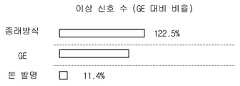
도 8은 15개의 센서(태그) 데이터 중 2, 14, 15번 센서 데이터가 취득되지 않은 상황에서 해당 센서 데이터를 복원하는 것을 가정하는 시뮬레이션에 대한 결과를 도시한 도면이다.FIG. 8 is a diagram illustrating a result of a simulation assuming that the sensor data of 2, 14, and 15 of 15 sensor (tag) data is not acquired.
도 8 및 표 1을 참조하면, 정확도는 GE의 경우 84.7%, 기존의 k-NN의 경우에는 81.3%를 나타내는 반면에, 본 발명에서 제안한 방법은 98.3%를 나타내어 본 발명에서 제시한 방법의 성능이 매우 우수함을 알 수 있다. 또한, 부정확하게 복원된 신호 수를 보면, GE는 458개, 기존의 k-NN은 561개이지만, 본 발명에서 제시한 방법은 52개로 GE 대비 11.4% 수준임을 알 수 있다.Referring to Figure 8 and Table 1, the accuracy is 84.7% for GE, 81.3% for the existing k-NN, while the method proposed in the present invention is 98.3%, the performance of the method proposed in the present invention It can be seen that this is very excellent. In addition, the number of incorrectly reconstructed signals indicates that the number of GEs is 458 and the existing k-NN is 561, but the number of proposed methods is 52, which is 11.4% compared to GE.
<시뮬레이션 2><
이번 시뮬레이션에서는 복원할 센서 데이터의 수를 하나씩 늘려서 복원 센서 수가 늘어남에 따라 복원성능이 어떻게 변화하는지를 살펴 보고자 하였다. 복원을 해야 할 신호의 수가 늘어난다고 하는 것은 복원에 필요한 정보 데이터가 줄어든다는 것을 의미하기 때문에 일반적으로 복원 성능이 떨어질 수밖에 없다. 하지만, 이런 상황에서도 질 좋은 학습 데이터를 확보하기 위해서는 복원 성능을 극대화할 필요가 있다.In this simulation, we tried to see how the restoration performance changes as the number of restoration sensors increases by increasing the number of sensor data to be restored one by one. Increasing the number of signals to be restored means that the information data necessary for the restoration is reduced, and therefore, the restoration performance generally decreases. However, even in this situation, it is necessary to maximize the restoration performance in order to obtain quality training data.
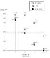
도 9는 복원할 신호(태그)의 수가 1, 4, 7, 10개로 증가하는 경우의 복원의 정확도를 도시한 도면이다.FIG. 9 is a diagram showing the accuracy of restoration when the number of signals (tags) to be restored increases to 1, 4, 7, 10. FIG.
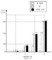
도 10은 복원할 신호(태그)의 수가 1, 4, 7, 10개로 증가하는 경우의 복원 후에도 이상 신호로 남아 있는 이상 신호의 수를 도시한 도면이다.FIG. 10 is a diagram showing the number of abnormal signals remaining as abnormal signals even after the recovery in the case where the number of signals (tags) to be restored increases to 1, 4, 7, 10. FIG.
표 2는 복원할 신호(태그)의 수가 1, 4, 7, 10개로 증가하는 경우의, 복원 성능의 변화를 나타낸 것이다.Table 2 shows the change in the restoration performance when the number of signals (tags) to be restored increases to 1, 4, 7, 10.
도 9 및 표 2를 참조하면, 복원한 태그의 수가 1개일 경우에는 본 발명에서 제안한 방법과 GE의 결과가 각각 98.8%, 95.3%로 큰 차이가 나지는 않지만 복원할 태그의 수가 4개로 늘어날 경우, 본 발명에서 제안한 방법에 의하면 97.9%의 정확도를 가지게 되어 1개일 때와 큰 차이가 나지 않는 반면에 GE의 경우에는 82.9%로 성능이 크게 저하됨을 알 수 있다. 그리고 7개/10개일 경우 본 발명에서 제안한 발명과 GE에서 제안한 발명은 각각 82.9%/76.0%와 67.9%/60.7%의 성능이 나옴을 알 수 있다. 이 결과를 보면 알 수 있듯이, 복원되어야 하는 태그의 수가 많아질수록 복원에 필요한 정보의 수가 줄어들기 때문에 성능이 저하되는 것은 피할 수 없다. 하지만, 본 발명에서 제안한 방법은 그 저하 폭이 크지 않은 반면에 GE의 경우에는 매우 크다는 것을 알 수 있다.Referring to FIG. 9 and Table 2, when the number of restored tags is one, the method proposed in the present invention and the results of GE are not significantly different to 98.8% and 95.3%, respectively, but when the number of tags to be restored increases to four, According to the method proposed in the present invention, the accuracy of 97.9% is not significantly different from that of one, whereas in the case of GE, it can be seen that the performance is greatly reduced to 82.9%. In the case of 7/10, the invention proposed by the present invention and the GE proposed invention can be seen that the performance of 82.9% / 76.0% and 67.9% / 60.7%, respectively. As can be seen from this result, as the number of tags to be restored increases, the number of information required for restoration decreases, so that performance is inevitable. However, it can be seen that the proposed method of the present invention does not have a large drop, but is very large for GE.
또한, 도 10 및 표 2를 참조하면, 정확하게 복원되지 않은 이상 신호 수는 복원할 태그의 수가 1->4->7->10개로 증가함에 따라 GE의 경우에는 47->684->2244->3927개가 되고, 본 발명에서 제시한 방법을 이용한 경우에는 12->84->715->2402개로 GE 대비 정확하게 복원되지 않은 신호의 개수가 매우 적다는 것을, 즉 매우 정확하게 신호를 복원할 수 있다는 것을 알 수 있다.10 and Table 2, the number of abnormal signals that are not correctly restored is 47-> 684-> 2244- in the case of GE as the number of tags to be restored increases from 1-> 4-> 7-> 10. In the case of using the method proposed in the present invention, the number of signals that are not correctly restored compared to GE is very small, that is, the signal can be recovered very accurately. It can be seen that.
100 : 데이터처리부
200 : 모델링부
210 : 특징추출부
220 : 모델생성부
300 : 복원부
310 : 특징추출부
320 : 복원모델조합부
330 : k-NN 기반 복원부
340 : MLRM 기반 복원부
350 : 앙상블학습부100: data processing unit
200: modeling unit
210: feature extraction unit
220: model generation unit
300: restoration unit
310: feature extraction unit
320: restoration model combination
330: k-NN-based restoration unit
340: MLRM-based restoration unit
350: ensemble learning department
Claims (14)
Translated fromKorean상기 복수 개의 태그에 대하여 모두 정상 신호를 포함하는 신호집합 X로부터 추출할 수 있는 신호 특징 정보 F 및 이상 신호 복원을 위해 사용할 수 있는 복수 개의 복원 모델에 대한 정보 P를 생성하는 모델링부; 및
상기 신호집합 U*, 상기 신호집합 X, 상기 특징 정보 F, 및 상기 복수 개의 복원모델에 대한 정보 P를 바탕으로 상기 일부 태그에 대한 정상 신호를 추정하여 복원하는 복원부;
를 포함하고,
상기 데이터처리부는,
상기 신호집합 X를 처리하여 상기 일부 태그에 대한 신호만으로 구성된 신호집합 Xs 및 상기 일부 태그를 제외한 나머지 태그에 대한 신호만으로 구성된 신호집합 X*를 더 생성하도록 구성되고,
상기 모델링부는,
상기 데이터처리부로부터 입력 받은 신호집합 X*로부터 추출할 수 있는 신호 특징 정보 F를 추출하는 제1 특징추출부; 및
상기 특징 정보 F 및 상기 데이터처리부로부터 입력 받은 신호집합 X* 및 신호집합 Xs를 바탕으로 이상 신호 복원을 위해 사용할 수 있는 복수 개의 복원 모델 정보 P를 생성하는 모델생성부;
를 포함하고,
상기 복원부는,
상기 데이터처리부로부터 입력 받은 신호집합 U*로부터 추출할 수 있는 신호 특징 정보 F*를 추출하는 제2 특징추출부;
상기 모델링부로부터 입력 받은 상기 특징 정보 F 및 복수 개의 복원 모델 정보 P 및 상기 제2 특징추출부로부터 받은 상기 특징 정보 F*를 바탕으로 상기 복수 개의 복원 모델 중에서 이상 신호 복원에 사용할 복원 모델들을 선택하는 복원모델 선택부;
상기 복원모델 선택부에서 선택한 복원 모델들을 이용하고 k-NN(k-Nearest Neighbor) 방식으로 상기 일부 태그에 대한 제1 복원 신호 값을 생성하는 k-NN 기반 복원부;
상기 복원모델 선택부에서 선택한 복원 모델들을 이용하고 MLRM(Multiple Linear Regression Model) 방식으로 상기 일부 태그에 대한 제 2 복원 신호 값을 생성하는 MLRM 기반 복원부; 및
상기 제 1 복원 신호 값 및 제 2 복원 신호 값을 바탕으로 앙상블 학습을 이용하여 상기 일부 태그에 대한 최종 복원 신호 값을 생성하는 앙상블 학습부;
를 포함하는, 이상 신호 복원 장치.
A data processor for generating a signal set U * from which signal abnormalities of the plurality of tags are deleted from signal sets U of the plurality of tags including abnormal signals of some of the plurality of tags;
A modeling unit generating signal feature information F that can be extracted from a signal set X including all normal signals for the plurality of tags, and information P about a plurality of reconstruction models that can be used to recover an abnormal signal; And
A reconstruction unit for estimating and reconstructing a normal signal for the some tags based on the signal set U *, the signal set X, the feature information F, and the information P about the plurality of reconstruction models;
Including,
The data processing unit,
Process the signal set X to further generate a signal set Xs composed only of the signals for the some tags and a signal set X * composed only of the signals for the remaining tags except for the some tags;
The modeling unit,
A first feature extracting unit for extracting signal feature information F extractable from the signal set X * received from the data processing unit; And
A model generation unit generating a plurality of reconstruction model information P that can be used for restoring an abnormal signal based on the feature information F and the signal set X * and the signal set Xs received from the data processor;
Including,
The restoration unit,
A second feature extracting unit for extracting signal feature information F * which can be extracted from the signal set U * received from the data processing unit;
Selecting reconstruction models for reconstructing an abnormal signal from the plurality of reconstruction models based on the feature information F received from the modeling unit, a plurality of reconstruction model information P, and the feature information F * received from the second feature extraction unit; Restoration model selection unit;
A k-NN based reconstruction unit for using the reconstruction models selected by the reconstruction model selecting unit and generating a first reconstruction signal value for the some tags in a k-Nearest Neighbor (k-NN) manner;
An MLRM-based reconstruction unit that uses the reconstruction models selected by the reconstruction model selecting unit and generates a second reconstruction signal value for the some tags in a multiple linear regression model (MLRM) scheme; And
An ensemble learner configured to generate a final reconstruction signal value for the partial tag using ensemble learning based on the first reconstruction signal value and the second reconstruction signal value;
Abnormal signal recovery apparatus comprising a.
상기 제1 특징추출부와 상기 제2 특징추출부는 동일한 기준 및 로직을 사용하여 특징을 추출하는,
이상 신호 복원 장치.
The method of claim 1,
The first feature extractor and the second feature extractor extract the feature using the same reference and logic,
Abnormal signal recovery device.
상기 복원모델 선택부에서 선택한 복원 모델들의 결과와 상기 데이터처리부로부터 입력받은 신호집합 Xs 간의 유사성을 나타내는 유사도를 계산하는 유사도추정모듈;
상기 k-NN 방식의 파라미터로 사용되는 k를 최적화하는 최적화모듈;
각 복원 모델별 가중치를 계산하는 가중치 모듈; 및
상기 가중치와 상기 복원 모델들의 결과를 바탕으로 복원값을 계산하는 복원모듈;
을 포함하는, 이상 신호 복원 장치.
The method of claim 1, wherein the k-NN-based recovery unit,
A similarity estimation module for calculating a similarity indicating a similarity between the result of the reconstruction models selected by the reconstruction model selecting unit and the signal set Xs received from the data processing unit;
An optimization module for optimizing k used as a parameter of the k-NN method;
A weight module for calculating a weight for each reconstruction model; And
A reconstruction module for calculating a reconstruction value based on the weights and the results of the reconstruction models;
Abnormal signal recovery apparatus comprising a.
상기 복원모델 선택부에서 선택한 복원 모델들의 추정 결과에 각 복원 모델별 가중치를 곱하고 더하여 상기 일부 태그에 대한 제 2 복원 신호 값을 생성하는,
이상 신호 복원 장치.
The method of claim 1, wherein the MLRM-based restoration unit,
Generating a second reconstruction signal value for the partial tag by multiplying and adding weights for each reconstruction model to the estimation result of the reconstruction models selected by the reconstruction model selecting unit;
Abnormal signal recovery device.
상기 복수 개의 태그에 대하여 모두 정상 신호를 포함하는 신호집합 X로부터 추출할 수 있는 신호 특징 정보 F 및 이상 신호 복원을 위해 사용할 수 있는 복수 개의 복원 모델에 대한 정보 P를 생성하는 복원모델 생성 단계; 및
상기 신호집합 U*, 상기 신호집합 X, 상기 특징 정보 F, 및 상기 복수 개의 복원모델에 대한 정보 P를 바탕으로 상기 일부 태그에 대한 정상 신호를 추정하여 복원하는 복원 단계;
를 포함하고,
상기 데이터처리 단계는
상기 신호집합 X를 처리하여 상기 일부 태그에 대한 신호만으로 구성된 신호집합 Xs 및 상기 일부 태그를 제외한 나머지 태그에 대한 신호만으로 구성된 신호집합 X*를 생성하는 단계를 더 포함하고,
상기 복원모델 생성 단계는,
상기 신호집합 X*로부터 추출할 수 있는 신호 특징 정보 F를 추출하는 제1 특징 추출 단계; 및
상기 특징 정보 F 및 상기 신호집합 X* 및 Xs를 바탕으로 이상 신호 복원을 위해 사용할 수 있는 복수 개의 복원 모델에 대한 정보 P를 생성하는 복원 모델 생성 단계;
를 포함하고,
상기 복원 단계는,
상기 신호집합 U*로부터 추출할 수 있는 신호 특징 정보 F*를 추출하는 제 2 특징추출 단계;
상기 신호 특징 정보 F 및 F*를 비교한 결과를 바탕으로 상기 복수 개의 복원 모델에 대한 정보 P로부터 이상 신호 복원에 사용할 복원 모델을 선택하는 복원모델 선택 단계;
상기 복원모델 선택 단계에서 선택된 복원 모델들 중 적어도 하나를 이용하고 k-NN(k-Nearest Neighbor) 방식을 기반으로 상기 일부 태그에 대한 제1 복원값을 생성하는 k-NN 방식 기반 복원 단계;
상기 복원모델 선택 단계에서 선택된 복원 모델들 중 적어도 하나를 이용하고 MLRM(Multiple Linear Regression Model) 방식을 기반으로 상기 일부 태그에 대한 제2 복원값을 생성하는 MLRM 방식 기반 복원 단계; 및
상기 제1 복원값 및 제2 복원값을 바탕으로 앙상블 학습을 이용하여 상기 일부 태그에 대한 복원값을 생성하는 단계;
를 포함하는, 이상 신호 복원 방법.
A data processing step of generating a signal set U * from which the abnormal signals of the some tags are deleted from the signal sets U for the plurality of tags including the abnormal signals for some of the plurality of tags;
A reconstruction model generation step of generating signal feature information F that can be extracted from the signal set X including all normal signals for the plurality of tags, and information P about a plurality of reconstruction models that can be used for reconstruction of an abnormal signal; And
A reconstruction step of estimating and restoring a normal signal for the some tags based on the signal set U *, the signal set X, the feature information F, and the information P for the plurality of reconstruction models;
Including,
The data processing step
Processing the signal set X to generate a signal set Xs composed only of the signals for the some tags and a signal set X * composed only of the signals for the remaining tags except for the some tags;
The restoration model generation step,
A first feature extraction step of extracting signal feature information F that can be extracted from the signal set X *; And
A reconstruction model generating step of generating information P on a plurality of reconstruction models that can be used for reconstructing an abnormal signal based on the feature information F and the signal set X * and Xs;
Including,
The restoration step,
A second feature extraction step of extracting signal feature information F * that can be extracted from the signal set U *;
A reconstruction model selecting step of selecting a reconstruction model to be used for reconstructing an abnormal signal from information P for the plurality of reconstruction models based on a result of comparing the signal feature information F and F *;
A k-NN based restoration step of using at least one of the restoration models selected in the restoration model selection step and generating a first restoration value for the some tags based on a k-Nearest neighbor (k-NN) scheme;
An MLRM based reconstruction step of using at least one of the reconstruction models selected in the reconstruction model selection step and generating a second reconstruction value for the some tags based on a multiple linear regression model (MLRM) scheme; And
Generating a reconstruction value for the partial tag using ensemble learning based on the first reconstruction value and the second reconstruction value;
Included, the abnormal signal recovery method.
상기 제1 특징추출 단계 및 상기 제 2 특징추출 단계는 동일한 기준 및 로직을 사용하여 특징을 추출하는,
이상 신호 복원 방법.
The method of claim 8,
The first feature extraction step and the second feature extraction step extract features using the same criteria and logic,
Abnormal signal restoration method.
상기 복원모델 선택 단계에서 선택한 복원 모델들의 결과와 상기 신호집합 Xs 간의 유사성을 나타내는 유사도를 계산하는 유사도추정 단계;
상기 k-NN 방식의 파라미터로 사용되는 k를 최적화하는 최적화 단계;
각 복원 모델별 가중치를 계산하는 가중치 계산 단계; 및
상기 가중치와 상기 복원 모델들의 결과를 바탕으로 복원값을 계산하는 복원값 계산 단계;
를 포함하는, 이상 신호 복원 방법.
10. The method of claim 8, wherein the k-NN-based restoration step,
A similarity estimation step of calculating a similarity indicating a similarity between the result of the reconstruction models selected in the reconstruction model selection step and the signal set Xs;
An optimization step of optimizing k used as a parameter of the k-NN method;
A weight calculation step of calculating weights for each restoration model; And
A restoration value calculating step of calculating a restoration value based on the weight and the result of the restoration models;
Included, the abnormal signal recovery method.
상기 복원모델 선택 단계에서 선택한 복원 모델들의 추정 결과에 각 복원 모델별 가중치를 곱하고 더하여 이상 신호에 대한 제 2 복원 신호 값을 생성하는,
이상 신호 복원 방법.
The method of claim 8, wherein the MLRM based restoration step comprises:
Generating a second reconstruction signal value for the abnormal signal by multiplying and adding the estimated results of the reconstruction models selected in the reconstruction model selection step to each reconstruction model;
Abnormal signal restoration method.
Priority Applications (3)
| Application Number | Priority Date | Filing Date | Title |
|---|---|---|---|
| KR1020160153362AKR101965937B1 (en) | 2016-11-17 | 2016-11-17 | Fault Signal Recovery Method and Apparatus |
| US15/813,946US11144046B2 (en) | 2016-11-17 | 2017-11-15 | Fault signal recovery apparatus and method |
| EP17202213.9AEP3324259B1 (en) | 2016-11-17 | 2017-11-17 | Fault signal recovery apparatus and method |
Applications Claiming Priority (1)
| Application Number | Priority Date | Filing Date | Title |
|---|---|---|---|
| KR1020160153362AKR101965937B1 (en) | 2016-11-17 | 2016-11-17 | Fault Signal Recovery Method and Apparatus |
Publications (2)
| Publication Number | Publication Date |
|---|---|
| KR20180055477A KR20180055477A (en) | 2018-05-25 |
| KR101965937B1true KR101965937B1 (en) | 2019-08-13 |
Family
ID=60582390
Family Applications (1)
| Application Number | Title | Priority Date | Filing Date |
|---|---|---|---|
| KR1020160153362AActiveKR101965937B1 (en) | 2016-11-17 | 2016-11-17 | Fault Signal Recovery Method and Apparatus |
Country Status (3)
| Country | Link |
|---|---|
| US (1) | US11144046B2 (en) |
| EP (1) | EP3324259B1 (en) |
| KR (1) | KR101965937B1 (en) |
Families Citing this family (2)
| Publication number | Priority date | Publication date | Assignee | Title |
|---|---|---|---|---|
| US11294340B2 (en) | 2019-04-29 | 2022-04-05 | Saudi Arabian Oil Company | Online system identification for data reliability enhancement |
| CN111769976B (en)* | 2020-06-11 | 2021-09-21 | 北京邮电大学 | Self-adaptive recovery method and system for power internet of things terminal fault |
Citations (4)
| Publication number | Priority date | Publication date | Assignee | Title |
|---|---|---|---|---|
| JP2002341901A (en)* | 2001-05-21 | 2002-11-29 | Mitsubishi Heavy Ind Ltd | Signal processor |
| JP2007183977A (en) | 2007-02-05 | 2007-07-19 | Sony Corp | Signal processing apparatus |
| US20150371151A1 (en)* | 2014-06-20 | 2015-12-24 | The Regents Of The University Of California | Energy infrastructure sensor data rectification using regression models |
| WO2016039805A1 (en)* | 2014-09-12 | 2016-03-17 | Ge Intelligent Platforms, Inc. | Apparatus and method for ensembles of kernel regression models |
Family Cites Families (17)
| Publication number | Priority date | Publication date | Assignee | Title |
|---|---|---|---|---|
| US4604701A (en)* | 1983-02-16 | 1986-08-05 | Allied Corporation | Fail-soft turbocharger control system |
| US5729661A (en)* | 1992-11-24 | 1998-03-17 | Pavilion Technologies, Inc. | Method and apparatus for preprocessing input data to a neural network |
| US7428478B2 (en)* | 2001-08-17 | 2008-09-23 | General Electric Company | System and method for improving accuracy of baseline models |
| US7313550B2 (en)* | 2002-03-27 | 2007-12-25 | Council Of Scientific & Industrial Research | Performance of artificial neural network models in the presence of instrumental noise and measurement errors |
| EP1953242A1 (en)* | 2007-02-05 | 2008-08-06 | INSERM (Institut National de la Santé et de la Recherche Medicale) | Methods and kits for determining drug sensitivity in patientsinfected with HCV |
| JP5246248B2 (en)* | 2010-11-29 | 2013-07-24 | 株式会社デンソー | Prediction device |
| US8896461B2 (en)* | 2011-06-22 | 2014-11-25 | Itron, Inc. | Distributed meter data management |
| US20130024179A1 (en)* | 2011-07-22 | 2013-01-24 | General Electric Company | Model-based approach for personalized equipment degradation forecasting |
| US8452515B2 (en)* | 2011-09-15 | 2013-05-28 | General Electric Company | System and method for simulating a gas turbine compressor |
| EP3209987A4 (en)* | 2014-10-21 | 2018-06-27 | Sikorsky Aircraft Corporation | Compressive wireless sensing for rotor loads and motion |
| WO2016100814A1 (en)* | 2014-12-19 | 2016-06-23 | United Technologies Corporation | Multi-modal sensor data fusion for perception systems |
| US10072932B2 (en)* | 2015-05-07 | 2018-09-11 | Truemotion, Inc. | Motion detection system for transportation mode analysis |
| US20160365736A1 (en)* | 2015-06-13 | 2016-12-15 | General Electric Company | Model-based control system and method for power production machinery |
| US10739027B2 (en)* | 2015-06-24 | 2020-08-11 | Emerson Electric Co. | HVAC performance and energy usage monitoring and reporting system |
| US10438126B2 (en)* | 2015-12-31 | 2019-10-08 | General Electric Company | Systems and methods for data estimation and forecasting |
| US20190141418A1 (en)* | 2016-04-08 | 2019-05-09 | Koninklijke Philips N.V. | A system and method for generating one or more statements |
| JP6511702B2 (en)* | 2016-06-01 | 2019-05-15 | 三菱日立パワーシステムズ株式会社 | Monitoring device, monitoring method of target device, and program |
- 2016
- 2016-11-17KRKR1020160153362Apatent/KR101965937B1/enactiveActive
- 2017
- 2017-11-15USUS15/813,946patent/US11144046B2/enactiveActive
- 2017-11-17EPEP17202213.9Apatent/EP3324259B1/enactiveActive
Patent Citations (4)
| Publication number | Priority date | Publication date | Assignee | Title |
|---|---|---|---|---|
| JP2002341901A (en)* | 2001-05-21 | 2002-11-29 | Mitsubishi Heavy Ind Ltd | Signal processor |
| JP2007183977A (en) | 2007-02-05 | 2007-07-19 | Sony Corp | Signal processing apparatus |
| US20150371151A1 (en)* | 2014-06-20 | 2015-12-24 | The Regents Of The University Of California | Energy infrastructure sensor data rectification using regression models |
| WO2016039805A1 (en)* | 2014-09-12 | 2016-03-17 | Ge Intelligent Platforms, Inc. | Apparatus and method for ensembles of kernel regression models |
Also Published As
| Publication number | Publication date |
|---|---|
| EP3324259A2 (en) | 2018-05-23 |
| KR20180055477A (en) | 2018-05-25 |
| EP3324259B1 (en) | 2025-03-26 |
| US20180136641A1 (en) | 2018-05-17 |
| US11144046B2 (en) | 2021-10-12 |
| EP3324259A3 (en) | 2018-07-04 |
Similar Documents
| Publication | Publication Date | Title |
|---|---|---|
| Sadough Vanini et al. | Multiple-model sensor and components fault diagnosis in gas turbine engines using autoassociative neural networks | |
| CN102361014B (en) | State monitoring and fault diagnosis method for large-scale semiconductor manufacture process | |
| CN109581871B (en) | Industrial control system intrusion detection method of immune countermeasure sample | |
| US10809695B2 (en) | Information processing apparatus, machine learning device and system | |
| US11709486B2 (en) | Fault signal recovery system and method | |
| KR101955091B1 (en) | Fault Signal Recovery System and Method | |
| Zhang et al. | Auxiliary power unit failure prediction using quantified generalized renewal process | |
| KR101965937B1 (en) | Fault Signal Recovery Method and Apparatus | |
| Liu et al. | Fault diagnosis of complex industrial systems based on multi-granularity dictionary learning and its application | |
| Wu et al. | Heterogeneous sensor fault detection for networked systems based on a graph transformer | |
| CN109309594B (en) | Method, device, equipment and storage medium for analyzing power failure of communication equipment | |
| Chen | Fault detection and isolation in nonlinear systems:: observer and energy-balance based approaches | |
| CN104408312A (en) | Method for computing maloperation rate of nuclear power station system | |
| Vaish et al. | Performance and adaptability testing of machine learning models for power transmission network fault diagnosis with renewable energy sources integration | |
| KR20220028726A (en) | Method and Apparatus for Fault Detection Using Pattern Learning According to Degradation | |
| CN111259762B (en) | Pantograph abnormity detection method | |
| Luan et al. | A hierarchical adaptive selection neural network for dynamic impact localization of wind turbine blades | |
| Arogeti et al. | Mode tracking of hybrid systems in FDI framework | |
| Al-Rifai et al. | Fault Detection and Diagnosis of PV Systems Using Kalman-Filter Algorithm Based on Multi-Zone Polynomial Regression | |
| Ding et al. | Distributed fault detection for large-scale systems based on adaptive approximation | |
| CN119026088B (en) | Power equipment diagnosis method and system based on artificial intelligence | |
| Yuan et al. | On identification of parameterized switched linear systems | |
| CN120408427A (en) | Anomaly detection method based on graph deviation network | |
| Supriyadi et al. | Detection of Cyber-Physical Attacks using Physical Model with Nonparametric EWMA Detector | |
| Zhang et al. | CNN-LSTM Based Circuit Breaker Fault Prediction Model Research |
Legal Events
| Date | Code | Title | Description |
|---|---|---|---|
| A201 | Request for examination | ||
| PA0109 | Patent application | Patent event code:PA01091R01D Comment text:Patent Application Patent event date:20161117 | |
| PA0201 | Request for examination | ||
| E902 | Notification of reason for refusal | ||
| PE0902 | Notice of grounds for rejection | Comment text:Notification of reason for refusal Patent event date:20180417 Patent event code:PE09021S01D | |
| PG1501 | Laying open of application | ||
| E902 | Notification of reason for refusal | ||
| PE0902 | Notice of grounds for rejection | Comment text:Notification of reason for refusal Patent event date:20181029 Patent event code:PE09021S01D | |
| E701 | Decision to grant or registration of patent right | ||
| PE0701 | Decision of registration | Patent event code:PE07011S01D Comment text:Decision to Grant Registration Patent event date:20190326 | |
| PR0701 | Registration of establishment | Comment text:Registration of Establishment Patent event date:20190329 Patent event code:PR07011E01D | |
| PR1002 | Payment of registration fee | Payment date:20190329 End annual number:3 Start annual number:1 | |
| PG1601 | Publication of registration | ||
| PR1001 | Payment of annual fee | Payment date:20211230 Start annual number:4 End annual number:4 | |
| PR1001 | Payment of annual fee | Payment date:20221228 Start annual number:5 End annual number:5 | |
| PR1001 | Payment of annual fee | Payment date:20231227 Start annual number:6 End annual number:6 | |
| PR1001 | Payment of annual fee | Payment date:20241226 Start annual number:7 End annual number:7 |