KR101963647B1 - Locker handle to replace the display - Google Patents
Locker handle to replace the displayDownload PDFInfo
- Publication number
- KR101963647B1 KR101963647B1KR1020180073648AKR20180073648AKR101963647B1KR 101963647 B1KR101963647 B1KR 101963647B1KR 1020180073648 AKR1020180073648 AKR 1020180073648AKR 20180073648 AKR20180073648 AKR 20180073648AKR 101963647 B1KR101963647 B1KR 101963647B1
- Authority
- KR
- South Korea
- Prior art keywords
- door
- front member
- handle
- edge
- plate
- Prior art date
- Legal status (The legal status is an assumption and is not a legal conclusion. Google has not performed a legal analysis and makes no representation as to the accuracy of the status listed.)
- Active
Links
- 238000000034methodMethods0.000claimsabstract3
- 230000002093peripheral effectEffects0.000claimsabstract2
Images


Classifications
- E—FIXED CONSTRUCTIONS
- E05—LOCKS; KEYS; WINDOW OR DOOR FITTINGS; SAFES
- E05B—LOCKS; ACCESSORIES THEREFOR; HANDCUFFS
- E05B1/00—Knobs or handles for wings; Knobs, handles, or press buttons for locks or latches on wings
- E05B1/0084—Handles or knobs with displays, signs, labels pictures, or the like
- A—HUMAN NECESSITIES
- A47—FURNITURE; DOMESTIC ARTICLES OR APPLIANCES; COFFEE MILLS; SPICE MILLS; SUCTION CLEANERS IN GENERAL
- A47B—TABLES; DESKS; OFFICE FURNITURE; CABINETS; DRAWERS; GENERAL DETAILS OF FURNITURE
- A47B95/00—Fittings for furniture
- A47B95/02—Handles
- E—FIXED CONSTRUCTIONS
- E05—LOCKS; KEYS; WINDOW OR DOOR FITTINGS; SAFES
- E05B—LOCKS; ACCESSORIES THEREFOR; HANDCUFFS
- E05B65/00—Locks or fastenings for special use
- E05B65/44—Locks or fastenings for special use for furniture
- A—HUMAN NECESSITIES
- A47—FURNITURE; DOMESTIC ARTICLES OR APPLIANCES; COFFEE MILLS; SPICE MILLS; SUCTION CLEANERS IN GENERAL
- A47B—TABLES; DESKS; OFFICE FURNITURE; CABINETS; DRAWERS; GENERAL DETAILS OF FURNITURE
- A47B2220/00—General furniture construction, e.g. fittings
- A47B2220/0047—Handles
- E—FIXED CONSTRUCTIONS
- E05—LOCKS; KEYS; WINDOW OR DOOR FITTINGS; SAFES
- E05B—LOCKS; ACCESSORIES THEREFOR; HANDCUFFS
- E05B7/00—Handles pivoted about an axis parallel to the wing
- E—FIXED CONSTRUCTIONS
- E05—LOCKS; KEYS; WINDOW OR DOOR FITTINGS; SAFES
- E05C—BOLTS OR FASTENING DEVICES FOR WINGS, SPECIALLY FOR DOORS OR WINDOWS
- E05C1/00—Fastening devices with bolts moving rectilinearly
- E05C1/004—Fastening devices with bolts moving rectilinearly parallel to the surface on which the fastener is mounted
Landscapes
- Coin-Freed Apparatuses For Hiring Articles (AREA)
Abstract
Translated fromKoreanDescription
Translated fromKorean본 발명은 표시부를 교체할 수 있는 사물함 손잡이에 관한 것으로서, 더욱 상세하게는 도어의 앞쪽으로 노출되는 전면부재의 테두리에 이름표 또는 번호표를 선택적으로 설치할 수 있도록 함으로써, 하나의 금형으로 이름표 또는 번호표를 갖는 전면부재를 생산할 수 있으므로 원가절감에 기여하는 표시부를 교체할 수 있는 사물함 손잡이에 관한 것이다.The present invention relates to a locker handle capable of replacing a display unit. More specifically, a name tag or a number plate can be selectively installed on the edge of a front member exposed to the front of a door, To a locker handle capable of replacing a display part contributing to cost reduction since a front member can be produced.
일반적으로 사물함은 학교 또는 공공장소에 설치되는 것으로서, 소지품을 잠시 보관하도록 한 것이다. 이러한 사물함은 다단으로 형성되는데, 실용신안등록 제0415061호에는 "매립형 사물함 손잡이"가 개시되어 있다. 상기와 같은 매립형 사물함 손잡이는 사물함의 함체를 개폐하는 도어에 매립공을 형성하고, 매립공에 삽입될 수 있도록 잠금공을 형성한 손잡이부와, 손잡이부를 통하여 자물쇠로 잠금 수 있도록 손잡이부의 잠금공으로 삽입 돌출되도록 형성되는 잠금부로 구성된다.In general, a locker is installed in a school or a public place, and stores the belongings temporarily. Such a locker is formed in a multi-stage, and in the Utility Model Registration No. 0415061, a "buried locker handle" is disclosed. The embedding type locker handle as described above has a handle that forms a buried hole in a door for opening and closing a body of a locker and has a lock hole formed therein so that it can be inserted into a buried hole and a lock hole of a handle And a locking portion formed to be protruded.
특허 제1183670호는 회전레버의 회전에 의해 도어의 개폐가 가능하여 사용상의 편의성을 제공하고, 회전레버, 연결고리 및 연결고리에 체결되는 자물쇠가 본체의 내부에 수용될 수 있어 미감을 향상시키며, 본체를 도어에 결합하는 배면커버와 인식부가 구비된 전면커버가 간단한 조립구조에 의해 분리 가능하여 파손된 해당부품만 교체함으로써, 유지보수가 용이한 사물함 손잡이에 관한 것이다.Japanese Patent No. 1183670 discloses a door which can be opened and closed by rotation of a rotary lever, thereby providing convenience in use, and a lock to be fastened to a rotary lever, a connection ring and a connection ring can be received in the interior of the body, A rear cover for coupling the main body to the door, and a front cover having a recognizer can be separated by a simple assembling structure, thereby replacing the broken parts only, thereby making maintenance of the locker handle easier.
그러나 종래 실용 및 특허제품들은 손잡이에 이름표 또는 번호표 같은 표시부를 일체로 형성하기 때문에 이름표를 갖는 손잡이금형 또는 번호표를 갖는 손잡이금형을 각각 제작해야 되므로 금형제작비용이 증가되는 단점이 있었다.However, conventional practical and patented products have disadvantages in that the manufacturing cost of the mold is increased because a handle such as a name tag or a number table is integrally formed on the handle so that a handle mold having a name tag or a handle mold having a number tag is manufactured.
본 발명은 종래의 문제점을 감안하여 개발한 것으로서, 본 발명의 목적은 도어의 앞쪽으로 노출되는 전면부재의 테두리에 이름표 또는 번호표를 선택적으로 설치할 수 있도록 함으로써, 하나의 금형으로 이름표 또는 번호표를 갖는 전면부재를 생산할 수 있으므로 원가절감에 기여하는 표시부를 교체할 수 있는 사물함 손잡이를 제공함에 있다.SUMMARY OF THE INVENTION The present invention has been made in view of the conventional problems, and it is an object of the present invention to provide a front face member having a front face member having a name tag or a number plate as a single mold, And can replace the display unit contributing to the cost reduction.
이를 위하여 본 발명은 도어의 관통구멍으로 끼워지는 원형의 몸통이 구비되고, 전면에는 도어의 표면에 밀착되는 전면테두리를 갖는 전면부재; 도어의 후면에서 상기 전면부재의 몸통에 체결되는 후면부재로 손잡이가 구성되고; 상기 전면부재에는 손가락으로 당겨지는 레버가 구비되고, 상기 후면부재에는 상기 레버와 연동되어 왕복 이동되는 과정에서 사물함에 잠기는 슬라이더가 내장되며; 상기 전면테두리에는 이름표부착판 또는 번호표부착판이 형성되는 표시부를 교체할 수 있는 사물함 손잡이에 있어서, 상기 전면테두리는 상기 전면부재의 몸통에서 외향으로 벌어지는 수평부; 상기 수평부에서 직각으로 꺾여서 끝단이 상기 도어의 표면에 밀착되고 상기 몸통의 외주면과 떨어져서 동심상으로 원형을 이루는 수직부로 구성되고; 상기 이름표부착판 또는 번호표부착판에는 상기 몸통의 외주면과 접하는 밀착부가 원호상으로 구성되고, 상기 밀착부에는 상기 수직부로 끼워지는 테두리홈이 구비되어서 상기 전면부재가 상기 도어에 체결되는 과정에서 상기 수평부가 상기 말착부의 표면을 눌러 상기 이름표부착판 또는 번호표부착판이 고정되도록 한 특징이 있다.To this end, the present invention provides a door device comprising: a front member having a circular body fitted to a through hole of a door, a front member having a front edge which is in close contact with a front surface of the door; A handle is formed by a rear member which is fastened to the body of the front member at a rear surface of the door; Wherein the front member is provided with a lever to be pulled by a finger, and the rear member is provided with a slider which is locked in a locker in a process of reciprocating with the lever; Wherein a front part of the front part has a horizontal part extending outward from the body of the front part; And a vertical portion bent at a right angle in the horizontal portion and closely contacting the surface of the door and having a circular shape concentric with the outer peripheral surface of the body; Wherein the tightening portion is provided with an edge groove that is fitted to the vertical portion so that when the front member is fastened to the door, So that the nameplate attachment plate or the number plate attachment plate is fixed by pressing the surface of the above-mentioned tacky portion.
본 발명에 따르면 손잡이가 도어를 사이에 두고 전면부재 및 후면부재로 양분되는데, 상기 전면부재는 도어의 전면으로 돌출되는 전면테두리에 이름표 또는 번호표를 부착할 수 있는 교체수단이 구비된다. 상기 교체수단으로 전면테두리에는 원형의 수평부 및 수직부가 구비되고, 상기 이름표 또는 번호표에는 상기 수직부에 끼워지고 상기 수평부에 걸리는 테두리홈이 구비된다. 따라서 상기 전면부재가 도어에 결합되는 과정에서 상기 수직부의 끝단이 도어의 표면과 밀착되면서 상기 이름표 또는 번호표가 빠지지 않으므로 별도의 고정수단이 불필요하고, 또한 테두리홈을 수직부에 끼우는 것만으로 교체가 이뤄지므로 작업이 신속하고 편리한 등의 이점이 있다.According to the present invention, the handle is divided into a front member and a rear member with the door interposed therebetween. The front member is provided with replacement means for attaching a name tag or a number plate to the front edge protruding from the front of the door. The replacement means is provided with a circular horizontal portion and a vertical portion on the front edge, and the name tag or the number table is provided with a frame groove which is fitted in the vertical portion and is caught by the horizontal portion. Accordingly, since the front end of the vertical portion is in contact with the surface of the door during the process of joining the front member to the door, the name tag or the number table is not removed, so that no separate fixing means is required, and only the rim groove is inserted into the vertical portion. Therefore, there is an advantage such that the operation is quick and convenient.
도 1은 본 발명 한 실시예의 손잡이의 분리 사시도
도 2는 본 발명 한 실시예의 손잡이의 이름표 설치상태도
도 3은 본 발명 한 실시예의 손잡이의 번호표 설치상태도
도 4는 본 발명 한 실시예의 손잡이의 설치상태도1 is an exploded perspective view of a handle of an embodiment of the present invention;
Fig. 2 is a diagram showing a name tag installation state of the handle of the embodiment of the present invention
Fig. 3 is a view showing a state in which the numbering table of the handle of the embodiment of the present invention is installed
Fig. 4 is a view showing an installation state of the handle of the embodiment of the present invention
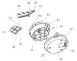
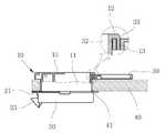
도 1 내지 도 4에서 본 발명 한 실시예의 손잡이는 도어(40)의 앞뒤 양측으로 구비되는 전면부재(10) 및 후면부재(20)로 양분된다. 상기 전면부재(10)는 원형의 몸통(11)이 상기 도어(40)에 천공된 관통구멍(41)으로 끼워지며, 상기 후면부재(20)는 상기 몸통(11) 내부에 구비된 다수의 나사기둥(14)과 대응되는 체결구멍(22)을 통하여 나사못이 나사기둥(14) 내부로 체결되는 과정에서 상기 후면부재(20)가 전면부재(10)에 체결되고, 이때 전면부재(10) 선단의 전면테두리가 도어(40)의 전면에 밀착되고, 후면부재(20) 후단의 후면테두리(21)가 도어(40)의 후면에 밀착되면서 이들 전,후면부재(10)(20)가 도어(40)의 전후면에 고정된다.1 to 4, the handle of the embodiment of the present invention is divided into a
상기 전면테두리는 상기 몸통(11)의 선단에서 도어(40)의 전면과 나란하게 외향으로 돌출되는 수평부(12) 및 상기 수평부(12)에서 직각으로 꺾여서 상기 도어(40)의 전면과 밀착되는 수직부(13)로 구성된다. 상기 수직부(13)는 상기 몸통(11)의 외주면에서 떨어져 구비되고, 상기 수직부(13)의 끝단이 상기 도어(40)의 전면과 닿은 상태로 상기 전면부재(10)가 상기 후면부재(20)와 체결된다.The front edge has a
상기 전면부재(10)의 전면테두리에는 이름표부착판(30) 또는 번호표부착판(31)이 착탈식으로 체결되는데, 상기 이름표부착판(30) 또는 번호표부착판(31)에는 상기 몸통(11)의 외주면에 밀착되는 원호형의 밀착부(32)가 구비된다.The
상기 수직부(13)는 원형의 몸통(11)을 감싸는 원형으로 구성되고 상기 몸통(11) 외주면과의 사이에 틈새가 벌어지는데, 이 틈새로 상기 이름표부착판(30) 또는 번호표부착판(31)의 밀착부(32)가 끼워지도록 상기 이름표부착판(30) 또는 번호표부착판(31)에는 상기 수직부(13)로 들어가는 테두리홈(33)이 상기 밀착부(32) 근방에 구비된다. 상기 테두리홈(33)은 원형의 수직부(13)와 동일하게 원호형으로 구성되며, 상기 테두리홈(33)의 중간부분에는 걸림돌기(34)가 구비된다. 그리고 상기 수직부(13)에는 상기 걸림돌기(34)가 끼워지는 걸림홈(13a)이 구비되어서 상기 테두리홈(33)이 수직부(13)에 끼워진 상태에서 원호 방향으로 회전되는 것을 막는다.The
미설명부호 15는 전면부재(10)의 몸통(11) 내부에 마련된 레버, 23은 상기 레버(15)에 의해 왕복되면서 도어(40)를 사물함에 잠금시키는 슬라이더 이다.
이처럼 구성된 본 발명 한 실시예의 손잡이는 전면부재(10)를 도어(40)의 관통구멍(41)으로 끼우기 전에 이름표부착판(30) 또는 번호표부착판(31)을 전면테두리에 결합시킨다. 이름표부착판(30)은 가로방향으로 길게 형성된 것이고, 번호표부착판(31)은 원형으로 형성되어서 서로 형상이 다르다. 종래에는 이름표 또는 번호표를 전면부재에 일체형으로 형성하다 보니 전면부재의 금형이 두벌 필요하였다.The handle of the embodiment of the present invention thus configured couples the name
본 발명은 하나의 금형으로 전면부재(10)를 사출한 뒤 전면부재(10)의 전면테두리에 별도로 사출된 이름표부착판(30) 또는 번호표부착판(31)을 착탈식으로 조립하면 되므로 이들이 일체로 형성될 때보다 전면부재(10)의 금형부피를 줄일 수 있으므로 경제적이다.Since the
도 2에서 이름표부착판(30)의 밀착부(32)가 몸통(11)에 밀착되도록 테두리홈(33)을 전면부재(10)의 수직부(13)에 끼우되 테두리홈(33)의 걸림돌기(34)가 수직부(13)의 걸림홈(13a)으로 들어가도록 하면 조립된 상태에서 원호방향으로 회전되는 것을 막을 수 있다. 이런 상태로 전면부재(10)의 몸통(11)을 도어(40)의 관통구멍(41)으로 끼우고 도어(40)의 후방에서 후면부재(20)를 전면부재(10)에 체결하면 전면부재(10)의 수직부(13) 끝단이 도어(40)의 표면에 밀착되고, 후면부재(20)의 후면테두리(21)가 도어(40)의 뒷면에 밀착되면서 전,후면부재(20)()가 도어(40)에 결합된다. 이때 수평부(12)의 내면은 밀착부(32)의 표면을 눌러서 이름표부착판(30)이 도어(40)에 고정되도록 해준다.2, the
도 3에서 번호표부착판(31)은 상기 도 2의 이름표부착판(30)과 동일한 방법으로 전면부재(10)에 체결된다. 즉 번호표부착판(31)의 테두리홈(33)이 전면부재(10)의 수직부(13)에 끼워지고 이때 걸림돌기(34)가 걸림홈(13a)으로 들어가서 원호방향의 회전이 억제된다. 이후 전면부재(10)를 도어(40)에 체결하는 과정에서 수직부(13)의 끝단이 도어(40)의 표면에 밀착되고, 수평부(12)의 내면이 밀착부(32)의 표면을 눌러서 번호표부착판(31)이 도어(40)에 고정된다.3, the number
10 : 전면부재 11 : 몸통
12 : 수평부 13 : 수직부
13a : 걸림홈 14 : 나사기둥
20 : 후면부재 30 : 이름표부착판
31 : 번호표부착판 32 : 밀착부
33 : 테두리홈 34 : 걸림돌기
40 : 도어10: front member 11: body
12: horizontal part 13: vertical part
13a: Locking groove 14: Screw column
20: rear member 30: nameplate
31: Number plate attachment plate 32:
33: rim groove 34:
40: Door
Claims (2)
Translated fromKorean상기 전면테두리는 상기 전면부재의 몸통에서 외향으로 벌어지는 수평부; 상기 수평부에서 직각으로 꺾여서 끝단이 상기 도어의 표면에 밀착되고 상기 몸통의 외주면과 떨어져서 동심상으로 원형을 이루는 수직부로 구성되고;
상기 이름표부착판 또는 번호표부착판에는 상기 몸통의 외주면과 접하는 밀착부가 원호상으로 구성되고, 상기 밀착부에는 상기 수직부로 끼워지는 테두리홈이 구비되어서 상기 전면부재가 상기 도어에 체결되는 과정에서 상기 수평부가 상기 밀착부의 표면을 눌러 상기 이름표부착판 또는 번호표부착판이 고정되도록 한 것을 특징으로 하는 표시부를 교체할 수 있는 사물함 손잡이.A front member having a circular body fitted into the through hole of the door, and a front member having a front edge which is in close contact with the front surface of the door; A handle is formed by a rear member which is fastened to the body of the front member at a rear surface of the door; Wherein the front member is provided with a lever to be pulled by a finger, and the rear member is provided with a slider which is locked in a locker in a process of reciprocating with the lever; And a display unit having a nameplate or a number plate attached to the front edge of the handle,
Wherein the front edge extends horizontally outwardly from the body of the front member; And a vertical portion bent at a right angle in the horizontal portion and closely contacting the surface of the door and having a circular shape concentric with the outer peripheral surface of the body;
Wherein the tightening portion is provided with an edge groove that is fitted to the vertical portion so that when the front member is fastened to the door, Wherein the name plate attachment plate or the number plate attachment plate is fixed by pressing the surface of the adhered portion.
상기 전면부재의 수직부에는 걸림홈이 구비되고,
상기 이름표부착판 또는 번호표부착판의 테두리홈에는 상기 걸림홈에 걸려서 원호방향으로 회전이 억제되는 걸림돌기가 구비됨을 특징으로 하는 표시부를 교체할 수 있는 사물함 손잡이.The method according to claim 1,
The vertical member of the front member is provided with an engagement groove,
Wherein the frame groove of the name tag attaching plate or the number tag attaching plate is provided with a latching protrusion which is engaged with the latching groove and is prevented from rotating in a circular arc direction.
Priority Applications (1)
| Application Number | Priority Date | Filing Date | Title |
|---|---|---|---|
| KR1020180073648AKR101963647B1 (en) | 2018-06-26 | 2018-06-26 | Locker handle to replace the display |
Applications Claiming Priority (1)
| Application Number | Priority Date | Filing Date | Title |
|---|---|---|---|
| KR1020180073648AKR101963647B1 (en) | 2018-06-26 | 2018-06-26 | Locker handle to replace the display |
Publications (1)
| Publication Number | Publication Date |
|---|---|
| KR101963647B1true KR101963647B1 (en) | 2019-07-31 |
Family
ID=67473839
Family Applications (1)
| Application Number | Title | Priority Date | Filing Date |
|---|---|---|---|
| KR1020180073648AActiveKR101963647B1 (en) | 2018-06-26 | 2018-06-26 | Locker handle to replace the display |
Country Status (1)
| Country | Link |
|---|---|
| KR (1) | KR101963647B1 (en) |
Cited By (3)
| Publication number | Priority date | Publication date | Assignee | Title |
|---|---|---|---|---|
| KR102270931B1 (en) | 2020-05-19 | 2021-06-30 | (주)퍼맥스 | dial type number indicator |
| KR20230009634A (en)* | 2021-07-09 | 2023-01-17 | 김두철 | The locker sterilizer |
| KR102691456B1 (en)* | 2023-01-18 | 2024-08-05 | 코리아알프스(주) | Pull-up Handle Assembly and MCC with the Same |
Citations (2)
| Publication number | Priority date | Publication date | Assignee | Title |
|---|---|---|---|---|
| KR200378742Y1 (en)* | 2004-12-31 | 2005-03-17 | 주식회사 성림교구 | The lock adhered a nameplate |
| KR101476333B1 (en)* | 2014-04-08 | 2014-12-24 | 주식회사 우드메탈 | Locking device |
- 2018
- 2018-06-26KRKR1020180073648Apatent/KR101963647B1/enactiveActive
Patent Citations (2)
| Publication number | Priority date | Publication date | Assignee | Title |
|---|---|---|---|---|
| KR200378742Y1 (en)* | 2004-12-31 | 2005-03-17 | 주식회사 성림교구 | The lock adhered a nameplate |
| KR101476333B1 (en)* | 2014-04-08 | 2014-12-24 | 주식회사 우드메탈 | Locking device |
Cited By (4)
| Publication number | Priority date | Publication date | Assignee | Title |
|---|---|---|---|---|
| KR102270931B1 (en) | 2020-05-19 | 2021-06-30 | (주)퍼맥스 | dial type number indicator |
| KR20230009634A (en)* | 2021-07-09 | 2023-01-17 | 김두철 | The locker sterilizer |
| KR102569248B1 (en) | 2021-07-09 | 2023-08-24 | 김두철 | Locker handle with sterilizer |
| KR102691456B1 (en)* | 2023-01-18 | 2024-08-05 | 코리아알프스(주) | Pull-up Handle Assembly and MCC with the Same |
Similar Documents
| Publication | Publication Date | Title |
|---|---|---|
| KR101963647B1 (en) | Locker handle to replace the display | |
| US9377671B2 (en) | Waterproof housing for camera | |
| US10614971B2 (en) | Sealing device for a human-machine dialogue element | |
| US8763168B2 (en) | Hinge assembly for toilet seat | |
| US20140245568A1 (en) | Door handle assembly, sub-assembly and method of installing same | |
| US10475420B1 (en) | Reconfigurable guitar fabrication method | |
| MX2007009483A (en) | Deadbolt clip / retainer for interior double cylinder sets. | |
| KR20220103001A (en) | Apparatus for fastening of vehicle license plate | |
| JP5829220B2 (en) | Device having a shape frame element and a hinge for pivotally supporting the shape frame element | |
| KR101130653B1 (en) | Captive screw | |
| IT201900020056A1 (en) | MULTISTANDARD HANDLE RECALL DEVICE | |
| KR20160048555A (en) | clamp apparatus for inbody of digital door lock | |
| WO2023005637A1 (en) | Refrigerator | |
| JPS5852704Y2 (en) | Decorative parts mounting device | |
| JPH02136013A (en) | Decorative plate frame for wiring accesories | |
| JPH0441015Y2 (en) | ||
| KR0119985Y1 (en) | Door trim panel fasteners for vehicles | |
| KR960013866B1 (en) | Door parts in washing machine for crockery | |
| KR101956573B1 (en) | Cassette type mold for resin molding | |
| JPH0239284Y2 (en) | ||
| JPH0542666Y2 (en) | ||
| JPH064986B2 (en) | Vehicle inside handle mounting mechanism | |
| JP2000045586A (en) | Fixing structure of cylinder lock to car panel | |
| JP2501476Y2 (en) | Seal packing structure for vehicle lighting | |
| JPH0319478Y2 (en) |
Legal Events
| Date | Code | Title | Description |
|---|---|---|---|
| PA0109 | Patent application | Patent event code:PA01091R01D Comment text:Patent Application Patent event date:20180626 | |
| PA0201 | Request for examination | ||
| PE0701 | Decision of registration | Patent event code:PE07011S01D Comment text:Decision to Grant Registration Patent event date:20190321 | |
| PR0701 | Registration of establishment | Comment text:Registration of Establishment Patent event date:20190325 Patent event code:PR07011E01D | |
| PR1002 | Payment of registration fee | Payment date:20190325 End annual number:3 Start annual number:1 | |
| PG1601 | Publication of registration | ||
| PR1001 | Payment of annual fee | Payment date:20220419 Start annual number:4 End annual number:4 | |
| PR1001 | Payment of annual fee | Payment date:20230808 Start annual number:5 End annual number:5 | |
| PR1001 | Payment of annual fee | Payment date:20240122 Start annual number:6 End annual number:6 |