KR101962413B1 - Beer brewing machine and beer brewing method using the same - Google Patents
Beer brewing machine and beer brewing method using the sameDownload PDFInfo
- Publication number
- KR101962413B1 KR101962413B1KR1020170119866AKR20170119866AKR101962413B1KR 101962413 B1KR101962413 B1KR 101962413B1KR 1020170119866 AKR1020170119866 AKR 1020170119866AKR 20170119866 AKR20170119866 AKR 20170119866AKR 101962413 B1KR101962413 B1KR 101962413B1
- Authority
- KR
- South Korea
- Prior art keywords
- flow path
- filter
- keg
- coupler
- wort
- Prior art date
- Legal status (The legal status is an assumption and is not a legal conclusion. Google has not performed a legal analysis and makes no representation as to the accuracy of the status listed.)
- Active
Links
- 235000013405beerNutrition0.000titleclaimsabstractdescription160
- 238000000034methodMethods0.000titleclaimsdescription59
- 240000004808Saccharomyces cerevisiaeSpecies0.000claimsabstractdescription118
- 238000004519manufacturing processMethods0.000claimsabstractdescription116
- 238000000855fermentationMethods0.000claimsdescription180
- 230000004151fermentationEffects0.000claimsdescription180
- 230000001954sterilising effectEffects0.000claimsdescription128
- 238000004140cleaningMethods0.000claimsdescription75
- 238000001802infusionMethods0.000claimsdescription66
- XLYOFNOQVPJJNP-UHFFFAOYSA-NwaterSubstancesOXLYOFNOQVPJJNP-UHFFFAOYSA-N0.000claimsdescription46
- 235000011389fruit/vegetable juiceNutrition0.000claimsdescription35
- 238000007599dischargingMethods0.000claimsdescription32
- 239000002699waste materialSubstances0.000claimsdescription29
- 239000000463materialSubstances0.000claimsdescription23
- 238000005406washingMethods0.000claimsdescription23
- 239000002351wastewaterSubstances0.000claimsdescription19
- 230000008878couplingEffects0.000claimsdescription16
- 238000010168coupling processMethods0.000claimsdescription16
- 238000005859coupling reactionMethods0.000claimsdescription16
- 238000004659sterilization and disinfectionMethods0.000claimsdescription13
- 239000000796flavoring agentSubstances0.000claimsdescription11
- 235000019634flavorsNutrition0.000claimsdescription11
- 230000008569processEffects0.000claimsdescription8
- 238000011084recoveryMethods0.000claimsdescription5
- 241000555745SciuridaeSpecies0.000claimsdescription3
- 239000007789gasSubstances0.000description121
- 230000005484gravityEffects0.000description83
- 239000002775capsuleSubstances0.000description60
- 230000008859changeEffects0.000description52
- 238000007789sealingMethods0.000description45
- 238000005259measurementMethods0.000description30
- 238000010586diagramMethods0.000description12
- 238000003860storageMethods0.000description11
- 244000144977poultrySpecies0.000description10
- 101100453790Drosophila melanogaster Kebab geneProteins0.000description9
- 244000046052Phaseolus vulgarisSpecies0.000description9
- 235000010627Phaseolus vulgarisNutrition0.000description9
- 235000015231kebabNutrition0.000description9
- 238000001816coolingMethods0.000description8
- 238000003825pressingMethods0.000description7
- 238000000691measurement methodMethods0.000description6
- 230000032683agingEffects0.000description5
- 230000007423decreaseEffects0.000description4
- BVKZGUZCCUSVTD-UHFFFAOYSA-LCarbonateChemical compound[O-]C([O-])=OBVKZGUZCCUSVTD-UHFFFAOYSA-L0.000description3
- 238000011109contaminationMethods0.000description3
- 230000003247decreasing effectEffects0.000description3
- 238000007654immersionMethods0.000description3
- 239000005445natural materialSubstances0.000description3
- LFQSCWFLJHTTHZ-UHFFFAOYSA-NEthanolChemical compoundCCOLFQSCWFLJHTTHZ-UHFFFAOYSA-N0.000description2
- 230000002159abnormal effectEffects0.000description2
- 230000005856abnormalityEffects0.000description2
- 230000000694effectsEffects0.000description2
- 230000007257malfunctionEffects0.000description2
- 238000012986modificationMethods0.000description2
- 230000004048modificationEffects0.000description2
- 235000012431wafersNutrition0.000description2
- 241000894006BacteriaSpecies0.000description1
- FGUUSXIOTUKUDN-IBGZPJMESA-NC1(=CC=CC=C1)N1C2=C(NC([C@H](C1)NC=1OC(=NN=1)C1=CC=CC=C1)=O)C=CC=C2Chemical compoundC1(=CC=CC=C1)N1C2=C(NC([C@H](C1)NC=1OC(=NN=1)C1=CC=CC=C1)=O)C=CC=C2FGUUSXIOTUKUDN-IBGZPJMESA-N0.000description1
- 240000005979Hordeum vulgareSpecies0.000description1
- 235000007340Hordeum vulgareNutrition0.000description1
- 235000008694Humulus lupulusNutrition0.000description1
- 241000257303HymenopteraSpecies0.000description1
- GXCLVBGFBYZDAG-UHFFFAOYSA-NN-[2-(1H-indol-3-yl)ethyl]-N-methylprop-2-en-1-amineChemical compoundCN(CCC1=CNC2=C1C=CC=C2)CC=CGXCLVBGFBYZDAG-UHFFFAOYSA-N0.000description1
- 229920002472StarchPolymers0.000description1
- 235000009499Vanilla fragransNutrition0.000description1
- 244000263375Vanilla tahitensisSpecies0.000description1
- 235000012036Vanilla tahitensisNutrition0.000description1
- 238000009825accumulationMethods0.000description1
- QVGXLLKOCUKJST-UHFFFAOYSA-Natomic oxygenChemical compound[O]QVGXLLKOCUKJST-UHFFFAOYSA-N0.000description1
- 235000013361beverageNutrition0.000description1
- 238000009835boilingMethods0.000description1
- 238000003795desorptionMethods0.000description1
- 230000006866deteriorationEffects0.000description1
- 239000003205fragranceSubstances0.000description1
- 239000004615ingredientSubstances0.000description1
- 239000002184metalSubstances0.000description1
- 244000005700microbiomeSpecies0.000description1
- 230000001151other effectEffects0.000description1
- 239000001301oxygenSubstances0.000description1
- 229910052760oxygenInorganic materials0.000description1
- 108090000623proteins and genesProteins0.000description1
- 102000004169proteins and genesHuman genes0.000description1
- 238000005086pumpingMethods0.000description1
- 238000010926purgeMethods0.000description1
- 239000003507refrigerantSubstances0.000description1
- 230000004044responseEffects0.000description1
- 238000005070samplingMethods0.000description1
- 239000013049sedimentSubstances0.000description1
- 238000000926separation methodMethods0.000description1
- 235000019698starchNutrition0.000description1
- 239000008107starchSubstances0.000description1
- 238000006467substitution reactionMethods0.000description1
- 238000012546transferMethods0.000description1
- 239000002023woodSubstances0.000description1
Images


Classifications
- C—CHEMISTRY; METALLURGY
- C12—BIOCHEMISTRY; BEER; SPIRITS; WINE; VINEGAR; MICROBIOLOGY; ENZYMOLOGY; MUTATION OR GENETIC ENGINEERING
- C12C—BEER; PREPARATION OF BEER BY FERMENTATION; PREPARATION OF MALT FOR MAKING BEER; PREPARATION OF HOPS FOR MAKING BEER
- C12C11/00—Fermentation processes for beer
- C12C11/003—Fermentation of beerwort
- C12C11/006—Fermentation tanks therefor
- C—CHEMISTRY; METALLURGY
- C12—BIOCHEMISTRY; BEER; SPIRITS; WINE; VINEGAR; MICROBIOLOGY; ENZYMOLOGY; MUTATION OR GENETIC ENGINEERING
- C12C—BEER; PREPARATION OF BEER BY FERMENTATION; PREPARATION OF MALT FOR MAKING BEER; PREPARATION OF HOPS FOR MAKING BEER
- C12C11/00—Fermentation processes for beer
- C—CHEMISTRY; METALLURGY
- C12—BIOCHEMISTRY; BEER; SPIRITS; WINE; VINEGAR; MICROBIOLOGY; ENZYMOLOGY; MUTATION OR GENETIC ENGINEERING
- C12C—BEER; PREPARATION OF BEER BY FERMENTATION; PREPARATION OF MALT FOR MAKING BEER; PREPARATION OF HOPS FOR MAKING BEER
- C12C5/00—Other raw materials for the preparation of beer
- C12C5/02—Additives for beer
- C12C5/026—Beer flavouring preparations
- C—CHEMISTRY; METALLURGY
- C12—BIOCHEMISTRY; BEER; SPIRITS; WINE; VINEGAR; MICROBIOLOGY; ENZYMOLOGY; MUTATION OR GENETIC ENGINEERING
- C12H—PASTEURISATION, STERILISATION, PRESERVATION, PURIFICATION, CLARIFICATION OR AGEING OF ALCOHOLIC BEVERAGES; METHODS FOR ALTERING THE ALCOHOL CONTENT OF FERMENTED SOLUTIONS OR ALCOHOLIC BEVERAGES
- C12H1/00—Pasteurisation, sterilisation, preservation, purification, clarification, or ageing of alcoholic beverages
- C12H1/02—Pasteurisation, sterilisation, preservation, purification, clarification, or ageing of alcoholic beverages combined with removal of precipitate or added materials, e.g. adsorption material
- C12H1/06—Precipitation by physical means, e.g. by irradiation, vibrations
- C12H1/063—Separation by filtration
Landscapes
- Chemical & Material Sciences (AREA)
- Organic Chemistry (AREA)
- Engineering & Computer Science (AREA)
- Health & Medical Sciences (AREA)
- General Health & Medical Sciences (AREA)
- Biochemistry (AREA)
- Bioinformatics & Cheminformatics (AREA)
- General Engineering & Computer Science (AREA)
- Life Sciences & Earth Sciences (AREA)
- Genetics & Genomics (AREA)
- Food Science & Technology (AREA)
- Wood Science & Technology (AREA)
- Zoology (AREA)
- Toxicology (AREA)
- Distillation Of Fermentation Liquor, Processing Of Alcohols, Vinegar And Beer (AREA)
- Devices For Dispensing Beverages (AREA)
Abstract
Translated fromKoreanDescription
Translated fromKorean본 발명은 효모(yeast)가 살아있는 상태의 맥주를 현장에서 전문지식 없이도 직접 생산하여 판매할 수 있으며, 한 번에 다양한 종류의 맥주를 외부와 접촉되어 오염될 여지 없이 자동으로 저비용으로 쉽게 제조 가능한 맥주 제조장치에 관한 것이다.The present invention can directly produce and sell beer in the state where yeast is alive without expert knowledge in the field, and it is possible to produce beer which can be easily manufactured at low cost by automatically contacting various kinds of beer with outside, Manufacturing apparatus.
맥주는 보리를 싹 틔워 만든 맥아로 즙을 만들어 여과한 후에 홉(hop)을 첨가하고 효모로 발효시켜 만든 술이다.The beer is made by fermenting the juice made by sprouting barley with the juice, adding the hop, and fermenting it with the yeast.
이러한 맥주의 제조방법은 맥아를 끓여서 맥즙(wort)를 제조하는 단계와, 맥즙에 효모(yeast)를 공급하여 발효시키는 단계와, 발효된 맥주를 숙성시키는 단계로 이루어지며, 슈퍼나 마트 등에서 판매되는 맥주는 위와 같이 제조된 맥주를 유통 및 보관을 위해 살균처리를 한 후 병이나 캔에 담겨지는 과정을 거치게 된다.The method for producing such a beer comprises the steps of preparing wort by boiling malt, fermenting the wort by supplying yeast to the wort, and aging the fermented beer, The beer is sterilized to distribute and store the beer, and then put in a bottle or a can.
그러나 숙성된 맥주를 살균처리하게 되면 효모가 죽게 되기 때문에, 현재 유통되고 있는 맥주는 살균처리 과정에서 효모가 죽은 상태의 맥주들이다.However, since the yeast is killed by sterilization of aged beer, the beer currently in circulation is a beer in which the yeast is dead during the sterilization process.
반면, 수제 맥주는 효모가 살아있는 상태의 맥주로서, 맥주의 맛과 향을 높이기 위해 직접 생산하는 특색 있는 맥주를 말하는데, 이러한 수제 맥주는 양조 생산 설비가 있는 특별한 곳에서만 맛볼 수 있으며, 어떠한 효모와 홉(hop)을 첨가하느냐에 따라 10만 종 이상의 다양한 종류의 수제 맥주 제조가 가능하다.Handmade beer, on the other hand, refers to a characteristic beer that is produced by a yeast in order to enhance the taste and flavor of the beer. This beer can only be tasted in a special place with brewing equipment, it is possible to manufacture more than 100,000 kinds of handmade beer depending on whether or not the hop is added.
그러나 수제 맥주는 복잡하고 다양한 제조과정을 거쳐야만 가능하며, 특히 발효와 숙성 과정에서 막대한 설비투자와 긴 제조시간, 많은 노동인력 등이 필요하며, 제조 전 과정을 전문인력이 직접 관리해야 하는 비효율적인 제조시스템이다.However, handmade beer can only be processed through complicated and diverse manufacturing processes. In particular, in the process of fermentation and aging, a large amount of equipment investment, a long manufacturing time and a lot of labor manpower are required. Inefficient manufacturing System.
또한, 맥즙 제조 후 발효를 위해서는 맥즙통에 담겨진 맥즙을 발효를 위한 발효통으로 옮겨 담는 공정이 필요하며, 이때 외부 접촉으로 인한 오염 및 산소 접촉으로 인한 맥주 품질 저하가 생길 수 있기 때문에, 발효시 효모 외에 다른 균이 없도록 모든 접촉면과 유로를 세척살균해야 하며, 그에 따라 많은 시간과 노동 인력이 필요하다는 문제가 있다.In addition, in order to ferment after the production of wort, it is necessary to transfer the wort contained in the brewer to the fermentation vessel for fermentation. In this case, since contamination due to external contact and deterioration of beer quality due to oxygen contact may occur, It is necessary to wash and sterilize all the contact surfaces and the flow path so that there is no other bacteria, and thus there is a problem that a lot of time and labor are required.
즉, 종래 수제 맥주 제조를 위해서는 막대한 설비투자와 장비 및 인력을 필요로 하며, 수제 맥주 제조를 소규모로 하고자 할 때에도 수억의 설비투자 및 많은 인력을 고용하여야 하며, 특히 수제 맥주 제조에 관한 전문지식 또는 전문인력이 필요하다는 문제가 있다.In other words, in order to manufacture handmade beer, huge equipment investment, equipment and manpower are required, and even when small-sized handmade beer manufacturing is required, hundreds of millions of facilities investment and a lot of manpower should be hired. In particular, There is a problem that professional manpower is needed.
한편, 종래의 맥주 제조장치는 한 번에 많은 양의 맥즙을 만들어 대용량의 맥주를 하나의 탱크에서 발효하여 생산하였으나, 이러한 공정은 맥주에 약간의 오염이라도 생기면 전체 맥주가 오염되어 쓸 수 없거나 팔리지 않을 때 장기간 보관해야 하기 때문에 맥주의 품질이 떨어지는 문제가 있었다.Meanwhile, in the conventional beer manufacturing apparatus, a large amount of beer was produced by fermenting a large amount of beer in one tank at a time, but such a process would not be able to be used or sold if the beer was slightly contaminated There is a problem that the beer quality is deteriorated because it is required to be stored for a long period of time.
본 발명은 상기와 같은 문제점을 해결하기 위한 것으로서, 효모(yeast)가 살아있는 상태의 맥주를 전문지식 없이도 현장에서 직접 생산하여 판매할 수 있으며, 한 번에 다양한 종류의 맥주를 외부와 접촉되어 오염될 여지 없이 자동으로 저비용으로 쉽게 제조 가능한 맥주 제조장치를 제공함을 목적으로 한다.The present invention has been made to solve the above-mentioned problems, and it is an object of the present invention to provide a method and apparatus for producing and selling beer in a state where a yeast is alive without expert knowledge, And to provide a beer manufacturing apparatus which can be easily and automatically manufactured at low cost without any limitation.
또한, 본 발명은 자동으로 유로부 살균세척과 드라이 호핑 등의 스마트 인퓨징이 가능한 맥주 제조장치와, 이러한 맥주 제조장치를 이용하여 자동으로 유로부 살균세척하고 스마트 인퓨징할 수 있는 맥주 제조방법을 제공함을 목적으로 한다.The present invention also relates to a beer manufacturing apparatus capable of automatically performing fusing such as sterilization cleaning and dry hopping, and a beer manufacturing method capable of automatically cleaning and sterilizing the flow path using the beer manufacturing apparatus The purpose is to provide.
또한, 본 발명은 비접촉 발효도 측정 방법을 이용하여 정밀한 제어가 가능한 맥주 제조장치와, 이러한 맥주 제조장치의 제어방법을 제공함을 목적으로 한다.It is another object of the present invention to provide a beer making apparatus capable of precisely controlling the non-contact fermentation degree measuring method and a control method of the beer making apparatus.
또한, 본 발명은 효모캡슐이 일체화된 케그캡과, 상기 케그캡에 결합하는 커플러를 제공함을 목적으로 한다.It is another object of the present invention to provide a kebab cap in which yeast capsules are integrated and a coupler to be coupled to the kebab cap.
본 발명의 일실시 예에 따른 맥주 제조장치는, 챔버; 상기 챔버 내에 고정설치되며, 맥즙유로와 가스유로가 구비되는 커플러; 상기 커플러의 맥즙유로와 가스유로를 연결하는 유로부; 상기 커플러에 결합하여 상기 유로부가 폐유로가 되도록 하는 살균세척용 마개; 상기 유로부에 연결되며, 내부에 살균세척수가 담긴 살균세척용 필터용기; 상기 유로부에 연결되는 펌프; 및 상기 살균세척용 필터용기에 담긴 살균세척수가 상기 폐유로가 된 유로부를 순환하도록 상기 펌프의 작동을 제어하는 제어부;를 포함할 수 있다.A beer manufacturing apparatus according to an embodiment of the present invention includes a chamber; A coupler fixedly installed in the chamber and having a wick flow path and a gas flow path; A channel portion connecting the wick channel and the gas channel of the coupler; A sterilizing cleaning plug coupled to the coupler to allow the flow path portion to become waste oil; A sterilizing cleaning filter container connected to the flow path portion and containing sterilizing washing water therein; A pump connected to the flow path portion; And a controller for controlling the operation of the pump so that the sterilizing wash water contained in the filter container for sterilizing washing circulates through the flow path portion where the waste oil flows.
또한, 본 발명의 일실시 예에 따른 맥주 제조장치는, 상기 유로부는, 상기 커플러의 가스유로와 상기 펌프를 연결하는 제1 유로; 상기 커플러의 맥즙유로와 상기 펌프를 연결하는 제2 유로; 상기 제1 유로에 구비되는 가스배출부; 상기 가스배출부를 개폐시키는 제1 밸브; 및 상기 가스배출부와 상기 펌프 사이에 구비되어 상기 제1 유로를 개폐시키는 제2 밸브;를 포함하고, 상기 살균세척용 필터용기는 상기 제2 유로에 연결될 수 있다.According to another aspect of the present invention, there is provided a beer manufacturing apparatus, wherein the flow path portion includes: a first flow path connecting the gas flow path of the coupler and the pump; A second flow path connecting the pump flow path of the coupler and the pump; A gas outlet provided in the first flow path; A first valve for opening and closing the gas discharge portion; And a second valve disposed between the gas discharge unit and the pump for opening and closing the first flow path, and the filter container for sterilizing cleaning may be connected to the second flow path.
또한, 본 발명의 일실시 예에 따른 맥주 제조장치는, 상기 챔버에는 상기 제2 유로에 연결된 상태로 고정설치되되 상기 살균세척용 필터용기의 필터캡이 결합하는 경우에 상기 살균세척용 필터용기 내부와 상기 제2 유로를 연결하는 필터헤드가 구비되고, 상기 필터헤드에는 상기 커플러의 맥즙유로에 연결되는 제1 필터유로와, 상기 펌프에 연결되는 제2 필터유로가 형성되고, 상기 필터캡에는 상기 살균세척용 필터용기 내부 바닥면까지 길게 형성되는 제1 필터호스와, 상기 살균세척용 필터용기 내부 공간에 연결되는 제2 필터호스가 구비되고, 상기 필터캡이 상기 필터헤드에 결합한 경우에, 상기 필터캡의 제1 필터호스는 상기 필터헤드의 제1 필터유로에 연결되고, 상기 필터캡의 제2 필터호스는 상기 필터헤드의 제2 필터유로에 연결될 수 있다.Further, in the beer manufacturing apparatus according to an embodiment of the present invention, when the filter cap of the sterilizing cleaning filter container is coupled to the chamber, the chamber is fixedly connected to the second flow path, Wherein the filter head is provided with a first filter channel connected to the wick channel of the coupler and a second filter channel connected to the pump, And a second filter hose connected to the inner space of the filter container for sterilizing cleaning, wherein when the filter cap is coupled to the filter head, The first filter hose of the filter cap is connected to the first filter channel of the filter head and the second filter hose of the filter cap is connected to the second filter channel of the filter head.
한편, 다른 측면에서의 본 발명의 일실시 예에 따른 맥주 제조장치는, 챔버; 상기 챔버 내에 고정설치되며, 맥즙유로와 가스유로가 구비되는 커플러; 상기 커플러의 맥즙유로와 가스유로를 연결하는 유로부; 상기 커플러에 결합하여 상기 유로부에 연결된 상태로 상기 챔버 내에 장착된 맥즙이 담긴 케그; 상기 유로부에 연결되며, 내부에 상기 케그에 담긴 맥즙에 맛과 향을 우려내기 위한 재료가 담긴 스마트 인퓨징용 필터용기; 상기 유로부에 연결되는 펌프; 및 상기 스마트 인퓨징용 필터용기에 담긴 재료가 상기 케그에 담긴 맥즙에 우려지도록 상기 펌프의 작동을 제어하는 제어부;를 포함할 수 있다.According to another aspect of the present invention, there is provided a beer manufacturing apparatus comprising: a chamber; A coupler fixedly installed in the chamber and having a wick flow path and a gas flow path; A channel portion connecting the wick channel and the gas channel of the coupler; A keg containing wastes mounted in the chamber coupled to the coupler and connected to the channel portion; A smart infusion filter container which is connected to the flow path and contains therein a material for causing taste and aroma to the wort contained in the keg; A pump connected to the flow path portion; And a control unit for controlling the operation of the pump so that the material contained in the filter unit for smart infusion may be worsened by the juice contained in the keg.
또한, 본 발명의 일실시 예에 따른 맥주 제조장치는, 상기 제어부는 상기 케그에 담긴 맥즙이 상기 유로부를 순환하도록 상기 펌프의 작동을 제어할 수 있다.Further, in the beer manufacturing apparatus according to an embodiment of the present invention, the control unit may control the operation of the pump so that the wort contained in the keg circulates through the flow path portion.
또한, 본 발명의 일실시 예에 따른 맥주 제조장치는, 상기 제어부는 상기 케그에 담긴 맥즙이 상기 스마트 인퓨징용 필터용기 내부에 소정시간 동안 침지되었다가 다시 상기 케그로 회수되는 과정이 반복적으로 일어나도록 상기 펌프의 작동을 제어할 수 있다.Further, in the beer manufacturing apparatus according to an embodiment of the present invention, the control unit repeatedly performs a process in which the wort contained in the keg is immersed in the smart infusion filter container for a predetermined period of time, The operation of the pump can be controlled.
또한, 본 발명의 일실시 예에 따른 맥주 제조장치는, 상기 유로부는, 상기 커플러의 가스유로와 상기 펌프를 연결하는 제1 유로; 상기 커플러의 맥즙유로와 상기 펌프를 연결하는 제2 유로; 상기 제1 유로에 구비되는 가스배출부; 상기 가스배출부를 개폐시키는 제1 밸브; 및 상기 가스배출부와 상기 펌프 사이에 구비되어 상기 제1 유로를 개폐시키는 제2 밸브;를 포함하고, 상기 스마트 인퓨징용 필터용기는 상기 제2 유로에 연결될 수 있다.According to another aspect of the present invention, there is provided a beer manufacturing apparatus, wherein the flow path portion includes: a first flow path connecting the gas flow path of the coupler and the pump; A second flow path connecting the pump flow path of the coupler and the pump; A gas outlet provided in the first flow path; A first valve for opening and closing the gas discharge portion; And a second valve disposed between the gas discharge unit and the pump for opening and closing the first flow path, wherein the smart infusion filter can be connected to the second flow path.
또한, 본 발명의 일실시 예에 따른 맥주 제조장치는, 상기 스마트 인퓨징용 필터용기와 상기 펌프 사이에는 수위센서가 구비될 수 있다.Further, in the beer manufacturing apparatus according to an embodiment of the present invention, a water level sensor may be provided between the smart infusion filter container and the pump.
또한, 본 발명의 일실시 예에 따른 맥주 제조장치는, 상기 케그에는 내부를 밀폐시키며, 상기 커플러에 결합하여 상기 케그 내부를 상기 유로부에 연결시키는 케그캡이 구비되고, 상기 케그캡에는 상기 케그 내부 바닥면까지 길게 형성되는 맥즙호스와, 상기 케그 내부 공간과 연결되는 가스배출유로가 구비되고, 상기 케그캡이 상기 커플러에 결합한 경우에, 상기 케그캡의 맥즙호스는 상기 커플러의 맥즙유로에 연결되고, 상기 케그캡의 가스배출유로는 상기 커플러의 가스유로에 연결될 수 있다.Further, the beer manufacturing apparatus according to an embodiment of the present invention is characterized in that the keeg is provided with a keel cap which hermetically closes the inside of the keel and connects the inside of the keg to the coupler, And a gas discharging passage connected to the inner space of the keg. When the cap cap is coupled to the coupler, the wick hose of the cap cap is connected to the wastewater passage of the coupler And the gas discharge passage of the cap cap may be connected to the gas passage of the coupler.
또한, 본 발명의 일실시 예에 따른 맥주 제조장치는, 상기 챔버에는 상기 제2 유로에 연결된 상태로 고정설치되되 상기 스마트 인퓨징용 필터용기의 필터캡이 결합하는 경우에 상기 스마트 인퓨징용 필터용기 내부와 상기 제2 유로를 연결하는 필터헤드가 구비되고, 상기 필터헤드에는 상기 커플러의 맥즙유로에 연결되는 제1 필터유로와, 상기 펌프에 연결되는 제2 필터유로가 형성되고, 상기 필터캡에는 상기 필터용기 내부 바닥면까지 길게 형성되는 제1 필터호스와, 상기 필터용기 내부 공간에 연결되는 제2 필터호스가 구비되고, 상기 필터캡이 상기 필터헤드에 결합한 경우에, 상기 필터캡의 제1 필터호스는 상기 필터헤드의 제1 필터유로에 연결되고, 상기 필터캡의 제2 필터호스는 상기 필터헤드의 제2 필터유로에 연결될 수 있다.Further, in the beer manufacturing apparatus according to an embodiment of the present invention, when the filter cap of the smart infusion filter container is coupled to the chamber, the chamber is fixedly connected to the second flow path, Wherein the filter head is provided with a first filter channel connected to the wick channel of the coupler and a second filter channel connected to the pump, A first filter hose extending to the bottom of the filter container and a second filter hose connected to the space inside the filter container, wherein when the filter cap is coupled to the filter head, The hose is connected to the first filter passage of the filter head and the second filter hose of the filter cap can be connected to the second filter passage of the filter head.
한편, 본 발명의 일실시 예에 따른 맥주 제조방법은, 챔버 내에 고정설치된 커플러의 맥즙유로와 가스유로를 연결하는 유로부를 살균세척하는 유로부 살균세척 단계; 맥즙이 담긴 케그의 케그캡을 상기 커플러에 결합하여 상기 맥즙이 담긴 케그의 내부를 상기 살균세척된 유로부에 연결하는 케그 장착 단계; 상기 챔버 내에 장착된 케그에 담긴 맥즙을 발효시키기 위한 효모를 공급하는 효모 공급 단계; 상기 유로부에 구비된 가스배출부를 열어 상기 케그에 담긴 맥즙 발효시 발생하는 가스를 외부로 배출시키는 1차 발효 단계; 및 상기 가스배출부를 닫아 상기 케그에 담긴 맥즙 발효시 발생하는 가스를 이용하여 상기 1차 발효된 맥즙을 자연 탄산화시키는 2차 발효 단계;를 포함할 수 있다.According to another aspect of the present invention, there is provided a method of manufacturing a beer, comprising the steps of: sterilizing and cleaning a channel portion connecting a wick channel and a gas channel of a coupler fixedly installed in a chamber; A keg mounting step of coupling a cap casing cap containing the wort to the coupler to connect the interior of the casing containing the wort to the sterilizing and cleaning channel section; A yeast supply step of supplying yeast for fermenting the wort contained in the keg mounted in the chamber; A primary fermentation step of opening the gas discharge part provided in the flow path part and discharging the gas generated during fermentation of the wort contained in the kettle to the outside; And a secondary fermentation step of closing the gas discharging part and naturally carbonating the primary fermented wort using gas generated during fermentation of the wort contained in the kettle.
또한, 본 발명의 일실시 예에 따른 맥주 제조방법은, 상기 유로부 살균세척 단계는, 상기 유로부가 폐유로가 되도록 상기 커플러에 살균세척용 마개를 결합하고, 상기 유로부에 살균세척용 필터용기를 연결하는 살균세척용 마개 결합 및 살균세척용 필터용기 장착 단계; 상기 유로부에 연결된 펌프를 작동시켜 상기 살균세척용 필터용기에 담긴 살균세척수를 소정시간 동안 상기 폐유로가 된 유로부로 순환시키는 살균세척수 순환 단계; 상기 펌프를 반대방향으로 작동시켜 상기 순환하는 살균세척수를 상기 살균세척용 필터용기로 회수하는 살균세척수 회수 단계; 및 상기 커플러에 결합된 살균세척용 마개를 분리하고, 상기 유로부에 연결된 살균세척용 필터용기를 분리하는 살균세척용 마개 분리 및 살균세척용 필터용기 탈착 단계;를 포함할 수 있다.In the method of manufacturing a beer according to an embodiment of the present invention, the sterilizing and cleaning step of the flow path portion may include a sterilizing cleaning stopper coupled to the coupler so that the flow path portion becomes waste oil, A filter container mounting step for sterilizing cleaning plug connecting and sterilizing washing; Circulating a sterilizing washing water circulating the sterilizing washing water contained in the filter container for sterilizing cleaning to the flow path portion for the predetermined time by operating a pump connected to the flow path portion; A sterilizing wash water recovery step of operating the pump in the opposite direction to recover the circulating sterilizing wash water to the sterilizing wash filter container; And a sterilizing cleaning plug detachment and a sterilizing cleaning filter detaching step for separating the sterilizing cleaning plug coupled to the coupler and separating the sterilizing cleaning filter container connected to the flow path portion.
또한, 본 발명의 일실시 예에 따른 맥주 제조방법은, 상기 맥주 제조방법은 상기 케그에 담긴 맥즙에 맛과 향을 우려내는 스마트 인퓨징 단계를 더 포함하고, 상기 스마트 인퓨징 단계는, 상기 유로부에 스마트 인퓨징용 필터용기를 연결하는 스마트 인퓨징용 필터용기 장착 단계와, 상기 유로부에 연결된 펌프를 작동시켜 상기 케그에 담긴 맥즙에 상기 스마트 인퓨징용 필터용기에 담긴 재료를 우려내는 인퓨징 단계를 포함할 수 있다.Further, in the beer manufacturing method according to an embodiment of the present invention, the beer manufacturing method may further include a smart fusing step of influencing flavor and aroma in the wort contained in the keg, A step of mounting a smart infusion filter container for connecting a smart infusion filter container to the smart infusion filter container, and a step of operating the pump connected to the flow path portion to infuse the smart infusion filter container with the wort contained in the smart infusion container, .
또한, 본 발명의 일실시 예에 따른 맥주 제조방법은, 상기 인퓨징 단계는, 상기 펌프를 작동시켜 소정시간 동안 상기 케그에 담긴 맥즙을 상기 유로부로 순환시키는 맥즙 순환 단계와, 상기 펌프를 반대방향으로 작동시켜 상기 순환하는 맥즙을 상기 케그 내부로 회수하는 맥즙 회수 단계를 포함할 수 있다.In the method of manufacturing a beer according to an embodiment of the present invention, the infusing step may include: a wax circulation step of circulating wastes contained in the keg to the flow path portion by operating the pump for a predetermined time; And returning the circulating wort to the inside of the keg.
또한, 본 발명의 일실시 예에 따른 맥주 제조방법은, 상기 인퓨징 단계는, 상기 펌프를 작동시켜 상기 케그에 담긴 맥즙을 상기 스마트 인퓨징용 필터용기로 유입시키는 맥즙 유입 단계와, 상기 스마트 인퓨징용 필터용기 내부에 맥즙이 채워지면 상기 펌프의 작동을 정지시켜 상기 맥즙이 상기 스마트 인퓨징용 필터용기에 담긴 재료에 침지된 상태를 소정시간 동안 유지시키는 맥즙 침지 단계와, 상기 펌프를 반대방향으로 작동시켜 상기 필터용기 내부에 침지된 맥즙을 상기 케그 내부로 회수하는 맥즙 회수 단계를 포함하고, 상기 인퓨징 단계는 상기 맥즙 유입 단계, 상기 맥즙 침지 단계 및 상기 맥즙 회수 단계가 순서대로 반복적으로 이루어질 수 있다.According to another aspect of the present invention, there is provided a method of manufacturing beer according to the present invention, wherein the infusing step comprises: a wick inflow step of operating the pump to infuse wort contained in the keel into the smart infusion filter container; A step of stopping the operation of the pump when the wort is filled in the filter container to hold the wort immersed in the material contained in the smart infusion filter container for a predetermined period of time; And a wort collecting step of collecting the wort immersed in the filter container into the keg. In the infusing step, the wax inflow step, the wax immersion step, and the wort collecting step may be repeated in order.
또한, 본 발명의 일실시 예에 따른 맥주 제조방법은, 상기 인퓨징 단계는 상기 1차 발효 단계 중에 이루어지되, 상기 2차 발효 단계 시작 소정시간 전부터 상기 2차 발효 단계 시작 직전까지 이루어질 수 있다.The method of manufacturing beer according to an embodiment of the present invention may be performed during the first fermentation step but before the start of the second fermentation step from a predetermined time before the second fermentation step.
또한, 본 발명의 일실시 예에 따른 맥주 제조방법은, 상기 2차 발효 단계는 상기 케그 내부 압력이 기 설정된 상한값에 도달하면 상기 가스배출부를 열고, 상기 케그 내부 압력이 기 설정된 하한값에 도달하면 상기 가스배출부를 닫음으로써, 상기 발효되는 맥즙의 탄산화 정도를 기 설정된 압력범위 내로 유지시킬 수 있다.Further, in the method of manufacturing a beer according to an embodiment of the present invention, the secondary fermentation step may include opening the gas discharging part when the internal pressure of the keg reaches a predetermined upper limit value, and when the internal pressure of the keg reaches a predetermined lower limit value By closing the gas discharging portion, the degree of carbonation of the fermented wort can be maintained within a predetermined pressure range.
상기와 같은 구성을 가지는 본 발명의 일실시 예에 따른 맥주 제조장치 및 제조방법에 의하면, 공장에서 제조되어 제공된 맥즙이 담겨 밀봉된 케그를 챔버에 장착하기만 하면 전문지식 없이도 외부와 접촉되어 오염될 여지 없이 자동으로 쉽게 효모가 살아있는 상태의 맥주를 제조할 수 있다.According to the apparatus and method for manufacturing beer according to one embodiment of the present invention, when a sealed keel containing a wort produced and provided at a factory is mounted in a chamber, It is possible to manufacture beer in a state where the yeast can live easily and automatically.
또한, 본 발명의 일실시 예에 따른 맥주 제조장치 및 제조방법에 의하면, 독립적으로 온도조절이 가능하고 독립적인 발효가 가능한 챔버를 복수개 구비하기 때문에, 한 번에 다양한 종류의 맥주를 제조할 수 있다.According to the apparatus and method for manufacturing beer according to an embodiment of the present invention, since a plurality of chambers capable of independent temperature control and independent fermentation are provided, various types of beer can be manufactured at one time .
또한, 본 발명의 일실시 예에 따른 맥주 제조장치 및 제조방법에 의하면, 하나의 냉각장치를 이용하여 복수의 챔버 각각에 개별적으로 냉기를 공급할 수 있다.In addition, according to the beer manufacturing apparatus and the manufacturing method according to an embodiment of the present invention, it is possible to individually supply cool air to each of the plurality of chambers by using one cooling apparatus.
또한, 본 발명의 일실시 예에 따른 맥주 제조장치 및 제조방법에 의하면, 복수의 챔버가 구비되는 발효실이 회전 가능하게 구비되기 때문에, 사용자가 케그를 복수의 챔버 각각에 장착시키거나 탈착시키기가 편리하다.Further, according to the apparatus and method for manufacturing beer according to an embodiment of the present invention, since the fermentation chamber having a plurality of chambers is rotatably provided, it is convenient for the user to attach or detach the keg to each of the plurality of chambers Do.
또한, 본 발명의 일실시 예에 따른 맥주 제조장치 및 제조방법에 의하면, 챔버에 케그를 장착하기 전에 맥즙을 발효시키기 위한 발효장치의 유로부를 자동으로 살균세척할 수 있으며, 이와 같이 살균세척된 유로부에 케그가 연결된 후에는 외부와 접촉되어 오염될 여지 없이 자동으로 맥주 제조를 완료할 수 있다.In addition, according to the apparatus and method for manufacturing beer according to an embodiment of the present invention, the channel portion of the fermentation apparatus for fermenting the wort can be automatically sterilized and cleaned before mounting the keg in the chamber, After the beaker is connected, it can be contacted with the outside and be able to automatically complete the beer production without being polluted.
또한, 본 발명의 일실시 예에 따른 맥주 제조장치 및 제조방법에 의하면, 케그에 담긴 맥즙 발효시 맥즙에 맛과 향을 우려내기 위한 드라이 호핑 등의 스마트 인퓨징을 외부와 접촉되어 오염될 여지 없이 자동으로 할 수 있다.In addition, according to the apparatus and method for manufacturing beer according to an embodiment of the present invention, smart fusing such as dry hopping for worrying the taste and aroma in the wort during fermentation of the wort in a keel can be contacted with the outside, You can do it automatically.
또한, 본 발명의 일실시 예에 따른 비접촉 발효도 측정 방법을 이용한 맥주 제조장치 및 맥주 제조장치의 제어방법에 의하면, 비접촉 발효도 측정 방법을 이용하여 오염될 여지 없이 맥주 제조장치의 정밀한 제어가 가능하다.Further, according to the beer manufacturing apparatus and the beer manufacturing apparatus control method using the non-contact fermentation measuring method according to an embodiment of the present invention, it is possible to precisely control the beer manufacturing apparatus without being contaminated by using the non-contact fermentation measuring method Do.
또한, 본 발명의 일실시 예에 따른 비접촉 발효도 측정 방법에 의하면, 맥즙이 담긴 케그의 무게변화 측정시 외부의 소음, 진동 등의 외란에 의한 오차를 최소화할 수 있어서, 비접촉 발효도 측정의 정확성을 향상시킬 수 있다.In addition, according to the non-contact fermentation measuring method of the present invention, it is possible to minimize the error due to external disturbance such as noise and vibration when measuring the weight change of the cake containing the wort, Can be improved.
또한, 본 발명의 일실시 예에 따른 효모캡슐이 일체화된 케그캡 및 상기 케그캡에 결합하는 커플러에 의하면, 자동으로 쉽게 효모캡슐에 담긴 효모를 케그에 담긴 맥즙으로 공급할 수 있다.In addition, according to the present invention, the yeast capsules are integrated with the keelcap and the coupler that is coupled to the keelcap, the yeast encapsulated in the yeast capsules can be easily and automatically supplied to the keel contained in the keel.
본 발명에 따른 효과들은 이상에서 언급된 효과들로 제한되지 않으며, 언급되지 않은 또 다른 효과들은 청구범위와 상세한 설명의 기재로부터 본 발명이 속하는 기술분야에서 통상의 지식을 가진자에게 명확하게 이해될 수 있을 것이다.The effects according to the present invention are not limited to the effects mentioned above, and other effects not mentioned can be clearly understood by those skilled in the art from the description of the claims and the detailed description It will be possible.
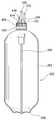
도 1은 본 발명의 일실시 예에 따른 맥주 제조장치를 나타내는 사시도이고,
도 2는 도 1에 따른 맥주 제조장치의 개략적인 수직단면도이고,
도 3은 도 1에 따른 맥주 제조장치의 개략적인 수평단면도이고,
도 4는 본 발명의 일실시 예에 따른 냉기공급장치를 설명하기 위한 도면이고,
도 5는 본 발명의 일실시 예에 따른 발효장치를 설명하기 위한 도면이고,
도 6은 본 발명의 일실시 예에 따른 발효장치의 구성도이고,
도 7은 도 1에 따른 맥주 제조장치의 챔버 내부를 나타내는 도면이고,
도 8은 도 7의 챔버에 케그가 결합된 상태를 나타내는 도면이고,
도 9는 도 7의 챔버에 케그가 결합하여 형성된 독립된 유로부를 개략적으로 나타내는 도면이고,
도 10은 본 발명의 일실시 예에 따른 맥주 제조장치의 구성도이고,
도 11은 본 발명의 일실시 예에 따른 맥주 제조장치를 이용한 맥주 제조방법을 나타내는 흐름도이고,
도 12 내지 도 14는 본 발명의 일실시 예에 따른 맥주 제조장치를 이용한 유로부 살균세척 단계를 설명하기 위한 도면들로서, 도 12는 커플러에 살균세척용 마개를 결합한 상태를 개략적으로 나타내는 도면이고, 도 13은 살균세척수가 유로부를 순환하는 상태를 개략적으로 나타내는 도면이고, 도 14는 본 발명의 일실시 예에 따른 유로부의 살균세척 방법을 나타내는 흐름도이고,
도 15 내지 도 18은 본 발명의 일실시 예에 따른 맥주 제조장치를 이용한 스마트 인퓨징 단계를 설명하기 위한 도면들로서, 도 15는 커플러에 맥즙이 담긴 케그를 결합한 상태를 개략적으로 나타내는 도면이고, 도 16은 케그에 담긴 맥즙이 유로부를 순환하는 상태를 개략적으로 나타내는 도면이고, 도 17은 본 발명의 일실시 예에 따른 스마트 인퓨징 단계를 나타내는 흐름도이고, 도 18은 본 발명의 다른 실시 예에 따른 스마트 인퓨징 단계를 나타내는 흐름도이고,
도 19는 본 발명의 일실시 예에 따른 비접촉식 발효도 측정 방법을 이용한 맥주 제조장치를 나타내는 구성도이고,
도 20은 맥즙의 발효진행 시간에 따른 비중감소를 나타내는 발효곡선이고,
도 21은 본 발명의 일실시 예에 따른 발효도 측정부를 나타내는 구성도이고,
도 22는 본 발명의 일실시 예에 따른 비접촉 발효도 측정방법을 나타내는 흐름도이고,
도 23은 저장된 무게변화 측정값들을 기록하여 발효곡선을 추정하고, 상기 추정된 발효곡선으로부터 외란에 의해 상기 무게변화 측정값이 없는 시간대에서의 상기 무게변화 측정값을 보상한 값들을 나타내는 도표이고,
도 24 내지 도 32는 본 발명의 일실시 예에 따른 맥주 제조장치를 설명하기 위한 도면들로서, 도 24는 본 발명의 일실시 예에 따른 맥주 제조장치에 제공되는 맥즙이 담긴 케그를 나타내는 도면이고, 도 25는 도 24에 따른 맥즙이 담긴 케그의 분해사시도 이고, 도 26은 도 24에 따른 맥즙이 담긴 케그의 케그캡에 커플러가 결합된 상태를 나타내는 도면이고, 도 27은 본 발명의 일실시 예에 따른 효모캡슐 일체형 케그캡의 개략적인 단면도이고, 도 28은 도 27에 따른 케그캡에 결합하는 커플러의 개략적인 단면도이고, 도 29는 도 27에 따른 케그캡과 도 28에 따른 커플러가 결합한 상태의 개략적인 단면도이고, 도 30은 도 29의 'A' 부분 확대도이고, 도 31은 도 29의 'B' 부분 확대도이고, 도 32는 도 29의 'C' 부분 확대도이다.1 is a perspective view showing a beer manufacturing apparatus according to an embodiment of the present invention,
Fig. 2 is a schematic vertical sectional view of the beer manufacturing apparatus according to Fig. 1,
3 is a schematic horizontal cross-sectional view of the beer manufacturing apparatus according to Fig. 1,
4 is a view for explaining a cool air supply device according to an embodiment of the present invention,
5 is a view for explaining a fermentation apparatus according to an embodiment of the present invention,
6 is a configuration diagram of a fermentation apparatus according to an embodiment of the present invention,
7 is a view showing the interior of the chamber of the beer manufacturing apparatus shown in Fig. 1,
Fig. 8 is a view showing a state where the chamber is coupled to the chamber of Fig. 7,
FIG. 9 is a view schematically showing an independent flow path formed by coupling the chamber of FIG. 7,
10 is a configuration diagram of a beer manufacturing apparatus according to an embodiment of the present invention,
11 is a flowchart illustrating a beer manufacturing method using a beer manufacturing apparatus according to an embodiment of the present invention,
12 to 14 are diagrams for explaining the steps of cleaning the path portion disinfection using the beer manufacturing apparatus according to an embodiment of the present invention, and FIG. 12 is a view schematically showing a state in which a sterilizing cleaning stopper is coupled to a coupler, FIG. 13 is a view schematically showing a state in which sterilizing wash water circulates through the flow path portion, FIG. 14 is a flowchart showing a sterilizing cleaning method of the flow path portion according to an embodiment of the present invention,
15 to 18 are diagrams for explaining a smart infusing step using a beer making apparatus according to an embodiment of the present invention, and FIG. 15 is a view schematically showing a state where a coupler is coupled with a cake containing wort, Fig. 17 is a flow chart showing a smart fusing step according to an embodiment of the present invention, and Fig. 18 is a flowchart illustrating a smart fusing step according to another embodiment of the present invention Figure 6 is a flow chart illustrating the smart fusing step,
FIG. 19 is a view showing a beer manufacturing apparatus using a non-contact fermentation measurement method according to an embodiment of the present invention,
20 is a fermentation curve showing the decrease in specific gravity with time of fermentation of wort,
FIG. 21 is a configuration diagram showing a fermentation degree measuring unit according to an embodiment of the present invention,
22 is a flowchart showing a non-contact fermentation measurement method according to an embodiment of the present invention,
23 is a table showing the values obtained by recording the stored weight change measurement values and estimating the fermentation curve and compensating the measured weight change values at the time of the absence of the weight change measurement value by the disturbance from the estimated fermentation curve,
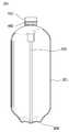
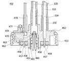
24 to 32 are diagrams for explaining a beer manufacturing apparatus according to an embodiment of the present invention, FIG. 24 is a view showing a cake containing bean juice provided in the beer manufacturing apparatus according to an embodiment of the present invention, FIG. 25 is an exploded perspective view of the cake containing the bean juice according to FIG. 24, FIG. 26 is a view showing a state where the coupler is coupled to the bean cake cap containing the bean juice according to FIG. 24, FIG. 28 is a schematic cross-sectional view of a coupler coupled to the lead cap according to FIG. 27, FIG. 29 is a schematic cross-sectional view of the lead cap coupled with the coupler according to FIG. 31 is an enlarged view of a portion B 'of FIG. 29, and FIG. 32 is an enlarged view of a portion' C 'of FIG. 29. FIG.
이하, 첨부된 도면을 참조하여 본 발명에 따른 실시 예들에 대하여 본 발명이 속하는 기술 분야에서 통상의 지식을 가진 자가 용이하게 실시할 수 있도록 상세히 설명한다.Hereinafter, embodiments of the present invention will be described in detail with reference to the accompanying drawings so that those skilled in the art can easily carry out the present invention.
본 발명이 여러 가지 수정 및 변형을 허용하면서도, 그 특정 실시 예들이 도면들로 예시되어 나타내어지며, 이하에서 상세히 설명될 것이다. 그러나 본 발명을 개시된 특별한 형태로 한정하려는 의도는 아니며, 오히려 본 발명은 청구항들에 의해 정의된 본 발명의 사상과 합치되는 모든 수정, 균등 및 대용을 포함한다.While the invention is susceptible to various modifications and alternative forms, specific embodiments thereof are shown by way of example in the drawings and will herein be described in detail. Rather, the intention is not to limit the invention to the particular forms disclosed, but rather, the invention includes all modifications, equivalents and substitutions that are consistent with the spirit of the invention as defined by the claims.
또한, 첨부 도면에서, 두께 및 크기는 명세서의 명확성을 위해 과장되어진 것이며, 따라서 본 발명은 첨부도면에 도시된 상대적인 크기나 두께에 의해 제한되지 않는다.Also, in the accompanying drawings, thickness and size are exaggerated for the sake of clarity of the description, and thus the present invention is not limited by the relative size or thickness shown in the accompanying drawings.
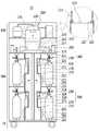
도 1은 본 발명의 일실시 예에 따른 맥주 제조장치를 나타내는 사시도이고, 도 2는 도 1에 따른 맥주 제조장치의 개략적인 수직단면도이고, 도 3은 도 1에 따른 맥주 제조장치의 개략적인 수평단면도이다.FIG. 1 is a perspective view showing a beer manufacturing apparatus according to an embodiment of the present invention, FIG. 2 is a schematic vertical sectional view of a beer manufacturing apparatus according to FIG. 1, and FIG. 3 is a schematic horizontal Sectional view.
도 1 내지 도 3을 참조하면, 본 발명의 일실시 예에 따른 맥주 제조장치(10)는, 냉기를 발생시키는 냉각장치(110)가 구비되는 기계실(100)과, 맥즙이 담긴 케그(KEG)(202)가 장착되는 독립된 공간을 가지는 챔버(210)가 복수개 구비되는 발효실(200)과, 기계실(100)과 발효실(200)을 지지하는 지지부(15)를 포함할 수 있다.1 to 3, a
상기 기계실(100)에는 냉각장치(110)에서 발생하는 냉기를 보관하는 냉기보관부(120)가 구비될 수 있으며, 상기 발효실(200)에는 냉기보관부(120)에 보관된 냉기를 챔버(210) 내부로 공급하는 냉기공급장치(220)가 구비될 수 있다.The
또한, 상기 발효실(200)에는 챔버(210) 내에 장착된 케그(202)에 담긴 맥즙을 발효시키기 위한 발효장치(300)가 구비될 수 있다.The
상기 챔버(210)는 맥즙이 담긴 케그(202)가 장착되는 독립된 공간으로써, 상기 각각의 챔버(210)에는 내부를 밀폐시키는 도어(212)가 구비될 수 있으며, 상기 챔버(210) 내부는 냉기공급장치(220)에 의해 독립적인 온도 조절이 가능하며, 상기 챔버(210) 내부에 장착된 케그(202)에 담긴 맥즙은 발효장치(300)에 의해 독립적인 발효를 통한 맥주 제조가 가능하다.The
일반적으로, 맥주는 맥즙과 효모의 종류에 따라 발효시간, 발효온도 등의 조건을 달리하여 제조하여야 하며, 그에 따라 제조된 맥주의 맛이 달라지게 되는데, 본 발명의 일실시 예에 따른 맥주 제조장치(10)는 독립적인 온도조절과 발효가 가능한 챔버(210)를 복수개 구비하기 때문에, 한 번에 다양한 종류의 맥주를 제조할 수 있다.Generally, the beer must be manufactured under different conditions such as fermentation time, fermentation temperature, etc. depending on the kinds of the wort and yeast, and the taste of the beer thus produced is changed. In the beer manufacturing apparatus according to the embodiment of the present invention, (10) has a plurality of chambers (210) capable of independent temperature control and fermentation, so that various kinds of beer can be produced at one time.
본 발명의 일실시 예에 따른 맥주 제조장치(10)는 효모(yeast)가 살아있는 상태의 맥주를 판매하기 위한 호프집 등과 같은 장소에 설치될 수 있으며, 상기 맥즙이 담긴 케그(202)는 공장으로부터 제조되어 제공될 수 있다.The
예를 들어, 공장에서는 맥즙을 제조하고, 상기 제조된 맥즙을 유통 및 보관을 위한 살균처리를 하고, 상기 살균처리된 맥즙을 케그(202)에 담아 케그캡으로 밀봉하고, 상기 밀봉된 케그를 본 발명에 따른 맥주 제조장치(10)가 설치된 판매장소로 유통시킴으로써, 상기 맥즙이 담긴 케그(202)를 제공할 수 있다.For example, in a factory, a wort is manufactured, a sterilization treatment is performed for distributing and storing the wort, and the sterilized wort is placed in a
그리고 본 발명에 따른 맥주 제조장치(10)가 설치된 판매장소에서는, 상기 맥즙이 담긴 밀봉된 케그(202)를 챔버(210)에 장착시키기만 하면, 발효장치(300)에 의해 밀봉된 상태로 즉, 외부와 접촉되어 오염될 여지 없이 자동으로 발효된 후 숙성되는 과정을 통해 전문지식 없이도 효모가 살아있는 맥주를 쉽게 제조하여 판매할 수 있다.In the sales place where the
본 실시 예에서는 하나의 챔버(210)에 2개의 케그(202)가 장착되도록 구비된 것이 도시되지만, 하나의 챔버(210)에 1개의 케그(202)가 장착되도록 구비될 수도 있으며, 본 발명은 하나의 챔버(210)에 장착되는 케그(202)의 개수에 의해 한정되지 않는다.Although it is shown in the present embodiment that two
다만, 본 실시 예에서와 같이, 하나의 챔버(210)에 2개의 케그(202)가 장착되는 경우에도, 각각의 케그(202)에 담겨진 맥즙을 발효시키기 위한 발효장치(300)는 각각 독립적으로 이루어질 수 있도록 구비될 수 있다.However, as in the present embodiment, even when two
한편, 상기 발효실(200)은 회전 가능하게 구비될 수 있다.Meanwhile, the
예를 들어, 본 실시 예에서와 같이, 지지부(15) 상부에 발효실(200)이 위치하고, 발효실(200) 상부에 기계실(100)이 위치하는 경우에는, 상기 발효실(200)은 지지부(15)와 기계실(100) 사이에서 회전 가능하게 구비될 수 있으며, 이를 위해 발효실(200)과 지지부(15) 사이, 발효실(200)과 기계실(100) 사이에는 상기 발효실(200)의 회전을 위한 로테이팅 베어링, 로터리 댐퍼 등의 구성이 구비될 수 있다.For example, as in the present embodiment, when the
다만, 본 발명은 이에 한정하는 것은 아니며, 지지부(15) 상부에 기계실(100)이 위치하고, 기계실(100) 상부에 발효실(200)이 위치할 수도 있으며, 이 경우 상기 발효실(200)은 기계실(100) 상부에 위치한 상태로 회전 가능하게 구비될 수 있다.However, the present invention is not limited thereto, and the
이와 같이, 상기 발효실(200)이 회전 가능하게 구비되면, 사용자가 발효실(200)을 회전시키면서 복수의 챔버(210) 각각에 케그(202)를 장착시키거나 복수의 챔버(210) 각각에 장착된 케그(202)를 탈착시키기가 편리하다.When the
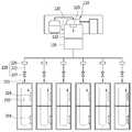
또한, 도 3에서 보이는 바와 같이, 상기 복수의 챔버(210)는 원주방향으로 구획될 수 있다. 그러면, 사용자는 발효실(200)을 회전시키면서 더욱 쉽게 케그(202)를 장착시키고 탈착시킬 수 있다.Further, as shown in FIG. 3, the plurality of
본 발명의 일실시 예에 따른 맥주 제조장치(10)는 상부 대략 기계실(100) 전면에 구비되어 복수의 챔버(210) 각각에 장착된 케그(202)에 담겨진 맥즙의 발효 진행상황, 상기 각각의 챔버(210) 내부 온도 등을 표시하는 디스플레이부(17)를 더 포함할 수 있다.The
상기 냉각장치(110)는 냉매를 이용하여 냉기를 발생시키도록 구성될 수 있는데, 예를 들어 압축기, 응축기, 증발기, 열교환기 등의 구성을 포함하여 이루어질 수 있다.The
상기 냉기보관부(120)는 냉각장치(110)에서 발생하는 냉기를 보관하는 공간(121)을 형성하는 제1 케이스(122)와 제2 케이스(125)를 포함할 수 있다.The
상기 제1 케이스(122)는 냉각장치(110)에서 발생하는 냉기를 공급받을 수 있도록 기계실(100)에 위치하여 고정되며, 상기 제2 케이스(125)는 제1 케이스(122)에 회전 가능하게 구비되어 발효실(200) 회전시 함께 회전할 수 있다.The
또한, 제1 케이스(122)와 제2 케이스(125) 사이에는 제2 케이스(125)가 회전함에 따라 냉기보관부(120)에 보관된 냉기가 누출되는 것을 방지하는 가스켓(127)이 구비될 수 있으며, 제1 케이스(122) 상부에는 냉각장치(110)에서 발생한 냉기를 제2 케이스(125)로 원활하게 공급하는 팬(129)이 구비될 수 있다.A
한편, 상기 제2 케이스(125)에는 냉기공급장치(220)가 연결될 수 있다.Meanwhile, the
도 4는 본 발명의 일실시 예에 따른 냉기공급장치를 설명하기 위한 도면이다.4 is a view for explaining a cold air supply apparatus according to an embodiment of the present invention.
도 4에서 보이는 바와 같이, 본 발명의 일 실시 예에 따른 냉기공급장치(220)는 냉기보관부(120)에 보관된 냉기를 복수의 챔버(210) 각각으로 공급하기 위한 구성으로, 발효실(200)에는 냉기공급장치(220)가 적어도 상기 복수의 챔버(210) 수만큼 구비될 수 있다.4, the cool
상기 냉기공급장치(220)는 제2 케이스(125)에 연결되어 냉기보관부(120)와 챔버(210)를 연결하는 덕트(222)와, 냉기보관부(120)에 보관된 냉기를 덕트(222)를 통해 챔버(210)로 공급하는 냉기공급팬(225)과, 덕트(222)를 개폐하는 덕트개폐부(227)를 포함할 수 있다.The cool
또한, 상기 각각의 챔버(210) 상단에는 덕트(222)에 연결되는 냉기공급구(211)가 형성될 수 있으며, 상기 각각의 챔버(210) 내부에는 히터(219)와 온도센서(미도시)가 구비될 수 있다.A cool
따라서, 상기 각각의 챔버(210) 내부는 온도센서, 냉기공급장치(220) 및 히터(219)에 의해 독립적인 온도 조절이 가능해질 수 있다. 즉, 상기 복수의 챔버(210) 각각에 장착된 케그(202)에 담긴 맥즙의 발효진행 정도에 따라 챔버(210) 내부의 온도를 독립적으로 조절할 수 있다.Therefore, the temperature inside each of the
도 5는 본 발명의 일실시 예에 따른 발효장치를 설명하기 위한 도면이고, 도 6은 본 발명의 일실시 예에 따른 발효장치의 구성도이다.FIG. 5 is a view for explaining a fermentation apparatus according to an embodiment of the present invention, and FIG. 6 is a configuration diagram of a fermentation apparatus according to an embodiment of the present invention.
도 5에서 보이는 바와 같이, 본 발명의 일실시 예에 따른 발효장치(300)는 복수의 챔버(210) 각각에 장착된 케그(202)에 담긴 맥즙을 독립적으로 발효시키기 위한 구성으로, 발효실(200)에는 발효장치(300)가 적어도 상기 복수의 챔버(210) 수만큼 구비될 수 있다.5, the
상기 발효장치(300)는 케그(202)의 케그캡(205)이 결합하는 커플러(230), 커플러(230)에 연결되어 독립된 유로를 형성하는 유로부(304), 유로부(304)에 연결되는 필터부(270), 유로부(304)에 연결되는 펌프(260)를 포함할 수 있다.The
전술한 바와 같이, 본 실시 예에서는 하나의 챔버(210)에 2개의 케그(202)가 장착되는 것이 도시되는데, 이 경우에도 각각의 케그(202)에 담겨진 맥즙을 발효시키기 위한 발효장치(300)는 펌프(260)만을 공유할 뿐 각각 독립적으로 이루어질 수 있다.As described above, in this embodiment, two
즉, 하나의 챔버(210)에 장착된 2개의 케그(202)에 담겨진 맥즙을 각각 독립적으로 발효시키기 위하여, 상기 발효장치(300)는 2개의 케플러(230), 2개의 유로부(304), 2개의 필터부(270)를 포함할 수 있다.That is, in order to independently ferment the wafers contained in the two
물론, 펌프(260)도 2개가 구비될 수 있지만, 본 실시 예에서와 같이 하나의 펌프(260)를 공용으로 사용하면, 상기 발효장치(300)의 구성을 간단히 할 수 있다.Of course, two
상기 커플러(230)에는 가스유로(air line)(232)와 맥즙유로(wort line)(234)가 구비될 수 있다.The
상기 유로부(304)는 커플러(230)의 가스유로(232)와 맥즙유로(234)를 연결하여 독립된 유로를 형성할 수 있다.The
상세히, 상기 유로부(304)는 커플러(230)의 가스유로(232)와 펌프(260)를 연결하는 제1 유로(310)와, 커플러(230)의 맥즙유로(234)와 펌프(260)를 연결하는 제2 유로(320)를 포함할 수 있다.The
또한, 상기 유로부(304)는 제1 유로(310)에 구비되어 케그(202)에 담긴 맥즙 발효시 발생하는 가스를 외부로 배출시키는 가스배출부(312)와, 가스배출부(312)를 개폐시키는 제1 밸브(314)와, 가스배출부(312)와 펌프(260) 사이에 구비되어 제1 유로(310)를 개폐시키는 제2 밸브(315)를 포함할 수 있다.The
또한, 상기 제1 유로(310)에는 케그(202) 내부의 압력을 감지하기 위한 압력센서(317)가 구비될 수 있다. 제1 유로(310)는 커플러(230)의 가스유로(232)를 통해 케그(202)의 내부와 연결되기 때문에, 압력센서(317)가 제1 유로(310)에 위치하더라도 케그(202)의 내부 압력 감지가 가능하다.The
도면에는 도시되지 않지만, 상기 가스배출부(312)에는 외부 공기가 제1 유로(310)로 유입되어 오염되는 것을 방지하는 공기필터가 구비될 수 있으며, 압력센서(317) 및 제1 밸브(314)의 오작동시 압력을 배출할 수 있는 기계식 릴리프밸브가 구비될 수 있다.Although not shown in the drawing, the
상기 필터부(270)는 필터용기(filter bottle)(274)와, 필터용기(274)를 막아 밀폐시키는 필터캡(filter cap)(275)과, 유로부(304)에 연결되되 필터캡(275)이 결합하는 경우에 필터용기(274) 내부와 유로부(304)를 연결하는 필터헤드(filter head)(271)를 포함할 수 있다.The
상기 필터용기(274)는 유로부(304) 살균세척을 위한 살균세척수가 담긴 살균세척용 필터용기일 수 있으며, 또는 맥주에 홉(hop)이나 자연재료 그대로의 맛(flavor)과 향(aroma)을 가미하기 위한 재료가 담긴 스마트 인퓨징(smart infusing)용 필터용기일 수 있으며, 또는 케그(202)에 담긴 맥즙에 공급할 효모(yeast)가 담긴 효모공급용 필터용기일 수 있다.The
상기 필터부(270)는 제2 유로(320)에 구비되어 커플러(230)의 맥즙유로(234)에 연결될 수 있다.The
상기 유로부(304)는 제2 유로(320)에 구비되어 상기 제2 유로(320)를 개폐하는 제3 밸브(325)를 더 포함할 수 있으며, 상기 제3 밸브(325)는 커플러(230)의 맥즙유로(234)와 필터부(270) 사이에 구비될 수 있다.The
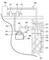
도 7은 도 1에 따른 맥주 제조장치의 챔버 내부를 나타내는 도면이고, 도 8은 도 7의 챔버에 케그가 장착된 상태를 나타내는 도면이고, 도 9는 도 7의 챔버에 케그가 장착되어 형성된 독립된 유로부를 개략적으로 나타내는 도면이다.7 is a view showing the inside of the chamber of the beer manufacturing apparatus shown in Fig. 1, Fig. 8 is a view showing a state in which the cage is mounted in the chamber of Fig. 7, Fig.
먼저, 도 7 및 도 8에서 보이는 바와 같이, 상기 챔버(210)에는 2개의 케그(202)가 장착되도록 지지플레이트(214)가 구비될 수 있으며, 상기 지지플레이트(214)에는 챔버(210) 내로 공급된 냉기가 지지플레이트(214)를 기준으로 아래위로 원활하게 순환될 수 있도록 홀(213)과 틈(216) 등이 형성될 수 있으며, 지지플레이트(214)와 챔버(210)의 하부에는 케그(202)가 안착되는 케그안착부(215)가 구비될 수 있다.7 and 8, the
또한, 챔버(210) 내부에는 커플러(230)가 챔버(210) 상단과 지지플레이트(214) 상단에 고정설치될 수 있는데, 커플러(230)의 가스유로(232)는 제1 유로(310)에 연결되고, 커플러(230)의 맥즙유로(234)는 제2 유로(320)에 연결된 상태로 고정설치될 수 있다.A
도면에는 도시되지 않지만, 커플러(230)는 챔버(210) 상단 또는 지지플레이트(214) 상단에 소정의 높이 조절이 가능한 상태로 고정되도록 코일스프링과 같은 탄성부재에 의해 지지될 수 있다. 그러면, 커플러(230)의 높이를 케그(202)의 크기에 맞게 쉽게 조절 가능하게 됨에 따라, 케그(202)를 케그안착부(215)에 안착시킨 상태에서 케그캡(205)을 커플러(230)에 쉽게 결합시킬 수 있어서 편리하다.Although not shown in the drawings, the
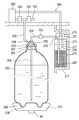
도 9에서 보이는 바와 같이, 케그캡(205)에는 케그(202)에 담긴 맥즙을 케그(202) 외부로 배출시키기 위한 맥즙호스(206)가 케그(202)의 대략 바닥면까지 길게 형성될 수 있으며, 상기 맥즙호스(206)는 케그캡(205)이 커플러(230)에 결합한 경우에 커플러(230)의 맥즙유로(234)에 연결될 수 있다.9, the
또한, 상기 케그캡(205)에는 케그(202) 내부 공간과 연결되어 맥즙 발효시 발생하는 가스를 케그(202) 외부로 배출시키기 위한 가스배출유로(207)가 형성될 수 있으며, 상기 가스배출유로(207)는 케그캡(205)이 커플러(230)에 결합한 경우에 커플러(230)의 가스유로(232)에 연결될 수 있다.A
그러면, 상기 유로부(304)는 케그캡(205)과 커플러(230)가 결합하게 됨에 따라, 제1 유로(310), 제2 유로(320), 커플러(230) 및 케그(202)로 연결되는 폐유로를 형성할 수 있다.As the
따라서, 상기 맥즙이 담긴 케그(202)를 챔버(210) 내에 구비된 케그안착부(215)에 안착시킨 상태에서 케그캡(205)을 커플러(230)에 결합함으로써 상기 맥즙이 담긴 케그(202)를 챔버(210) 내에 장착시킬 수 있으며, 이와 같이 상기 맥즙이 담긴 케그(202)를 챔버(210) 내에 장착시키면, 상기 케그(202)에 담긴 맥즙은 맥즙호스(206)와 맥즙유로(234)를 통해 제2 유로(320)에 연결되고, 상기 맥즙이 담긴 케그(202)의 공간은 가스배출유로(207)와 가스유로(232)를 통해 제1 유로(310)에 연결됨에 따라, 상기 유로부(304)는 폐유로를 형성할 수 있다.Therefore, by coupling the
그러면, 상기 케그(202)에 담긴 맥즙은 펌프(260)에 의해 외부와 접촉되어 오염될 여지 없이 제2 유로(320)로 펌핑될 수 있으며, 상기 케그(202)에 담긴 맥즙 발효시 발생하는 가스는 외부와 접촉되어 오염될 여지 없이 제1 유로(310)와 가스배출부(312)를 통해 외부로 배출될 수 있다.The wastes contained in the
또한, 챔버(210) 내부 일측에는 필터부(270)의 필터용기(274)가 안착되는 필터안착부(217)가 구비될 수 있으며, 상기 필터안착부(217) 상부에는 필터헤드(271)가 유로부(304)에 연결된 상태로 고정설치될 수 있다.A
다만, 본 발명은 이에 한정하는 것은 아니며, 챔버(210) 내부에 별도의 필터안착부(217)가 구비됨이 없이, 필터용기(274)가 챔버(210) 상부에 고정설치된 필터헤드(271)에 결합됨으로써 챔버(210)에 장착될 수도 있다.However, the present invention is not limited to this. The
도 9에서 보이는 바와 같이, 상기 필터헤드(271)에는 커플러(230)의 맥즙유로(234)에 연결되는 제1 필터유로(272)와, 펌프(260)에 연결되는 제2 필터유로(273)가 형성될 수 있으며, 상기 필터헤드(271)는 제1 필터유로(272)가 커플러(230)의 맥즙유로(234)에 연결되고, 제2 필터유로(273)가 펌프(260)에 연결된 상태로 필터안착부(217) 상부에 고정설치될 수 있다.9, the
또한, 상기 필터캡(275)에는 대략 필터용기(274) 바닥면까지 길게 형성된 제1 필터호스(276)와, 제1 필터호스(276)보다 짧게 형성된 제2 필터호스(277) 형성될 수 있으며, 제1 필터호스(276)와 제2 필터호스(277) 각각은 상기 필터캡(275)이 필터헤드(271)에 결합한 경우에 제1 필터유로(272)와 제2 필터유로(273)에 연결될 수 있다.The
따라서, 상기 필터용기(274)의 필터캡(275)을 필터헤드(271)에 결합함으로써 상기 필터용기(274)를 챔버(210) 내에 장착시킬 수 있으며, 이와 같이 상기 필터용기(274)를 챔버(210) 내에 장착시키면, 상기 필터용기(274) 내부는 제1 필터호스(276)와 제1 필터유로(272)를 통해 커플러(230)의 맥즙유로(234)에 연결될 수 있으며, 제2 필터호스(277)와 제2 필터유로(273)를 통해 펌프(260)에 연결될 수 있다.The
그러면, 상기 필터부(270)의 용도에 따라 적절한 필터용기(274)를 챔버(210) 내에 장착시킴으로써, 외부와 접촉되어 오염될 여지없이 자동으로 쉽게 케그(202)에 담긴 맥즙으로부터 효모가 살아있는 맥주를 제조할 수 있다.By mounting the
예를 들어, 상기 필터용기(274)로서 내부에 살균세척수가 담긴 살균세척용 필터용기를 사용하면, 펌프(260)에 의해 상기 필터용기(274)에 담긴 살균세척수를 유로부(304)로 순환시킴으로써, 외부와 접촉되어 오염될 여지없이 자동으로 유로부(304)를 살균세척할 수 있다.For example, when the
또한, 상기 필터용기(274)로서 내부에 홉이나 자연재료 그대로의 맛과 향을 우려내기 위한 재료가 담긴 스마트 인퓨징용 필터용기를 사용하면, 펌프(260)에 의해 케그(202)에 담긴 맥즙을 상기 필터용기(274) 내부로 순환시킴으로써, 외부와 접촉되어 오염될 여지없이 자동으로 맥주에 맛과 향을 우려낼 수 있다.When the
또한, 상기 필터용기(274)로서 내부에 맥즙을 발효시키기 위한 효모가 담긴 효모공급용 필터용기를 사용하면, 펌프(260)에 의해 케그(202)에 담긴 맥즙을 상기 필터용기(274) 내부로 순환시킴으로써, 외부와 접촉되어 오염될 여지없이 자동으로 맥즙에 효모를 공급할 수 있다.When the
한편, 도 9에서 보이는 바와 같이, 상기 케그(202)가 안착되는 케그안착부(215)에는 무게센서(40)가 구비될 수 있다.Meanwhile, as shown in FIG. 9, the
상기 무게센서(40)는 케그(202)에 담긴 맥즙의 발효진행 정도에 따른 상기 케그(202)의 무게 변화를 측정하기 위한 것으로서, 케그안착부(215) 하단에 부착 가능한 로드셀(load cell)이 사용될 수 있다.The
또한, 케그안착부(215) 상부와 케그(202)의 하부에는 케그(202)가 케그안착부(215)의 정확한 위치에 안착되도록 가이드하는 가이드부(208,218)가 형성될 수 있다. 예를 들어, 상기 케그(202)의 하부에는 소정형상의 돌기(208)가 형성되고, 상기 케그안착부(215)의 상부에는 상기 돌기(208)가 끼움되도록 상기 돌기(208) 형상에 상응하는 형상을 갖는 돌기홈(218)이 형성될 수 있다.
그러면, 상기 케그(202)는 케그안착부(215)의 정확한 위치에 안착될 수 있게 됨에 따라 케그안착부(215)에 구비된 무게센서(40)의 센터에 해당하는 정확한 위치에 상기 케그(202)를 안착시킬 수 있으며, 그에 따라 케그(202)가 무게센서(40)와 틀어져 안착되는 경우에 발생하는 무게 변화의 측정오차를 최소화시킬 수 있어서 상기 케그(202) 내에 담긴 맥즙의 발효진행에 따른 무게변화를 보다 정확하게 측정할 수 있다.As the
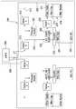
도 10은 본 발명의 일실시 예에 따른 맥주 제조장치의 구성도이다.10 is a configuration diagram of a beer manufacturing apparatus according to an embodiment of the present invention.
도 10을 참조하면, 본 발명의 일실시 예에 따른 맥주 제조장치(10)는 냉기공급장치(220)를 제어하여 복수의 챔버(210) 각각의 내부 온도를 조절하며, 발효장치(300)를 제어하여 복수의 챔버(210) 각각에 장착된 케그(202)에 담겨진 맥즙을 독립적으로 발효시키는 제어부(20)를 포함할 수 있다.10, a
또한, 본 발명의 일실시 예에 따른 맥주 제조장치(10)는 케그(202)에 담긴 맥즙의 발효시간, 발효온도 등의 구체적인 발효조건 등이 입력되는 입력부(60)를 포함할 수 있다.The
상기 입력부(60)는 사용자가 직접 입력 가능하도록 구비될 수도 있으나, 바코드나 QR(Quick Response)코드 형태로 저장된 정보를 읽을 수 있는 스캐너 등으로 구비됨이 바람직하다.The
예를 들어, 케그캡(205) 상단에는 케그(202)에 담긴 맥즙의 종류, 사용할 효모의 종류, 발효조건, 홉(hop)이나 자연재료 그대로의 맛(flavor)과 향(aroma)을 가미할 것인지 가미한다면 어떠한 재료를 쓸 것인지 등에 대한 정보가 저장된 바코드 또는 QR코드가 형성될 수 있으며, 상기 입력부(60)는 케그캡(205) 상단에 형성된 바코드 또는 QR코드를 인식할 수 있는 스캐너 형태로 구비될 수 있다.For example, at the top of the
따라서, 상기 제어부(20)는 입력부(60)를 통해 입력된 정보, 챔버(210) 내에 구비된 온도센서(30)에서 감지된 온도 및 무게센서(40)에서 감지된 케그(202)의 무게변화 측정값 등을 기초로 냉기공급장치(200)의 냉기공급팬(225), 덕트개폐부(227) 및 챔버(210) 내에 구비된 히터(219)를 제어함으로써, 상기 복수의 챔버(210) 각각의 내부 온도를 상기 케그(202) 내에 담긴 맥즙의 발효진행 정도에 따라 독립적으로 조절할 수 있다.The
또한, 상기 제어부(20)는 입력부(60)를 통해 입력된 정보, 압력센서(317)에서 감지된 압력 및 무게센서(40)에서 감지된 케그(202)의 무게변화 측정값 등을 기초로 발효장치(300)의 펌프(260), 제1 밸브(314), 제2 밸브(315) 및 제3 밸브(325)를 제어함으로써, 상기 복수의 챔버(210) 각각에 장착된 케그(202)에 담겨진 맥즙을 독립적으로 발효시킬 수 있다.The
상술한 바와 같은 구성을 가지는 본 발명의 일실시 예에 따른 맥주 제조장치에 의하면, 공장에서 제조되어 제공된 맥즙이 담겨 밀봉된 케그(202)를 챔버(210)에 장착하기만 하면 전문지식 없이도 외부와 접촉되어 오염될 여지 없이 자동으로 쉽게 효모가 살아있는 상태의 맥주를 제조할 수 있으며, 독립적으로 온도조절이 가능하고 독립적인 발효가 가능한 챔버를 복수개 구비하기 때문에 한 번에 다양한 종류의 맥주를 제조할 수 있다.According to the beer manufacturing apparatus of the present invention having the above-described structure, when the
이하, 본 발명에 따른 맥주 제조장치를 이용한 맥주 제조방법에 대하여 상세히 설명한다.Hereinafter, a method for manufacturing beer using the beer manufacturing apparatus according to the present invention will be described in detail.
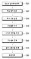
도 11은 본 발명의 일실시 예에 따른 맥주 제조장치를 이용한 맥주 제조방법을 나타내는 흐름도이다.11 is a flowchart illustrating a method of manufacturing beer using a beer manufacturing apparatus according to an embodiment of the present invention.
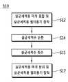
도 11을 참조하면, 본 발명의 일실시 예에 따른 맥주 제조장치(10)를 이용한 맥주 제조방법은, 유로부(304) 살균세척 단계(S10), 케그(202) 장착 단계(S20), 효모 공급 단계(S30), 1차 발효 단계(S40), 스마트 인퓨징(smart infusing) 단계(S50), 2차 발효 단계(S60), 콜드 브레이킹(cold breaking) 단계(S70) 및 숙성 단계(S80)를 포함할 수 있다.11, a beer manufacturing method using a
상기 유로부(304) 살균세척 단계(S10)는 맥즙이 담긴 케그(202)를 챔버(210) 내에 장착시키기 전에 챔버(210) 내에 고정설치된 커플러(230)의 맥즙유로(234)와 가스유로(232)를 연결하는 유로부(304)를 살균세척하기 위한 단계로서, 필터부(270)의 필터용기(274)를 내부에 살균세척수가 담겨진 살균세척용 필터용기로 사용함으로써 수행될 수 있다.The sterilizing cleaning step S10 of the
상기 케그(202) 장착 단계(S20)는, 맥즙이 담긴 케그(202)의 케그캡(205)을 커플러(230)에 결합하여 상기 맥즙이 담긴 케그(202)의 내부를 상기 살균세척된 유로부(304)에 연결하는 단계로서, 상기 맥즙이 담긴 케그(202)를 챔버(210) 내에 구비된 케그안착부(215)에 안착시킨 상태에서 케그캡(205)을 커플러(230)에 결합시킴으로써, 케그(202) 내부 공간을 가스배출유로(207)와 가스유로(232)를 통해 제1 유로(310)에 연결하고, 케그(202)에 담겨진 맥즙을 맥즙호스(206)와 맥즙유로(234)를 통해 제2 유로(320)에 연결할 수 있다.The mounting step S20 of the
상기 효모 공급 단계(S30)는, 상기 챔버(210) 내에 장착된 케그(202)에 담긴 맥즙을 발효시키기 위한 효모를 공급하는 단계로서, 필터부(270)의 필터용기(274)를 내부에 맥즙을 발효시키기 위한 효모가 담긴 효모공급용 필터용기를 사용함으로써 수행될 수 있다.The yeast supplying step S30 is a step of supplying yeast for fermenting the wort contained in the
상기 1차 발효 단계(S40)는, 유로부(304)에 구비된 가스배출부(312)를 열어 상기 케그(202)에 담긴 맥즙 발효시 발생하는 가스를 외부로 배출시키는 단계이다.The primary fermentation step S40 is a step of opening the
상기 케그(202)에 담긴 맥즙에 효모가 공급되면 바로 발효가 시작되고, 발효가 시작되면 케그(202) 내부로 공급된 효모가 활성화되고 알코올 생성이 활발히 이루어지게 되면서 가스가 발생하게 되는데, 상기 1차 발효 단계(S40)는 발효 시작 후 소정시간 동안 발생하는 가스를 외부로 배출시키기 위한 단계로서, 이때 제어부(20)는 제2 밸브(315)와 제3 밸브(325)를 닫고, 제1 밸브(314)를 오픈함으로써, 발효시작 후 소정시간 동안 케그(202) 내부에서 발생하는 가스를 가스배출부(312)를 통해 외부로 배출시킬 수 있다.When yeast is supplied to the bees contained in the
상기 스마트 인퓨징 단계(S50)는, 맥주에 홉이나 자연재료 그대로의 맛과 향을 우려내기 위한 단계로서, 필터부(270)의 필터용기(274)를 내부에 맛과 향을 우려내기 위한 재료가 담긴 스마트 인퓨징용 필터용기를 사용함으로써 수행될 수 있다.The smart infusing step S50 is a step for raising the taste and flavor of the beer as it is as a hop or a natural material. The smart infusing step S50 includes a step of forming a
상기 2차 발효 단계(S60)는, 상기 가스배출부(312)를 닫아 상기 케그(202)에 담긴 맥즙 발효시 발생하는 가스를 이용하여 상기 1차 발효된 맥즙을 자연 탄산화시키는 단계로서, 이때 제어부(20)는 제1 밸브(325)를 닫아 케그(202) 내부에 발생된 가스가 가스배출부(312)를 통해 외부로 배출되지 못하도록 할 수 있다.The secondary fermentation step (S60) is a step of carbonating the primary fermented wort using the gas generated when the wort fermented in the keg (202) is closed by closing the gas discharging part (312) The
상기 콜드 브레이킹 단계(S70)는, 챔버(210) 내부 온도를 대략 2℃ 이하로 낮춤으로써, 2차 발효된 맥주에 섞여져 있는 단미, 단백질, 효모 등의 침전물을 케그(202) 바닥으로 가라앉게 하는 단계이다.The cold breaking step S70 may be performed by lowering the internal temperature of the
상기 숙성 단계(S80)는, 상기 콜드 브레이킹 단계(S70)까지 완료된 맥주를 숙성시키는 단계로서, 챔버(210) 내부 온도를 기 설정된 소정온도로 유지한 상태로 기 설정된 소정시간 동안 유지시키는 단계이다.The aging step S80 is a step of aging the beer completed until the cold breaking step S70 and maintaining the internal temperature of the
이하, 본 발명의 일실시 예에 따른 맥주 제조장치를 이용한 유로부 살균세척 방법에 대하여 도면을 참조하여 상세히 설명한다.Hereinafter, a method of cleaning a path portion disinfection using a beer manufacturing apparatus according to an embodiment of the present invention will be described in detail with reference to the drawings.
상기 유로부 살균세척 단계(S10)는 챔버(210)에 맥즙이 담긴 케그(202)를 장착하여 발효시키기 전에 미리 유로부(304)를 살균세척하기 위한 것이다.The sterilizing and
도 12 내지 도 14는 본 발명의 일실시 예에 따른 맥주 제조장치를 이용한 유로부 살균세척 단계를 설명하기 위한 도면으로서, 도 12는 커플러에 살균세척용 마개를 결합한 상태를 개략적으로 나타내는 도면이고, 도 13은 살균세척수가 유로부를 순환하는 상태를 개략적으로 나타내는 도면이고, 도 14는 본 발명의 일실시 예에 따른 유로부의 살균세척 단계를 나타내는 흐름도이다.FIGS. 12 to 14 are views for explaining steps of cleaning a path portion sterilizing using a beer manufacturing apparatus according to an embodiment of the present invention, FIG. 12 is a view schematically showing a state where a sterilizing cleaning stopper is coupled to a coupler, FIG. 13 is a view schematically showing a state in which sterilizing washing water circulates through the flow path portion, and FIG. 14 is a flowchart showing a sterilizing washing step of the flow path portion according to an embodiment of the present invention.
도 12 및 도 13을 참조하면, 챔버(210) 내에 케그(202)를 장착하기 전에 자동으로 유로부(304)를 살균세척하기 위한, 본 발명의 일실시 예에 따른 맥주 제조장치(10)는, 커플러(230)에 결합하여 유로부(304)를 폐유로가 되도록 하는 살균세척용 마개(280)를 더 포함할 수 있다.12 and 13, a
즉, 자동으로 유로부(304) 살균세척을 위한 본 발명의 일실시 예에 따른 맥주 제조장치(10)는, 챔버(210), 챔버(210) 내에 고정설치되며 맥즙유로(234)와 가스유로(232)가 구비되는 커플러(230), 커플러(230)의 맥즙유로(234)와 가스유로(232)를 연결하는 유로부(304), 커플러(230)에 결합하여 유로부(304)가 폐유로가 되도록 하는 살균세척용 마개(280), 유로부(304)에 연결되며 내부에 살균세척수가 담긴 살균세척용 필터용기(285), 유로부(304)에 연결되는 펌프(260), 살균세척용 필터용기(285)에 담긴 살균세척수가 상기 폐유로가 된 유로부(304)를 순환하도록 펌프(260)의 작동을 제어하는 제어부(20)를 포함할 수 있다.That is, the
상기 살균세척용 마개(280)에는 커플러(230)에 결합한 경우에 맥즙유로(234)와 가스유로(232)를 연결하는 공간(283)이 구비될 수 있다.The sterilizing
그러면, 맥즙유로(234)와 가스유로(232)가 관통 형성된 커플러(230)의 어느 한 일측의 맥즙유로(234)와 가스유로(232)는 유로부(304)에 의해 연결되고, 다른 일측의 맥즙유로(234)와 가스유로(232)는 상기 살균세척용 마개(280)에 의해 연결됨에 따라, 상기 유로부(304)는 폐유로를 형성할 수 있게 된다.The
상기 유로부(304)는 커플러(230)의 가스유로(232)와 펌프(260)를 연결하는 제1 유로(310), 커플러(230)의 맥즙유로(234)와 펌프(260)를 연결하는 제2 유로(320), 제1 유로(310)에 구비되는 가스배출부(312), 가스배출부(312)를 개폐시키는 제1 밸브(314), 가스배출부(312)와 펌프(260) 사이에 구비되어 제1 유로(310)를 개폐시키는 제2 밸브(315)를 포함할 수 있다.The
상기 살균세척용 필터용기(285)는 제2 유로(320)에 연결될 수 있다.The sterilizing cleaning
상기 유로부(304)는 커플러(230)의 맥즙유로(234)와 살균세척용 필터용기(285) 사이에 구비되어 제2 유로(320)를 개폐시키는 제3 밸브(325)를 더 포함할 수 있다.The
상기 챔버(210)에는 제2 유로(320)에 연결된 상태로 고정설치되되 살균세척용 필터용기(285)의 필터캡(275)이 결합하는 경우에 살균세척용 필터용기(285) 내부와 제2 유로(320)를 연결하는 필터헤드(271)가 구비될 수 있다.The
상기 필터헤드(271)에는 커플러(230)의 맥즙유로(234)에 연결되는 제1 필터유로(272)와, 펌프(260)에 연결되는 제2 필터유로(273)가 형성될 수 있다.The
상기 필터캡(275)에는 살균세척용 필터용기(285)에 담긴 거의 모든 살균세척수가 외부로 배출될 수 있도록 상기 살균세척용 필터용기(285) 내부 바닥면까지 길게 형성되는 제1 필터호스(276)와, 상기 살균세척용 필터용기(285)에 담겨진 살균세척수의 수면에 닿지 않도록 상기 살균세척용 필터용기(285) 내부 공간에 연결되는 제2 필터호스(277)가 구비될 수 있다.The
또한, 필터캡(275)이 필터헤드(271)에 결합한 경우에, 상기 필터캡(275)의 제1 필터호스(276)는 상기 필터헤드(271)의 제1 필터유로(272)에 연결되고, 상기 필터캡(275)의 제2 필터호스(277)는 상기 필터헤드(271)의 제2 필터유로(273)에 연결될 수 있다.The
상기 펌프(260)는 양방향 구동 예를 들어, 시계방향 구동과 반시계방향 구동이 가능한 펌프가 사용될 수 있다.The
그러면, 제어부(20)는 펌프(260)의 작동 방향을 제어함으로써 살균세척용 필터용기(285)에 담긴 살균세척수를 상기 폐유로가 된 유로부(304)로 순환시킨 후 다시 살균세척용 필터용기(285)로 회수할 수 있다.The
도 14를 참조하면, 본 발명의 일실시 예에 따른 유로부 살균세척 방법(S10)은, 유로부(304)가 폐유로가 되도록 커플러(230)에 살균세척용 마개(280)를 결합하고 상기 유로부(304)에 살균세척용 필터용기(285)를 연결하는 살균세척용 마개 결합 및 살균세척용 필터용기 장착 단계(S12), 상기 유로부(304)에 연결된 펌프(260)를 작동시켜 상기 살균세척용 필터용기(285)에 담긴 살균세척수를 소정시간 동안 상기 폐유로가 된 유로부(304)로 순환시키는 살균세척수 순환 단계(S14), 상기 펌프(260)를 반대방향으로 작동시켜 상기 순환하는 살균세척수를 상기 살균세척용 필터용기(285)로 회수하는 살균세척수 회수 단계(S15), 상기 커플러(230)에 결합된 살균세척용 마개(280)를 분리하고 상기 유로부(304)에 연결된 살균세척용 필터용기(285)를 분리하는 살균세척용 마개 분리 및 살균세척용 필터용기 탈착 단계(S17)를 포함할 수 있다.14, the method (S10) for sterilizing a passage portion according to an embodiment of the present invention includes coupling the
예를 들어, 상기 살균세척수 순환 단계(S14)는 제어부(20)에 의한 펌프(260) 작동이 반시계방향으로 이루어지도록 함으로써 수행될 수 있다.For example, the sterilizing wash water circulation step (S14) may be performed by causing the controller (20) to operate the pump (260) counterclockwise.
도 13에서 보이는 바와 같이, 펌프(260)가 반시계방향으로 작동하면, 살균세척용 필터용기(285) 내부 바닥면까지 길게 형성된 제1 필터호스(276)에 의해 상기 살균세척용 필터용기(285)에 담긴 살균세척수는 유로부(304)로 펌핑되어 시계방향으로 순환한 후 다시 제2 필터호스(277)를 통해 상기 살균세척용 필터용기(285)로 회수됨에 따라, 상기 살균세척용 필터용기(285)에 담긴 살균세척수는 펌프(260)의 반시계방향 작동에 의해 계속해서 유로부(304)를 시계방향으로 순환할 수 있다.13, when the
이때, 상기 살균세척수 회수 단계(S15)는 제어부(20)에 의한 펌프(260) 작동이 상기 살균세척수 순환 단계(S14)에서의 작동방향과 반대 방향 즉, 시계방향으로 이루어지도록 함으로써 수행될 수 있다.At this time, the sterilizing wash water recovery step S15 may be performed by causing the
이와 같이, 펌프(260)가 시계방향으로 작동하면, 살균세척수는 유로부(304)를 반시계방향으로 순환하게 되는데, 이때 제2 필터호스(277)는 살균세척수의 표면에 닿지 않는 상태이기 때문에, 살균세척용 필터용기(285) 내의 살균세척수는 더이상 유로부(304)로 펌핑되지 않는 상태에서, 유로부(304)에 잔존하는 살균세척수만 살균세척용 필터용기(285)로 회수될 수 있게 된다.When the
상술한 바와 같이, 자동으로 유로부(304) 살균세척을 위한 본 발명의 일실시 예에 따른 맥주 제조장치(10) 및 이를 이용한 유로부(304) 살균세척 방법(S10)은, 커플러(230)에 맥즙이 담긴 케그(202)를 결합하기 전에 살균세척용 마개(280)를 먼저 결합시켜 상기 유로부(304)를 폐유로로 만들고, 살균세척수가 담긴 살균세척용 필터용기(285)를 상기 유로부(304)에 연결한 후, 펌프(260) 작동에 의해 살균세척수가 상기 폐유로가 된 유로부(304)를 순환하도록 함으로써, 케그(202) 장착 전에 유로부(304)를 외부와 접촉되어 오염될 여지없이 자동으로 유로부(304) 살균세척이 이루어질 수 있도록 한 것이다.As described above, the
이하에서는 본 발명의 일실시 예에 따른 맥주 제조장치를 이용한 스마트 인퓨징 방법에 대하여 도면을 참조하여 상세히 설명한다.Hereinafter, a smart infusion method using a beer manufacturing apparatus according to an embodiment of the present invention will be described in detail with reference to the drawings.
상기 스마트 인퓨징 단계(S50)는 맥즙에 홉이나 자연재료 그대로의 맛과 향을 우려내기 위한 것으로서, 본 발명에 따른 맥주 제조장치(10)를 이용한 맥주 제조시, 제조하고자 하는 맥주의 레시피에 따라 선택적으로 진행될 수 있다.The smart infusing step (S50) is for raising the taste and aroma of the bean jam as it is as a hop or natural material. In the beer manufacturing process using the
여기서, 스마트 인퓨징(smart infusing)은 자동으로 맥즙에 홉이나 자연재료 그대로의 맛과 향을 우려내는 것을 의미하는 것으로서, 맥주의 풍미를 더욱 풍성하게 더해주기 위해 홉을 추가하는 드라이 호핑(dry hopping)을 포함한다.Here, smart infusing automatically refers to the taste and aroma of hops and natural ingredients in the juice, and it is a method of adding dry hopping to add more flavor of beer ).
도 15 내지 도 18은 본 발명의 일실시 예에 따른 맥주 제조장치를 이용한 스마트 인퓨징 방법을 설명하기 위한 도면으로서, 도 15는 커플러에 맥즙이 담긴 케그를 결합한 상태를 개략적으로 나타내는 도면이고, 도 16은 케그에 담긴 맥즙이 유로부를 순환하는 상태를 개략적으로 나타내는 도면이고, 도 17은 본 발명의 일실시 예에 따른 스마트 인퓨징 방법을 나타내는 흐름도이고, 도 18은 본 발명의 다른 실시 예에 따른 스마트 인퓨징 방법을 나타내는 흐름도이다.15 to 18 are diagrams for explaining a smart infusing method using a beer making apparatus according to an embodiment of the present invention, wherein FIG. 15 is a view schematically showing a state in which a coupler is coupled with a cake containing wort, FIG. 17 is a flowchart showing a smart infusing method according to an embodiment of the present invention, and FIG. 18 is a flowchart illustrating a smart infusing method according to another embodiment of the present invention Figure 6 is a flow chart illustrating a smart in fusing method.
도 15 및 도 16을 참조하면, 스마트 인퓨징(smart infusing)을 위한 본 발명의 일실시 예에 따른 맥주 제조장치(10)는, 챔버(210), 챔버(210) 내에 고정설치되며 맥즙유로(234)와 가스유로(232)가 구비되는 커플러(230), 커플러(230)의 맥즙유로(234)와 가스유로(232)를 연결하는 유로부(304), 커플러(230)에 결합하여 유로부(304)에 연결된 상태로 챔버(210) 내에 장착된 맥즙이 담긴 케그(202), 유로부(304)에 연결되며 내부에 상기 케그(202)에 담긴 맥즙에 맛과 향을 우려내기 위한 재료가 담긴 스마트 인퓨징용 필터용기(287), 유로부(304)에 연결되는 펌프(260), 상기 스마트 인퓨징용 필터용기(287)에 담긴 재료가 상기 케그(202)에 담긴 맥즙에 우려지도록 펌프(260)의 작동을 제어하는 제어부(20)를 포함할 수 있다.15 and 16, a
여기서, 상기 스마트 인퓨징용 필터용기(287) 내부에 담긴 재료는, 상기 케그(202)에 담긴 맥즙에 맛과 향을 우려내기 위한 재료 예를 들어, 홉이나 오렌지 peel, Oak 나무 조각, 바닐라 등의 자연재료일 수 있다.The material contained in the smart
또한, 상기 맥즙이 담긴 케그(202)가 커플러(230)에 결합하여 유로부(304)에 연결되면, 맥즙유로(234)와 가스유로(232)가 관통 형성된 커플러(230)의 어느 한 일측의 맥즙유로(234)와 가스유로(232)는 유로부(304)에 의해 연결되고, 다른 일측의 맥즙유로(234)와 가스유로(232)는 상기 맥즙이 담긴 케그(202)에 의해 연결됨에 따라, 상기 유로부(304)는 폐유로를 형성할 수 있다.When the purged
상기 유로부(304)는 커플러(230)의 가스유로(232)와 펌프(260)를 연결하는 제1 유로(310), 커플러(230)의 맥즙유로(234)와 펌프(260)를 연결하는 제2 유로(320), 제1 유로(310)에 구비되는 가스배출부(312), 가스배출부(312)를 개폐시키는 제1 밸브(314), 가스배출부(312)와 펌프(260) 사이에 구비되어 제1 유로(310)를 개폐시키는 제2 밸브(315)를 포함할 수 있다.The
상기 스마트 인퓨징용 필터용기(287)는 제2 유로(320)에 연결될 수 있다.The smart
상기 유로부(304)는 커플러(230)의 맥즙유로(234)와 스마트 인퓨징용 필터용기(287) 사이에 구비되어 제2 유로(320)를 개폐시키는 제3 밸브(325)를 더 포함할 수 있다.The
상기 케그(202)에는 내부를 밀폐시키며, 커플러(230)에 결합하여 상기 케그(202) 내부를 유로부(304)에 연결시키는 케그캡(205)이 구비될 수 있다.The
상기 케그캡(205)에는 케그(202)에 담긴 거의 모든 맥즙을 외부로 배출시킬 수 있도록 상기 케그(202) 내부 바닥면까지 길게 형성되는 맥즙호스(206)와, 상기 케그(202)에 담긴 맥즙 발효시 발생하는 가스가 외부로 배출될 수 있도록 상기 케그(202) 내부 공간과 연결되는 가스배출유로(207)가 구비될 수 있다.The
또한, 케그캡(205)이 커플러(230)에 결합한 경우에, 상기 케그캡(205)의 맥즙호스(206)는 상기 커플러(230)의 맥즙유로(234)에 연결되고, 상기 케그캡(205)의 가스배출유로(207)는 상기 커플러(230)의 가스유로(232)에 연결될 수 있다.When the
상기 챔버(210)에는 제2 유로(320)에 연결된 상태로 고정설치되되 스마트 인퓨징용 필터용기(287)의 필터캡(275)이 결합하는 경우에 스마트 인퓨징용 필터용기(287) 내부와 제2 유로(320)를 연결하는 필터헤드(271)가 구비될 수 있다.In the case where the
상기 필터헤드(271)에는 커플러(230)의 맥즙유로(234)에 연결되는 제1 필터유로(272)와, 펌프(260)에 연결되는 제2 필터유로(273)가 형성될 수 있다.The
상기 필터캡(275)에는 상기 스마트 인퓨징용 필터용기(287)로 유입된 거의 모든 맥즙을 다시 케그(202)로 회수할 수 있도록 상기 스마트 인퓨징용 필터용기(287) 내부 바닥면까지 길게 형성되는 제1 필터호스(276)와, 상기 스마트 인퓨징용 필터용기(287)로 유입된 맥즙이 상기 스마트 인퓨징용 필터용기(287)에 담겨진 재료를 채울 수 있도록 상기 스마트 인퓨징용 필터용기(287) 내부 공간에 연결되는 제2 필터호스(277)가 구비될 수 있다.The
또한, 필터캡(275)이 필터헤드(271)에 결합한 경우에, 상기 필터캡(275)의 제1 필터호스(276)는 상기 필터헤드(271)의 제1 필터유로(272)에 연결되고, 상기 필터캡(275)의 제2 필터호스(277)는 상기 필터헤드(271)의 제2 필터유로(273)에 연결될 수 있다.The
상기 펌프(260)는 양방향 구동 예를 들어, 시계방향 구동과 반시계방향 구동이 가능한 펌프가 사용될 수 있다.The
그러면, 제어부(20)는 펌프(260)의 작동 방향을 제어함으로써 상기 케그(202)에 담긴 맥즙을 스마트 인퓨징용 필터용기(287)로 유입시킨 후 다시 케그(202)로 회수할 수 있다.Then, the
상기 제어부(20)는 상기 케그(202)에 담긴 맥즙이 상기 스마트 인퓨징용 필터용기(287) 내부로 유입되도록 상기 펌프(20)의 작동을 제어함으로써, 상기 스마트 인퓨징용 필터용기(287)에 담긴 재료의 맛과 향을 상기 케그(202)에 담긴 맥즙에 우려낼 수 있다.The
예를 들어, 상기 제어부(20)는 상기 케그(202)에 담긴 맥즙이 유로부(304)를 순환하도록 펌프(260)의 작동을 제어할 수도 있으며, 상기 케그(202)에 담긴 맥즙이 상기 스마트 인퓨징용 필터용기(287) 내부에 소정시간 동안 침지되었다가 다시 상기 케그(202)로 회수되는 과정이 반복적으로 일어나도록 펌프(260)의 작동을 제어할 수도 있다.For example, the
또한, 스마트 인퓨징용 필터용기(287)와 펌프(260) 사이에는 수위센서(level sensor)(327)가 구비될 수 있다.A
그러면, 상기 제어부(20)가 수위센서(327)가 맥즙을 감지한 경우에 펌프(260)의 작동을 정지하면, 상기 스마트 인퓨징용 필터용기(287) 내부로 유입된 맥즙은 상기 스마트 인퓨징용 필터용기(287)에 담겨진 재료에 침지된 상태를 유지할 수 있으며, 그에 따라 상기 스마트 인퓨징용 필터용기(287)에 담긴 재료가 상기 스마트 인퓨징용 필터용기(287)로 유입된 맥즙에 우려질 수 있게 된다.If the
도 17을 참조하면, 본 발명의 일실시 예에 따른 스마트 인퓨징 방법(S50)은, 상기 유로부(304)에 스마트 인퓨징용 필터용기(287)를 연결하는 스마트 인퓨징용 필터용기 장착 단계(S51)와, 상기 유로부(304)에 연결된 펌프(260)를 작동시켜 상기 케그(202)에 담긴 맥즙에 상기 스마트 인퓨징용 필터용기(287)에 담긴 재료를 우려내는 인퓨징(infusing) 단계(S52)를 포함할 수 있다.17, a smart infusing method S50 according to an embodiment of the present invention includes a smart infusion filter container mounting step S51 for connecting a smart
여기서, 상기 필터용기 장착 단계(S51)는 상기 유로부 살균세척 단계(S10) 이후 또는 상기 효모 공급 단계(S30) 이후에 이루어질 수 있다.Here, the filter container mounting step (S51) may be performed after the sterilizing cleaning step (S10) or after the yeast supplying step (S30).
예를 들어, 상기 효모 공급 단계(S30)가 필터부(270)의 필터용기(274)를 효모 공급용 필터용기를 사용하여 이루어지는 경우에는, 상기 필터용기 장착 단계(S51)는 상기 효모 공급 단계(S30) 이후 즉, 상기 효모 공급용 필터용기가 탈착된 이후에 이루어질 수 있다.For example, when the yeast supply step S30 is performed using the
또는, 상기 효모 공급 단계(S30)가 필터부(270)의 필터용기(274)를 효모 공급용 필터용기를 사용하여 이루어지는 경우가 아닌 경우에는, 상기 필터용기 장착 단계(S51)는 상기 유로부 살균세척 단계(S10) 이후 즉, 살균세척용 필터용기(285)가 탈착된 이후에 이루어질 수 있다.Alternatively, if the yeast supply step S30 is not the case where the
상기 인퓨징 단계(S52)는 펌프(260)를 작동시켜 소정시간 동안 케그(202)에 담긴 맥즙을 유로부(304)로 순환시키는 맥즙 순환 단계(S53)와, 상기 펌프(260)를 반대방향으로 작동시켜 상기 순환하는 맥즙을 상기 케그(202) 내부로 회수하는 맥즙 회수 단계(S54)를 포함할 수 있다.The infusing step S52 includes a wax circulation step S53 for circulating the wort contained in the
예를 들어, 상기 맥즙 순환 단계(S53)는 제어부(20)에 의한 펌프(260) 작동이 시계방향으로 이루어지도록 함으로써 수행될 수 있다.For example, the wort circulation step S53 may be performed by causing the
도 16에서 보이는 바와 같이, 펌프(260)가 시계방향으로 작동하면, 케그(202) 내부 바닥면까지 길게 형성된 맥즙호스(206)에 의해 상기 케그(202)에 담긴 맥즙은 유로부(304)로 펌핑되어 반시계방향으로 순환한 후 다시 가스배출유로(207)를 통해 케그(202)로 회수됨에 따라, 상기 케그(202)에 담긴 맥즙은 펌프(260)의 시계방향 작동에 의해 계속해서 유로부(304)를 반시계방향으로 순환할 수 있다.16, when the
그러면, 유로부(304)를 순환하는 맥즙 중 일정량은 항상 스마트 인퓨징용 필터용기(287)에 침지된 상태를 유지할 수 있기 때문에, 상기 유로부(304)를 순환하는 맥즙에는 상기 스마트 인퓨징용 필터용기(287)에 담긴 재료의 맛과 향이 우려내 질 수 있다.Since a certain amount of the wort circulating through the
이때, 상기 맥즙 회수 단계(S54)는 제어부(20)에 의한 펌프(260) 작동이 상기 맥즙 순환 단계(S53)에서의 작동방향과 반대 방향 즉, 반시계방향으로 이루어지도록 함으로써 수행될 수 있다.At this time, the wort collection step S54 may be performed by causing the
이와 같이, 펌프(260)가 반시계방향으로 작동하면, 맥즙은 유로부(304)를 시계방향으로 순환하게 되는데, 이때 상기 필터캡(275)의 제1 필터호스(276)는 스마트 인퓨징용 필터용기(287) 바닥면에 거의 닿은 상태이기 때문에 상기 스마트 인퓨징용 필터용기(287)로 유입된 맥즙은 케그(202)로 회수될 수 있는 반면, 상기 케그캡(205)의 가스배출유로(207)는 케그(202)에 담긴 맥즙에 닿지 않는 상태이기 때문에 상기 케그(202)로 회수된 맥즙은 더이상 유로부(304)로 펌핑되지 않게 됨에 따라, 상기 스마트 인퓨징용 필터용기(287)로 유입된 맥즙과 상기 유로부(304)에 잔존하는 맥즙만 케그(202)로 회수될 수 있게 된다.When the
도 18은 본 발명의 다른 실시 예에 따른 스마트 인퓨징 방법을 나타내는 흐름도이다.18 is a flow chart illustrating a smart infusing method in accordance with another embodiment of the present invention.
도 18을 참조하면, 본 실시 예에 따른 스마트 인퓨징 방법(S50)은 상기 실시 예와 비교하여 상기 인퓨징 단계(S52)만이 상이하므로, 이하에서는 이에 대해서만 설명한다.Referring to FIG. 18, the smart infusing method S50 according to the present embodiment differs from the above embodiment only in the infusing step S52, and only the smart infusing method S50 will be described below.
본 실시 예에 따른 인퓨징 단계(S55)는 펌프(260)를 작동시켜 케그(202)에 담긴 맥즙을 스마트 인퓨징용 필터용기(287)로 유입시키는 맥즙 유입 단계(S56)와, 상기 스마트 인퓨징용 필터용기(287) 내부에 맥즙이 채워지면 상기 펌프(260)의 작동을 정지시켜 상기 맥즙이 상기 스마트 인퓨징용 필터용기(287)에 담긴 재료에 침지된 상태를 소정시간 동안 유지시키는 맥즙 침지 단계(S57)와, 상기 펌프(260)를 반대방향으로 작동시켜 상기 스마트 인퓨징용 필터용기(287)에 담긴 재료에 침지된 맥즙을 상기 케그(202)로 회수하는 맥즙 회수 단계(S58)를 포함할 수 있다.The infusing step S55 according to the present embodiment includes a wick inflow step S56 for operating the
또한, 상기 인퓨징 단계(S55)는 상기 맥즙 유입 단계(S56), 상기 맥즙 침지 단계(S57) 및 상기 맥즙 회수 단계(S58)가 순서대로 반복적으로 이루어질 수 있다.In addition, the infusion step S55 may be repeatedly performed in order of the wick introduction step S56, the wax immersion step S57, and the wort collection step S58.
또한, 상기 맥즙 침지 단계(S57)에서 스마트 인퓨징용 필터용기(287) 내부에 맥즙이 채워졌는지 여부에 대한 판단은, 스마트 인퓨징용 필터용기(287)와 펌프(260) 사이에 구비된 수위센서(327)에 의한 맥즙 감지에 의해 수행될 수 있다.The determination as to whether or not the wort is filled in the smart
예를 들어, 제어부(20)는 수위센서(327)에 의해 맥즙이 감지된 경우에 상기 스마트 인퓨징용 필터용기(287) 내부에 맥즙이 채워진 것으로 판단하여 상기 펌프(260)의 작동을 정지할 수 있다.For example, when the wort is detected by the
한편, 상기 인퓨징 단계(S52,S55)는 1차 발효 단계(S40) 중에 이루어지되, 2차 발효 단계(S60) 시작 소정시간 전부터 상기 2차 발효 단계(S60) 시작 직전까지 이루어질 수 있다.The infusing steps S52 and S55 may be performed during the first fermentation step S40 and may be performed from a predetermined time before the second fermentation step S60 to just before the second fermentation step S60.
상기 1차 발효 단계(S40)는 가스배출부(312)가 열려진 상태이고, 상기 2차 발효 단계(S60)는 가스배출부(312)가 닫혀진 상태이기 때문에, 상기 인퓨징 단계(S52,S55)는 상기 2차 발효 단계(S60) 직전에 이루어지도록 하는 것이, 상기 인퓨징 단계(S52,S55)에서 맥즙에 우려진 맛과 향이 가스배출부(312)를 통해 외부로 날아가는 것을 최소화시킬 수 있다.In the primary fermentation step S40, the
상술한 바와 같이, 스마트 인퓨징을 위한 본 발명의 일실시 예에 따른 맥주 제조장치(10) 및 이를 이용한 스마트 인퓨징 방법(S50)에 의하면, 외부와 접촉되어 오염될 여지없이 자동으로 쉽게 맥주에 맛과 향을 우려낼 수 있다.As described above, according to the
이하에서는 본 발명의 일실시 예에 따른 비접촉식 발효도 측정 방법을 이용한 맥주 제조장치 및 이의 제어방법에 대하여 상세히 설명한다.Hereinafter, a beer manufacturing apparatus and a control method thereof using the non-contact fermentation measurement method according to an embodiment of the present invention will be described in detail.
도 19는 본 발명의 일실시 예에 따른 비접촉식 발효도 측정 방법을 이용한 맥주 제조장치를 나타내는 구성도이고, 도 20은 맥즙의 발효진행 시간에 따른 비중감소를 나타내는 발효곡선이다.FIG. 19 is a diagram showing a beer manufacturing apparatus using a non-contact fermentation measuring method according to an embodiment of the present invention, and FIG. 20 is a fermentation curve showing a decrease in specific gravity according to the fermentation progress time of the wort.
도 19 및 도 20을 참조하면, 본 발명의 일실시 예에 따른 비접촉식 발효도 측정 방법을 이용한 맥주 제조장치(10)는, 맥즙이 담긴 케그(202)가 장착되는 챔버(210), 챔버(210) 내로 냉기를 공급하는 냉기공급장치(220), 챔버(210) 내에 장착된 케그(202)에 담겨진 맥즙을 발효시키기 위한 발효장치(300), 맥즙이 담긴 케그(202)의 무게를 감지하는 무게센서(40), 무게센서(40)에서 감지된 상기 맥즙이 담긴 케그(202)의 무게변화로부터 상기 맥즙이 담긴 케그의 비중(G, gravity)을 측정하는 발효도 측정부(70), 발효도 측정부(70)에서 측정된 상기 맥즙이 담긴 케그(202)의 비중(G)에 따라 냉기공급장치(220)를 제어하여 챔버(210)의 내부 온도를 조절하며 발효장치(300)를 제어하여 챔버(210)에 장착된 케그(202)에 담겨진 맥즙의 발효를 제어하는 제어부(20)를 포함할 수 있다.19 and 20, a
상기 발효도 측정부(70)는 무게센서(40)에서 감지된 상기 케그(202)의 무게 변화로부터 상기 맥즙이 담긴 케그(202)의 감소된 비중(ΔG)을 산출하고, 기 설정된 상기 맥즙이 담긴 케그(202)의 초기 비중(OG, Original Gravity)과 상기 산출된 감소비중(ΔG)을 이용하여 상기 맥즙이 담긴 케그(202)의 비중(G)을 산출할 수 있다.The fermentation
또한, 상기 챔버(210)에는 케그(202)가 안착하는 케그안착부(215)가 구비되고, 상기 케그(202)의 하부와 상기 케그안착부(215)의 상부에는 케그(202)가 케그안착부(215)에 안착하는 위치를 가이드하는 가이드부(208,218)가 형성되고, 상기 무게센서(40)는 케그안착부(215)에 구비될 수 있다.The
또한, 상기 맥주 제조장치(10)는 챔버(210) 내부에 구비되는 히터(219)를 더 포함하고, 상기 제어부(20)는 냉기공급장치(220)와 히터를(219) 제어하여 챔버(210) 내부의 온도를 조절할 수 있다.The
도 20에서 보이는 바와 같이, 맥즙의 발효가 시작되면 맥즙에 포함된 당이 효모에 의해 발효가 되면서 알코올이 생성됨에 따라 상기 맥즙의 비중은 점점 감소하게 된다.As shown in FIG. 20, when the fermentation of the wort starts, the sugar contained in the wort is fermented by the yeast, and alcohol is produced, and the weight of the wort gradually decreases.
따라서, 상기 발효도 측정부(70)에서 측정되는 상기 맥즙이 담긴 케그(202)의 비중(G)과 상기 맥즙이 담긴 케그(202)의 감소된 비중(ΔG)은, 상기 케그(202)에 담긴 맥즙의 발효 정도에 따른 비중(G)과 감소된 비중(ΔG)을 의미하는 것으로서, 측정 상태에서의 상기 케그(202)에 담긴 맥즙의 발효 정도를 나타낸다.The specific gravity G of the poured
여기서, 상기 케그(202)에 담긴 맥즙 발효가 시작되기 전의 초기 비중(OG)은 상기 맥즙이 담긴 케그(202) 제조시 기 설정되어 저장될 수 있다.Here, the initial specific gravity OG before the start of the wort fermentation in the
또한, 제조하고자 하는 맥주의 레시피에 따라 상기 케그(202)에 담긴 맥즙의 발효 종료시의 비중 FG(Final Gravity), 상기 케그(202)에 담긴 맥즙의 2차 발효 시작시의 비중 2ndG(2nd Gravity), 상기 케그(202)에 담긴 맥즙의 스마트 인퓨징 시작시의 비중 SIG(Smart Infusing Gravity) 등은 기 설정되어 저장될 수 있다.The final gravity FG at the end of fermentation of the wort contained in the
이때, 도 20에서 보이는 바와 같이, OG > SIG > 2ndG > FG 관계가 성립할 수있다.At this time, as shown in FIG. 20, the relationship OG>SIG> 2nd G> FG can be established.
따라서, 상기 기 설정되어 저장된 OG, SIG, 2ndG, FG 값, 상기 발효도 측정부(70)에서 측정되는 상기 맥즙이 담긴 케그(202)의 비중(G), 상기 맥즙이 담긴 케그(202)의 감소된 비중(ΔG) 등을 이용하면, 측정 상태에서의 상기 케그(20)에 담긴 맥즙의 발효 정도를 종래와 같이 직접 맥즙 샘플링을 통하지 않고도 비접촉으로 측정할 수 있다.Therefore, the OG, SIG, 2nd G and FG values previously stored, the specific gravity G of the
한편, 상기 발효도 측정부(70)에서 측정된 비중(G)과 감소된 비중(ΔG)은 상기 맥즙이 담긴 케그(202)의 비중(G)과 감소된 비중(ΔG)으로 표현되어 있으나, 상기 발효도 측정부(70)에서 측정된 비중(G)과 감소된 비중(ΔG)은 상기 케그(202)에 담겨진 맥즙의 비중(G)과 감소된 비중(ΔG)일 수도 있으며, 본 발명은 그에 한정하지 않는다.The specific gravity G and the reduced specific gravity G measured by the fermentation
상기 맥즙이 담긴 케그(202)의 부피는 기 설정되고 저장되어 이미 알고 있으므로, 상기 맥즙이 담긴 케그(202)의 비중(G)과 감소된 비중(ΔG)으로부터 상기 케그(202)에 담긴 맥즙의 비중(G)과 감소된 비중(ΔG)은 쉽게 산출 가능하며, 상기 케그(202)에 담긴 맥즙의 비중(G)과 감소된 비중(ΔG)은, 상기 맥즙이 담긴 케그(202)의 비중(G)과 감소된 비중(ΔG)과 마찬가지로 상기 케그(202)에 담긴 맥즙의 발효 정도를 나타낸다.Since the volume of the
한편, 상기 발효도 측정부(70)에서 비접촉으로 측정된 상기 케그(202)에 담긴 맥즙의 발효 정도 즉, 상기 맥즙이 담긴 케그(202)의 비중(G)과 감소된 비중(ΔG)을 이용하면 본 발명의 일실시 예에 따른 맥주 제조장치(10)를 정밀하게 제어할 수 있다.The fermentation degree of the wort contained in the
예를 들면, 본 발명의 일실시 예에 따른 맥주 제조장치(10)는, 상기 발효장치(300)가, 챔버(210) 내에 고정설치되어 챔버(210)에 장착된 케그(202)의 케그캡(205)과 결합하며 상기 케그캡(205)과 결합한 경우에 상기 케그캡(205)의 맥즙호스(206)와 연결되는 맥즙유로(234)와 상기 케그캡(205)의 가스배출유로(207)와 연결되는 가스유로(232)가 구비되는 커플러(230), 커플러(230)의 맥즙유로(234)와 가스유로(232)를 연결하는 유로부(304), 유로부(304)에 구비되는 가스배출부(312) 및 가스배출부(312)를 개폐시키는 제1 밸브(314)를 포함하고, 기 설정된 상기 맥즙이 담긴 케그(202)의 초기 비중을 OG(Original Gravity), 기 설정된 상기 케그(202)에 담긴 맥즙의 발효 종료시의 비중을 FG(Final Gravity), 기 설정된 상기 케그(202)에 담긴 맥즙의 2차 발효 시작시의 비중을 2ndG(2nd Gravity), OG > 2ndG > FG 라 할 때, 상기 제어부(20)는, 상기 발효도 측정부(70)에서 측정된 상기 맥즙이 담긴 케그(202)의 비중(G)이 OG > G > 2ndG의 범위인 경우에는 상기 제1 밸브(314)를 열어 상기 케그(202)에 담긴 맥즙 발효시 발생하는 가스가 상기 가스배출부(312)를 통해 외부로 배출되도록 하고, 상기 비중(G)이 2ndG인 경우에는 상기 제1 밸브(314)를 닫아 상기 케그(202)에 담긴 맥즙 발효시 발생하는 가스를 이용하여 상기 발효되는 맥즙을 자연 탄산화시킬 수 있다.For example, the
또한, 본 발명의 일실시 예에 따른 맥주 제조장치(10)는, 상기 맥즙이 담긴 케그(202)의 내부 압력을 감지하는 압력센서(50)를 더 포함하고, 상기 제어부(20)는, 상기 비중(G)이 2ndG > G > FG의 범위인 경우에는 상기 압력센서(50)에서 감지된 상기 케그(202) 내부 압력이 기 설정된 상한값에 도달하면 상기 제1 밸브(314)를 열고, 상기 제1 밸브(314)를 연 상태에서 상기 압력센서(50)에서 감지된 상기 케그(202) 내부 압력이 기 설정된 하한값에 도달하면 다시 상기 제1 밸브(314)를 닫음으로써, 상기 발효되는 맥즙의 탄산화 정도를 기 설정된 압력범위 내로 유지시킬 수 있다.The
또한, 본 발명의 일실시 예에 따른 맥주 제조장치(10)는, 상기 발효도 측정부(70)가, 상기 비중(G)이 2ndG > G > FG의 범위인 경우에는, 상기 무게센서(40)에서 감지된 상기 맥즙이 담긴 케그(202)의 무게변화와 상기 압력센서(50)에서 감지된 상기 케그(202) 내부의 압력을 이용하여 상기 맥즙이 담긴 케그(202)의 비중(G, gravity)을 측정할 수 있다.In the
전술한 바와 같이, 상기 비중(G)이 2ndG > G > FG의 범위인 경우 즉, 2차 발효 단계(S60)는 상기 케그(202)에 담긴 맥즙 발효시 발생하는 가스(CO2)를 이용하여 상기 발효되는 맥즙을 자연 탄산화시키는 단계로서, 제1 밸브(314)를 닫아 상기 케그(202)에 담긴 맥즙 발효시 발생하는 가스가 가스배출부(312)를 통해 외부로 배출되지 못하고 상기 케그(202)에 담긴 맥즙으로 녹아 들어가기 때문에, 상기 맥즙이 담긴 케그(202)의 무게변화만으로는 정확한 상기 케그(202)에 담긴 맥즙의 비중(G)을 산출할 수 없다.As described above, when the specific gravity G is in the range of 2nd G>G> FG, that is, in the second fermentation step S60, the gas (CO2 ) generated during the fermentation of the wort contained in the
따라서, 상기 2차 발효 단계(S60)에서 보다 정확한 발효도 측정을 위해서는, 상기 케그(202)에 담긴 맥즙으로 녹아 들어간 가스(CO2)의 무게도 함께 고려하여야 하며, 이를 위해 상기 발효도 측정부(70)는 상기 무게센서(40)에서 감지된 상기 맥즙이 담긴 케그(202)의 무게변화뿐만 아니라 상기 압력센서(50)에서 감지된 상기 케그(202) 내부의 압력을 이용하여 상기 케그(202)에 담긴 맥즙으로 녹아 들어간 가스(CO2)의 무게를 계산함으로써, 상기 2차 발효 단계(S60)에서의 상기 맥즙이 담긴 케그(202)의 비중(G)을 보다 정밀하게 측정할 수 있다.Therefore, in order to more accurately measure the fermentation degree in the secondary fermentation step (S60), the weight of the gas (CO2 ) dissolved in the wort contained in the
여기서, 상기 압력센서(50)에서 감지된 압력을 알면, 상기 케그(202) 내부의 부피와 온도를 알고 있기 때문에 PV=nRT의 이상기체 방정식을 통해 쉽게 상기 가스(CO2)의 mol수를 구할 수 있고, 이를 g수로 환산함으로써, 상기 케그(202)에 담긴 맥즙으로 녹아 들어간 가스(CO2)의 무게를 계산할 수 있다.Knowing the pressure sensed by the
또한, 본 발명의 일실시 예에 따른 맥주 제조장치(10)는, 상기 발효장치(300)가 커플러(230), 유로부(304), 상기 유로부(304)에 연결되는 펌프(260) 및 상기 유로부(304)에 연결되는 스마트 인퓨징용 필터장치(287)를 포함하고, 상기 유로부(304)는 상기 커플러(230)의 가스유로(232)와 상기 펌프(260)를 연결하는 제1 유로(310), 상기 커플러(230)의 맥즙유로(234)와 상기 펌프(260)를 연결하는 제2 유로(320), 상기 제1 유로(310)에 구비되는 가스배출부(312), 상기 가스배출부(312)를 개폐시키는 제1 밸브(314) 및 상기 가스배출부(312)와 상기 펌프(260) 사이에 구비되어 상기 제1 유로(310)를 개폐시키는 제2 밸브(315)를 포함하고, 기 설정된 상기 맥즙이 담긴 케그의 초기 비중을 OG(Original Gravity), 기 설정된 상기 케그에 담긴 맥즙의 발효 종료시의 비중을 FG(Final Gravity), 기 설정된 상기 케그에 담긴 맥즙의 2차 발효 시작시의 비중을 2ndG(2nd Gravity), 기 설정된 상기 케그에 담긴 맥즙의 스마트 인퓨징 시작시의 비중을 SIG(Smart Infusing Gravity), OG > SIG > 2ndG > FG 이라 할 때, 상기 제어부(20)는, 상기 발효도 측정부(70)에서 측정된 상기 맥즙이 담긴 케그(202)의 비중(G)이 OG > G > SIG인 범위인 경우에는 상기 제2 밸브(315)를 닫고, 상기 제1 밸브(314)를 열어 상기 케그(202)에 담긴 맥즙 발효시 발생하는 가스가 상기 가스배출부(312)를 통해 외부로 배출되도록 하고, 상기 비중(G)이 SIG인 경우에는 상기 제2 밸브(315)를 열고, 상기 제1 밸브(314)를 닫고, 상기 케그(202)에 담긴 맥즙이 상기 스마트 인퓨징용 필터용기(287)로 유입되도록 상기 펌프(260)를 작동시키고, 상기 비중(G)이 2ndG인 경우에는 상기 제1 밸브(314)를 닫아 상기 케그(202)에 담긴 맥즙 발효시 발생하는 가스를 이용하여 상기 발효되는 맥즙을 자연 탄산화시킬 수 있다.The
한편, 본 발명의 다른 실시 예에 따른 맥주 제조장치(10)는, 맥즙이 담긴 케그(202)가 장착되는 챔버(210), 상기 챔버(210) 내로 냉기를 공급하는 냉기공급장치(220), 상기 챔버(220) 내에 장착된 케그(202)에 담겨진 맥즙을 발효시키기 위한 발효장치(300), 상기 맥즙이 담긴 케그(202)의 무게를 감지하는 무게센서(40), 상기 맥즙이 담긴 케그(202)의 내부 압력을 감지하는 압력센서(50), 상기 무게센서(40)에서 감지된 상기 맥즙이 담긴 케그(202)의 무게변화와 상기 압력센서(50)에서 감지된 상기 케그(202) 내부의 압력을 이용하여 상기 맥즙이 담긴 케그(202)의 비중(G, gravity)을 측정하는 발효도 측정부(70) 및 상기 발효도 측정부(70)에서 측정된 상기 맥즙이 담긴 케그(202)의 비중(G)에 따라 상기 냉기공급장치(220)를 제어하여 상기 챔버(210)의 내부 온도를 조절하며, 상기 발효장치(300)를 제어하여 상기 챔버(210)에 장착된 케그(202)에 담겨진 맥즙의 발효를 제어하는 제어부(20)를 포함할 수 있다.The
한편, 본 발명의 일실시 예에 따른 맥주 제조장치(10)의 제어방법은, 챔버(210), 상기 챔버(210) 내에 고정설치되며 맥즙유로(234)와 가스유로(232)가 구비되는 커플러(230), 상기 커플러(230)의 맥즙유로(234)와 가스유로(232)를 연결하는 유로부(304), 상기 유로부(304)에 구비되는 가스배출부(312), 상기 가스배출부(312)를 개폐시키는 제1 밸브(314), 상기 커플러(230)에 결합하여 상기 유로부(304)에 연결된 상태로 상기 챔버(210) 내에 장착된 맥즙이 담긴 케그(202), 상기 맥즙이 담긴 케그(202)의 무게를 감지하는 무게센서(40) 및 상기 무게센서(40)에서 감지된 상기 맥즙이 담긴 케그(202)의 무게변화로부터 상기 맥즙이 담긴 케그(202)의 비중(G)을 측정하는 발효도 측정부(70)를 포함하는 맥주 제조장치(10)의 제어방법에 있어서, 기 설정된 상기 맥즙이 담긴 케그의 초기 비중을 OG(Original Gravity), 기 설정된 상기 케그에 담긴 맥즙의 발효 종료시의 비중을 FG(Final Gravity), 기 설정된 상기 케그에 담긴 맥즙의 2차 발효 시작시의 비중을 2ndG(2nd Gravity), OG > 2ndG > FG 라 할 때, 상기 발효도 측정부(70)에서 측정된 상기 맥즙이 담긴 케그(202)의 비중(G)이 OG > G > 2ndG의 범위인 경우에는 상기 제1 밸브(314)를 열어 상기 케그(202)에 담긴 맥즙 발효시 발생하는 가스가 상기 가스배출부(312)를 통해 외부로 배출되도록 하고, 상기 비중(G)이 2ndG인 경우에는 상기 제1 밸브(314)를 닫아 상기 케그(202)에 담긴 맥즙 발효시 발생하는 가스를 이용하여 상기 발효되는 맥즙을 자연 탄산화시킬 수 있다.A control method of the beer manufacturing apparatus 10 according to an exemplary embodiment of the present invention includes a chamber 210, a coupler 210 fixed to the chamber 210 and having a wick channel 234 and a gas channel 232, A flow path 304 connecting the wick channel 234 of the coupler 230 and the gas channel 232, a gas discharger 312 provided in the channel portion 304, A first valve 314 that opens and closes the first chamber 312 and a second chamber 314 that is coupled to the coupler 230 and connected to the flow path portion 304, The specific gravity G of the poured poured poured from the weight sensor 40 sensing the weight of the poured keg 202 and the weight change of the pouched pouched kog 202 sensed by the weight sensor 40, And a fermentation degree measuring unit (70) for measuring the initial specific gravity of the beer (10) (Final gravity), the specific gravity at the start of the secondary fermentation of the juice contained in the predetermined kettle is 2nd G (2nd Gravity), OG> 2nd G> FG, when the specific gravity G of the keg 202 containing the wort measured by the fermentation degree measuring unit 70 is in the range of OG>G> 2nd G, The gas generated in the fermentation of the wort contained in the keg 202 is discharged to the outside through the gas discharge part 312 by opening the first valve 314 when the specific gravity G is 2nd G, It is possible to natural carbonate the fermented wort using the gas generated when the wort fermented in the keg 202 is closed.
또한, 본 발명의 일실시 예에 따른 맥주 제조장치(10)의 제어방법은, 상기 맥주 제조장치(10)는 상기 맥즙이 담긴 케그(202)의 내부 압력을 감지하는 압력센서(50)를 더 포함하고, 상기 비중(G)이 2ndG > G > FG의 범위인 경우에는, 상기 압력센서(50)에서 감지된 상기 케그(202) 내부 압력이 기 설정된 상한값에 도달하면 상기 제1 밸브(314)를 열고, 상기 제1 밸브(314)를 연 상태에서 상기 압력센서(50)에서 감지된 상기 케그(202) 내부 압력이 기 설정된 하한값에 도달하면 다시 상기 제1 밸브(314)를 닫음으로써, 상기 발효되는 맥즙의 탄산화 정도를 기 설정된 압력범위 내로 유지시킬 수 있다.In the control method of the
또한, 본 발명의 일실시 예에 따른 맥주 제조장치(10)의 제어방법은, 상기 발효도 측정부(70)가 상기 비중(G)이 2ndG > G > FG의 범위인 경우에는 상기 무게센서(40)에서 감지된 상기 맥즙이 담긴 케그(202)의 무게변화와 상기 압력센서(70)에서 감지된 상기 케그(202) 내부의 압력을 이용하여 상기 맥즙이 담긴 케그(202)의 비중(G)을 측정할 수 있다.In the control method of the
또한, 본 발명의 일실시 예에 따른 맥주 제조장치(10)의 제어방법은, 챔버(210), 커플러(230), 유로부(304), 상기 커플러(230)에 결합하여 상기 유로부(304)에 연결된 상태로 상기 챔버(210) 내에 장착된 맥즙이 담긴 케그(202), 상기 유로부(304)에 연결되는 펌프(260), 상기 유로부(304)에 연결되는 스마트 인퓨징용 필터장치(287), 상기 맥즙이 담긴 케그(202)의 무게를 감지하는 무게센서(40) 및 상기 무게센서(40)에서 감지된 상기 맥즙이 담긴 케그(202)의 무게변화로부터 상기 맥즙이 담긴 케그(202)의 비중(G)을 측정하는 발효도 측정부(70)를 포함하고, 상기 유로부(304)는 상기 커플러(230)의 가스유로(232)와 상기 펌프(260)를 연결하는 제1 유로(310), 상기 커플러(230)의 맥즙유로(234)와 상기 펌프(260)를 연결하는 제2 유로(320), 상기 제1 유로(310)에 구비되는 가스배출부(312), 상기 가스배출부(312)를 개폐시키는 제1 밸브(314) 및 상기 가스배출부(312)와 상기 펌프(260) 사이에 구비되어 상기 제1 유로(310)를 개폐시키는 제2 밸브(315)를 포함하는 맥주 제조장치(10)의 제어방법에 있어서, 기 설정된 상기 맥즙이 담긴 케그(202)의 초기 비중을 OG(Original Gravity), 기 설정된 상기 케그(20)에 담긴 맥즙의 발효 종료시의 비중을 FG(Final Gravity), 기 설정된 상기 케그(202)에 담긴 맥즙의 2차 발효 시작시의 비중을 2ndG(2nd Gravity), 기 설정된 상기 케그(202)에 담긴 맥즙의 스마트 인퓨징 시작시의 비중을 SIG(Smart Infusing Gravity), OG > SIG > 2ndG > FG 이라 할 때, 상기 발효도 측정부(70)에서 측정된 상기 맥즙이 담긴 케그(202)의 비중(G)이 OG > G > SIG인 범위인 경우에는 상기 제2 밸브(315)를 닫고, 상기 제1 밸브(314)를 열어 상기 케그(202)에 담긴 맥즙 발효시 발생하는 가스가 상기 가스배출부(312)를 통해 외부로 배출되도록 하고, 상기 비중(G)이 SIG인 경우에는 상기 제2 밸브(315)를 열고, 상기 제1 밸브(314)를 닫고, 상기 케그(202)에 담긴 맥즙이 상기 스마트 인퓨징용 필터용기(287)로 유입되도록 상기 펌프(260)를 작동시키고, 상기 비중(G)이 2ndG인 경우에는 상기 제1 밸브(314)를 닫아 상기 케그(202)에 담긴 맥즙 발효시 발생하는 가스를 이용하여 상기 발효되는 맥즙을 자연 탄산화시킬 수 있다.The control method of the
이하, 본 발명의 일실시 예에 따른 발효도 측정부에 대하여 도면을 참조하여 상세히 설명한다.Hereinafter, a fermentation degree measuring unit according to an embodiment of the present invention will be described in detail with reference to the drawings.
도 21은 본 발명의 일실시 예에 따른 발효도 측정부를 나타내는 구성도이다.FIG. 21 is a configuration diagram showing a fermentation degree measuring unit according to an embodiment of the present invention. FIG.
일반적으로, 무게센서(40)를 이용한 상기 맥즙이 담긴 케그(202)의 무게변화 측정은, 일상생활에서의 외부의 소음, 진동 등의 외란 요인에 의해 오차가 발생하게 되는데, 특히 본 발명의 일실시 예에 따른 맥주 제조장치(10)는 음식점이나 매장 등에 설치되기 때문에 상기 오차가 발생할 여지가 많다.In general, the weight change measurement of the
따라서, 정밀한 발효도 측정을 위해서는 상기 맥즙이 담긴 케그(202)의 무게변화 측정시, 외란 요인에 의한 무게변화 측정 오차를 최소화시킬 필요가 있으며, 만약 이러한 오차를 무시하고 단순한 무게변화 측정만을 하게 되면, 상기와 같은 오차가 누적으로 계속 쌓여 발효가 완료되지 않았음에도 발효가 완료되었다고 판단하거나 이미 발효가 완료되었는데 미완료로 판단함으로써, 제조된 맥주의 품질을 떨어뜨릴 수 있는 문제가 발생할 수 있다.Therefore, in order to measure the degree of fermentation accurately, it is necessary to minimize the measurement error of the weight change due to the disturbance factor when measuring the weight change of the
본 실시 예에 따른 발효도 측정부(70)는 위와 같은 문제점을 해결하기 위한 것으로서, 기 설정된 제1설정시간 동안 상기 맥즙이 담긴 케그(202)의 무게변화를 측정하는 무게변화 측정부(71), 상기 무게변화 측정부(71)에서 측정된 무게변화값이 정상적인 측정값인지 여부를 판단하는 제1 정상여부 판단부(72), 상기 무게변화 측정부(71)에서 측정된 무게변화값 중 상기 정상여부 판단부(72)에서 판단결과 정상적인 측정값으로 판단된 무게측정값이 저장되는 저장부(73), 상기 저장부(73)에 저장된 무게변화값들을 이용하여 상기 케그에 담긴 맥즙의 발효곡선을 추정하고, 상기 추정된 발효곡선을 이용하여 상기 정상여부 판단부(72)에서 비정상적인 측정값으로 판단된 시간대에서의 무게변화값들을 보상하는 보상부(74), 상기 저장부(74)에 저장된 무게변화값과 상기 보상부(74)에서 보상된 무게변화값을 이용하여 상기 맥즙이 담긴 케그(202)의 비중(G)을 산출하는 비중 산출부(75)를 포함할 수 있다.The fermentation
여기서, 상기 정상여부 측정값은 상기 무게변화 측정부(71)에서 측정된 무게변화값이 감소함과 동시에(즉, 0보다 작고) 기 설정된 무게하한값보다 작은 값일 수 있으며, 상기 비정상적인 측정값은 외부 소음, 진동 등의 외란에 의한 센서 오작동으로 인한 무게변화값일 수 있다.Here, the steady state measurement value may be a value smaller than a preset lower limit value while decreasing the weight change value measured by the weight change measuring unit 71 (i.e., smaller than 0) It may be a weight change value due to sensor malfunction due to disturbance such as noise and vibration.
또한, 상기 발효도 측정부(70)는, 기 설정된 제2설정기간 동안 상기 저장부(73)에 저장된 무게측정값들의 평균값을 산출하고, 상기 산출된 평균값이 0인 경우에는 상기 맥즙이 담긴 케그(202)의 내부 압력이 증가하는지 여부를 판단하는 제2 정상여부 판단부(76)와, 상기 맥즙이 담긴 케그(202)의 내부 압력이 증가하지 않는 경우에 발효이상 신호(ex. 경고음, 경고등 등)를 발생하는 발효이상 신호 발생부(77)를 더 포함할 수 있다.Also, the fermentation
이하, 본 발명의 일실시 예에 따른 발효도 측정부측를 이용한 비접촉 발효 측정방법에 대하여 도면을 참조하여 상세히 설명한다.Hereinafter, a noncontact fermentation measuring method using the fermentation degree side in accordance with an embodiment of the present invention will be described in detail with reference to the drawings.
도 22는 본 발명의 일실시 예에 따른 비접촉 발효도 측정방법을 나타내는 흐름도이다.22 is a flowchart showing a non-contact fermentation measurement method according to an embodiment of the present invention.
도 22를 참조하면, 본 발명의 일실시 예에 따른 비접촉 발효도 측정방법(S100)은 위와 같은 문제를 해결하기 위한 것으로서,Referring to FIG. 22, a non-contact fermentation measurement method (S100) according to an embodiment of the present invention is to solve the above-
a) 챔버(210) 내에 장착된 케그(202)에 담긴 맥즙에 효모가 공급되어 상기 케그(202)에 담긴 맥즙의 발효가 시작되는 발효 시작 단계(S101),a) a fermentation start step (S101) in which yeast is supplied to the wort contained in the keg (202) installed in the chamber (210) to start fermentation of the wort contained in the keg (202)
b) 상기 맥즙이 담긴 케그(202)의 무게를 감지하는 무게센서(40)(ex. load cell)를 영점 조정하는 단계(S102),b) adjusting a zero point of a weight sensor 40 (e.g., a load cell) sensing the weight of the poured keg 202 (S102)
c) 제1설정시간(ex. 30분, 60분) 동안 상기 맥즙이 담긴 케그(202)의 무게변화를 측정하는 무게변화 측정 단계(S103),c) a weight change measuring step (S103) of measuring a change in weight of the poured poured
d) 상기 제1설정시간 동안 측정된 무게변화 측정값이 감소함과 동시에(즉, 0보다 작고) 기 설정된 무게하한값보다 작은 값인지 판단하여(S104), 상기 무게변화 측정값이 감소함과 동시에 상기 무게하한값보다 작은 값인 경우에는 상기 무게변화 측정값을 저장하고(S105), 상기 무게변화 측정값이 증가하거나 상기 무게하한값보다 큰 값인 경우에는 외란에 의한 센서 오작동으로 판단하여 상기 무게센서(40)를 영점 조정하는 단계(S106);d) determining whether the weight change measurement value measured during the first set time is decreasing (i.e., less than 0) and smaller than a predetermined weight lower limit value (S104), and when the weight change measurement value is decreased If the weight change measurement value is increased or the value is greater than the lower limit value, it is determined that the sensor is malfunctioning due to the disturbance, (S106);
e) 제2설정시간(ex. 12시간, 24시간)이 경과하였는지를 판단하여(S107), 상기 제2설정시간이 경과하지 않은 경우에는 상기 c)단계와 상기 d)단계를 반복하고, 상기 제2설정시간이 경과한 경우에는 상기 제2설정시간동안 저장된 상기 무게변화 측정값들의 평균값을 계산하는 단계(S108);e) determining whether a second set time (eg, 12 hours, 24 hours) has elapsed (S107); if the second set time has not elapsed, repeating the steps c) and d) 2) calculating a mean value of the weight change measurement values stored during the second set time if the set time has elapsed;
f) 상기 평균값이 0인지를 판단하여(S109), 상기 평균값이 0이 아닌 경우에는 상기 b)단계, 상기 c)단계, 상기 d)단계 및 상기 e)단계를 반복하고, 상기 평균값이 0인 경우에는 상기 맥즙이 담긴 케그(202) 내부의 압력이 상승하는지 확인하는 단계(S110);(b), (c), (d) and (e) are repeated if the average value is not 0, and if the average value is 0, (S110) if the pressure inside the
g) 상기 맥즙이 담긴 케그(202) 내부의 압력이 상승하는 경우에는 상기 b)단계, 상기 c)단계, 상기 d)단계 및 상기 e)단계를 반복하고, 상기 맥즙이 담긴 케그(202) 내부의 압력이 상승하지 않는 경우에는 발효이상 경고를 하는 단계(S111); 및g) repeating steps b), c), d), and e) when the pressure inside the poured
h) 상기 저장된 무게변화 측정값들을 기록하고 합산하여 상기 맥즙이 담긴 케그(202)의 비중(G)을 산출하는 단계를 포함할 수 있다.h) calculating and accumulating the stored weight change measurement values to calculate the specific gravity G of the
여기서, 상기 b) 무게센서 영점 조정 단계(S102)와, 상기 d) 단계에서의 무게조정 영점 조정 단계(S106)는, 측정을 시작하는 그 시점에서의 상기 맥즙이 담긴 케그(202)의 무게를 0으로 조정하여 재설정하는 단계이며, 상기 f) 단계에서의 압력 상승 확인 단계(S110)는 제1 밸브(314)을 닫은 후 상기 케그(202) 내부 압력이 상승하는지를 확인하는 단계이다.Here, the weight sensor zero adjustment step (step S102) and the weight adjustment zero point adjustment step (step S106) in the step b) and the step d) may be performed by adjusting the weight of the poured
또한, 상기 h)단계는 i) 상기 저장된 무게변화 측정값들을 기록하여 상기 케그(202)에 담긴 맥즙의 발효곡선을 추정하고, 상기 추정된 발효곡선으로부터 외란에 의해 상기 무게변화 측정값이 없는 시간대에서의 상기 무게변화 측정값을 보상하는 단계(S112)와, j) 상기 저장된 무게변화 측정값과 상기 보상된 무게변화 측정값을 합산하여 상기 맥즙이 담긴 케그(202)의 비중(G)을 산출하는 단계(S113)를 포함할 수 있다.In addition, the step h) may include: i) estimating a fermentation curve of the wort contained in the
도 23은 저장된 무게변화 측정값들을 기록하여 발효곡선을 추정하고, 상기 추정된 발효곡선으로부터 외란에 의해 상기 무게변화 측정값이 없는 시간대에서의 상기 무게변화 측정값을 보상한 값들을 나타내는 도표이다.FIG. 23 is a chart showing the values of the measured weight change measurements in the time zone in which the measured weight change values are not recorded by recording the stored weight change measurement values and estimating the fermentation curve from the estimated fermentation curve.
도 23에서 보이는 바와 같이, 상기 무게변화 측정값(MEASURED VALUE)들은 주로 야간(NIGHT)에 많이 발생하며, 상기 무게변화 보상값(COMPENSATED VALUE)들은 주로 주간(DAY)에 많이 발생함을 알 수 있는데, 상기 무게변화 측정값들을 기록하여 발효곡선을 추정하면, 상기 추정된 발효곡선으로부터 상기 무게변화 측정값이 없는 시간대에서의 상기 무게변화 측정값을 추정하여 보상이 가능함을 알 수 있다.As shown in FIG. 23, the MEASURED VALUES are mainly generated at night, and the COMPENSATED VALUES are mainly generated in the DAY , It is possible to estimate the weight change measurement value by estimating the fermentation curve by recording the weight change measurement values and estimating the weight change measurement value in the time zone in which the weight change measurement value is absent from the estimated fermentation curve.
또한, 본 발명의 일실시 예에 따른 비접촉 발효도 측정 방법(S100)은, k) 상기 추정된 발효곡선과 기 저장된 최적 발효곡선을 비교하여 상기 케그(202)에 담긴 맥즙의 발효이상 유무를 판단하는 단계(S114)를 더 포함할 수 있다.The non-contact fermentation measuring method (S100) according to an embodiment of the present invention may further comprise: k) comparing the estimated fermentation curve with a previously stored optimal fermentation curve to determine whether fermentation of the wort contained in the
일반적으로 발효는 미생물에 의한 것이기 때문에 초반에는 느리게 성장하다가 성장이 증가되고 다시 감소하는 경향을 갖게 되며, 따라서 상기 최적 발효곡선은 대략 도 22와 같은 형태를 가지게 된다.Generally, because fermentation is due to microorganisms, it grows slowly in the early stage and tends to increase and decrease again. Thus, the optimum fermentation curve has a shape as shown in FIG. 22.
이하에서는 본 발명의 다른 실시 예에 따른 맥주 제조장치에 대하여 상세히 설명한다.Hereinafter, a beer manufacturing apparatus according to another embodiment of the present invention will be described in detail.
전술한 바와 같이, 필터부(270)를 이용하여 챔버(210) 내에 장착된 케그(202)에 담긴 맥즙으로 효모를 공급할 수도 있으나, 필터부(270)를 이용하여 효모를 공급하면, 효모의 이물질이 제2 유로(320)에 잔존하게 되면서 위생상 바람직하지 않을 수 있으며, 또한 필터부(270)를 이용하여 효모를 공급한 이후에는 상기 필터부(270)에서 효모공급용 필터용기를 탈착시킨 후 다시 스마트 인퓨징 필터용기(287)를 장착시켜야 한다는 점에서 불편하다.As described above, the yeast may be supplied by the wort contained in the
도 24 내지 도 32는 본 발명의 일실시 예에 따른 맥주 제조장치를 설명하기 위한 도면들로서, 도 24는 본 발명의 일실시 예에 따른 맥주 제조장치에 제공되는 맥즙이 담긴 케그를 나타내는 도면이고, 도 25는 도 24에 따른 맥즙이 담긴 케그의 분해사시도 이고, 도 26은 도 24에 따른 맥즙이 담긴 케그의 케그캡에 커플러가 결합된 상태를 나타내는 도면이고, 도 27은 본 발명의 일실시 예에 따른 효모캡슐 일체형 케그캡의 개략적인 단면도이고, 도 28은 도 27에 따른 케그캡에 결합하는 커플러의 개략적인 단면도이고, 도 29는 도 27에 따른 케그캡과 도 28에 따른 커플러가 결합한 상태의 개략적인 단면도이고, 도 30은 도 29의 'A' 부분 확대도이고, 도 31은 도 29의 'B' 부분 확대도이고, 도 32는 도 29의 'C' 부분 확대도이다.24 to 32 are diagrams for explaining a beer manufacturing apparatus according to an embodiment of the present invention, FIG. 24 is a view showing a cake containing bean juice provided in the beer manufacturing apparatus according to an embodiment of the present invention, FIG. 25 is an exploded perspective view of the cake containing the bean juice according to FIG. 24, FIG. 26 is a view showing a state where the coupler is coupled to the bean cake cap containing the bean juice according to FIG. 24, FIG. 28 is a schematic cross-sectional view of a coupler coupled to the lead cap according to FIG. 27, FIG. 29 is a schematic cross-sectional view of the lead cap coupled with the coupler according to FIG. 31 is an enlarged view of a portion B 'of FIG. 29, and FIG. 32 is an enlarged view of a portion' C 'of FIG. 29. FIG.
본 실시 예에 따른 맥주 제조장치(10)는 위와 같은 문제점을 해결하기 위한 것으로서, 효모캡슐 일체형 케그캡(400)과, 상기 케그캡(400)에 결합하는 커플러(450)를 포함할 수 있다.The
즉, 본 실시 예에 따른 맥주 제조장치(10)는 케그캡(400)에 케그(202)에 담긴 맥즙으로 공급할 효모가 담긴 효모캡슐(370)을 일체화시키고, 상기 효모캡슐(370)이 일체화된 케그캡(400)을 커플러(450)에 결합하기만 하면, 자동으로 쉽게 상기 효모캡슐(370)에 담긴 효모를 상기 케그(202)에 담긴 맥즙으로 공급할 수 있도록 한 것이다.That is, the
본 실시 예에 따른 맥주 제조장치(10)는 챔버(210), 챔버(210) 내에 장착되는 맥즙이 담긴 케그(202), 상기 케그(202)에 결합하여 상기 케그(202) 내부를 밀폐시키며 내부에 상기 케그(202)에 담긴 맥즙으로 공급할 효모가 담긴 효모캡슐(370)이 장착되는 효모캡슐 일체형 케그캡(400), 챔버(210) 내에 고정설치되며 맥즙유로(234)와 가스유로(232)가 구비되는 커플러(450), 커플러(450)의 맥즙유로(234)와 가스유로(232)를 연결하는 유로부(304), 유로부(304)에 연결되는 펌프(260), 상기 효모캡슐(370)에 담긴 효모가 상기 케그(202)에 담긴 맥즙으로 공급되도록 펌프(260)의 작동을 제어하는 제어부(20)를 포함할 수 있다.The
상기 효모캡슐 일체형 케그캡(400)에는 상기 케그(202)에 담긴 맥즙이 배출되는 맥즙배출유로(410)와, 상기 케그(202) 내부 가스가 배출되는 가스배출유로(207)와, 맥즙배출유로(410) 하부에 결합하여 상기 케그(202) 내부 바닥면까지 길게 형성되는 맥즙호스(206)가 구비될 수 있다.The yeast capsule integrated
상기 효모캡슐(370)은 맥즙배출유로(410)에 장착될 수 있다.The
상기 케그캡(400)과 상기 커플러(450)가 결합한 경우에는, 상기 커플러(450)의 맥즙유로(234)는 상기 케그캡(400)의 맥즙배출유로(410)에 연결될 수 있으며, 상기 커플러(450)의 가스유로(232)는 상기 케그캡(400)의 가스배출유로(207)에 연결될 수 있다.The
상기 유로부(304)는 커플러(450)의 가스유로(232)와 펌프(260)를 연결하는 제1 유로(310), 커플러(450)의 맥즙유로(234)와 펌프(260)를 연결하는 제2 유로(320), 제1 유로(310)에 구비되는 가스배출부(312), 가스배출부(312)를 개폐시키는 제1 밸브(314), 가스배출부(312)와 펌프(260) 사이에 구비되어 제1 유로(310)를 개폐시키는 제2 밸브(315)를 포함할 수 있다.The
그러면, 제어부(20)는 펌프(260)를 작동하여 상기 케그(202)에 담긴 맥즙이 상기 케그캡(400)의 맥즙호스(206)와 맥즙배출유로(410) 및 상기 커플러(450)의 맥즙유로(234)를 통해 제2 유로(320)로 펌핑함으로써, 상기 케그(202)에 담긴 맥즙이 상기 케그캡(400)의 맥즙배출유로(410)에 장착된 효모캡슐(370)을 관통하도록 할 수 있으며, 그에 따라 자동적으로 효모캡슐(370)에 담긴 효모가 상기 케그(202)에 담긴 맥즙으로 공급될 수 있다.The
또한, 상기 제2 유로(320)에는 맥즙을 감지하는 수위센서(미도시)가 구비될 수 있다.In addition, the
그러면, 상기 제어부(20)는 펌프(260) 작동 후 상기 수위센서에서 맥즙이 감지된 경우에 펌프(26)를 반대방향으로 작동시켜 상기 맥즙을 다시 케그(202)로 회수시킴으로써, 상기 효모가 공급된 맥즙이 유로(304) 전체로 순환하는 것을 방지할 수 있다.Then, the
또한, 상기 제어부(20)는 펌프(260) 작동 후 상기 수위센서에서 맥즙이 감지된 경우에 반대방향으로 펌프(260)를 작동시켜 상기 맥즙을 다시 케그(202)로 회수하는 것을 반복적으로 수행함으로써, 효과적으로 상기 케그(202)에 담긴 맥즙에 효모를 공급할 수 있다.The
또한, 상기 커플러(450)에는 커플러(450)가 케그캡(400)에 완전 결합한 경우에 제어부(20)로 신호를 발생하는 접촉스위치(470)와, 접촉스위치(470)와 제어부(20)를 연결하는 전선부(478)와, 전선부(478)에 연결되어 접촉스위치(470)에서 신호가 발생하는 경우에 발광하는 발광부(477)가 구비될 수 있다.The
또한, 상기 맥즙배출유로(410) 내측에는 걸림홈(412)이 형성되고, 상기 효모캡슐(370) 외측에는 상기 걸림홈(412)에 걸림되는 걸림턱(377)이 형성될 수 있다.In addition, a hooking
그러면, 상기 효모캡슐(370)은 맥즙배출유로(410)에 장착된 후에는 걸림턱(377)이 걸림홈(412)에 걸림되어 맥즙배출유로(410)로부터 이탈되는 것이 방지될 수 있다.Then, after the
도 26 및 도 27을 참조하면, 본 발명의 일실시 예에 따른 맥주 제조장치(10)에 제공되는 맥즙이 담긴 케그(202)는, 맥즙이 담긴 용기(201), 상기 용기(210)에 결합하여 용기(201) 내부를 밀폐시키며 맥즙배출유로(410)에 효모캡슐(370)이 장착된 효모캡슐 일체형 케그캡(400), 상기 케그캡(400)에 결합하여 효모캡슐(370)을 보호하는 케그캡 마개(402)를 포함할 수 있다.26 and 27, the poured
상기 케그캡 마개(402) 상단에는 상기 케그(202)에 담긴 맥즙의 종류, 상기 케그캡(400)에 장착된 효모캡슐(370)에 담긴 효모의 종류, 발효조건 등의 정보가 담긴 바코드 또는 QR코드(403)이 표시될 수 있다.At the upper end of the
또한, 도 28에서 보이는 바와 같이, 본 발명의 일실시 예에 따른 맥주 제조장치(10)가 설치된 장소에서는, 상기 제공된 케그(202)에서 케그캡 마개(402)를 분리한 후 케그캡(400)을 커플러(450)에 결합시킴으로써, 상기 케그(202)를 쉽게 챔버(210)에 장착시킬 수 있다.28, in a place where the
이하, 도 25 내지 도 32를 참조하여 본 발명의 일실시 예에 따른 효모캡슐 일체형 케그캡과, 상기 케그캡에 결합하는 커플러에 대하여 상세히 설명한다.Hereinafter, a yeast capsule integral type cap cap according to an embodiment of the present invention and a coupler coupled to the kebap cap will be described in detail with reference to FIGS. 25 to 32. FIG.
본 발명의 일실시 예에 따른 효모캡슐 일체형 케그캡(400)은 케그 결합부(405), 맥즙배출유로(410), 가스배출유로(206), 효모캡슐(370), 케그캡 블레이드(413), 효모캡슐 지지부(420), 제1 스프링(427), 제2 실링부재(430), 제2 스프링(434)를 포함할 수 있다.The yeast capsule integral
상기 케그 결합부(405)는 상기 맥즙이 담긴 케그(202)에 결합하여 상기 케그(202) 내부를 밀폐시키는 구성으로, 대략 케그캡(400) 상부에 양측으로 돌출형성될 수 있다.The
또한, 상기 케그캡(400) 상부에는 커플러(450)가 결합하는 커플러 결합부(407)가 구비될 수 있으며, 상기 커플러 결합부(407) 사이에는 상기 커플러 결합부(407)에 결합한 커플러(450)가 안착되는 안착홈(409)이 구비될 수 있다.The
상기 맥즙배출유로(410)는 상기 케그(202)에 담긴 맥즙이 배출되는 유로로서, 대략 케크캡(400) 중심부에 관통 형성될 수 있다.The
상기 가스배출유로(206)은 상기 케그(202) 내부 가스가 배출되는 유로로서, 대략 케크캡(400) 가장자리에 관통 형성될 수 있다.The
상기 효모캡슐(370)은 내부에 상기 케그(202)에 담긴 맥즙에 공급할 효모가 담긴 구성으로, 맥즙배출유로(410)에 장착될 수 있다.The
또한, 상기 맥즙배출유로(410)에 장착된 효모캡슐(370)이 이탈하는 것을 방지하기 위하여, 상기 맥즙배출유로(410) 내측에는 걸림홈(412)이 형성되고, 상기 효모캡슐(370) 외측에는 상기 걸림홈(412)에 걸림되는 걸림턱(377)이 형성될 수 있다.In order to prevent the
상기 효모캡슐(370)은 케그캡(400)이 커플러(450)에 결합한 경우에 상기 안착홈(409)에 안착한 커플러(450)에 의해 압착될 수 있다.The
상기 케그캡 블레이드(413)는 맥즙배출유로(410) 하부에 구비될 수 있다.The
상기 효모캡슐 지지부(420)는 효모캡슐(370)과 케그캡 블레이드(413) 사이에 구비되어 상기 효모캡슐(370)을 지지할 수 있다.The yeast
상기 제 1 스프링(427)은 효모캡슐 지지부(420)를 지지할 수 있다.The
그러면, 도 27에서 보이는 바와 같이, 상기 효모캡슐(370) 내부를 실링하는 하단실링부(372)는 케그캡(400)이 커플러(450)에 결합하여 효모캡슐(370)이 압착되기 전까지는, 제1 스프링(427)과 효모캡슐 지지부(420)에 의해 케그캡 블레이드(413)에 접촉하지 않은 상태를 유지할 수 있어서, 상기 하단실링부(372)가 상기 케그캡 블레이드(413)에 의해 찢겨져 상기 효모캡슐(370) 내부의 밀폐가 해제되는 것을 방지할 수 있다.27, the lower
반면, 도 29에서 보이는 바와 같이, 케그캡(400)이 커플러(450)에 결합하여 효모캡슐(370)이 압착되는 경우에는 제1 스프링(427)이 압착됨에 따라 효모캡슐 지지부(420)가 하강하며, 상기 효모캡슐 지지부(420)가 하강하는 경우에는 상기 효모캡슐(370)의 하단실링부(372)가 케그캡 블레이드(413)에 의해 찢겨져 오픈될 수 있다.29, when the keel-
또한, 상기 효모캡슐 지지부(420) 하부에는 맥즙배출유로(410)를 실링하는 제1 실링부재(425)가 구비될 수 있다.In addition, a
그러면, 도 27에서 보이는 바와 같이, 상기 효모캡슐 지지부(420)는 케그캡(400)이 커플러(450)에 결합하기 전까지는 제1 스프링(427)에 의해 상방으로 지지되고 있는 상태이기 때문에, 상기 맥즙배출유로(410)는 상기 효모캡슐 지지부(420) 하부에 구비된 제1 실링부재(425)에 의해 실링된 상태를 유지할 수 있다.27, since the yeast
반면, 도 30에서 보이는 바와 같이, 상기 케그캡(400)이 커플러(450)에 결합하여 효모캡슐(370)이 압착되는 경우에는 제1 스프링(427)이 압착됨에 따라 효모캡슐 지지부(420)가 하강하게 되면서, 상기 제1 실링부재(425)에 의한 상기 맥즙배출유로(410)의 실링이 해제될 수 있다.30, when the
따라서, 상기 효모캡슐(370)의 하단실링부(372)와 상기 제1 실링부재(425)는 케그캡(400)이 커플러(450)에 결합하기 전까지는 각각 상기 효모캡슐(370) 내부와 상기 맥즙배출유로(410)를 실링한 상태를 유지하다가, 케그캡(400)이 커플러(450)에 결합하는 경우에는 동시에 상기 효모캡슐(370) 내부와 상기 맥즙배출유로(4100를 연결할 수 있다.The
또한, 상기 제2 실링부재(430)는 가스배출유로(207)를 실링하는 구성이며, 상기 제2 스프링(434)은 상기 제2 실링부재(430)를 지지하는 구성이다.The
도 27에서 보이는 바와 같이, 상기 제2 실링부재(430)는 케그캡(400)이 커플러(450)에 결합하기 전까지는 제2 스프링(434)의 탄성력에 의해 상방으로 지지되고 있는 상태이기 때문에 가스배출유로(207)를 실링한 상태를 유지할 수 있다.27, since the
반면, 도 31에서 보이는 바와 같이, 상기 케그캡(400)이 커플러(450)에 결합하는 경우에는 제2 실링부재(430)가 압착됨에 따라 가스배출유로(207)의 실링이 해제될 수 있다.31, when the
또한, 상기 맥즙배출유로(410) 하부에는 상기 케그(202) 내부 바닥면까지 길게 형성되는 맥즙호스(206)가 결합하는 맥즙호스 결합부(415)가 구비될 수 있다.In addition, a wick
한편, 도 28 및 도 29를 참조하면, 상기 케그캡(400)에 결합하는 본 발명의 일실시 예에 따른 커플러(450)는, 맥즙유로(234)와 가스유로(232)가 구비되는 몸체(452), 케그캡(400)에 결합하는 경우에 몸체(452)를 압착하는 커플러 가이드(453), 몸체(452) 하부에 돌출되어 커플러 가이드(453)가 케그캡(400)에 결합하는 경우에 효모캡슐(370)을 압착하는 효모캡슐 압착부(455), 몸체(452) 하부에 돌출되어 커플러 가이드(453)가 케그캡(400)에 결합하는 경우에 제2 실링부재(430)를 압착하여 상기 케그캡(400)의 가스배출유로(207)와 상기 커플러(450)의 가스유로(232)를 연결하는 제2 실링부재 압착부(457), 맥즙유로(234)에 구비되어 커플러 가이드(453)가 케그캡(200)에 결합하는 경우에 효모캡슐(370) 상단실링부(374)를 찢어 오픈시키는 커플러 블레이드(460)를 포함할 수 있다.28 and 29, a
또한, 상기 커플러(450)는 맥즙유로(234) 내측에 형성되는 맥즙유로 걸림턱(459)과 커플러 블레이드(460) 사이에 구비되어 상기 커플러 블레이드(460)를 하방으로 압착하는 제3 스프링(462)을 더 포함하고, 상기 커플러 블레이드(460) 상부에는 상기 제3 스프링(462)이 커플러 블레이드(460)를 하방으로 압착하는 경우에 상기 맥즙유로 걸림턱(459)에 걸림되어 커플러 블레이드(460)의 하방 이탈을 방지함과 동시에 맥즙유로(234)를 실링하는 제3 실링부재(463)가 구비되고, 상기 커플러 블레이드(460)의 테두리부(465)는 커플러 가이드(453)가 케그캡(400)에 결합하는 경우에 상기 제3 실링부재(463)에 의한 맥즙유로(234) 실링이 해제되도록 상기 효모캡슐(370) 상단 테두리에 접촉되어 상기 제3 스프링(462)을 상방으로 압착할 수 있다.The
이때, 상기 커플러 블레이드(460)의 중심부는 테두리부(465)보다 하방으로 더 돌출될 수 있다. 그러면, 상기 테두리부(465)가 효모캡슐(370) 상단 테두리에 접촉되기 전에, 상기 커플러 블레이드(460)는 효모캡슐(370)의 상단실링부(374)를 찢여 오픈시킬 수 있다.At this time, the center portion of the
또한, 상기 효모캡슐(370) 상단 테두리에는 내측으로 돌출되는 내측걸림턱(375)이 형성될 수 있다. 그러면, 상기 커플러 가이드(453)가 케그캡(400)에 결합하는 경우에 상기 커플러 블레이드(460)의 테두리부(465)는 상기 효모캡슐(370)의 상단 테두리에 쉽게 접촉될 수 있다.In addition, an inner hooking
따라서, 도 28에서 보이는 바와 같이, 상기 커플러 가이드(453)가 케그캡(400)에 결합하기 전에는, 상기 커플러 블레이드(460)는 제3 스프링(462)의 하방 압착에 의해 하방으로 돌출된 상태에서 제3 실링부재(463)가 상기 맥즙유로 걸림턱(459)에 걸림된 상태로 몸체(452)로부터 분리되지 않을 수 있으며, 상기 커플러(450)의 맥즙유로(234)는 제3 실링부재(463)에 의해 실링된 상태를 유지할 수 있다.28, before the
반면, 도 29 및 도 32에서 보이는 바와 같이, 상기 커플러 가이드(453)가 케그캡(400)에 결합하게 되면, 상기 커플러 가이드(453)의 하방 압착에 의해 몸체(452)가 하방으로 이동하게 됨에 따라 커플러 블레이드(460)에 의해 효모캡슐(370)의 상단실링부(374)가 찢겨져 오픈될 수 있으며, 상기 상단실링부(374)가 찢겨져 오픈된 이후에는 상기 커플러 블레이드(460)의 테두리부(465)가 효모캡슐(370)의 상단 테두리에 접촉되면서 제3 스프링(462)이 상방으로 압착하게 됨에 따라 제3 실링부재(463)에 의한 맥즙유로(234)의 실링이 해제될 수 있다.29 and 32, when the
그러면, 상기 케그캡(400)의 맥즙배출유로(410)와 상기 커플러(450)의 맥즙유로(234)는, 상단실링부(374)와 하단실링부(372)가 찢어져 오픈된 효모캡슐(370)을 사이에 두고 서로 연결될 수 있다.The
또한, 상기 커플러(450)는 제2 실링부재 압착부(457)의 양측에 구비되어 케그캡(400)과 커플러(450)가 결합한 경우에 형성된 가스배출유로(207)와 가스유로(232)의 연결부위를 실링하는 제4 실링부재(458)를 더 포함할 수 있다.The
또한, 상기 커플러(450)는 몸체(452)에 구비되며, 커플러 가이드(453)가 상기 케그캡(400)의 커플러 결합부(407)에 완전 결합한 경우에 상기 케그캡(400) 상단에 구비된 돌기(408)에 접촉하여 신호를 발생하는 접촉스위치(470)와, 접촉스위치(470)가 신호를 발생하는 경우에 발광하는 발광부(477)를 더 포함할 수 있다.The
이상에서 살펴본 바와 같이, 본 발명은 효모가 살아있는 상태의 맥주를 현장에서 전문지식 없이도 직접 생산하여 판매할 수 있으며, 한 번에 다양한 종류의 맥주를 외부와 접촉되어 오염될 여지 없이 자동으로 저비용으로 쉽게 제조 가능한 맥주 제조장치에 관한 것으로서, 그 실시 형태는 다양한 형태로 변경가능하다 할 것이다. 따라서 본 발명은 본 명세서에서 개시된 실시 예에 의해 한정되지 않으며, 본 발명이 속하는 기술분야에서 통상의 지식을 가진 자가 변경 가능한 모든 형태도 본 발명의 권리범위에 속한다 할 것이다.As described above, according to the present invention, it is possible to directly produce and sell beer in a state where yeast is alive without expert knowledge in the field, and it is possible to automatically and inexpensively The present invention relates to a manufacturable beer manufacturing apparatus, and its embodiments can be modified in various forms. Accordingly, the present invention is not limited to the embodiments disclosed herein, and all changes which can be made by those skilled in the art are also within the scope of the present invention.
10 : 맥주 제조장치20 : 제어부
40 : 무게센서50 : 압력센서
70 : 발효도 측정부100 : 기계실
110 : 냉각장치120 : 냉기보관부
200 : 발효실202 : 케그
210 : 챔버219 : 히터
220 : 냉기공급장치230 : 커플러
260 : 펌프270 : 필터부
300 : 발효장치304 : 유로부
310 : 제1 유로312 : 가스배출부
314 : 제1 밸브315 : 제2 밸브
320 : 제2 유로325 : 제3 밸브
370 : 효모캡슐
400 : 효모캡슐 일체형 케그캡
450 : 효모캡슐 일체형 케그캡 결합용 커플러10: beer manufacturing apparatus 20: control unit
40: Weight sensor 50: Pressure sensor
70: fermentation degree measuring section 100: machine room
110: Cooling unit 120: Cold storage unit
200: fermentation chamber 202: keg
210: chamber 219: heater
220: cool air supply device 230: coupler
260: pump 270: filter section
300: fermentation device 304:
310: first flow path 312: gas discharge portion
314: first valve 315: second valve
320: second flow path 325: third valve
370: Yeast capsules
400: Yeast capsule integral kebab cap
450: Yeast Capsule Integrated Keg Cap Coupler
Claims (17)
Translated fromKorean상기 챔버 내에 고정설치되며, 맥즙유로와 가스유로가 구비되는 커플러;
상기 커플러의 맥즙유로와 가스유로를 연결하는 유로부;
상기 커플러에 결합하여 상기 유로부가 폐유로가 되도록 하는 살균세척용 마개;
상기 유로부에 연결되며, 내부에 살균세척수가 담긴 살균세척용 필터용기;
상기 유로부에 연결되는 펌프; 및
상기 살균세척용 필터용기에 담긴 살균세척수가 상기 폐유로가 된 유로부를 순환하도록 상기 펌프의 작동을 제어하는 제어부;를 포함하는 맥주 제조장치.chamber;
A coupler fixedly installed in the chamber and having a wick flow path and a gas flow path;
A channel portion connecting the wick channel and the gas channel of the coupler;
A sterilizing cleaning plug coupled to the coupler to allow the flow path portion to become waste oil;
A sterilizing cleaning filter container connected to the flow path portion and containing sterilizing washing water therein;
A pump connected to the flow path portion; And
And a controller for controlling operation of the pump so that sterilizing washing water contained in the filter container for sterilizing cleaning circulates through the flow path portion where the sterilization washing water is supplied to the waste oil.
상기 유로부는,
상기 커플러의 가스유로와 상기 펌프를 연결하는 제1 유로;
상기 커플러의 맥즙유로와 상기 펌프를 연결하는 제2 유로;
상기 제1 유로에 구비되는 가스배출부;
상기 가스배출부를 개폐시키는 제1 밸브; 및
상기 가스배출부와 상기 펌프 사이에 구비되어 상기 제1 유로를 개폐시키는 제2 밸브;를 포함하고,
상기 살균세척용 필터용기는 상기 제2 유로에 연결되는 것을 특징으로 하는 맥주 제조장치.The method according to claim 1,
The flow-
A first flow path connecting the gas flow path of the coupler and the pump;
A second flow path connecting the pump flow path of the coupler and the pump;
A gas outlet provided in the first flow path;
A first valve for opening and closing the gas discharge portion; And
And a second valve disposed between the gas discharge unit and the pump for opening and closing the first flow path,
And the filter container for sterilization cleaning is connected to the second flow path.
상기 챔버에는 상기 제2 유로에 연결된 상태로 고정설치되되 상기 살균세척용 필터용기의 필터캡이 결합하는 경우에 상기 살균세척용 필터용기 내부와 상기 제2 유로를 연결하는 필터헤드가 구비되고,
상기 필터헤드에는 상기 커플러의 맥즙유로에 연결되는 제1 필터유로와, 상기 펌프에 연결되는 제2 필터유로가 형성되고,
상기 필터캡에는 상기 살균세척용 필터용기 내부 바닥면까지 길게 형성되는 제1 필터호스와, 상기 살균세척용 필터용기 내부 공간에 연결되는 제2 필터호스가 구비되고,
상기 필터캡이 상기 필터헤드에 결합한 경우에, 상기 필터캡의 제1 필터호스는 상기 필터헤드의 제1 필터유로에 연결되고, 상기 필터캡의 제2 필터호스는 상기 필터헤드의 제2 필터유로에 연결되는 것을 특징으로 하는 맥주 제조장치.3. The method of claim 2,
And a filter head which is fixedly installed in the chamber and connected to the second flow path and connects the inside of the filter container for sterilizing cleaning and the second flow path when the filter cap of the filter container for sterilizing cleaning is coupled,
Wherein the filter head has a first filter channel connected to the wick channel of the coupler and a second filter channel connected to the pump,
Wherein the filter cap is provided with a first filter hose extending to a bottom surface of the filter container for sterilizing cleaning and a second filter hose connected to a space inside the filter container for sterilizing cleaning,
Wherein the first filter hose of the filter cap is connected to the first filter flow path of the filter head and the second filter hose of the filter cap is connected to the second filter flow path of the filter head when the filter cap is coupled to the filter head, To the beer making device.
상기 챔버 내에 고정설치되며, 맥즙유로와 가스유로가 구비되는 커플러;
상기 커플러의 맥즙유로와 가스유로를 연결하는 유로부;
상기 커플러에 결합하여 상기 유로부에 연결된 상태로 상기 챔버 내에 장착된 맥즙이 담긴 케그;
상기 유로부에 연결되며, 내부에 상기 케그에 담긴 맥즙에 맛과 향을 우려내기 위한 재료가 담긴 스마트 인퓨징용 필터용기;
상기 유로부에 연결되는 펌프; 및
상기 스마트 인퓨징용 필터용기에 담긴 재료가 상기 케그에 담긴 맥즙에 우려지도록 상기 펌프의 작동을 제어하는 제어부;를 포함하는 맥주 제조장치.chamber;
A coupler fixedly installed in the chamber and having a wick flow path and a gas flow path;
A channel portion connecting the wick channel and the gas channel of the coupler;
A keg containing wastes mounted in the chamber coupled to the coupler and connected to the channel portion;
A smart infusion filter container which is connected to the flow path and contains therein a material for causing taste and aroma to the wort contained in the keg;
A pump connected to the flow path portion; And
And a control unit for controlling the operation of the pump so that the material contained in the filter unit for smart infusion is concerned with the wedge contained in the keg.
상기 제어부는 상기 케그에 담긴 맥즙이 상기 유로부를 순환하도록 상기 펌프의 작동을 제어하는 것을 특징으로 하는 맥주 제조장치.5. The method of claim 4,
Wherein the controller controls the operation of the pump so that the juice contained in the keg circulates through the flow path portion.
상기 제어부는 상기 케그에 담긴 맥즙이 상기 스마트 인퓨징용 필터용기 내부에 소정시간 동안 침지되었다가 다시 상기 케그로 회수되는 과정이 반복적으로 일어나도록 상기 펌프의 작동을 제어하는 것을 특징으로 하는 맥주 제조장치.5. The method of claim 4,
Wherein the control unit controls the operation of the pump so that the process of immersing the wort in the keg for a predetermined period of time in the smart infusion filter container and then recovering the keg is repeated.
상기 유로부는,
상기 커플러의 가스유로와 상기 펌프를 연결하는 제1 유로;
상기 커플러의 맥즙유로와 상기 펌프를 연결하는 제2 유로;
상기 제1 유로에 구비되는 가스배출부;
상기 가스배출부를 개폐시키는 제1 밸브; 및
상기 가스배출부와 상기 펌프 사이에 구비되어 상기 제1 유로를 개폐시키는 제2 밸브;를 포함하고,
상기 스마트 인퓨징용 필터용기는 상기 제2 유로에 연결되는 것을 특징으로 하는 맥주 제조장치.5. The method of claim 4,
The flow-
A first flow path connecting the gas flow path of the coupler and the pump;
A second flow path connecting the pump flow path of the coupler and the pump;
A gas outlet provided in the first flow path;
A first valve for opening and closing the gas discharge portion; And
And a second valve disposed between the gas discharge unit and the pump for opening and closing the first flow path,
Wherein the smart infusion filter container is connected to the second flow path.
상기 스마트 인퓨징용 필터용기와 상기 펌프 사이에는 수위센서가 구비되는 것을 특징으로 하는 맥주 제조장치.8. The method of claim 7,
And a water level sensor is provided between the smart infusion filter container and the pump.
상기 케그에는 내부를 밀폐시키며, 상기 커플러에 결합하여 상기 케그 내부를 상기 유로부에 연결시키는 케그캡이 구비되고,
상기 케그캡에는 상기 케그 내부 바닥면까지 길게 형성되는 맥즙호스와, 상기 케그 내부 공간과 연결되는 가스배출유로가 구비되고,
상기 케그캡이 상기 커플러에 결합한 경우에, 상기 케그캡의 맥즙호스는 상기 커플러의 맥즙유로에 연결되고, 상기 케그캡의 가스배출유로는 상기 커플러의 가스유로에 연결되는 것을 특징으로 하는 맥주 제조장치.8. The method of claim 7,
Wherein the keg is provided with a keel cap which hermetically closes the inside of the keg and connects the inside of the keg to the coupler,
Wherein the cage cap includes a squirrel hose extending to the inner bottom surface of the keg and a gas discharge passage connected to the inner space of the keg,
Wherein the wedge hose of the wedge cap is connected to the wedge flow path of the coupler and the gas discharge flow path of the wedge cap is connected to the gas flow path of the coupler when the wedge cap is coupled to the coupler. .
상기 챔버에는 상기 제2 유로에 연결된 상태로 고정설치되되 상기 스마트 인퓨징용 필터용기의 필터캡이 결합하는 경우에 상기 스마트 인퓨징용 필터용기 내부와 상기 제2 유로를 연결하는 필터헤드가 구비되고,
상기 필터헤드에는 상기 커플러의 맥즙유로에 연결되는 제1 필터유로와, 상기 펌프에 연결되는 제2 필터유로가 형성되고,
상기 필터캡에는 상기 필터용기 내부 바닥면까지 길게 형성되는 제1 필터호스와, 상기 필터용기 내부 공간에 연결되는 제2 필터호스가 구비되고,
상기 필터캡이 상기 필터헤드에 결합한 경우에, 상기 필터캡의 제1 필터호스는 상기 필터헤드의 제1 필터유로에 연결되고, 상기 필터캡의 제2 필터호스는 상기 필터헤드의 제2 필터유로에 연결되는 것을 특징으로 하는 맥주 제조장치.8. The method of claim 7,
And a filter head fixed to the chamber and connected to the second flow path and connecting the inside of the smart infusion filter container and the second flow path when the filter cap of the smart infusion filter case is engaged,
Wherein the filter head has a first filter channel connected to the wick channel of the coupler and a second filter channel connected to the pump,
Wherein the filter cap includes a first filter hose extending to a bottom surface of the filter container and a second filter hose connected to the filter container inner space,
Wherein the first filter hose of the filter cap is connected to the first filter flow path of the filter head and the second filter hose of the filter cap is connected to the second filter flow path of the filter head when the filter cap is coupled to the filter head, To the beer making device.
맥즙이 담긴 케그의 케그캡을 상기 커플러에 결합하여 상기 맥즙이 담긴 케그의 내부를 상기 살균세척된 유로부에 연결하는 케그 장착 단계;
상기 챔버 내에 장착된 케그에 담긴 맥즙을 발효시키기 위한 효모를 공급하는 효모 공급 단계;
상기 유로부에 구비된 가스배출부를 열어 상기 케그에 담긴 맥즙 발효시 발생하는 가스를 외부로 배출시키는 1차 발효 단계; 및
상기 가스배출부를 닫아 상기 케그에 담긴 맥즙 발효시 발생하는 가스를 이용하여 상기 1차 발효된 맥즙을 자연 탄산화시키는 2차 발효 단계;를 포함하는 맥주 제조방법.A sterilizing cleaning step of sterilizing the channel portion connecting the wick channel and the gas channel of the coupler fixedly installed in the chamber;
A keg mounting step of coupling a cap casing cap containing the wort to the coupler to connect the interior of the casing containing the wort to the sterilizing and cleaning channel section;
A yeast supply step of supplying yeast for fermenting the wort contained in the keg mounted in the chamber;
A primary fermentation step of opening the gas discharge part provided in the flow path part and discharging the gas generated during fermentation of the wort contained in the kettle to the outside; And
And a second fermentation step of closing the gas discharging part and carbonating the primary fermented wort naturally using gas generated during fermentation of the wort contained in the kettle.
상기 유로부 살균세척 단계는,
상기 유로부가 폐유로가 되도록 상기 커플러에 살균세척용 마개를 결합하고, 상기 유로부에 살균세척용 필터용기를 연결하는 살균세척용 마개 결합 및 살균세척용 필터용기 장착 단계;
상기 유로부에 연결된 펌프를 작동시켜 상기 살균세척용 필터용기에 담긴 살균세척수를 소정시간 동안 상기 폐유로가 된 유로부로 순환시키는 살균세척수 순환 단계;
상기 펌프를 반대방향으로 작동시켜 상기 순환하는 살균세척수를 상기 살균세척용 필터용기로 회수하는 살균세척수 회수 단계; 및
상기 커플러에 결합된 살균세척용 마개를 분리하고, 상기 유로부에 연결된 살균세척용 필터용기를 분리하는 살균세척용 마개 분리 및 살균세척용 필터용기 탈착 단계;를 포함하는 것을 특징으로 하는 맥주 제조방법.12. The method of claim 11,
The flow path sterilizing cleaning step may include:
Attaching a sterilizing cleaning plug to the coupler so that the flow path portion becomes waste oil, and connecting the sterilizing cleaning filter container to the flow path portion;
Circulating a sterilizing washing water circulating the sterilizing washing water contained in the filter container for sterilizing cleaning to the flow path portion for the predetermined time by operating a pump connected to the flow path portion;
A sterilizing wash water recovery step of operating the pump in the opposite direction to recover the circulating sterilizing wash water to the sterilizing wash filter container; And
And separating a sterilizing cleaning plug connected to the coupler and separating a sterilizing cleaning filter container connected to the flow path portion. .
상기 맥주 제조방법은 상기 케그에 담긴 맥즙에 맛과 향을 우려내는 스마트 인퓨징 단계를 더 포함하고,
상기 스마트 인퓨징 단계는,
상기 유로부에 스마트 인퓨징용 필터용기를 연결하는 스마트 인퓨징용 필터용기 장착 단계와,
상기 유로부에 연결된 펌프를 작동시켜 상기 케그에 담긴 맥즙에 상기 스마트 인퓨징용 필터용기에 담긴 재료를 우려내는 인퓨징 단계를 포함하는 것을 특징으로 하는 맥주 제조방법.12. The method of claim 11,
The beer manufacturing method further includes a smart fusing step in which flavor and aroma are attracted to the wort contained in the keg,
Wherein the smart infusing step comprises:
A smart infusion filter container mounting step of connecting a smart infusion filter container to the channel portion,
And an infusing step of operating a pump connected to the flow path portion to expose the material contained in the smart infusion filter container to the wort contained in the keg.
상기 인퓨징 단계는,
상기 펌프를 작동시켜 소정시간 동안 상기 케그에 담긴 맥즙을 상기 유로부로 순환시키는 맥즙 순환 단계와,
상기 펌프를 반대방향으로 작동시켜 상기 순환하는 맥즙을 상기 케그 내부로 회수하는 맥즙 회수 단계를 포함하는 것을 특징으로 하는 맥주 제조방법.14. The method of claim 13,
Wherein the infusing step comprises:
A wastewater circulation step of circulating wastes contained in the keg to the flow path portion for a predetermined time by operating the pump;
And returning the circulating wort to the inside of the keg by operating the pump in the opposite direction.
상기 인퓨징 단계는,
상기 펌프를 작동시켜 상기 케그에 담긴 맥즙을 상기 스마트 인퓨징용 필터용기로 유입시키는 맥즙 유입 단계와,
상기 스마트 인퓨징용 필터용기 내부에 맥즙이 채워지면 상기 펌프의 작동을 정지시켜 상기 맥즙이 상기 스마트 인퓨징용 필터용기에 담긴 재료에 침지된 상태를 소정시간 동안 유지시키는 맥즙 침지 단계와,
상기 펌프를 반대방향으로 작동시켜 상기 필터용기 내부에 침지된 맥즙을 상기 케그 내부로 회수하는 맥즙 회수 단계를 포함하고,
상기 인퓨징 단계는 상기 맥즙 유입 단계, 상기 맥즙 침지 단계 및 상기 맥즙 회수 단계가 순서대로 반복적으로 이루어지는 것을 특징으로 하는 맥주 제조방법.14. The method of claim 13,
Wherein the infusing step comprises:
A wick introduction step of operating the pump to introduce the wort contained in the keg into the smart infusion filter container;
A step of stopping the operation of the pump when the wort is filled in the filter container for smart infusion to hold the wort immersed in the material contained in the smart infusion filter container for a predetermined time;
And a wort collecting step of operating the pump in the opposite direction to collect the wort immersed in the filter container into the keg,
Wherein the infusing step is repeatedly performed in order of the inflow step of the wort, the step of immersing the wort, and the step of recovering the wort.
상기 인퓨징 단계는 상기 1차 발효 단계 중에 이루어지되, 상기 2차 발효 단계 시작 소정시간 전부터 상기 2차 발효 단계 시작 직전까지 이루어지는 것을 특징으로 하는 맥주 제조방법.14. The method of claim 13,
Wherein the infusing step is performed during the primary fermentation step, wherein the infusing step is performed from a predetermined time before the start of the secondary fermentation step to just before the start of the secondary fermentation step.
상기 2차 발효 단계는 상기 케그 내부 압력이 기 설정된 상한값에 도달하면 상기 가스배출부를 열고, 상기 케그 내부 압력이 기 설정된 하한값에 도달하면 상기 가스배출부를 닫음으로써, 상기 발효되는 맥즙의 탄산화 정도를 기 설정된 압력범위 내로 유지시키는 것을 특징으로 하는 맥주 제조방법.
12. The method of claim 11,
Wherein the secondary fermentation step includes opening the gas discharging portion when the internal pressure of the keg reaches a predetermined upper limit value and closing the gas discharging portion when the internal pressure of the keg reaches a predetermined lower limit value to increase the degree of carbonation of the fermented wort Is maintained within a set pressure range.
Priority Applications (5)
| Application Number | Priority Date | Filing Date | Title |
|---|---|---|---|
| KR1020170119866AKR101962413B1 (en) | 2017-09-18 | 2017-09-18 | Beer brewing machine and beer brewing method using the same |
| PCT/KR2018/010906WO2019054821A1 (en) | 2017-09-18 | 2018-09-17 | Beer manufacturing device and method for manufacturing beer by using same |
| US16/647,526US11773354B2 (en) | 2017-09-18 | 2018-09-17 | Beer manufacturing device and method for manufacturing beer by using same |
| CN201880060139.1ACN111108184A (en) | 2017-09-18 | 2018-09-17 | Beer production device and beer production method using same |
| US18/241,986US20230416659A1 (en) | 2017-09-18 | 2023-09-04 | Beer manufacturing device and method for manufacturing beer by using same |
Applications Claiming Priority (1)
| Application Number | Priority Date | Filing Date | Title |
|---|---|---|---|
| KR1020170119866AKR101962413B1 (en) | 2017-09-18 | 2017-09-18 | Beer brewing machine and beer brewing method using the same |
Publications (1)
| Publication Number | Publication Date |
|---|---|
| KR101962413B1true KR101962413B1 (en) | 2019-03-26 |
Family
ID=65722926
Family Applications (1)
| Application Number | Title | Priority Date | Filing Date |
|---|---|---|---|
| KR1020170119866AActiveKR101962413B1 (en) | 2017-09-18 | 2017-09-18 | Beer brewing machine and beer brewing method using the same |
Country Status (4)
| Country | Link |
|---|---|
| US (2) | US11773354B2 (en) |
| KR (1) | KR101962413B1 (en) |
| CN (1) | CN111108184A (en) |
| WO (1) | WO2019054821A1 (en) |
Cited By (11)
| Publication number | Priority date | Publication date | Assignee | Title |
|---|---|---|---|---|
| KR20210009931A (en)* | 2019-07-18 | 2021-01-27 | 주식회사 금강물산 | Manufacturing apparatus for slush beer |
| WO2021261670A1 (en)* | 2020-06-24 | 2021-12-30 | 주식회사 인더케그 | Keg cap and keg including keg cap |
| WO2021261678A1 (en)* | 2020-06-24 | 2021-12-30 | 주식회사 인더케그 | Apparatus for manufacturing fermented beverages |
| KR20210158729A (en)* | 2020-06-24 | 2021-12-31 | 주식회사 인더케그 | brewing apparatus |
| KR20210158730A (en)* | 2020-06-24 | 2021-12-31 | 주식회사 인더케그 | brewing apparatus |
| KR20210158728A (en)* | 2020-06-24 | 2021-12-31 | 주식회사 인더케그 | brewing apparatus |
| WO2022004954A1 (en)* | 2020-06-30 | 2022-01-06 | 주식회사 인더케그 | Apparatus for manufacturing fermented beverage |
| WO2022005156A1 (en)* | 2020-06-30 | 2022-01-06 | 주식회사 인더케그 | Fermented alcoholic beverage producing apparatus |
| WO2022019384A1 (en)* | 2020-07-21 | 2022-01-27 | 주식회사 인더케그 | Apparatus for preparing fermented beverage |
| WO2022114275A1 (en)* | 2020-11-27 | 2022-06-02 | 주식회사 인더케그 | Fermented beverage manufacturing device, fermented beverage system including same, and control method therefor |
| WO2023101434A1 (en)* | 2021-11-30 | 2023-06-08 | 주식회사 인더케그 | Fermented beverage manufacturing device |
Families Citing this family (2)
| Publication number | Priority date | Publication date | Assignee | Title |
|---|---|---|---|---|
| USD1005767S1 (en)* | 2020-04-01 | 2023-11-28 | Inthekeg, Inc. | Beer making apparatus |
| CN113952778A (en)* | 2021-12-02 | 2022-01-21 | 安徽年丰珍盛农业发展股份有限公司 | Filtration equipment of grape wine making usefulness |
Citations (4)
| Publication number | Priority date | Publication date | Assignee | Title |
|---|---|---|---|---|
| KR100889260B1 (en)* | 2007-11-20 | 2009-03-17 | 조한식 | Water pipe cleaning and sterilizing device |
| WO2009037745A1 (en)* | 2007-09-19 | 2009-03-26 | Mayekawa Mfg. Co., Ltd. | Method of producing fermented malt drink and apparatus for producing fermented malt drink |
| JP2016531571A (en)* | 2013-09-09 | 2016-10-13 | アルファ−ラヴァル・コーポレート・アーベー | Method and apparatus for beer fermentation |
| KR20170086880A (en)* | 2016-01-19 | 2017-07-27 | 엘지전자 주식회사 | A manufacturing device for bear |
Family Cites Families (7)
| Publication number | Priority date | Publication date | Assignee | Title |
|---|---|---|---|---|
| SE462713B (en)* | 1988-04-27 | 1990-08-20 | Drinx Productions Ab | DOSAGE AND MIXING DEVICE |
| US6703060B1 (en)* | 1999-11-12 | 2004-03-09 | Kairos Corporation | All natural accelerated aging of distilled spirits |
| KR200301300Y1 (en) | 2002-08-21 | 2003-01-24 | 주식회사송스 | Beer manufacturing apparatus having malthous juice production unit and beer supply means |
| KR100813648B1 (en)* | 2006-12-06 | 2008-03-14 | 주식회사 엔유씨전자 | Fermented liquor production apparatus and method for easy alcohol control |
| AR082603A1 (en)* | 2011-08-09 | 2012-12-19 | Lavaque Oscar | A CARBON DIOXIDE SOLUBILIZING DEVICE IN A VARIABLE PRESSURE DRINK |
| US9499776B2 (en)* | 2013-02-15 | 2016-11-22 | Noel Robert Kempfert | System and method for all-in-one wort preparation |
| US20180072972A1 (en)* | 2016-09-09 | 2018-03-15 | Alpha Revolution, Inc. | Systems, devices and methods for fermenting beverages |
- 2017
- 2017-09-18KRKR1020170119866Apatent/KR101962413B1/enactiveActive
- 2018
- 2018-09-17USUS16/647,526patent/US11773354B2/enactiveActive
- 2018-09-17WOPCT/KR2018/010906patent/WO2019054821A1/ennot_activeCeased
- 2018-09-17CNCN201880060139.1Apatent/CN111108184A/enactivePending
- 2023
- 2023-09-04USUS18/241,986patent/US20230416659A1/enactivePending
Patent Citations (4)
| Publication number | Priority date | Publication date | Assignee | Title |
|---|---|---|---|---|
| WO2009037745A1 (en)* | 2007-09-19 | 2009-03-26 | Mayekawa Mfg. Co., Ltd. | Method of producing fermented malt drink and apparatus for producing fermented malt drink |
| KR100889260B1 (en)* | 2007-11-20 | 2009-03-17 | 조한식 | Water pipe cleaning and sterilizing device |
| JP2016531571A (en)* | 2013-09-09 | 2016-10-13 | アルファ−ラヴァル・コーポレート・アーベー | Method and apparatus for beer fermentation |
| KR20170086880A (en)* | 2016-01-19 | 2017-07-27 | 엘지전자 주식회사 | A manufacturing device for bear |
Cited By (15)
| Publication number | Priority date | Publication date | Assignee | Title |
|---|---|---|---|---|
| KR20210009931A (en)* | 2019-07-18 | 2021-01-27 | 주식회사 금강물산 | Manufacturing apparatus for slush beer |
| KR102760421B1 (en)* | 2019-07-18 | 2025-02-03 | 주식회사 금강물산 | Manufacturing apparatus for slush beer |
| KR102534862B1 (en)* | 2020-06-24 | 2023-05-19 | 주식회사 인더케그 | brewing apparatus |
| WO2021261670A1 (en)* | 2020-06-24 | 2021-12-30 | 주식회사 인더케그 | Keg cap and keg including keg cap |
| WO2021261678A1 (en)* | 2020-06-24 | 2021-12-30 | 주식회사 인더케그 | Apparatus for manufacturing fermented beverages |
| KR20210158729A (en)* | 2020-06-24 | 2021-12-31 | 주식회사 인더케그 | brewing apparatus |
| KR20210158730A (en)* | 2020-06-24 | 2021-12-31 | 주식회사 인더케그 | brewing apparatus |
| KR20210158728A (en)* | 2020-06-24 | 2021-12-31 | 주식회사 인더케그 | brewing apparatus |
| KR102534858B1 (en)* | 2020-06-24 | 2023-05-19 | 주식회사 인더케그 | brewing apparatus |
| KR102534860B1 (en)* | 2020-06-24 | 2023-05-19 | 주식회사 인더케그 | brewing apparatus |
| WO2022004954A1 (en)* | 2020-06-30 | 2022-01-06 | 주식회사 인더케그 | Apparatus for manufacturing fermented beverage |
| WO2022005156A1 (en)* | 2020-06-30 | 2022-01-06 | 주식회사 인더케그 | Fermented alcoholic beverage producing apparatus |
| WO2022019384A1 (en)* | 2020-07-21 | 2022-01-27 | 주식회사 인더케그 | Apparatus for preparing fermented beverage |
| WO2022114275A1 (en)* | 2020-11-27 | 2022-06-02 | 주식회사 인더케그 | Fermented beverage manufacturing device, fermented beverage system including same, and control method therefor |
| WO2023101434A1 (en)* | 2021-11-30 | 2023-06-08 | 주식회사 인더케그 | Fermented beverage manufacturing device |
Also Published As
| Publication number | Publication date |
|---|---|
| US20200216784A1 (en) | 2020-07-09 |
| CN111108184A (en) | 2020-05-05 |
| US20230416659A1 (en) | 2023-12-28 |
| WO2019054821A1 (en) | 2019-03-21 |
| US11773354B2 (en) | 2023-10-03 |
Similar Documents
| Publication | Publication Date | Title |
|---|---|---|
| KR101962413B1 (en) | Beer brewing machine and beer brewing method using the same | |
| KR101962410B1 (en) | Beer brewing machine | |
| KR101962424B1 (en) | Keg cap including yeast capsule, coupler for coupling keg cap including yeast capsule and beer brewing machine including the same | |
| KR101962417B1 (en) | Beer brewing machine using non-contack fermentation sensing method and control method of beer brewing machine using the same | |
| WO2018049342A1 (en) | Systems, devices, and methods for fermenting beverages | |
| KR102219783B1 (en) | Beverage maker and beverage extraction method of the same | |
| US6032571A (en) | Automated home beer brewing machine and method | |
| CN101258987B (en) | Brewed beverage maker with dispensing assembly | |
| KR20190056916A (en) | Beverage maker | |
| KR20170086880A (en) | A manufacturing device for bear | |
| US20080121115A1 (en) | Automatic cooking medium level control systems and methods | |
| EP3246388B1 (en) | Beer maker | |
| KR20170086878A (en) | Accommodating Apparatus and A manufacturing device for bear using the same | |
| KR101817480B1 (en) | A manufacturing device for craft beer | |
| EP3486308B1 (en) | Beverage maker and method for making beverage | |
| KR20220076547A (en) | brewing apparatus | |
| KR102534866B1 (en) | brewing apparatus | |
| JP6944542B2 (en) | Water server and water supply method to water server | |
| CN116406944A (en) | Control method of brewing machine, control device of brewing machine and brewing machine | |
| WO2025041005A1 (en) | A portable device, system and method for brewing a fermented beverage | |
| CN221217754U (en) | Home brewing beer machine | |
| KR102534864B1 (en) | control method of a brewing apparatus | |
| KR20220073903A (en) | brewing apparatus, a brewing system inclduing the same and a control method of the brewing system including the same | |
| KR20190016301A (en) | Beverage maker and method for making beverage | |
| KR20220075052A (en) | brewing apparatus, a control method of a brewing system including the same |
Legal Events
| Date | Code | Title | Description |
|---|---|---|---|
| PA0109 | Patent application | Patent event code:PA01091R01D Comment text:Patent Application Patent event date:20170918 | |
| PA0201 | Request for examination | ||
| PE0701 | Decision of registration | Patent event code:PE07011S01D Comment text:Decision to Grant Registration Patent event date:20180720 | |
| GRNT | Written decision to grant | ||
| PR0701 | Registration of establishment | Comment text:Registration of Establishment Patent event date:20190320 Patent event code:PR07011E01D | |
| PR1002 | Payment of registration fee | Payment date:20190320 End annual number:3 Start annual number:1 | |
| PG1601 | Publication of registration | ||
| PR1001 | Payment of annual fee | Payment date:20211227 Start annual number:4 End annual number:4 | |
| PR1001 | Payment of annual fee | Payment date:20221219 Start annual number:5 End annual number:5 | |
| PR1001 | Payment of annual fee | Payment date:20240320 Start annual number:6 End annual number:6 |