KR101960778B1 - Signal delaying assembly for a medicament delivery device - Google Patents
Signal delaying assembly for a medicament delivery deviceDownload PDFInfo
- Publication number
- KR101960778B1 KR101960778B1KR1020177008774AKR20177008774AKR101960778B1KR 101960778 B1KR101960778 B1KR 101960778B1KR 1020177008774 AKR1020177008774 AKR 1020177008774AKR 20177008774 AKR20177008774 AKR 20177008774AKR 101960778 B1KR101960778 B1KR 101960778B1
- Authority
- KR
- South Korea
- Prior art keywords
- delay
- signal
- assembly
- signal generating
- delay unit
- Prior art date
- Legal status (The legal status is an assumption and is not a legal conclusion. Google has not performed a legal analysis and makes no representation as to the accuracy of the status listed.)
- Active
Links
- 239000003814drugSubstances0.000titledescription34
- 238000012377drug deliveryMethods0.000claimsabstractdescription66
- 230000003111delayed effectEffects0.000claimsabstractdescription37
- 239000012530fluidSubstances0.000claimsabstractdescription24
- 230000000007visual effectEffects0.000claimsdescription13
- 230000007274generation of a signal involved in cell-cell signalingEffects0.000claimsdescription11
- 230000003993interactionEffects0.000claimsdescription6
- 238000000034methodMethods0.000claims7
- 229940079593drugDrugs0.000description29
- 239000004519greaseSubstances0.000description7
- 238000002347injectionMethods0.000description7
- 239000007924injectionSubstances0.000description7
- 230000001681protective effectEffects0.000description4
- 239000000243solutionSubstances0.000description4
- 230000009471actionEffects0.000description3
- 230000006835compressionEffects0.000description3
- 238000007906compressionMethods0.000description3
- 238000012790confirmationMethods0.000description3
- 238000006073displacement reactionMethods0.000description3
- 230000000979retarding effectEffects0.000description3
- 230000001953sensory effectEffects0.000description3
- 230000002238attenuated effectEffects0.000description2
- 230000006872improvementEffects0.000description2
- 230000002829reductive effectEffects0.000description2
- 208000027418Wounds and injuryDiseases0.000description1
- 230000006378damageEffects0.000description1
- 230000001419dependent effectEffects0.000description1
- 230000001747exhibiting effectEffects0.000description1
- 238000002513implantationMethods0.000description1
- 208000014674injuryDiseases0.000description1
- 238000003780insertionMethods0.000description1
- 230000037431insertionEffects0.000description1
- 230000000670limiting effectEffects0.000description1
- 230000014759maintenance of locationEffects0.000description1
- 238000004519manufacturing processMethods0.000description1
- 230000007246mechanismEffects0.000description1
- 230000035515penetrationEffects0.000description1
- 238000007789sealingMethods0.000description1
- 230000035939shockEffects0.000description1
Images


Classifications
- A—HUMAN NECESSITIES
- A61—MEDICAL OR VETERINARY SCIENCE; HYGIENE
- A61M—DEVICES FOR INTRODUCING MEDIA INTO, OR ONTO, THE BODY; DEVICES FOR TRANSDUCING BODY MEDIA OR FOR TAKING MEDIA FROM THE BODY; DEVICES FOR PRODUCING OR ENDING SLEEP OR STUPOR
- A61M5/00—Devices for bringing media into the body in a subcutaneous, intra-vascular or intramuscular way; Accessories therefor, e.g. filling or cleaning devices, arm-rests
- A61M5/178—Syringes
- A61M5/20—Automatic syringes, e.g. with automatically actuated piston rod, with automatic needle injection, filling automatically
- A61M5/2033—Spring-loaded one-shot injectors with or without automatic needle insertion
- A—HUMAN NECESSITIES
- A61—MEDICAL OR VETERINARY SCIENCE; HYGIENE
- A61M—DEVICES FOR INTRODUCING MEDIA INTO, OR ONTO, THE BODY; DEVICES FOR TRANSDUCING BODY MEDIA OR FOR TAKING MEDIA FROM THE BODY; DEVICES FOR PRODUCING OR ENDING SLEEP OR STUPOR
- A61M5/00—Devices for bringing media into the body in a subcutaneous, intra-vascular or intramuscular way; Accessories therefor, e.g. filling or cleaning devices, arm-rests
- A61M5/178—Syringes
- A61M5/31—Details
- A61M5/315—Pistons; Piston-rods; Guiding, blocking or restricting the movement of the rod or piston; Appliances on the rod for facilitating dosing ; Dosing mechanisms
- A61M5/31565—Administration mechanisms, i.e. constructional features, modes of administering a dose
- A61M5/31566—Means improving security or handling thereof
- A61M5/3157—Means providing feedback signals when administration is completed
- A—HUMAN NECESSITIES
- A61—MEDICAL OR VETERINARY SCIENCE; HYGIENE
- A61M—DEVICES FOR INTRODUCING MEDIA INTO, OR ONTO, THE BODY; DEVICES FOR TRANSDUCING BODY MEDIA OR FOR TAKING MEDIA FROM THE BODY; DEVICES FOR PRODUCING OR ENDING SLEEP OR STUPOR
- A61M5/00—Devices for bringing media into the body in a subcutaneous, intra-vascular or intramuscular way; Accessories therefor, e.g. filling or cleaning devices, arm-rests
- A61M5/178—Syringes
- A61M5/31—Details
- A61M5/32—Needles; Details of needles pertaining to their connection with syringe or hub; Accessories for bringing the needle into, or holding the needle on, the body; Devices for protection of needles
- A61M5/3202—Devices for protection of the needle before use, e.g. caps
- A61M5/3204—Needle cap remover, i.e. devices to dislodge protection cover from needle or needle hub, e.g. deshielding devices
- A—HUMAN NECESSITIES
- A61—MEDICAL OR VETERINARY SCIENCE; HYGIENE
- A61M—DEVICES FOR INTRODUCING MEDIA INTO, OR ONTO, THE BODY; DEVICES FOR TRANSDUCING BODY MEDIA OR FOR TAKING MEDIA FROM THE BODY; DEVICES FOR PRODUCING OR ENDING SLEEP OR STUPOR
- A61M5/00—Devices for bringing media into the body in a subcutaneous, intra-vascular or intramuscular way; Accessories therefor, e.g. filling or cleaning devices, arm-rests
- A61M5/178—Syringes
- A61M5/31—Details
- A61M5/32—Needles; Details of needles pertaining to their connection with syringe or hub; Accessories for bringing the needle into, or holding the needle on, the body; Devices for protection of needles
- A61M5/3205—Apparatus for removing or disposing of used needles or syringes, e.g. containers; Means for protection against accidental injuries from used needles
- A61M5/321—Means for protection against accidental injuries by used needles
- A61M5/3243—Means for protection against accidental injuries by used needles being axially-extensible, e.g. protective sleeves coaxially slidable on the syringe barrel
- A61M5/326—Fully automatic sleeve extension, i.e. in which triggering of the sleeve does not require a deliberate action by the user
- A—HUMAN NECESSITIES
- A61—MEDICAL OR VETERINARY SCIENCE; HYGIENE
- A61M—DEVICES FOR INTRODUCING MEDIA INTO, OR ONTO, THE BODY; DEVICES FOR TRANSDUCING BODY MEDIA OR FOR TAKING MEDIA FROM THE BODY; DEVICES FOR PRODUCING OR ENDING SLEEP OR STUPOR
- A61M5/00—Devices for bringing media into the body in a subcutaneous, intra-vascular or intramuscular way; Accessories therefor, e.g. filling or cleaning devices, arm-rests
- A61M5/178—Syringes
- A61M5/31—Details
- A61M5/32—Needles; Details of needles pertaining to their connection with syringe or hub; Accessories for bringing the needle into, or holding the needle on, the body; Devices for protection of needles
- A61M5/3205—Apparatus for removing or disposing of used needles or syringes, e.g. containers; Means for protection against accidental injuries from used needles
- A61M5/321—Means for protection against accidental injuries by used needles
- A61M5/3243—Means for protection against accidental injuries by used needles being axially-extensible, e.g. protective sleeves coaxially slidable on the syringe barrel
- A61M5/3271—Means for protection against accidental injuries by used needles being axially-extensible, e.g. protective sleeves coaxially slidable on the syringe barrel with guiding tracks for controlled sliding of needle protective sleeve from needle exposing to needle covering position
- A—HUMAN NECESSITIES
- A61—MEDICAL OR VETERINARY SCIENCE; HYGIENE
- A61M—DEVICES FOR INTRODUCING MEDIA INTO, OR ONTO, THE BODY; DEVICES FOR TRANSDUCING BODY MEDIA OR FOR TAKING MEDIA FROM THE BODY; DEVICES FOR PRODUCING OR ENDING SLEEP OR STUPOR
- A61M5/00—Devices for bringing media into the body in a subcutaneous, intra-vascular or intramuscular way; Accessories therefor, e.g. filling or cleaning devices, arm-rests
- A61M5/50—Devices for bringing media into the body in a subcutaneous, intra-vascular or intramuscular way; Accessories therefor, e.g. filling or cleaning devices, arm-rests having means for preventing re-use, or for indicating if defective, used, tampered with or unsterile
- A61M5/5086—Devices for bringing media into the body in a subcutaneous, intra-vascular or intramuscular way; Accessories therefor, e.g. filling or cleaning devices, arm-rests having means for preventing re-use, or for indicating if defective, used, tampered with or unsterile for indicating if defective, used, tampered with or unsterile
- A—HUMAN NECESSITIES
- A61—MEDICAL OR VETERINARY SCIENCE; HYGIENE
- A61M—DEVICES FOR INTRODUCING MEDIA INTO, OR ONTO, THE BODY; DEVICES FOR TRANSDUCING BODY MEDIA OR FOR TAKING MEDIA FROM THE BODY; DEVICES FOR PRODUCING OR ENDING SLEEP OR STUPOR
- A61M5/00—Devices for bringing media into the body in a subcutaneous, intra-vascular or intramuscular way; Accessories therefor, e.g. filling or cleaning devices, arm-rests
- A61M5/178—Syringes
- A61M5/20—Automatic syringes, e.g. with automatically actuated piston rod, with automatic needle injection, filling automatically
- A61M2005/2006—Having specific accessories
- A61M2005/2013—Having specific accessories triggering of discharging means by contact of injector with patient body
- A—HUMAN NECESSITIES
- A61—MEDICAL OR VETERINARY SCIENCE; HYGIENE
- A61M—DEVICES FOR INTRODUCING MEDIA INTO, OR ONTO, THE BODY; DEVICES FOR TRANSDUCING BODY MEDIA OR FOR TAKING MEDIA FROM THE BODY; DEVICES FOR PRODUCING OR ENDING SLEEP OR STUPOR
- A61M5/00—Devices for bringing media into the body in a subcutaneous, intra-vascular or intramuscular way; Accessories therefor, e.g. filling or cleaning devices, arm-rests
- A61M5/178—Syringes
- A61M5/20—Automatic syringes, e.g. with automatically actuated piston rod, with automatic needle injection, filling automatically
- A61M2005/206—With automatic needle insertion
- A—HUMAN NECESSITIES
- A61—MEDICAL OR VETERINARY SCIENCE; HYGIENE
- A61M—DEVICES FOR INTRODUCING MEDIA INTO, OR ONTO, THE BODY; DEVICES FOR TRANSDUCING BODY MEDIA OR FOR TAKING MEDIA FROM THE BODY; DEVICES FOR PRODUCING OR ENDING SLEEP OR STUPOR
- A61M5/00—Devices for bringing media into the body in a subcutaneous, intra-vascular or intramuscular way; Accessories therefor, e.g. filling or cleaning devices, arm-rests
- A61M5/178—Syringes
- A61M5/31—Details
- A61M2005/3143—Damping means for syringe components executing relative movements, e.g. retarders or attenuators slowing down or timing syringe mechanisms
- A—HUMAN NECESSITIES
- A61—MEDICAL OR VETERINARY SCIENCE; HYGIENE
- A61M—DEVICES FOR INTRODUCING MEDIA INTO, OR ONTO, THE BODY; DEVICES FOR TRANSDUCING BODY MEDIA OR FOR TAKING MEDIA FROM THE BODY; DEVICES FOR PRODUCING OR ENDING SLEEP OR STUPOR
- A61M5/00—Devices for bringing media into the body in a subcutaneous, intra-vascular or intramuscular way; Accessories therefor, e.g. filling or cleaning devices, arm-rests
- A61M5/178—Syringes
- A61M5/31—Details
- A61M5/32—Needles; Details of needles pertaining to their connection with syringe or hub; Accessories for bringing the needle into, or holding the needle on, the body; Devices for protection of needles
- A61M5/3205—Apparatus for removing or disposing of used needles or syringes, e.g. containers; Means for protection against accidental injuries from used needles
- A61M5/321—Means for protection against accidental injuries by used needles
- A61M5/3243—Means for protection against accidental injuries by used needles being axially-extensible, e.g. protective sleeves coaxially slidable on the syringe barrel
- A61M5/3245—Constructional features thereof, e.g. to improve manipulation or functioning
- A61M2005/3247—Means to impede repositioning of protection sleeve from needle covering to needle uncovering position
- A—HUMAN NECESSITIES
- A61—MEDICAL OR VETERINARY SCIENCE; HYGIENE
- A61M—DEVICES FOR INTRODUCING MEDIA INTO, OR ONTO, THE BODY; DEVICES FOR TRANSDUCING BODY MEDIA OR FOR TAKING MEDIA FROM THE BODY; DEVICES FOR PRODUCING OR ENDING SLEEP OR STUPOR
- A61M5/00—Devices for bringing media into the body in a subcutaneous, intra-vascular or intramuscular way; Accessories therefor, e.g. filling or cleaning devices, arm-rests
- A61M5/178—Syringes
- A61M5/31—Details
- A61M5/32—Needles; Details of needles pertaining to their connection with syringe or hub; Accessories for bringing the needle into, or holding the needle on, the body; Devices for protection of needles
- A61M5/3205—Apparatus for removing or disposing of used needles or syringes, e.g. containers; Means for protection against accidental injuries from used needles
- A61M5/321—Means for protection against accidental injuries by used needles
- A61M5/3243—Means for protection against accidental injuries by used needles being axially-extensible, e.g. protective sleeves coaxially slidable on the syringe barrel
- A61M5/326—Fully automatic sleeve extension, i.e. in which triggering of the sleeve does not require a deliberate action by the user
- A61M2005/3267—Biased sleeves where the needle is uncovered by insertion of the needle into a patient's body
- A—HUMAN NECESSITIES
- A61—MEDICAL OR VETERINARY SCIENCE; HYGIENE
- A61M—DEVICES FOR INTRODUCING MEDIA INTO, OR ONTO, THE BODY; DEVICES FOR TRANSDUCING BODY MEDIA OR FOR TAKING MEDIA FROM THE BODY; DEVICES FOR PRODUCING OR ENDING SLEEP OR STUPOR
- A61M2205/00—General characteristics of the apparatus
- A61M2205/58—Means for facilitating use, e.g. by people with impaired vision
- A61M2205/581—Means for facilitating use, e.g. by people with impaired vision by audible feedback
- A—HUMAN NECESSITIES
- A61—MEDICAL OR VETERINARY SCIENCE; HYGIENE
- A61M—DEVICES FOR INTRODUCING MEDIA INTO, OR ONTO, THE BODY; DEVICES FOR TRANSDUCING BODY MEDIA OR FOR TAKING MEDIA FROM THE BODY; DEVICES FOR PRODUCING OR ENDING SLEEP OR STUPOR
- A61M2205/00—General characteristics of the apparatus
- A61M2205/58—Means for facilitating use, e.g. by people with impaired vision
- A61M2205/582—Means for facilitating use, e.g. by people with impaired vision by tactile feedback
- A—HUMAN NECESSITIES
- A61—MEDICAL OR VETERINARY SCIENCE; HYGIENE
- A61M—DEVICES FOR INTRODUCING MEDIA INTO, OR ONTO, THE BODY; DEVICES FOR TRANSDUCING BODY MEDIA OR FOR TAKING MEDIA FROM THE BODY; DEVICES FOR PRODUCING OR ENDING SLEEP OR STUPOR
- A61M2205/00—General characteristics of the apparatus
- A61M2205/58—Means for facilitating use, e.g. by people with impaired vision
- A61M2205/583—Means for facilitating use, e.g. by people with impaired vision by visual feedback
Landscapes
- Health & Medical Sciences (AREA)
- Engineering & Computer Science (AREA)
- Heart & Thoracic Surgery (AREA)
- Vascular Medicine (AREA)
- Anesthesiology (AREA)
- Biomedical Technology (AREA)
- Hematology (AREA)
- Life Sciences & Earth Sciences (AREA)
- Animal Behavior & Ethology (AREA)
- General Health & Medical Sciences (AREA)
- Public Health (AREA)
- Veterinary Medicine (AREA)
- Environmental & Geological Engineering (AREA)
- Infusion, Injection, And Reservoir Apparatuses (AREA)
Abstract
Translated fromKorean
Description
Translated fromKorean본 발명은 특정의 기능적 시퀀스가 수행되었다는 정보를 사용자에게 제공하는 적어도 하나의 피드백 신호를 지연시킬 수 있는 약물 전달 장치를 위한 신호 지연 어셈블리에 관한 것이다.The present invention relates to a signal delay assembly for a drug delivery device that is capable of delaying at least one feedback signal that provides a user with information that a particular functional sequence has been performed.
많은 약물 전달 장치가 자가-투여용으로 개발되었는데, 즉, 사용자는 스스로 약물 전달을 수행한다. 이는 신뢰가능하고, 정확하고, 안전하고, 사용하기 용이한 약물 전달 장치를 필요로 한다. 이러한 요구사항을 충족하려면, 인적 오류의 위험을 최소화해야 하고, 도즈(dose)를 받기 위해 수행해야 하는 작업의 수를 줄여야 하고, 장치는 사용하기에 직관적이어야 한다. 따라서, 인적 오류의 위험을 최소화하기 위해서는 사용자가 약물의 완전한 도즈를 받았다는 것을 사용자에게 정확하게 제공하는 장치를 갖는 것이 바람직하다.Many drug delivery devices have been developed for self-administration, i.e., users perform drug delivery themselves. This requires a drug delivery device that is reliable, accurate, safe, and easy to use. To meet these requirements, the risk of human error must be minimized, the number of tasks that must be performed to get the dose reduced, and the device should be intuitive to use. Thus, in order to minimize the risk of human error, it is desirable to have a device that accurately provides to the user that the user has received a full dose of the drug.
자동 또는 수동 전달 부재 삽입, 약물의 자동 주입, 자동 전달 부재 후퇴 또는 전달 부재의 자동 차폐를 제공하는 주입 장치와 같은 약물 전달 장치는 본 기술분야에 공지되어 있다. 이들 주입 장치에는 다수의 장점이 있지만, 개선의 여지는 항상 있다. 예를 들면, 약물의 완전한 전달 및 이 전달이 완료되었다는 신뢰가능한 청각적 및/또는 촉각적 및/또는 시각적 확인을 생성하는 부재의 해제의 양자 모두를 사용자에게 제공하는 장치는 지금까지 극히 엄격한 제조 허용 오차를 필요로 했다.Drug delivery devices such as automatic or manual delivery member insertion, automatic injection of medication, automatic delivery member retraction, or injection devices that provide automatic shielding of delivery members are known in the art. Although these injection devices have a number of advantages, there is always room for improvement. For example, an apparatus for providing a user with both a complete delivery of a drug and a release of a member that produces a reliable audible and / or tactile and / or visual confirmation that the delivery has been completed, I needed an error.
사용자에게 신뢰가능한 엔드-오브-도즈(end-of-dose) 확인을 생성하기 위한 부재의 이러한 해제는 WO 2011/043714 A1에 개시되어 있다. 이 해제 작용은 플런저 로드가 약물을 전달하기 위한 자신의 이동을 종료한 후에 플런저 로드로부터 홀딩 부재를 맞물림해제시킴으로써 달성된다. 약물의 완전한 전달 및 사용자에게 이 전달이 완료되었다는 신뢰가능한 청각적 및/또는 촉각적 및/또는 시각적 확인을 생성하는 홀딩 부재의 해제의 양자 모두가 달성된 경우에 플런저 로드 변위의 종료 및 홀딩 부재로부터 플런저 로드의 맞물림해제는 동시에 발생되어야 한다.This release of the member to create a reliable end-of-dose confirmation to the user is disclosed in WO 2011/043714 A1. This release action is accomplished by disengaging the holding member from the plunger rod after the plunger rod has terminated its movement to deliver the drug. The complete delivery of the drug and the release of the holding member to produce a reliable audible and / or tactile and / or visual confirmation that the delivery to the user has been completed, is accomplished from the end of the plunger rod displacement and from the holding member Disengagement of the plunger rod should occur simultaneously.
따라서, WO 2011/043714 A1에는 플런저 변위가 종료될 것으로 예상되는 지점에서 제 2 작동 부재의 해제를 작동시키는데 사용되는 단지 하나의 기계적 위치만이 존재한다. 플런저 변위의 종료 및 제 2 작동 부재로부터 플런저의 맞물림해제의 타이밍의 정확도는 장치의 부품의 제조 및 조립 치수에 의존하고, 따라서 허용오차는 장치의 적절한 기능발휘에 중요한 역할을 한다.Thus, WO 2011/043714 A1 has only one mechanical position used to actuate the release of the second actuating member at the point where the plunger displacement is expected to end. The accuracy of the timing of the end of the plunger displacement and the timing of disengagement of the plunger from the second actuating member depends on the manufacturing and assembling dimensions of the part of the device and therefore the tolerance plays an important role in the proper functioning of the device.
문헌 EP 2 705 861은, 예를 들면, 주입 시퀀스가 완료되었다는 감각 정보를 생성하기 위한 소위 제어 수단을 포함하는 약물 전달 장치를 개시한다. 또한 이 장치에는 신호가 생성되었을 때 장치를 제거할 수 있도록 시퀀스가 실제로 완료되었다는 것을 확인하기 위해 정보의 생성이 지연되도록 제어 수단에 영향을 주는 소위 지체 수단, 즉 지연 메커니즘이 구비되어 있다.Document EP 2 705 861 discloses a drug delivery device comprising, for example, so-called control means for generating sensory information that an injection sequence has been completed. Also included in the device is a so-called delay means, i.e., a delay mechanism, that affects the control means such that the generation of information is delayed to ensure that the sequence is actually completed so that the device can be removed when the signal is generated.
제어 수단 및 지체 수단의 적용은 비교적 복잡하고, 예를 들면, 그리스(grease)에 의해 제어 및 감소되는 회전 속도를 갖는 회전가능한 코그(cog) 휠을 포함한다. 이 코그 휠은 제어 수단 및 지체 수단 어셈블리 상의 래칫 레일을 통해 감각 인디케이터에 작동가능하게 연결된다. 이 제어 수단 및 지체 수단 어셈블리는 작동 전에 사전조립된 상태이다. 이 장치가 사용되는 경우, 제어 수단 및 지체 수단 어셈블리는 주입 시퀀스의 말기의 부근에서 해제된다. 이 래칫은 이동하지만 이 이동은 그리스와 공동 작용하는 코그 휠에 의해 느려짐으로써 감각 인디케이터의 작용을 지연시킨다.The application of the control means and the retarding means is relatively complex and includes, for example, a rotatable cog wheel with a rotational speed controlled and reduced by a grease. The cog wheel is operatively connected to the sensory indicator via the ratchet rails on the control means and the retention means assembly. The control means and the retarding means assembly are pre-assembled before operation. When this device is used, the control means and the retarding means assembly are released in the vicinity of the end of the injection sequence. This ratchet moves, but this movement slows down the action of the sensory indicator by being slowed by the cog wheel that cooperates with the grease.
이해할 수 있는 바와 같이, 지연된 신호를 얻기 위해 서로 상호작용할 필요가 있는 해결책에 포함된 많은 수의 구성요가 있다. 따라서 본 기술 분야에서 개선의 여지가 있다.As can be appreciated, there are a large number of components involved in solutions that need to interact with each other to obtain a delayed signal. There is therefore room for improvement in the art.
본원에서 "원위 부분/단부"라는 용어가 사용되는 경우, 이는 장치의 사용 하에서 환자의 약물 전달 부위로부터 가장 먼곳에 위치되는 장치의 부분/단부 또는 그 부재의 부분들/단부들을 지칭한다. 따라서, "근위 부분/단부"라는 용어가 사용되는 경우, 이는 장치의 사용 하에서 환자의 약물 전달 부위에 가장 가깝게 위치되는 장치의 부분/단부 또는 그 부재의 부분들/단부들을 지칭한다.When used herein the term " distal portion "refers to the portion / end of the device or portions / ends of the device that are located farthest from the patient's drug delivery site under the use of the device. Thus, when the term "proximal portion / end portion" is used, it refers to the portion / end of the device or portions / ends of the device that are located closest to the patient's drug delivery site under the use of the device.
본 발명의 목적은 설명된 종래 장치의 단점을 개선하는 것이다. 이 목적은 독립 특허 청구항의 특징을 포함하는 약물 전달 장치용 신호 지연 어셈블리에 의해 얻어진다. 본 발명의 바람직한 실시형태는 종속 특허 청구항의 주제를 형성한다.It is an object of the present invention to improve the disadvantages of the conventional apparatus described. This object is achieved by a signal delay assembly for a drug delivery device comprising the features of the independent patent claims. Preferred embodiments of the invention form the subject matter of the dependent patent claims.
본 발명의 주요 양태에 따르면, 이 신호 지연 어셈블리는 유체를 수용하는 지연 암형(delay male) 부재, 적어도 하나의 통로를 가진 지연 수형 부재, 지연 암형 부재 또는 지연 수형 부재에 연결된 지연 유닛을 포함하고, 수형 부재와 암형 부재 사이의 상대 이동 및 서로를 향한 이동은 상기 이동을 둔화시키기 위해 상기 암형 부재로부터 상기 적어도 하나의 통로를 통해 상기 유체의 이동을 유발한다. 이 지연 유닛은 적어도 하나의 피드백 신호를 지연시키기 위해 약물 전달 장치의 신호 발생 어셈블리에 착탈가능하게 연결된다.According to a key aspect of the invention, the signal delay assembly comprises a delay male member for receiving fluid, a delayed male member having at least one passage, a delay female member or a delay unit connected to a delayed male member, Relative movement between the male member and the female member and movement toward each other causes movement of the fluid through the at least one passage from the female member to slow the movement. The delay unit is detachably connected to the signal generating assembly of the drug delivery device to delay at least one feedback signal.
상기 신호 지연 어셈블리는 지연 유닛에 착탈가능하게 연결된 지지 요소를 더 포함하여, 상기 지연 암형 부재와 상기 지연 수형 부재 사이의 상대 이동으로 인해 상기 지연 유닛과 상기 지지 요소 사이의 상대 이동이 유발되고, 상기 지연 유닛과 상기 지지 요소 사이의 상대 이동으로 인해 적어도 하나의 피드백 신호를 생성하기 위해 상기 신호 발생 어셈블리가 상기 지연 유닛으로부터 해제되도록 한다. 또한, 상기 지연 유닛은, 상기 지연 유닛이 상기 지지 요소 및 상기 신호 발생 어셈블리와 접촉하는 지연 위치로부터 상기 지연 유닛이 상기 지지 요소 및 상기 신호 발생 어셈블리의 양자 모두로부터 단절되는 해제 위치로, 상기 지지 요소(112)에 대하여 이동가능하게 배치된다.Wherein the signal delay assembly further comprises a support element detachably connected to the delay unit such that relative movement between the delayed female member and the delay element causes a relative movement between the delay unit and the support element, The relative movement between the delay unit and the support element causes the signal generation assembly to be released from the delay unit to produce at least one feedback signal. The delay unit may also be configured to switch from a delay position in which the delay unit is in contact with the support element and the signal generation assembly to a release position in which the delay unit is disconnected from both the support element and the signal generation assembly, (Not shown).
본 발명의 하나의 양태에 따르면, 상기 지연 유닛은 가요성 암을 포함하고, 상기 암의 자유 단부에는 내측으로 향한 렛지(ledge)가 구비되어 있다. 따라서, 상기 지연 유닛은, 상기 가요성 암이 상기 지지 요소와 접촉하는, 그리고 상기 내측으로 향한 렛지가 상기 신호 발생 어셈블리와 접촉하는 지연 위치로부터 상기 가요성 암이 상기 지지 요소로부터 단절되는, 그리고 상기 내측으로 향한 렛지가 상기 지지 요소에 관한 상기 가요성 암의 반경방향 이동에 의해 상기 신호 발생 어셈블리로부터 단절되는 해제 위치로, 상기 지지 요소에 대하여 종방향으로 이동가능하다.According to one aspect of the invention, the delay unit comprises a flexible arm, and the free end of the arm is provided with an inwardly directed ledge. Thus, the delay unit is configured such that the flexible arm is disconnected from the support element from a retarded position at which the flexible arm contacts the support element and the inwardly directed ledge contacts the signal generation assembly, And an inwardly directed ledge is longitudinally movable relative to the support element, from the signal generation assembly to the release position, by radial movement of the flexible arm relative to the support element.
본 발명의 다른 양태에 따르면, 이 신호 발생 어셈블리는 신호 발생 부재 및 힘 요소를 포함한다. 이 힘 요소는 플런저 로드 및 신호 발생 부재를 각각 이동시키기 위해 상기 신호 발생 부재와 플런저 로드 사이에 장력이 가해진 상태로 배치된다. 상기 신호 발생 부재는 상기 약물 전달 장치의 홀딩 유닛에 착탈가능하게 연결되고, 상기 홀딩 유닛에 대하여 상기 플런저 로드의 사전결정된 근위의 종방향 이동은 상기 신호 발생 부재의 해제를 허용하여 상기 힘 요소가 상기 신호 발생 부재를 상기 홀딩 유닛에 대하여 원위로 이동시키도록 가압한다. 이 홀딩 유닛은 약물 전달 장치의 일 구성요소이다.According to another aspect of the present invention, the signal generating assembly includes a signal generating member and a force element. The force element is disposed in a tensioned state between the signal generating member and the plunger rod to move the plunger rod and the signal generating member, respectively. Wherein the signal generating member is detachably connected to a holding unit of the drug delivery device and wherein a predetermined proximal longitudinal movement of the plunger rod relative to the holding unit allows release of the signal generating member, And presses the signal generating member to move it over the circle with respect to the holding unit. This holding unit is a component of the drug delivery device.
본 발명의 추가의 양태에 따르면, 상기 지연 유닛은, 상기 신호 발생 부재의 이동이 상기 지연 위치로부터 상기 해제 위치로 상기 지연 유닛의 이동을 유발하도록, 상기 신호 발생 부재와 접촉한다. 지연 유닛이 해제 위치에 있을 때, 이것은 지지 요소 및 신호 발생 부재의 모두로부터 단절되고, 그 결과 이 신호 발생 부재는 지지 요소 및 지연 유닛에 대하여 힘 요소에 의해 원위로 가압된다. 상기 신호 발생 부재의 원위 이동은 상기 적어도 하나의 피드백 신호가 생성되도록 상기 신호 발생 부재와 상대적 고정 표면 사이의 상호작용을 유발한다. 바람직하게, 상대적 고정 표면은 홀딩 유닛의 일부일 수 있다. 신호 발생 부재가 충격을 받는 고정된 표면의 사용하면 사용자가 들을 수 있는 음향 및 장치의 진동감이 모두 제공된다. 음향 및 진동을 모두 생성하면 장치가 제거될 수 있다는 정보를 획득할 가능성이 높아진다. 이 신호 발생 부재는 상기 플런저 로드가 특정의 사전결정된 거리만큼 이동되었을 때 해제된다. 따라서, 신호 발생 부재는 도즈 전달 시퀀스를 수행할 때 플런저 로드의 이동 중에 해제된다. 바람직하게는, 신호 발생 부재는 플런저 로드가 여전히 이동 중인 동안에 도즈 전달 시퀀스의 말기의 부근에 해제된다.According to a further aspect of the present invention, the delay unit makes contact with the signal generating member such that movement of the signal generating member causes movement of the delay unit from the delayed position to the released position. When the delay unit is in the disengaged position, it is disconnected from both the support element and the signal generating member such that the signal generating member is pressed against the circle by the force element against the support element and the delay unit. Distal movement of the signal generating member causes interaction between the signal generating member and the relative fastening surface such that the at least one feedback signal is generated. Preferably, the relative fastening surface may be part of the holding unit. The use of a fixed surface on which the signal generating member is impacted provides both the sound the user can hear and the sense of vibration of the device. Generating both sound and vibration increases the likelihood of obtaining information that the device may be removed. The signal generating member is released when the plunger rod is moved by a predetermined predetermined distance. Thus, the signal generating member is released during the movement of the plunger rod when performing the dose delivery sequence. Preferably, the signal generating member is released near the end of the dose delivery sequence while the plunger rod is still moving.
하나의 실현가능한 해결책에 따르면, 신호 발생 부재는 자신의 베이스가 상기 신호 지연 어셈블리와 접촉하게 되는 U자형 브래킷을 포함할 수 있고, 상기 힘 요소는 신호 발생 부재 상에 작용한다. 바람직하게는, 신호 발생 부재의 U자형 베이스는 지연 유닛의 암의 내측으로 향한 렛지와 접촉한다. 따라서, 신호 발생 부재는 먼저 홀딩 유닛의 일부일 수 있는 상대적 고정 표면으로부터 해제되어, 신호 발생 부재가 신호 지연 어셈블리 상에 작용하게 한다. 유체의 이송 중에 특정의 시간 후, 신호 발생 부재는 지연 유닛으로부터 해제되고, 다음에 원하는 신호를 생성한다.According to one feasible solution, the signal generating member may comprise a U-shaped bracket whose base is brought into contact with said signal delay assembly, said force element acting on the signal generating member. Preferably, the U-shaped base of the signal generating member is in contact with the inwardly directed ledge of the arm of the delay unit. Thus, the signal generating member is first released from the relative fastening surface, which may be part of the holding unit, causing the signal generating member to act on the signal delay assembly. After a certain period of time during the transfer of the fluid, the signal generating member is released from the delay unit and then generates the desired signal.
본 발명의 다른 양태에 따르면, 상기 상호작용은 청각적 및/또는 촉각적 충격이다.According to another aspect of the invention, the interaction is an auditory and / or tactile impulse.
본 발명의 추가의 양태에 따르면, 상기 지연 유닛은 시각적 표시를 포함하여 상기 지연 유닛이 상기 해제 위치에 있을 때 상기 표시를 사용자가 볼 수 있다. 약물 전달 장치의 하우징에는 바람직하게는 윈도우가 구비되고, 지연 유닛이 해제 위치에 있을 때 이 윈도우를 통해 시각적 표시가 사용자에게 보여질 수 있다. 이것은 도즈 전달 시퀀스가 종료되었고, 장치를 제거하는 것이 안전하다는 추가의 정보를 사용자에게 제공한다. 또한, 시각적 표시는 장치가 사용된 것임을 나타낼 수도 있다. 이로 인해 사용자가 이미 사용된 장치를 사용하려고 시도하는 위험이 감소된다.According to a further aspect of the present invention, the delay unit includes a visual indication so that the user can see the indication when the delay unit is in the released position. The housing of the drug delivery device is preferably provided with a window and a visual indication can be shown to the user through this window when the delay unit is in the released position. This provides the user with additional information that the dose delivery sequence has expired and it is safe to remove the device. The visual indication may also indicate that the device is used. This reduces the risk of the user attempting to use a device that has already been used.
본 발명의 또 하나의 양태에 따르면, 유체는 고도의 점성 유체이다. 바람직하게, 사용되는 유체는 그리스(grease)를 포함한다. 그리스는 점성도가 높으므로, 신호 지연 어셈블리의 통로를 통해 그리스를 압착(squeezing)하려면 약간의 힘이 필요하다. 또한, 그리스는 상이한 점성도를 갖는 그리스를 사용하여 지연 시간을 변경할 수 있는 가능성을 제공한다. 그러나 올바른 특성을 나타내는 다른 유체도 또한 사용될 수 있다는 것을 이해해야 한다.According to another aspect of the invention, the fluid is a highly viscous fluid. Preferably, the fluid used comprises a grease. Since grease is highly viscous, some force is required to squeeze grease through the passage of the signal delay assembly. Also, grease offers the possibility of changing the delay time using grease with different viscosities. However, it should be understood that other fluids exhibiting correct properties may also be used.
본 발명의 추가의 양태에 따르면, 홀딩 유닛은 약물 전달 장치의 하우징에 고정적으로 연결되고, 지지 요소는 홀딩 유닛의 일체 부분이거나 홀딩 유닛에 고정적으로 연결된 일 구성요소이다.According to a further aspect of the present invention, the holding unit is fixedly connected to the housing of the drug delivery device, and the supporting element is an integral part of the holding unit or a component fixedly connected to the holding unit.
본 발명의 목적은 신호 지연 어셈블리의 전술한 양태 및 목적을 모두 포함하는 강화된 약물 전달 장치를 얻는 것이다.It is an object of the present invention to obtain an enhanced drug delivery device that includes all of the above aspects and objects of the signal delay assembly.
이 약물 전달 장치는 하우징을 포함하고, 이 하우징은 약물 용기를 수용할 수 있고, 여기서 이 약물 용기는 약물 전달 부재를 수용할 수 있다. 이 약물 전달 부재는 약물 용기에 부착되거나 약물 용기와 일체로 제조될 수 있거나, 약물의 전달을 위한 연결가능한 전달 부재일 수 있다. 연결 요소는, 예를 들면, 스레드(thread), 바요넷 연결 또는 루어 연결과 같은 상이한 유형일 수 있다.The drug delivery device includes a housing, which can receive a drug container, wherein the drug container can receive the drug delivery member. The drug delivery member may be attached to the drug container or integrally made with the drug container, or it may be a connectable transfer member for delivery of the drug. The connection element may be of a different type, such as, for example, a thread, a Baronet connection or a Luer connection.
약물 전달 장치는 약물 전달 부재를 통해 약물의 도즈를 토출하기 위해 약물 용기의 스토퍼를 이동시키도록 작동가능하게 배치된 플런저 로드 및 이 플런저 로드에 작동가능하게 연결된 힘 요소를 더 포함할 수 있다. 이 힘 요소는 플런저 로드 상에 힘을 가할 수 있는 다수의 다양한 디자인일 수 있다. 전형적인 힘 요소는 압축 나선 스프링, 클록 스프링, 토션 스프링, 가스 스프링 등과 같은 다양한 유형의 스프링이다.The drug delivery device may further comprise a plunger rod operably disposed to move the stopper of the drug container to dispense the dose of drug through the drug delivery member and a force element operably connected to the plunger rod. This force element can be a number of different designs that can exert a force on the plunger rod. Typical force components are various types of springs, such as compression spiral springs, clock springs, torsion springs, gas springs, and the like.
이 지연 유닛은 적어도 하나의 피드백 신호를 지연시키기 위해 약물 전달 장치의 신호 발생 어셈블리에 착탈가능하게 연결된다.The delay unit is detachably connected to the signal generating assembly of the drug delivery device to delay at least one feedback signal.
약물 전달 장치의 신호 발생 어셈블리는, 도즈의 전달이 완료되었을 때, 도즈 전달 시퀀스가 수행되었고, 장치를 제거하는 것이 안전하다는 것을 사용자에게 알려주는 적어도 하나의 피드백 신호를 제공하도록 구성된다. 신호 발생 어셈블리가 없으면, 사용자는 전달 시퀀스가 종료된 때를 확실하게 알 수 없을 것이고, 장치를 작동시킨 시점으로부터 경과된 시간을 추측해야 할 것이다. 구성요소들 사이의 마찰, 힘 요소 등으로부터 이용가능한 힘에 관한 장치들 사이의 차이로 인해, 전달 시퀀스를 위해 요구되는 시간은 변할 수 있고, 이는 사용자에게 시간의 추적을 더 어렵게 한다.The signal generating assembly of the drug delivery device is configured to provide at least one feedback signal to the user that when the delivery of the dose is complete, the dose delivery sequence has been performed and that it is safe to remove the device. Without the signal generating assembly, the user would not know for sure when the transfer sequence ended and would have to guess the elapsed time from when the device was turned on. Due to differences between devices regarding available forces from friction, force components, etc. between components, the time required for the transfer sequence can vary, which makes tracking the time more difficult for the user.
따라서, 이 약물 전달 장치에는 또한 상기 적어도 하나의 피드백 신호의 생성을 지연시키기 위해 신호 발생 어셈블리에 작동가능하게 연결되는 신호 지연 어셈블리가 구비된다. 이로 인해 도즈 전달 부위로부터 본 장치가 제거되기 전에 도즈 전달 시퀀스가 완전히 수행되는 것이 보장된다. 따라서, 예를 들면, 스토퍼(stopper)의 탄성으로 인해 약물 용기 내에 잔류할 수 있는 임의의 잔류 양의 약물이 안전하게 전달되었다.Thus, the drug delivery device is also provided with a signal delay assembly operatively connected to the signal generation assembly to delay the generation of the at least one feedback signal. This ensures that the dose delivery sequence is fully performed before the device is removed from the dose delivery site. Thus, for example, any residual amount of drug that could remain in the drug container due to the elasticity of the stopper was safely delivered.
바람직한 해결책에 따르면, 본 약물 전달 장치에는 전술한 양태에 다른 신호 지연 어셈블리가 제공될 수 있다. 적어도 하나의 통로를 통한 고도의 점성 유체의 이송은 지연 작용을 발생시키고, 이것에 의해 신호 발생 어셈블리가 작동되기 전에 도즈 전달 시퀀스가 확실히 종료되도록 신호를 생성하도록 된 요소의 이동이 느려진다.According to a preferred solution, the present drug delivery device may be provided with a signal delay assembly different from that described above. The transfer of the highly viscous fluid through the at least one passageway results in a delayed action which slows down the movement of the element which has caused the signal to be terminated to ensure that the dose delivery sequence is terminated before the signal generating assembly is actuated.
이 해결책은 소수의 구성요소를 갖는 견고한 디자인을 제공한다.This solution provides a rugged design with a few components.
본 발명의 이들 및 기타 양태 및 장점은 이하의 본 발명의 상세한 설명 및 첨부한 도면으로부터 명백해질 것이다.These and other aspects and advantages of the present invention will become apparent from the following detailed description of the invention and the accompanying drawings.
다음의 본 발명의 상세한 설명에서 첨부한 도면이 참조될 것이다.Reference will now be made to the accompanying drawings in the following detailed description of the invention.
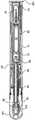
도 1은 본 발명을 포함하는 약물 전달 장치의 분해도이다.
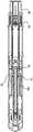
도 2는 도 1의 장치의 단면도이다.
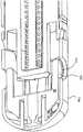
도 3 내지 도 9는 도 1의 장치에 포함된 구성요소의 상세도이다.
도 10 내지 도 16은 도 1의 장치의 기능 상태의 일부의 상세 단면도이다.1 is an exploded view of a drug delivery device incorporating the present invention.
Figure 2 is a cross-sectional view of the apparatus of Figure 1;
3 to 9 are detailed views of components included in the apparatus of Fig.
10 to 16 are detailed sectional views of a part of the functional state of the apparatus of Fig.
약물 전달 장치용 신호 지연 어셈블리의 일 실시예 및 약물 전달 장치의 일 실시예가 설명된다.One embodiment of a signal delay assembly for a drug delivery device and one embodiment of a drug delivery device is described.
도면에 도시된 약물 전달 장치용 신호 지연 어셈블리는 유체(140)를 수용하는 지연 암형 부재(138), 적어도 하나의 통로(128)를 가진 지연 수형 부재(124)(도 10), 및 본 예시적 실시형태에서 지연 수형 부재와 일체인 지연 유닛(96)(도 9)을 포함한다. 대안적 실시형태에서, 이 지연 유닛은 대신에 지연 암형 부재와 일체이고, 그에 따라 이 지연 암형 부재는 지연 유닛과 함께 이동가능하다. 지연 유닛(96)은 약물의 도즈가 완전히 전달되었음을 나타내는 적어도 하나의 피드백 신호를 생성하는 약물 전달 장치의 신호 발생 어셈블리에 착탈가능하게 연결된다. 수형 부재 및 암형 부재는, 수형 부재와 암형 부재 사이의 상대 이동이 상기 암형 부재로부터 적어도 하나의 통로를 통해 상기 유체의 이송을 유발시키도록, 서로를 향해 이동하도록 구성된다. 유체는 고도의 점성 유체이고, 적어도 하나의 통로는 유체의 이송이 느려지도록, 따라서 수형 부재와 암형 부재 사이의 이동, 즉 지연 암형 부재에 대한 지연 유닛 및 지연 수형 부재의 이동이 감속, 감쇄 또는 지연되도록 구성된다. 유체가 이송되었으면, 신호 발생 어셈블리는 지연 유닛으로부터 해제되어 신호 지연 어셈블리에 의해 지연된 신호를 생성한다.The signal delay assembly for a drug delivery device shown in the figures includes a delayed
이 신호 지연 어셈블리는 도 8의 지연 유닛(96)에 착탈가능하게 연결된 지지 요소(112)를 더 포함하여, 지연 암형 부재와 지연 수형 부재 사이의 상대 이동이 지연 유닛(96)과 지지 요소(112) 사이의 상대 이동을 유발시킴으로써, 적어도 하나의 피드백 신호를 발생하기 위해 지연 유닛으로부터 신호 발생 어셈블리의 해제를 유발시킨다. 또한, 상기 지연 유닛(96)은, 상기 지연 유닛이 상기 지지 요소 및 상기 신호 발생 어셈블리와 접촉하는 지연 위치로부터 상기 지연 유닛이 상기 지지 요소 및 상기 신호 발생 어셈블리로부터 단절되는 해제 위치로, 상기 지지 요소(112)에 대하여 이동가능하게 배치된다.This signal delay assembly further includes a
도면에 도시된 약물 전달 장치는 본 실시형태에서 조립을 위해 2개의 부분으로 분할된 하우징을 포함한다. 제 1 부분은 원위 단부(12) 및 근위 단부(14)를 갖는 대체로 튜브형인 기다란 근위 하우징(10)이고, 제 2 부분은 적합한 체결 요소에 의해 근위 하우징(10)의 원위 단부에 부착가능한 단부 캡의 형태를 가진 원위 하우징(134)이다. 상기 2개의 부분은 서로 고정되어 있음이 명백하다. 즉, 본 장치의 하우징은 하나의 구성요소로 보일 수 있다. 근위 하우징(10)에는 도 1 및 도 3의 윈도우 또는 개구(18)가 더 구비될 수 있고, 이를 통해 약물 용기(20)를 관찰할 수 있다. 각각의 개구(18)에는 도 3의 내측으로 향한 원주방향의 렛지(22)가 구비되어 있다. 이 개구(18)의 렛지(22)에는 링-형상의 지지 요소(24)가 더 부착되어 있다. 본 장치는 도 1의 대체로 튜브형인 약물 용기 홀더(26)를 더 포함한다. 이 약물 용기 홀더(26)는 개구(18)의 렛지(22)에 의해 대체로 반경 방향으로, 그리고 링-형상의 지지 요소(24)에 의해 대체로 종방향으로 지지되도록 배치되어 있다.The drug delivery device shown in the drawings includes a housing divided into two parts for assembly in this embodiment. The first portion is an elongate
약물 용기 홀더(26)는 약물 용기(20)를 수용하도록 되어 있고, 여기서 약물 용기(20)는 이 약물 용기(20)와 일체로 제작되거나 이 약물 용기(20)에 연결가능하게 제작되는 도 2의 약물 전달 부재(28)가 배치되는 근위 단부를 갖는다. 이 약물 전달 부재(28)는 도시된 실시형태에서 소위 강성 바늘 실드(needle shield) 또는 RNS인 약물 전달 부재 실드(30)에 의해 사용 전에 보호되는 것이 바람직하다. 그러나, 약물 전달 부재의 원하는 보호를 얻기 위해 다른 유형의 약물 전달 부재 실드가 사용될 수 있음을 이해해야 한다. 약물 용기(20)에는 도 2의 이동가능한 스토퍼(32)가 추가로 구비되어 있다.The
근위 하우징의 근위 단부에는 도 1의 중심 통로(34)가 구비되어 있고, 이 중심 통로를 통해 일반적으로 튜브형 약물 전달 부재 가드(36)가 연장된다(도 1 및 도 4). 약물 전달 부재 가드(36)는 하우징(10) 내에서 슬라이딩가능하게 배치된다. 약물 전달 부재 가드(36)는 근위 튜브형 부분(38) 및 이 튜브형 부분(38)으로부터 연장되는 2개의 원위방향으로 향한 암(40)을 포함한다. 약물 전달 부재 가드 스프링(42)은 약물 전달 부재 가드(36)의 원위방향으로 향한 원주방향의 벽 부분과 하우징의 근위방향으로 향한 원주방향의 표면 사이에 배치된다. 암(40)은 약물 용기 홀더(26)를 따라 슬라이딩가능하게 배치되고, 암(40) 내의 기다란 그루브(46)(도 4) 내에 끼워진 약물 용기 홀더(26)의 외면 상의 기다란 렛지에 의해 안내된다. 암(40)의 원위 단부에는 내측으로 향한 돌출부(48)가 배치되어 있다(도 4). 이 돌출부는 도 4 및 도 5의 로테이터(50)와 작동가능하게 상호작용하도록 배치되고, 결국 약물 용기(20)의 원위방향에 위치된다.The proximal end of the proximal housing is provided with the
로테이터(50)는 대체로 튜브형 형상을 가지며, 후술되는 바와 같이 약물 전달 부재 가드(36)의 돌출부(48)와 협동하도록 되어 있는 가이드 리지(guide ridge; 52)를 구비하고, 여기서 가이드 리지의 일부의 구간(52i)은 본 장치의 종방향에 대해 경사를 이룬다(도 5). 로테이터(50)는 가이드 리지(52)에 인접하여 위치된 대체로 반경방향으로 가요성인 텅(tongue; 56) 상에 배치된 쐐기-형상의 돌출부(54)를 더 구비하고, 이 쐐기-형상의 돌출부(54)는 후술되는 바와 같이 본 장치의 사용 완료 후에 약물 전달 부재 가드(36)를 로킹시키기 위한 것이다.The
로테이터(50)에는 또한 홀딩 유닛(58)이 작동가능하게 배치된다. 도 6 및 도 8의 홀딩 유닛(58)은 로테이터(50)의 내경보다 약간 작은 직경을 가진, 그리고 도 6의 중심 통로(61)를 구비한 근위 튜브형 제 1 구간(60)을 포함한다. 이것은 근위 하우징(10) 내에 끼워져서 이 근위 하우징(10)의 원위 부분에 부착되도록 된 제 2 구간(62)을 더 포함한다. 제 1 구간(60)은 도시된 실시형태에서 이 제 1 구간(60)의 근위 단부 표면으로부터 근위 방향으로 연장되는 아치형 요소의 형태인 홀딩 요소(64)를 더 구비한다. 이 홀딩 요소(64)는 도 2의 약물 용기 홀더(26) 내에 배치되었을 때 약물 용기(20)의 원위 단부 표면과 접촉하여 이를 가압하도록 되어 있다. 홀딩 유닛은 하우징에 고정적으로 연결되도록 구성된다.The rotator (50) is also operatively disposed with a holding unit (58). The holding
또한, 제 1 구간(60)에는 대체로 반경 방향으로 가요성인 근위방향으로 연장되는 암(66)이 구비되어 있다. 이 암(66)의 자유 단부는, 후술되는 바와 같이, 로테이터(50)의 내면과 상호작용하도록 된 외측으로 연장된 돌출부(68)를 갖는다. 이러한 관점에서, 로테이터(50)는, 도 5b에 도시된 바와 같이, 지지면(70) 및 이 지지면(70)에 인접한 종방향으로 연장된 리세스(72)를 구비하고, 여기서 지지면(70) 및 리세스(72)는, 후술되는 바와 같이, 외측으로 연장된 돌출부(68)와 상호작용한다. 또한, 암(66)의 자유 단부에는 내측으로 연장된 돌출부(74)가 구비되고, 이 돌출부(74)는 중심 통로(61) 내로 연장되고, 도 7의 플런저 로드(78) 상의 리세스(76)와 상호작용하기 위한 것이고, 이 플런저 로드(78)는 홀딩 유닛(58)의 중심 통로의 내부에 설치되도록 되어 있다. 이러한 관점에서, 플런저 로드(78)의 직경은 중심 통로(61)의 직경보다 다소 작다.In addition, the
신호 발생 어셈블리는 신호 발생 부재(84) 및 힘 요소를 포함한다(도 7). 이 힘 요소(80)는 상기 신호 발생 부재 및 플런저 로드(78) 사이에 장력이 가해진 상태로 배치되고(도 2, 도 11a 내지 도 12b), 후술되는 바와 같이 플런저 로드 및 신호 발생 부재를 이동시키도록 구성된다.The signal generating assembly includes a
도 2, 도 7 및 도 11a 내지 도 12b에 도시된 바와 같이, 힘 요소(80)는 중공 플런저 로드(78)의 공동 내부에 배치된 압축 스프링이고, 신호 발생 부재(84)는 베이스(86) 및 2개의 암(88)을 가진 대체로 U자형인 요소이다. 이 힘 요소는 그 근위 단부가 플런저 로드(78)의 단부 벽(82)과 접촉하고, 원위 단부가 신호 발생 부재(84)의 베이스(86)와 접촉하여 위치된다(도 2, 도 7 및 도 11a 내지 도 12b). 신호 발생 부재(84)의 암(88)은 플런저 로드(78)의 외면을 따라, 그리고 이 플런저 로드(78)의 외면과 접촉하여 근위 방향을 향하고, 여기서 암(88)의 자유 단부는 대체로 반경방향 외측으로 향하는 렛지(90)를 구비한다. 이들 렛지(90)는 도 6의 홀딩 유닛(58)의 중심 통로(61)를 둘러싸는 근위방향으로 향한 표면(92)과 접촉되도록 배치된다. 도 7의 스프링 안내 로드(93)는 또한 힘 요소(80)의 좌굴(buckling)을 방지하기 위해 베이스(86)의 근위방향으로 향한 표면(92)에 배치되어 힘 요소(80) 내로 연장된다.2, 7 and 11A-12B, the
도 9 및 도 10에 도시된 바와 같이, 원위 하우징(134)은 지연 암형 부재(138)가 배치되어 있는 근위방향으로 향한 내면(136)을 포함한다. 이 지연 암형 부재(138)는 튜브형 형상을 갖고, 원위 하우징(134)의 근위방향으로 향한 내면(136)으로부터 근위 방향을 향해 연장된다. 대안적 실시형태에서, 지연 수형 부재는 근위방향으로 향한 표면(136)에 배치되고, 지연 암형 부재는 지연 유닛(96)에 배치된다.As shown in Figures 9 and 10, the
도 8 및 도 9에 도시된 바와 같이, 지연 유닛(96)은 가요성 암(100)을 포함하고, 각각의 암의 자유 단부는 내측으로 향한 렛지(102)를 구비한다. 대체로 근위방향으로 향한 암(100)은 대체로 반경 방향으로 가요성이고, 지연 유닛의 본체(98)에 배치된다. 렛지(102)는 홀딩 유닛(58)의 원위 단부(12)에서 대체로 튜브형인 포스트(106) 상에 배치된 도 8의 종방향 슬롯(104) 내에 끼워맞춤된다. 이 포스트(106)는 단부 벽(108)을 구비하고, 이것의 기능은 후술된다. 대체로 튜브형인 지지 부재(110)는 포스트(106)와 동축으로 포스트(106)를 둘러싸도록 배치되고, 이 튜브형 지지 부재(110)는 근위 하우징(10)과 접촉하여 홀딩 유닛(58)을 지지하도록 배치된다.8 and 9, the
신호 지연 어셈블리의 지지 요소(112)는 홀딩 유닛에 배치된다. 도 8 및 도 10에 도시된 바와 같이, 지지 요소(112)는 홀딩 유닛, 더 구체적으로는 튜브형 지지 부재(110)와 일체이다. 즉, 이 지지 요소(112)는 반경방향의 내측으로 향한 렛지이고, 이것은 종방향으로 연장되고, 포스트(106)의 슬롯(103)에 대해 반경방향으로 대향하여 위치된다. 또한, 이 튜브형 지지 부재(110)는 컷아웃(cut-out; 114)을 구비하고, 이것의 기능은 후술한다. 도 10에 도시된 바와 같이, 본 장치의 초기의 비작동 위치에서, 암(100)은 지지 요소(112)와 접촉하여 대체로 반경방향의 외측 방향으로 이 암의 이동을 방지한다. 이 암(100)의 내측으로 향한 렛지(102)는 또한 신호 발생 부재(84)의 원위 단부(12), 더 구체적으로는 신호 발생 부재의 베이스(86)와 접촉한다.The
지연 유닛(96)은, 이 지연 유닛이 해제 위치에 있을 때, 상기 표시가 본 장치의 하우징을 통해 보일 수 있도록 시각적 표시(120)를 더 포함한다. 도 8에 도시된 바와 같이, 지연 유닛(96)의 본체(98)는 외측을 향한 만곡면을 가진 요소(116)를 더 구비한다. 이 요소(116)는 지지 부재(110)의 컷아웃(114)과 동일한 반경방향 위치에 대체로 위치된다. 만곡 요소(116)의 표면은 심볼 및/또는 특정의 컬러 표시와 같은 시각적 표시(120)를 구비하고, 이것의 기능은 후술한다. 또한, 본체(98)는 대체로 반경방향의 내측으로 향한 브릿지를 구비하고, 여기서 지연 수형 부재(124)가 부착되어 원위 방향으로 연장되어 있다. 이 지연 수형 부재(124)는 그 원위 단부에 통로(128)가 배치된 단부 벽(126)을 구비한다. 그 원위 단부에, 지연 수형 부재(124)의 외면은 탄성 O링(132)이 끼워맞춤될 수 있는 원주방향의 그루브(130)를 구비한다.The
지연 암형 부재(138)의 직경은 지연 수형 부재(124)의 탄성 O링(132)이 지연 암형 부재(138)의 내벽과 실링 접촉되도록 선택된다. 도 10에 도시된 바와 같이, 본 장치의 초기의 비작동 위치에서, 지연 수형 부재(124)의 단부 벽(126)과 원위 하우징(134)의 근위 표면(136) 사이에는 특정의 거리가 있다. 이 원위 하우징(134)은 지연 유닛(96) 상의 시각적 표시(120)와 정렬될 수 있는 도 9의 개구 또는 윈도우(141)를 더 구비하고, 이것의 기능은 후술한다.The diameter of the delayed
마지막으로, 본 약물 전달 장치는 이것의 근위 단부에 연결가능한 도 1 및 도 2의 보호 캡(142)을 구비한다. 이 보호 캡(142)은 튜브형 부분(144)으로 약물 전달 부재 가드(36) 내로 연장되고, 약물 전달 부재 실드(30)를 둘러싼다. 이 튜브형 부분(144)의 내면은 약물 전달 부재 실드(30)를 파지할 수 있는 그립(grip) 요소(146)를 구비한다.Finally, the drug delivery device has a
약물 전달 장치와 함께 신호 지연 어셈블리는 다음과 같이 기능하도록 되어 있다. 약물 용기(20)는 약물 용기 홀더(26) 내에 적재되어 본 장치의 하우징 내에 설치된다. 힘 요소(80)는 도 2에 도시된 바와 같이 플런저 로드(78)의 단부 벽(82)과 신호 발생 부재(84)의 베이스(86) 사이에서 장력이 가해져 있다. 이 플런저 로드(78)는 플런저 로드(78)의 리세스(76) 내에 배치된 암(66)의 돌출부(74)에 의해 홀딩 유닛(58)에 대해 정위치에 유지된다. 또한, 암(66)은 이 암(66)의 외측으로 향한 돌출부(68)가 로테이터(50)의 지지면(70)과 접촉하여 반경 방향의 외측으로 이동되는 것이 방지된다. 따라서, 힘 요소는 프리텐셔닝(pre-tensioning)된 상태로 유지된다.The signal delay assembly with the drug delivery device is designed to function as follows. The
또한, 신호 발생 부재(84)는 도 6의 홀딩 유닛(58)의 표면(92) 상에 안착된 렛지(90)로 인해 힘 요소(80)의 힘에 의해 원위 방향으로 이동되는 것이 방지된다. 신호 발생 부재(84)의 암(88)은 또한, 도 11b에 도시된 바와 같이, 플런저 로드(78)가 암(88)의 내면과 접촉함으로써 대체로 반경 방향으로 이동되는 것이 방지된다. 또한, 지연 유닛(96)의 암(100)의 렛지(102)는 신호 발생 부재(84)의 베이스(86)의 원위방향으로 향한 표면과 접촉하고, 암(100)은, 도 11b에 도시된 바와 같이, 지지 요소(112)에 의해 대체로 반경 방향으로 이동되는 것이 방지된다.The
사용자에게 전달될 때, 약물 전달 장치의 근위 단부는 그 근위 단부에 보호 캡(142)을 구비한다. 본 장치가 사용될 때, 보호 캡(142)은 근위 방향으로 당김으로써 제거된다. 이로 인해 그립 요소(146)는 약물 전달 부재 실드(30)를 파지하여 약물 전달 부재(28)로부터 제거한다. 약물 전달 부재 가드(36)는 자신의 최근위 위치로 도 11의 약물 전달 부재 가드 스프링(42)에 의해 편향된다.When delivered to the user, the proximal end of the drug delivery device has a
사용자가 도즈 전달 부위에 대해 약물 전달 부재 가드(36)의 근위 단부를 가압하고, 주사 바늘이 약물 전달 부재(28)로서 사용될 때, 사용자의 피부의 침투가 수행된다. 약물 전달 부재 가드(36)는 하우징에 대해 원위 방향으로 이동한다. 다음에 이로 인해 약물 전달 부재 가드(36)의 돌출부(48)는 돌출부가 경사진 구간(52i)과 접촉하도록 로테이터의 가이드 리지(52)를 따라 이동되고, 이로 인해 로테이터(50)는 본 장치의 종축선을 중심으로 회전된다.When the user presses the proximal end of the drug
로테이터(50)의 회전으로 인해 홀딩 유닛(58)의 외측으로 연장된 돌출부(68)는 로테이터(50)의 지지면(70)과의 접촉으로부터 벗어나서 그 리세스(72) 내로 이동하게 된다. 이제 홀딩 유닛(58)의 암(66)은 외측으로 자유롭게 굴곡됨으로써 암(66)의 내측으로 향한 돌출부(74)는 플런저 로드(78)의 리세스(76)와의 접촉으로부터 벗어나도록 이동된다.The
이제 플런저 로드(78)는 힘 요소(80)의 힘으로 인해 근위 방향으로 자유롭게 이동하고, 여기서 플런저 로드(78)의 근위 단부는 약물 용기(20)의 내부의 스토퍼(32) 상에 작용하여 근위 방향으로 이동시키므로 약물의 도즈는, 도 12에 도시된 바와 같이, 약물 전달 부재(28)를 통해 토출된다.The
허용오차에 따라, 스토퍼(32)가 플런저 로드(78)에 의해 약물 용기(20) 내의 근위 단부 또는 거의 근위 단부로 이동된 경우에, 플런저 로드(78)는, 도 13에 도시된 바와 같이, 신호 발생 부재(84)의 암(88)과의 접촉으로부터 벗어나도록 이동된다. 따라서, 신호 발생 부재(84)의 암(88)은 내측으로 자유롭게 굴곡될 수 있으므로 렛지(90)는 홀딩 유닛(58)의 표면과의 접촉으로부터 벗어나도록 이동될 수 있고, 힘 요소(80)의 잔류하는 힘으로 인해, 신호 발생 부재(84)는 원위방향으로 향한 힘(F)으로 도 10의 신호 지연 어셈블리의 지연 유닛(96)의 암(100)의 렛지(90) 상에 가압된다. 동시에, 힘 요소(80)는 근위방향으로 향한 힘(-F)으로 근위 방향으로 플런저 로드를 계속적으로 압박한다.When the
지연 유닛(96)은, 가요성 암(100)이 지지 요소와 접촉하는, 그리고 내측으로 향한 렛지(102)가 신호 발생 부재(84)의 베이스(86)와 접촉하는 지연 위치로부터 가요성 암(100)이 지지 요소로부터 단절되는, 그리고 도 14에 도시된 바와 같이 지지 요소에 대해 가요성 암의 반경방향 이동에 의해 신호 발생 부재(84)의 베이스(86)와의 접촉으로부터 벗어나도록 이동되는 해제 위치로 힘(F)에 의해 지지 요소(112)에 대해 종방향으로 이동된다. 따라서, 본 실시형태에서, 지연 수형 부재(124)도 또한 지연 암형 부재(138)의 내부에서 원위 방향으로 이동되고, 그 내부에 수용된 유체(140) 상에 압력을 가한다. 유체 상에 가해지는 압력으로 인해 유체는 중심 통로(128)를 통과하며, 이 통로가 좁고, 유체는 높은 점성을 가지므로, 신호 발생 부재(84) 및 지연 유닛(96)의 양자 모두의 원위 방향으로의 이동은 감쇄/둔화된다. 신호 발생 부재(84)의 느린 이동 중에, 스토퍼(32)는 그 단부 위치까지 근위방향으로 가압 또는 이동되어 주입 시퀀스를 완료한다.The
지연 유닛(96)이 홀딩 유닛(58)에 대해 특정의 위치에 도달하고, 지연 수형 부재(124)의 단부 벽(126)이 원위 하우징(134)의 근위 표면(136)에 거의 도달되면, 암(100)은, 도 14에 도시된 바와 같이, 지지 요소(112)와의 접촉으로부터 벗어나도록 이동됨으로써 암(100)은 대체로 반경 방향의 외측으로 굴곡된다(도 15). 도 14에 도시된 바와 같이, 신호 발생 부재(84)의 방출점과 홀딩 유닛(58)의 단부 벽(108)의 근위방향으로 향한 표면 사이에는 사전결정된 거리(d)가 설계되어 있고, 이것은 상대적으로 고정된, 즉 신호 발생 부재(84)의 이동에 대해 종방향으로 고정된 표면이다.When the
따라서, 이 신호 발생 부재(84)는 거리(d)를 따라 힘 요소의 힘으로 인해 자유롭게 이동 및 가속될 수 있다. 상기 신호 발생 부재의 원위 이동은 상기 적어도 하나의 피드백 신호가 생성되도록 상기 신호 발생 부재와 단부 벽(108) 사이의 상호작용을 유발한다. 이 상호작용 청각적 및/또는 촉각적 충격이다. 이 청각적 및/또는 촉각적 충격은, 도 15에 도시된 바와 같이, 신호 발생 부재(84)가 포스트(106)의 단부 벽(108)을 타격할 때 발생된다. 이 충격은 청각적 신호 뿐만 아니라 촉각적 신호를 생성하고, 이 신호는 사용자에게 주입 시퀀스가 종료되었고, 도즈 전달 부위로부터 본 장치를 제거하는 것이 안전하다는 것을 알려준다. 또한, 지연 유닛(96)은 설명된 바와 같이 하우징에 대해 원위 방향으로 이동되었기 때문에, 지연 유닛(96)의 요소(116)의 시각적 표시(120)는 원위 하우징(134)을 관통하여 볼 수 있는 윈도우(141)와 정렬되도록 원위방향으로 이동되었고(도 16), 이것 또한 사용자에게 주입 시퀀스가 종료되었고, 본 장치를 제거하는 것이 안전하다는 것을 알려 준다. 이 시각적 표시는 나중에 본 장치가 소비되어 폐기되어야 함을 나타내기 위해 사용될 수 있다. 이러한 관점에서, 이 시각적 표시는 명확하게 볼 수 있는 밝은 색일 수 있다.Thus, the
사용자가 전달 부위로부터 본 장치를 제거함에 따라, 약물 전달 부재 가드(36)는 약물 전달 부재 가드 스프링(42)에 의해 편향된 하우징(10)에 대해 근위 방향으로 이동된다. 결국 이것으로 인해 암(40)의 돌출부(48)는 로테이터(50)의 가이드 리지(52)를 따라 이동하게 되고, 그 결과 이 돌출부(48)는 텅(56)의 굴곡 작용으로 인해 쐐기-형상의 돌출부(54)를 통과하게 된다. 이 돌출부(48)의 통과로 인해 약물 전달 부재 가드(36)는 자신의 연장된 위치에 로킹됨으로써, 약물 전달 부재와의 의도하지 않은 접촉 및 가능한 상해가 방지된다. 이제 본 장치는 안전하게 폐기될 수 있다.As the user removes the device from the delivery site, the drug
대안적 실시형태(도시되지 않음)에서, 지연 암형 부재는 지연 유닛(96)과 일체이고(또는 지연 유닛(96)에 부착되고), 지연 수형 부재는 원위 하우징(134)의 근위방향으로 향한 내면(136)에 배치된다.In an alternative embodiment (not shown), the delayed female member is integral with delay unit 96 (or attached to delay unit 96) and the delayed male member is coupled to a proximal-facing
위에서 설명되고, 도면에 도시된 실시형태는 단지 본 발명의 비제한적 실시예로서 간주되어야 하며, 특허 청구항의 범위 내에서 많은 방식으로 개조될 수 있음을 이해해야 한다.It is to be understood that the embodiments described above and illustrated in the drawings are only to be considered as non-limiting embodiments of the invention and may be modified in many ways within the scope of the patent claims.
Claims (14)
Translated fromKorean상기 어셈블리는,
유체를 수용하는 지연 암형(delay male) 부재,
적어도 하나의 통로를 가진 지연 수형 부재, 및
상기 지연 암형 부재 또는 상기 지연 수형 부재에 연결된 지연 유닛(96)을 포함하고,
상기 지연 수형 부재 및 상기 지연 암형 부재 사이의 서로를 향한 상대 이동은 상기 이동을 둔화시키기 위해 상기 지연 암형 부재로부터 상기 적어도 하나의 통로를 통해 상기 유체의 이동을 유발하는, 신호 지연 어셈블리에 있어서,
상기 지연 유닛은 적어도 하나의 피드백 신호를 지연시키기 위한 신호 발생 어셈블리에 착탈가능하게 연결되고,
상기 신호 지연 어셈블리는 지연 유닛(96)에 착탈가능하게 연결된 지지 요소(112)를 더 포함하고, 상기 지연 암형 부재와 상기 지연 수형 부재 사이의 상대 이동은 상기 지연 유닛(96)과 상기 지지 요소(112) 사이의 상대 이동을 유발하여, 상기 신호 발생 어셈블리가 상기 지연 유닛으로부터 해제되게 해서 상기 적어도 하나의 피드백 신호를 생성하고,
상기 지연 유닛(96)은, 상기 지연 유닛이 상기 지지 요소 및 상기 신호 발생 어셈블리와 접촉하는 지연 위치로부터 상기 지연 유닛이 상기 지지 요소 및 상기 신호 발생 어셈블리의 양자 모두로부터 단절되는 해제 위치로, 상기 지지 요소(112)에 대하여 이동가능하게 배치되고,
상기 신호 발생 어셈블리는 신호 발생 부재(84) 및 힘 요소(80)를 포함하고, 상기 힘 요소(80)는 상기 약물 전달 장치의 플런저 로드(78) 및 상기 신호 발생 부재를 이동시키기 위해 상기 신호 발생 부재와 상기 플런저 로드 사이에 장력이 가해진 상태로 배치되고,
상기 신호 발생 부재는 상기 약물 전달 장치의 홀딩 유닛(58)에 착탈가능하게 연결되고, 상기 홀딩 유닛에 대하여 상기 플런저 로드의 사전결정된 근위의 종방향 이동은 상기 신호 발생 부재의 해제를 허용하여 상기 힘 요소가 상기 신호 발생 부재를 상기 홀딩 유닛에 대하여 원위로 이동시키도록 가압하고,
상기 지연 유닛(96)은, 상기 신호 발생 부재와 접촉하여 상기 신호 발생 부재의 이동이 상기 지연 위치로부터 상기 해제 위치로의 상기 지연 유닛의 이동을 유발하게 하는 것을 특징으로 하는
신호 지연 어셈블리.A signal delay assembly for a drug delivery device,
The assembly includes:
A delay male member for receiving the fluid,
A delay element having at least one passage, and
And a delay unit (96) coupled to the delayed female member or the delayed female member,
Relative movement of the delayed female member and the delayed female member toward each other causes movement of the fluid through the at least one passage from the delayed female member to slow the movement,
Wherein the delay unit is detachably connected to a signal generation assembly for delaying at least one feedback signal,
The delay assembly further comprises a support element (112) detachably connected to the delay unit (96), wherein a relative movement between the delayed female member and the delay element is achieved by the delay unit (96) and the support element 112) to cause the signal generating assembly to be released from the delay unit to generate the at least one feedback signal,
The delay unit (96) is configured to switch from a delayed position in which the delay unit contacts the support element and the signal generation assembly to a release position in which the delay unit is disconnected from both the support element and the signal generation assembly, Is disposed movably relative to the element (112)
Wherein the signal generating assembly includes a signal generating member and a force component and wherein the force component comprises a signal generating member for moving the plunger rod and the signal generating member of the drug delivery device, Wherein a tension is applied between the member and the plunger rod,
Wherein the signal generating member is removably connected to a holding unit (58) of the drug delivery device, and wherein a predetermined proximal longitudinal movement of the plunger rod relative to the holding unit allows release of the signal generating member An element urges the signal generating member to move over the circle with respect to the holding unit,
Characterized in that said delay unit (96) is in contact with said signal generating member such that movement of said signal generating member causes movement of said delay unit from said delay position to said release position
Signal delay assembly.
상기 지연 유닛은 가요성 암(100)을 포함하고, 상기 가요성 암의 자유 단부에는 내측으로 향한 렛지(ledge; 102)가 배치된 것을 특징으로 하는
신호 지연 어셈블리.The method according to claim 1,
Characterized in that the delay unit comprises a flexible arm (100) and an inwardly directed ledge (102) is arranged at the free end of the flexible arm
Signal delay assembly.
상기 지연 유닛은, 상기 가요성 암(100)이 상기 지지 요소와 접촉하는, 그리고 상기 내측으로 향한 렛지(102)가 상기 신호 발생 어셈블리와 접촉하는 지연 위치로부터 상기 가요성 암(100)이 상기 지지 요소로부터 단절되는, 그리고 상기 내측으로 향한 렛지(102)가 상기 지지 요소에 대한 상기 가요성 암의 반경방향 이동에 의해 상기 신호 발생 어셈블리로부터 단절되는 해제 위치로, 상기 지지 요소(112)에 대하여 종방향으로 이동가능한 것을 특징으로 하는
신호 지연 어셈블리.5. The method of claim 4,
The delay unit is configured to move the flexible arm (100) from the retard position where the flexible arm (100) contacts the support element and the inwardly directed ledge (102) To the releasing position, wherein the inward ledge (102) is disconnected from the element and is disconnected from the signal generating assembly by radial movement of the flexible arm relative to the supporting element, And is movable in a direction
Signal delay assembly.
상기 해제 위치에서 상기 지연 유닛은 상기 지지 요소 및 상기 신호 발생 부재의 모두로부터 단절되고, 이에 따라 상기 신호 발생 부재는 상기 힘 요소에 의해 상기 지지 요소 및 상기 지연 유닛에 대하여 원위로 가압되는 것을 특징으로 하는
신호 지연 어셈블리.The method according to claim 1,
Wherein said delay unit is disconnected from both said support element and said signal generating member such that said signal generating member is urged against said support element and said delay unit by said force element, doing
Signal delay assembly.
상기 신호 발생 부재의 원위 이동은 상기 적어도 하나의 피드백 신호가 생성되도록 상기 신호 발생 부재와 상기 홀딩 유닛(58)의 단부 벽(108) 사이의 상호작용을 유발하는 것을 특징으로 하는
신호 지연 어셈블리.10. The method of claim 9,
Wherein the distal movement of the signal generating member causes an interaction between the signal generating member and the end wall (108) of the holding unit (58) such that the at least one feedback signal is generated
Signal delay assembly.
상기 상호작용은 청각적 및/또는 촉각적 충격인 것을 특징으로 하는
신호 지연 어셈블리.11. The method of claim 10,
Characterized in that said interaction is an auditory and / or tactile impulse
Signal delay assembly.
상기 지연 유닛(96)은 시각적 표시를 포함하여, 상기 지연 유닛이 상기 해제 위치에 있을 때, 상기 시각적 표시가 사용자에게 보일 수 있는 것을 특징으로 하는
신호 지연 어셈블리.The method according to claim 1,
Wherein the delay unit (96) includes a visual indication that when the delay unit is in the released position, the visual indication may be visible to the user
Signal delay assembly.
상기 유체는 고도의 점성 유체인 것을 특징으로 하는
신호 지연 어셈블리.The method according to claim 1,
Characterized in that the fluid is a highly viscous fluid
Signal delay assembly.
약물 전달 장치.A signal delay assembly according to any one of claims 1, 4, 5 and 9 to 13,
Drug delivery device.
Applications Claiming Priority (3)
| Application Number | Priority Date | Filing Date | Title |
|---|---|---|---|
| SE1451017-6 | 2014-09-01 | ||
| SE1451017 | 2014-09-01 | ||
| PCT/EP2015/068951WO2016034407A2 (en) | 2014-09-01 | 2015-08-18 | Signal delaying assembly for a medicament delivery device |
Publications (2)
| Publication Number | Publication Date |
|---|---|
| KR20170048508A KR20170048508A (en) | 2017-05-08 |
| KR101960778B1true KR101960778B1 (en) | 2019-03-21 |
Family
ID=54064288
Family Applications (1)
| Application Number | Title | Priority Date | Filing Date |
|---|---|---|---|
| KR1020177008774AActiveKR101960778B1 (en) | 2014-09-01 | 2015-08-18 | Signal delaying assembly for a medicament delivery device |
Country Status (7)
| Country | Link |
|---|---|
| US (1) | US10384009B2 (en) |
| EP (1) | EP3188777B1 (en) |
| JP (1) | JP6452806B2 (en) |
| KR (1) | KR101960778B1 (en) |
| CN (1) | CN107530495B (en) |
| TW (1) | TWI586395B (en) |
| WO (1) | WO2016034407A2 (en) |
Families Citing this family (25)
| Publication number | Priority date | Publication date | Assignee | Title |
|---|---|---|---|---|
| EP2399635A1 (en) | 2010-06-28 | 2011-12-28 | Sanofi-Aventis Deutschland GmbH | Auto-injector |
| DK3452146T3 (en) | 2016-05-06 | 2024-05-27 | Shl Medical Ag | DRIVE UNIT FOR A MEDICATION DELIVERY DEVICE |
| US11324895B2 (en) | 2016-11-01 | 2022-05-10 | Sanofi-Aventis Deutschland Gmbh | Feedback mechanism for an injection device |
| EP3534990B1 (en) | 2016-11-01 | 2025-03-19 | Sanofi-Aventis Deutschland GmbH | Feedback mechanism for an injection device |
| EP3326671A1 (en) | 2016-11-29 | 2018-05-30 | Carebay Europe Ltd. | Activation assembly for a medicament delivery device |
| CH712774A2 (en)* | 2017-11-21 | 2018-01-31 | Tecpharma Licensing Ag | Delay device for a medical delivery device. |
| EP3492124A1 (en)* | 2017-12-01 | 2019-06-05 | Sanofi | Injector device |
| CN112188907A (en) | 2018-05-24 | 2021-01-05 | 诺华股份有限公司 | Automatic drug delivery device |
| JP7390388B2 (en)* | 2019-02-26 | 2023-12-01 | ベクトン ディキンソン フランス | Automatic syringe with audible indicator |
| EP4072625B1 (en)* | 2019-12-09 | 2023-08-16 | SHL Medical AG | Assembly, cassette and medicament delivery device |
| USD955565S1 (en)* | 2020-05-29 | 2022-06-21 | Medivena Sp. Z O.O. | Needle-based device with a safety mechanism |
| WO2022029097A1 (en)* | 2020-08-07 | 2022-02-10 | Sanofi | Arrangement for a drug delivery device |
| EP4192547A1 (en)* | 2020-08-07 | 2023-06-14 | Sanofi | Drive arrangement for a drug delivery device |
| TW202237207A (en) | 2020-12-31 | 2022-10-01 | 美商再生元醫藥公司 | Auto-injector and related methods of use |
| EP4284469A1 (en)* | 2021-02-24 | 2023-12-06 | TERUMO Kabushiki Kaisha | Medication administration device |
| WO2023001540A1 (en)* | 2021-07-22 | 2023-01-26 | Shl Medical Ag | A subassembly of a medicament delivery device |
| EP4419175A1 (en)* | 2021-10-19 | 2024-08-28 | SHL Medical AG | Automatic feedback mechanism for a medicament delivery device |
| US20250114532A1 (en)* | 2022-01-21 | 2025-04-10 | Shl Medical Ag | Sub-assembly for a medicament delivery device |
| EP4469111A1 (en)* | 2022-01-25 | 2024-12-04 | Regeneron Pharmaceuticals, Inc. | Drug delivery device safety system |
| US20250108170A1 (en)* | 2022-01-28 | 2025-04-03 | Shl Medical Ag | Sub-assembly for a medicament delivery device |
| EP4507759A1 (en) | 2022-04-11 | 2025-02-19 | Becton Dickinson France | Autoinjector for automatic injection of a product into an injection site |
| EP4619060A1 (en)* | 2022-11-15 | 2025-09-24 | Becton Dickinson France | Autoinjector |
| WO2024223329A1 (en)* | 2023-04-27 | 2024-10-31 | Shl Medical Ag | Medicament delivery device and medicament delivery assembly |
| WO2025021934A1 (en)* | 2023-07-27 | 2025-01-30 | Shl Medical Ag | Medicament delivery device |
| US12420017B1 (en)* | 2025-02-26 | 2025-09-23 | Genzyme Corporation | Damping device for a medicament delivery device |
Citations (3)
| Publication number | Priority date | Publication date | Assignee | Title |
|---|---|---|---|---|
| WO2011123024A1 (en) | 2010-03-31 | 2011-10-06 | Shl Group Ab | Medicament delivery device comprising feedback signalling means |
| US20130218093A1 (en) | 2010-08-27 | 2013-08-22 | Novo Nordisk A/S | Medical Injection Device |
| WO2013178512A1 (en)* | 2012-05-31 | 2013-12-05 | Carebay Europe Ltd | Medicament delivery device |
Family Cites Families (16)
| Publication number | Priority date | Publication date | Assignee | Title |
|---|---|---|---|---|
| US4561856A (en)* | 1983-08-18 | 1985-12-31 | Cochran Ulrich D | Infusion pump |
| GB2414775B (en) | 2004-05-28 | 2008-05-21 | Cilag Ag Int | Releasable coupling and injection device |
| GB2414404B (en)* | 2004-05-28 | 2009-06-03 | Cilag Ag Int | Injection device |
| US7119593B2 (en) | 2005-02-08 | 2006-10-10 | International Business Machines Corporation | Delayed signal generation circuits and methods |
| FR2905273B1 (en)* | 2006-09-06 | 2009-04-03 | Becton Dickinson France Soc Pa | AUTOMATIC INJECTION DEVICE WITH TIMING MEANS. |
| AU2009309895B2 (en)* | 2008-10-29 | 2012-06-07 | Shl Group Ab | Injection device |
| JP5701889B2 (en) | 2009-10-08 | 2015-04-15 | エス・ホー・エル・グループ・アクチボラゲットShl Group Ab | Drug supply device |
| EP2361648A1 (en)* | 2010-02-18 | 2011-08-31 | Sanofi-Aventis Deutschland GmbH | Remover for a protective needle shield |
| ES2484266T3 (en)* | 2010-03-01 | 2014-08-11 | Eli Lilly And Company | Automatic injection device with delay mechanism including a double function thrust element |
| EP2364740A1 (en) | 2010-03-09 | 2011-09-14 | Sanofi-Aventis Deutschland GmbH | Arrangement for transferring a translation of a drive means to a plunger |
| EP2438939A1 (en)* | 2010-10-08 | 2012-04-11 | Sanofi-Aventis Deutschland GmbH | Arrangement for coupling a plunger to either a syringe or a stopper |
| US9468722B2 (en)* | 2011-11-25 | 2016-10-18 | Shl Group Ab | Medicament delivery device |
| HUE026766T2 (en) | 2012-09-05 | 2016-07-28 | Becton Dickinson France | Automatic injection device |
| KR101767793B1 (en)* | 2012-10-11 | 2017-08-11 | 케어베이 유럽 리미티드 | Automatic injection training device |
| EP3107605B1 (en)* | 2014-02-17 | 2018-09-26 | Carebay Europe Ltd. | Medicament delivery device with delivery finish signal delay |
| EP3151881B1 (en)* | 2014-06-05 | 2018-08-22 | Carebay Europe Ltd. | Medicament delivery device with delivery finish signal delay |
- 2015
- 2015-08-18KRKR1020177008774Apatent/KR101960778B1/enactiveActive
- 2015-08-18CNCN201580053756.5Apatent/CN107530495B/enactiveActive
- 2015-08-18WOPCT/EP2015/068951patent/WO2016034407A2/enactiveApplication Filing
- 2015-08-18JPJP2017511916Apatent/JP6452806B2/enactiveActive
- 2015-08-18EPEP15759669.3Apatent/EP3188777B1/enactiveActive
- 2015-08-18USUS15/507,673patent/US10384009B2/enactiveActive
- 2015-08-25TWTW104127693Apatent/TWI586395B/enactive
Patent Citations (3)
| Publication number | Priority date | Publication date | Assignee | Title |
|---|---|---|---|---|
| WO2011123024A1 (en) | 2010-03-31 | 2011-10-06 | Shl Group Ab | Medicament delivery device comprising feedback signalling means |
| US20130218093A1 (en) | 2010-08-27 | 2013-08-22 | Novo Nordisk A/S | Medical Injection Device |
| WO2013178512A1 (en)* | 2012-05-31 | 2013-12-05 | Carebay Europe Ltd | Medicament delivery device |
Also Published As
| Publication number | Publication date |
|---|---|
| WO2016034407A2 (en) | 2016-03-10 |
| TWI586395B (en) | 2017-06-11 |
| WO2016034407A3 (en) | 2017-07-27 |
| US20170368259A1 (en) | 2017-12-28 |
| TW201620565A (en) | 2016-06-16 |
| EP3188777A2 (en) | 2017-07-12 |
| EP3188777B1 (en) | 2020-07-01 |
| CN107530495A (en) | 2018-01-02 |
| JP2017528217A (en) | 2017-09-28 |
| US10384009B2 (en) | 2019-08-20 |
| JP6452806B2 (en) | 2019-01-16 |
| CN107530495B (en) | 2020-10-09 |
| KR20170048508A (en) | 2017-05-08 |
Similar Documents
| Publication | Publication Date | Title |
|---|---|---|
| KR101960778B1 (en) | Signal delaying assembly for a medicament delivery device | |
| JP6257601B2 (en) | Drug delivery device | |
| EP2362792B1 (en) | Autoinjector with audible indication of completed delivery | |
| EP2630981B1 (en) | Medicament delivery device | |
| US20160022908A1 (en) | Medicament delivery device | |
| EP3285832B1 (en) | Drive mechanism for an autoinjector | |
| TWI581815B (en) | Medicament delivery device | |
| GB2552340A (en) | Medicament delivery device | |
| KR20180015188A (en) | Drug delivery device |
Legal Events
| Date | Code | Title | Description |
|---|---|---|---|
| A201 | Request for examination | ||
| PA0105 | International application | Patent event date:20170330 Patent event code:PA01051R01D Comment text:International Patent Application | |
| PA0201 | Request for examination | ||
| PG1501 | Laying open of application | ||
| E902 | Notification of reason for refusal | ||
| PE0902 | Notice of grounds for rejection | Comment text:Notification of reason for refusal Patent event date:20180822 Patent event code:PE09021S01D | |
| E701 | Decision to grant or registration of patent right | ||
| PE0701 | Decision of registration | Patent event code:PE07011S01D Comment text:Decision to Grant Registration Patent event date:20181226 | |
| PN2301 | Change of applicant | Patent event date:20190307 Comment text:Notification of Change of Applicant Patent event code:PN23011R01D | |
| PR0701 | Registration of establishment | Comment text:Registration of Establishment Patent event date:20190315 Patent event code:PR07011E01D | |
| PR1002 | Payment of registration fee | Payment date:20190318 End annual number:3 Start annual number:1 | |
| PG1601 | Publication of registration | ||
| PR1001 | Payment of annual fee | Payment date:20220223 Start annual number:4 End annual number:4 | |
| PR1001 | Payment of annual fee | Payment date:20230223 Start annual number:5 End annual number:5 | |
| PR1001 | Payment of annual fee | Payment date:20250225 Start annual number:7 End annual number:7 |