KR101959774B1 - Surgical guide system for dental implant having external irrigation device - Google Patents
Surgical guide system for dental implant having external irrigation deviceDownload PDFInfo
- Publication number
- KR101959774B1 KR101959774B1KR1020180150313AKR20180150313AKR101959774B1KR 101959774 B1KR101959774 B1KR 101959774B1KR 1020180150313 AKR1020180150313 AKR 1020180150313AKR 20180150313 AKR20180150313 AKR 20180150313AKR 101959774 B1KR101959774 B1KR 101959774B1
- Authority
- KR
- South Korea
- Prior art keywords
- guide
- surge
- main receiving
- rubber tube
- receiving tube
- Prior art date
- Legal status (The legal status is an assumption and is not a legal conclusion. Google has not performed a legal analysis and makes no representation as to the accuracy of the status listed.)
- Expired - Fee Related
Links
Images


Classifications
- A—HUMAN NECESSITIES
- A61—MEDICAL OR VETERINARY SCIENCE; HYGIENE
- A61C—DENTISTRY; APPARATUS OR METHODS FOR ORAL OR DENTAL HYGIENE
- A61C8/00—Means to be fixed to the jaw-bone for consolidating natural teeth or for fixing dental prostheses thereon; Dental implants; Implanting tools
- A61C8/0089—Implanting tools or instruments
- A61C8/009—Implanting tools or instruments for selecting the right implanting element, e.g. templates
- A—HUMAN NECESSITIES
- A61—MEDICAL OR VETERINARY SCIENCE; HYGIENE
- A61B—DIAGNOSIS; SURGERY; IDENTIFICATION
- A61B17/00—Surgical instruments, devices or methods
- A61B17/16—Instruments for performing osteoclasis; Drills or chisels for bones; Trepans
- A61B17/17—Guides or aligning means for drills, mills, pins or wires
- A61B17/1739—Guides or aligning means for drills, mills, pins or wires specially adapted for particular parts of the body
- A61B17/176—Guides or aligning means for drills, mills, pins or wires specially adapted for particular parts of the body for the jaw
- A—HUMAN NECESSITIES
- A61—MEDICAL OR VETERINARY SCIENCE; HYGIENE
- A61C—DENTISTRY; APPARATUS OR METHODS FOR ORAL OR DENTAL HYGIENE
- A61C1/00—Dental machines for boring or cutting ; General features of dental machines or apparatus, e.g. hand-piece design
- A61C1/08—Machine parts specially adapted for dentistry
- A61C1/082—Positioning or guiding, e.g. of drills
- A61C1/084—Positioning or guiding, e.g. of drills of implanting tools
- A—HUMAN NECESSITIES
- A61—MEDICAL OR VETERINARY SCIENCE; HYGIENE
- A61C—DENTISTRY; APPARATUS OR METHODS FOR ORAL OR DENTAL HYGIENE
- A61C17/00—Devices for cleaning, polishing, rinsing or drying teeth, teeth cavities or prostheses; Saliva removers; Dental appliances for receiving spittle
- A61C17/02—Rinsing or air-blowing devices, e.g. using fluid jets or comprising liquid medication
- A—HUMAN NECESSITIES
- A61—MEDICAL OR VETERINARY SCIENCE; HYGIENE
- A61C—DENTISTRY; APPARATUS OR METHODS FOR ORAL OR DENTAL HYGIENE
- A61C8/00—Means to be fixed to the jaw-bone for consolidating natural teeth or for fixing dental prostheses thereon; Dental implants; Implanting tools
- A61C8/0089—Implanting tools or instruments
- A—HUMAN NECESSITIES
- A61—MEDICAL OR VETERINARY SCIENCE; HYGIENE
- A61B—DIAGNOSIS; SURGERY; IDENTIFICATION
- A61B17/00—Surgical instruments, devices or methods
- A61B17/16—Instruments for performing osteoclasis; Drills or chisels for bones; Trepans
- A61B17/1644—Instruments for performing osteoclasis; Drills or chisels for bones; Trepans using fluid other than turbine drive fluid
- A61B2017/1651—Instruments for performing osteoclasis; Drills or chisels for bones; Trepans using fluid other than turbine drive fluid for cooling
- A—HUMAN NECESSITIES
- A61—MEDICAL OR VETERINARY SCIENCE; HYGIENE
- A61B—DIAGNOSIS; SURGERY; IDENTIFICATION
- A61B2217/00—General characteristics of surgical instruments
- A61B2217/002—Auxiliary appliance
- A61B2217/007—Auxiliary appliance with irrigation system
Landscapes
- Health & Medical Sciences (AREA)
- Life Sciences & Earth Sciences (AREA)
- Dentistry (AREA)
- Oral & Maxillofacial Surgery (AREA)
- Animal Behavior & Ethology (AREA)
- General Health & Medical Sciences (AREA)
- Public Health (AREA)
- Veterinary Medicine (AREA)
- Epidemiology (AREA)
- Surgery (AREA)
- Orthopedic Medicine & Surgery (AREA)
- Nuclear Medicine, Radiotherapy & Molecular Imaging (AREA)
- Engineering & Computer Science (AREA)
- Biomedical Technology (AREA)
- Heart & Thoracic Surgery (AREA)
- Medical Informatics (AREA)
- Molecular Biology (AREA)
- Dental Tools And Instruments Or Auxiliary Dental Instruments (AREA)
Abstract
Translated fromKoreanDescription
Translated fromKorean본 발명은 치아 임플란트 시술시 사용하는 서지컬 가이드 시스템에 관한 것으로서, 좀더 상세하게는 서지컬 가이드를 사용하여 잇몸 뼈에 대해 드릴링 작업을 할 때 발생하는 열을 식히기 위한 외부 주수 장치를 구비하는 치아 임플란트 시술용 서지컬 가이드 시스템에 관한 것이다.BACKGROUND OF THE INVENTION 1. Field of the Invention [0001] The present invention relates to a surge guiding system for use in dental implant treatment, and more particularly, to a surge guiding system for use in a dental implant system including an external pouring apparatus for cooling heat generated when a drilling operation is performed on a gum bone using a surge- And more particularly to a surgical guide system for operation.
치아 임플란트(Dental Implant, 이하 간략히 "임플란트"라 함)는 인공 치아 또는 제3의 치아라고도 한다. 즉, 임플란트란 치아의 결손이 있는 부위나 치아를 뽑은 자리의 잇몸 뼈에 생체 적합성이 우수한 재질, 예를 들면 티타늄계 금속 재질로 만들어진 인공 치아를 심어서 자연치의 기능을 회복시켜주는 치과 치료 술식, 또는 인공 치아 자체를 지칭하는 것이다.A dental implant (hereinafter simply referred to as an "implant ") is also called an artificial tooth or a third tooth. That is, the implant is a dental treatment method that restores the function of a natural tooth by implanting a biocompatible material such as a titanium-based metal artificial tooth on a portion of a tooth having a defect or a gum bone of a tooth extracted from the tooth, Or an artificial tooth itself.
이러한 임플란트는 다양한 구조를 가지는데, 공지된 여러 문헌으로부터 확인할 수 있는 바와 같이, 기본적으로 픽스쳐(fixture)와 어버트먼트(abutment), 그리고 인공 크라운(crown)의 요소로 이루어진다. 픽스쳐는 생체 적합성이 우수한 재질의 나사형상으로 형성되어 치아가 상실된 치조골(잇몸 뼈)에 매식되어 골 융합되고, 어버트먼트는 그 상단에 저작(詛嚼)과 미용을 위한 인공 크라운이 장착되는 상부 구조체로서 하부의 픽스쳐와 나사결합 또는 억지끼움 방식으로 결합한다.These implants have a variety of structures, and basically consist of fixture, abutment, and artificial crown elements, as can be seen from various known documents. The fixture is formed into a screw shape of a material having excellent biocompatibility so that the bone is fused to the alveolar bone (gum bone) in which the teeth are lost, and the abutment is provided with an artificial crown for chewing and beauty As a structure, it is combined with screw fixture or interference fit in the lower fixture.
임플란트 시술은 드릴을 이용하여 치조골에 형성한 천공에 픽스쳐를 식립하여 수행되는데, 환자의 치아 상태나 임플란트 시술이 필요한 치아의 위치, 환자의 치조골의 상태 등 다양한 요인을 고려하여 임플란트의 식립 위치 및 깊이와 방향을 결정해야 하기 때문에 천공을 형성하는 드릴링 시술은 환자마다 각각 상이하다.Implantation is performed by placing a fixture on a perforation formed on the alveolar bone using a drill. The position and depth of the implant, taking into consideration various factors such as the patient's tooth condition, the position of the tooth requiring the implant treatment, And the direction of the drilling is to be determined, the drilling procedure for forming the perforation is different for each patient.
이처럼 환자마다 치조골의 드릴링 시술이 달라지기 때문에 초심자는 물론이거니와 경험자마저도 원하는 대로 정확히 치조골에 천공을 형성하는 것은 매우 어렵다. 치조골에 정확히 천공을 형성하지 못하면 픽스쳐의 식립 상태와 골 융합의 예후가 좋지 못하고, 이는 치아 임플란트 시술의 성공률을 낮추는 중요 요인이 된다.Because the drilling procedure of the alveolar bone is different for each patient, it is very difficult to form a hole in the alveolar bone precisely as desired even for the beginner and the experienced person. Failure to form the perforation in the alveolar bone results in poor fixture placement and prognosis of bone fusion, which is an important factor in lowering the success rate of the dental implant procedure.
이런 문제점을 해결하기 위해, 특허문헌 1과 같은 서지컬 가이드(surgical guide)라고 하는 보조 기구를 사용하는 방법이 근래에 점차 전파되고 있다. 서지컬 가이드는 기 설계된 형상으로의 성형이 용이한 합성수지 재질로 제조되며, 환자의 구강 내부에 고정된 상태에서 임플란트 시술 계획에 대응되는 드릴링 작업을 안내하는 안내공이 구비되어 있다.In order to solve such a problem, a method of using an auxiliary mechanism such as a surgical guide as in Patent Document 1 has been gradually spreading in recent years. The surgeon guide is made of a synthetic resin material that is easily molded into a designed shape and has a guide hole for guiding the drilling operation corresponding to the implant operation plan in a state fixed to the inside of the patient's mouth.
상기 안내공은 드릴링 작업의 천공 각도에 대응하도록 서지컬 가이드 상에 되어 관통 형성되어 있고, 이에 따라 안내공의 내주면에 임플란트용 드릴의 외주면이 회전 지지되어 드릴링 작업이 정확히 이루어지도록 안내하게 된다. 경우에 따라서, 안내공에는 임플란트 드릴의 지지 강도를 보강하고자 금속 재질의 원통형 슬리브가 장착되기도 한다.The guide hole is formed on the surge guide so as to correspond to the drilling angle of the drilling operation. Thus, the outer circumferential surface of the implant drill is rotatably supported on the inner circumferential surface of the guide hole to guide the drilling operation accurately. In some cases, a guide sleeve may be equipped with a cylindrical sleeve of a metal material to reinforce the support strength of the implant drill.
서지컬 가이드의 사용은 치아 임플란트 수술의 성공률 향상에 큰 효과를 가져왔지만, 임상 과정에서 한 가지 문제점이 나타났다. 이는 드릴링 과정 중의 치조골 변성에 관한 문제인데, 종래 서지컬 가이드를 사용하지 않을 때에는 수술 부위가 노출되어 있기 때문에 세정수를 직접 주수하여 드릴을 냉각하는데 아무 문제가 없었지만, 서지컬 가이드가 수술 부위를 감싸고 안내공으로는 드릴이 진입하기 때문에 서지컬 가이드 사용시 수술 부위에 주수하는 것이 곤란해졌다.The use of surge arresters has had a great effect on improving the success rate of dental implant surgery, but one problem has arisen in clinical practice. This is a problem related to denudation of the alveolar bone during the drilling process. When the surgeal guide is not used, there is no problem in cooling the drill by directly injecting the washing water because the surgical site is exposed. However, Since the drill is inserted into the guide ball, it is difficult to inject the surgical guide when using the sagittal guide.
드릴링을 하는 수술 부위를 적절히 냉각하지 못하면 치조골 조직에 열 변성이 일어나기 쉽고, 치조골 조직의 변성은 픽스쳐의 골 융합에 나쁜 영향을 미치게 된다. 이런 문제를 해결하기 위한 방안으로 드릴을 관통하거나 또는 드릴 외주면을 통해 주수하는 방법이 제안되기도 했지만, 충분한 압력의 세정수가 주수되기는 어렵기 때문에 큰 효과를 기대할 수 없었다.Failure to adequately cool the surgical site to drill is likely to cause thermal denaturation of the alveolar bone tissue and degeneration of the alveolar bone tissue will adversely affect the bone fusion of the fixture. In order to solve this problem, a method has been proposed in which a drill is pierced or poured through a drill outer circumferential surface, but a large effect can not be expected because it is difficult for a sufficient amount of wash water to be poured.
본 발명은 서지컬 가이드를 사용하여 치조골에 대해 드릴링 작업을 할 때에도 치아 식립 대상부에 발생하는 열을 효과적으로 냉각할 수 있는 치아 임플란트 시술용 서지컬 가이드 시스템을 제공하는데 그 목적이 있다.An object of the present invention is to provide a surge guiding system for dental implant treatment that can effectively cool the heat generated in a tooth placement part even when a drilling operation is performed on an alveolar bone using a surge guide.
본 발명은 치아 임플란트 시술용 서지컬 가이드 시스템에 관한 것으로서, 치아 임플란트 시술을 위한 드릴링 작업을 안내하기 위한 안내공을 구비하고, 피시술자의 구강 내부로부터 획득된 3차원 데이터를 기반으로 치아 식립 대상부를 감싸 고정되는 프로파일로 제조되는 서지컬 가이드;와, 상기 서지컬 가이드를 관통하여 장착되고, 일단은 상기 서지컬 가이드 밖으로 돌출되며, 타단은 상기 안내공을 우회하여 상기 치아 식립 대상부를 향하도록 연장된 주수용 튜브;와, 주수용 시린지 또는 세정수 팩으로 이루어진 세정수 공급원; 및 상기 주수용 튜브의 일단과 상기 세정수 공급원을 연결하는 고무 튜브;를 포함한다.The present invention relates to a surge guiding system for performing a dental implant, and includes a guide hole for guiding a drilling operation for a dental implant, and the tooth placement part is wrapped around the tooth based on three-dimensional data obtained from the inside of the mouth A surge guide mounted on the surge guide, one end protruding out of the surge guide, and the other end guiding the tooth to be placed, A rinse water supply source consisting of a main receiving syringe or a rinsing water pack; And a rubber tube connecting one end of the main receiving tube and the rinse water supply source.
본 발명의 일 실시형태에 따라서는, 상기 안내공에는 금속 재질의 슬리브가 장착되고, 상기 슬리브의 외주면과 내주면 사이에는 상기 치아 식립 대상부 쪽이 개방된 환형의 주수 공간이 형성되어 있으며, 상기 주수용 튜브의 타단은 상기 주수 공간과 연통되어 있다.According to one embodiment of the present invention, a sleeve made of a metal material is mounted on the guide hole, and an annular main water space in which the tooth to be placed is opened is formed between the outer peripheral surface and the inner peripheral surface of the sleeve, And the other end of the receiving tube communicates with the main water space.
그리고, 상기 주수용 튜브의 타단은 두 개 이상의 세정수 분사구를 형성할 수 있다.The other end of the main receiving tube may form two or more washing water jetting openings.
그리고, 상기 주수용 튜브의 일단은 절치 쪽으로 절곡되어 있을 수도 있다.One end of the main receiving tube may be bent toward the incisal side.
또한, 상기 주수용 튜브의 타단은 상기 일단으로부터 제1 가지와 제2 가지로 분기되고, 상기 제1 가지와 제2 가지는 각각 상기 치아 식립 대상부의 설측과 협측을 향하여 연장될 수도 있다.Further, the other end of the main receiving tube may be branched from the one end into the first branch and the second branch, and the first branch and the second branch may extend toward the lingual and buccal sides of the tooth placement target, respectively.
본 발명의 일 실시형태에 따라서는, 상기 서지컬 가이드 상에는 상기 고무 튜브를 일시적이고 탄력적으로 고정하는 고리가 구비할 수 있다.According to an embodiment of the present invention, a ring for temporarily and resiliently fixing the rubber tube may be provided on the surge guide.
또한, 상기 고무 튜브는, 상기 주수용 튜브의 일단에 연결되고 상기 고리에 고정되는 제1 고무 튜브와, 상기 제1 고무 튜브와 상기 세정수 공급원을 연결하는 제2 고무 튜브로 이루어지고, 상기 제1 고무 튜브 및 제2 고무 튜브는 연결 니플에 의해 상호 연결될 수 있다.The rubber tube may include a first rubber tube connected to one end of the main receiving tube and fixed to the loop and a second rubber tube connecting the first rubber tube and the washing water supply source, The first rubber tube and the second rubber tube may be interconnected by a connecting nipple.
그리고, 상기 주수용 튜브의 일단은 절치 영역에서 외부로 돌출되고, 상기 주수용 튜브의 타단은 상기 서지컬 가이드의 내부를 따라 상기 치아 식립 대상부로 연장되어 있을 수 있다.One end of the main receiving tube may protrude outward from the incised area, and the other end of the main receiving tube may extend to the tooth placing part along the inside of the surge guide.
또한, 본 발명의 실시형태에 따라서는, 상기 서지컬 가이드의 내부를 따라 상기 치아 식립 대상부로 연장된 주수용 튜브의 적어도 일부는 상기 서지컬 가이드의 내부에 형성된 통공으로 형성될 수도 있다.According to an embodiment of the present invention, at least a part of the main receiving tube extending to the tooth placing portion along the inside of the surge guide may be formed as a through hole formed in the inside of the surge guide.
상기와 같은 구성을 가진 본 발명의 치아 임플란트 시술용 서지컬 가이드 시스템은 서지컬 가이드를 관통하여 마련된 주수용 튜브를 통해 치아 식립 대상부에 직접 가압된 세정수를 주수함으로써 드릴링 작업시 발생하는 열을 효과적으로 냉각할 수 있다.The surge guiding system for dental implant treatment according to the present invention having the above-described configuration injects the washing water directly pressed to the tooth placing part through the main receiving tube provided through the surge guide, It can be effectively cooled.
또한, 사용자가 세정수 공급원으로 사용되는 주수용 시린지 또는 세정수 팩을 누르는 힘을 조절함으로써 주입되는 세정수의 압력을 손쉽게 조정할 수 있어 임플란트 시술 상황에 맞춰 적절한 냉각 효과를 얻을 수 있다.In addition, the pressure of the washing water to be injected can be easily adjusted by adjusting the pressing force of the main receiving syringe or the washing water pack used as the washing water supply source by the user, so that an appropriate cooling effect can be obtained in accordance with the implant treatment situation.
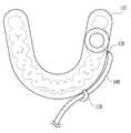
도 1은 본 발명에 따른 치아 임플란트 시술용 서지컬 가이드 시스템의 전체적인 구성을 도시한 도면.
도 2는 도 1의 "A-A" 선을 따라 절개한 단면도.
도 3은 주수 공간이 형성된 슬리브에 대해 주수용 튜브를 연결하는 실시형태에 대한 단면도.
도 4는 주수용 튜브에 대한 몇몇 실시형태를 도시한 도면.
도 5는 서지컬 가이드 상에 고무 튜브를 일시적으로 고정하는 고리가 구비된 실시형태를 도시한 도면.
도 6은 도 5의 고리를 이용하면서 고무 튜브를 두 부분으로 분할한 실시형태를 도시한 도면.
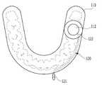
도 7은 주수용 튜브의 입구가 서지컬 가이드의 절치 영역에 돌출된 실시형태를 도시한 도면.BRIEF DESCRIPTION OF THE DRAWINGS Fig. 1 is a diagram showing the overall configuration of a surge guidance system for dental implant treatment according to the present invention; Fig.
2 is a cross-sectional view taken along the line "AA" in Fig.
Fig. 3 is a cross-sectional view of an embodiment connecting the main containment tube to a sleeve having a cavity formed therein; Fig.
Figure 4 shows some embodiments for a containment tube.
5 shows an embodiment with a ring temporarily securing a rubber tube on a surge guide;
6 is a view showing an embodiment in which the rubber tube is divided into two parts using the ring of Fig. 5; Fig.
7 shows an embodiment in which the inlet of the main containment tube protrudes into the incised region of the surge guide;
본 발명은 다양한 변환을 가할 수 있고 여러 가지 실시예를 가질 수 있는 바, 특정 실시예를 예시하고 상세한 설명에 상세하게 설명하고자 한다. 그러나, 이는 본 발명을 특정한 실시 형태에 대해 한정하려는 것이 아니며, 본 발명의 사상 및 기술 범위에 포함되는 모든 변환, 균등물 내지 대체물을 포함하는 것으로 이해되어야 한다.The present invention is capable of various modifications and various embodiments and is intended to illustrate and describe the specific embodiments in detail. It is to be understood, however, that the invention is not to be limited to the specific embodiments, but includes all modifications, equivalents, and alternatives falling within the spirit and scope of the invention.
본 발명에서 사용한 용어는 단지 특정한 실시예를 설명하기 위해 사용된 것으로, 본 발명을 한정하려는 의도가 아니다. 단수의 표현은 문맥상 명백하게 다르게 뜻하지 않는 한, 복수의 표현을 포함한다. 본 발명에서, '포함하다' 또는 '가지다' 등의 용어는 명세서상에 기재된 특징, 숫자, 단계, 동작, 구성요소, 부품 또는 이들을 조합한 것이 존재함을 지정하려는 것이지, 하나 또는 그 이상의 다른 특징들이나 숫자, 단계, 동작, 구성요소, 부품 또는 이들을 조합한 것들의 존재 또는 부가 가능성을 미리 배제하지 않는 것으로 이해되어야 한다.The terminology used herein is for the purpose of describing particular embodiments only and is not intended to be limiting of the invention. The singular expressions include plural expressions unless the context clearly dictates otherwise. In the present invention, terms such as "comprises" or "having" are used to designate the presence of stated features, integers, steps, operations, elements, components, or combinations thereof, But do not preclude the presence or addition of one or more other features, integers, steps, operations, elements, components, or combinations thereof.
이하, 첨부된 도면을 참조하여 본 발명의 바람직한 실시예들을 상세히 설명한다. 이때, 첨부된 도면에서 동일한 구성 요소는 가능한 동일한 부호로 나타내고 있음에 유의한다. 또한, 본 발명의 요지를 흐리게 할 수 있는 공지 기능 및 구성에 대한 상세한 설명은 생략할 것이다. 마찬가지 이유로 첨부 도면에 있어서 일부 구성요소는 과장되거나 생략되거나 개략적으로 도시될 수 있다.Hereinafter, preferred embodiments of the present invention will be described in detail with reference to the accompanying drawings. Note that, in the drawings, the same components are denoted by the same reference symbols as possible. Further, the detailed description of known functions and configurations that may obscure the gist of the present invention will be omitted. For the same reason, some of the elements in the accompanying drawings may be exaggerated, omitted or schematically shown.
도 1은 본 발명에 따른 치아 임플란트 시술용 서지컬 가이드 시스템(100)의 전체적인 구성을 도시한 도면이고, 도 2는 도 1의 "A-A" 선을 따라 절개한 단면도로서, 이를 참조하여 본 발명에 대해 상세히 설명한다.FIG. 1 is a view showing the overall configuration of a
도면에 도시된 바와 같이, 본 발명의 치아 임플란트 시술용 서지컬 가이드 시스템(100)은 피시술자의 구강 내에 장착되는 서지컬 가이드(110)에 주수용 튜브(120)가 함께 구비되며, 주수용 튜브(120)에 세정수를 가압하여 공급하기 위한 세정수 공급원(130)과 고무 튜브(140)를 포함한다.As shown in the drawings, the surge guiding
서지컬 가이드(110)는 치아 임플란트 시술을 위한 드릴링 작업을 안내하기 위한 안내공(112)을 구비하고, 피시술자의 구강 내부로부터 획득된 3차원 데이터를 기반으로 치아 식립 대상부(150)를 감싸 고정되는 프로파일로 제조되는 일종의 마우스 피스와 유사한 외형을 가진 구내 장착물이다. 다만, 서지컬 가이드(110)는 치아 식립 대상부(150) 주변의 치아나 잇몸에 고정되어 구내에 장착되는 것으로서, 반드시 하악이나 상악의 치열궁 전체를 감싸는 궁형일 필요는 없으며, 치열궁의 일부를 감싸는 짧은 형태로 제작될 수도 있다. 서지컬 가이드(110) 자체에 관한 구성은 '특허문헌 1'을 참조할 수 있다.The
주수용 튜브(120)는 서지컬 가이드(110)를 관통하여 장착되는 매립형 부품인데, 그 일단(121)은 서지컬 가이드(110) 밖으로 돌출되어 있고, 타단(122)은 서지컬 가이드(110)의 안내공(112)을 우회하여 치아 식립 대상부(150)를 향하도록 연장되어 있다. 주수용 튜브(120)는 그 용어처럼 외부에서 공급되는 세정수를 치아 식립 대상부(150) 쪽으로 주입하는 통로를 형성하는 파이프 부재를 말한다.One
여기서, 주수용 튜브(120)는 서지컬 가이드(110)의 안내공(112)을 "우회"하여 치아 식립 대상부(150) 쪽으로 연장되는데, 이는 주수용 튜브(120)가 안내공(112)을 따라 진입하는 드릴과 간섭을 일으키지 않는 방식으로 연장된다는 것으로 다소 폭넓게 이해될 필요가 있다. 예컨대 주수용 튜브(120)의 타단(122)이 치아 식립 대상부(150) 쪽으로 연장되는 구조는 다양하게 구성할 수 있는데, 적어도 주수용 튜브(120)의 타단(122)이 드릴이 진입하는 영역을 침범하지 않도록 배치되어야 한다. 도 2에 도시된 일 실시형태를 참조하면, 안내공(112)의 내주면으로 형성되는 원통형 공간 밖에 주수용 튜브(120)의 타단(122)이 위치함으로써 드릴의 진입 공간과의 간섭을 우회하고 있다.Here, the
세정수 공급원(130)은 드릴의 절삭 과정에서 발생하는 열을 식히기 위한 세정수를 공급하는 수단을 통칭한다. 여기서, 세정수 공급원(130)은 압력을 가하여 세정수를 배출할 수 있어야 하므로, 세정수 공급원(130)으로는 의료 현장에서 흔히 사용되는 시린지나 수액 팩을 사용하는 것이 적절할 수 있다. 본 발명에서는 세정수 공급원(130)으로서의 시린지와 수액 팩을 주수용 시린지(132)와 세정수 팩(134)으로 칭하기로 하며, 사용자는 주수용 시린지(132)의 밀대를 누르거나 세정수 팩(134)을 눌러서 짜내는 힘을 조절하여 적정 압력의 세정수가 공급되도록 조절할 수 있다.The rinsing
고무 튜브(140)는 서지컬 가이드(110)의 외부로 돌출된 주수용 튜브(120)의 일단(121)과 세정수 공급원(130)을 연결하여 유체 통로를 형성하는 구성이다. 고무 튜브(140)는 적당한 유연성을 가지고 있어 주수용 튜브(120)와 세정수 공급원(130)의 단부에 끼워서 장착하기 편해야 하며, 또한 사용자가 이리저리 움직여 위치를 주정함으로써 임플란트 시술에 방해가 되지 않도록 조작할 수 있어야 한다.The
위와 같은 기본적인 구성에 덧붙여, 본 발명의 치아 임플란트 시술용 서지컬 가이드 시스템(100)은 이하에서 설명할 다양한 실시형태로 구현될 수 있다.In addition to the basic configuration as described above, the
도 3은 주수 공간(116)이 형성된 슬리브(114)에 대해 주수용 튜브(120)를 연결하는 실시형태에 대한 단면도를 도시한 도면이다. 배경기술에서 소개한 것처럼, 서지컬 가이드(110)의 안내공(112)에는 드릴의 지지 강도를 보강하고자 금속 재질의 원통형 슬리브(114)가 장착될 수 있다. 슬리브(114)가 장착되는 경우에도 도 2의 구조로 주수용 튜브(120)를 장착하는 것이 가능하지만, 도 3과 같은 실시형태도 가능하다. 즉, 슬리브(114)의 외주면과 내주면 사이에 치아 식립 대상부(150) 쪽이 개방된 환형의 주수 공간(116)을 형성하고, 이 주수 공간(116)에 연통하도록 주수용 튜브(120)의 일단(121)을 슬리브(114)에 연결할 수 있다. 이러한 실시형태의 이점은 주수 공간(116)을 통해 치아 식립 대상부(150)의 사방으로 세정수를 공급할 수 있어 냉각 효과를 향상시킬 수 있다는 것이다.3 is a cross-sectional view of an embodiment connecting the
도 4의 (a) 내지 (c)는 주수용 튜브(120)의 형상 내지 구조를 다양하게 구현한 실시형태를 보여준다.4 (a) to 4 (c) show various embodiments of the shape and structure of the
도 4의 (a)는 주수용 튜브(120)의 타단(122)이 두 개 이상의 세정수 분사구(128)를 형성하는 실시형태이다. 예를 들어, 주수용 튜브(120)의 타단(122) 쪽을 확관한 후 중간 부분을 압착하는 방식으로 복수 개의 세정수 분사구(128)를 형성할 수 있다. 세정수 분사구(128)를 복수 개로 형성하면, 세정수의 분사 각도나 범위 등을 좀더 자유롭게 설계할 수 있고, 이를 통해 열을 받는 치조골의 냉각 효과를 향상시킬 수 있다.4 (a) is an embodiment in which the
도 4의 (b)는 서지컬 가이드(110) 바깥으로 돌출된 주수용 튜브(120)의 일단(121)을 절치(앞니) 쪽으로 절곡하는 실시형태를 보여준다. 주수용 튜브(120)의 일단(121)에 고무 튜브(140)가 연결되었을 때 그 위치가 치아 식립 대상부(150) 쪽에 있기 때문에 고무 튜브(140)가 임플란트 시술에 방해를 줄 수 있다. 이런 방해를 피하기 위해, 주수용 튜브(120)의 일단(121)을 치아 식립 대상부(150)의 반대편을 향하는 절치 쪽으로 절곡함으로써 고무 튜브(140)에 의한 간섭을 억제할 수 있다.4 (b) shows an embodiment in which one
그리고, 도 4의 (c)는 주수용 튜브(120)의 일단(121)으로부터 연장되는 타단(122)이 제1 가지(124)와 제2 가지(126)로 분기되고, 분기된 제1 가지(124)와 제2 가지(126)가 각각 치아 식립 대상부(150)의 설측과 협측을 향하여 연장되는 실시형태를 도시하고 있다. 도 4의 (a)처럼 세정수 분사구(128)가 복수(두 개)로 형성되는 점에서는 유사하지만, 치아 식립 대상부(150)의 설측과 협측 쪽으로 분사 영역을 반분함으로써 좀더 균일한 냉각 효과를 얻을 수 있는 실시형태라 할 수 있다.4C shows a state in which the
한편, 도 5는 서지컬 가이드(110) 상에 고무 튜브(140)를 일시적으로 고정하는 고리(118)가 구비된 실시형태를 보여준다. 탄력을 지닌 고리(118)에 고무 튜브(140)를 끼워놓음으로써 좀더 적극적으로 고무 튜브(140)의 움직임을 제한하는 실시형태이다. 도 5의 실시형태 역시 고무 튜브(140)가 임플란트 시술에 방해를 줄 여지를 줄이기 위한 목적으로 사용될 수 있다. Meanwhile, FIG. 5 shows an embodiment in which the
또한, 도 6은 고리(118)를 활용한 고무 튜브(140)의 다른 실시형태를 보여준다. 고무 튜브(140)는 제1 고무 튜브(141)와 제2 고무 튜브(142)로 분할되어 있는데, 제1 고무 튜브(141)는 주수용 튜브(120)의 일단(121)에 연결되면서 고리(118)에 고정되어 있고, 제2 고무 튜브(142)는 제1 고무 튜브(141)와 세정수 공급원(130)을 연결한다. 여기서, 제1 고무 튜브(141)와 제2 고무 튜브(142)는 연결 니플(144)에 의해 상호 연결될 수 있다.Figure 6 also shows another embodiment of the
이와 같이 고무 튜브(140) 중의 일부를 주수용 튜브(120)의 일단(121)에 연결하면서 고리(118)에 고정해 놓게 되면, 치아 식립 대상부(150)가 여러 개인 경우 각각의 치아 식립 대상부(150)에 대해 제1 고무 튜브(141)를 미리 설치하고 각자의 고리(118)에 고정해놓음으로써, 사용자는 임플란트 시술에 맞춰 세정수 공급원(130)에 결합되어 있는 제2 고무 튜브(142)를 해당 제1 고무 튜브(141)에 연결하는 방식으로 효율적으로 임플란트 시술을 진행할 수 있게 된다.When a part of the
도 7은 주수용 튜브(120)의 또 다른 실시형태를 보여준다. 도 4의 (b) 실시형태에서는 서지컬 가이드(110) 바깥으로 돌출된 주수용 튜브(120)의 일단(121)을 절치 쪽으로 꺾어놓았는데, 도 7의 실시형태는 좀더 적극적으로 주수용 튜브(120)의 일단(121)이 서지컬 가이드(110)의 가운데 부분, 즉 절치 영역에서 외부로 돌출되도록 하고, 주수용 튜브(120)의 타단(122)은 서지컬 가이드(110)의 내부를 따라 치아 식립 대상부(150)로 연장되어 있다. 고무 튜브(140) 또는 제1 고무 튜브(141)와 연결되는 주수용 튜브(120) 일단(121)의 위치를 치아 식립 대상부(150)에서 멀리 떨어진 절치 영역에 배치함으로써 시술에 방해가 될 염려를 더욱 줄일 수 있다.Figure 7 shows another embodiment of the
여기서, 실시형태에 따라서는 서지컬 가이드(110)의 내부를 따라 치아 식립 대상부(150)로 연장된 주수용 튜브(120)의 일부분을 서지컬 가이드(110)의 내부에 형성된 통공으로 형성하는 것도 가능하다. 예컨대, 서지컬 가이드(110)를 3D 프린터로 제작하는 경우에는 서지컬 가이드(110) 내부에 빈 통로를 쉽게 형성할 수 있다. 따라서, 도 7의 실시형태는 서지컬 가이드(110) 내부에 치아 식립 대상부(150)로 연장된 통공을 만들고, 이 통공에 대해 주수용 튜브(120)의 일단(121)이 절치 영역에 위치하도록 삽입하면서 상호 연결하는 구조로도 구현될 수 있다.Here, according to the embodiment, a part of the
이상, 본 발명의 일 실시예에 대하여 설명하였으나, 해당 기술 분야에서 통상의 지식을 가진 자라면 특허청구범위에 기재된 본 발명의 사상으로부터 벗어나지 않는 범위 내에서, 구성 요소의 부가, 변경, 삭제 또는 추가 등에 의해 본 발명을 다양하게 수정 및 변경시킬 수 있을 것이며, 이러한 수정, 변경 또한 본 발명의 권리범위 내에 포함된다고 할 것이다.It will be apparent to those skilled in the art that various modifications and variations can be made in the present invention without departing from the spirit of the invention as set forth in the appended claims. It will be understood that various modifications and changes may be made by those skilled in the art without departing from the scope of the present invention.
100: 서지컬 가이드 시스템110: 서지컬 가이드
112: 안내공114: 슬리브
116: 주수 공간118: 고리
120: 주수용 튜브121: 주수용 튜브의 일단
122: 주수용 튜브의 타단124: 제1 가지
126: 제2 가지128: 세정수 분사구
130: 세정수 공급원132: 주수용 시린지
134: 세정수 팩140: 고무 튜브
141: 제1 고무 튜브142: 제2 고무 튜브
144: 연결 니플150: 치아 식립 대상부100: Surgical guide system 110: Surgical guide
112: guide ball 114: sleeve
116: the main space 118: the ring
120: main receiving tube 121: one end of the main receiving tube
122: the other end of the main receiving tube 124: the first end
126: second branch 128: cleaning water jet opening
130: rinse water supply source 132: main receiving syringe
134: rinsing water pack 140: rubber tube
141: first rubber tube 142: second rubber tube
144: connecting nipple 150:
Claims (9)
Translated fromKorean상기 서지컬 가이드를 관통하여 장착되고, 일단은 상기 서지컬 가이드 밖으로 돌출되며, 타단은 상기 안내공을 우회하여 상기 치아 식립 대상부를 향하도록 연장된 주수용 튜브;
주수용 시린지 또는 세정수 팩으로 이루어진 세정수 공급원; 및
상기 주수용 튜브의 일단과 상기 세정수 공급원을 연결하는 고무 튜브;
를 포함하고, 상기 안내공에는 금속 재질의 슬리브가 장착되고, 상기 슬리브의 외주면과 내주면 사이에는 상기 치아 식립 대상부 쪽이 개방된 환형의 주수 공간이 형성되어 있으며, 상기 주수용 튜브의 타단은 상기 주수 공간과 연통되어 있는 것을 특징으로 하는 치아 임플란트 시술용 서지컬 가이드 시스템.A surge guide provided with a guide hole for guiding a drilling operation for performing a dental implant procedure and made of a profile fixed and wrapped around the tooth placement part based on the three-dimensional data obtained from the inside of the mouth of the subject;
A main receiving tube inserted through the surge guide, one end protruding out of the surge guide, and the other end extending toward the tooth placing part by bypassing the guide hole;
A rinse water supply source consisting of a main storage syringe or rinse water pack; And
A rubber tube connecting one end of the main receiving tube and the rinse water supply source;
Wherein an annular main water space is formed between the outer circumferential surface of the sleeve and the inner circumferential surface of the sleeve so as to open the tooth to be placed, Wherein the guide means is in communication with the main body space.
상기 주수용 튜브의 타단은 두 개 이상의 세정수 분사구를 형성하는 것을 특징으로 하는 치아 임플란트 시술용 서지컬 가이드 시스템.The method according to claim 1,
And the other end of the main receiving tube forms at least two cleansing water jetting openings.
상기 주수용 튜브의 일단은 절치 쪽으로 절곡되어 있는 것을 특징으로 하는 치아 임플란트 시술용 서지컬 가이드 시스템.The method according to claim 1,
Wherein one end of the main receiving tube is bent toward the incisal side.
상기 주수용 튜브의 타단은 상기 일단으로부터 제1 가지와 제2 가지로 분기되고, 상기 제1 가지와 제2 가지는 각각 상기 치아 식립 대상부의 설측과 협측을 향하여 연장되는 것을 특징으로 하는 치아 임플란트 시술용 서지컬 가이드 시스템.The method according to claim 1,
Wherein the other end of the main receiving tube is branched from the one end into a first branch and a second branch, and the first branch and the second branch each extend toward the lingual and buccal sides of the tooth placement target portion, respectively Surgical guide system.
상기 서지컬 가이드 상에는 상기 고무 튜브를 일시적이고 탄력적으로 고정하는 고리가 구비되는 것을 특징으로 하는 치아 임플란트 시술용 서지컬 가이드 시스템.The method according to claim 1,
Wherein the surge guide includes a ring for temporarily and resiliently fixing the rubber tube on the surge guide.
상기 고무 튜브는, 상기 주수용 튜브의 일단에 연결되고 상기 고리에 고정되는 제1 고무 튜브와, 상기 제1 고무 튜브와 상기 세정수 공급원을 연결하는 제2 고무 튜브로 이루어지고,
상기 제1 고무 튜브 및 제2 고무 튜브는 연결 니플에 의해 상호 연결되는 것을 특징으로 하는 치아 임플란트 시술용 서지컬 가이드 시스템.The method according to claim 6,
Wherein the rubber tube comprises a first rubber tube connected to one end of the main receiving tube and fixed to the loop and a second rubber tube connecting the first rubber tube and the washing water supply source,
Wherein the first rubber tube and the second rubber tube are interconnected by a connecting nipple. ≪ RTI ID = 0.0 > 8. < / RTI >
상기 주수용 튜브의 일단은 절치 영역에서 외부로 돌출되고, 상기 주수용 튜브의 타단은 상기 서지컬 가이드의 내부를 따라 상기 치아 식립 대상부로 연장되어 있는 것을 특징으로 하는 치아 임플란트 시술용 서지컬 가이드 시스템.The method according to claim 1,
Wherein one end of the main receiving tube protrudes outwardly from the incised region and the other end of the main receiving tube extends to the tooth placing part along the inside of the surge guide. .
상기 서지컬 가이드의 내부를 따라 상기 치아 식립 대상부로 연장된 주수용 튜브의 적어도 일부는 상기 서지컬 가이드의 내부에 형성된 통공으로 형성된 것을 특징으로 하는 치아 임플란트 시술용 서지컬 가이드 시스템.
9. The method of claim 8,
Wherein at least a part of the main receiving tube extending to the tooth placing part along the inside of the surge guide is formed as a through hole formed in the inside of the surge guide.
Priority Applications (1)
| Application Number | Priority Date | Filing Date | Title |
|---|---|---|---|
| KR1020180150313AKR101959774B1 (en) | 2018-11-29 | 2018-11-29 | Surgical guide system for dental implant having external irrigation device |
Applications Claiming Priority (1)
| Application Number | Priority Date | Filing Date | Title |
|---|---|---|---|
| KR1020180150313AKR101959774B1 (en) | 2018-11-29 | 2018-11-29 | Surgical guide system for dental implant having external irrigation device |
Publications (1)
| Publication Number | Publication Date |
|---|---|
| KR101959774B1true KR101959774B1 (en) | 2019-03-19 |
Family
ID=65908549
Family Applications (1)
| Application Number | Title | Priority Date | Filing Date |
|---|---|---|---|
| KR1020180150313AExpired - Fee RelatedKR101959774B1 (en) | 2018-11-29 | 2018-11-29 | Surgical guide system for dental implant having external irrigation device |
Country Status (1)
| Country | Link |
|---|---|
| KR (1) | KR101959774B1 (en) |
Cited By (12)
| Publication number | Priority date | Publication date | Assignee | Title |
|---|---|---|---|---|
| WO2021016438A1 (en)* | 2019-07-25 | 2021-01-28 | Macri Christopher James | System and method for dental surgical guide with hydraulic valve |
| JP2021023776A (en)* | 2019-08-08 | 2021-02-22 | ケンテック株式会社 | Surgical guide and water flow pipe therefor, and molding method for surgical guide |
| KR20220139635A (en)* | 2021-04-08 | 2022-10-17 | 오스템임플란트 주식회사 | Surgical Guide Considering Water Injection And Method For Designing The Surgical Guide |
| WO2022235000A1 (en)* | 2021-05-06 | 2022-11-10 | 오스템임플란트 주식회사 | Surgical guide template comprising water injection channel |
| KR20220151405A (en)* | 2021-05-06 | 2022-11-15 | 오스템임플란트 주식회사 | Surgical Guide Template Considering Water Injection |
| KR20220151407A (en)* | 2021-05-06 | 2022-11-15 | 오스템임플란트 주식회사 | Surgical Guide Template With Storage Space For Water |
| KR20220151400A (en)* | 2021-05-06 | 2022-11-15 | 오스템임플란트 주식회사 | Surgical Guide Template With Watercourses |
| EP3863554B1 (en)* | 2018-10-10 | 2023-06-07 | Exocad GmbH | Drill template for drilling an implant hole for a dental implant and method for virtual design and/or fabrication of the drill template |
| CN116636944A (en)* | 2023-04-03 | 2023-08-25 | 山东恒泰医疗器械有限公司 | Coloring and oxidizing process for inner hole of implant |
| KR20230151210A (en)* | 2022-04-25 | 2023-11-01 | 주식회사 모노리스 | Surgical guide for dental implant, manufacturing system and manufacturing method for the same |
| KR20240031639A (en)* | 2022-09-01 | 2024-03-08 | 주식회사 디오 | surgical guide and manufacturing method thereof |
| KR102730397B1 (en) | 2023-12-29 | 2024-11-14 | 주식회사 덴티움 | A crown guide apparatus that functions as both a surgical guide and a prosthesis, a device for creating a model thereof, and a method therefor |
Citations (14)
| Publication number | Priority date | Publication date | Assignee | Title |
|---|---|---|---|---|
| US5078605A (en)* | 1988-12-02 | 1992-01-07 | Institut Straumann Ag | Device for the treatment of a bone, particularly a jaw bone, and/or tooth |
| US5320529A (en)* | 1992-09-09 | 1994-06-14 | Howard C. Weitzman | Method and apparatus for locating an ideal site for a dental implant and for the precise surgical placement of that implant |
| KR100594363B1 (en)* | 2004-09-17 | 2006-06-30 | 서영범 | Cooling Sleeve of Die Casting Machine |
| KR100920727B1 (en)* | 2007-10-24 | 2009-10-07 | 이태경 | Stents for implants including elastomers for precise induction placement |
| KR20090111978A (en)* | 2008-04-23 | 2009-10-28 | 이태경 | Implant Placement Guide Device |
| KR20090121523A (en)* | 2008-05-22 | 2009-11-26 | 주식회사 워랜텍 | Implant Placement Guide Device |
| KR20100066506A (en)* | 2007-09-12 | 2010-06-17 | 이마그노시스 가부시키가이샤 | Implant erecting drill tool, hand-piece, adapter for the hand-piece, and surgical guide |
| US20150351866A1 (en)* | 2014-04-01 | 2015-12-10 | FPJ Enterprises, LLC | Method for Establishing Drill Trajectory for Dental Implants |
| KR20160130242A (en)* | 2014-03-03 | 2016-11-10 | 왬 | Drilling tool for dental implant surgery, comprising a stepped guide |
| KR200482232Y1 (en) | 2015-11-06 | 2017-01-02 | 주식회사 디오 | surgical guide for dental implant |
| JP6081619B2 (en)* | 2013-06-26 | 2017-02-15 | クゥアルコム・インコーポレイテッドQualcomm Incorporated | Mobile device location communication |
| KR101738924B1 (en)* | 2015-12-15 | 2017-05-24 | 오스템임플란트 주식회사 | Method for designing dental stent, apparatus, and recording medium thereof |
| WO2018083289A2 (en)* | 2016-11-07 | 2018-05-11 | Smiletech | Guide device for a drill used for surgery and associated design and production method |
| US20180177567A1 (en)* | 2016-12-22 | 2018-06-28 | Paltop Advanced Dental Solutions Ltd. | Drill guide |
- 2018
- 2018-11-29KRKR1020180150313Apatent/KR101959774B1/ennot_activeExpired - Fee Related
Patent Citations (14)
| Publication number | Priority date | Publication date | Assignee | Title |
|---|---|---|---|---|
| US5078605A (en)* | 1988-12-02 | 1992-01-07 | Institut Straumann Ag | Device for the treatment of a bone, particularly a jaw bone, and/or tooth |
| US5320529A (en)* | 1992-09-09 | 1994-06-14 | Howard C. Weitzman | Method and apparatus for locating an ideal site for a dental implant and for the precise surgical placement of that implant |
| KR100594363B1 (en)* | 2004-09-17 | 2006-06-30 | 서영범 | Cooling Sleeve of Die Casting Machine |
| KR20100066506A (en)* | 2007-09-12 | 2010-06-17 | 이마그노시스 가부시키가이샤 | Implant erecting drill tool, hand-piece, adapter for the hand-piece, and surgical guide |
| KR100920727B1 (en)* | 2007-10-24 | 2009-10-07 | 이태경 | Stents for implants including elastomers for precise induction placement |
| KR20090111978A (en)* | 2008-04-23 | 2009-10-28 | 이태경 | Implant Placement Guide Device |
| KR20090121523A (en)* | 2008-05-22 | 2009-11-26 | 주식회사 워랜텍 | Implant Placement Guide Device |
| JP6081619B2 (en)* | 2013-06-26 | 2017-02-15 | クゥアルコム・インコーポレイテッドQualcomm Incorporated | Mobile device location communication |
| KR20160130242A (en)* | 2014-03-03 | 2016-11-10 | 왬 | Drilling tool for dental implant surgery, comprising a stepped guide |
| US20150351866A1 (en)* | 2014-04-01 | 2015-12-10 | FPJ Enterprises, LLC | Method for Establishing Drill Trajectory for Dental Implants |
| KR200482232Y1 (en) | 2015-11-06 | 2017-01-02 | 주식회사 디오 | surgical guide for dental implant |
| KR101738924B1 (en)* | 2015-12-15 | 2017-05-24 | 오스템임플란트 주식회사 | Method for designing dental stent, apparatus, and recording medium thereof |
| WO2018083289A2 (en)* | 2016-11-07 | 2018-05-11 | Smiletech | Guide device for a drill used for surgery and associated design and production method |
| US20180177567A1 (en)* | 2016-12-22 | 2018-06-28 | Paltop Advanced Dental Solutions Ltd. | Drill guide |
Cited By (19)
| Publication number | Priority date | Publication date | Assignee | Title |
|---|---|---|---|---|
| EP3863554B1 (en)* | 2018-10-10 | 2023-06-07 | Exocad GmbH | Drill template for drilling an implant hole for a dental implant and method for virtual design and/or fabrication of the drill template |
| US11484387B2 (en) | 2019-07-25 | 2022-11-01 | Christopher James Macri | System and method for dental surgical guide with hydraulic valve |
| WO2021016438A1 (en)* | 2019-07-25 | 2021-01-28 | Macri Christopher James | System and method for dental surgical guide with hydraulic valve |
| JP2021023776A (en)* | 2019-08-08 | 2021-02-22 | ケンテック株式会社 | Surgical guide and water flow pipe therefor, and molding method for surgical guide |
| KR20220139635A (en)* | 2021-04-08 | 2022-10-17 | 오스템임플란트 주식회사 | Surgical Guide Considering Water Injection And Method For Designing The Surgical Guide |
| KR102554062B1 (en)* | 2021-04-08 | 2023-07-18 | 오스템임플란트 주식회사 | Surgical Guide Considering Water Injection And Method For Designing The Surgical Guide |
| WO2022235000A1 (en)* | 2021-05-06 | 2022-11-10 | 오스템임플란트 주식회사 | Surgical guide template comprising water injection channel |
| KR20220151400A (en)* | 2021-05-06 | 2022-11-15 | 오스템임플란트 주식회사 | Surgical Guide Template With Watercourses |
| KR20220151407A (en)* | 2021-05-06 | 2022-11-15 | 오스템임플란트 주식회사 | Surgical Guide Template With Storage Space For Water |
| KR102549623B1 (en) | 2021-05-06 | 2023-06-30 | 오스템임플란트 주식회사 | Surgical Guide Template Considering Water Injection |
| KR102549624B1 (en)* | 2021-05-06 | 2023-06-30 | 오스템임플란트 주식회사 | Surgical Guide Template With Watercourses |
| KR20220151405A (en)* | 2021-05-06 | 2022-11-15 | 오스템임플란트 주식회사 | Surgical Guide Template Considering Water Injection |
| KR102561336B1 (en) | 2021-05-06 | 2023-07-31 | 오스템임플란트 주식회사 | Surgical Guide Template With Storage Space For Water |
| KR20230151210A (en)* | 2022-04-25 | 2023-11-01 | 주식회사 모노리스 | Surgical guide for dental implant, manufacturing system and manufacturing method for the same |
| KR102763433B1 (en) | 2022-04-25 | 2025-02-05 | 주식회사 모노리스 | Surgical guide for dental implant, manufacturing system and manufacturing method for the same |
| KR20240031639A (en)* | 2022-09-01 | 2024-03-08 | 주식회사 디오 | surgical guide and manufacturing method thereof |
| KR102695601B1 (en) | 2022-09-01 | 2024-08-16 | 주식회사 디오 | surgical guide and manufacturing method thereof |
| CN116636944A (en)* | 2023-04-03 | 2023-08-25 | 山东恒泰医疗器械有限公司 | Coloring and oxidizing process for inner hole of implant |
| KR102730397B1 (en) | 2023-12-29 | 2024-11-14 | 주식회사 덴티움 | A crown guide apparatus that functions as both a surgical guide and a prosthesis, a device for creating a model thereof, and a method therefor |
Similar Documents
| Publication | Publication Date | Title |
|---|---|---|
| KR101959774B1 (en) | Surgical guide system for dental implant having external irrigation device | |
| KR101152851B1 (en) | Intraoral appliance for merging image of impression model and patient ct | |
| CN211985745U (en) | Back suction device capable of being adjusted aiming at treatment object and dental root canal negative pressure flushing and sucking system | |
| CN105286765A (en) | Oral cavity bracing device for mandibular condyle process surgery | |
| KR102104908B1 (en) | Surgical guide for implant surgery | |
| CN111214299B (en) | Manufacturing method of orthodontic micro-screw guide plate and orthodontic micro-screw guide plate | |
| KR101516949B1 (en) | apparatus for bone flattening drill | |
| KR102258699B1 (en) | apparatus for lifting membrain | |
| KR102304183B1 (en) | Apparatus for injecting medicine | |
| KR100971145B1 (en) | Bone Carrier for Implant Treatment | |
| KR20100107622A (en) | Adaptor for maxillary sinus lift | |
| KR102242899B1 (en) | screw guider and method for manufacturing thereof | |
| KR102559007B1 (en) | Dental Handpiece | |
| KR101198082B1 (en) | Injection device of artificial bone for implant | |
| KR102058165B1 (en) | maxillary sinus implant system | |
| CA2852722C (en) | Impression gingival cuff for dental implants | |
| KR20080099511A (en) | Dental template and implant implantation method using the same | |
| CN207855802U (en) | A kind of artificial tooth is boned guide plate | |
| CN222889080U (en) | Positioning guide plate for mandibular defect reconstruction operation | |
| KR102353969B1 (en) | Apparatus for injecting implant and system for grafting bone in maxillary sinus using the same | |
| CN221932202U (en) | An integrated surgical guide | |
| CN213665872U (en) | Angle hydraulic tool suitable for promoting in maxillary sinus during oral implantation | |
| CN219070700U (en) | Multifunctional single-tooth rubber barrier with pit and groove closed | |
| CN212547241U (en) | 3D printed tooth-supported jaw cyst fenestration decompression mechanism | |
| CN221083862U (en) | Tooth implantation cleaning sleeve |
Legal Events
| Date | Code | Title | Description |
|---|---|---|---|
| PA0109 | Patent application | St.27 status event code:A-0-1-A10-A12-nap-PA0109 | |
| PA0201 | Request for examination | St.27 status event code:A-1-2-D10-D11-exm-PA0201 | |
| PA0302 | Request for accelerated examination | St.27 status event code:A-1-2-D10-D17-exm-PA0302 St.27 status event code:A-1-2-D10-D16-exm-PA0302 | |
| D13-X000 | Search requested | St.27 status event code:A-1-2-D10-D13-srh-X000 | |
| D14-X000 | Search report completed | St.27 status event code:A-1-2-D10-D14-srh-X000 | |
| PE0902 | Notice of grounds for rejection | St.27 status event code:A-1-2-D10-D21-exm-PE0902 | |
| E13-X000 | Pre-grant limitation requested | St.27 status event code:A-2-3-E10-E13-lim-X000 | |
| P11-X000 | Amendment of application requested | St.27 status event code:A-2-2-P10-P11-nap-X000 | |
| P13-X000 | Application amended | St.27 status event code:A-2-2-P10-P13-nap-X000 | |
| E701 | Decision to grant or registration of patent right | ||
| PE0701 | Decision of registration | St.27 status event code:A-1-2-D10-D22-exm-PE0701 | |
| GRNT | Written decision to grant | ||
| PR0701 | Registration of establishment | St.27 status event code:A-2-4-F10-F11-exm-PR0701 | |
| PR1002 | Payment of registration fee | St.27 status event code:A-2-2-U10-U11-oth-PR1002 Fee payment year number:1 | |
| PG1601 | Publication of registration | St.27 status event code:A-4-4-Q10-Q13-nap-PG1601 | |
| R18-X000 | Changes to party contact information recorded | St.27 status event code:A-5-5-R10-R18-oth-X000 | |
| R18-X000 | Changes to party contact information recorded | St.27 status event code:A-5-5-R10-R18-oth-X000 | |
| P22-X000 | Classification modified | St.27 status event code:A-4-4-P10-P22-nap-X000 | |
| PR1001 | Payment of annual fee | St.27 status event code:A-4-4-U10-U11-oth-PR1001 Fee payment year number:4 | |
| PC1903 | Unpaid annual fee | St.27 status event code:A-4-4-U10-U13-oth-PC1903 Not in force date:20230314 Payment event data comment text:Termination Category : DEFAULT_OF_REGISTRATION_FEE | |
| PC1903 | Unpaid annual fee | St.27 status event code:N-4-6-H10-H13-oth-PC1903 Ip right cessation event data comment text:Termination Category : DEFAULT_OF_REGISTRATION_FEE Not in force date:20230314 |