KR101957768B1 - Optical fiber connecting apparatus for protecting output terminal of laser module - Google Patents
Optical fiber connecting apparatus for protecting output terminal of laser moduleDownload PDFInfo
- Publication number
- KR101957768B1 KR101957768B1KR1020180136729AKR20180136729AKR101957768B1KR 101957768 B1KR101957768 B1KR 101957768B1KR 1020180136729 AKR1020180136729 AKR 1020180136729AKR 20180136729 AKR20180136729 AKR 20180136729AKR 101957768 B1KR101957768 B1KR 101957768B1
- Authority
- KR
- South Korea
- Prior art keywords
- panel
- optical fiber
- module
- relay adapter
- laser
- Prior art date
- Legal status (The legal status is an assumption and is not a legal conclusion. Google has not performed a legal analysis and makes no representation as to the accuracy of the status listed.)
- Active
Links
- 239000013307optical fiberSubstances0.000titleclaimsabstractdescription60
- 230000035515penetrationEffects0.000claimsdescription13
- 230000008878couplingEffects0.000claimsdescription12
- 238000010168coupling processMethods0.000claimsdescription12
- 238000005859coupling reactionMethods0.000claimsdescription12
- 230000000149penetrating effectEffects0.000claimsdescription11
- 238000000034methodMethods0.000claimsdescription5
- 239000012141concentrateSubstances0.000claimsdescription4
- 239000000835fiberSubstances0.000claimsdescription4
- 238000013459approachMethods0.000claimsdescription3
- 230000005540biological transmissionEffects0.000claimsdescription2
- 230000000694effectsEffects0.000abstractdescription2
- 238000010586diagramMethods0.000description3
- 238000005516engineering processMethods0.000description2
- 230000007547defectEffects0.000description1
- 230000003287optical effectEffects0.000description1
Images


Classifications
- H—ELECTRICITY
- H01—ELECTRIC ELEMENTS
- H01S—DEVICES USING THE PROCESS OF LIGHT AMPLIFICATION BY STIMULATED EMISSION OF RADIATION [LASER] TO AMPLIFY OR GENERATE LIGHT; DEVICES USING STIMULATED EMISSION OF ELECTROMAGNETIC RADIATION IN WAVE RANGES OTHER THAN OPTICAL
- H01S5/00—Semiconductor lasers
- H01S5/02—Structural details or components not essential to laser action
- H01S5/022—Mountings; Housings
- H01S5/0225—Out-coupling of light
- H01S5/02251—Out-coupling of light using optical fibres
- H01S5/02284—
- H01S5/02248—
- H—ELECTRICITY
- H01—ELECTRIC ELEMENTS
- H01S—DEVICES USING THE PROCESS OF LIGHT AMPLIFICATION BY STIMULATED EMISSION OF RADIATION [LASER] TO AMPLIFY OR GENERATE LIGHT; DEVICES USING STIMULATED EMISSION OF ELECTROMAGNETIC RADIATION IN WAVE RANGES OTHER THAN OPTICAL
- H01S5/00—Semiconductor lasers
- H01S5/02—Structural details or components not essential to laser action
- H01S5/022—Mountings; Housings
- H01S5/023—Mount members, e.g. sub-mount members
- H01S5/02325—Mechanically integrated components on mount members or optical micro-benches
Landscapes
- Physics & Mathematics (AREA)
- Condensed Matter Physics & Semiconductors (AREA)
- General Physics & Mathematics (AREA)
- Electromagnetism (AREA)
- Optics & Photonics (AREA)
- Optical Couplings Of Light Guides (AREA)
Abstract
Translated fromKoreanDescription
Translated fromKorean본 발명은 의료용 레이저장치에 사용되는 레이저모듈의 출력단을 보호하기 위한 광섬유 체결용 구조물에 관한 것이다.The present invention relates to an optical fiber fastening structure for protecting an output end of a laser module used in a medical laser device.
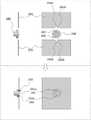
레이저모듈(100)은 레이저장치(10)의 내부에 수용되며 레이저광을 생성하여 광섬유커플러(110)를 통해 레이저광을 집중시켜 외부로 출력시키는 역할을 하며, 통상적으로는 도 1과 같이 출력모듈(300)의 커넥터(310)가 광섬유(320)를 광섬유커플러(110)에 접속시켜 레이저모듈(100)에서 출력되는 레이저광이 광섬유(320)를 통해 전송되도록 구성된다. 이 때 커넥터(310)는 주로 SMA커넥터가 사용된다.The
그러나 도 2와 같이 출력모듈(300)의 광섬유(320)에 인장력이나 외력이 작용하여 커넥터(310)에 충격이 가해지게 되면, 커넥터(310) 뿐만 아니라 레이저모듈(100)의 광섬유커플러(110)에도 충격이 가해져 얼라인먼트(alignment)에 문제가 발생하게 되고, 이로 인해 레이저출력 품질이 저하되거나 불량이 발생하기 십상이다.2, when a tensile force or an external force acts on the
특히 레이저모듈의 출력단에 불량이 발생하게 되면 이를 교정하기 위해서는 매우 정밀한 기술을 요하므로, 제조사로 보내 부품자체를 교체하거나 교정서비스를 받아야 하므로 비용과 시간이 많이 소요되는 단점이 있다.In particular, if a defect occurs in the output terminal of the laser module, it requires a very precise technology to correct the error, so it is costly and time consuming to replace the component itself or receive the calibration service.
본 발명에서 해결하고자 하는 과제는 다음과 같다.Problems to be solved by the present invention are as follows.
즉, 레이저광을 전송하는 광섬유에 작용하는 인장력이나 외력에 의해 광섬유 커넥터에 충격이 가해지더라도 그 충격이 레이저모듈의 출력단에 직접 전달되지 않게 함으로써 레이저모듈의 출력단을 보호할 수 있는 구조를 제시하고자 한다.That is, even if an impact is applied to an optical fiber connector due to a tensile force or an external force acting on an optical fiber for transmitting laser light, a structure capable of protecting the output terminal of the laser module by preventing the impact from being directly transmitted to the output terminal of the laser module .
본 발명은 위와 같은 과제를 해결하기 위하여,In order to solve the above problems,
레이저장치(10)의 내부에 수용되며 레이저광을 생성하여 광섬유커플러(110)를 통해 레이저광을 집중시켜 외부로 출력시키는 레이저모듈(100); 레이저장치(10)의 하우징에 고정되며 레이저모듈(100)과 출력모듈(300)의 사이에서 레이저광의 전송을 중계하는 중계모듈(200); 레이저장치(10)의 외부에서 중계모듈(200)에 연결되는 커넥터(310)와 레이저광을 전송하는 광섬유(320)로 구성된 출력모듈(300);을 포함하고, 상기 중계모듈(200)은 레이저광을 전송하는 광섬유(220), 광섬유(220)의 입력단을 레이저모듈의 광섬유커플러(110)에 결합시켜 광섬유커플러(110)를 통해 출력되는 레이저광을 광섬유(220)로 입력시키는 커넥터(210), 레이저장치(10)의 외부로 노출되며 광섬유(220)의 출력단과 출력모듈의 커넥터(310)를 결합시키는 중계어댑터(240), 중계어댑터(240)를 레이저장치(10)의 하우징에 고정결합시키는 고정수단(230)을 포함하는 것을 특징으로 하고,A
상기 고정수단(230)은 레이저장치(10)의 하우징에 결합되며 하단 중앙에 반원으로 함몰된 관통부(231a)에 의해 중계어댑터(240)의 상부를 지지하는 상부패널(231), 레이저장치(10)의 하우징에 결합되며 상단 중앙에 반원으로 함몰된 관통부(232a)에 의해 중계어댑터(240)의 하부를 지지하는 하부패널(232), 상부패널의 체결부(231b) 또는 하부패널의 체결부(232b)가 형성된 위치에서 상부패널 또는 하부패널의 내측면에 설치되며 체결부(231b,232b)에 체결수단이 근접하는지 센싱하는 근접센서(233), 중계어댑터(240)의 상부와 하부를 지지하면서 중계어댑터(240)를 고정시키도록 상부패널(231)을 하방으로, 하부패널(232)을 상방으로 이동시키거나, 중계어댑터(240)의 고정을 해제시키도록 상부패널(231)을 상방으로, 하부패널(232)을 하방으로 이동시키기 위한 패널조절수단(234)을 포함하고, 상기 패널조절수단(234)은 상부패널(231) 및 하부패널(232)의 양단 및 레이저장치(10)에 고정결합되어 상하부패널(231,232)의 상하이동을 가이드하는 가이드레일(234a), 상부패널(231) 및 하부패널(232)의 측단부에 형성되는 래크(234c), 상부패널(231) 및 하부패널(232)의 측단부에 설치되며 래크(234c)와 맞물려 상부패널(231) 및 하부패널(232)을 상하이동시키는 피니언(234b)을 포함하는 것을 특징으로 하거나,The fixing means 230 includes an
상기 상부패널(231)은 중계어댑터의 상부체결부(241)를 관통하는 체결수단이 관통하여 결합되는 체결부(231b), 상부패널(231)의 하단부가 관통부(231a)로 접근할 수록 위로 경사지도록 형성된 부분으로서 상부패널(231)이 하방으로 이동되는 동안 중계어댑터(240)가 관통부(231a)에 위치하도록 유인하는 어댑터유인부(231c)를 포함하고, 상기 하부패널(232)은 중계어댑터의 하부체결부(242)를 관통하는 체결수단이 관통하여 결합되는 체결부(232b), 하부패널(232)의 상단부가 관통부(232a)로 접근할 수록 아래로 경사지도록 형성된 부분으로서 하부패널(232)이 상방으로 이동되는 동안 중계어댑터(240)가 체결부(232b)에 위치하도록 유인하는 어댑터유인부(232c)를 포함하며, 상기중계어댑터(240)는 상부패널(231)과 겹쳐지는 중계어댑터(240)의 플랜지 일측에 체결수단이 관통하는 홀로 형성된 상부체결부(241), 하부패널(232)과 겹쳐지는 중계어댑터(240)의 플랜지 일측에 체결수단이 관통하는 홀로 형성된 하부체결부(242), 상부패널(231)의 외측면에 하부패널(232)의 내측면이 맞닿도록 결합되어 중계어댑터(240)를 고정할 때 하부패널(232)의 상단부 형상에 맞게 형성된 단턱으로서 단턱을 기준으로 중계어댑터(240)의 내측상부면은 상부패널(231)의 외측면과 맞닿고, 중계어댑터(240)의 내측하부면은 하부패널(232)의 하부패널(232)의 외측면과 맞닿도록 형성된 걸림턱(243)을 포함하는 것을 특징으로 하는 레이저모듈 출력단 보호를 위한 광섬유 체결용 구조물을 제시한다.The
본 발명은 다음과 같은 효과를 발휘한다.The present invention has the following effects.
즉, 레이저광을 전송하는 광섬유에 작용하는 인장력이나 외력에 의해 광섬유 커넥터에 충격이 가해지더라도 그 충격이 레이저모듈의 출력단에 직접 전달되지 않게 되어 레이저모듈의 출력단을 보호할 수 있다.That is, even if an impact is applied to the optical fiber connector due to a tensile force or an external force acting on the optical fiber that transmits the laser light, the impact is not directly transmitted to the output terminal of the laser module, and the output terminal of the laser module can be protected.
또한, 광섬유 커넥터로 충격이 가해져 부품손상이 생기더라도 레이저모듈의 출력단에 손상이 가지 않고 중계모듈에 손상이 가므로, 중계모듈만 손쉽게 교체할 수 있는 장점이 있다.In addition, even if a component is damaged due to an impact due to the optical fiber connector, the output module of the laser module is not damaged and the relay module is damaged, so that only the relay module can be easily replaced.
도 1은 레이저모듈이 수용되는 레이저장치에 대한 종래의 구조를 간략히 나타낸 도면.
도 2는 도 1의 예에서 광섬유에 장력이 작용될 때 레이저모듈의 출력단에 충격이 가해지는 과정을 나타낸 도면.
도 3은 본 발명의 구성을 간략히 나타낸 도면.
도 4는 본 발명의 실시예에서 광섬유에 장력이 작용될 때 중계모듈에 충격이 가해지는 과정을 나타낸 도면.
도 5는 상하부패널이 상하이동하면서 중계어댑터를 고정하는 과정을 나타낸 도면.
도 6은 상하부패널이 상하이동할 때 어댑터유인부에 의해 중계어댑터가 중앙으로 유인되는 과정을 나타낸 도면.
도 7은 도 6에서 (a-a)단면도와 (b-b)단면도로서 걸림턱이 형성된 중계어댑터와 상하부패널이 결합된 상태를 나타낸 도면.
도 8은 중계어댑터의 구조를 구체적으로 나타낸 도면,BRIEF DESCRIPTION OF THE DRAWINGS Figure 1 schematically illustrates a conventional structure for a laser device in which a laser module is housed.
2 is a diagram illustrating a process in which an impact is applied to an output end of a laser module when tensile force is applied to an optical fiber in the example of FIG.
Fig. 3 schematically shows a configuration of the present invention; Fig.
4 is a diagram illustrating a process in which an impact is applied to a relay module when tensile force is applied to an optical fiber in an embodiment of the present invention.
5 is a view showing a process of fixing the relay adapter with the upper and lower panels moving up and down.
6 is a view showing a process in which the relay adapter is attracted to the center by the adapter attracting part when the upper and lower panels move up and down.
7 is a cross-sectional view (aa) and a cross-sectional view (bb) in Fig. 6, showing a state in which the relay adapter having the latching jaws and the upper and lower panels are coupled.
8 is a diagram specifically showing a structure of a relay adapter,
이하 첨부된 도면을 바탕으로 본 발명의 바람직한 실시예에 대해 설명한다. 다만 본 발명의 권리범위는 특허청구범위 기재에 의하여 파악되어야 한다. 또한 본 발명의 요지를 모호하게 하는 공지기술의 설명은 생략한다.DETAILED DESCRIPTION OF THE PREFERRED EMBODIMENTS Hereinafter, preferred embodiments of the present invention will be described with reference to the accompanying drawings. However, the scope of the present invention should be understood from the description of the claims. Further, the description of known technology which obscures the gist of the present invention is omitted.
본 발명의 레이저모듈 출력단 보호를 위한 광섬유 체결용 구조물은 도 1의 레이저모듈(100) 및 출력모듈(300)과 이의 연결을 중계하는 중계모듈(200)로 구성된다.The optical fiber fastening structure for protecting the output end of the laser module of the present invention comprises a
레이저모듈(100)은 레이저장치(10)의 내부에 수용되며 레이저광을 생성하여 광섬유커플러(110)를 통해 레이저광을 집중시켜 외부로 출력시키는 역할을 하며, 통상적으로는 출력모듈(300)의 커넥터(310)가 광섬유(320)를 광섬유커플러(110)에 접속시켜 레이저모듈(100)에서 출력되는 레이저광이 광섬유(320)를 통해 전송되도록 구성된다. 광섬유커플러(110)는 광섬유콜리메이터로 대체할 수도 있다.The
그러나 본 발명에서는 레이저모듈(100)과 출력모듈(300) 사이에 중계모듈(200)이 추가되는데, 중계모듈(200)은 레이저장치(10)의 하우징(11)에 고정되며 레이저모듈(100)과 출력모듈(300)의 사이에서 레이저광의 전송을 중계하는 역할을 하며, 레이저장치(10)의 외부에서 출력모듈(300)의 커넥터(310)가 중계모듈(200)에 연결되어 레이저모듈(100)에서 생성된 레이저광이 중계모듈(200)을 거쳐 출력모듈(300)의 광섬유(320)로 전송된다.However, in the present invention, a
중계모듈(200)은 도 3 및 도 4에 도시된 바와 같이 광섬유(220), 커넥터(210), 중계어댑터(240), 고정수단(230)으로 구성된다.The
광섬유(220)는 레이저모듈의 광섬유커플러(110)에서 출력되는 레이저광을 출력모듈(300)로 전송시키는 역할을 하며, 레이저광이 들어오는 일측단은 커넥터(210)에 의해 광섬유커플러(110)에 연결되고, 레이저광이 빠져나가는 타측단은 중계어댑터(240)에 의해 출력모듈의 커넥터(310)에 연결된다.The
커넥터(210)는 광섬유(220)의 입력단을 레이저모듈의 광섬유커플러(110)에 결합시켜 광섬유커플러(110)를 통해 출력되는 레이저광을 광섬유(220)로 입력시키는 역할을 한다.The
중계어댑터(240)는 레이저장치(10)의 외부로 노출되며 광섬유(220)의 출력단과 출력모듈의 커넥터(310)를 결합시키는 역할을 한다.The
고정수단(230)은 중계어댑터(240)를 레이저장치(10)의 하우징(11)에 고정결합시키기 위한 것으로서, 도 4 내지 6에 도시된 바와 같이 상부패널(231), 하부패널(232), 근접센서(233), 패널조절수단(234)으로 구성된다.The fixing means 230 is for fixing the
상부패널(231)은 레이저장치(10)의 하우징(11)에 결합되며 하단 중앙에 반원으로 함몰된 관통부(231a)에 의해 중계어댑터(240)의 상부를 지지하는 역할을 한다. 즉, 상부패널(231)과 하부패널(232)이 맞닿으면서 상부패널(231)의 관통부(231a)와 하부패널(232)의 관통부(232a)가 중계어댑터(240)에 대응되는 관통홀을 형성하게 되고, 이 관통홀에 중계어댑터(240)가 수용되어 고정되는 것이다.The
하부패널(232)은 상부패널(231)과 대응되는 형상으로서, 레이저장치(10)의 하우징(11)에 결합되며 상단 중앙에 반원으로 함몰된 관통부(232a)에 의해 중계어댑터(240)의 하부를 지지하게 된다.The
상하부패널(231,232)은 각각 체결부(231b,232b), 어댑터유인부(231c,232c)를 더 포함하게 된다.The upper and
체결부(231b,232b)는 중계어댑터의 상하부체결부(241,242)를 관통하는 체결수단이 관통하여 결합되는 부분으로서, 도시된 바와 상부패널(231)과 하부패널(232)이 중계어댑터(240)를 고정한 상태에서 중계어댑터(240)의 상하부체결부(241,242)와 대응되는 위치에 형성된다. 중계어댑터(240)를 상하부패널(231,232)에 부착시킴과 동시에 중계어댑터(240)가 회전되지 않도록 잡아주는 역할도 한다.The
어댑터유인부(231c,232c)는 상부패널(231)의 하단부 및 하부패널(232)의 상단부가 관통부(231a,232a)로 접근할 수록 상부패널은 위로, 하부패널은 아래로 경사지도록 형성된 부분으로서, 중계어댑터(240)를 고정하기 위해 상부패널(231)이 하방으로 이동되고 하부패널(232)이 상방으로 이동되는 동안 중앙에서 빗겨난 중계어댑터(240)가 관통부(231a)에 위치하도록 유인하는 역할을 한다.The adapter attracting portions 231c and 232c are formed such that the lower panel of the
즉, 어댑터유인부(231c,232c)가 형성되지 않은 도 5에서는 중계어댑터(240)를 중앙에 위치시킨 상태에서 상하부패널(231,232)을 이동시켜야 상하부패널(231,232)의 관통부(231a,232b)에 중계어댑터(240)가 안착된다. 그러나 도 6과 같이 하부패널(232)의 상단이 어댑터유인부(232c)에 의해 관통부(232a)를 꼭지점으로한 'V'자 형태로 형성되고, 상부패널(231)의 하단 역시 어댑터유인부(231c)에 의해 관통부(231a)를 꼭지점으로 한 뒤집은 'V'자 형태로 형성되면 중계어댑터(240)가 하우징(11)의 레이저장치관통부(11a) 중앙에서 다소 빗겨나가 있더라도, 상하부패널(231,232)이 패널조절수단(234)에 의해 조여지면서 중계어댑터(240)도 어댑터유인부(231c,232c)에서 미끄러져 자연스럽게 중앙의 관통부(231a,232b)로 유인되면서 안착되는 것이다. 이 때, 레이저장치관통부(11a)는 레이저장치(10)의 내부에 있는 레이저모듈(100)로부터 출력되는 레이저광이 레이저장치(10)의 외부로 전송되기 위한 통로에 해당한다.5 in which the adapter attracting portions 231c and 232c are not formed, the upper and
근접센서(233)는 상부패널의 체결부(231b) 또는 하부패널의 체결부(232b)가 형성된 위치에서 상부패널 또는 하부패널의 내측면에 설치되며 체결부(231b,232b)에 체결수단이 근접하는지 센싱하는 역할을 한다. 만약 체결수단이 근접한 상태로 감지되면 중계어댑터(240)와 상부패널(231) 및 하부패널(232)이 고정되어 있는 상태로서, 패널조절수단(234)에 의해 상부패널(231)과 하부패널(232)을 상하로 이동시키고자 하면 부품 손상을 야기할 수 있으므로 이를 차단하기 위함이다.The
도 4와 같이 출력모듈(300)의 광섬유(320)에 장력이 작용되어 출력모듈(300)의 커넥터(310) 및 중계모듈(200)의 중계어댑터(240)에 충격이 가해질 경우, 레이저모듈(100)의 광섬유커플러(110)에 힘이 전달되지 않더라도 중계어댑터(240)는 충격에 의한 파손으로 교체해주어야 할 상황이 발생할 수 있다. 이 때 패널조절수단(234)에 의해 상부패널(231)을 상부로, 하부패널(232)을 하부로 이동시켜 중계어댑터(240)가 상하부패널(231,232)에 의해 구속된 상태를 해제함으로써 중계어댑터(240)만 손쉽게 교체할 수 있다.4, when a tension is applied to the
그런데 이 때 근접센서(233)가 설치되지 않은 경우, 상부패널(231)의 체결부(231b)에 체결수단이 체결되어 있지 않고, 하부패널(232)의 체결부(232b)에만 체결수단이 체결되어 중계어댑터(240)가 하부패널(232)에 고정되어 있을 수 있는데(사용자 부주의에 의해 발생 가능함), 이 때 패널조절수단(234)에 의해 상부패널(231)을 상부로, 하부패널(232)을 하부로 이동시키면 중계어댑터(240)가 하부패널(232)에 고정되어 같이 이동하므로 중계모듈(200)의 광섬유(220)에 장력이 걸리고 결국 레이저모듈(100)의 광섬유커플러(110)에 아래 방향으로 힘이 가해지게 된다. 이로써 광섬유(220) 또는 광섬유커플러(110)의 정렬 불량을 초래하고 부품을 손상시키게 된다.In this case, when the
양 체결부(231b,232b)에 모두 체결수단이 체결된 상태에서 패널조절수단(234)에 의해 상부패널(231)을 상부로, 하부패널(232)을 하부로 이동시킬 경우 상부패널(231), 하부패널(232) 및 중계어댑터(240)에 손상이 야기됨은 물론이다.The
따라서 두 체결부(231b,232b)에 모두 근접센서(233)를 설치함이 바람직하다.Therefore, it is preferable to provide the
패널조절수단(234)은 중계어댑터(240)의 상부와 하부를 지지하면서 중계어댑터(240)를 고정시키도록 상부패널(231)을 하방으로, 하부패널(232)을 상방으로 이동시키거나, 중계어댑터(240)의 고정을 해제시키도록 상부패널(231)을 상방으로, 하부패널(232)을 하방으로 이동시키는 역할을 하며, 가이드레일(234a), 피니언(234b), 래크(234c)로 구성된다.The panel adjusting means 234 moves the
가이드레일(234a)은 상부패널(231) 및 하부패널(232)의 양단 및 레이저장치(10)에 고정결합되어 상하부패널(231,232)의 상하이동을 가이드하는 레일로 구성된다. 도 5와 같이 상부패널(231)과 하부패널(232)이 단차 없이 평면상에서 결합되는 경우 상부패널(231)에서 하부패널(232)로 이어지는 단일 레일로 상하부패널(231,232)의 양단에 2개 구비될 수 있으나, 도 6과 같이 상부패널(231)과 하부패널(232)이 어댑터유인부(231c,232c)에 의해 단차를 형성할 경우(레이저장치(10)의 하우징(11), 상부패널(231), 하부패널(232) 순으로 적층됨) 레이저장치(10)의 하우징(11)을 기준으로 상부패널(231)보다 하부패널(232)의 이동위치가 하우징(11)에서 더 떨어지게 되므로 가이드레일(234a)은 각각 별도로 구비함이 바람직하다. 즉, 상부패널(231)의 양측 2개와 하부패널(232)의 양측 2개로 4개의 가이드레일(234a)이 구비되는 것이다.The
래크(234c)는 상부패널(231) 및 하부패널(232)의 측단부에 형성되는 것으로서 피니언(234b)과 맞물려 상부패널(231) 및 하부패널(232)을 상하이동시키는 역할을 한다. 래크(234c)는 상부패널(231) 및 하부패널(232)의 왼쪽 또는 오른쪽에만 형성될 수도 있고, 좌우 양쪽 단부 모두 래크(234c)로 형성될 수도 있을 것이다.The
피니언(234b)은 상부패널(231) 및 하부패널(232)의 측단부에 설치되며 래크(234c)와 맞물려 상부패널(231) 및 하부패널(232)을 상하이동시키는 역할을 한다. 래크(234c)와 대응되도록 상부패널(231) 및 하부패널(232)의 왼쪽 또는 오른쪽에만 형성되거나 좌우 양쪽 단부에 형성될 수도 있다.The pinion 234b is installed at the side end portions of the
도 8은 중계어댑터(240)를 상세히 도시한 것으로서, 중계어댑터(240)는 상부체결부(241), 하부체결부(242), 걸림턱(243)으로 구성된다.8 shows the
상부체결부(241)는 상부패널(231)과 겹쳐지는 중계어댑터(240)의 플랜지 일측에 체결수단이 관통하는 홀로 형성된 것이고, 하부체결부(242)는 하부패널(232)과 겹쳐지는 중계어댑터(240)의 플랜지 일측에 체결수단이 관통하는 홀로 형성된 것이다.The
걸림턱(243)은 도 7 및 도 8을 참고하면 상부패널(231)의 외측면에 하부패널(232)의 내측면이 맞닿도록 결합되어 중계어댑터(240)를 고정할 때(단차를 형성하면서 결합될 때) 하부패널(232)의 상단부 형상에 맞게 형성된 단턱이다. 걸림턱(243)을 기준으로 중계어댑터(240)의 내측상부면(A1)은 상부패널(231)의 외측면(A2)과 맞닿고, 중계어댑터(240)의 내측하부면(B1)은 하부패널(232)의 하부패널(232)의 외측면(B2)과 맞닿도록 형성된다. 이는 중계어댑터(240)가 고정수단(230)의 어댑터유인부(231c,232c)에 의해 관통부(231a,232a)로 유인될 때 하부패널(232)에 걸쳐진 상태에서 안정적으로 이동하다 하부패널(232)의 관통부(232a)에 안착되도록 하기 위한 구성이다.7 and 8, when the inner surface of the
이상에서 설명한 본 발명은 전술한 실시예 및 첨부된 도면에 의해 한정되는 것은 아니고, 본 발명의 기술적 사상을 벗어나지 않는 범위 내에서 여러 가지 치환, 변형 및 변경 가능함은 본 발명이 속하는 기술분야에서 통상의 지식을 가진 자에게 있어서 명백할 것이다.While the present invention has been described in connection with what is presently considered to be practical exemplary embodiments, it is to be understood that the invention is not limited to the disclosed embodiments, but, on the contrary, It will be clear to those who have knowledge.
10 : 레이저장치
11 : 하우징
11a : 레이저장치관통부
100 : 레이저모듈
110 : 광섬유커플러
200 : 중계모듈
210 : 커넥터
220 : 광섬유
230 : 고정수단
231 : 상부패널
231a : 관통부
231b : 체결부
231c : 어댑터유인부
232 : 하부패널
232a : 관통부
232b : 체결부
232c : 어댑터유인부
233 : 근접센서
234 : 패널조절수단
234a : 가이드레일
234b : 피니언
234c : 래크
240 : 중계어댑터
241 : 상부체결부
242 : 하부체결부
243 : 걸림턱
300 : 출력모듈
310 : 커넥터
320 : 광섬유10: Laser device
11: Housing
11a: laser device penetration part
100: Laser module
110: Fiber Optic Coupler
200: Relay module
210: Connector
220: Optical fiber
230: Fixing means
231: upper panel
231a:
231b:
231c: Adapter attracting part
232: Lower panel
232a:
232b:
232c: Adapter attractor
233: Proximity sensor
234: Panel adjustment means
234a: guide rail
234b: Pinion
234c: Rack
240: Relay adapter
241:
242: Lower fastening portion
243:
300: Output module
310: connector
320: Optical fiber
Claims (3)
Translated fromKorean레이저장치(10)의 하우징에 고정되며 레이저모듈(100)과 출력모듈(300)의 사이에서 레이저광의 전송을 중계하는 중계모듈(200);
레이저장치(10)의 외부에서 중계모듈(200)에 연결되는 커넥터(310)와 레이저광을 전송하는 광섬유(320)로 구성된 출력모듈(300);을 포함하고,
상기 중계모듈(200)은
레이저광을 전송하는 광섬유(220),
광섬유(220)의 입력단을 레이저모듈의 광섬유커플러(110)에 결합시켜 광섬유커플러(110)를 통해 출력되는 레이저광을 광섬유(220)로 입력시키는 커넥터(210),
레이저장치(10)의 외부로 노출되며 광섬유(220)의 출력단과 출력모듈의 커넥터(310)를 결합시키는 중계어댑터(240),
중계어댑터(240)를 레이저장치(10)의 하우징에 고정결합시키는 고정수단(230)을 포함하고,
상기 고정수단(230)은
레이저장치(10)의 하우징에 결합되며 하단 중앙에 반원으로 함몰된 관통부(231a)에 의해 중계어댑터(240)의 상부를 지지하는 상부패널(231),
레이저장치(10)의 하우징에 결합되며 상단 중앙에 반원으로 함몰된 관통부(232a)에 의해 중계어댑터(240)의 하부를 지지하는 하부패널(232),
상부패널의 체결부(231b) 또는 하부패널의 체결부(232b)가 형성된 위치에서 상부패널 또는 하부패널의 내측면에 설치되며 체결부(231b,232b)에 체결수단이 근접하는지 센싱하는 근접센서(233),
중계어댑터(240)의 상부와 하부를 지지하면서 중계어댑터(240)를 고정시키도록 상부패널(231)을 하방으로, 하부패널(232)을 상방으로 이동시키거나, 중계어댑터(240)의 고정을 해제시키도록 상부패널(231)을 상방으로, 하부패널(232)을 하방으로 이동시키기 위한 패널조절수단(234)을 포함하고,
상기 패널조절수단(234)은
상부패널(231) 및 하부패널(232)의 양단 및 레이저장치(10)에 고정결합되어 상하부패널(231,232)의 상하이동을 가이드하는 가이드레일(234a),
상부패널(231) 및 하부패널(232)의 측단부에 형성되는 래크(234c),
상부패널(231) 및 하부패널(232)의 측단부에 설치되며 래크(234c)와 맞물려 상부패널(231) 및 하부패널(232)을 상하이동시키는 피니언(234b)을 포함하는 것을 특징으로 하는
레이저모듈 출력단 보호를 위한 광섬유 체결용 구조물.
A laser module 100 accommodated in the laser device 10 and generating laser light to concentrate the laser light through the optical fiber coupler 110 and output the laser light to the outside;
A relay module (200) fixed to the housing of the laser device (10) and relaying the transmission of laser light between the laser module (100) and the output module (300);
And an output module 300 composed of a connector 310 connected to the relay module 200 from the outside of the laser device 10 and an optical fiber 320 transmitting laser light,
The relay module (200)
An optical fiber 220 for transmitting laser light,
A connector 210 coupling the input end of the optical fiber 220 to the optical fiber coupler 110 of the laser module and inputting the laser light output through the optical fiber coupler 110 to the optical fiber 220,
A relay adapter 240 exposed to the outside of the laser device 10 and coupling the output terminal of the optical fiber 220 and the connector 310 of the output module,
And fixing means (230) for fixing the relay adapter (240) to the housing of the laser device (10)
The fixing means (230)
An upper panel 231 coupled to the housing of the laser apparatus 10 and supporting an upper portion of the relay adapter 240 by a penetration portion 231a recessed in a semicircular shape at the center of the lower end,
A lower panel 232 coupled to the housing of the laser device 10 and supporting a lower portion of the relay adapter 240 by a penetration part 232a recessed in a semicircle at an upper center,
A proximity sensor installed on the inner surface of the upper panel or the lower panel at a position where the fastening portion 231b of the upper panel or the fastening portion 232b of the lower panel is formed and sensing whether the fastening means is close to the fastening portions 231b and 232b 233),
The upper panel 231 is moved downward and the lower panel 232 is moved upward to fix the relay adapter 240 while the upper and lower portions of the relay adapter 240 are supported, And a panel adjusting means (234) for moving the upper panel (231) upward to lower the lower panel (232)
The panel adjustment means (234)
A guide rail 234a fixedly coupled to both ends of the upper panel 231 and the lower panel 232 and the laser device 10 to guide upward and downward movement of the upper and lower panels 231 and 232,
A rack 234c formed at a side end portion of the upper panel 231 and the lower panel 232,
And a pinion 234b provided at the side end portions of the upper panel 231 and the lower panel 232 and engaging with the rack 234c to move the upper panel 231 and the lower panel 232 up and down.
Fiber optic fastening structure for laser module output stage protection.
상기 상부패널(231)은
중계어댑터의 상부체결부(241)를 관통하는 체결수단이 관통하여 결합되는 체결부(231b),
상부패널(231)의 하단부가 관통부(231a)로 접근할 수록 위로 경사지도록 형성된 부분으로서 상부패널(231)이 하방으로 이동되는 동안 중계어댑터(240)가 관통부(231a)에 위치하도록 유인하는 어댑터유인부(231c)를 포함하고,
상기 하부패널(232)은
중계어댑터의 하부체결부(242)를 관통하는 체결수단이 관통하여 결합되는 체결부(232b),
하부패널(232)의 상단부가 관통부(232a)로 접근할 수록 아래로 경사지도록 형성된 부분으로서 하부패널(232)이 상방으로 이동되는 동안 중계어댑터(240)가 체결부(232b)에 위치하도록 유인하는 어댑터유인부(232c)를 포함하며,
상기중계어댑터(240)는
상부패널(231)과 겹쳐지는 중계어댑터(240)의 플랜지 일측에 체결수단이 관통하는 홀로 형성된 상부체결부(241),
하부패널(232)과 겹쳐지는 중계어댑터(240)의 플랜지 일측에 체결수단이 관통하는 홀로 형성된 하부체결부(242),
상부패널(231)의 외측면에 하부패널(232)의 내측면이 맞닿도록 결합되어 중계어댑터(240)를 고정할 때 하부패널(232)의 상단부 형상에 맞게 형성된 단턱으로서 단턱을 기준으로 중계어댑터(240)의 내측상부면은 상부패널(231)의 외측면과 맞닿고, 중계어댑터(240)의 내측하부면은 하부패널(232)의 하부패널(232)의 외측면과 맞닿도록 형성된 걸림턱(243)을 포함하는 것을 특징으로 하는
레이저모듈 출력단 보호를 위한 광섬유 체결용 구조물.
The method according to claim 1,
The upper panel 231
A fastening portion 231b through which fastening means penetrating through the upper fastening portion 241 of the relay adapter is coupled through,
The relay adapter 240 is attracted to the penetrating portion 231a while the upper panel 231 is moved downward as a portion formed such that the lower end portion of the upper panel 231 approaches the penetrating portion 231a and tilts upward An adapter attracting section 231c,
The lower panel 232
A fastening part 232b through which fastening means penetrating through the lower fastening part 242 of the relay adapter is inserted,
The relay adapter 240 is positioned so as to be positioned at the fastening portion 232b while the lower panel 232 is moved upward as a portion formed such that the upper end portion of the lower panel 232 is inclined downward as it approaches the penetrating portion 232a An adapter attraction portion 232c,
The relay adapter 240
An upper coupling part 241 formed at one side of the flange of the relay adapter 240 overlapping the upper panel 231,
A lower coupling part 242 formed at one side of the flange of the relay adapter 240 that overlaps with the lower panel 232,
The inner surface of the lower panel 232 is in contact with the outer surface of the upper panel 231 so as to be in contact with the outer surface of the lower panel 232 to fix the relay adapter 240, The inner lower surface of the relay adapter 240 abuts against the outer surface of the upper panel 231 and the inner lower surface of the relay adapter 240 abuts against the outer surface of the lower panel 232 of the lower panel 232, (243) < / RTI >
Fiber optic fastening structure for laser module output stage protection.
Priority Applications (1)
| Application Number | Priority Date | Filing Date | Title |
|---|---|---|---|
| KR1020180136729AKR101957768B1 (en) | 2018-11-08 | 2018-11-08 | Optical fiber connecting apparatus for protecting output terminal of laser module |
Applications Claiming Priority (1)
| Application Number | Priority Date | Filing Date | Title |
|---|---|---|---|
| KR1020180136729AKR101957768B1 (en) | 2018-11-08 | 2018-11-08 | Optical fiber connecting apparatus for protecting output terminal of laser module |
Publications (1)
| Publication Number | Publication Date |
|---|---|
| KR101957768B1true KR101957768B1 (en) | 2019-03-14 |
Family
ID=65759423
Family Applications (1)
| Application Number | Title | Priority Date | Filing Date |
|---|---|---|---|
| KR1020180136729AActiveKR101957768B1 (en) | 2018-11-08 | 2018-11-08 | Optical fiber connecting apparatus for protecting output terminal of laser module |
Country Status (1)
| Country | Link |
|---|---|
| KR (1) | KR101957768B1 (en) |
Citations (2)
| Publication number | Priority date | Publication date | Assignee | Title |
|---|---|---|---|---|
| JP2013513454A (en)* | 2009-12-15 | 2013-04-22 | アルコン リサーチ, リミテッド | Multi-spot laser probe |
| KR101723115B1 (en) | 2015-09-30 | 2017-04-05 | 한국생산기술연구원 | Optical fiber connector having holding element |
- 2018
- 2018-11-08KRKR1020180136729Apatent/KR101957768B1/enactiveActive
Patent Citations (2)
| Publication number | Priority date | Publication date | Assignee | Title |
|---|---|---|---|---|
| JP2013513454A (en)* | 2009-12-15 | 2013-04-22 | アルコン リサーチ, リミテッド | Multi-spot laser probe |
| KR101723115B1 (en) | 2015-09-30 | 2017-04-05 | 한국생산기술연구원 | Optical fiber connector having holding element |
Similar Documents
| Publication | Publication Date | Title |
|---|---|---|
| JP6832038B6 (en) | Optical communication assembly | |
| US11803020B2 (en) | Optical bench subassembly having integrated photonic device | |
| US20210278606A1 (en) | Optical ferrule and connector | |
| JP6994258B2 (en) | Optical alignment of optical subassemblies for optoelectronic devices | |
| US5619609A (en) | Fiberoptic support clip | |
| US6734517B2 (en) | Semiconductor laser diode module | |
| US9897769B2 (en) | Vision-based passive alignment of an optical fiber subassembly to an optoelectronic device | |
| WO2013049494A3 (en) | Optical component assemblies | |
| US20090304337A1 (en) | Optical sub-assembly electrically isolating frame ground from signal ground | |
| US9784929B2 (en) | Board connector | |
| US10686292B2 (en) | Laser module | |
| US6669379B2 (en) | Method of attaching optical fiber in alignment with a light source in an optical module | |
| KR101957768B1 (en) | Optical fiber connecting apparatus for protecting output terminal of laser module | |
| US20170003463A1 (en) | Passive placement of a laser on a photonic chip | |
| US6606435B1 (en) | Laser diode module and its manufacture method | |
| US20120288231A1 (en) | Laser package including tilted laser and method of using same | |
| JP6898245B2 (en) | Optical bench subassembly with integrated optical device | |
| KR101480833B1 (en) | Optical connector and method for manufacturing the connector | |
| US6659657B2 (en) | Easily assembled transceiver module with high yield rate | |
| KR100591264B1 (en) | Optical connector module | |
| US20050175292A1 (en) | Method for coupling a surface-oriented optoelectronic component to an optical fiber | |
| US20040202478A1 (en) | Electro-optical module for transmitting and/or receiving optical signals of at least two optical data channels | |
| WO2024065993A1 (en) | Bosa device assembling apparatus and mounting method therefor | |
| JPH11326700A (en) | Connection casing of optical system and method for connecting optical lines | |
| JP2007328195A (en) | Optical communication module and method for manufacturing optical communication module |
Legal Events
| Date | Code | Title | Description |
|---|---|---|---|
| PA0109 | Patent application | Patent event code:PA01091R01D Comment text:Patent Application Patent event date:20181108 | |
| PA0201 | Request for examination | ||
| PA0302 | Request for accelerated examination | Patent event date:20181108 Patent event code:PA03022R01D Comment text:Request for Accelerated Examination | |
| PE0902 | Notice of grounds for rejection | Comment text:Notification of reason for refusal Patent event date:20190108 Patent event code:PE09021S01D | |
| E701 | Decision to grant or registration of patent right | ||
| PE0701 | Decision of registration | Patent event code:PE07011S01D Comment text:Decision to Grant Registration Patent event date:20190215 | |
| GRNT | Written decision to grant | ||
| PR0701 | Registration of establishment | Comment text:Registration of Establishment Patent event date:20190307 Patent event code:PR07011E01D | |
| PR1002 | Payment of registration fee | Payment date:20190307 End annual number:3 Start annual number:1 | |
| PG1601 | Publication of registration | ||
| PR1001 | Payment of annual fee | Payment date:20220221 Start annual number:4 End annual number:4 | |
| PR1001 | Payment of annual fee | Payment date:20230221 Start annual number:5 End annual number:5 | |
| PR1001 | Payment of annual fee | Payment date:20231121 Start annual number:6 End annual number:6 | |
| PR1001 | Payment of annual fee | Payment date:20250225 Start annual number:7 End annual number:7 |