KR101957563B1 - Device for manufacturing nano graphene oxide, nanocomposite comprising the same and manufacturing device thereof - Google Patents
Device for manufacturing nano graphene oxide, nanocomposite comprising the same and manufacturing device thereofDownload PDFInfo
- Publication number
- KR101957563B1 KR101957563B1KR1020170045087AKR20170045087AKR101957563B1KR 101957563 B1KR101957563 B1KR 101957563B1KR 1020170045087 AKR1020170045087 AKR 1020170045087AKR 20170045087 AKR20170045087 AKR 20170045087AKR 101957563 B1KR101957563 B1KR 101957563B1
- Authority
- KR
- South Korea
- Prior art keywords
- nanocomposite
- ngo
- dox
- nano
- prepared
- Prior art date
- Legal status (The legal status is an assumption and is not a legal conclusion. Google has not performed a legal analysis and makes no representation as to the accuracy of the status listed.)
- Expired - Fee Related
Links
Images


Classifications
- C—CHEMISTRY; METALLURGY
- C01—INORGANIC CHEMISTRY
- C01B—NON-METALLIC ELEMENTS; COMPOUNDS THEREOF; METALLOIDS OR COMPOUNDS THEREOF NOT COVERED BY SUBCLASS C01C
- C01B32/00—Carbon; Compounds thereof
- C01B32/20—Graphite
- C01B32/21—After-treatment
- C01B32/23—Oxidation
- A—HUMAN NECESSITIES
- A61—MEDICAL OR VETERINARY SCIENCE; HYGIENE
- A61K—PREPARATIONS FOR MEDICAL, DENTAL OR TOILETRY PURPOSES
- A61K31/00—Medicinal preparations containing organic active ingredients
- A61K31/33—Heterocyclic compounds
- A61K31/335—Heterocyclic compounds having oxygen as the only ring hetero atom, e.g. fungichromin
- A61K31/337—Heterocyclic compounds having oxygen as the only ring hetero atom, e.g. fungichromin having four-membered rings, e.g. taxol
- A—HUMAN NECESSITIES
- A61—MEDICAL OR VETERINARY SCIENCE; HYGIENE
- A61K—PREPARATIONS FOR MEDICAL, DENTAL OR TOILETRY PURPOSES
- A61K31/00—Medicinal preparations containing organic active ingredients
- A61K31/70—Carbohydrates; Sugars; Derivatives thereof
- A61K31/7028—Compounds having saccharide radicals attached to non-saccharide compounds by glycosidic linkages
- A61K31/7034—Compounds having saccharide radicals attached to non-saccharide compounds by glycosidic linkages attached to a carbocyclic compound, e.g. phloridzin
- A61K31/704—Compounds having saccharide radicals attached to non-saccharide compounds by glycosidic linkages attached to a carbocyclic compound, e.g. phloridzin attached to a condensed carbocyclic ring system, e.g. sennosides, thiocolchicosides, escin, daunorubicin
- B—PERFORMING OPERATIONS; TRANSPORTING
- B01—PHYSICAL OR CHEMICAL PROCESSES OR APPARATUS IN GENERAL
- B01J—CHEMICAL OR PHYSICAL PROCESSES, e.g. CATALYSIS OR COLLOID CHEMISTRY; THEIR RELEVANT APPARATUS
- B01J19/00—Chemical, physical or physico-chemical processes in general; Their relevant apparatus
- B01J19/08—Processes employing the direct application of electric or wave energy, or particle radiation; Apparatus therefor
- B01J19/087—Processes employing the direct application of electric or wave energy, or particle radiation; Apparatus therefor employing electric or magnetic energy
- B01J19/088—Processes employing the direct application of electric or wave energy, or particle radiation; Apparatus therefor employing electric or magnetic energy giving rise to electric discharges
- C—CHEMISTRY; METALLURGY
- C01—INORGANIC CHEMISTRY
- C01P—INDEXING SCHEME RELATING TO STRUCTURAL AND PHYSICAL ASPECTS OF SOLID INORGANIC COMPOUNDS
- C01P2002/00—Crystal-structural characteristics
- C01P2002/80—Crystal-structural characteristics defined by measured data other than those specified in group C01P2002/70
- C01P2002/84—Crystal-structural characteristics defined by measured data other than those specified in group C01P2002/70 by UV- or VIS- data
- C—CHEMISTRY; METALLURGY
- C01—INORGANIC CHEMISTRY
- C01P—INDEXING SCHEME RELATING TO STRUCTURAL AND PHYSICAL ASPECTS OF SOLID INORGANIC COMPOUNDS
- C01P2004/00—Particle morphology
- C01P2004/60—Particles characterised by their size
- C01P2004/64—Nanometer sized, i.e. from 1-100 nanometer
- C—CHEMISTRY; METALLURGY
- C01—INORGANIC CHEMISTRY
- C01P—INDEXING SCHEME RELATING TO STRUCTURAL AND PHYSICAL ASPECTS OF SOLID INORGANIC COMPOUNDS
- C01P2006/00—Physical properties of inorganic compounds
- C01P2006/12—Surface area
- C—CHEMISTRY; METALLURGY
- C01—INORGANIC CHEMISTRY
- C01P—INDEXING SCHEME RELATING TO STRUCTURAL AND PHYSICAL ASPECTS OF SOLID INORGANIC COMPOUNDS
- C01P2006/00—Physical properties of inorganic compounds
- C01P2006/14—Pore volume
- C—CHEMISTRY; METALLURGY
- C01—INORGANIC CHEMISTRY
- C01P—INDEXING SCHEME RELATING TO STRUCTURAL AND PHYSICAL ASPECTS OF SOLID INORGANIC COMPOUNDS
- C01P2006/00—Physical properties of inorganic compounds
- C01P2006/16—Pore diameter
Landscapes
- Health & Medical Sciences (AREA)
- Chemical & Material Sciences (AREA)
- Life Sciences & Earth Sciences (AREA)
- Organic Chemistry (AREA)
- General Health & Medical Sciences (AREA)
- Public Health (AREA)
- Medicinal Chemistry (AREA)
- Pharmacology & Pharmacy (AREA)
- Epidemiology (AREA)
- Animal Behavior & Ethology (AREA)
- Veterinary Medicine (AREA)
- Inorganic Chemistry (AREA)
- Geology (AREA)
- General Life Sciences & Earth Sciences (AREA)
- Toxicology (AREA)
- Chemical Kinetics & Catalysis (AREA)
- Molecular Biology (AREA)
- Pharmaceuticals Containing Other Organic And Inorganic Compounds (AREA)
Abstract
Translated fromKoreanDescription
Translated fromKorean본 출원은 나노 그래핀 산화물의 제조장치, 나노 복합체 및 상기 나노 복합체의 제조장치에 관한 것이다.The present invention relates to an apparatus for producing nano-graphene oxide, a nanocomposite and an apparatus for producing the nanocomposite.
최근에, 나노 의학 분야의 고수익 틈새 시장에 적합한 생기능성 나노 플랫폼 제조 분야에서, 구현 가능한 물질 디자인과 주문형(On-demand) 제조 공정이 시급히 요구되고 있다. 이러한 요구 사항을 달성하기 위한 대부분의 연구는 다양한 나노 의학용 다중 생기능성/자극-반응성 나노 플랫폼으로서, 연질(약물 및 유기 기능성 코팅) 및 경질(탄소 성 또는 금속 나노 구조) 성분을 결합한 습식 화학 방법을 사용하여 수행되었다.Recently, there is an urgent need for material design and on-demand manufacturing processes that can be implemented in the field of bio-functional nano platform manufacturing suitable for the high profit niches of nanomedical field. Much of the research to achieve these requirements is a multi-biofunctional / stimulus-responsive nano platform for a variety of nanomedical applications, including wet chemical methods combining soft (drug and organic functional coatings) and rigid (elastomeric or metal nanostructured) ≪ / RTI >
그러나, 나노 플랫폼을 제조하기 위해서는, 일반적으로 특정 화합물의 제조에만도 여러 단계의 화학 반응, 반응 제어 및 분리 공정이 필요하다. 이러한 요구 사항으로 인해 높은 비용, 원치 않는 폐기물 및 부산물이 발생할 수 있다. 따라서, 나노 플랫폼의 주문형(On-demand) 제조를 위한 간단하고, 연속적이며, 효율적인 방법이 요구된다.However, in order to manufacture a nano platform, various stages of chemical reaction, reaction control and separation processes are generally required only for the production of a specific compound. These requirements can result in high costs, unwanted wastes, and by-products. Therefore, there is a need for a simple, continuous, and efficient method for on-demand fabrication of the nano platform.
본 출원은, 공정이 단순하고, 보관 안정성이 우수하며, 그래핀 산화물의 길이 방향 및 두께 방향 모두 나노 크기로 제어할 수 있는 나노 그래핀 산화물의 제조장치, 상기 나노 그래핀 산화물의 제조장치를 통해 제조된 나노 그래핀 산화물의 큰 비표면적으로 인해 우수한 약물 적재 용량과 광열 치료 효과를 나타내는 나노 복합체 및 이의 제조장치를 제공한다.The present application relates to an apparatus for producing nano-graphene oxide which is simple in process, excellent in storage stability, and capable of controlling nano-size both in the longitudinal direction and in the thickness direction of graphene oxide, A nanocomposite exhibiting excellent drug loading capacity and photothermal therapeutic effect due to the large specific surface area of the nano-graphene oxide produced, and an apparatus for manufacturing the same.
본 출원은 나노 그래핀 산화물의 제조장치에 관한 것이다. 예시적인 본 출원의 나노 그래핀 산화물의 제조장치에 의하면, 공정이 단순하고, 보관 안정성이 우수하며, 그래핀 산화물의 길이 방향 및 두께 방향 모두 나노 크기로 제어할 수 있다.The present application relates to an apparatus for producing nano-graphene oxide. According to the exemplary apparatus for producing a nano-graphene oxide of the present application, the process is simple, the storage stability is excellent, and the graphene oxide can be controlled to have a nano-size both in the longitudinal direction and in the thickness direction.
본 출원에서 용어 「나노」는 나노 미터(nm) 단위의 크기를 의미할 수 있다. 예를 들어, 상기 나노는 1 nm 내지 1,000 nm의 크기를 의미할 수 있으나, 이에 제한되는 것은 아니다. 또한, 본 출원에서 용어 「나노 그래핀 전구체」는 길이 방향 및 두께 방향 모두 나노 미터(nm) 단위의 크기를 가지는 그래핀 전구체를 의미할 수 있다. 상기 나노 그래핀 전구체는 예를 들어, 길이 방향 및 두께 방향 모두 1 nm 내지 1,000 nm의 크기를 가지는 그래핀 전구체를 의미할 수 있으나, 이에 제한되는 것은 아니다. 또한, 본 출원에서 용어 「나노 그래핀 산화물」은 길이 방향 및 두께 방향 모두 나노 미터(nm) 단위의 크기를 가지는 그래핀 산화물을 의미할 수 있고, 예를 들어, 길이 방향 및 두께 방향 모두 1 nm 내지 1,000 nm의 크기를 가지는 그래핀 산화물을 의미할 수 있으나, 이에 제한되는 것은 아니다.The term " nano " in this application may refer to a size in nanometers (nm). For example, the nano may mean a size of 1 nm to 1,000 nm, but is not limited thereto. In addition, the term " nano-graphene precursor " in the present application may refer to a graphene precursor having a size in nanometers (nm) in both the longitudinal direction and the thickness direction. The nano-graphene precursor may, for example, mean a graphene precursor having a size in the range of 1 nm to 1,000 nm both in the longitudinal direction and in the thickness direction, but is not limited thereto. The term " nano-graphene oxide " as used in the present application may mean graphene oxide having a size in nanometers (nm) in both the longitudinal direction and the thickness direction. For example, But is not limited to, graphene oxide having a size of from about 1 nm to about 1,000 nm.
이하, 첨부된 도면을 참조로 본 출원의 나노 그래핀 산화물의 제조장치, 나노 복합체 및 상기 나노 복합체의 제조장치를 설명하나, 첨부된 도면은 예시적인 것이므로, 본 출원의 범위가 첨부된 도면에 한정되는 것은 아니다.Hereinafter, an apparatus for producing a nano-graphene oxide, a nanocomposite and an apparatus for producing the nanocomposite according to the present application will be described with reference to the accompanying drawings, but the appended drawings are exemplary only, It is not.
도 1은 본 출원의 일 구현예에 따른 나노 그래핀 산화물의 제조장치를 예시적으로 나타낸 도면이다. 도 1에 나타낸 바와 같이, 상기 나노 그래핀 산화물의 제조장치는 방전부(1110) 및 제 1 반응조(1120)를 포함한다.1 is a diagram illustrating an apparatus for producing a nano-graphene oxide according to an embodiment of the present application. As shown in FIG. 1, the apparatus for producing nano-graphene oxide includes a
상기 방전부(1110)는 방전에 의해 그래핀 전구체를 발생시키는 부분으로서, 상기 방전부(1110)는 서로 소정 간격을 두고 이격 배치된 제 1 전극(1111) 및 제 2 전극(1112)을 포함하며, 상기 제 1 전극(1111) 및 제 2 전극(1112)은 서로 이격 배치되어 간극을 형성하고 있다. 본 명세서에서 용어 「간극」은 움직이거나 고정된 두 부품 사이의 틈을 의미하며, 예를 들어, 상기 간극은 서로 이격 배치 되어 있는 제 1 전극(1111) 및 제 2 전극(1112) 사이의 틈을 의미한다.The
상기 방전은 스파크 방전 또는 아크 방전을 이용할 수 있으나, 이에 제한되는 것은 아니다. 하나의 예시에서, 상기 방전으로는 스파크 방전을 이용할 수 있다. 상기 「스파크 방전」은 상압에서 kV-mA 모드로 수행되는 고주파 방전 방식을 의미하고, 「아크 방전」은 진공에서 V-A 모드로 수행되는 고전류 방전 방식을 의미한다.The discharge may utilize a spark discharge or an arc discharge, but is not limited thereto. In one example, a spark discharge can be used as the discharge. The term " spark discharge " means a high-frequency discharge method performed in the kV-mA mode at normal pressure, and " arc discharge " means a high-current discharge method performed in vacuum mode V-A.
상기 제 1 전극(1111) 및 제 2 전극(1112)을 구성하는 재료로는 방전에 의해 그래핀 전구체를 발생시킬 수 있는 재료를 사용할 수 있다. 예를 들어, 상기 제 1 전극(1111)은 탄소를 포함하고, 상기 제 2 전극(1112)은 금속을 포함한다. 구체 예에서, 제 2 전극(1112)은 금속만을 포함하거나, 금속과 탄소를 포함할 수 있다. 이때, 상기 제 2 전극(1112)은 제 1 전극(1111)과 달리 금속을 포함함으로써, 촉매 흑연화(Catalytic Graphitization)가 촉진되어, 나노 그래핀을 보다 효율적으로 생성할 수 있다. 도 2에 나타낸 바와 같이, 방전에 의해 기화된 탄소 분자가 그래핀의 형태로 금속 입자 표면 상에 적층된다. 이때, 금속은 탄소 분자가 그래핀으로 변하는 과정에서 촉매 역할을 수행할 수 있다.As a material constituting the
상기 금속의 종류는 알칼리 금속 원소, 알칼리 토 금속 원소, 란탄족 원소, 전이 금속 원소 또는 전이후 금속 원소일 수 있다. 구체적으로, 상기 알칼리금속원소로는, 리튬(Li), 나트륨(Na), 칼륨(K) 및 루비듐(Rb) 등이 예시될 수 있고, 상기 알칼리 토 금속 원소로는 베릴륨(Be), 마그네슘(Mg), 칼슘(Ca) 및 스트론튬(Sr) 등이 예시될 수 있으며, 상기 란탄족 원소로는 란타넘(La), 세륨(Ce), 프라세오디뮴(Pr), 네오디뮴(Nd), 프로메튬(Pm), 사마륨(Sm) 및 유로퓸(Eu) 등이 예시될 수 있고, 상기 전이 금속 원소로는 철(Fe), 망간(Mn), 크롬(Cr), 니켈(Ni) 및 코발트(Co) 등이 예시될 수 있으며, 상기 전이 후 금속 원소로는 알루미늄(Al), 아연(Zn), 갈륨(Ga), 납(Pb) 및 비스무트(Bi) 등이 예시될 수 있다.The kind of the metal may be an alkali metal element, an alkaline earth metal element, a lanthanide element, a transition metal element, or a post-transition metal element. Specific examples of the alkali metal element include lithium (Li), sodium (Na), potassium (K) and rubidium (Rb). Examples of the alkaline earth metal element include beryllium (Be), magnesium (La), cerium (Ce), praseodymium (Pr), neodymium (Nd), promethium (Pm), and the like can be given as examples of the lanthanide elements. Iron (Fe), manganese (Mn), chromium (Cr), nickel (Ni), cobalt (Co), and the like can be given as examples of the transition metal element And examples of the transition metal element include aluminum (Al), zinc (Zn), gallium (Ga), lead (Pb), and bismuth (Bi).
하나의 예시에서, 상기 제 1 전극(1111) 및 제 2 전극(1112)은 원형 또는 다각형의 단면을 가지는 막대(Rod) 형태로 형성될 수 있고, 상기 제 1 전극(1111) 및 제 2 전극(1112)의 직경 및 길이는 특별히 제한되지 않으며, 예를 들어, 상기 제 1 전극(1111) 및 제 2 전극(1112)의 직경은 0.5 mm 내지 20 mm 또는 1 mm 내지 10 mm일 수 있고, 길이는 10 mm 내지 200 mm 또는 50 mm 내지 150 mm일 수 있다.In one example, the
제 2 전극(1112)이 금속 및 탄소를 포함하는 방법에는 특별히 제한이 없다. 예를 들어 전극을 이루는 막대 내에 금속과 탄소가 균일하게 분산되어 형성될 수 있다. 또한 탄소와 금속은 막내 내에서 각각 다른 위치에 형성될 수도 있다. 구체 예에서, 제 2 전극(1112)은 중심부에 형성된 금속 막대 및 상기 금속막대 외주면에 형성된 탄소막대를 포함할 수 있다. 다른 구체 예에서, 제 2 전극(1112)은 탄소막대의 일단에 형성된 중공부 및 상기 중공부에 삽입된 금속막대를 포함할 수 있다. 이 경우 탄소막대의 일단의 단면의 중심부는 금속막대로 형성되고, 그 단면의 외주면은 탄소막대로 형성되는 반면, 탄소막대의 타단의 단면은 모두 탄소막대로 형성된다. 또 다른 구체 예에서, 상기 중심부에는 2 이상의 금속막대가 형성될 수도 있다.The method in which the
상기 방전부(1110)는 상기 제 1 전극(1111) 및 제 2 전극(1112)에 인가되는 전류량 및 전압을 제어하는 방전 제어부(1113)를 추가로 포함할 수 있다. 상기 방전 제어부(1113)는 전류량 및/또는 전압을 정량적으로 제어하여, 상기 제 1 전극(1111) 및 제 2 전극(1112)에 인가되는 전류량 및/또는 전압을 일정하게 공급하는 역할을 한다. 예를 들어, 상기 제 1 전극(1111) 및 제 2 전극(1112) 각각에 인가되는 전류는 0.1 mA 내지 4 mA 또는 1 mA 내지 3 mA일 수 있고, 전압은 1 kV 내지 5 kV 또는 2 kV 내지 4 kV일 수 있다. 이에 따라, 그래핀 전구체를 정량 공급함으로써, 우수한 공급 안정성으로 나노 그래핀 전구체를 제조할 수 있다.The
상기 그래핀 전구체는 흑연, 탄소 파우더, 탄소 섬유 또는 탄소봉일 수 있으며, 하나의 예시에서, 상기 그래핀 전구체는 흑연일 수 있다.The graphene precursor may be graphite, carbon powder, carbon fiber or a carbon rod, and in one example, the graphene precursor may be graphite.
상기 제 1 반응조(1120)는 상기 그래핀 전구체와 산이 반응하여 나노 그래핀 산화물을 형성하기 위한 부분이다. 예를 들어, 상기 방전부(1110)에서 발생된 그래핀 전구체는 상기 제 1 반응조(1120)로 이동되어, 상기 제 1 반응조(1120) 내에 채워져 있는 산과 충돌하여 산화 반응을 일으켜 나노 그래핀 산화물이 형성된다. 이때, 상기 방전부(1110)에서 발생된 그래핀 전구체는 불활성 기체가 흐르는 조건 하에서 상기 불활성 기체에 함유된 상태로 상기 제 1 반응조(1120)로 이동될 수 있다.The
상기 산의 종류로는 황산(H2SO4), 염산(HCl), 질산(HNO3), 인산(H3PO4), 붕산(H3BO3), 불화수소(HF), 요오드화수소(HI), 브롬화수소(HBr) 및 과염소산(HClO4)으로 이루어진 군으로부터 선택된 하나 이상을 사용할 수 있다.Examples of the acid include sulfuric acid (H2 SO4 ), hydrochloric acid (HCl), nitric acid (HNO3 ), phosphoric acid (H3 PO4 ), boric acid (H3 BO3 ), hydrogen fluoride (HF), hydrogen iodide HI), hydrogen bromide (HBr), and perchloric acid (HClO4 ).
또한, 상기 제 1 반응조(1120)는 산화제를 추가로 포함할 수 있다. 예를 들어, 상기 산화제는 산과 혼합하여 혼합 용액으로 제 1 반응조(1120)에 포함될 수 있다. 상기 산화제의 종류로는 과망간산칼륨(KMnO4), 질산나트륨(NaNO3), 질산(HNO3), 황산(H2SO4) 및 과산화수소(H2O2)으로 이루어진 군으로부터 선택된 하나 이상을 사용할 수 있다.In addition, the
상기 혼합 용액은 상기 그래핀 전구체로부터 그래핀 산화물을 형성하기 위하여, 산 100 중량부 대비 0.5 중량부 내지 10 중량부의 산화제를 포함할 수 있다. 상기 혼합 용액은 전술한 범위 내의 함량으로 산 및 산화제를 포함함으로써, 상기 제 1 반응조(1120)에서 형성되어 금속 입자 상에 적층된 나노 그래핀 산화물층을 효과적으로 박피(Exfoliation)할 수 있다.The mixed solution may contain 0.5 to 10 parts by weight of an oxidizing agent per 100 parts by weight of the acid to form a graphene oxide from the graphene precursor. By including the acid and the oxidizing agent in the content within the range described above, the mixed solution can effectively exfoliate the nano-graphene oxide layer formed in the
하나의 예시에서, 상기 제 1 반응조(1120)는 기포 제거 장치(1121)를 추가로 포함할 수 있다. 상기 기포 제거 장치(1121)는 상기 방전부(1110)에서 발생된 그래핀 전구체가 상기 제 1 반응조(1120)에 함침되면서 발생되는 기포를 제거할 수 있는 장치이면 특별히 제한되지 않으며, 예를 들어, 초음파 조사 장치일 수 있다. 상기 기포는 그래핀 전구체와 함께 제 1 반응조(1120)에 유입되는 불활성 기체에 의해 형성될 수 있다. 상기 그래핀 전구체는 상기 기포를 따라 다시 제 1 반응조(1120) 외부로 유출될 수 있기 때문에, 상기 기포는 상기 그래핀 전구체가 제 1 반응조(1120)에 함침되는 것을 방해하는 요인으로 작용할 수 있다. 이를 막기 위하여, 상기 기포 제거 장치(1121)는 상기 기포를 제거하며, 상기 방전부(1110)에서 발생된 그래핀 전구체가 제 1 반응조(1120) 내로 온전히 함침되도록 제어할 수 있다.In one example, the
비록 도면에 도시되지는 않았지만, 본 출원의 나노 그래핀 산화물의 제조장치는 캐리어 기체 공급 시스템(Carrier Air Supply System) 등의 기체 공급 장치와, MFC(Mass Flow Controller) 등의 유량계를 포함할 수 있다. 또한, 상기 기체 공급장치 및 유량계에 의해 상기 방전부(1110) 및 제 1 반응조(1120)는 불활성 기체가 흐르는 조건 하에서 유지될 수 있다. 예를 들어, 상기 불활성 기체는 질소(N2), 헬륨(He), 네온(Ne), 아르곤(Ar), 크립톤(Kr), 제논(Xe) 및 라돈(Rn)으로 이루어진 군으로부터 선택된 하나 이상일 수 있다.Although not shown in the drawings, the apparatus for producing nano-graphene oxides of the present application may include a gas supply device such as a carrier gas supply system and a flow meter such as an MFC (Mass Flow Controller) . Also, the
하나의 예시에서, 본 출원의 나노 그래핀 산화물의 제조장치는 용매 제거 수단(1130)을 추가로 포함할 수 있다. 상기 용매 제거 수단(1130)은 나노 그래핀 산화물을 용이하게 보관하기 위하여, 상기 불활성 기체의 흐름에 따라 제 1 반응조(1120)에서 형성된 나노 그래핀 산화물을 포함하는 용액으로부터 용매를 제거하는 부분이다. 하나의 예시에서, 상기 제 1 반응조(1120)에 형성된 나노 그래핀 산화물을 포함하는 용액은 연동 펌프(1011)에 의해 제 1-1 분무장치(1012)로 이동되며, 상기 나노 그래핀 산화물을 포함하는 용액은 상기 제 1-1 분무장치(1012)에서 용매 제거 수단(1130)으로 분무되어 액적 형태로 이동될 수 있다. 이때, 상기 용매는 상기 제 1 반응조(1120)에 채워진 산이다.In one example, the apparatus for producing nano-graphene oxides of the present application may further comprise a solvent removal means 1130. The solvent removing
예를 들어, 상기 용매 제거 수단(1130)은, 건조 수단 또는 추출 수단을 포함할 수 있다.For example, the solvent removal means 1130 may include a drying means or an extraction means.
일 구현 예에 따른 상기 건조 수단으로, 디누더(Denuder)를 사용할 수 있다. 하나의 예시에서, 상기 디누더 내부에는 활성화된 탄소 펠릿 및 실리카 겔을 포함하는 흡수-흡착 방식의 추출층(Extraction Bed)이 충진되어 있을 수 있고, 상기 액적이 상기 추출층의 중공(Hollow)을 지나가면서 용매가 추출될 수 있다.As the drying means according to one embodiment, Denuder may be used. In one example, the interior of the denuder may be filled with an absorption-absorbing Extraction Bed comprising activated carbon pellets and silica gel, and the droplets may be filled in the hollow of the extraction layer The solvent can be extracted as it passes.
비록 도면에 도시되지는 않았지만, 상기 용매 제거 수단으로, 추출 수단을 포함할 수 있고, 상기 추출 수단은 유입부 및 유출부를 포함하는 추출 로(Furnace)일 수 있으며, 추출 용매가 상기 유입부를 통해 추출 수단으로 유입될 수 있고, 상기 유출부로는 추출 용매에 의해 용매가 추출된 혼합물, 즉 용매가 추출된 나노 그래핀 산화물이 배출될 수 있다.Although not shown in the drawing, the solvent removing means may include an extracting means, and the extracting means may be an extracting furnace including an inlet portion and an outlet portion, and the extraction solvent may be extracted through the inlet portion And the mixture in which the solvent is extracted by the extraction solvent, that is, the nano-graphite oxide from which the solvent is extracted, may be discharged to the outlet.
또한, 도면에 도시되지는 않았지만, 본 출원의 나노 그래핀 산화물의 제조장치는 포집부를 추가로 포함할 수 있다.Further, although not shown in the drawing, the apparatus for producing nano-graphene oxide of the present application may further include a collecting portion.
상기 포집부는 나노 그래핀 산화물을 포집하는 역할을 한다. 예를 들어, 상기 포집부에서는 상기 용매 제거 수단에서 용매가 제거된 나노 그래핀 산화물이 포집될 수 있다.The trapping portion serves to trap the nano-graphene oxide. For example, in the collecting part, the solvent-removed nano-graphene oxide may be collected in the solvent removing unit.
본 출원은 또한, 나노 복합체에 관한 것이다. 상기 나노 복합체는 전술한 나노 그래핀 산화물의 제조장치를 통해 제조된 나노 그래핀 산화물을 포함하는 나노 복합체로서, 후술하는 나노 그래핀 산화물에 대한 구체적인 내용은 상기 나노 그래핀 산화물의 제조장치에서 기술한 내용이 동일하게 적용될 수 있다.The present application also relates to nanocomposites. The nanocomposite is a nanocomposite comprising a nano-graphene oxide prepared by the above-described apparatus for producing nano-graphene oxide, and details of the nano-graphene oxide to be described later will be described in detail The contents can be applied equally.
도 3은 본 출원의 일 구현예에 따른 나노 복합체(3000)를 예시적으로 나타낸 도면이다. 도 3에 나타낸 바와 같이, 상기 나노 복합체(3000)는 나노 그래핀 산화물(3011) 및 상기 나노 그래핀 산화물(3011)에 담지되는 약물(3012)을 포함한다. 상기에서 「담지된다」는 어떤 물질이 또 다른 어떤 물질에 침투하여 담겨진 상태를 의미하며, 예를 들어, 상기 약물(3012)이 나노 그래핀 산화물(3011)에 침투하여 담겨진 상태를 의미한다.FIG. 3 is an exemplary illustration of a
상기 나노 그래핀 산화물(3011)은 길이 방향 및 두께 방향 모두 1 nm 내지 1000 nm의 크기를 가질 수 있으며, 예를 들어, 길이 방향 및 두께 방향 모두 1 nm 내지 100 nm, 1 nm 내지 50 nm 또는 1 nm 내지 40 nm의 크기를 가질 수 있으나, 이에 제한되는 것은 아니다. 하나의 예시에서 상기 나노 그래핀 산화물(3011)은 길이 방향 및 두께 방향의 크기를 개별적으로 가질 수 있고, 예를 들어, 길이 방향 크기가 5 nm 내지 100 nm, 10 nm 내지 80 nm, 20 nm 내지 60 nm 또는 30 nm 내지 40 nm일 수 있고, 두께 방향 크기가 1 nm 내지 20 nm, 1 nm 내지 10 nm, 1 nm 내지 5 nm 또는 1 nm 내지 3 nm일 수 있다. 상기 나노 그래핀 산화물(3011)은 전술한 범위 내의 길이 방향 및 두께 방향 크기를 가짐으로써, 비표면적이 커, 우수한 약물 적재 용량을 가질 수 있다. 본 출원에서 용어 「두께 방향」은 나노 그래핀 산화물의 표면에 대한 수직 방향을 의미하고, 본 출원에서 용어 「길이 방향」은 나노 그래핀 산화물의 표면에 대한 수평 방향을 의미한다.The nano-
하나의 예시에서, 상기 나노 그래핀 산화물(3011)은 비표면적이 50 m2/g 내지 4000 m2/g일 수 있고, 예를 들어, 100 m2/g 내지 3000 m2/g, 200 m2/g 내지 2000 m2/g, 300 m2/g 내지 1000 m2/g, 400 m2/g 내지 800 m2/g, 500 m2/g 내지 600 m2/g 또는 550 m2/g 내지 600 m2/g일 수 있다. 상기 「비표면적」은 BET(Brunauer-Emmett-Teller) 법으로 측정된 기공의 표면적으로서, 기공의 단위 질량당 전 표면적을 의미한다. 상기 나노 그래핀 산화물(3011)은 전술한 범위 내의 비표면적을 가짐으로써, 우수한 약물 적재 용량을 가질 수 있다.In one example, the nano-
또한, 상기 나노 그래핀 산화물(3011)은 기공의 부피가 0.5 cm3/g 내지 5 cm3/g일 수 있고, 기공의 평균 직경이 16 nm 내지 18 nm일 수 있다. 예를 들어, 상기 기공의 부피는 1 cm3/g 내지 4 cm3/g 또는 2 cm3/g 내지 3 cm3/g 일 수 있고, 상기 기공의 평균 직경은 16.2 nm 내지 17.8 nm, 16.4 nm 내지 17.5 nm, 16.6 nm 내지 17.3 nm 또는 16.8 nm 내지 17.0 nm일 수 있다. 상기 나노 그래핀 산화물(3011)이 전술한 범위 내의 기공의 부피 및 기공의 평균 직경을 가짐으로써, 우수한 약물 적재 용량을 가질 수 있다.In addition, the nano-
하나의 예시에서, 상기 나노 그래핀 산화물(3011)은 제타 전위(Zeta Potential)가 -20 mV 내지 -40 mV일 수 있고, 예를 들어, -23 mV 내지 -37 mV, -26 mV 내지 -34 mV 또는 -29 mV 내지 -31 mV일 수 있다. 상기 나노 그래핀 산화물(3011)은 전술한 범위 내의 제타 전위를 가짐으로써, 상기 나노 그래핀 산화물(3011)들 간의 강한 반발력으로 인해, 우수한 분산 안정성을 나타낼 수 있다.In one example, the nano-
상기 나노 그래핀 산화물(3011)은 도 14에 나타낸 바와 같이, 200 nm 내지 250 nm의 범위 및 205 nm 내지 350 nm의 범위에서 UV-vis 분광 광도계의 흡수 피크를 가진다. 보다 구체적으로, 흡수 피크가 200 nm 내지 250 nm이고, 숄더 피크가 250 nm 내지 350 nm일 수 있다. 예를 들어, 상기 나노 그래핀 산화물(3011)은 전술한 범위 내에서, 흡수 피크가 215 nm 내지 240nm 또는 230 nm 내지 235 nm일 수 있고, 숄더 피크가 270 nm 내지 330 nm 또는 290 nm 내지 310 nm일 수 있다. 전술한 범위 내의 흡수 피크 및 숄더 피크는 각각 C=C 및 C=O 군의 π-π* 전이 및 n-π* 전이에 해당하며, 상기 나노 그래핀 산화물(3011)은 전술한 범위 내의 흡수 피크 및 숄더 피크를 가짐으로써, 기상에서도 합성이 성공적으로 이루어짐을 알 수 있고, 이로 인해, 상기 나노 복합체(3000)는 400 nm 이상의 광범위한 파장을 상대적으로 낮은 강도로 흡수할 수 있다.The nano-
상기 약물(3012)의 종류로는 목적하는 질병의 예방, 진단 또는 치료에 이용되는 것이라면 이에 제한되는 것은 아니다. 하나의 예시로서, 상기 약물(3012)은 항암제일 수 있고, 상기 항암제의 종류로는 예를 들어, 독소루비신(Doxorubicin), 파클리탁셀(Paclitaxel), 빈크리스틴(Vincristine), 다우노루비신(Daunorubicin), 빈블라스틴(Vinblastine), 액티노마이신-D(Actinomycin-D), 도세탁셀(Docetaxel), 에토포사이드(Etoposide), 테니포사이드(Teniposide), 비산트렌(Bisantrene), 이마티닙(Imatinib), 시스플라틴(Cisplatin), 5-플루오로우라실(5-Fluorouracil), 아드리아마이신(Adriamycin), 메토트렉세이트(Methotrexate), 부설판(Busulfan), 클로람부실(Chlorambucil), 시클로포스파미드(Cyclophosphamide), 멜팔란(Melphalan), 니트로겐 머스터드(Nitrogen mustard) 및 니트로소우레아(Nitrosourea)로 이루어진 군으로부터 선택된 하나 이상을 포함할 수 있다. 하나의 예시에서, 상기 약물(3012)의 종류로 독소루비신을 사용할 수 있으며, 상기 독소루비신은 양이온성을 나타내는 아민기를 가지고 있어, 상기 독소루비신이 상기 나노 그래핀 산화물에 담지될 때, 상기 나노 그래핀 산화물에 포함된 음이온성을 나타내는 산소 함유 작용기를 부동태화시켜, 상기 나노 그래핀 산화물의 표면을 중성화시킬 수 있고, 이로 인해, 우수한 보관 안정성을 가질 수 있다. 이때, 상기 나노 복합체(3000)의 제타 전위는 0 내지 -20 mV일 수 있고, 예를 들면, 0 내지 -10 mV일 수 있다.The type of the
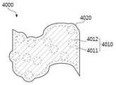
도 4는 본 출원의 또 다른 일 구현 예에 따른 나노 복합체를 예시적으로 나타낸 도면이다. 도 4에 나태난 바와 같이, 본 출원의 또 다른 일 구현 예에 따른 나노 복합체(이하, 제 2 나노 복합체(4000))는 약물(4012)이 담지된 나노 그래핀 산화물(4011)(이하, 제 1 나노 복합체(4010))에 생체 적합성 고분자(4020)를 추가로 포함할 수 있다. 상기 생체 적합성 고분자(4020)는 제 1 나노 복합체(4010)의 외부를 둘러싼 형태로 포함될 수 있다. 예를 들어, 상기 제 2 나노 복합체(4000)는 제 1 나노 복합체(4010) 및 상기 생체 적합성 고분자(4020)가 코어-쉘의 2중 구조를 가지는 입자일 수 있다. 구체적으로, 상기 제 1 나노 복합체(4010)는 나노 그래핀 산화물(4011)에 약물(4012)을 담지시켜 코어를 형성하며, 상기 코어에 생체 적합성 고분자(4020)를 결합시켜 상기 코어를 둘러싸는 쉘을 형성함으로써 제조된 것일 수 있다. 상기에서 「코어」는 상기 2중 구조의 가장 내측에 존재하는 부분을 의미하며, 상기 「쉘」은 상기 코어를 둘러싸며 상기 2중 구조의 최 외측 부분을 의미한다.4 is a diagram illustrating a nanocomposite according to another embodiment of the present application. 4, the nanocomposite (hereinafter, referred to as the second nanocomposite 4000) according to another embodiment of the present application is a nanocomposite comprising a nano-graphene oxide 4011 (hereinafter referred to as " 1 nanocomposite 4010) may further include a biocompatible polymer (4020). The biocompatible polymer (4020) may be contained in the form of surrounding the first nanocomposite (4010). For example, the
또한, 상기에서 「둘러싼다」는 입자의 바깥 표면이 실질적으로 덮이도록 형성되는 것을 의미하며, 상기에서 바깥 표면이 실질적으로 덮이도록 형성되는 것은 예를 들면, 바깥 표면의 50% 이상, 60% 이상, 70% 이상, 80% 이상, 90% 이상, 95% 이상, 또는 99% 이상이 덮이도록 형성되는 것을 의미한다.The term " enclosing " means that the outer surface of the particle is substantially covered, and the outer surface is formed so as to cover substantially 50% or more, 60% or more , 70% or more, 80% or more, 90% or more, 95% or more, or 99% or more.
상기 생체 적합성 고분자(4020)의 종류로는 키토산, 젤라틴, 콜라겐, 폴리-L-라이신, 폴리-L-히스티딘, 폴리-L-아르기닌, 히알루론산, 폴리감마글루탐산, 알지네이트, 카르복시알킬셀룰로오즈, 글리코겐, 아밀로오즈, 덱스트란, 폴리(메트)아크릴산, 플루란, 베타글루칸, 스타치, 히드록시(알킬)셀룰로오즈, 폴리비닐피롤리돈, 폴리에틸렌글리콜, 폴리비닐알콜, 폴리비닐알킬에테르, 폴리아미노알킬(메트)아크릴레이트, 폴리락틱산, 폴리글리콜산, 폴리락틱글리콜산, 폴리카프로락톤, 폴리에틸렌이민 및 이들의 공중합체로 이루어진 군으로부터 선택된 하나 이상을 사용할 수 있다. 하나의 예시에서, 상기 생체 적합성 고분자(4020)의 종류로는 키토산 및 폴리에틸렌글리콜이 공중합된 공중합체를 사용할 수 있다. 상기 제 1 나노 복합체(4010)는 상기 키토산의 아민기에 의해 제타 전위(Zeta Potential)가 더욱 양전하를 나타내도록 할 수 있다. 하나의 예시로서, 상기 약물(4012)의 종류로 독소루비신을 사용하는 경우, 상기 독소루비신이 담지된 나노 그래핀 산화물(4011)을 포함하는 제 1 나노 복합체(4010)는 제타 전위가 0에 가까워 상기 제 1 나노 복합체(4010)들 간에 응집되는 현상이 발생되어 불안정한 분산 상태를 나타낼 수 있다. 따라서, 상기 제 1 나노 복합체(4010)의 분산 안정성을 향상시키기 위하여, 상기 제 2 나노 복합체(4000)는 상기 제 1 나노 복합체(4010)의 외부에 둘러쌀 수 있는 생체 적합성 고분자(4020)를 추가로 포함함으로써, 제타 전위가 더 높은 양전하를 나타내어, 우수한 분산 안정성을 가질 수 있다.Examples of the
본 출원은 또한, 나노 복합체의 제조장치에 관한 것이다. 상기 나노 복합체의 제조장치는 전술한 나노 그래핀 산화물의 제조장치를 통해 제조된 나노 그래핀 산화물을 포함하는 나노 복합체를 제조하기 위한 제조장치에 관한 것으로서, 후술하는 나노 복합체에 대한 구체적인 내용은 상기 나노 그래핀 산화물의 제조장치 및 나노 복합체에서 기술한 내용이 동일하게 적용될 수 있다.The present application also relates to an apparatus for producing nanocomposites. The apparatus for producing a nanocomposite according to the present invention relates to an apparatus for manufacturing a nanocomposite comprising nanograffin oxide produced by the apparatus for manufacturing a nanograffin oxide described above, The same can be applied to the description of the device for producing graphene oxide and the nanocomposite.
도 5는 본 출원의 일 구현예에 따른 나노 복합체의 제조장치를 예시적으로 나타낸 도면이다. 도 5에 나타낸 바와 같이, 상기 나노 복합체의 제조장치는 나노 그래핀 산화물 형성부(5100), 제 1 공급부(5200), 제 2 공급부(5300) 및 제 2 반응조(5400)를 포함한다.5 is a diagram illustrating an apparatus for producing a nanocomposite according to an embodiment of the present application. 5, the nanocomposite manufacturing apparatus includes a nano-graphene
상기 나노 그래핀 산화물 형성부(5100)는 상기 나노 그래핀 산화물의 제조장치에서 기술한 구성 및 내용이 동일하게 적용되므로, 상기 나노 그래핀 산화물 형성부(5100)에 관한 구체적인 설명은 생략하기로 한다.Since the nano-graphene
상기 제 1 공급부(5200)는 상기 나노 그래핀 산화물 형성부(5100)에서 형성된 나노 그래핀 산화물을 공급하는 부분으로서, 상기 제 1 공급부(5200)는 제 1-2 분무장치(5201)를 포함할 수 있다. 상기 나노 그래핀 산화물은 불활성 기체가 흐르는 조건 하에서 상기 제 1-2 분무 장치(5201)를 통해 분무되어, 상기 불활성 기체에 함유된 기체 상태로 제 2 반응조(5400)로 공급된다.The
상기 제 2 공급부(5300)는 약물을 공급하는 부분으로서, 상기 제 2 공급부(5300)는 제 2 분무장치(5301)를 포함할 수 있다. 상기 약물은 용매와 혼합된 액적 상태로 상기 제 2 분무장치(5301)를 통해 분무되어, 제 2 반응조(5400)로 공급될 수 있다.The
상기 용매의 종류는 약물에 따라 결정될 수 있다. 일 구체예에서, 물, 인산염 완충 식염수(PBS), 소 혈청 알부민(Bovine Serum Albumin), 디클로로메탄, 디메틸설폭사이드 또는 에탄올 등을 사용할 수 있으나, 이에 제한되는 것은 아니다.The kind of the solvent can be determined depending on the drug. In one embodiment, water, phosphate buffered saline (PBS), bovine serum albumin, dichloromethane, dimethylsulfoxide or ethanol may be used, but the present invention is not limited thereto.
상기 약물은 용매 1 mL 당 0.1 mg 내지 3 mg으로 공급될 수 있으며, 예를 들어, 0.3 mg 내지 2.5 mg, 0.6 mg 내지 2 mg 또는 0.9 mg 내지 1.5 mg일 수 있으나, 이에 제한되는 것은 아니며, 질병을 가지고 있는 환자의 상태에 따라 전술한 범위 내에서 알맞게 공급될 수 있다.The drug may be supplied at a dose of 0.1 mg to 3 mg per mL of solvent, for example, but may be, but is not limited to, 0.3 mg to 2.5 mg, 0.6 mg to 2 mg or 0.9 mg to 1.5 mg, It can be suitably supplied within the above-described range according to the condition of the patient having the patient.
상기 제 2 반응조(5400)는 나노 복합체를 형성하기 위한 부분으로서, 상기 제 2 반응조(5400)에서는 상기 제 1 공급부(5200) 및 제 2 공급부(5300) 각각에서 공급된 나노 그래핀 산화물 및 약물이 반응하여, 상기 나노 그래핀 산화물에 약물이 담지된 형태의 나노 복합체가 형성될 수 있다. 상기 나노 복합체가 형성되는 내용에 대한 구체적인 설명은 상기 나노 복합체에서 기술한 내용이 동일하게 적용될 수 있으므로, 이를 생략하기로 한다.The
하나의 예시에서, 비록 도면에는 도시되지는 않았지만, 본 출원의 나노 복합체의 제조장치는 용매 제거 수단을 추가로 포함할 수 있다. 상기 용매 제거 수단은 상기 나노 복합체를 용이하게 보관하기 위하여 수행되는 부분으로서, 상기 용매 제거 수단에서는 상기 불활성 기체의 흐름에 따라 제 2 반응조(5400)에서 형성된 나노 복합체를 포함하는 용액으로부터 용매를 제거할 수 있다. 이때, 상기 용매는 상기 제 2 공급부(5300)에 의해 약물과 함께 공급된 용매이다.In one example, although not shown in the drawings, the apparatus for producing a nanocomposite of the present application may further include a solvent removing means. The solvent removing unit removes the solvent from the solution containing the nanocomposite formed in the
상기 용매 제거 수단은 상기 나노 그래핀 산화물의 제조장치에서 기술한 용매 제거 수단이 동일하게 적용될 수 있으므로, 이에 대한 구체적인 설명은 생략하기로 한다.Since the solvent removing means described in the apparatus for producing nano-graphene oxide may be applied in the same manner, a detailed description thereof will be omitted.
또 하나의 예시에서, 본 출원의 나노 복합체의 제조장치는 제 3 반응조(5500)를 추가로 포함할 수 있다. 상기 제 3 반응조(5500)는 나노 복합체의 분산 안정성을 향상시키기 위한 부분으로서, 상기 제 3 반응조(5500)에서는 상기 제 2 반응조(5400)에서 형성된 나노 복합체와 생체 적합성 고분자가 반응하여 상기 나노 복합체의 외부에 상기 생체 적합성 고분자를 형성할 수 있다.In another example, the apparatus for producing a nanocomposite of the present application may further include a
예를 들어, 상기 제 2 반응조(5400)에서 형성된 나노 복합체는 상기 제 3 반응조(5500)로 함침되어, 상기 제 3 반응조(5500) 내에 채워져 있는 생체 적합성 고분자를 포함하는 용액과 상호 작용을 통해, 상기 생체 적합성 고분자가 상기 나노 복합체의 외부에 형성될 수 있다. 이때, 상기 제 2 반응조(5400)에서 형성된 나노 복합체는 불활성 기체가 흐르는 조건 하에서 상기 불활성 기체에 함유된 상태로 상기 제 3 반응조(5500)로 함침될 수 있다.For example, the nanocomposite formed in the
상기 생체 적합성 고분자의 조성 및 상기 나노 복합체의 외부에 생체 적합성 고분자를 형성하는 내용에 관한 구체적인 설명은 상기 나노 복합체에서 기술한 내용이 동일하게 적용될 수 있으므로, 이에 대한 구체적인 설명은 생략하기로 한다.The composition of the biocompatible polymer and the details of forming the biocompatible polymer on the outside of the nanocomposite are the same as those described in the nanocomposite, so a detailed description thereof will be omitted.
또한, 비록 도면에 도시되지는 않았지만, 본 출원의 나노 복합체의 제조장치는 캐리어 기체 공급 시스템(Carrier Air Supply System) 등의 기체 공급 장치와, MFC(Mass Flow Controller) 등의 유량계를 포함할 수 있다. 또한, 상기 기체 공급장치 및 유량계에 의해 상기 나노 그래핀 산화물 형성부(5100), 제 1 공급부(5200), 제 2 공급부(5300) 및 제 2 반응조(5400)는 불활성 기체가 흐르는 조건 하에서 유지될 수 있다. 예를 들어, 상기 불활성 기체는 질소(N2), 헬륨(He), 네온(Ne), 아르곤(Ar), 크립톤(Kr), 제논(Xe) 및 라돈(Rn)으로 이루어진 군으로부터 선택된 하나 이상일 수 있다.Further, although not shown in the drawings, the apparatus for producing a nanocomposite of the present application may include a gas supply device such as a carrier gas supply system and a flow meter such as an MFC (mass flow controller) . The nano-graphene
본 출원의 나노 그래핀 산화물의 제조장치는 공정이 단순하고, 보관 안정성이 우수하며, 그래핀 산화물의 길이 방향 및 두께 방향 모두 나노 크기로 제어할 수 있고, 상기 나노 그래핀 산화물의 제조장치를 통해 제조된 나노 그래핀 산화물을 포함하는 나노 복합체는 큰 비표면적으로 인해 우수한 약물 적재 용량과 광열 치료 효과를 나타낼 수 있다.The apparatus for producing nano-graphene oxide of the present application is simple in process, excellent in storage stability, and can control nano-size both in the longitudinal direction and in the thickness direction of graphene oxide. Nanocomposite nanocomposite nanocomposite nanocomposites produced by the present invention can exhibit excellent drug loading capacity and photothermal therapeutic effect due to large specific surface area.
도 1은 본 출원의 일 구현예에 따른 나노 그래핀 산화물의 제조장치를 예시적으로 나타낸 도면이다.
도 2는 본 출원의 일 실시예에 따른 탄소를 포함하는 제 1 전극 및 금속을 포함하는 제 2 전극으로부터 방전되어 형성된 그래핀 및 금속의 적층 구조를 나타낸 TEM 이미지이다.
도 3은 본 출원의 일 구현예에 따른 나노 복합체를 예시적으로 나타낸 도면이다.
도 4는 본 출원의 또 다른 일 구현 예에 따른 나노 복합체를 예시적으로 나타낸 도면이다.
도 5는 본 출원의 일 구현예에 따른 나노 복합체의 제조장치를 예시적으로 나타낸 도면이다.
도 6은 실시예 3에서 제조된 나노 복합체(nGO@DOX-cPEG)의 생체 적합성 고분자의 함량에 따른 제타 전위(Zeta Potential)를 나타낸 그래프이다.
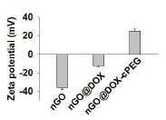
도 7은 각각 실시예 1에서 제조된 나노 그래핀 산화물(nGO), 실시예 1에서 제조된 나노 복합체(nGO@DOX) 및 실시예 3에서 제조된 나노 복합체(nGO@DOX-cPEG)의 제타 전위를 나타낸 그래프이다.
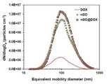
도 8은 각각 실시예 1 및 2에서 제조된 나노 그래핀 산화물 및 나노 복합체의 입자 크기 분포를 나타낸 그래프이다.
도 9는 각각 실시예 1에서 제조된 나노 그래핀 산화물(nGO), DOX 및 실시예 1에서 제조된 나노 복합체(nGO@DOX)의 분산성을 나타낸 디지털 이미지이다.
도 10은 실시예 1에서 제조된 나노 복합체(nGO@DOX) 및 실시예 3에서 제조된 나노 복합체(nGO@DOX-cPEG)의 분산성을 나타낸 디지털 이미지이다.
도 11은 실시예 1에서 제조된 나노 그래핀 산화물(nGO) 및 비교예 1에서 구입한 마이크로 그래핀 산화물(mGO) 박편(Flake)의 분산성을 나타낸 디지털 이미지이다.
도 12 및 13은 각각 인산염 완충 식염수(PBS) 및 10%의 소태아혈청(FBS)이 보충된 Dulbecco's 변형 이글 배지(DMEM Carlsbad, USA)에서 저장 기간에 따라 각각 측정된 실시예 1에서 제조된 나노 복합체(nGO@DOX) 및 실시예 3에서 제조된 나노 복합체(nGO@DOX-cPEG)의 입자 크기를 나타낸 그래프이다.
도 14는 UV-vis 분광 광도계(UV-vis spectroscopy)를 이용하여 각각 실시예 1에서 제조된 나노 그래핀 산화물(nGO), DOX 및 실시예 1에서 제조된 나노 복합체(nGO@DOX)를 분석한 그래프이다.
도 15는 각각 실시예 1에서 제조된 나노 그래핀 산화물(nGO), 실시예 1에서 제조된 나노 복합체(nGO@DOX) 및 실시예 3에서 제조된 나노 복합체(nGO@DOX-cPEG)의 투과 전자 현미경(TEM) 이미지이다.
도 16은 각각 실시예 1에서 제조된 나노 그래핀 산화물(nGO) 및 실시예 3에서 제조된 나노 복합체(nGO@DOX-cPEG)의 원자력 현미경(AFM) 이미지이다.
도 17은 각각 실시예 1에서 제조된 나노 그래핀 산화물(nGO), 실시예 1에서 제조된 나노 복합체(nGO@DOX) 및 실시예 3에서 제조된 나노 복합체(nGO@DOX-cPEG)의 두께 방향 및 길이 방향 크기를 나타낸 그래프이다.
도 18은 각각 실시예 1에서 제조된 건조된 상태의 나노 그래핀 산화물(nGO), DOX 및 실시예 1에서 제조된 나노 복합체(nGO@DOX)의 푸리에 변환 적외선(FTIR) 측정을 나타낸 그래프이다.
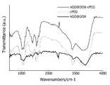
도 19는 실시예 1에서 제조된 나노 복합체(nGO@DOX) 및 실시예 3에서 제조된 나노 복합체(nGO@DOX-cPEG)의 푸리에 변환 적외선(FTIR) 분석을 나타낸 그래프이다.
도 20은 실시예 1에서 제조된 나노 복합체(nGO@DOX)에서, nGO 박편(Flake)의 DOX의 포집 효율(EE) 및 적재 용량(LC)을 나타낸 그래프이다.
도 21은 실시예 3에서 제조된 나노 복합체(nGO@DOX-cPEG)의 DOX의 포집 효율(EE) 및 적재 용량(LC)을 나타낸 그래프이다.
도 22는 각각 실시예 1에서 제조된 나노 그래핀 산화물(nGO) 및 비교예 1에서 구입한 마이크로 그래핀 산화물(mGO)의 흡착 등온선 그래프 및 상기 각각 실시예 1에서 제조된 나노 그래핀 산화물(nGO) 및 비교예 1에서 구입한 마이크로 그래핀 산화물(mGO)의 BET 표면적, 기공 부피 및 기공 크기를 나타낸 표이다.
도 23은 실시예 3에서 제조된 나노 복합체(nGO@DOX-cPEG)의 pH 조건(p < 0.01)에 따른 DOX의 시험관 내(In vitro) 방출 프로필을 나타낸 그래프이다.
도 24는 실시예 2에서 탄소-철(Fe) 스파크 방전에 의해 제조된 nGO를 포함하는 nGO@DOX 박편 및 비교예 4에서 탄소-탄소 스파크 방출에 의해 제조된 nGO를 포함하는 nGO@DOX 박편의 DOX 방출 결과를 나타낸 도면이다.
도 25는 각각 근적외선을 조사하거나, 조사하지 않은 실시예 3에서 제조된 나노 복합체(nGO@DOX-cPEG) 및 비교예 3에서 제조된 나노 복합체(nGO@cPEG)로 치료한 전립선 암세포인 PC3, DU145 및 LNCaP 세포의 생존률을 나타낸 그래프이다(a: p< 0.05; b: p< 0.01; c: p< 0.05).
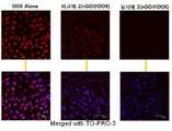
도 26은 실시예 3에서 제조된 나노 복합체(nGO@DOX-cPEG)의 치료에 따른 PC3, DU145 및 LNCaP 세포의 공 초점(Confocal) 이미지이다.
도 27은 실시예 3에서 제조된 나노 복합체(nGO@DOX-cPEG)의 FACS를 사용하여 정량적인 세포질 흡수를 측정한 그래프이다.
도 28은 실시예 1에서 제조된 나노 그래핀 산화물(nGO@DOX) 및 실시예 3에서 제조된 나노 복합체(nGO@DOX-cPEG) 분산액의 근적외선 조사 시간에 따른 온도 변화를 나타낸 도면이다.
도 29는 각각 근적외선을 조사하거나, 조사하지 않은 실시예 3에서 제조된 나노 복합체(nGO@DOX-cPEG) 및 비교예 3에서 제조된 나노 복합체(nGO@cPEG)의 치료에 따른 전립선 암 세포의 세포 자멸 효과(Apoptotic effects)를 나타낸 그래프이다.
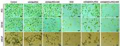
도 30은 각각 근적외선을 조사하거나 조사하지 않은 실시예 3에서 제조된 나노 복합체(nGO@DOX-cPEG) 및 비교예 3에서 제조된 나노 복합체(nGO@cPEG)의 치료에 따른 PC3, DU145 및 LNCaP 세포의 생사 분석을 나타낸 이미지이다(스케일 바: 100 ㎛).
도 31은 각각 근적외선을 조사하거나 조사하지 않은 실시예 3에서 제조된 나노 복합체(nGO@DOX-cPEG) 및 비교예 3에서 제조된(nGO@cPEG) 박편의 치료에 따른 PC3, DU145 및 LNCaP 세포의 주기 분석을 나타낸 이미지이다(스케일 바: 100 ㎛).
도 32는 각각 근적외선을 조사하거나, 조사하지 않은 실시예 3에서 제조된 나노 복합체(nGO@DOX-cPEG)의 치료에 따른 전립선 암 세포에 의한 세포 자멸 관련 단백질의 발현을 확인하기 위한 웨스턴 블롯(Western Blot) 분석을 나타낸 도면이다.
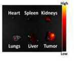
도 33은 PC3 종양 이종 이식 쥐(원형은 종양 영역을 나타냄)의 생체 내 실시예 3에서 제조된 nGO@Cy5.5-cPEG의 생체 분포를 나타낸 이미지이다.
도 34는 Cy5.5의 개별 장기 추출 윤곽(농도 분포)을 나타낸 이미지이다.
도 35는 nGO@Cy5.5-cPEG의 개별 장기 추출 윤곽(농도 분포)을 나타낸 이미지이다.
도 36은 식염수 또는 실시예 3에서 제조된 나노 복합체(nGO@DOX-cPEG)로 전처리된 쥐들의 종양의 근적외선 레이저 조사 시간에 따른 생체 내 광열 이미징을 나타낸다.
도 37은 PC3 종양 보유 BALB/c 실험 쥐들에 각각 근적외선을 조사하거나 조사하지 않은 실시예 3에서 제조된 나노 복합체(nGO@DOX-cPEG)의 정맥 투여 기간에 따른 종양 부피를 나타낸 그래프이다(각 샘플은 3 일 간격으로 3 회 투여했다 (*p < 0.05, **p < 0.01, ***p < 0.001)).
도 38은 PC3 종양 보유 BALB/c 실험 쥐들에 각각 근적외선을 조사하거나 조사하지 않은 실시예 3에서 제조된 나노 복합체(nGO@DOX-cPEG)의 정맥 투여 기간에 따른 체중을 나타낸 그래프이다(각 샘플은 3 일 간격으로 3 회 투여했다 (*p < 0.05, **p < 0.01, ***p < 0.001)).
도 39는 각각 근적외선을 조사하거나 조사하지 않은 실시예 3에서 제조된 나노 복합체(nGO@DOX-cPEG)의 치료에 따른 종양의 조직 병리학적 및 조직 화학적 분석을 나타낸 도면이다.1 is a diagram illustrating an apparatus for producing a nano-graphene oxide according to an embodiment of the present application.
FIG. 2 is a TEM image showing a stacked structure of a first electrode including carbon and a second electrode including a metal and formed by discharging a graphene and a metal according to an embodiment of the present invention. FIG.
Figure 3 is an illustration of a nanocomposite according to one embodiment of the present application.
4 is a diagram illustrating a nanocomposite according to another embodiment of the present application.
5 is a diagram illustrating an apparatus for producing a nanocomposite according to an embodiment of the present application.
FIG. 6 is a graph showing the zeta potential (Zeta Potential) according to the content of the biocompatible polymer of the nanocomposite (nGO @ DOX-cPEG) prepared in Example 3. FIG.
7 shows the zeta potential of the nano-graphene oxide (nGO) prepared in Example 1, the nanocomposite (nGO @ DOX) prepared in Example 1 and the nanocomposite (nGO @ DOX-cPEG) Fig.
8 is a graph showing the particle size distribution of the nano-graphite oxide and nanocomposite prepared in Examples 1 and 2, respectively.
9 is a digital image showing the dispersibility of the nano-graphene oxide (nGO), DOX, and nano-composite (nGO @ DOX) prepared in Example 1, respectively,
10 is a digital image showing the dispersibility of the nanocomposite (nGO @ DOX) prepared in Example 1 and the nanocomposite (nGO @ DOX-cPEG) prepared in Example 3. Fig.
11 is a digital image showing the dispersibility of the nano-graphene oxide (nGO) prepared in Example 1 and the micrographite oxide (mGO) flake (Flake) obtained in Comparative Example 1. Fig.
Figures 12 and 13 are graphs showing the effect of the nano-particles prepared in Example 1, measured in the storage period, on Dulbecco's modified Eagle's medium (DMEM Carlsbad, USA) supplemented with phosphate buffered saline (PBS) and 10% fetal bovine serum (NGO @ DOX) and the nanocomposite prepared in Example 3 (nGO @ DOX-cPEG).
Figure 14 shows the results of analysis of nano-graphite oxide (nGO), DOX and nano-composite (nGO @ DOX) prepared in Example 1, respectively, prepared in Example 1 using UV-vis spectroscopy Graph.
FIG. 15 is a graph showing the transmittance of the nano-graphene oxide (nGO) prepared in Example 1, the nanocomposite (nGO @ DOX) prepared in Example 1 and the nanocomposite (nGO @ DOX-cPEG) It is a microscopic (TEM) image.
16 is an atomic force microscope (AFM) image of the nano-graphene oxide (nGO) prepared in Example 1 and the nanocomposite (nGO @ DOX-cPEG) prepared in Example 3, respectively.
17 is a graph showing the relationship between the thickness of the nano-graphene oxide (nGO) prepared in Example 1, the nanocomposite (nGO @ DOX) prepared in Example 1 and the nanocomposite (nGO @ DOX-cPEG) And the longitudinal size.
18 is a graph showing Fourier Transform Infrared (FTIR) measurements of the dried nano-graphene oxide (nGO), DOX and the nanocomposite (nGO @ DOX) prepared in Example 1, respectively, prepared in Example 1. Fig.
19 is a graph showing Fourier transform infrared (FTIR) analysis of the nanocomposite (nGO @ DOX) prepared in Example 1 and the nanocomposite (nGO @ DOX-cPEG) prepared in Example 3.
20 is a graph showing the collection efficiency (EE) and the loading capacity (LC) of DOX of nGO flakes (nGO @ DOX) prepared in Example 1. Fig.
21 is a graph showing the collection efficiency (EE) and the loading capacity (LC) of DOX of the nanocomposite (nGO @ DOX-cPEG) prepared in Example 3. Fig.
22 is a graph showing the adsorption isotherms of the nano-graphene oxide (nGO) prepared in Example 1 and the micrographite oxide (mGO) obtained in Comparative Example 1, and the nano-graphite oxide (nGO ) And the micrographite oxide (mGO) purchased in Comparative Example 1 are shown in Table 1, which shows the BET surface area, pore volume and pore size.
23 is a graph showing the in vitro release profile of DOX according to the pH condition (p < 0.01) of the nanocomposite (nGO @ DOX-cPEG) prepared in Example 3. Fig.
FIG. 24 is a graph of the nGO @ DOX flake containing nGO produced by carbon-iron (Fe) spark discharge in Example 2 and the nGO @ DOX flake containing nGO produced by carbon- DOX emission results.
Fig. 25 is a graph showing the results of a comparison between prostate cancer cells PC3 and DU145 treated with the nanocomposite (nGO @ DOX-cPEG) prepared in Example 3 and the nanocomposite (nGO @ cPEG) prepared in Comparative Example 3, (A: p <0.05; b: p <0.01; c: p < 0.05).
26 is a confocal image of PC3, DU145, and LNCaP cells upon treatment of the nanocomposite (nGO @ DOX-cPEG) prepared in Example 3. Fig.
27 is a graph showing quantitative cytoplasmic absorption measurement using FACS of the nanocomposite (nGO @ DOX-cPEG) prepared in Example 3. Fig.
28 is a graph showing a temperature change of the nano-graphene oxide (nGO @ DOX) prepared in Example 1 and the nanocomposite (nGO @ DOX-cPEG) dispersion prepared in Example 3 with the irradiation time of near infrared rays.
FIG. 29 is a graph showing the results of measurement of the activity of the cells of prostate cancer cells according to the treatment of the nanocomposite (nGO @ DOX-cPEG) prepared in Example 3 and the nanocomposite (nGO @ cPEG) prepared in Comparative Example 3, This is a graph showing apoptotic effects.
FIG. 30 shows the results of the treatment of PC3, DU145 and LNCaP cells (nGO @ cPEG) according to the treatment of the nanocomposite (nGO @ DOX-cPEG) prepared in Example 3 and the nanocomposite (Scale bar: 100 mu m).
31 is a graph showing the effect of treatment of PC3, DU145 and LNCaP cells on the treatment of nanocomposite (nGO @ DOX-cPEG) prepared in Example 3 and nGO @ cPEG flakes prepared in Comparative Example 3, (Scale bar: 100 mu m).
32 is a graph showing the results of Western blotting (Western blot analysis) for confirming the expression of apoptosis-related proteins by prostate cancer cells according to treatment of nanocomposite (nGO @ DOX-cPEG) prepared in Example 3 irradiated with near- Blot analysis.
33 is an image showing the biodistribution of nGO@Cy5.5-cPEG prepared in Example 3 in vivo of a PC3 tumor xenograft mouse (the circle indicates a tumor area).
34 is an image showing an individual organ extraction outline (concentration distribution) of Cy5.5.
35 is an image showing the individual organ extraction outline (concentration distribution) of nGO@Cy5.5-cPEG.
Figure 36 shows in vivo photothermal imaging of the tumors of rats pretreated with saline or the nanocomposite prepared in Example 3 (nGO @ DOX-cPEG) according to near infrared laser irradiation time.
37 is a graph showing the tumor volume according to the intravenous administration period of the nanocomposite (nGO @ DOX-cPEG) prepared in Example 3 in which the PC3 tumor bearing BALB / c experimental rats were irradiated or not irradiated with near infrared rays (* P <0.05, ** p <0.01, *** p <0.001) at 3-day intervals.
38 is a graph showing the body weight of the PC3 tumor-bearing BALB / c mice according to the intravenous administration period of the nanocomposite (nGO @ DOX-cPEG) prepared in Example 3 in which the near infrared rays were not irradiated or irradiated, respectively (P < 0.05, ** p < 0.01, *** p < 0.001).
39 is a diagram showing histopathological and histochemical analysis of tumors according to the treatment of the nanocomposite (nGO @ DOX-cPEG) prepared in Example 3, which is not irradiated or irradiated with near infrared rays, respectively.
이하 실시예 및 비교예를 통하여 상기 기술한 내용을 보다 구체적으로 설명하지만, 본 출원의 범위가 하기 제시된 내용에 의해 제한되는 것은 아니다.Hereinafter, the present invention will be described in more detail with reference to Examples and Comparative Examples. However, the scope of the present application is not limited by the following description.
실시예 1Example 1
나노 그래핀 산화물(nGO)의 제조Preparation of nano-graphene oxide (nGO)
도 1과 같이, 탄소로 이루어진 제 1 전극(C-072561, Nilaco, Japan) 및 상기 탄소로 이루어진 제 1 전극 내에 철(Fe)이 함유된 제 2 전극으로부터 스파크 방전을 통해 흑연(Graphite) 나노 입자를 생성하고, 상기 흑연 나노 입자는 질소 가스(99.9999% 순도, 3 L/min)에 의해 제 1 반응조로 운반되었다. 상기 방전 구성의 사양은 상기 제 1 전극 및 제 2 전극의 직경 및 길이가 각각 3 mm 및 100 mm이고, 저항이 0.5 MΩ이며, 전기 용량이 1.0 nF이고, 적재 전류(Loading Current)가 2.0 mA이며, 인가 전압이 3.0 kV이고, 주파수가 667 Hz이다.1, a graphite nanoparticle (C-072561, Nilaco, Japan) was formed through spark discharge from a first electrode (C-072561, Nilaco, Japan) made of carbon and a second electrode containing iron And the graphite nanoparticles were transferred to the first reactor by nitrogen gas (99.9999% purity, 3 L / min). The specifications of the discharge configuration were as follows: the first electrode and the second electrode had a diameter and a length of 3 mm and 100 mm, a resistance of 0.5 MΩ, a capacitance of 1.0 nF, a loading current of 2.0 mA, , The applied voltage is 3.0 kV, and the frequency is 667 Hz.
단순화된 Hummer's 법을 이용하여, 제 1 반응조에 포함된 용액 내에 흑연 입자를 수집하기 위하여 초음파 탐침을 사용하였고, 이어서, 나노 그래핀 산화물(nGO)을 형성하기 위해 상기 흑연 입자와 용액을 반응시켰다. 제 1 반응조에서 단순화된 Hummer's 법에 의해 형성된 액체 용액의 계면에 상기 질소 가스에 상기 흑연 입자가 함유된 기체 흐름이 도달했을 때, 상기 기체 흐름에 250 W/cm2 강도의 초음파가 조사되었다. 40 mL의 H2SO4 및 1.8 g의 KMnO4와 nGO의 전구체로서 작용한 흑연 입자의 산화에 의해 nGO를 수득하였다. 제 1 반응조에서 nGO를 형성하기 위하여, 흑연 입자의 체류 시간은 3.8 분으로 설정하였다.Using the simplified Hummer's method, an ultrasonic probe was used to collect the graphite particles in the solution contained in the first reaction vessel, and then the solution was reacted with the graphite particles to form nano-graphite oxide (nGO). When the gas flow containing the graphite particles reached the nitrogen gas at the interface of the liquid solution formed by the simplified Hummer's method in the first reaction tank, the gas flow was irradiated with ultrasound of 250 W / cm2 intensity. 40 mg of H2 SO4 and 1.8 g of KMnO4 and nGO were obtained by oxidation of graphite particles acting as precursors of nGO. In order to form nGO in the first reaction vessel, the residence time of the graphite particles was set to 3.8 minutes.
연동 펌프(323Du/MC4, Watson-Marlow Bredel Pump, 미국)를 사용하여 제 1-1 분무장치의 저장부에 nGO가 함유된 용액을 주사하였다. nGO 액적을 형성하기 위하여, 펌프에 의해 공급된 nGO 용액을 분무하기 위한 작동 가스로서, 또 다른 질소 가스 흐름이 사용되었다. 그 후, 상기 액적은 활성화된 탄소 펠릿 및 실리카 겔을 포함하는 디누더(Denuder)를 통과시켜 건조된 nGO를 제조하였다.Using a peristaltic pump (323Du / MC4, Watson-Marlow Bredel Pump, USA), a solution containing nGO was injected into the reservoir of the 1-1 spraying apparatus. In order to form the nGO droplet, another nitrogen gas flow was used as the working gas for atomizing the nGO solution supplied by the pump. The droplets were then passed through a Denuder containing activated carbon pellets and silica gel to produce dried nGO.
나노 복합체(nGO@DOX)의 제조Preparation of nanocomposite (nGO @ DOX)
상기 실시예 1에서 제조된 nGO를 함유하는 흐름을 직접 사용하여, 질소 가스 흐름 하에 에탄올 1 mL 당 DOX(1225703, Sigma-Aldrich, USA) 1 mg을 포함하는 용액을 추가로 분무하였다. 그런 다음, 90℃의 벽 온도를 가지는 가열 관형 반응기(Heated tubular reactor)에 nGO@DOX 하이브리드 액적을 통과시켜 용매를 추출하여 nGO@DOX 박편(Flake)을 제조하였다.A solution containing 1 mg of DOX (1225703, Sigma-Aldrich, USA) per 1 mL of ethanol was further sprayed under nitrogen gas flow using the nGO containing stream prepared in Example 1 directly. Then, nGO @ DOX flakes were prepared by passing a nGO @ DOX hybrid droplet through a heated tubular reactor having a wall temperature of 90 DEG C to extract the solvent.
실시예 2Example 2
나노 그래핀 산화물(nGO)의 제조Preparation of nano-graphene oxide (nGO)
철(Fe)로 이루어진 제 2 전극을 사용한 것을 제외하고, 실시예 1과 동일한 방식으로 nGO를 제조하였다.NGO was produced in the same manner as in Example 1, except that the second electrode made of iron (Fe) was used.
나노 복합체(nGO@DOX)의 제조Preparation of nanocomposite (nGO @ DOX)
상기 실시예 2에서 제조된 nGO를 사용한 것을 제외하고, 실시예 1과 동일한 방식으로 nGO@DOX 박편을 제조하였다.NGO @ DOX flakes were prepared in the same manner as in Example 1, except that the nGO prepared in Example 2 was used.
실시예 3Example 3
나노 복합체(nGO@DOX-cPEG)의 제조Preparation of nanocomposite (nGO @ DOX-cPEG)
상기 실시예 1에서 제조된 nGO@DOX 박편은 DOX가 수성 분산성 유지에 관여하는 nGO 표면의 OH, COOH 및 C=O를 포함하는 산소 함유 관능기를 덮어 응집되는 경향을 나타내므로, 상기 실시예 1에서 제조된 nGO@DOX 박편을 증류수에 키토산(21161, Polysciences社)과 폴리에틸렌글리콜(81210, Sigma-Aldrich 社)이 0.65:0.35의 함량비로 컨주게이션(Conjugation)된 cPEG가 혼합된 용액에 첨가한 다음 5분 동안 볼텍싱(Vortexing) 및 초음파 처리함으로써, 분산 안정성이 향상된 nGO@DOX-cPEG 박편을 제조하였다.The nGO @ DOX flakes prepared in Example 1 exhibited a tendency that DOX tended to cover the oxygen-containing functional groups containing OH, COOH and C = O on the surface of nGO participating in the aqueous dispersion maintenance, The nGO @ DOX flakes prepared in Example 1 were added to a mixed solution of chitosan (21161, Polysciences) and polyethylene glycol (81210, Sigma-Aldrich) at a ratio of 0.65: 0.35 in cPEG mixed with distilled water The nGO @ DOX-cPEG flakes with improved dispersion stability were prepared by vortexing and sonication for 5 minutes.
이러한, 결합은 대식세포(Macrophage) 옵소닌작용(Opsonization)을 최소화하고, 종양 영역으로 효과적인 전달을 위한 혈액 순환 시간을 증가시킬 수 있다. 제타 전위 측정으로부터, 이 조건에서 전하 역전이 최대화되었기 때문에, nGO@DOX 박편(Flake)을 효과적으로 덮기 위하여 cPEG의 함량으로 20 w/w%를 선택하였다. 도 6에 나타낸 바와 같이, 상기 20 w/w% 이상에서 제타 전위 값의 큰 증가가 없음을 알 수 있었다. 도 7에 나타낸 바와 같이, DOX가 nGO 박편(Flake)의 산소 함유 관능기를 부동태화(Passivate)시키기 때문에, nGO 박편(Flake)의 음전위는 DOX와 결합시 감소되었다. 또한, DOX의 아민기는 nGO 표면의 음전하를 중성화시킬 수 있다. cPEG 결합은 nGO@DOX 박편(Flake)의 제타 전위를 더욱 양극성으로 변화시켰고, 이는 키토산 메트릭스의 아민기가 추가적으로 결합되었기 때문이다.Such binding may minimize macrophage opsonization and increase blood circulation time for effective delivery to the tumor area. From the zeta potential measurements, 20% w / w was chosen as the content of cPEG to effectively cover the nGO @ DOX flakes, since charge reversal was maximized under these conditions. As shown in FIG. 6, it was found that there was no large increase in the zeta potential value above 20 w / w%. As shown in Fig. 7, since the DOX passivates the oxygen-containing functional group of the nGO flake (flake), the negative potential of the nGO flake (Flake) was reduced upon binding with DOX. In addition, the amine group of DOX can neutralize the negative charge on the nGO surface. The cPEG binding changed the zeta potential of the nGO @ DOX flake (Flake) to more polar, because the amine groups of the chitosan matrix were further bound.
비교예 1Comparative Example 1
마이크로 그래핀 산화물(mGO)Micrographite oxide (mGO)
습식 합성으로 제조되어, 물 1 mL 당 0.5 mg의 흑연이 분산된 mGO(D10, Graphenea) 분산액을 상업적으로 구입하였다.A mGO (D10, Graphenea) dispersion, prepared by wet synthesis, in which 0.5 mg of graphite per mL of water was dispersed was commercially available.
비교예 2Comparative Example 2
마이크로 복합체(mGO@DOX)의 제조Preparation of microcomposite (mGO @ DOX)
상기 비교예 1에서 구입한 mGO 분산액을 사용한 것을 제외하고, 실시예 1과 동일한 방식으로 mGO@DOX를 제조하였다.MGO @ DOX was prepared in the same manner as in Example 1, except that the mGO dispersion obtained in Comparative Example 1 was used.
비교예 3Comparative Example 3
나노 복합체(nGO@cPEG)의 제조Preparation of nanocomposite (nGO @ cPEG)
상기 실시예 1에서 제조된 nGO를 증류수에 키토산(21161, Polysciences社)과 폴리에틸렌글리콜(81210, Sigma-Aldrich 社)이 0.65:0.35의 함량비로 컨주게이션(Conjugation)된 cPEG가 혼합된 용액에 첨가한 다음 5분 동안 볼텍싱(Vortexing) 및 초음파 처리함으로써, nGO@cPEG 박편을 제조하였다.The nGO prepared in Example 1 was added to a mixed solution of chitosan (21161, Polysciences) and polyethylene glycol (81210, Sigma-Aldrich) at a ratio of 0.65: 0.35 in distilled water to cGEG conjugated The nGO @ cPEG flakes were prepared by vortexing and sonication for the next 5 minutes.
비교예 4Comparative Example 4
나노 그래핀 산화물(nGO)의 제조Preparation of nano-graphene oxide (nGO)
제 1 전극 및 제 2 전극 모두 탄소로 이루어진 전극(C-072561, Nilaco, Japan)을 사용한 것을 제외하고, 실시예 1과 동일한 방식으로 nGO를 제조하였다.NGO was prepared in the same manner as in Example 1, except that an electrode (C-072561, Nilaco, Japan) made of carbon was used for both the first electrode and the second electrode.
나노 복합체(nGO@DOX)의 제조Preparation of nanocomposite (nGO @ DOX)
상기 비교예 4에서 제조된 nGO를 사용한 것을 제외하고, 실시예 1과 동일한 방식으로 nGO@DOX 박편(Flake)을 제조하였다.NGO @ DOX flakes were prepared in the same manner as in Example 1, except that the nGO prepared in Comparative Example 4 was used.
실험예- 나노 그래핀 산화물 및 나노 복합체의 특성 평가Experimental Example - Characterization of nano-graphene oxide and nanocomposite
<입자 크기 분포 및 물리 화학 특성 분석>≪ Analysis of particle size distribution and physical <
도 8은 실시예 1 및 2 각각에서 제조된 나노 그래핀 산화물(nGO) 및 나노 복합체(nGO@DOX)의 입자 크기 분포를 나타낸 그래프이다. 상기 실시예 1 및 2 각각에서 제조된 나노 복합체(nGO@DOX)의 크기 분포를 평가하기 위하여, 주사 이동성 입도 측정기(SMPS, 3936, TSI, USA)를 사용하여 기하 평균 직경(Geometric Mean Diameter), 기하 표준 편차(Geometric Standard Deviation) 및 총 수 농도(Total Number Concentration)를 측정하여 하기 표 1에 나타내었다.8 is a graph showing the particle size distribution of the nano-graphene oxide (nGO) and nanocomposite (nGO @ DOX) prepared in Examples 1 and 2, respectively. To evaluate the size distribution of the nanocomposite (nGO @ DOX) prepared in each of Examples 1 and 2, a geometric mean diameter (Diameter) was measured using a scanning mobile particle size analyzer (SMPS, 3936, TSI, USA) Geometric Standard Deviation and Total Number Concentration were measured and are shown in Table 1 below.
(nm)Geometric mean diameter
(nm)
(-)Geometric standard deviation
(-)
(cm-3)Total concentration
(cm-3 )
상기 표 1에 나타낸 바와 같이, 실시예 1에서 제조된 nGO 박편(Flake)의 기하 평균 직경, 기하 표준 편차 및 총 수 농도는 각각 108.5 nm, 1.81 및 6.6 × 106 cm-3이었고, DOX 입자의 기하 평균 직경, 기하 표준 편차 및 총 수 농도는 각각 94.0 nm, 1.79 및 1.5 × 106 cm-3이었다.As shown in Table 1, the geometric mean diameter, geometric standard deviation, and total number density of the nGO flakes (Flake) prepared in Example 1 were 108.5 nm, 1.81 and 6.6 × 106 cm-3 , respectively, Geometric mean diameter, geometric standard deviation and total number concentration were 94.0 nm, 1.79 and 1.5 × 106 cm-3 , respectively.
nGO@DOX 박편(Flake)은 하이브리드 액적으로부터 용매 추출 동안 nGO 표면에 DOX 성분의 증착으로 인해 nGO 박편(Flake)보다 기하 평균 직경 및 총 수 농도가 컸다. 분무기 오리피스를 통과한 하이브리드 액적의 압력, 속도 및 밀도와 같은 기계적 성질은 크게 변화되었다. 이로 인하여 nGO 표면에 DOX 입자가 재분배되었기 때문에 DOX 결합 후 nGO 박편(Flake)의 크기가 크게 증가하지 않았다. 새로 형성된 피크, 즉, 다중 모드의 크기 분포는 없었다. 이 분포는 DOX가 아닌 개별 nGO의 분포를 따랐고, 이는, nGO 박편(Flake)의 수 농도가 자가 조립 동안 모든 DOX 입자를 담지하기에 충분하다는 것을 나타냈다.The nGO @ DOX flakes (Flake) had larger geometric mean diameter and total number concentration than nGO flakes due to the deposition of DOX components on the nGO surface during solvent extraction from the hybrid droplets. The mechanical properties such as pressure, velocity and density of the hybrid droplets passing through the sprayer orifice have changed significantly. Because of this, DOX particles were redistributed on the nGO surface, so the size of nGO flakes after DOX bonding did not increase significantly. There was no newly formed peak, that is, the size distribution of the multimode. This distribution followed the distribution of individual nGOs rather than DOX, indicating that the number concentration of nGO flakes was sufficient to support all DOX particles during self-assembly.
또한, 실시예 1에서 제조된 nGO@DOX, 실시예 3에서 제조된 nGO@DOX-cPEG 및 비교예 1에서 구입한 mGO 박편(Flake)의 물리 화학 특성 분석을 수행하였다. 도 9는 실시예 1에서 제조된 nGO, DOX 및 실시예 1에서 제조된 nGO@DOX 박편(Flake)의 분산성을 나타낸 디지털 이미지이고, 도 10은 실시예 1에서 제조된 nGO@DOX와 실시예 3에서 제조된 nGO@DOX-cPEG 박편(Flake)의 분산성을 나타낸 디지털 이미지이다. 도 9 및 도 10에 나타낸 바와 같이, 육안 검사를 통해 DOX가 붉은색을 나타내므로, nGO 박편에 DOX의 단일 경로 주입(Single Pass Load)이 가능함을 확인할 수 있었다. 또한, 도 11은 실시예 1에서 제조된 nGO 및 비교예 1에서 구입한 mGO 박편(Flake)의 분산성을 나타낸 디지털 이미지이다. 도 11에 나타낸 바와 같이, 실시예 1에서 기상 합성에 의해 제조된 nGO는 투명색을 나타내고, 비교예 1에서 습식 합성에 의해 제조된 mGO는 불투명색을 나타내므로, 기상 합성에 의해 nGO를 제조하는 경우, 습식 합성에 의해 mGO를 제조하는 경우에 비해 상대적으로 분산성이 우수한 것을 확인할 수 있다.In addition, the physicochemical properties of nGO @ DOX prepared in Example 1, nGO @ DOX-cPEG prepared in Example 3, and mGO flake purchased in Comparative Example 1 were analyzed. FIG. 9 is a digital image showing the dispersibility of nGO, DOX, and nGO @ DOX flakes (Flake) prepared in Example 1, and FIG. 10 is a digital image showing the dispersibility of nGO @ 3 is a digital image showing the dispersibility of nGO @ DOX-cPEG flakes (Flake) As shown in FIG. 9 and FIG. 10, since the DOX shows a red color through visual inspection, it can be confirmed that single pass loading of DOX is possible in nGO flakes. 11 is a digital image showing the dispersibility of the nGO produced in Example 1 and the mGO flake (Flake) obtained in Comparative Example 1. Fig. As shown in Fig. 11, nGO produced by vapor phase synthesis in Example 1 exhibits a transparent color, and mGO produced by wet synthesis in Comparative Example 1 exhibits opaque color. Therefore, when nGO is produced by gas phase synthesis, It can be confirmed that the dispersibility is relatively superior to that in the case of producing mGO by wet synthesis.
또한, 도 12 및 13은 각각 인산염 완충 식염수(PBS) 및 10%의 소태아혈청(FBS)이 보충된 Dulbecco's 변형 이글 배지(DMEM Carlsbad, USA)에서 저장 기간에 따라 각각 측정한 실시예 1에서 제조된 nGO@DOX 및 실시예 3에서 제조된 nGO@DOX-cPEG 박편(Flake)의 입자 크기를 나타낸 그래프이다. 도 12 및 13 각각에 나타낸 바와 같이, 실시예 1에서 제조된 nGO@DOX 박편(Flake)은 응집을 나타냈다. 실시예 3에서 제조된 nGO@DOX-cPEG 박편(Flake)은 cPEG 결합을 통해 불안정성이 완화되었다. 동일한 극성 표면 사이에 정전기적 반발력을 도입함으로써, nGO@DOX 박편(Flake)의 표면을 부동태화시켜 장기 보관을 위한 안정성이 유지됨을 확인할 수 있었다.Figures 12 and 13 also show the results obtained in Example 1, measured in terms of storage time, in Dulbecco's modified Eagle's medium (DMEM Carlsbad, USA) supplemented with phosphate buffered saline (PBS) and 10% fetal bovine serum And nGO @ DOX-cPEG flakes prepared in Example 3 (Flake). As shown in Figures 12 and 13, respectively, the nGO @ DOX flakes (Flake) prepared in Example 1 exhibited flocculation. The nGO @ DOX-cPEG flake (Flake) prepared in Example 3 was relieved of instability through cPEG binding. By introducing an electrostatic repulsive force between the same polarity surfaces, it was confirmed that stability for long-term storage was maintained by passivating the surface of nGO @ DOX flakes.
<광 흡수 특성 분석>≪ Analysis of light absorption characteristics &
실시예 1에서 제조된 nGO@DOX 박편(Flake)의 nGO 박편(Flake) 상에 DOX의 적재를 확인하기 위하여 UV-vis 분광 광도계(U-2800, PerkinElmer, USA)를 사용하여 광 흡수 특성을 분석하였다.Optical absorption characteristics were analyzed using a UV-vis spectrophotometer (U-2800, PerkinElmer, USA) to confirm the loading of DOX on the nGO flakes of nGO @ DOX flakes prepared in Example 1 Respectively.
도 14는 UV-vis 분광 광도계(UV-vis spectroscopy)를 이용하여 각각 실시예 1에서 제조된 나노 그래핀 산화물(nGO), DOX 및 실시예 1에서 제조된 나노 복합체(nGO@DOX)를 분석한 그래프이다. 도 14에 나타낸 바와 같이, nGO에 대한 232 nm에서의 강한 흡수 피크 및 302 nm에서의 숄더 피크(Shoulder Peak)는 각각 C=C 및 C=O 군의 π-π* 전이 및 n-π* 전이에 해당하며, 이러한 피크는 nGO가 기상 합성으로도 성공적으로 제조될 수 있음을 증명하였다. DOX는 480 nm에서 최대 파장 특성(λmax)을 나타냈다. 이 피크는 또한, nGO@DOX 분산에서 관찰되었고, 상기 nGO@DOX는 232 nm 및 302 nm에서 현저한 피크 변화가 나타나지 않았으므로, nGO 박편(Flake)과 DOX의 결합 시, nGO의 광학 특성이 변하지 않는 것을 알 수 있었다.Figure 14 shows the results of analysis of nano-graphite oxide (nGO), DOX and nano-composite (nGO @ DOX) prepared in Example 1, respectively, prepared in Example 1 using UV-vis spectroscopy Graph. As shown in Fig. 14, the strong absorption peak at 232 nm and the shoulder peak at 302 nm for nGO are? -Π * transition and n-? * Transition of the C = C and C = O groups, respectively , And these peaks demonstrate that nGO can be successfully prepared by gas phase synthesis. The DOX exhibited a maximum wavelength characteristic (λmax ) at 480 nm. This peak was also observed in the nGO @ DOX dispersion, and the nGO @ DOX showed no significant peak change at 232 nm and 302 nm, so that when the nGO flake and DOX were combined, the optical properties of the nGO did not change .
<형태학적 분석><Morphological Analysis>
투과 전자 현미경(TEM, H7600, Hitachi, Japan)을 이용하여 실시예 1 및 3 각각에서 제조된 nGO 및 nGO@DOX-cPEG 박편(Flake)의 형태학적 분석을 수행하였다. 제조된 분산액 각각을 탄소 코팅된 구리 그리드에 첨가하였고, TEM 분석 전에 입자가 없는 공기 하에서 건조시켰다. 마찬가지로 초편평(Ultraflat)한 운모 사각판(Ted Pella, Inc., USA)에 증착된 실시예 1 및 3 각각에서 제조된 nGO 및 nGO@DOX-cPEG 박편(Flake)은 Nanoscope IIIa 주사 프로브 현미경(Digital Instruments, USA)을 사용하여, 원자력 현미경(AFM) 분석을 수행하였다.Morphological analysis of the nGO and nGO @ DOX-cPEG flakes (Flake) prepared in each of Examples 1 and 3 was performed using a transmission electron microscope (TEM, H7600, Hitachi, Japan). Each of the prepared dispersions was added to a carbon coated copper grid and dried under particle free air before TEM analysis. The nGO and nGO @ DOX-cPEG flakes (Flake) prepared in each of Examples 1 and 3 similarly deposited on an Ultraflat mica square plate (Ted Pella, Inc., USA) were analyzed using a Nanoscope IIIa scanning probe microscope Instruments, USA) was used to perform atomic force microscopy (AFM) analysis.
도 15는 각각 실시예 1에서 제조된 나노 그래핀 산화물(nGO), 실시예 1에서 제조된 나노 복합체(nGO@DOX) 및 실시예 3에서 제조된 나노 복합체(nGO@DOX-cPEG)의 투과 전자 현미경(TEM) 이미지를 나타내고, 도 16은 각각 실시예 1에서 제조된 나노 그래핀 산화물(nGO) 및 실시예 3에서 제조된 나노 복합체(nGO@DOX-cPEG)의 원자력 현미경(AFM) 이미지를 나타낸다. 도 15 및 16에 나타낸 바와 같이, 단일 nGO 박편(Flake)의 길이 방향 크기는 DOX-cPEG와의 결합시 감소되었다. 이 시나리오는 nGO 및 DOX-cPEG 사이의 상호 작용을 통한 nGO 박편(Flake)의 롤업 효과때문일 수 있다. 즉, 상기 롤업 효과는 실시예 1에서 제조된 nGO 박편(Flake)의 중첩 영역에 존재하는 π-π 상호 작용으로 인해 전체 자유 에너지가 감소되는 효과를 의미한다. 이러한 상호 작용은 표적화된 DOX의 방출 동안 세포로 들어가는 박편(Flake)의 수를 향상시킬 수 있다.FIG. 15 is a graph showing the transmittance of the nano-graphene oxide (nGO) prepared in Example 1, the nanocomposite (nGO @ DOX) prepared in Example 1 and the nanocomposite (nGO @ DOX-cPEG) (TEM) image, and FIG. 16 shows atomic force microscopy (AFM) images of the nano-graphene oxide (nGO) prepared in Example 1 and the nanocomposite (nGO @ DOX-cPEG) . As shown in Figures 15 and 16, the longitudinal size of a single nGO flake (Flake) was reduced upon binding with DOX-cPEG. This scenario may be due to the roll-up effect of nGO flakes (flake) through interaction between nGO and DOX-cPEG. That is, the roll-up effect means that the total free energy is reduced due to the π-π interaction existing in the overlap region of the nGO flakes produced in Example 1. This interaction can improve the number of flakes entering the cell during release of the targeted DOX.
도 17에 나타낸 바와 같이, 실시예 1에서 제조된 nGO 및 실시예 3에서 제조된 nGO@DOX-PEG 박편(Flake)은 두께 ?향 크기가 3.0 nm 미만이고, 길이 방향 크기가 30 nm 내지 40 nm 범위이며, 상기 길이 방향 크기는 동적 광 산란을 통해 결정된 약 30 nm의 크기와 일치하였다. 그러나, 도 8에 나타낸 바와 같이, 이 크기는 SMPS 측정에서 얻은 값보다 작았다. 기상에서의 입자확산 계수는 액상에서 발생되는 입자 확산 계수보다 3배 더 크기 때문에, 기상에서 박편 사이의 응집이 더 많이 발생되는 것을 알 수 있었다.As shown in FIG. 17, the nGO produced in Example 1 and the nGO @ DOX-PEG flake produced in Example 3 had a thickness direction smaller than 3.0 nm and a longitudinal size of 30 nm to 40 nm , And the longitudinal size coincided with a size of about 30 nm determined through dynamic light scattering. However, as shown in Fig. 8, this size was smaller than that obtained from the SMPS measurement. The particle diffusion coefficient in the gas phase is three times larger than the particle diffusion coefficient generated in the liquid phase, so that more cohesion occurs between the flakes in the gas phase.
<푸리에 변환 적외선(FTIR) 분석><Fourier Transform Infrared (FTIR) Analysis>
Thermo Scientific Nicolet Nexus 670 FTIR 분광 광도계를 사용하여 푸리에 변환 적외선(FTIR) 분석을 수행하였다.Fourier Transform Infrared (FTIR) analysis was performed using a Thermo Scientific Nicolet Nexus 670 FTIR spectrophotometer.
도 18은 각각 건조된 상태의 실시예 1에서 제조된 나노 그래핀 산화물(nGO), DOX 및 실시예 1에서 제조된 나노 복합체(nGO@DOX)를 푸리에 변환 적외선(FTIR)으로 측정하여 나타낸 그래프이다. 도 18에 나타낸 바와 같이, 실시예 1에서 제조된 nGO 박편(Flake)은 각각, 카르복실기의 C-O 벤딩, C=C 신축(Stretching), 히드록실기의 C-O 신축(Stretching) 진동 및 O-H 신축에 대하여, 1400 cm-1, 1735 cm-1, 1160 cm-1 및 3400 cm-1에서 특징적인 피크를 나타냈다. DOX의 특성 피크는 800 cm-1 내지 1900 cm-1에서 나타났고, 구체적으로, 각각, 2915 cm-1 및 3325 cm-1에서 -NH 및 -OH 신축 진동과 함께 1795 cm-1에서 DOX의 안트라센 핵 및 분자 골 진동이 나타났다. 이러한 nGO와 DOX의 특징적인 피크는 nGO@DOX 박편(Flake)이 자가 조립에 의해 정량적으로 결합되었음을 시사한다.18 is a graph showing the nano-graphene oxide (nGO), DOX and the nano-composite (nGO @ DOX) prepared in Example 1, which were prepared in Example 1, respectively, as measured by Fourier Transform Infrared (FTIR) . As shown in FIG. 18, the nGO flakes (Flake) prepared in Example 1 were each subjected to CO bending, C = C stretching, CO stretching vibration of the hydroxyl group, and OH stretching of the carboxyl group, 1400 cm-1 , 1735 cm-1 , 1160 cm-1 and 3400 cm-1 , respectively. The characteristic peaks of DOX appeared at 800 cm-1 to 1900 cm-1 and concretely, at 1795 cm-1 with -NH and -OH stretching vibrations at 2915 cm-1 and 3325 cm-1 , respectively, Nuclear and molecular bone oscillations appeared. These characteristic peaks of nGO and DOX suggest that nGO @ DOX flakes were quantitatively coupled by self assembly.
또한, 도 19는 실시예 1에서 제조된 나노 복합체(nGO@DOX) 및 실시예 3에서 제조된 나노 복합체(nGO@DOX-cPEG)의 푸리에 변환 적외선(FTIR) 분석을 나타낸 그래프이다. 도 19에 나타낸 바와 같이, 분석 결과, nGO@DOX 박편(Flake)과 cPEG 구성 요소가 결합된 것을 확인하였다. nGO@DOX-cPEG 박편(Flake)은 cPEG의 특징적인 피크를 가지고 있었다.19 is a graph showing Fourier Transform Infrared (FTIR) analysis of the nanocomposite (nGO @ DOX) prepared in Example 1 and the nanocomposite (nGO @ DOX-cPEG) prepared in Example 3. Fig. As shown in FIG. 19, the analysis confirmed that the nGO @ DOX flake and the cPEG component were combined. The nGO @ DOX-cPEG flake (Flake) had characteristic peaks of cPEG.
< DOX의 포집 효율(EE) 및 적재 용량(LC)의 결정>≪ Determination of collection efficiency (EE) and loading capacity (LC) of DOX >
실시예 1에서 제조된 nGO@DOX 및 실시예 3에서 제조된 nGO@DOX-cPEG 박편(Flake)에서의 DOX 포집(Entrapment)을 수성 분산액 중 약물 농도, 즉 DOX가 없는 농도 및 DOX를 포함하는 총 약물 농도를 측정하여 계산하였다. 실시예 1에서 제조된 nGO@DOX 또는 실시예 3에서 제조된 nGO@DOX-cPEG 분산액을 5000 rpm에서 10분 동안 Amicon 원심 초미세 여과 장치(MWCO 10,000 Da, Millipore, USA)를 사용하여 여과하였다. DOX 농도는 L-2130 펌프, L-2200 자동 샘플러, L-2420 UV-vis 검출기, 및 Ezchrom elite 소프트웨어를 사용한 L-2350 컬럼 오븐(318a, Japan)을 포함하는 고성능 액체 크로마토그래피(HPLC) 시스템(Hitachi, Japan)을 사용하여 결정하였다. 메탄올:아세토니트릴:아세트산(1%)을 50:49:1(v/v/v)의 비율로 포함하고, 1.0 mL/min의 유량 및 25℃의 컬럼 온도로 이루어진 이동상으로 등용매 용리(Isocratic Elution)를 수행하기 위하여 Inertsil C18 컬럼(150 mm × 4.6 mm, 5 ㎛의 입자 크기, Cosmosil, NacalaiTesque Inc., USA)을 사용하였다. 20 μL의 샘플을 각 분석을 위해 주사하였고, UV 흡광도를 254 nm의 파장에서 측정하였다. 포집 효율(EE)은 하기 일반식 1을 사용하여 결정하였다.The DOX trapping in the nGO @ DOX prepared in Example 1 and the nGO @ DOX-cPEG flake (Flake) prepared in Example 3 was compared with the drug concentration in the aqueous dispersion, i.e. the concentration without DOX and the total The drug concentration was measured and calculated. The nGO @ DOX prepared in Example 1 or the nGO @ DOX-cPEG dispersion prepared in Example 3 was filtered at 5000 rpm for 10 minutes using an Amicon centrifugal ultrafiltration device (MWCO 10,000 Da, Millipore, USA). The DOX concentration was measured using a high performance liquid chromatography (HPLC) system (L-2350) including an L-2350 column oven (318a, Japan) using an L-2130 pump, an L-2200 automatic sampler, an L-2420 UV-vis detector, and Ezchrom elite software Hitachi, Japan). The mobile phase containing methanol: acetonitrile: acetic acid (1%) in a ratio of 50: 49: 1 (v / v / v) and having a flow rate of 1.0 mL / min and a column temperature of 25 & Inertsil C18 column (150 mm x 4.6 mm, particle size of 5 μm, Cosmosil, NacalaiTesque Inc., USA) was used to perform the elution. 20 μL of sample was injected for each analysis and UV absorbance was measured at a wavelength of 254 nm. The collection efficiency (EE) was determined using the following general formula (1).
[일반식 1][Formula 1]

상기 일반식 1에서, WGO는 nGO에 담지된 DOX의 중량이고, WT는 nGO 분산액에 첨가된 총 DOX이다.In the
또한, 적재 용량(LC)은 하기 일반식 2를 사용하여 결정하였다.Further, the loading capacity (LC) was determined using the following general formula (2).
[일반식 2][Formula 2]

상기 일반식 2에서, WTD, WUD 및 WTG는 각각 총 DOX, nGO에 결합되어 있지 않은 DOX 및 총 nGO의 중량이다.In the
도 20에 나타낸 바와 같이, 실시예 1에서 제조된 nGO@DOX에서 DOX에 대한 약 90%의 높은 포집 효율(EE)과 약 70%의 적재 용량(LC)이 관찰되었다. nGO의 높은 표면적으로 인해 nGO 표면과 DOX 분자 사이에 강한 π-π 상호 작용이 발생되어 높은 적재 효율을 나타냈다.As shown in Fig. 20, a high collecting efficiency (EE) of about 90% and a loading capacity (LC) of about 70% for DOX were observed in nGO @ DOX prepared in Example 1. Due to the high surface area of nGO, a strong π-π interaction between the nGO surface and the DOX molecule occurred, resulting in high loading efficiency.
도 21에 나타낸 바와 같이, 실시예 3에서 제조된 nGO@DOX-cPEG에서 DOX의 포집 효율(EE) 및 적재 용량(LC)에 대한 cPEG 결합 효과 또한 평가하였다. cPEG 결합에 사용된 초음파 처리로 인해 nGO 표면으로부터 DOX가 부분적으로 분리되어 포집 효율(EE) 및 적재 용량(LC)에 약간의 감소가 관찰되었다. GO 박편(Flake)의 길이 방향 크기를 감소시켜 표면적을 증가시키면 GO 박편(Flake)상에 DOX의 높은 포집 효율(EE) 및 적재 용량(LC)을 유지하는 힘을 증가시킬 수 있다.As shown in Fig. 21, the cPEG binding effect on the capture efficiency (EE) and the loading capacity (LC) of DOX in the nGO @ DOX-cPEG prepared in Example 3 was also evaluated. The ultrasound treatment used for cPEG binding partially separated the DOX from the nGO surface, resulting in a slight reduction in capture efficiency (EE) and loading capacity (LC). Increasing the surface area by reducing the length dimension of the GO flakes can increase the force to maintain the DOX high collection efficiency (EE) and loading capacity (LC) on the GO flakes.
<조직 특성 분석><Analysis of Organizational Characteristics>
조직 특성을 분석하기 위하여, 5 kV의 인가 전압의 정전기적 에어로졸 샘플러(NPC-10, HCT, 한국)를 사용하여 초편평한(Ultraflat) 실리콘 기판 상에 기상의 nGO 박편(Flake)을 직접 증착시켰다. 각각 0.2 g의 실시예 1에서 제조된 nGO 및 비교예 1에서 상업적으로 구입한 mGO 박편(Flake)의 질소(N2) 흡착 등온선은 10-6 내지 1 범위의 상대 압력 및 77.4 K에서 공극률 측정기(ASAP 2010, Micromeritics Ins. Corp., USA)를 사용하여 측정하였다. 상기 질소(N2)는 99.9999%의 고순도를 가진 질소(N2)를 사용하였다. GO 박편(Flake)은 각 측정 전에 2시간 동안 573 K에서 상기 GO 박편에 포함된 기체를 배출하였다. 비표면적은 Brunauer-Emmett-Teller 방정식을 사용하여 결정하였다. 총 공극 부피는 0.996 이하의 상대 포화 압력에서 흡착된 질소(N2) 부피를 기반으로 추정하였다.To analyze the tissue characteristics, gaseous nGO flakes (Flake) were directly deposited on a Ultraflat silicon substrate using an electrostatic aerosol sampler (NPC-10, HCT, Korea) with an applied voltage of 5 kV. The nitrogen (N2 ) adsorption isotherms of 0.2 g each of nGO prepared in Example 1 and commercially purchased mGO flake (Flake) in Comparative Example 1 were measured at a relative pressure in the range of 10-6 to 1 and at a relative porosity ASAP 2010, Micromeritics Ins. Corp., USA). The nitrogen (N2) was used as a nitrogen (N2) with a purity of 99.9999%. The GO flakes (Flake) discharged the gases contained in the GO flakes at 573 K for 2 hours before each measurement. The specific surface area was determined using the Brunauer-Emmett-Teller equation. Total void volume was estimated based on adsorbed nitrogen (N2 ) volume at a relative saturation pressure of 0.996 or less.
측정 결과, 도 22에 나타낸 바와 같이, 2.2 ± 0.72 ㎛의 길이 방향 크기를 갖는 통상 길이 방향 크기가 마이크로 크기인 mGO보다 실시예 1에서 제조된 nGO에 흡착된 질소 부피가 유의하게 컸다. 581.3 m2/g의 비표면적과 2.43 cm3/g의 기공 부피를 가지는 실시예 1에서 제조된 nGO는 43.3 m2/g의 비표면적과 0.16 cm3/g의 기공 부피를 가지는 비교예 1에서 구입한 mGO 박편(Flake)보다 비표면적 및 기공 부피가 크다는 것이 측정되었다. 이는 nGO가 GO 기반의 약물 전달 응용 분야에서 높은 약물 적재에 더 적합할 수 있음을 의미한다.As a result of the measurement, as shown in Fig. 22, the nitrogen volume adsorbed on the nGO prepared in Example 1 was significantly larger than that of the mGO having a microsized size in the longitudinal direction of 2.2 ± 0.72 μm. The nGO prepared in Example 1 having a specific surface area of 581.3 m2 / g and a pore volume of 2.43 cm3 / g had a specific surface area of 43.3 m2 / g and a pore volume of 0.16 cm3 / g, It was determined that the specific surface area and pore volume were larger than that of purchased mGO flakes. This implies that nGO may be more suitable for high drug loading in GO-based drug delivery applications.
<시험관 내(In vitro) 약물 방출>≪ In vitro drug release >
실시예 3에서 제조된 nGO@DOX-cPEG 박편에 대하여, 상이한 pH 조건 하에서 투석법을 이용하여 DOX의 시험관 내(In vitro) 방출을 분석하였다. 원하는 부피의 실시예 3에서 제조된 nGO@DOX-cPEG 박편(Flake)을 투석막 튜브(Spectra / Por, MWCO 3500Da, USA)에 넣고, 30 mL의 인산염 완충 식염수(PBS, pH 7.4, 0.14 M NaCl) 또는 아세테이트 완충 식염수(ABS, pH 5.5, 0.14 M NaCl)에 담갔다. 미리 정해진 시간 간격으로, 1 mL의 샘플을 채취하고, 37℃에서 유지된 새로운 배지로 교체하였다. 방출된 DOX의 양은 전술한 HPLC 방법을 사용하여 결정하였다.For nGO @ DOX-cPEG flakes prepared in Example 3, the in vitro release of DOX was analyzed using dialysis under different pH conditions. The desired volume of nGO @ DOX-cPEG flake (Flake) prepared in Example 3 was placed in a dialysis tube (Spectra / Por, MWCO 3500 Da, USA) and resuspended in 30 mL phosphate buffered saline (PBS, pH 7.4, 0.14 M NaCl) Or in acetate buffered saline (ABS, pH 5.5, 0.14 M NaCl). At predetermined time intervals, 1 mL of sample was taken and replaced with fresh medium maintained at 37 < 0 > C. The amount of DOX released was determined using the HPLC method described above.
도 23에 나타낸 바와 같이, 상기 약물 방출은 산성 조건에서 종양에 표적화된 DOX의 방출을 선호하는 생리적 pH에서 보다 현저히 높았다. DOX의 프로톤 부가(Protonation)는 산성 조건에서, 보다 친수성인 형태를 갖게 되기 때문인 것으로 보인다.As shown in Figure 23, the drug release was significantly higher at physiological pH than the release of DOX targeted to the tumor in acidic conditions. Protonation of DOX appears to be due to its more hydrophilic form in acidic conditions.
<나노 복합체의 DOX 방출 특성><DOX emission characteristics of nanocomposites>
360 kHz 및 6.5 kA/m의 교류 전자기장에서 나노 복합체의 온도 증가를 확인하였다. 10 mg/ml의 농도의 나노 복합체를 단열 처리된 유리 튜브의 코일 중앙에 배치시켜 실험하였다. 약 12℃에 도달할 때까지 5 분 동안 꾸준히 온도를 증가시켜, 고온 치료에 적합한지 확인하였다. 초상자성(Superparamagnetic) 나노 복합체가 자기장 영역에 배치될 때, 열로 방출되는 총 에너지는 하기 일반식 3으로 계산하였다.The temperature increase of the nanocomposites was confirmed at 360 kHz and 6.5 kA / m alternating electromagnetic fields. A nanocomposite with a concentration of 10 mg / ml was placed at the center of the coil of the heat-treated glass tube. The temperature was steadily increased for 5 minutes until it reached about 12 < 0 > C to confirm that it was suitable for high temperature treatment. When the superparamagnetic nanocomposite is disposed in the magnetic field region, the total energy released to the heat is calculated by the following formula (3).
[일반식 3][Formula 3]

상기 일반식 3에서, χ0는 자성 나노 복합체의 평형 자화율이고, ω는 자기장에 공급된 주파수이며, τ는 효율적인 완화시간이고, μ0는 투자율이며, 상기 H는 자기장 강도이다.In the
자기장에서의 DOX 방출에 따른 자성 열 활성을 최적화하기 위하여, 자기장을 변조하여, 탄소-철(Fe) 스파크 방전에 의해 제조된 nGO를 포함하는 nGO@DOX 박편 및 비교예 4에서 탄소-탄소 스파크 방출에 의해 제조된 nGO를 포함하는 nGO@DOX 박편의 DOX 방출 특성을 평가하였다.To optimize the magnetic thermal activity due to DOX emission in the magnetic field, the magnetic field was modulated to produce nGO @ DOX flakes containing nGO produced by carbon-iron (Fe) spark discharge and carbon-carbon spark release To evaluate the DOX release properties of nGO @ DOX flakes containing nGO prepared by the method of the present invention.
도 24는 실시예 2에서 탄소-철(Fe) 스파크 방전에 의해 제조된 nGO를 포함하는 nGO@DOX 박편 및 비교예 4에서 탄소-탄소 스파크 방출에 의해 제조된 nGO를 포함하는 nGO@DOX 박편의 DOX 방출 결과를 나타낸 도면이다. 비교예 4에서 제조된 nGO@DOX는 최소 자기장에서 DOX의 방출이 크게 나타났다. 이는 실시예 2에서 제조된 nGO 박편에 DOX가 담지되어 원하지 않는 파열(Burst) DOX 방출을 줄이는데 효과적임을 의미하였다.FIG. 24 is a graph of the nGO @ DOX flake containing nGO produced by carbon-iron (Fe) spark discharge in Example 2 and the nGO @ DOX flake containing nGO produced by carbon- DOX emission results. The nGO @ DOX prepared in Comparative Example 4 showed a large release of DOX at the minimum magnetic field. This meant that the nXO flakes made in Example 2 were loaded with DOX, which was effective in reducing undesired burst DOX emissions.
<세포 생존률 분석>≪ Analysis of cell survival rate &
3-(4,5-디메틸티아졸-2-일)-5-(3-카르복시메톡시페닐)-2-(4-설포페닐)-2H-테트라졸륨(MTS) 분석(Promega, USA)을 사용하여 DOX를 포함하지 않는 비교예 3에서 제조된 nGO@cPEG 및 NIR을 조사하거나 조사하지 않은 실시예 3에서 제조된 nGO@DOX-cPEG 박편(Flake)의 치료에 따른 PC3, DU145 및 LNCaP 세포의 시험 관내(In vitro) 세포 생존률을 분석하였다. 전립선 암 세포는 96 웰 플레이트(1 × 10⁴ cell/well)에 별도로 뿌려졌고, 이후, 48시간 동안 배양시켰다. 그런 다음, 세포는 DOX를 포함하지 않는 비교예 3에서 제조된 nGO@cPEG 및 NIR을 조사하거나 조사하지 않은 실시예 3에서 제조된 nGO@DOX-cPEG 박편(Flake)으로 치료하였고, 24 시간 동안 더 배양시켰다. 이때, 모든 치료법에 대하여, 1 μM의 동일한 DOX 농도를 사용하였다. 비교예 3에서 제조된 nGO@cPEG 및 실시예 3에서 제조된 nGO@DOX-cPEG은 질량 농도가 동일하였다. 상기 비교예 3에서 제조된 nGO@cPEG 및 실시예 3에서 제조된 nGO@DOX-cPEG를 24시간 동안 배양한 후 각 치료 웰에 MTS 용액을 첨가하였다. 이후, 자동화된 마이크로 플레이트 판독기(Multiskan EX, Thermo Scientific, USA)를 사용하여 493 nm의 흡광도에서 세포 생존률을 측정하였다.2- (4-sulfophenyl) -2H-tetrazolium (MTS) assay (Promega, USA) was used in place of 3- (4,5-dimethylthiazol- Using nGO @ cPEG prepared in Comparative Example 3 which does not contain DOX, and PC3, DU145 and LNCaP cells treated with nGO @ DOX-cPEG flakes (Flake) prepared in Example 3, In vitro cell viability was analyzed. Prostate cancer cells were separately sprayed into 96 well plates (1 x 10⁴ cells / well) and then cultured for 48 hours. The cells were then treated with nGO @ cPEG prepared in Comparative Example 3 which did not contain DOX and nGO @ DOX-cPEG flakes (Flake) prepared in Example 3 which were not irradiated or irradiated with NIR, Lt; / RTI > At this time, for all treatments, the same DOX concentration of 1 μM was used. The nGO @ cPEG prepared in Comparative Example 3 and the nGO @ DOX-cPEG prepared in Example 3 had the same mass concentration. The nGO @ cPEG prepared in Comparative Example 3 and the nGO @ DOX-cPEG prepared in Example 3 were cultured for 24 hours, and then the MTS solution was added to each treatment well. Cell viability was then measured at an absorbance of 493 nm using an automated microplate reader (Multiskan EX, Thermo Scientific, USA).
도 25에 나타낸 바와 같이, 전립선 암세포인 PC3, DU145 및 LNCaP 세포에 대한 실시예 3에서 제조된 nGO@DOX-cPEG 박편(Flake)의 항암 화학열 요법(Chemothermal) 효과를 조사하였다. 비록 비교예 3에서 제조된 nGO@cPEG 박편(Flake)은 암세포를 죽이는데 큰 영향을 미치지 않았지만, 상기 비교예 3에서 제조된 nGO@cPEG 박편(Flake)에 대한 근적외선 조사는 죽은 세포의 수를 증가시켰다. 실시예 1에서 제조된 nGO@DOX의 DOX 치료로 약 60%의 세포가 손상되어 죽은 것으로 기록되었고, 이 세포는 실시예 3에서 제조된 nGO@DOX-cPEG 박편(Flake)으로 치료했을 때, 죽은 세포의 수가 약 80%로 증가되었다.As shown in Fig. 25, the chemotherapeutic effect of the nGO @ DOX-cPEG flake (Flake) prepared in Example 3 on prostate cancer cells PC3, DU145 and LNCaP cells was examined. Although the nGO @ cPEG flake (Flake) prepared in Comparative Example 3 did not have a large effect on killing cancer cells, near infrared irradiation on the nGO @ cPEG flake (Flake) prepared in Comparative Example 3 increased the number of dead cells . DOX treatment of nGO @ DOX prepared in Example 1 showed that approximately 60% of the cells were damaged and died, and the cells were dead when treated with the nGO @ DOX-cPEG flake (Flake) prepared in Example 3 The number of cells was increased to about 80%.
<세포질 섭취 연구><Cellular Intake Study>
PC3, DU145 및 LNCaP 세포(2 × 10⁴ cell/well)를 12 웰 플레이트에 놓인 커버 슬립에 뿌리고, 48시간 동안 배양시켰다. 실시예 3에서 제조된 nGO@DOX-cPEG 박편(Flake)을 각 웰에 첨가하고, 30분 동안 추가로 배양시켰다. 이어서, 세포를 PBS 용액으로 세척하고, 어둠에서 4%의 파라포름알데히드 용액으로 고정시켰다. PBS 용액으로 세척된 세포가 담긴 커버 슬립(Cover Slip)을 유리 슬라이드 상에 올려 놓고, 글리세린으로 밀봉한 후, 공 초점(Confocal) 레이저 주사 현미경(Leica TCS SP8 STED 3X, Leica Microsystems, Germany)으로 관찰하였다.PC3, DU145 and LNCaP cells (2 x 10⁴ cells / well) were plated on cover slips placed in 12 well plates and cultured for 48 hours. The nGO @ DOX-cPEG flakes (Flake) prepared in Example 3 were added to each well and further incubated for 30 minutes. The cells were then washed with PBS solution and fixed with 4% paraformaldehyde solution in darkness. The cover slip containing cells washed with PBS solution was placed on a glass slide, sealed with glycerin, and observed with a confocal laser scanning microscope (Leica TCS SP8 STED 3X, Leica Microsystems, Germany) Respectively.
세포질 섭취량을 정량적으로 측정하기 위하여, PC3, DU145 및 LNCaP 세포(1 × 10⁵ cell/well)를 12 웰 플레이트에 뿌리고, 48시간 동안 배양시켰다. 37℃에서 5%의 CO2 분위기로 가습된 배양기에서 5 μg/mL 농도의 실시예 3에서 제조된 nGO@DOX-cPEG 박편(Flake)으로 상기 세포를 치료하였다. 60분 배양 후, 세포를 PBS 용액으로 세척하고 수득하였다. 그 다음 유동 세포를 측정하기 위하여 세포를 FACS Calibur 유동 세포 계측기(BD Biosciences, USA)를 사용하여 1.0 mL의 PBS 용액에 분산시켰다.PC3, DU145, and LNCaP cells (1 × 10⁵ cells / well) were plated in 12-well plates and cultured for 48 hours to quantitatively measure cytoplasmic intakes. The cells were treated with the nGO @ DOX-cPEG flakes (Flake) prepared in Example 3 at a concentration of 5 [mu] g / mL in a humidified incubator at 37 [deg.] C with 5% CO2 atmosphere. After 60 min incubation, cells were washed with PBS solution and obtained. The cells were then dispersed in a 1.0 mL PBS solution using a FACS Calibur flow cytometer (BD Biosciences, USA) to measure flow cells.
도 26은 실시예 3에서 제조된 nGO@DOX-cPEG의 치료에 따른 PC3, DU145 및 LNCaP 세포의 공 초점(Confocal) 이미지이다. 상기 도 26은 전립선 암세포에서 실시예 3에서 제조된 nGO@DOX-cPEG 박편(Flake)의 세포질 섭취를 나타내며, 실시예 3에서 제조된 nGO@DOX-cPEG 박편(Flake)은 모든 전립선 암 세포의 리소좀에서 효율적으로 흡수되었다. pH 4.5 내지 pH 5.0에서 존재하는 리소좀은 표적 치료를 위해 세포 내부에서 DOX의 방출을 돕는다.26 is a Confocal image of PC3, DU145 and LNCaP cells upon treatment of nGO @ DOX-cPEG prepared in Example 3. Fig. 26 shows the cytoplasmic uptake of the nGO @ DOX-cPEG flake (Flake) prepared in Example 3 in the prostate cancer cell, and the nGO @ DOX-cPEG flake (Flake) prepared in Example 3 is the lysosome . Lysosomes present at pH 4.5 to pH 5.0 aid in the release of DOX inside the cells for target treatment.
도 27은 실시예 3에서 제조된 나노 복합체(nGO@DOX-cPEG)의 FACS를 사용하여 정량적인 세포질 흡수를 측정한 그래프이다. 도 27에 나타낸 바와 같이, 3개의 세포주에서, 실시예 3에서 제조된 nGO@DOX-cPEG 박편(Flake)이 농도 및 시간 의존적 방식에 의해 흡수되었다. 이러한 결과에 따라 생체 내(In vivo) 연구에 대한 박편(Flake)의 추가 조사가 필요하다는 것을 알 수 있었다.27 is a graph showing quantitative cytoplasmic absorption measurement using FACS of the nanocomposite (nGO @ DOX-cPEG) prepared in Example 3. Fig. As shown in Fig. 27, in the three cell lines, the nGO @ DOX-cPEG flakes (Flake) prepared in Example 3 were absorbed by the concentration and time-dependent manner. These results indicate that further investigation of flakes for in vivo studies is necessary.
<NIR 유도된 항암 화학열 요법(Chemothermal) 활성><NIR-induced chemotherapeutic chemotherapy>
5분 동안 2.0 W/cm2의 NIR 조사 하에, 실시예 1에서 제조된 nGO 및 실시예 3에서 제조된 nGO@DOX-cPEG 박편(Flake)을 노출시킴으로써 온도 상승에 대한 NIR 조사 효과를 분석하였다. 온도 변화는 열 카메라(Therm-App TH, Israel)를 사용하여 디지털 방식으로 촬영하였다. 비교예 3에서 제조된 nGO@cPEG 및 실시예 3에서 제조된 nGO@DOX-cPEG 박편(Flake)으로 치료된 세포의 세포 생존률에 대한 NIR 조사 효과는 24시간 동안 배양하여 결정하였다.The NIR irradiation effect on temperature rise was analyzed by exposing nGO prepared in Example 1 and nGO @ DOX-cPEG flake (Flake) prepared in Example 3 under 2.0 W / cm2 NIR irradiation for 5 minutes. Temperature changes were digitally recorded using a thermal camera (Therm-App TH, Israel). The NIR irradiation effect on cell viability of cells treated with nGO @ cPEG prepared in Comparative Example 3 and with nGO @ DOX-cPEG flakes prepared in Example 3 (Flake) was determined by culturing for 24 hours.
도 28에 나타낸 바와 같이, 실시예 1에서 제조된 nGO 및 실시예 3에서 제조된 nGO@DOX-cPEG 분산액의 근적외선 조사에 따른 온도 변화를 평가하였다. 광 흡수가 열로 변환된 π-네트워크 복원을 통한 에너지 전달에 의해 GO는 온도를 상승시킬 수 있었다. 분산액 2개의 온도 증가 유형은 0 내지 5분의 NIR 조사 동안 유사했고, 실시예 3에서 제조된 nGO@DOX-cPEG 박편(Flake)에 대한 국지적 온도는 약 50℃에 도달했다. 이 온도 상승은 DOX와 항암 활성이 결합될 수 있음을 의미하였다.As shown in FIG. 28, the temperature changes of nGO prepared in Example 1 and the nGO @ DOX-cPEG dispersion prepared in Example 3 according to near-infrared irradiation were evaluated. The GO was able to increase the temperature by energy transfer through π-network restoration of light absorption to heat. The two temperature increase types of the dispersion were similar during 0 to 5 minutes of NIR irradiation and the local temperature for the nGO @ DOX-cPEG flakes (Flake) prepared in Example 3 reached about 50 占 폚. This temperature increase meant that DOX and anticancer activity could be combined.
<세포 자멸(Apoptosis) 분석><Apoptosis Analysis>
PC3, DU145 및 LNCaP 세포를 12 웰 플레이트 (1 × 10⁵ cell/well)에 뿌리고, 48시간 동안 배양한 후, 세포를 추가로 24시간 동안 DOX를 포함하지 않는 비교예 3에서 제조된 nGO@cPEG 및 NIR을 조사하거나 조사하지 않은 실시예 3에서 제조된 nGO@DOX-cPEG 박편(Flake)으로 치료하였다. 세포를 수득하고, 상기 세포를 PBS 용액으로 세척한 후, 1X Annexin-V 결합 완충액과 혼합하였고, 이후, 어둠 속에서 10분 동안 Annexin-V 및 7AAD로 염색하였다. 추가로, 세포를 결합 완충액으로 희석시켰고, FACS Calibur 유동 세포 계측기를 사용하여 세포 자멸에 대하여 분석하였다.PC3, DU145 and LNCaP cells to a 12-well plate(1 × 10 5 cell / well ) spraying, and incubated for 48 hours, the nGO produced in Comparative Example 3 by adding a cell which does not include the DOX for 24 hours @ cPEG in And nGO @ DOX-cPEG flakes (Flake) prepared in Example 3 that were not irradiated or irradiated with NIR. Cells were harvested and the cells were washed with PBS solution, mixed with 1X Annexin-V binding buffer, and then stained with Annexin-V and 7AAD for 10 min in the dark. In addition, cells were diluted with binding buffer and analyzed for apoptosis using a FACS Calibur flow cytometer.
도 29는 전립선 암 세포에서 항암 화학열 요법(Chemothermal) 효과의 결과로서, 실시예 3에서 제조된 nGO@DOX-cPEG 박편(Flake)의 세포 자멸 효과(Apoptotic effects)를 나타낸다. MTS 분석 결과와 동일하게, 세포 자멸 분석은 NIR 조사에 대한, 비교예 3에서 제조된 nGO@cPEG 박편(Flake)의 더 나은 효과를 나타냈다. DOX 치료법은 이미 알려진 항암 효과로 인해 더 많은 세포 자멸 세포(Apoptotic cell)를 가지고 있다. 실시예 1에서 제조된 nGO@DOX 박편(Flake)의 경우, 최근에 죽은(Late) 세포 자멸 영역에서 세포 수가 증가됨으로써, 이러한 효과가 더욱 향상되었다. 이 결과는 5분 동안 장시간 NIR 조사에 의해 유발된 nGO 박편(Flake)의 온열 치료(Hyperthermia) 효과로부터 더욱 향상되었다.FIG. 29 shows apoptotic effects of the nGO @ DOX-cPEG flake (Flake) prepared in Example 3 as a result of the chemotherapeutic effect of chemotherapy in prostate cancer cells. Similar to the MTS analysis, the apoptosis assay showed a better effect of the nGO @ cPEG flake (Flake) prepared in Comparative Example 3 on NIR irradiation. DOX therapy has more apoptotic cells due to the already known anticancer effects. In the case of the nGO @ DOX flake (Flake) prepared in Example 1, this effect was further improved by increasing the number of cells in the recently killed late apoptotic region. This result was further improved from the Hyperthermia effect of nGO flake (Flake) induced by prolonged NIR irradiation for 5 minutes.
<세포의 생(Live)/사(Death) 분석 및 세포주기 분석><Live / Death Analysis and Cell Cycle Analysis of Cells>
PC3, DU145 및 LNCaP 세포(1 × 10⁵ cell/well 세포)를 12 웰 플레이트에 뿌린 후 48 시간 동안 배양하였다. 이 후, 비교예 3에서 제조된 nGO@cPEG 또는 근적외선을 조사하거나, 조사하지 않은 실시예 3에서 제조된 nGO@DOX-cPEG 박편으로 24 시간 동안 치료하였다. 이 후, 세포를 각각 6.7 및 750 μM의 최종 농도로 PBS 중의 아크리딘 오렌지(Acridine Orange) 및 프로피듐 요오드화물(Propidium Iodide)로 염색하고, 형광 현미경(Eclipse Ti, Nikon Instruments Inc., USA)을 사용하여 촬영하였다.PC3, DU145, and LNCaP cells (1 × 10⁵ cells / well) were plated on 12-well plates and cultured for 48 hours. Thereafter, the nGO @ cPEG prepared in Comparative Example 3 or the nGO @ DOX-cPEG flakes prepared in Example 3 which had not been irradiated with or irradiated with near infrared rays were treated for 24 hours. Cells were then stained with Acridine Orange and Propidium Iodide in PBS at a final concentration of 6.7 and 750 μM, respectively, and analyzed by fluorescence microscopy (Eclipse Ti, Nikon Instruments Inc., USA) .
세포 시계TM 분석 키트(Biocolor Ltd., UK)를 사용하여 치료되지 않은 대조군, 근적외선을 조사하거나, 조사하지 않은 비교예 3에서 제조된 nGO@cPEG 및 근적외선을 조사하거나, 조사하지 않은 실시예 3에서 제조된 nGO@DOX-cPEG 박편으로 치료된 세포의 세포 주기 분석을 수행하였다. 시험관 내 배양 동안 포유류 세포 주기에 대한 4 가지 주요 단계(G1, S, G2, M)의 살아있는 세포 검출 및 분석을 수행하였다. 12 웰 플레이트에서 살아있는 암세포를 37℃에서 1 시간 동안 산화 환원 염료(세포 시계 염료 시약)로 처리하고, DMIL LED 현미경 (Leica Microsystems Ltd., Korea)을 사용하여 이미지를 촬영하였다. 상기 세포 주기의 이미지를 DOX 및 기타 제제로 치료된 세포에서 세포 자멸의 정성 평가에 사용하였다.In the untreated control using the cell clockTM assay kit (Biocolor Ltd., UK), the nGO @ cPEG prepared in Comparative Example 3, which was irradiated with near infrared rays, or the nGO @ cPEG prepared in Example 3, Cell cycle analysis of cells treated with the prepared nGO @ DOX-cPEG flakes was performed. Live cell detection and analysis of the four major steps (G1, S, G2, M) on the mammalian cell cycle during in vitro culture were performed. In a 12-well plate, living cancer cells were treated with redox dye (cell clock dye reagent) for 1 hour at 37 ° C and images were taken using a DMIL LED microscope (Leica Microsystems Ltd., Korea). The images of the cell cycle were used for qualitative evaluation of apoptosis in cells treated with DOX and other agents.
도 30에서 붉은색 점으로 표시한 바와 같이, DOX 치료는 중요한 세포 사멸을 나타냈다. 반면에 비교예 3에서 제조된 nGO@cPEG 박편의 치료에서는 죽은 세포 수가 적게 나타났다. 근적외선 조사는 모든 세포주에서 세포 사멸을 약간 증가시켰다. DOX의 첨가로 인하여, 실시예 3에서 제조된 nGO@DOX-cPEG 박편은 비교예 3에서 제조된 nGO@cPEG 박편보다 죽은 세포의 수가 상당히 많이 나타났다. 근적외선 조사는 세포 사멸을 더욱 증가시키는 것으로 나타났다. nGO 박편의 광에 의한 온도 증가가 세포 사멸 유도를 효과적으로 촉진할 수 있었다. 이는 광열 세포 살상과 DOX 방출 촉진의 상승 효과로 인해 nGO 박편과 DOX-cPEG 결합이 항암 화학열 요법(Chemothermal) 암 치료에 적합한 제형이 될 수 있음을 시사한다. 도 31에 나타낸 바와 같이, 세포주에 근적외선을 조사하거나, 조사하지 않은 실시예 3에서 제조된 nGO@DOX-cPEG 박편의 시너지 효과를 입증하기 위해 세포 주기 분석을 사용하였다. 치료되지 않은 대조군은 세포 주기가 다른 단계(G1, S, G2, M)에서 나타났다. 비교예 3에서 제조된 nGO@cPEG 박편으로 치료한 결과 세포 주기가 크게 변하지 않았다. 근적외선 조사는 생/사 세포 분석과 유사한 광열 세포 사멸로 인해 세포 수가 약간 감소하는 것을 나타냈다. DOX 및 실시예 3에서 제조된 nGO@DOX-cPEG로 치료하면 살아있는 세포의 수가 현저하게 감소하여 세포주에서 G2/M 세포 주기 정지가 유도되었다. 근적외선 조사는 살아있는 세포의 수를 더 감소시켰고, 이러한 주기 패턴은 도 25 및 도 30에 나타난 결과와 일치하였고, 이는 항암 효과의 재현성을 나타냈다.As indicated by the red dot in FIG. 30, DOX treatment showed significant cell death. On the other hand, the number of dead cells in the treatment of the nGO @ cPEG flakes prepared in Comparative Example 3 was small. Near infrared irradiation slightly increased apoptosis in all cell lines. Due to the addition of DOX, the nGO @ DOX-cPEG flakes prepared in Example 3 showed significantly more dead cells than the nGO @ cPEG flakes prepared in Comparative Example 3. Near-infrared irradiation has been shown to further increase apoptosis. The temperature increase by light of nGO flakes effectively promoted induction of apoptosis. This suggests that nGO flakes and DOX-cPEG linkage can be a suitable formulation for chemotherapeutic chemotherapy because of the synergistic effect of photothermal cell killing and promoting DOX release. As shown in Fig. 31, cell cycle analysis was used to examine the synergy of the nGO @ DOX-cPEG flakes prepared in Example 3, which were irradiated with near infrared rays or not irradiated to the cell lines. Untreated control cells appeared at different stages of the cell cycle (G1, S, G2, M). As a result of treatment with the nGO @ cPEG flakes prepared in Comparative Example 3, the cell cycle did not change significantly. Near-infrared irradiation showed a slight decrease in cell number due to photoreactor death similar to that of raw / apoptotic cell analysis. DOX and nGO @ DOX-cPEG prepared in Example 3 significantly reduced the number of living cells and induced G2 / M cell cycle arrest in the cell line. Near-infrared irradiation further reduced the number of living cells, and this periodic pattern was consistent with the results shown in FIGS. 25 and 30, indicating reproducibility of the anti-cancer effect.
<Western blot 분석><Western blot analysis>
PC3, DU145 및 LNCaP 세포를 6 개의 웰 플레이트에 개별적으로 뿌렸고, 48시간 동안 배양시켰다. 세포는 먼저 NIR을 조사하거나 조사하지 않은 실시예 3에서 제조된 nGO@DOX-cPEG 박편(Flake)으로 치료한 다음, 24시간 동안 배양시켰다. 세포를 수득한 후, 상기 세포를 용해시키며, 프로테이나제 억제제로 처리하고, 얼음에서 40분 동안 배양시켰다. 혼합물의 원심 분리를 4℃에서 20분 동안 13,000 rpm에서 수행하였다. 상청액을 수집하고, 소 혈청 알부민(Bovine Serum Albumin) 단백질 분석 키트(Thermo Scientific, USA)를 사용하여 단백질 농도를 정량화하였다. 210 mA에서 120분 동안 10% 비스-트리스 폴리아크릴아미드 겔 상에서 단백질 분리를 수행하였고, 폴리비닐플루오라이드 막으로 상기 분리된 단백질이 이동하였다. 트리스 완충 식염수 및 트윈(Tween)을 5%의 탈지 분유 현탁액으로 차단한 후, 상기 막(Membrane)을 Bax, Bcl2, p53, p21 및 절단된 Caspase 3(C-Caspase 3) 항체(Santa Cruz Biotechnology, Inc., 미국)로 밤새 배양시켰다. 이후, 샘플을 1시간 동안 2차 항체와 함께 배양시켰고, 향상된 화학 발광을 사용하여 사진을 촬영하였다.PC3, DU145, and LNCaP cells were individually plated in 6 well plates and incubated for 48 hours. Cells were first treated with nGO @ DOX-cPEG flakes (Flake) prepared in Example 3 that were irradiated or not irradiated with NIR and then cultured for 24 hours. After obtaining the cells, the cells were lysed, treated with a protease inhibitor and incubated on ice for 40 minutes. Centrifugation of the mixture was carried out at 13,000 rpm for 20 minutes at 4 < 0 > C. The supernatant was collected and the protein concentration was quantified using a Bovine Serum Albumin protein assay kit (Thermo Scientific, USA). Protein separation was performed on 10% Bis-Tris polyacrylamide gel at 210 mA for 120 minutes, and the separated proteins migrated into the polyvinyl fluoride membrane. The membranes were blocked with Bax, Bcl2, p53, p21 and truncated Caspase 3 (C-Caspase 3) antibody (Santa Cruz Biotechnology, Inc.) after blocking Tris buffered saline and Tween with a 5% skim milk suspension. Inc., USA) overnight. The samples were then incubated with the secondary antibody for 1 hour and photographed using enhanced chemiluminescence.
도 32에 나타낸 바와 같이, 대조군과 비교하여, Bax, p53, p21 및 c-caspase 3과 같은 다른 프로-세포 자멸 단백질의 발현이 향상되었다. 실시예 3에서 제조된 nGO@DOX-cPEG 박편은 리소좀에 의해 조정된 종양-특이적 전달에 대하여 유효하다는 것을 알 수 있었다. NIR 조사는 그들의 발현 수준을 최대화하였고, 항암 요법을 위한 nGO 박편의 하이브리드 온열 치료 효과를 나타냈다.As shown in Fig. 32, the expression of other pro-apoptotic proteins such as Bax, p53, p21 and c-
<생체 분포 측정>≪ Measurement of biodistribution &
체내에서 박편 분포를 추적하기 위하여, PC3 종양을 보유한 쥐에서 nGO@Cy5.5-cPEG 박편의 정맥 주사(i.v) 하에, 시아닌 5.5 (Cy5.5, 형광 프로브)의 생체 분포를 분석하였다. 대조군으로서, Cy5.5 치료군이 사용되었다. 생체 내 영상화 장치(FOBI, NeoScience Co., Ltd, Korea)를 이용하여 정맥 주사(i.v)에 따라 0, 4, 8 및 24 시간 동안 Cy5.5 및 nGO@Cy5.5-cPEG의 분포를 측정하였다. Cy5.5 및 nGO@Cy5.5-cPEG 치료로부터 Cy5.5의 축적을 결정하기 위하여 쥐들을 24 시간 후에 희생시키고, 각 쥐의 종양 조직 및 기관(심장, 폐, 간, 비장 및 신장)을 분석하였다.To track the distribution of the flakes in the body, the biodistribution of cyanine 5.5 (Cy5.5, fluorescent probe) was analyzed under intravenous (iv) injection of nGO@Cy5.5- cPEG flakes in rats bearing PC3 tumors. As a control, a Cy5.5 treatment group was used. The distribution of Cy5.5 and nGO@Cy5.5- cPEG was measured at 0, 4, 8 and 24 hours according to intravenous injection (iv) using an in vivo imaging device (FOBI, NeoScience Co., . Rats were sacrificed 24 hours later to determine the accumulation of Cy5.5 from Cy5.5 and nGO@Cy5.5- cPEG treatment and the tumor tissues and organs (heart, lung, liver, spleen and kidney) of each rat were analyzed Respectively.
도 33에 나타낸 바와 같이, 정맥 주사(i.v) 후 경과 시간의 함수로서, Cy5.5 농도의 윤곽은 nGO@Cy5.5-cPEG의 종양 축적을 나타냈지만, 이러한 경향은 Cy5.5 치료군에서 관찰되지 않았다. 도 33은 또한 Cy5.5 치료군보다 nGO@Cy5.5-cPEG 치료군에 대한 Cy5.5가 더 긴 순환을 나타냈다. 이는, 표적화된 종양 조직으로의 박편의 전달 및 축적을 연장시키는데 도움이 될 수 있는 PEG화된 표면을 가지는 박편 때문일 수 있다. 종양 및 기관(간, 폐, 비장, 심장 및 신장)의 생체 외 형광을 연속적으로 분석하였다. 도 34는 Cy5.5의 개별 장기 추출 윤곽(농도 분포)을 나타낸 이미지이다. 도 34에 나타낸 바와 같이, Cy5.5 치료군의 경우, 다른 장기와 비교하여 종양 조직이 현저하게 축적되지 않았다. 도 35는 nGO@Cy5.5-cPEG의 개별 장기 추출 윤곽(농도 분포)을 나타낸 이미지이다. 도 35에 나타낸 바와 같이, 정맥 주사(i.v) 24 시간 후, 종양 조직의 박편에서 Cy5.5의 부위-선택적 축적이 명확하게 관찰되었다. 이는, nGO@DOX의 PEG화, 즉, nGO@DOX의 cPEG 결합으로 인해 침투 및 유지 효과가 강화되었기 때문임을 알 수 있었다.As shown in Figure 33, the outline of the Cy5.5 concentration, as a function of time elapsed after intravenous (iv), showed tumor accumulation of nGO@Cy5.5- cPEG, but this trend was not observed in the Cy5.5 treated group I did. Figure 33 also shows a longer cycle of Cy5.5 for the nGO@Cy5.5- cPEG treatment group than the Cy5.5 treated group. This may be due to flakes having a PEGylated surface that can help prolong delivery and accumulation of flakes to the targeted tumor tissue. The in vitro fluorescence of tumors and organs (liver, lung, spleen, heart and kidney) was continuously analyzed. 34 is an image showing an individual organ extraction outline (concentration distribution) of Cy5.5. As shown in Fig. 34, in the case of the Cy5.5 treatment group, tumor tissues were not significantly accumulated compared with other organs. 35 is an image showing the individual organ extraction outline (concentration distribution) of nGO@Cy5.5-cPEG. As shown in Fig. 35, site-selective accumulation of Cy5.5 was clearly observed in the thin flakes of the tumor tissue after 24 hours of intravenous (iv) administration. This is because the penetration and maintenance effect was enhanced due to PEGylation of nGO @ DOX, that is, cGEG binding of nGO @ DOX.
<생체 내 광열 이미징>≪ In vivo photothermal imaging &
실시예 3에서 제조된 nGO@DOX-cPEG 박편의 정맥 주사(i.v) 하에, 열 화상 카메라(Therm-App TH, Israel)로 촬영한 디지털 사진으로 생체 내 광열 이미징을 수행하였다. 쥐들에게 식염수 또는 실시예 3에서 제조된 nGO@DOX-cPEG 분산액을 정맥 주사(i.v)하여 치료하고, 24 시간 정맥 주사(i.v) 후 808 nm 근적외선 레이저(2.0 W/cm2)를 5 분간 종양에 조사하였다. 이 후, 광열 효과를 결정하기 위하여, 디지털 이미징을 수행하였다.In vivo photothermal imaging was performed with a digital photograph taken with an infrared camera (Therm-App TH, Israel) under intravenous (iv) of nGO @ DOX-cPEG flakes prepared in Example 3. Rats were treated by intravenous (IV) saline or the nGO @ DOX-cPEG dispersion prepared in Example 3, followed by intravenous injection (iv) for 24 hours followed by 808 nm near infrared laser (2.0 W / cm2 ) Respectively. Thereafter, digital imaging was performed to determine the photothermal effect.
도 36에 나타낸 바와 같이, 식염수(Saline)로 치료한 쥐는 현저한 열적 상승이 없었다. 그러나, 실시예 3에서 제조된 nGO@DOX-cPEG 박편으로 치료한 쥐의 경우, 초점 영역에서 27.5℃에서 43.1℃로 현저한 열 상승이 나타났다. 시험 중 비 조사된 신체 부위에 대한 명백한 온도 변화는 관찰되지 않았다.As shown in Fig. 36, mice treated with saline had no significant thermal increase. However, in rats treated with the nGO @ DOX-cPEG flakes prepared in Example 3, a significant heat increase was observed at 27.1 캜 at 43.1 캜 in the focus region. No apparent temperature changes were observed for unexposed body parts during the test.
<생체 내(In vivo) 항 종양 효과>≪ In vivo antitumor effect >
실시예 3에서 제조된 nGO@DOX-cPEG 박편(Flake)의 생체 내(In vivo) 항 종양 효과를 PC3 종양을 보유한 BALB/c 실험 쥐들에서 평가하였다. 종양 이종 이식 모델은 쥐들의 허벅지 오른쪽 측면에 2 × 10⁷ PC3 세포를 피하 주사하여 개발하였다. 종양이 성장하도록 허용하고, 종양 부피가 약 100 mm3에 도달하면 실험을 시작하였다. 쥐들은 한가지의 치료되지 않은 대조군 및 세가지의 실험군(그룹 1: 치료되지 않은 대조군, 그룹 2: DOX 치료군, 그룹 3: 실시예 3에서 제조된 nGO@DOX-cPEG 치료군, 그룹 4: 실시예 3에서 제조된 nGO@DOX-cPEG+NIR 치료군)으로 구분하였다. 각 그룹은 8 마리의 쥐로 구성되었고, DOX 주사는 각각의 쥐들에 1 mg/kg으로 설정되었다. 치료되지 않은 대조군은 식염수로 치료하였다. 치료는 매 3 일마다 3 회 꼬리 정맥 주사를 통해 수행하였다. 각 군에서 종양의 길이 방향 및 두께 방향 크기는 버니어 캘리퍼(Vernier caliper)로 측정하였고, 부피는 하기 일반식 4를 사용하여 계산하였다.The in vivo antitumor effect of the nGO @ DOX-cPEG flake (Flake) prepared in Example 3 was evaluated in BALB / c experimental rats bearing PC3 tumors. Tumor xenograft models were developed by subcutaneous injection of 2 × 10⁷ PC3 cells in the right side of the thighs of rats. The tumor was allowed to grow and the experiment was started when the tumor volume reached about 100 mm <3 & gt ;. The rats were treated with one untreated control and three experimental groups (Group 1: untreated control, Group 2: DOX treated group, Group 3: nGO @ DOX-cPEG treated group prepared in Example 3, Group 4: (NGO @ DOX-cPEG + NIR treatment group). Each group consisted of 8 rats, and DOX injections were set at 1 mg / kg in each rat. Untreated controls were treated with saline. Treatment was performed by three intravenous injections every 3 days. The size of the tumor in both the longitudinal and the thickness directions was measured with a Vernier caliper in each group, and the volume was calculated using the following formula (4).
[일반식 4][Formula 4]

치료 후 독성 평가를 위해 체중 변화를 분석하였다. 면역 조직 화학적 분석을 위해 CO2 흡입법을 사용하여 모든 쥐들을 희생시키고, 수술하여 상기 쥐들의 종양을 수득하였다. 그 이후, 상기 종양을 포르말린에 고정시키고, 처리하였다.After treatment, weight change was analyzed for toxicity assessment. All mice were sacrificed using CO2 aspiration for immunohistochemical analysis and tumors of the rats were obtained by surgery. Thereafter, the tumor was fixed in formalin and treated.
또한, 종양 억제에 대한 항암 화학열 요법(Chemothermal) 효과를 확인하기 위하여 종양 부위에 NIR을 조사하였다. 도 37에 나타낸 바와 같이, 치료되지 않은 대조군 및 DOX 치료군과 비교하여, 실시예 3에서 제조된 nGO@DOX-cPEG 박편(Flake)은 종양 성장을 현저하게 억제하였고, 종양 부위에 NIR을 조사하는 경우 종양 성장을 더욱 억제하였다. 20일간의 치료에서, 치료되지 않은 대조군과 비교하였을 때, 실시예 3에서 제조된 nGO@DOX-cPEG+NIR > 실시예 3에서 제조된 nGO@DOX-cPEG > DOX의 순서로 항암 활성이 나타났다.In addition, NIR was investigated at the tumor site to confirm the chemotherapeutic effect of chemotherapy on tumor suppression. As shown in FIG. 37, nGO @ DOX-cPEG flakes (Flake) prepared in Example 3 significantly inhibited tumor growth as compared to the untreated control and DOX treatment groups, Further suppressing tumor growth. In 20-day treatment, nGO @ DOX-cPEG + NIR prepared in Example 3, and nGO @ DOX-cPEG> DOX prepared in Example 3 showed anticancer activity when compared to the untreated control.
도 38에 나타낸 바와 같이, DOX와 실시예 3에서 제조된 nGO@DOX-cPEG 박편의 치료에 따른 쥐의 체중을 측정하여 안전성 프로파일을 분석하였다. 치료되지 않은 대조군 및 DOX 치료군으로 치료된 쥐들은 각각 약 18% 및 12%의 체중 감소를 나타냈으나, 반면, 실시예 3에서 제조된 nGO@DOX-cPEG와 실시예 3에서 제조된 nGO@DOX-cPEG+NIR 군에 대한 치료기간과 체중 감소 사이의 명확한 상관 관계는 발견되지 않았다. 치료되지 않은 대조군에서의 결과는, 쥐에서 여러 장기에 영향을 미칠 수 있는 종양 세포의 전이에 의한 것 일 수 있으며, 이로 인해 명확한 체중 감소가 유도되었음을 알 수 있었다. DOX 치료군에서의 결과는 심장 독성, 신경 독성 및 신장 독성과 같은 쥐들의 체중 감소를 야기하는 이전에 보고된 독성과 관련되었을 수 있다. 치료되지 않은 대조군 및 DOX 치료군과 달리, 실시예 3에서 제조된 nGO@DOX-cPEG 및 실시예 3에서 제조된 nGO@DOX-cPEG+NIR 구성의 응용으로부터 향상된 항암 효과와 감소된 독성은 종양 부위로 DOX의 축적 및 효율적인 전달을 가져왔으며, 이는 향상된 침투 및 유지(EPR) 효과를 포함하는 혈류에서의 지속적인 방출 및 장기간 순환 때문일 수 있다.As shown in FIG. 38, the safety profiles of DOX and the nGO @ DOX-cPEG flakes prepared in Example 3 were measured by measuring the body weight of rats according to the treatment. The rats treated with the untreated control and the DOX treatment group showed weight loss of about 18% and 12%, respectively, whereas the nGO @ DOX-cPEG prepared in Example 3 and the nGO @ DOX There was no clear correlation between treatment duration and weight loss for the cPEG + NIR group. The results in the untreated control group could be due to metastasis of tumor cells that could affect multiple organs in the rats, leading to a clear weight loss induction. The results in the DOX-treated group may have been related to previously reported toxicity leading to weight loss in rats, such as cardiac toxicity, neurotoxicity and renal toxicity. Unlike the untreated control and DOX-treated groups, the improved anti-cancer effect and reduced toxicity from the application of nGO @ DOX-cPEG prepared in Example 3 and the nGO @ DOX-cPEG + NIR construct made in Example 3, DOX accumulation and efficient delivery, which may be due to sustained release and long-term circulation in the bloodstream, including improved penetration and retention (EPR) effects.
<조직 병리학적 및 면역 조직 화학 분석>≪ Histopathological and immunohistochemical analysis >
이종 이식된 PC3 종양을 3 ㎛ 내지 4 ㎛로 연속적으로 절단하고, 헤마톡실린(Hematoxylin) 및 에오신(Eosin) (H & E)으로 염색한 후, 광학 현미경(Nikkon Corporation, Japan)을 통해 조직 병리학적 분석을 수행하였다. 또한, 종양 세포 부피 및 손상되지 않은 종양 세포가 발생된 영역(종양 질량의 %mm-2)을 컴퓨터 기반의 자동화 이미지 분석기(iSolution FL ver 9.1, IMT isolution, Inc., Canada)를 사용하여 계산하였다.The xenografted PC3 tumors were successively sectioned at 3 쨉 m to 4 쨉 m and stained with hematoxylin and Eosin (H & E), followed by histopathology through an optical microscope (Nikkon Corporation, Japan) Were analyzed. In addition, the volume of the tumor cells and the intact tumor cells occurs, the areawas calculated using the (tumor mass% mm2) an automated image analyzer computer-based (iSolution FL ver 9.1, IMT isolution, Inc., Canada) .
또한, Caspase-3, Poly Adenosine Diphosphate(ADP) Ribose Polymerase (PARP), CD31 및 Ki-67의 종양 발현 수준의 변화를 Avidin-Biotin-Peroxidase Complex(ABC) 및 Peroxidase Substrate Kit(Vector Labs, 미국) 항체를 사용하여 분석하였다. 10 mM의 구연산염(Citrate) 완충액(pH 6.0)으로 95℃ 내지 100℃의 열이 유도된 에피토프(Epitope) 회수 후, 가습 챔버에서 1시간 동안 정상적인 말 혈청 차단 용액(Normal Horse Serum Blocking Solution)으로 배양하고, 30분 동안 메탄올 및 0.3%의 H2O2에서 절편을 배양시켜 내성(Endogenous) 페록시다아제(Peroxidase) 활성 및 면역글로불린(Immunoglobulin)의 비특이적 결합을 차단하였다. 일차 항혈청은 4℃에서 밤새 처리하였고, 실온에서 1시간 동안 비오틴화(Biotinylated)된 일반적인 이차 항체 및 ABC 시약으로 배양시켰다. 모든 절편은 각 단계 사이에 0.01 M의 PBS 용액으로 3 회 헹구었다. 샘플이 각 세포 자멸(Caspase-3 및 PARP) 지표의 20% 이상에 의해 커버되는 경우, 세포 자멸에 대한 양성 테스트로 간주하였다. 종양 질량에 위치한 Caspase-3 및 PARP 양성 세포가 발생된 영역을 자동화 이미지 분석기(종양 질량의 %mm-2)를 사용하여 측정하였다.The expression levels of caspase-3, polyadenosine diphosphate (ADP), PARP, CD31 and Ki-67 were measured using the Avidin-Biotin-Peroxidase Complex (ABC) and Peroxidase Substrate Kit (Vector Labs, USA) . After heat-induced epitope retrieval at 95-100 ° C. with 10 mM citrate buffer (pH 6.0), the cells were cultured in a normal horse serum blocking solution for 1 hour in a humidifying chamber And sections were incubated in methanol and 0.3% H2 O2 for 30 min to block endogenous Peroxidase activity and non-specific binding of immunoglobulins. The primary antisera were treated overnight at 4 ° C and incubated for 1 hour at room temperature with the usual biotinylated secondary antibody and ABC reagent. All sections were rinsed three times with 0.01 M PBS solution between each step. If the samples were covered by more than 20% of each apoptotic (Caspase-3 and PARP) indicator, they were considered a positive test for apoptosis. Caspase-3 and PARP-positive cells located in the tumor mass were measured using an automated image analyzer (tumor mass% mm-2 ).
도 39 및 하기 표 2에 나타낸 바와 같이, Caspase-3, Poly(-ADP-ribose) Polymerase (PARP), CD31 및 Ki-67의 발현 수준을 결정하기 위하여 종양 덩어리에 대해 조직 병리학적 및 면역 조직 화학적 분석을 수행하였다.As shown in Figure 39 and Table 2 below, tumor masses were histopathologically and immunohistochemically assayed for the expression levels of Caspase-3, Poly (-ADP-ribose) Polymerase (PARP), CD31 and Ki- Analysis was performed.
division
Tumor cell volume (% mm-2 tumor mass)
Percent immunoreacted cells (% mm-2 tumor mass)
(PECAM-1)CD31
(PECAM-1)
(nGO@DOXcPEG)Example 3
(nGO @ DOXcPEG)
(nGO@DOXcPEG+
NIR)Example 3 + NIR
(nGO @ DOXcPEG +
NIR)
PECAM-1: 혈소판 내피 세포 접착 분자 (CD31)PARP: truncated poly (ADP-ribose) polymerase
PECAM-1: platelet endothelial cell adhesion molecule (CD31)
실시예 3에서 제조된 nGO@DOX-cPEG 치료에서의 종양 세포 부피는 대조군에서 보다 현저하게 작았으며, 부피는 NIR 조사에 의해 더욱 감소되었다. 세포 자멸 표지, 즉, Caspase-3 및 PARP의 발현은 치료되지 않은 대조군 및 DOX 치료군으로 치료된 종양에 비해 실시예 3에서 제조된 nGO@DOX-cPEG 및 실시예 3에서 제조된 nGO@DOX-cPEG+NIR 치료된 종양으로 명확하게 설명되는 반면, 종양 부위에서 DOX 방출에 따라, 길이 방향 및 두께 방향 모두 완전 나노 크기를 갖는 박편(Flake)의 향상된 축적으로 인해 CD31(혈관 신생 마커) 및 Ki-67(종양 증식 마커)에 대해서는 반대 경향이 나타났다. 이러한 결과는 실시예 3에서 제조된 nGO@DOX-cPEG 박편(Flake)의 항암 효과가 DOX 치료군의 항암 효과보다 우수하였으며, NIR 조사는 항암 화학열 요법(Chemothermal) 활성으로 인해 전립선 암 치료가 더욱 향상되었음을 나타냈다.The tumor cell volume in the nGO @ DOX-cPEG treatment prepared in Example 3 was significantly smaller than in the control group, and the volume was further reduced by NIR irradiation. Expression of apoptosis markers, i.e., Caspase-3 and PARP, was significantly higher than that of nGO @ DOX-cPEG prepared in Example 3 and nGO @ DOX-cPEG prepared in Example 3 compared to untreated control and tumors treated with DOX treatment group + NIR-treated tumors, whereas CD31 (angiogenic markers) and Ki-67 (angiogenic markers) were significantly increased due to the enhanced accumulation of flakes with full nano-size in both the longitudinal and thickness directions, (Tumor growth marker). These results indicate that the anticancer effect of the nGO @ DOX-cPEG flake (Flake) prepared in Example 3 is superior to the anticancer effect of the DOX treatment group, and the NIR irradiation is further enhanced by the chemotherapeutic activity of chemotherapy Respectively.
<통계 분석><Statistical Analysis>
결과는 평균 ± 표준 편차(SD)로 표시하였다. 그룹 쌍에 대한 스튜던트 t-test 및 여러 군에 대한 일원 분산 분석(one-way ANOVA)은 그룹 간의 통계적 유의 수준을 결정하기 위하여 사용하였으며, 차이는 p < 0.05에서 통계적으로 유의하다고 간주하였다.Results were expressed as mean ± SD. Student's t-test for group pairs and one-way ANOVA for multiple groups were used to determine the statistical significance level between groups, and the difference was considered statistically significant at p <0.05.
1110, 5110: 방전부
1111, 5111: 제 1 전극
1112, 5112: 제 2 전극
1113, 5113: 방전 제어부
1120, 5120: 제 1 반응조
1121, 5121: 기포 제거 장치
1011, 5011: 연동 펌프
1012, 5012: 제 1-1 분무장치
1130, 5130: 용매 제거 수단
3000, 4010: 제 1 나노 복합체
3011, 4011: 나노 그래핀 산화물
3012, 4012: 약물
4000: 제 2 나노 복합체
4020: 생체 적합성 고분자
5100: 나노 그래핀 산화물 형성부
5200: 제 1 공급부
5201: 제 1-2 분무장치
5300: 제 2 공급부
5301: 제 2 분무장치
5400: 제 2 반응조
5500: 제 3 반응조1110, 5110: discharge unit
1111, 5111: first electrode
1112, 5112: a second electrode
1113, 5113:
1120, 5120: First reaction tank
1121, 5121: Deaerator
1011, 5011: peristaltic pump
1012, 5012: 1-1 spraying device
1130, 5130: solvent removing means
3000, 4010: First nanocomposite
3011, 4011: nano-graphene oxide
3012, 4012: Drugs
4000: second nanocomposite
4020: Biocompatible polymer
5100: Nano graphene oxide forming part
5200:
5201: Sprayer 1-2
5300:
5301: Second spraying device
5400: Second reaction tank
5500: Third reaction tank
Claims (23)
Translated fromKorean상기 방전부에서 발생된 그래핀 전구체 및 산을 포함하며, 나노 그래핀 산화물을 형성하는 제 1 반응조를 포함하는 나노 그래핀 산화물 형성부;
상기 나노 그래핀 산화물 형성부에서 형성된 나노 그래핀 산화물을 공급하는 제 1 공급부;
약물을 공급하는 제 2 공급부; 및
상기 제 1 공급부 및 제 2 공급부에서 각각 공급된 나노 그래핀 산화물 및 약물이 반응하여, 나노 복합체가 형성되는 제 2 반응조를 포함하는 나노 복합체의 제조장치.A first electrode including carbon and a second electrode including a metal and forming a gap between the first electrode and the second electrode and generating a graphene precursor from a gap between the first electrode and the second electrode by discharging, , And
A nano-graphene oxide forming part including a first reaction tank containing a graphene precursor and an acid generated in the discharging part and forming a nano-graphene oxide;
A first supply part for supplying a nano-graphene oxide formed in the nano-graphene oxide forming part;
A second supply part for supplying the drug; And
And a second reaction tank in which the nano-graphene oxide and the drug supplied from the first supply unit and the second supply unit respectively react with each other to form a nanocomposite.
Priority Applications (1)
| Application Number | Priority Date | Filing Date | Title |
|---|---|---|---|
| KR1020170045087AKR101957563B1 (en) | 2017-04-07 | 2017-04-07 | Device for manufacturing nano graphene oxide, nanocomposite comprising the same and manufacturing device thereof |
Applications Claiming Priority (1)
| Application Number | Priority Date | Filing Date | Title |
|---|---|---|---|
| KR1020170045087AKR101957563B1 (en) | 2017-04-07 | 2017-04-07 | Device for manufacturing nano graphene oxide, nanocomposite comprising the same and manufacturing device thereof |
Publications (2)
| Publication Number | Publication Date |
|---|---|
| KR20180113697A KR20180113697A (en) | 2018-10-17 |
| KR101957563B1true KR101957563B1 (en) | 2019-03-12 |
Family
ID=64099533
Family Applications (1)
| Application Number | Title | Priority Date | Filing Date |
|---|---|---|---|
| KR1020170045087AExpired - Fee RelatedKR101957563B1 (en) | 2017-04-07 | 2017-04-07 | Device for manufacturing nano graphene oxide, nanocomposite comprising the same and manufacturing device thereof |
Country Status (1)
| Country | Link |
|---|---|
| KR (1) | KR101957563B1 (en) |
Families Citing this family (3)
| Publication number | Priority date | Publication date | Assignee | Title |
|---|---|---|---|---|
| CN111849496B (en)* | 2019-05-23 | 2022-06-07 | 杨凌德尔生物科技有限公司 | Preparation method of multifunctional acid soil microbial improver |
| EP3990388A1 (en)* | 2019-06-07 | 2022-05-04 | Dmitry Medvedev | System and method of nanocarbon materials manufacturing by pulse electric discharge in liquid |
| WO2024049383A1 (en)* | 2022-08-31 | 2024-03-07 | T.C. Uskudar Universitesi | Drug distribution system containing nanographen and polylactic acid:polycaprolacton:polyglycolic acid triblock copolymer and the method of preparing this system |
Citations (3)
| Publication number | Priority date | Publication date | Assignee | Title |
|---|---|---|---|---|
| JP2014040352A (en) | 2012-08-23 | 2014-03-06 | Chube Univ | Method for manufacturing graphene |
| JP2014152095A (en) | 2013-02-13 | 2014-08-25 | Nagoya Univ | Method for producing graphene |
| KR101465217B1 (en)* | 2013-03-05 | 2014-11-25 | 성균관대학교산학협력단 | Preparing method for graphene oxide using abandoned graphite |
Family Cites Families (2)
| Publication number | Priority date | Publication date | Assignee | Title |
|---|---|---|---|---|
| PL2396036T3 (en) | 2009-02-13 | 2017-12-29 | Immunomedics, Inc. | Immunoconjugates with an intracellularly-cleavable linkage |
| KR101438027B1 (en)* | 2013-01-16 | 2014-09-04 | 한국과학기술연구원 | Method of preparing high quality graphene using acr discharge and high quality graphene using the same |
- 2017
- 2017-04-07KRKR1020170045087Apatent/KR101957563B1/ennot_activeExpired - Fee Related
Patent Citations (3)
| Publication number | Priority date | Publication date | Assignee | Title |
|---|---|---|---|---|
| JP2014040352A (en) | 2012-08-23 | 2014-03-06 | Chube Univ | Method for manufacturing graphene |
| JP2014152095A (en) | 2013-02-13 | 2014-08-25 | Nagoya Univ | Method for producing graphene |
| KR101465217B1 (en)* | 2013-03-05 | 2014-11-25 | 성균관대학교산학협력단 | Preparing method for graphene oxide using abandoned graphite |
Non-Patent Citations (1)
| Title |
|---|
| Appl. Phys. Lett. 2010, Vol. 96, Article No. 153102 (2010.04.14.)* |
Also Published As
| Publication number | Publication date |
|---|---|
| KR20180113697A (en) | 2018-10-17 |
Similar Documents
| Publication | Publication Date | Title |
|---|---|---|
| Zheng et al. | Biocompatible nanomotors as active diagnostic imaging agents for enhanced magnetic resonance imaging of tumor tissues in vivo | |
| Zhu et al. | Erythrocyte membrane-coated gold nanocages for targeted photothermal and chemical cancer therapy | |
| Wang et al. | Biodegradable core-shell dual-metal-organic-frameworks nanotheranostic agent for multiple imaging guided combination cancer therapy | |
| Zhu et al. | Bioactive MOFs Based Theranostic Agent for Highly Effective Combination of Multimodal Imaging and Chemo‐Phototherapy | |
| Yang et al. | Chemo-photodynamic combined gene therapy and dual-modal cancer imaging achieved by pH-responsive alginate/chitosan multilayer-modified magnetic mesoporous silica nanocomposites | |
| Jin et al. | MRI-guided and ultrasound-triggered release of NO by advanced nanomedicine | |
| Chen et al. | Inorganic nanoparticle-based drug codelivery nanosystems to overcome the multidrug resistance of cancer cells | |
| Li et al. | Ultrasound-triggered release of sinoporphyrin sodium from liposome-microbubble complexes and its enhanced sonodynamic toxicity in breast cancer | |
| Chen et al. | Multifunctional graphene oxide‐based triple stimuli‐responsive nanotheranostics | |
| Chen et al. | Manganese oxide-based multifunctionalized mesoporous silica nanoparticles for pH-responsive MRI, ultrasonography and circumvention of MDR in cancer cells | |
| Xiao et al. | Water-soluble superparamagnetic magnetite nanoparticles with biocompatible coating for enhanced magnetic resonance imaging | |
| Kim et al. | Temperature‐Sensitive Magnetic Drug Carriers for Concurrent Gemcitabine Chemohyperthermia | |
| Chen et al. | Novel targeted pH-responsive drug delivery systems based on PEGMA-modified bimetallic Prussian blue analogs for breast cancer chemotherapy | |
| Xu et al. | Construction of high quality ultrathin lanthanide oxyiodide nanosheets for enhanced CT imaging and anticancer drug delivery to efficient cancer theranostics | |
| Huang et al. | Multifunctional magnetic silica nanotubes for MR imaging and targeted drug delivery | |
| KR101957563B1 (en) | Device for manufacturing nano graphene oxide, nanocomposite comprising the same and manufacturing device thereof | |
| Ma et al. | Template-free synthesis of hollow/porous organosilica–Fe3O4 hybrid nanocapsules toward magnetic resonance imaging-guided high-intensity focused ultrasound therapy | |
| Li et al. | Amorphous ultra‐small fe‐based nanocluster engineered and ICG loaded organo‐mesoporous silica for GSH depletion and photothermal‐chemodynamic synergistic therapy | |
| Wu et al. | Multifunctional spherical gold nanocluster aggregate@ polyacrylic acid@ mesoporous silica nanoparticles for combined cancer dual-modal imaging and chemo-therapy | |
| Zheng et al. | Two-stage activated nano-truck enhanced specific aggregation and deep delivery for synergistic tumor ablation | |
| KR101882589B1 (en) | Nanocomposite, composition for contrast agent comprising the same, apparatus for manufacturing nanocomposite, and method for manufacturing the same | |
| US20200179295A1 (en) | Mri-detectable multilayer microcapsules for ultrasound-triggered delivery of pharmacologically active agents | |
| Zhang et al. | An extracellular pH-driven targeted multifunctional manganese arsenite delivery system for tumor imaging and therapy | |
| KR20200042205A (en) | Device for manufacturing nano black phosphorus and nano composite comprising nano black phosphorus using the same | |
| KR102132871B1 (en) | Nano composite and manufacturing device thereof |
Legal Events
| Date | Code | Title | Description |
|---|---|---|---|
| A201 | Request for examination | ||
| PA0109 | Patent application | St.27 status event code:A-0-1-A10-A12-nap-PA0109 | |
| PA0201 | Request for examination | St.27 status event code:A-1-2-D10-D11-exm-PA0201 | |
| P22-X000 | Classification modified | St.27 status event code:A-2-2-P10-P22-nap-X000 | |
| PN2301 | Change of applicant | St.27 status event code:A-3-3-R10-R11-asn-PN2301 St.27 status event code:A-3-3-R10-R13-asn-PN2301 | |
| D13-X000 | Search requested | St.27 status event code:A-1-2-D10-D13-srh-X000 | |
| D14-X000 | Search report completed | St.27 status event code:A-1-2-D10-D14-srh-X000 | |
| E902 | Notification of reason for refusal | ||
| PE0902 | Notice of grounds for rejection | St.27 status event code:A-1-2-D10-D21-exm-PE0902 | |
| PG1501 | Laying open of application | St.27 status event code:A-1-1-Q10-Q12-nap-PG1501 | |
| E13-X000 | Pre-grant limitation requested | St.27 status event code:A-2-3-E10-E13-lim-X000 | |
| P11-X000 | Amendment of application requested | St.27 status event code:A-2-2-P10-P11-nap-X000 | |
| P13-X000 | Application amended | St.27 status event code:A-2-2-P10-P13-nap-X000 | |
| E701 | Decision to grant or registration of patent right | ||
| PE0701 | Decision of registration | St.27 status event code:A-1-2-D10-D22-exm-PE0701 | |
| GRNT | Written decision to grant | ||
| PR0701 | Registration of establishment | St.27 status event code:A-2-4-F10-F11-exm-PR0701 | |
| PR1002 | Payment of registration fee | Fee payment year number:1 St.27 status event code:A-2-2-U10-U11-oth-PR1002 | |
| PG1601 | Publication of registration | St.27 status event code:A-4-4-Q10-Q13-nap-PG1601 | |
| R18-X000 | Changes to party contact information recorded | St.27 status event code:A-5-5-R10-R18-oth-X000 | |
| R18-X000 | Changes to party contact information recorded | St.27 status event code:A-5-5-R10-R18-oth-X000 | |
| PR1001 | Payment of annual fee | Fee payment year number:4 St.27 status event code:A-4-4-U10-U11-oth-PR1001 | |
| R18-X000 | Changes to party contact information recorded | St.27 status event code:A-5-5-R10-R18-oth-X000 | |
| PR1001 | Payment of annual fee | Fee payment year number:5 St.27 status event code:A-4-4-U10-U11-oth-PR1001 | |
| PC1903 | Unpaid annual fee | Not in force date:20240307 Payment event data comment text:Termination Category : DEFAULT_OF_REGISTRATION_FEE St.27 status event code:A-4-4-U10-U13-oth-PC1903 | |
| PC1903 | Unpaid annual fee | Ip right cessation event data comment text:Termination Category : DEFAULT_OF_REGISTRATION_FEE Not in force date:20240307 St.27 status event code:N-4-6-H10-H13-oth-PC1903 | |
| R18-X000 | Changes to party contact information recorded | St.27 status event code:A-5-5-R10-R18-oth-X000 |