KR101956350B1 - Air cleaner - Google Patents
Air cleanerDownload PDFInfo
- Publication number
- KR101956350B1 KR101956350B1KR1020160173638AKR20160173638AKR101956350B1KR 101956350 B1KR101956350 B1KR 101956350B1KR 1020160173638 AKR1020160173638 AKR 1020160173638AKR 20160173638 AKR20160173638 AKR 20160173638AKR 101956350 B1KR101956350 B1KR 101956350B1
- Authority
- KR
- South Korea
- Prior art keywords
- drain
- housing
- valve
- groove
- drain hole
- Prior art date
- Legal status (The legal status is an assumption and is not a legal conclusion. Google has not performed a legal analysis and makes no representation as to the accuracy of the status listed.)
- Expired - Fee Related
Links
Images


Classifications
- B—PERFORMING OPERATIONS; TRANSPORTING
- B01—PHYSICAL OR CHEMICAL PROCESSES OR APPARATUS IN GENERAL
- B01D—SEPARATION
- B01D46/00—Filters or filtering processes specially modified for separating dispersed particles from gases or vapours
- B01D46/0039—Filters or filtering processes specially modified for separating dispersed particles from gases or vapours with flow guiding by feed or discharge devices
- B—PERFORMING OPERATIONS; TRANSPORTING
- B01—PHYSICAL OR CHEMICAL PROCESSES OR APPARATUS IN GENERAL
- B01D—SEPARATION
- B01D46/00—Filters or filtering processes specially modified for separating dispersed particles from gases or vapours
- B01D46/0002—Casings; Housings; Frame constructions
- B—PERFORMING OPERATIONS; TRANSPORTING
- B01—PHYSICAL OR CHEMICAL PROCESSES OR APPARATUS IN GENERAL
- B01D—SEPARATION
- B01D46/00—Filters or filtering processes specially modified for separating dispersed particles from gases or vapours
- B01D46/18—Particle separators, e.g. dust precipitators, using filtering belts
- B—PERFORMING OPERATIONS; TRANSPORTING
- B01—PHYSICAL OR CHEMICAL PROCESSES OR APPARATUS IN GENERAL
- B01D—SEPARATION
- B01D46/00—Filters or filtering processes specially modified for separating dispersed particles from gases or vapours
- B01D46/42—Auxiliary equipment or operation thereof
- B01D46/48—Removing dust other than cleaning filters, e.g. by using collecting trays
Landscapes
- Chemical & Material Sciences (AREA)
- Chemical Kinetics & Catalysis (AREA)
- Details Of Valves (AREA)
Abstract
Translated fromKoreanDescription
Translated fromKorean본 발명은, 에어 클리너에 관한 것으로서, 더욱 상세하게는, 내부의 이물질을 외부로 배출할 수 있도록 한 에어 클리너에 관한 것이다.The present invention relates to an air cleaner, and more particularly, to an air cleaner capable of discharging foreign matter to the outside.
일반적으로, 엔진(engine)에서 발생되는 부압에 의해 외부의 공기를 흡입하는 흡기 라인 측에는 흡기에 혼합되어 있는 먼지 등과 같은 이물질을 걸러주기 위해 에어 클리너가 설치된다.2. Description of the Related Art Generally, an air cleaner is provided on an intake line side for sucking outside air by a negative pressure generated in an engine to filter out foreign matter such as dust mixed in an intake air.
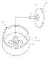
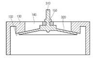
도 1은 종래의 에어 클리너를 도시한 분해 사시도이고, 도 2는 도 1의 에어 클리너에서 드레인 밸브 및 밸브 시트를 하부에서 바라보는 시야로 도시한 분해 사시도이고, 도 3은 도 2의 드레인 밸브가 밸브 시트에 장착된 모습을 도시한 평면도이며, 도 4는 도 3의 A-A선 단면도이다.FIG. 1 is an exploded perspective view showing a conventional air cleaner, FIG. 2 is an exploded perspective view showing a drain valve and a valve seat in the air cleaner of FIG. 1 viewed from below, and FIG. 3 is a cross- FIG. 4 is a cross-sectional view taken along line AA of FIG. 3. FIG.
첨부된 도 1 내지 도 4를 참조하면, 종래의 에어 클리너는, 내부공간을 갖는 하우징(housing)(100) 및 상기 하우징(100)의 내부공간에 수용되는 필터(filter)(미도시)를 포함한다.1 to 4, a conventional air cleaner includes a
상기 하우징(100)은, 상기 필터(미도시)가 삽입 및 탈거 가능하도록 개구부를 갖는 제1 하우징(100A) 및 상기 제1 하우징(100A)의 개구부를 복개하여 상기 내부공간을 형성하는 제2 하우징(100B)을 포함한다.The
상기 제1 하우징(100A)에는, 상기 하우징(100)의 외부로부터 상기 하우징(100)의 내부공간으로 흡기를 안내하는 유입구(110) 및 상기 하우징(100)의 내부공간으로부터 상기 하우징(100)의 외부로 흡기를 안내하는 유출구(120)가 형성된다.The
상기 유입구(110)는 에어 클리너의 흡기 전든 측에 배치되는 에어 덕트(미도시)와 연통되고, 상기 유출구(120)는 에어 클리너의 흡기 후단 측에 배치되는 엔진(미도시)과 연통된다.The inlet 110 communicates with an air duct (not shown) disposed on the side of the air cleaner before the intake air, and the
이러한 구조에 따른 에어 클리너는 엔진(미도시)의 부압에 의해 흡입되는 흡기를 상기 필터(미도시)에 통과시키며 그 흡기에 함유되어 있는 수분, 먼지 등의 이물질을 그 흡기로부터 분리한다.The air cleaner according to this structure passes an intake air sucked by a negative pressure of an engine (not shown) to the filter (not shown), and separates foreign matter such as moisture and dust contained in the intake air from the intake air.
이물질이 제거된 흡기는 상기 엔진(미도시)으로 유입된다.The intake air from which the foreign substance is removed flows into the engine (not shown).
한편, 흡기로부터 분리된 이물질은 상기 하우징(100)의 내부에 쌓이게 되는데, 이러한 이물질이 상기 하우징(100)의 외부로 배출되지 않을 경우에는 다시 흡기와 혼합되어 상기 엔진(미도시)으로 유입되고, 엔진(미도시)의 성능 및 연비 저하와 엔진(미도시)의 고장을 유발할 수 있다.Meanwhile, the foreign matter separated from the intake air is accumulated in the
이를 고려하여, 상기 하우징(100)에는 그 하우징(100)의 내부공간으로부터 외부로 이물질을 배출하기 위한 이물질 배출수단이 구비된다.In consideration of this, the
상기 이물질 배출수단은, 상기 하우징(100)의 외면에 형성되는 밸브 시트(valve seat)(130), 상기 하우징(100)의 내부공간으로부터 상기 하우징(100)의 외부로 이물질을 배출하도록 상기 밸브 시트(130)에 형성되는 드레인 홀(drain hole)(140) 및 상기 드레인 홀(140)을 개폐하는 드레인 밸브(drain valve)(300)를 포함한다.The foreign matter discharging means includes a
상기 드레인 밸브(300)는, 상기 밸브 시트(130)에 형성되는 스템 홀(stem hole)(150)에 삽입 결합되는 밸브 스템(valve stem)(310) 및 상기 드레인 홀(140)을 복개하도록 상기 밸브 스템(310)으로부터 연장되는 밸브 헤드(valve head)(320)를 포함하고, 탄성재질로 형성된다.The
상기 밸브 헤드(320)는, 상기 드레인 밸브(300)의 탄성력과 상기 드레인 홀(140)을 통한 상기 하우징(100)의 내부공간의 압력(엔진의 부압)에 의해 상기 밸브 시트(130)에 접촉되는 방향으로 제1 작용력을 인가 받고, 상기 밸브 헤드(320)에 작용되는 중력(밸브 헤드(320)의 자중, 밸브 헤드(320) 상에 적층된 이물질의 자중)에 의해 상기 밸브 시트(130)로부터 이격되는 방향으로 제2 작용력을 받는다.The
그리고, 상기 밸브 헤드(320)는 상기 제1 작용력과 상기 제2 작용력 사이 관계에 따라 상기 밸브 시트(130)에 접촉 및 이격됨으로써, 상기 드레인 홀(140)을 개폐한다.The valve head 320 contacts and separates from the
구체적으로, 상기 제1 작용력이 상기 제2 작용력보다 큰 경우(예를 들어 엔진(미도시)이 고속 고부하로 운전되어 부압의 크기가 커지거나 상기 하우징(100)의 내부에 쌓인 이물질의 양이 적은 경우), 상기 밸브 헤드(320)가 상기 밸브 시트(130)에 접촉되어 상기 드레인 홀(140)을 폐쇄한다. 이에 따라, 상기 드레인 홀(140)을 통해 상기 하우징(100)의 외부로부터 상기 하우징(100)의 내부로 이물질 및 소음이 유입되는 것을 방지한다.Specifically, when the first acting force is greater than the second acting force (for example, when the engine (not shown) is operated at a high speed and high load to increase the negative pressure or to reduce the amount of foreign matter accumulated in the
반면, 상기 제2 작용력이 상기 제1 작용력보다 큰 경우(예를 들어 엔진(미도시)이 저속 저부하로 운전되어 부압의 크기가 감소되거나 상기 하우징(100)의 내부에 쌓인 이물질의 양이 많은 경우), 상기 밸브 헤드(320)가 상기 밸브 시트(130)로부터 이격되어 상기 드레인 홀(140)을 개방한다. 이에 따라, 상기 드레인 홀(140)을 통해 상기 하우징(100)의 내부로부터 상기 하우징(100)의 외부로 이물질이 배출된다.On the other hand, when the second action force is greater than the first action force (for example, when the engine (not shown) is operated at a low speed low load and the size of the negative pressure is reduced, or the amount of foreign matter accumulated inside the
그러나, 이러한 종래의 에어 클리너에 있어서는, 상기 드레인 밸브(300)가 상기 드레인 홀(140)을 의도와 달리 개폐하는 문제점이 있었다. 구체적으로, 상기 제1 작용력이 상기 제2 작용력보다 커야 할 때(드레인 홀(140)이 폐쇄되어야 할 때), 상기 제1 작용력이 사전에 결정된 크기보다 작아 상기 제2 작용력보다 작아지고, 상기 밸브 헤드(320)가 상기 밸브 시트(130)로부터 이격되고, 상기 드레인 홀(140)이 의도와는 달리 개방되는 문제점이 있었다. 또는, 간헐적인 이상 압력(외력)에 의해 상기 드레인 홀(140)이 의도와 달리 개방되는 문제점이 있었다. 이에 따라, 상기 하우징(100)의 외부로부터 상기 하우징(100)의 내부로 이물질 및 소음이 유입되는 문제점이 있었다.However, in such a conventional air cleaner, there is a problem that the drain valve (300) opens and closes the drain hole (140) unlike the intention. Specifically, when the first acting force is greater than the second acting force (when the
따라서, 본 발명은, 이물질을 배출하기 위한 드레인 홀 및 그 드레인 홀을 개폐하는 드레인 밸브를 포함하고, 상기 드레인 밸브가 상기 드레인 홀을 의도대로 개폐할 수 있는 에어 클리너를 제공하는 것을 그 목적으로 한다.Accordingly, it is an object of the present invention to provide an air cleaner including a drain hole for discharging foreign matter and a drain valve for opening and closing the drain hole, and the drain valve can open / close the drain hole as intended .
본 발명은, 상기한 바와 같은 목적 달성을 위해, 내부공간을 갖고, 그 내부공간에 필터를 수용하는 하우징; 상기 하우징의 외면에 형성되는 밸브 시트; 상기 밸브 시트에 형성되고, 상기 하우징의 내부공간으로부터 상기 하우징의 외부로 이물질을 배출하도록 상기 하우징을 관통하는 드레인 홀; 상기 밸브 시트에 접촉되어 상기 드레인 홀을 폐쇄하고, 상기 밸브 시트로부터 이격되어 상기 드레인 홀을 개방하는 드레인 밸브; 및 상기 밸브 시트에 음각지게 형성되고, 상기 하우징의 내부공간과 연통되는 그루브;를 포함하는 에어 클리너를 제공한다.In order to achieve the above-described object, the present invention provides an air filtering apparatus comprising: a housing having an inner space and accommodating a filter in an inner space thereof; A valve seat formed on an outer surface of the housing; A drain hole formed in the valve seat and passing through the housing to discharge foreign matter from the internal space of the housing to the outside of the housing; A drain valve contacting the valve seat to close the drain hole and to separate the drain hole from the valve seat; And a groove formed in the valve seat so as to engage with the inner space of the housing.
상기 드레인 밸브는, 상기 밸브 시트의 스템 홀에 삽입 결합되는 밸브 스템; 및 상기 드레인 홀을 복개하도록 상기 밸브 스템으로부터 연장되는 밸브 헤드;를 포함하고, 상기 그루브는 상기 밸브 헤드의 범위 내에 형성될 수 있다.Wherein the drain valve includes: a valve stem inserted and coupled to a stem hole of the valve seat; And a valve head extending from the valve stem to cover the drain hole, wherein the groove can be formed within the range of the valve head.
상기 드레인 밸브는 적어도 상기 밸브 헤드가 탄성재질로 형성되고, 상기 밸브 헤드가 상기 밸브 시트에 접촉 및 이격됨으로써, 상기 드레인 홀이 개폐되도록 형성될 수 있다.The drain valve may be formed such that at least the valve head is formed of an elastic material, and the valve head contacts and separates from the valve seat, thereby opening and closing the drain hole.
상기 밸브 헤드는 상기 드레인 홀을 폐쇄할 때 상기 드레인 홀 및 상기 그루브를 통해 상기 하우징의 내부공간의 압력이 인가되도록 형성될 수 있다.The valve head may be configured to apply a pressure of the inner space of the housing through the drain hole and the groove when the drain hole is closed.
상기 드레인 홀은 복수로 형성되고, 복수의 상기 드레인 홀은 상기 스템 홀을 중심으로 방사상으로 배열될 수 있다.The drain holes may be formed in a plurality of, and the plurality of drain holes may be radially arranged around the stem holes.
상기 그루브는, 상기 드레인 홀로부터 상기 스템 홀을 중심으로 하는 원주 방향으로 연장 형성되는 이너 그루브; 상기 드레인 홀로부터 상기 스템 홀의 반대측으로 이격된 위치로부터 상기 스템 홀을 중심으로 하는 원주 방향으로 연장 형성되는 아우터 그루브; 및 상기 이너 그루브로부터 상기 아우터 그루브까지 연장 형성되는 레이디얼 그루브;를 포함할 수 있다.Wherein the groove includes: an inner groove extending from the drain hole in a circumferential direction about the stem hole; An outer groove extending in a circumferential direction around the stem hole from a position spaced apart from the drain hole on the opposite side of the stem hole; And a radial groove extending from the inner groove to the outer groove.
상기 이너 그루브는 상기 드레인 홀을 통해 상기 하우징의 내부공간과 연통되고, 상기 레이디얼 그루브는 상기 이너 그루브와 연통되고, 상기 아우터 그루브는 상기 레이디얼 그루브와 연통될 수 있다.The inner groove communicates with the inner space of the housing through the drain hole. The radial groove communicates with the inner groove, and the outer groove communicates with the radial groove.
상기 아우터 그루브는 상기 밸브 헤드의 외주면과 복수의 상기 드레인 홀 사이 영역에서 복수의 상기 드레인 홀을 에워싸는 하나의 환형으로 형성될 수 있다.The outer groove may be formed in an annular shape surrounding a plurality of drain holes in an area between an outer circumferential surface of the valve head and a plurality of the drain holes.
상기 이너 그루브는 복수의 상기 드레인 홀 사이마다 형성될 수 있다.The inner grooves may be formed between the plurality of drain holes.
상기 레이디얼 그루브는 복수의 상기 드레인 홀 사이마다 형성될 수 있다.The radial groove may be formed between the plurality of drain holes.
본 발명에 의한 에어 클리너는, 하우징, 상기 하우징의 외면에 형성되는 밸브 시트, 이물질을 배출하도록 상기 밸브 시트에 형성되는 드레인 홀, 상기 드레인 홀을 개폐하는 드레인 밸브 및 상기 밸브 시트에 음각지게 형성되고 상기 하우징의 내부공간과 연통되는 그루브를 포함함으로써, 상기 드레인 밸브와 상기 밸브 시트 사이 접촉력이 향상될 수 있다. 이에 의하여, 상기 드레인 밸브가 상기 드레인 홀을 의도대로 개폐할 수 있다. 이에 따라, 상기 하우징의 외부로부터 상기 하우징의 내부로 이물질 및 소음이 유입되는 것을 방지할 수 있다.The air cleaner according to the present invention comprises a housing, a valve seat formed on an outer surface of the housing, a drain hole formed in the valve seat to discharge foreign substances, a drain valve opening and closing the drain hole, By including the groove communicating with the inner space of the housing, the contact force between the drain valve and the valve seat can be improved. Thereby, the drain valve can open / close the drain hole as intended. Accordingly, foreign matter and noise can be prevented from flowing into the housing from the outside of the housing.
도 1은 종래의 에어 클리너를 도시한 분해 사시도,
도 2는 도 1의 에어 클리너에서 드레인 밸브 및 밸브 시트를 도시한 분해 사시도,
도 3은 도 2의 드레인 밸브가 밸브 시트에 장착된 모습을 도시한 평면도,
도 4는 도 3의 A-A선 단면도,
도 5는 본 발명의 일 실시예에 따른 에어 클리너에서 드레인 밸브 및 밸브 시트를 도시한 분해 사시도,
도 6은 도 5의 드레인 밸브가 밸브 시트에 장착된 모습을 도시한 평면도,
도 7은 도 6의 B-B선 단면도,
도 8은 도 6의 C-C선 단면도,
도 9는 도 7의 드레인 밸브가 드레인 홀을 개방한 모습을 도시한 단면도이다.1 is an exploded perspective view showing a conventional air cleaner,
Fig. 2 is an exploded perspective view showing the drain valve and the valve seat in the air cleaner of Fig. 1,
FIG. 3 is a plan view showing a state in which the drain valve of FIG. 2 is mounted on a valve seat,
4 is a sectional view taken along line AA in Fig. 3,
5 is an exploded perspective view showing a drain valve and a valve seat in an air cleaner according to an embodiment of the present invention,
FIG. 6 is a plan view showing a state in which the drain valve of FIG. 5 is mounted on the valve seat,
Fig. 7 is a sectional view taken along line BB of Fig. 6,
8 is a sectional view taken along the line CC of Fig. 6,
9 is a sectional view showing a state in which the drain valve of FIG. 7 opens the drain hole.
이하, 본 발명에 의한 에어 클리너를 첨부된 도면을 참조하여 상세히 설명한다.Hereinafter, an air cleaner according to the present invention will be described in detail with reference to the accompanying drawings.
도 5는 본 발명의 일 실시예에 따른 에어 클리너에서 드레인 밸브 및 밸브 시트를 하부에서 바라보는 시야로 도시한 분해 사시도이고, 도 6은 도 5의 드레인 밸브가 밸브 시트에 장착된 모습을 도시한 평면도이고, 도 7은 도 6의 B-B선 단면도이고, 도 8은 도 6의 C-C선 단면도이며, 도 9는 도 7의 드레인 밸브가 드레인 홀을 개방한 모습을 도시한 단면도이다.FIG. 5 is an exploded perspective view showing a drain valve and a valve seat in a view from below in an air cleaner according to an embodiment of the present invention, and FIG. 6 shows a state in which the drain valve of FIG. 5 is mounted on a valve seat 6 is a cross-sectional view taken along the line BB in Fig. 6, Fig. 8 is a cross-sectional view taken along the line CC in Fig. 6, and Fig. 9 is a sectional view showing a state in which the drain valve of Fig.
첨부된 도 5 내지 도 9를 참조하면, 본 발명의 일 실시예에 따른 에어 클리너는, 내부공간을 갖는 하우징(100) 및 상기 하우징(100)의 내부공간에 수용되는 필터(미도시)를 포함할 수 있다.5 to 9, an air cleaner according to an embodiment of the present invention includes a
상기 하우징(100)은, 상기 필터(미도시)가 삽입 및 탈거 가능하도록 개구부를 갖는 제1 하우징(100A) 및 상기 제1 하우징(100A)의 개구부를 복개하여 상기 내부공간을 형성하는 제2 하우징(100B)을 포함할 수 있다.The
상기 제1 하우징(100A)에는, 상기 하우징(100)의 외부로부터 상기 하우징(100)의 내부공간으로 흡기를 안내하는 유입구(110) 및 상기 하우징(100)의 내부공간으로부터 상기 하우징(100)의 외부로 흡기를 안내하는 유출구(120)가 형성될 수 있다.The
상기 유입구(110)는 에어 클리너의 흡기 전단 측에 배치되는 에어 덕트(미도시)와 연통될 수 있다.The inlet 110 may communicate with an air duct (not shown) disposed on the intake front end side of the air cleaner.
상기 유출구(120)는 에어 클리너의 흡기 후단 측에 배치되는 엔진(미도시)과 연통될 수 있다.The
한편, 본 실시예에 따른 에어 클리너는, 상기 하우징(100)의 내부공간으로부터 상기 하우징(100)의 외부로 이물질을 배출하기 위한 이물질 배출수단을 포함할 수 있다.Meanwhile, the air cleaner according to the present embodiment may include foreign matter discharging means for discharging foreign matter from the internal space of the
상기 이물질 배출수단은, 상기 하우징(100)의 외면에 형성되는 밸브 시트(130), 상기 하우징(100)의 내부공간으로부터 상기 하우징(100)의 외부로 이물질을 배출하도록 상기 밸브 시트(130)에 형성되는 드레인 홀(140), 상기 드레인 홀(140)을 개폐하는 드레인 밸브(300) 및 상기 드레인 밸브(300)와 상기 밸브 시트(130) 사이 접촉력을 향상시키는 그루브(groove)(160)를 포함할 수 있다.The foreign matter discharging means includes a
상기 밸브 시트(130)는 대략 원판형으로 형성되고, 상기 드레인 밸브(300)의 후술할 밸브 헤드(320)와 접촉 가능한 밸브 시트 면(132)(하우징(100)의 외부에 대향되는 면)이 깔때기 형상으로 형성될 수 있다. 즉, 상기 밸브 시트 면(132)은 상기 밸브 시트(130)의 외주부로부터 상기 밸브 시트(130)의 중심부로 갈수록 상기 하우징(100)의 내부공간 측으로 우묵하게 형성될 수 있다.The
한편, 상기 밸브 시트(130)의 중심부에는 상기 드레인 밸브(300)의 후술할 밸브 스템(310)이 삽입되는 스템 홀(150)이 형성될 수 있다.A
상기 스템 홀(150)은 상기 밸브 시트(130)의 중심부에서 상기 하우징(100)을 관통하여 형성될 수 있다.The
상기 드레인 홀(140)은 상기 밸브 시트 면(132)으로부터 음각지게 형성되고, 상기 하우징(100)을 관통하여 형성될 수 있다.The
그리고, 상기 드레인 홀(140)은 복수로 형성될 수 있다.The
복수의 상기 드레인 홀(140)은 상기 스템 홀(150)을 중심으로 방사상으로 배열되게 형성될 수 있다. 즉, 복수의 상기 드레인 홀(140)은 상기 스템 홀(150)을 중심으로 하는 원주 방향을 따라 서로 이격되게 배열될 수 있다. 여기서, 복수의 상기 드레인 홀(140)은 상기 스템 홀(150)을 중심으로 하는 원주 방향을 따라 등간격으로 배열되는 것이 바람직할 수 있다.The plurality of drain holes 140 may be radially arranged around the stem holes 150. That is, the plurality of drain holes 140 may be spaced apart from each other along the circumferential direction about the
상기 드레인 밸브(300)는, 상기 스템 홀(150)에 삽입 결합되는 밸브 스템(310) 및 상기 드레인 홀(140)을 복개하도록 상기 밸브 스템(310)으로부터 연장되는 밸브 헤드(320)를 포함할 수 있다.The
상기 밸브 스템(310)은 일 방향으로 연장된 원기둥형으로 형성되고, 상기 스템 홀(150)에 삽입될 때 예를 들어 걸림 체결과 같은 방식으로 그 스템 홀(150)에 고정되도록 형성될 수 있다.The valve stem 310 may be formed in a cylindrical shape extending in one direction and may be formed to be fixed to the
상기 밸브 헤드(320)는 상기 밸브 스템(310)의 일단부로부터 방사상으로 연장되는 원판형(더욱 정확히는, 깔때기형)으로 형성될 수 있다.The
그리고, 상기 밸브 헤드(320)는 복수의 상기 드레인 홀(140)을 모두 수용하되, 상기 밸브 헤드(320)의 외주면이 복수의 상기 드레인 홀(140)을 기준으로 상기 스템 홀(150)의 반대측으로 그 복수의 드레인 홀(140)에 이격되도록 형성될 수 있다. 즉, 상기 밸브 헤드(320)의 외경이 복수의 상기 드레인 홀(140)의 공통 외접선의 외경보다 크게 형성될 수 있다.The
여기서, 상기 드레인 밸브(300)는, 상기 밸브 헤드(320)가 상기 밸브 시트 면(132)에 접촉되어 복수의 상기 드레인 홀(140)을 폐쇄하거나, 상기 밸브 헤드(320)가 상기 밸브 시트 면(132)으로부터 이격되어 복수의 상기 드레인 홀(140)을 개방하도록, 적어도 상기 밸브 헤드(320)가 탄성 재질로 형성될 수 있다. 본 실시예의 경우, 상기 드레인 밸브(300)는, 상기 밸브 스템(310)이 상기 밸브 헤드(320)가 상기 밸브 시트 면(132)에 접촉되는 방향으로 상기 밸브 헤드(320)에 예압을 인가하기 위해, 상기 밸브 헤드(320)뿐만 아니라 상기 밸브 스템(310)도 탄성 재질로 형성될 수 있다.Here, the
상기 그루브(160)는 상기 밸브 시트 면(132) 중 상기 밸브 헤드(320)의 범위 내에서 그 밸브 시트 면(132)에 음각지게 형성되고, 상기 드레인 홀(140)에 연통됨으로써 상기 하우징(100)의 내부공간과 연통되게 형성될 수 있다.The
구체적으로, 상기 그루브(160)는, 상기 드레인 홀(140)로부터 상기 스템 홀(150)을 중심으로 하는 원주 방향으로 연장 형성되는 이너 그루브(inner groove)(162), 상기 드레인 홀(140)로부터 상기 스템 홀(150)의 반대측으로 이격된 위치로부터 상기 스템 홀(150)을 중심으로 하는 원주 방향으로 연장 형성되는 아우터 그루브(outer groove)(166) 및 상기 이너 그루브(162)로부터 상기 아우터 그루브(166)까지 연장 형성되는 레이디얼 그루브(radial groove)(164)를 포함할 수 있다.Specifically, the
상기 이너 그루브(162)는 복수의 상기 드레인 홀(140) 사이마다 형성될 수 있다. 즉, 복수의 상기 드레인 홀(140) 중 임의의 드레인 홀을 제a 드레인 홀이라 하고, 상기 제a 드레인 홀을 기준으로 일측에서 그 제a 드레인 홀에 인접한 드레인 홀을 제a-1 드레인 홀이라 하며, 상기 제a 드레인 홀을 기준으로 상기 제a-1 드레인 홀의 반대측에서 그 제a 드레인 홀에 인접한 드레인 홀을 제a+1 드레인 홀이라 할 때, 상기 이너 그루브(162)는, 상기 제a 드레인 홀로부터 상기 제a-1 드레인 홀까지 연장되는 제b 이너 그루브 및 상기 제a 드레인 홀로부터 상기 제a+1 드레인 홀까지 연장되는 제b+1 이너 그루브를 포함할 수 있다.The
여기서, 상기 이너 그루브(162)는 복수의 상기 드레인 홀(140) 사이들 중 일부에만 형성될 수도 있으나, 후술할 바와 같이 상기 밸브 헤드(320)에 상기 그루브(160)를 통해 상기 하우징(100)의 내부공간의 압력(부압)이 인가될 때 그 압력이 상기 밸브 헤드(320) 전반에 걸쳐 균일하게 인가되어 상기 밸브 헤드(320)와 상기 밸브 시트 면(132) 사이 접촉력을 향상시키도록, 복수의 상기 드레인 홀(140) 사이마다 형성되는 것이 바람직할 수 있다.The
상기 아우터 그루브(166)는 상기 밸브 헤드(320)의 외주면과 복수의 상기 드레인 홀(140) 사이 영역에서 복수의 상기 드레인 홀(140)을 에워싸는 하나의 환형으로 형성될 수 있다. 즉, 상기 아우터 그루브(166)는 상기 스템 홀(150)을 중심으로 하는 원주 방향을 따라 연속되게 형성되고, 내주부에 복수의 상기 드레인 홀(140)을 수용할 수 있다.The
상기 레이디얼 그루브(164)는 복수의 상기 드레인 홀(140) 사이마다 형성될 수 있다. 즉, 상기 레이디얼 그루브(164)는, 상기 제a 드레인 홀과 상기 제a-1 드레인 홀 사이에서 상기 제b 이너 그루브로부터 상기 아우터 그루브(166)까지 연장되는 제c 레이디얼 그루브 및 상기 제a 드레인 홀과 상기 제a+1 드레인 사이에서 상기 제b+1 이너 그루브로부터 상기 아우터 그루브(166) 까지 연장되는 제c+1 레이디얼 그루브를 포함할 수 있다.The
여기서, 상기 레이디얼 그루브(164)는 복수의 상기 드레인 홀(140) 사이들 중 일부에만 형성될 수도 있으나, 후술할 바와 같이 상기 밸브 헤드(320)에 상기 그루브(160)를 통해 상기 하우징(100)의 내부공간의 압력(부압)이 인가될 때 그 압력이 상기 밸브 헤드(320) 전반에 걸쳐 균일하게 인가되어 상기 밸브 헤드(320)와 상기 밸브 시트 면(132) 사이 접촉력을 향상시키도록, 복수의 상기 드레인 홀(140) 사이마다 형성되는 것이 바람직할 수 있다.Here, the
이러한 구성에 따른 상기 그루브(160)는, 상기 이너 그루브(162)가 상기 드레인 홀(140)에 연통되어 상기 드레인 홀(140)을 통해 상기 하우징(100)의 내부공간과 연통되고, 상기 레이디얼 그루브(164)가 상기 이너 그루브(162)에 연통되어 상기 이너 그루브(162) 및 상기 드레인 홀(140)을 통해 상기 하우징(100)의 내부공간과 연통되며, 상기 아우터 그루브(166)가 상기 레이디얼 그루브(164)에 연통되어 상기 레이디얼 그루브(164), 상기 이너 그루브(162) 및 상기 드레인 홀(140)을 통해 상기 하우징(100)의 내부공간과 연통됨으로써, 상기 하우징(100)의 내부공간과 연통될 수 있다.The
이하, 본 실시예에 따른 에어 클리너의 작용효과에 대해 설명한다.Hereinafter, the operation and effect of the air cleaner according to the present embodiment will be described.
즉, 본 실시예에 따른 에어 클리너는 엔진(미도시)의 부압에 의해 흡입되는 흡기를 상기 필터(미도시)에 통과시키며 그 흡기에 함유되어 있는 수분, 먼지 등의 이물질을 그 흡기로부터 분리할 수 있다.That is, the air cleaner according to the present embodiment allows an intake air sucked by the negative pressure of an engine (not shown) to pass through the filter (not shown) and to separate foreign matter such as moisture, dust, etc. contained in the intake air from the intake air .
이물질이 제거된 흡기는 상기 엔진(미도시)으로 유입될 수 있다.The intake air from which the foreign substance is removed can be introduced into the engine (not shown).
한편, 흡기로부터 분리된 이물질은 상기 하우징(100)의 내부공간으로부터 상기 하우징(100)의 외부로 배출될 수 있다.Meanwhile, the foreign matter separated from the intake air can be discharged from the inner space of the
구체적으로, 흡기로부터 분리된 이물질은 상기 하우징(100)의 내벽면을 타고 상기 밸브 시트(130) 측으로 유동될 수 있다.Specifically, the foreign matter separated from the intake air can flow toward the
상기 밸브 시트(130) 측으로 유동된 이물질은 상기 드레인 홀(140)이 상기 드레인 밸브(300)에 의해 폐쇄될 경우 상기 드레인 밸브(300)에 저지되어 상기 하우징(100)의 내부공간에 쌓이고, 상기 드레인 홀(140)이 상기 드레인 밸브(300)에 의해 개방될 경우 상기 드레인 홀(140)과 상기 드레인 밸브(300) 사이 유격을 통해 상기 하우징(100)의 외부로 배출될 수 있다.A foreign matter flowing toward the
여기서, 상기 드레인 홀(140)은 다음과 같은 원리로 개폐될 수 있다.Here, the
즉, 상기 밸브 헤드(320)는, 상기 드레인 밸브(300)의 탄성력과 상기 하우징(100)의 내부공간의 압력(부압)에 의해 상기 밸브 시트(130)에 접촉되는 방향으로 제1 작용력을 인가받고, 상기 밸브 헤드(320)에 작용되는 중력(밸브 헤드(320)의 자중, 밸브 헤드(320) 상에 적층된 이물질의 자중에 의해 밸브 헤드(320)에 가해지는 힘)에 의해 상기 밸브 시트(130)로부터 이격되는 방향으로 제2 작용력을 인가받을 수 있다.That is, the
그리고, 상기 밸브 헤드(320)는 상기 제1 작용력과 상기 제2 작용력 사이 관계에 따라 상기 밸브 시트(130)에 접촉 및 이격됨으로써, 상기 드레인 홀(140)을 개폐할 수 있다.The
구체적으로, 상기 제1 작용력이 상기 제2 작용력보다 큰 경우(예를 들어, 엔진(미도시)이 고속 고부하로 운전되어 부압의 크기가 커지거나 상기 하우징(100)의 내부에 쌓인 이물질의 양이 적은 경우), 상기 밸브 헤드(320)가 상기 밸브 시트(130)에 접촉되어 상기 드레인 홀(140)을 폐쇄할 수 있다. 이에 따라, 상기 드레인 홀(140)을 통해 상기 하우징(100)의 외부로부터 상기 하우징(100)의 내부로 이물질 및 소음이 유입되는 것을 방지할 수 있다.Specifically, when the first acting force is greater than the second acting force (for example, when the engine (not shown) is operated at a high speed and high load, the negative pressure increases in size or the amount of foreign matter accumulated in the
반면, 상기 제2 작용력이 상기 제1 작용력보다 큰 경우(예를 들어 엔진(미도시)이 저속 저부하로 운전되어 부압의 크기가 감소되거나 상기 하우징(100)의 내부에 쌓인 이물질의 양이 많은 경우), 상기 밸브 헤드(320)가 상기 밸브 시트(130)로부터 이격되어 상기 드레인 홀(140)을 개방할 수 있다. 이에 따라, 상기 드레인 홀(140)을 통해 상기 하우징(100)의 내부로부터 상기 하우징(100)의 외부로 이물질이 배출될 수 있다. 이에 의하여, 이물질이 다시 흡기와 혼합되어 상기 엔진(미도시)으로 유입되는 것이 방지되고, 이로 인해 엔진(미도시)의 성능 및 연비 저하와 엔진(미도시)의 고장이 발생되는 것을 방지할 수 있다.On the other hand, when the second action force is greater than the first action force (for example, when the engine (not shown) is operated at a low speed low load and the size of the negative pressure is reduced, or the amount of foreign matter accumulated inside the
여기서, 본 실시예에 따른 에어 클리너는 상기 그루브(160)를 포함함으로써, 상기 드레인 밸브(300)가 상기 드레인 홀(140)을 의도대로 개폐할 수 있다.Here, the air cleaner according to the present embodiment includes the
구체적으로, 상기 제1 작용력이 상기 제2 작용력보다 커야 할 때(드레인 홀(140)이 폐쇄되어야 할 때), 간헐적인 이상 압력(외력)이 작용할 경우나 상기 제1 작용력이 사전에 결정된 크기보다 작아 상기 제2 작용력보다 작을 경우, 상기 밸브 헤드(320)가 상기 밸브 시트(130)로부터 이격되고, 상기 드레인 홀(140)이 의도와는 달리 개방되며, 이에 따라 상기 하우징(100)의 외부로부터 상기 하우징(100)의 내부로 이물질 및 소음이 유입되는 문제점이 발생될 수 있다.Specifically, when the first acting force is greater than the second acting force (when the
하지만, 본 실시예의 경우, 상기 밸브 시트 면(132)에 상기 그루브(160)가 형성됨에 따라, 상기 밸브 헤드(320)는 상기 드레인 홀(140)을 폐쇄할 때 상기 드레인 홀(140)을 통해 상기 하우징(100)의 내부공간의 압력(부압)을 인가받을 뿐만 아니라, 상기 그루브(160)를 통해서도 상기 하우징(100)의 내부공간의 압력(부압)을 인가받을 수 있다. 이에 의하여, 상기 제1 작용력이 사전에 결정된 크기보다 크거나 같아질 수 있다. 즉, 상기 드레인 밸브(300)와 상기 밸브 시트(130) 사이 접촉력이 향상될 수 있다. 이에 따라, 상기 제1 작용력이 상기 제2 작용력보다 커야 할 때(드레인 홀(140)이 폐쇄되어야 할 때), 상기 제1 작용력이 상기 제2 작용력보다 커져, 상기 밸브 헤드(320)가 상기 밸브 시트(130)에 접촉되고, 상기 드레인 홀(140)이 의도대로 폐쇄되며, 이에 따라 상기 하우징(100)의 외부로부터 상기 하우징(100)의 내부로 이물질 및 소음이 유입되는 것이 방지될 수 있다. 그리고, 간헐적인 이상 압력(외력)이 작용되더라도 상기 드레인 홀(140)이 의도대로 폐쇄되어, 이물질의 유입이 차단될 수 있다. 그리고, 이물질이 흡기와 혼합되어 상기 엔진(미도시)으로 유입되는 것이 방지되고, 이로 인해 엔진(미도시)의 성능 및 연비 저하와 엔진(미도시)의 고장이 발생되는 것을 방지할 수 있다.However, according to the present embodiment, as the
한편, 상기 그루브(160)가 상기 이너 그루브(162), 상기 레이디얼 그루브(164) 및 상기 아우터 그루브(166)를 구비하여 구성됨에 따라, 상기 드레인 밸브(300)와 상기 밸브 시트(130) 사이 접촉력이 더욱 향상될 수 있다.Since the
그리고, 상기 드레인 홀(140)이 복수로 구비되고, 복수의 상기 드레인 홀(140)이 원주 방향으로 등간격으로 배열되며, 상기 이너 그루브(162)가 복수의 상기 드레인 홀(140) 사이마다 형성됨에 따라, 상기 밸브 헤드(320)의 전반에 걸쳐 상기 하우징(100)의 내부공간의 압력(부압)이 균일하게 인가되고, 상기 드레인 밸브(300)와 상기 밸브 시트(130) 사이 접촉력이 더욱 더 향상될 수 있다.The plurality of drain holes 140 are arranged at regular intervals in the circumferential direction and the
그리고, 상기 레이디얼 그루브(164)도 복수의 상기 드레인 홀(140) 사이마다 형성됨에 따라, 상기 밸브 헤드(320)의 전반에 걸쳐 상기 하우징(100)의 내부공간의 압력(부압)이 더욱 균일하게 인가되고, 상기 드레인 밸브(300)와 상기 밸브 시트(130) 사이 접촉력이 훨씬 향상될 수 있다.Since the
그리고, 상기 아우터 그루브(166)가 복수의 상기 드레인 홀(140)을 감싸도록 형성됨에 따라, 상기 밸브 헤드(320)의 전반에 걸쳐 상기 하우징(100)의 내부공간의 압력(부압)이 더욱 더 균일하게 인가되고, 상기 드레인 밸브(300)와 상기 밸브 시트(130) 사이 접촉력이 훨씬 더 향상될 수 있다.Since the
한편, 이물질이 상기 하우징(100)의 내부공간에 쌓일 경우, 그 이물질이 상기 그루브(160)의 적어도 일 부분에 유입될 수 있다. 이 경우, 상기 그루브(160) 중 부압이 작용되는 부위가 점진적으로 감소되고, 이에 따라 상기 제1 작용력이 점진적으로 감소되어, 이물질의 외부 배출이 용이해 질 수 있다. 즉, 상기 그루브(160)에 의해 자칫 이물질이 의도와 달리 배출되지 못하는 문제점이 방지될 수 있다.If the foreign matter is accumulated in the internal space of the
100: 하우징130: 밸브 시트
140: 드레인 홀150: 스템 홀
160: 그루브162: 이너 그루브
164: 레이디얼 그루브166: 아우터 그루브
300: 드레인 밸브310: 밸브 스템
320: 밸브 헤드100: housing 130: valve seat
140: Drain hole 150: Stem hole
160: groove 162: inner groove
164: Radial groove 166: Outer groove
300: drain valve 310: valve stem
320: valve head
Claims (10)
Translated fromKorean상기 하우징(100)의 외면에 형성되는 밸브 시트(130);
상기 밸브 시트(130)에 형성되고, 상기 하우징(100)의 내부공간으로부터 상기 하우징(100)의 외부로 이물질을 배출하도록 상기 하우징(100)을 관통하는 드레인 홀(140);
상기 밸브 시트(130)에 접촉되어 상기 드레인 홀(140)을 폐쇄하고, 상기 밸브 시트(130)로부터 이격되어 상기 드레인 홀(140)을 개방하는 드레인 밸브(300); 및
상기 밸브 시트(130)에 음각지게 형성되고, 상기 하우징(100)의 내부공간과 연통되는 그루브(160);를 포함하며,
상기 드레인 홀(140)은 복수로 형성되고,
복수의 상기 드레인 홀(140)은 스템 홀(150)을 중심으로 방사상으로 배열되고,
상기 그루브(160)는,
상기 드레인 홀(140)로부터 상기 스템 홀(150)을 중심으로 하는 원주 방향으로 연장 형성되는 이너 그루브(162);
상기 드레인 홀(140)로부터 상기 스템 홀(150)의 반대측으로 이격된 위치로부터 상기 스템 홀(150)을 중심으로 하는 원주 방향으로 연장 형성되는 아우터 그루브(166); 및
상기 이너 그루브(162)로부터 상기 아우터 그루브(166)까지 연장 형성되는 레이디얼 그루브(164);를 포함하는,
에어 클리너.A housing (100) having an inner space and accommodating the filter in its inner space;
A valve seat 130 formed on the outer surface of the housing 100;
A drain hole 140 formed in the valve seat 130 and passing through the housing 100 to discharge foreign substances from the internal space of the housing 100 to the outside of the housing 100;
A drain valve 300 contacting the valve seat 130 to close the drain hole 140 and to open the drain hole 140 away from the valve seat 130; And
And a groove (160) formed on the valve seat (130) to communicate with an inner space of the housing (100)
The drain holes 140 are formed in a plurality of layers,
The plurality of drain holes 140 are radially arranged around the stem holes 150,
The groove (160)
An inner groove (162) extending from the drain hole (140) in the circumferential direction about the stem hole (150);
An outer groove 166 extending in a circumferential direction around the stem hole 150 from a position spaced apart from the drain hole 140 on the opposite side of the stem hole 150; And
And a radial groove (164) extending from the inner groove (162) to the outer groove (166).
Air cleaner.
상기 드레인 밸브(300)는,
상기 밸브 시트(130)의 스템 홀(150)에 삽입 결합되는 밸브 스템(310); 및
상기 드레인 홀(140)을 복개하도록 상기 밸브 스템(310)으로부터 연장되는 밸브 헤드(320);를 포함하고,
상기 그루브(160)는 상기 밸브 헤드(320)의 범위 내에 형성되는 에어 클리너.The method according to claim 1,
The drain valve (300)
A valve stem 310 inserted into the stem hole 150 of the valve seat 130; And
And a valve head (320) extending from the valve stem (310) to cover the drain hole (140)
Wherein the groove (160) is formed within a range of the valve head (320).
상기 드레인 밸브(300)는 적어도 상기 밸브 헤드(320)가 탄성재질로 형성되고,
상기 밸브 헤드(320)가 상기 밸브 시트(130)에 접촉 및 이격됨으로써, 상기 드레인 홀(140)이 개폐되는 에어 클리너.3. The method of claim 2,
In the drain valve 300, at least the valve head 320 is formed of an elastic material,
And the drain hole (140) is opened or closed by contacting and separating the valve head (320) with the valve seat (130).
상기 밸브 헤드(320)는 상기 드레인 홀(140)을 폐쇄할 때 상기 드레인 홀(140) 및 상기 그루브(160)를 통해 상기 하우징(100)의 내부공간의 압력이 인가되는 것을 특징으로 하는 에어 클리너.The method of claim 3,
Wherein the valve head is applied with a pressure in an inner space of the housing through the drain hole and the groove when the drain hole is closed. .
상기 이너 그루브(162)는 상기 드레인 홀(140)을 통해 상기 하우징(100)의 내부공간과 연통되고,
상기 레이디얼 그루브(164)는 상기 이너 그루브(162)와 연통되고,
상기 아우터 그루브(166)는 상기 레이디얼 그루브(164)와 연통되는 것을 특징으로 하는 에어 클리너.The method according to claim 1,
The inner groove 162 communicates with the inner space of the housing 100 through the drain hole 140,
The radial groove 164 communicates with the inner groove 162,
Wherein the outer groove (166) communicates with the radial groove (164).
상기 아우터 그루브(166)는 밸브 헤드(320)의 외주면과 복수의 상기 드레인 홀(140) 사이 영역에서 복수의 상기 드레인 홀(140)을 에워싸는 하나의 환형으로 형성되는 에어 클리너.The method according to claim 1,
Wherein the outer groove (166) is formed in one annular shape surrounding a plurality of the drain holes (140) in a region between an outer peripheral surface of the valve head (320) and a plurality of the drain holes (140).
상기 이너 그루브(162)는 복수의 상기 드레인 홀(140) 사이마다 형성되는 에어 클리너.9. The method of claim 8,
Wherein the inner grooves (162) are formed between the plurality of drain holes (140).
상기 레이디얼 그루브(164)는 복수의 상기 드레인 홀(140) 사이마다 형성되는 에어 클리너.10. The method of claim 9,
Wherein the radial groove (164) is formed between the plurality of drain holes (140).
Priority Applications (1)
| Application Number | Priority Date | Filing Date | Title |
|---|---|---|---|
| KR1020160173638AKR101956350B1 (en) | 2016-12-19 | 2016-12-19 | Air cleaner |
Applications Claiming Priority (1)
| Application Number | Priority Date | Filing Date | Title |
|---|---|---|---|
| KR1020160173638AKR101956350B1 (en) | 2016-12-19 | 2016-12-19 | Air cleaner |
Publications (2)
| Publication Number | Publication Date |
|---|---|
| KR20180070986A KR20180070986A (en) | 2018-06-27 |
| KR101956350B1true KR101956350B1 (en) | 2019-03-08 |
Family
ID=62789640
Family Applications (1)
| Application Number | Title | Priority Date | Filing Date |
|---|---|---|---|
| KR1020160173638AExpired - Fee RelatedKR101956350B1 (en) | 2016-12-19 | 2016-12-19 | Air cleaner |
Country Status (1)
| Country | Link |
|---|---|
| KR (1) | KR101956350B1 (en) |
Families Citing this family (1)
| Publication number | Priority date | Publication date | Assignee | Title |
|---|---|---|---|---|
| DE102020108055A1 (en)* | 2020-03-24 | 2021-09-30 | Mann+Hummel Gmbh | Particle discharge device, filter assembly and method |
Citations (2)
| Publication number | Priority date | Publication date | Assignee | Title |
|---|---|---|---|---|
| KR200147140Y1 (en)* | 1996-12-05 | 1999-06-15 | 정몽규 | Foreign body drain structure of air cleaner |
| JP2016008683A (en) | 2014-06-25 | 2016-01-18 | 浜名湖電装株式会社 | Fluid control valve device |
Family Cites Families (4)
| Publication number | Priority date | Publication date | Assignee | Title |
|---|---|---|---|---|
| US4388091A (en)* | 1981-07-29 | 1983-06-14 | Nelson Industries, Inc. | Air cleaner having a dust dumping valve |
| KR20040095372A (en)* | 2003-04-28 | 2004-11-15 | 기아자동차주식회사 | Unloader valve in air cleaner |
| KR20050047417A (en) | 2003-11-17 | 2005-05-20 | 기아자동차주식회사 | Water drain device of air cleaner |
| KR20060089051A (en)* | 2005-02-03 | 2006-08-08 | 기아자동차주식회사 | Drain Valve for Car Air Cleaner |
- 2016
- 2016-12-19KRKR1020160173638Apatent/KR101956350B1/ennot_activeExpired - Fee Related
Patent Citations (2)
| Publication number | Priority date | Publication date | Assignee | Title |
|---|---|---|---|---|
| KR200147140Y1 (en)* | 1996-12-05 | 1999-06-15 | 정몽규 | Foreign body drain structure of air cleaner |
| JP2016008683A (en) | 2014-06-25 | 2016-01-18 | 浜名湖電装株式会社 | Fluid control valve device |
Also Published As
| Publication number | Publication date |
|---|---|
| KR20180070986A (en) | 2018-06-27 |
Similar Documents
| Publication | Publication Date | Title |
|---|---|---|
| CN106838401B (en) | Valve device | |
| JP4928707B2 (en) | Device for deoiling from crankcase ventilation gas of internal combustion engine | |
| US9403107B2 (en) | Liquid filter having a filter bypass valve and filter insert therefor | |
| US6792925B2 (en) | Filter device | |
| CN104603462A (en) | Poppet valve for a compressor | |
| US10774835B2 (en) | Vacuum pump with sound absorption and check valve | |
| KR101956350B1 (en) | Air cleaner | |
| US9416695B2 (en) | Non-return valve for an oil return in the crankcase ventilation system of a combustion engine | |
| KR102001780B1 (en) | Open Type Air Breather | |
| US20200300135A1 (en) | Oil separator | |
| JP7161918B2 (en) | vacuum pump | |
| JP7152295B2 (en) | vacuum pump | |
| KR101416365B1 (en) | Assist intake valve and intake system provided with the same | |
| CN101842615B (en) | ventilation device | |
| JP2007198279A (en) | Composite valve, and blowby gas reducing device of engine equipped with composite valve | |
| KR101251711B1 (en) | Closed crankcase ventilation comprising device for preventing oil backdraft | |
| JP2005520971A (en) | Valve for fluid filter | |
| CN111140502A (en) | Vacuum pump | |
| JP2009115100A (en) | Scroll compressor | |
| US20140251466A1 (en) | Pneumatic port shield | |
| US10247068B2 (en) | Oil separating module in the crankcase ventilation system of a combustion engine | |
| CN218509566U (en) | Engine safety valve subassembly | |
| KR101929262B1 (en) | Air pressure adjustment pilot valve assembly | |
| JP7230725B2 (en) | non-return valve | |
| JP2017082664A (en) | Air cleaner |
Legal Events
| Date | Code | Title | Description |
|---|---|---|---|
| A201 | Request for examination | ||
| PA0109 | Patent application | St.27 status event code:A-0-1-A10-A12-nap-PA0109 | |
| PA0201 | Request for examination | St.27 status event code:A-1-2-D10-D11-exm-PA0201 | |
| P11-X000 | Amendment of application requested | St.27 status event code:A-2-2-P10-P11-nap-X000 | |
| P13-X000 | Application amended | St.27 status event code:A-2-2-P10-P13-nap-X000 | |
| D13-X000 | Search requested | St.27 status event code:A-1-2-D10-D13-srh-X000 | |
| D14-X000 | Search report completed | St.27 status event code:A-1-2-D10-D14-srh-X000 | |
| E902 | Notification of reason for refusal | ||
| PE0902 | Notice of grounds for rejection | St.27 status event code:A-1-2-D10-D21-exm-PE0902 | |
| E13-X000 | Pre-grant limitation requested | St.27 status event code:A-2-3-E10-E13-lim-X000 | |
| P11-X000 | Amendment of application requested | St.27 status event code:A-2-2-P10-P11-nap-X000 | |
| P13-X000 | Application amended | St.27 status event code:A-2-2-P10-P13-nap-X000 | |
| PG1501 | Laying open of application | St.27 status event code:A-1-1-Q10-Q12-nap-PG1501 | |
| E90F | Notification of reason for final refusal | ||
| PE0902 | Notice of grounds for rejection | St.27 status event code:A-1-2-D10-D21-exm-PE0902 | |
| P11-X000 | Amendment of application requested | St.27 status event code:A-2-2-P10-P11-nap-X000 | |
| P13-X000 | Application amended | St.27 status event code:A-2-2-P10-P13-nap-X000 | |
| E701 | Decision to grant or registration of patent right | ||
| PE0701 | Decision of registration | St.27 status event code:A-1-2-D10-D22-exm-PE0701 | |
| GRNT | Written decision to grant | ||
| PR0701 | Registration of establishment | St.27 status event code:A-2-4-F10-F11-exm-PR0701 | |
| PR1002 | Payment of registration fee | St.27 status event code:A-2-2-U10-U11-oth-PR1002 Fee payment year number:1 | |
| PG1601 | Publication of registration | St.27 status event code:A-4-4-Q10-Q13-nap-PG1601 | |
| PC1903 | Unpaid annual fee | St.27 status event code:A-4-4-U10-U13-oth-PC1903 Not in force date:20220305 Payment event data comment text:Termination Category : DEFAULT_OF_REGISTRATION_FEE | |
| PC1903 | Unpaid annual fee | St.27 status event code:N-4-6-H10-H13-oth-PC1903 Ip right cessation event data comment text:Termination Category : DEFAULT_OF_REGISTRATION_FEE Not in force date:20220305 | |
| PN2301 | Change of applicant | St.27 status event code:A-5-5-R10-R13-asn-PN2301 St.27 status event code:A-5-5-R10-R11-asn-PN2301 |