KR101956073B1 - 3d volumetric display device for providing user interface using visual indicator and method thereof - Google Patents
3d volumetric display device for providing user interface using visual indicator and method thereofDownload PDFInfo
- Publication number
- KR101956073B1 KR101956073B1KR1020120149788AKR20120149788AKR101956073B1KR 101956073 B1KR101956073 B1KR 101956073B1KR 1020120149788 AKR1020120149788 AKR 1020120149788AKR 20120149788 AKR20120149788 AKR 20120149788AKR 101956073 B1KR101956073 B1KR 101956073B1
- Authority
- KR
- South Korea
- Prior art keywords
- visual indicator
- stereoscopic image
- dimensional
- image display
- input
- Prior art date
- Legal status (The legal status is an assumption and is not a legal conclusion. Google has not performed a legal analysis and makes no representation as to the accuracy of the status listed.)
- Active
Links
Images


Classifications
- G—PHYSICS
- G06—COMPUTING OR CALCULATING; COUNTING
- G06F—ELECTRIC DIGITAL DATA PROCESSING
- G06F3/00—Input arrangements for transferring data to be processed into a form capable of being handled by the computer; Output arrangements for transferring data from processing unit to output unit, e.g. interface arrangements
- G06F3/01—Input arrangements or combined input and output arrangements for interaction between user and computer
- G06F3/048—Interaction techniques based on graphical user interfaces [GUI]
- G06F3/0481—Interaction techniques based on graphical user interfaces [GUI] based on specific properties of the displayed interaction object or a metaphor-based environment, e.g. interaction with desktop elements like windows or icons, or assisted by a cursor's changing behaviour or appearance
- G06F3/04815—Interaction with a metaphor-based environment or interaction object displayed as three-dimensional, e.g. changing the user viewpoint with respect to the environment or object
- G—PHYSICS
- G06—COMPUTING OR CALCULATING; COUNTING
- G06F—ELECTRIC DIGITAL DATA PROCESSING
- G06F3/00—Input arrangements for transferring data to be processed into a form capable of being handled by the computer; Output arrangements for transferring data from processing unit to output unit, e.g. interface arrangements
- G06F3/002—Specific input/output arrangements not covered by G06F3/01 - G06F3/16
- G06F3/005—Input arrangements through a video camera
- G—PHYSICS
- G06—COMPUTING OR CALCULATING; COUNTING
- G06F—ELECTRIC DIGITAL DATA PROCESSING
- G06F3/00—Input arrangements for transferring data to be processed into a form capable of being handled by the computer; Output arrangements for transferring data from processing unit to output unit, e.g. interface arrangements
- G06F3/01—Input arrangements or combined input and output arrangements for interaction between user and computer
- G06F3/011—Arrangements for interaction with the human body, e.g. for user immersion in virtual reality
- G—PHYSICS
- G06—COMPUTING OR CALCULATING; COUNTING
- G06F—ELECTRIC DIGITAL DATA PROCESSING
- G06F3/00—Input arrangements for transferring data to be processed into a form capable of being handled by the computer; Output arrangements for transferring data from processing unit to output unit, e.g. interface arrangements
- G06F3/01—Input arrangements or combined input and output arrangements for interaction between user and computer
- G06F3/017—Gesture based interaction, e.g. based on a set of recognized hand gestures
- G—PHYSICS
- G06—COMPUTING OR CALCULATING; COUNTING
- G06F—ELECTRIC DIGITAL DATA PROCESSING
- G06F3/00—Input arrangements for transferring data to be processed into a form capable of being handled by the computer; Output arrangements for transferring data from processing unit to output unit, e.g. interface arrangements
- G06F3/01—Input arrangements or combined input and output arrangements for interaction between user and computer
- G06F3/03—Arrangements for converting the position or the displacement of a member into a coded form
- G06F3/0304—Detection arrangements using opto-electronic means
Landscapes
- Engineering & Computer Science (AREA)
- Theoretical Computer Science (AREA)
- General Engineering & Computer Science (AREA)
- Human Computer Interaction (AREA)
- Physics & Mathematics (AREA)
- General Physics & Mathematics (AREA)
- Multimedia (AREA)
- User Interface Of Digital Computer (AREA)
- Position Input By Displaying (AREA)
- Apparatus For Radiation Diagnosis (AREA)
Abstract
Translated fromKoreanDescription
Translated fromKorean아래 실시예들은 시각적 인디케이터를 이용하여 사용자 인터페이스를 제공하는 3차원 입체 영상 표시 장치 및 그 장치를 이용한 방법에 관한 것이다.
The embodiments described below relate to a three-dimensional image display apparatus that provides a user interface using a visual indicator and a method using the apparatus.
3차원 입체 영상 표시 장치는 3차원으로 렌더링 된 입체 영상 객체를 3차원 입체 영상 표시 공간 상에 표시할 수 있다.The three-dimensional image display apparatus can display a three-dimensional image object rendered in three dimensions on a three-dimensional image display space.
이 경우, 이용자가 실제 물건을 만지듯이 3차원 입체 영상 표시 공간 상에 표시된 입체 영상 객체를 자연스럽게 조작할 수 있는 인터페이스가 필요하다.
In this case, an interface is required to naturally manipulate the stereoscopic image objects displayed on the three-dimensional image display space as a user touches an actual object.
일 측에 따른 시각적 인디케이터를 이용하여 사용자 인터페이스를 제공하는 3차원 입체 영상 표시 장치는 미리 정해진 3차원 인식 공간 내에서 입력 객체를 인식하는 인식부; 상기 입력 객체에 기초하여 미리 정해진 3차원 입체 영상 표시 공간 내 상기 시각적 인디케이터의 위치를 결정하는 결정부; 및 상기 시각적 인디케이터의 위치에 기초하여 상기 미리 정해진 3차원 입체 영상 표시 공간에 상기 시각적 인디케이터를 표시하는 표시부를 포함한다.A three-dimensional image display apparatus for providing a user interface using a visual indicator according to one side includes a recognition unit for recognizing an input object in a predetermined three-dimensional recognition space; A determining unit for determining a position of the visual indicator in a predetermined three-dimensional image display space based on the input object; And a display unit for displaying the visual indicator in the predetermined three-dimensional image display space based on the position of the visual indicator.
이 때, 상기 결정부는 상기 입력 객체에 포함된 유효 입력 포인트를 추출하는 추출부; 상기 유효 입력 포인트의 위치를 추정하는 추정부; 및 상기 유효 입력 포인트의 위치 및 상기 시각적 인디케이터를 위한 보정 값에 기초하여 상기 시각적 인디케이터의 위치를 계산하는 시각적 인디케이터 위치 계산부를 포함할 수 있다.In this case, the determining unit may include: an extracting unit that extracts valid input points included in the input object; An estimator for estimating a position of the effective input point; And a visual indicator position calculator for calculating the position of the visual indicator based on the position of the valid input point and the correction value for the visual indicator.
또한, 상기 추출부는 상기 입력 객체에 포함된 유효 관절 포인트를 더 추출하고, 상기 추정부는 상기 유효 관절 포인트의 위치를 더 추정하며, 상기 시각적 인디케이터 위치 계산부는 상기 유효 관절 포인트의 위치로부터 상기 유효 입력 포인트의 위치로 향하는 벡터의 방향에 더 기초하여 상기 시각적 인디케이터의 위치를 계산할 수 있다.Further, the extracting unit further extracts an effective joint point included in the input object, and the estimating unit further estimates a position of the effective joint point, and the visual indicator position calculating unit calculates a position of the effective input point from the position of the effective joint point, The position of the visual indicator can be calculated further based on the direction of the vector directed to the position of the visual indicator.
또한, 상기 결정부는 상기 입력 객체에 포함된 유효 입력 곡면을 추출하는 추출부; 상기 유효 입력 곡면을 복수의 평면들로 분할하는 분할부; 상기 복수의 평면들의 노멀 벡터들을 추정하는 추정부; 및 상기 복수의 평면들의 중심점들, 상기 노멀 벡터들의 방향들 및 상기 시각적 인디케이터를 위한 보정 값에 기초하여 상기 시각적 인디케이터의 위치를 계산하는 시각적 인디케이터 위치 계산부를 포함할 수 있다.The determining unit may further include: an extracting unit for extracting an effective input curved surface included in the input object; A dividing unit dividing the effective input curved surface into a plurality of planes; An estimating unit estimating normal vectors of the plurality of planes; And a visual indicator position calculator for calculating the position of the visual indicator based on the center points of the plurality of planes, the directions of the normal vectors, and the correction value for the visual indicator.
또한, 상기 3차원 입체 영상 표시 장치는 상기 입력 객체가 상기 미리 정해진 3차원 입체 영상 표시 공간으로 진입하는 것을 감지하는 감지부; 및 상기 감지 결과에 따라 상기 시각적 인디케이터를 표시할지 여부를 판단하는 판단부를 더 포함하고, 상기 미리 정해진 3차원 인식 공간은 상기 미리 정해진 3차원 입체 영상 표시 공간보다 클 수 있다.The three-dimensional image display apparatus further includes a sensing unit sensing that the input object enters the predetermined three-dimensional image display space. And a determination unit for determining whether to display the visual indicator according to the detection result, wherein the predetermined three-dimensional recognition space may be larger than the predetermined three-dimensional image display space.
또한, 상기 3차원 입체 영상 표시 장치는 상기 시각적 인디케이터의 위치에 기초하여 상기 시각적 인디케이터가 입체 영상 객체와 접촉되는지 여부를 판단하는 판단부; 및 상기 판단 결과에 따라 상기 입체 영상 객체를 제어하는 제어부를 더 포함하고, 상기 표시부는 상기 제어 결과에 기초하여 상기 입체 영상 객체와 상기 시각적 인디케이터를 포함하는 3차원 입체 영상을 생성할 수 있다.The three-dimensional image display apparatus may further include a determination unit determining whether the visual indicator is in contact with the stereoscopic image object based on the position of the visual indicator. And a controller for controlling the stereoscopic image object according to the determination result, wherein the display unit can generate the stereoscopic image including the stereoscopic image object and the visual indicator based on the control result.
다른 일 측에 따른 시각적 인디케이터를 이용하여 사용자 인터페이스를 제공하는 3차원 입체 영상 표시 방법은 미리 정해진 3차원 인식 공간 내에서 입력 객체를 인식하는 단계; 상기 입력 객체에 기초하여 미리 정해진 3차원 입체 영상 표시 공간 내 상기 시각적 인디케이터의 위치를 결정하는 단계; 및 상기 시각적 인디케이터의 위치에 기초하여 상기 미리 정해진 3차원 입체 영상 표시 공간에 상기 시각적 인디케이터를 표시하는 단계를 포함한다.
A three-dimensional image display method for providing a user interface using a visual indicator according to another side comprises: recognizing an input object in a predetermined three-dimensional recognition space; Determining a position of the visual indicator in a predetermined three-dimensional image display space based on the input object; And displaying the visual indicator in the predetermined three-dimensional image display space based on the position of the visual indicator.
도 1은 일 실시예에 따른 시각적 인디케이터를 이용하여 사용자 인터페이스를 제공하는 3차원 입체 영상 표시 장치를 나타낸 블록도.
도 2는 일 실시예에 따른 시각적 인디케이터를 이용하여 사용자 인터페이스를 제공하는 3차원 입체 영상 표시 장치의 동작을 설명하기 위한 도면.
도 3 내지 도 5는 일 실시예에 따른 시각적 인디케이터의 위치를 계산하는 방법을 설명하기 위한 도면.
도 6은 일 실시예에 따른 입력 객체를 감지하는 경우 시각적 인디케이터를 표시하는 방법을 설명하기 위한 도면.
도 7은 일 실시예에 따른 시각적 인디케이터를 이용하여 입체 영상 객체를 선택하는 방법을 설명하기 위한 도면.
도 8은 일 실시예에 따른 시각적 인디케이터를 이용하여 입체 영상 객체를 이동시키는 방법을 설명하기 위한 도면.
도 9는 일 실시예에 따른 시각적 인디케이터를 이용하여 입체 영상 객체와의 근접 여부를 표시하는 방법을 설명하기 위한 도면.
도 10은 일 실시예에 따른 입력 객체의 자세에 따라 시각적 인디케이터의 유형을 변경하는 3차원 입체 영상 표시 방법을 설명하기 위한 도면이다.
도 11은 일 실시예에 따른 시각적 인디케이터를 이용하여 사용자 인터페이스를 제공하는 3차원 입체 영상 표시 방법을 나타낸 동작 흐름도.1 is a block diagram illustrating a three-dimensional image display apparatus providing a user interface using a visual indicator according to an exemplary embodiment.
2 is a view for explaining an operation of a three-dimensional image display apparatus providing a user interface using a visual indicator according to an exemplary embodiment.
Figs. 3 to 5 are diagrams for explaining a method of calculating the position of a visual indicator according to an embodiment; Fig.
FIG. 6 illustrates a method for displaying a visual indicator when detecting an input object according to an exemplary embodiment. FIG.
FIG. 7 illustrates a method of selecting a stereoscopic image object using a visual indicator according to an exemplary embodiment; FIG.
8 is a view for explaining a method of moving a stereoscopic image object using a visual indicator according to an embodiment.
9 is a view for explaining a method of displaying proximity to a stereoscopic image object using a visual indicator according to an exemplary embodiment;
10 is a view for explaining a three-dimensional stereoscopic image display method for changing the type of a visual indicator according to an attitude of an input object according to an exemplary embodiment.
11 is a flowchart illustrating a method of displaying a three-dimensional image by providing a user interface using a visual indicator according to an exemplary embodiment of the present invention.
이하, 실시예들을 첨부된 도면을 참조하여 상세하게 설명한다.Hereinafter, embodiments will be described in detail with reference to the accompanying drawings.
도 1은 일 실시예에 따른 시각적 인디케이터를 이용하여 사용자 인터페이스를 제공하는 3차원 입체 영상 표시 장치를 나타낸 블록도이다.1 is a block diagram illustrating a three-dimensional image display apparatus that provides a user interface using a visual indicator according to an embodiment.
도 1을 참조하면, 일 실시예에 따른 3차원 입체 영상 표시 장치(100)는 인식부(110), 결정부(120) 및 표시부(130)를 포함한다. 여기서, 3차원 입체 영상 표시 장치(100)는 이용자에게 3차원 입체 영상을 표시하는 장치로, 고정형 디바이스 또는 휴대형 디바이스 등 다양한 형태로 구현될 수 있다.Referring to FIG. 1, the three-dimensional
인식부(110)는 미리 정해진 3차원 인식 공간 내에서 입력 객체를 인식할 수 있다. 여기서, 입력 객체는 3차원 입체 영상과 관련된 입력을 수행하는 객체로, 예를 들어 사람의 손, 볼펜, 다양한 형태의 도구 등을 포함할 수 있다. 또한, 3차원 인식 공간은 인식부(110)가 입력 객체를 인식할 수 있는 3차원 공간으로, 인식부(110)가 이용하는 센서에 따라 다양한 형태로 변경될 수 있다.The
예를 들어, 인식부(110)는 이미지 센서를 이용하여 입력 객체를 인식할 수 있다. 또는, 인식부(110)는 깊이 센서를 이용하여 입력 객체를 인식할 수 있다. 이 경우, 3차원 인식 공간은 이미지 센서 또는 깊이 센서에 의하여 센싱 가능한 공간으로 정해질 수 있다.For example, the
결정부(120)는 인식부(110)에 의해 인식된 입력 객체에 기초하여 미리 정해진 3차원 입체 영상 표시 공간 내 표시될 시각적 인디케이터의 위치를 결정할 수 있다.The
여기서, 3차원 입체 영상 표시 공간은 3차원 입체 영상 표시 장치(100)에 의하여 3차원 입체 영상이 표시될 수 있는 공간이다. 시각적 인디케이터는 입력 객체의 이용자에게 입력 동작과 관련된 시각적 피드백을 주기 위하여 3차원 입체 영상 표시 공간 상에 표시되는 인디케이터를 포함한다.Here, the three-dimensional image display space is a space in which a three-dimensional image can be displayed by the three-dimensional
이 때, 결정부(120)는 시각적 인디케이터가 입력 객체의 끝부분에 위치되도록 시각적 인디케이터의 위치를 결정할 수 있다. 또는, 결정부(120)는 시각적 인디케이터가 입력 객체의 끝부분으로부터 일정 거리가 떨어져서 표시되도록 시각적 인디케이터의 위치를 결정할 수 있다.At this time, the
표시부(130)는 결정부(120)에 의해 결정된 시각적 인디케이터의 위치에 기초하여 미리 정해진 3차원 입체 영상 표시 공간 내 시각적 인디케이터를 표시할 수 있다.The
이로 인하여, 일 실시예에 따른 3차원 입체 영상 표시 장치(100)는 3차원 입체 영상을 대상으로 실제 물건을 만지듯이 조작하는 기술을 제공할 수 있다. 특히, 일 실시예에 따른 3차원 입체 영상 표시 장치(100)는 입력 객체에 의하여 특정 조작이 입력되는 지점 또는 영역을 시각적 인디케이터를 이용하여 이용자에게 피드백을 줌으로써, 이용자가 보다 자연스럽게 3차원 입체 영상을 조작할 수 있도록 하는 인터페이스를 제공한다.Accordingly, the three-dimensional
이 때, 표시부(130)는 시각적 인디케이터를 다양한 형태로 표시할 수 있다. 예를 들어, 시각적 인디케이터는 점의 형태, 특정 모양의 2차원 평면의 형태, 특정 모양의 3차원 곡면의 형태, 또는 특정 모양의 3차원 볼륨(Volume)의 형태 등으로 표시될 수 있다. 뿐만 아니라, 표시부(130)는 시각적 인디케이터를 다양한 색상으로 표시할 수 있다.
At this time, the
도 2는 일 실시예에 따른 시각적 인디케이터를 이용하여 사용자 인터페이스를 제공하는 3차원 입체 영상 표시 장치의 동작을 설명하기 위한 도면이다.FIG. 2 is a view for explaining an operation of a three-dimensional image display apparatus for providing a user interface using a visual indicator according to an exemplary embodiment.
도 2를 참조하면, 일 실시예에 따른 3차원 입체 영상 표시 장치(210)는 입력 객체(220)를 인식한다. 이하, 입력 객체(220)가 이용자의 손인 경우를 가정한다.Referring to FIG. 2, the three-dimensional
3차원 입체 영상 표시 장치(210)는 입력 객체(220)에 포함된 복수의 손가락들을 인식할 수 있다. 3차원 입체 영상 표시 장치(210)는 복수의 손가락들에 대응되는 복수의 시각적 인디케이터들을 표시할 수 있다. 뿐만 아니라, 3차원 입체 영상 표시 장치(210)는 입체 영상 객체(240)을 복수의 시각적 인디케이터들과 함께 표시할 수 있다.The three-dimensional
이용자가 입력 객체(220)를 움직이는 경우, 3차원 입체 영상 표시 장치(210)는 입력 객체(220)의 움직임을 추적함으로써 복수의 시각적 인디케이터들의 위치들을 갱신할 수 있다.When the user moves the
또한, 3차원 입체 영상 표시 장치(210)는 복수의 시각적 인디케이터들의 위치들에 기초하여 입체 영상 객체(240)가 특정 시각적 인디케이터(230)에 의해 선택되는지 여부를 감지할 수 있다.In addition, the three-dimensional
이 경우, 3차원 입체 영상 표시 장치(210)는 특정 시각적 인디케이터(230)에 의해 선택된 입체 영상 객체(250)의 외관을 변경시킬 수 있다. 예를 들어, 3차원 입체 영상 표시 장치(210)는 선택된 입체 영상 객체(250)의 색상을 하이라이트 하거나, 선택된 입체 영상 객체(250)를 특정 주기로 깜박거리게 만들 수 있다.In this case, the three-dimensional
이하, 도 3 내지 도 5를 참조하여 시각적 인디케이터의 위치를 결정하는 다양한 실시예들을 상세하게 설명한다.
Various embodiments for determining the position of the visual indicator will now be described in detail with reference to Figs. 3-5.
도 3 내지 도 5는 일 실시예에 따른 시각적 인디케이터의 위치를 계산하는 방법을 설명하기 위한 도면이다.FIGS. 3 to 5 are views for explaining a method of calculating a position of a visual indicator according to an embodiment.
도 3을 참조하면, 일 실시예에 따른 3차원 입체 영상 표시 장치(310)는 입력 객체(320)에 기초하여 3차원 입체 영상 표시 공간 내 시각적 인디케이터의 위치를 결정한다.Referring to FIG. 3, the three-dimensional
보다 구체적으로, 3차원 입체 영상 표시 장치(310)는 입력 객체(320)를 인식하고, 인식된 입력 객체(320)에 포함된 유효 입력 포인트(325)를 추출할 수 있다. 여기서, 유효 입력 포인트(325)는 입력 객체에 포함되는 복수의 포인트들 중 유효한 입력으로 인식될 수 있는 포인트로, 예를 들어 입력 객체의 끝에 해당하는 포인트를 포함할 수 있다. 입력 객체가 사람의 손가락인 경우 유효 입력 포인트는 손가락 끝에 해당하는 포인트일 수 있고, 입력 객체가 볼펜인 경우 유효 입력 포인트는 볼펜의 끝에 해당하는 포인트일 수 있다.More specifically, the three-dimensional
3차원 입체 영상 표시 장치(310)는 추출된 유효 입력 포인트(325)의 위치를 추정할 수 있다. 이 때, 유효 입력 포인트(325)의 위치는 3차원 입체 영상 표시 공간 내 3차원 좌표로 표현될 수 있다.The three-dimensional
3차원 입체 영상 표시 장치(310)는 추정된 유효 입력 포인트(325)의 위치로부터 시각적 인디케이터를 위한 보정 값(335)만큼 떨어진 위치를 시각적 인디케이터(330)의 위치로 결정할 수 있다.The three-dimensional
여기서, 보정 값(335)은 3차원 입체 영상 표시 장치(310)가 유효 입력 포인트(325)의 위치를 추정할 때 발생된 추정 오차에 기초하여 결정될 수 있다.Here, the
예를 들어, 유효 입력 포인트(325)의 실제 위치가 3차원 입체 표시 공간 내 (x, y, z)일 때, 3차원 입체 영상 표시 장치(310)가 추정한 유효 입력 포인트(325)의 위치가 (x', y', z')인 경우를 가정하자. 이 경우, 하기 수학식 1이 성립될 수 있다.
For example, when the actual position of the

여기서, (nx, ny, nz)는 3차원 입체 영상 표시 장치(310)가 유효 입력 포인트(325)의 위치를 추정할 때 발생된 추정 오차이다.Here, (nx , ny , nz ) is an estimation error generated when the three-dimensional
3차원 입체 영상 표시 장치(310)는 보정 값(335)을 하기 수학식 2를 이용하여 선택할 수 있다.
The three-dimensional

여기서, Delta는 보정 값(335)이다.Here, Delta is a correction value (335).
이로 인하여, 일 실시예에 따른 3차원 입체 영상 표시 장치(310)는 추정 오차가 존재하는 경우에도 시각적 인디케이터(330)가 입력 객체(320)의 바깥에 표시되는 것을 보장하는 기술을 제공할 수 있다.Accordingly, the three-dimensional
다른 실시예에 따르면 3차원 입체 영상 표시 장치(310)는 복수의 유효 입력 포인트들의 위치들을 추정할 수 있고, 이 경우 3차원 입체 영상 표시 장치(310)는 하기 수학식 3을 이용하여 보정 값(335)을 선택할 수 있다.
According to another embodiment, the three-dimensional

나아가, 3차원 입체 영상 표시 장치(310)는 3차원 입체 표시 공간의 x축, y축, z축을 기준으로 보정 값(335)을 이용함으로써 시각적 인디케이터(330)의 위치를 결정할 수 있다.Further, the three-dimensional
예를 들어, 3차원 입체 영상 표시 장치(310)는 하기 수학식 4를 이용하여 시각적 인디케이터(330)의 위치를 계산할 수 있다.
For example, the three-dimensional

여기서, (x_hat, y_hat, z_hat)은 시각적 인디케이터(330)의 위치이다.Here, (x_hat, y_hat, z_hat) is the position of the
다른 실시예에 따른 3차원 입체 영상 표시 장치(310)는 복수의 시각적 인디케이터들 각각의 위치를 계산할 수 있고, 이 경우 3차원 입체 영상 표시 장치(310)는 각각의 시각적 인디케이터를 서로 구분되도록 표시할 수 있다. 예를 들어, 3차원 입체 영상 표시 장치(310)는 각각의 시각적 인디케이터를 서로 다른 색상 또는 서로 다른 모양으로 표시할 수 있다.
The three-dimensional
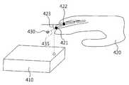
도 4를 참조하면, 일 실시예에 따른 3차원 입체 영상 표시 장치(410)는 입력 객체(420)에 포함된 유효 입력 포인트(421) 및 유효 관절 포인트(422)를 추출할 수 있다. 여기서, 입력 객체(420)는 적어도 하나의 관절을 포함하고, 유효 관절 포인트(422)는 유효 입력 포인트(421)와 가장 인접한 관절에 해당하는 포인트를 포함할 수 있다.Referring to FIG. 4, the three-dimensional
또한, 3차원 입체 영상 표시 장치(410)는 유효 입력 포인트(421)의 위치와 유효 관절 포인트(422)의 위치를 추정할 수 있다. 3차원 입체 영상 표시 장치(410)는 유효 입력 포인트(421)의 위치와 유효 관절 포인트(422)의 위치를 이용하여 입력 객체(420)의 마지막 마디의 오리엔테이션을 추정할 수 있다.In addition, the three-dimensional
예를 들어, 입력 객체(420)가 사람의 손가락인 경우 3차원 입체 영상 표시 장치(410)는 유효 입력 포인트(421)의 위치로부터 유효 관절 포인트(422)의 위치로 향하는 벡터를 생성함으로써 손가락의 마지막 마디의 오리엔테이션을 모델링 할 수 있다.For example, when the
나아가, 3차원 입체 영상 표시 장치(410)는 추정된 유효 입력 포인트(421)의 위치로부터 벡터의 방향(423)으로 보정 값(435)만큼 떨어진 위치를 시각적 인디케이터(430)의 위치로 결정할 수 있다.Further, the three-dimensional
예를 들어, 3차원 입체 영상 표시 장치(410)는 하기 수학식 5를 이용하여 시각적 인디케이터(430)의 위치를 계산할 수 있다.
For example, the three-dimensional

여기서, (x'', y'', z'')는 입력 객체(420)의 마지막 마디의 모델링 결과 생성된 벡터의 방향(423)을 가지는 단위 벡터이다.Here, (x ", y", z ") is a unit vector having a
다른 실시예에 따른 3차원 입체 영상 표시 장치(410)는 복수의 시각적 인디케이터들 각각의 위치를 계산할 수 있고, 이 경우 3차원 입체 영상 표시 장치(410)는 각각의 시각적 인디케이터를 서로 구분되도록 표시할 수 있다. 예를 들어, 3차원 입체 영상 표시 장치(410)는 각각의 시각적 인디케이터를 서로 다른 색상 또는 서로 다른 모양으로 표시할 수 있다.
The three-dimensional
도 5를 참조하면, 일 실시예에 따른 3차원 입체 영상 표시 장치(510)는 입력 객체(520)에 포함된 유효 입력 곡면(525)를 추출할 수 있다. 여기서, 유효 입력 곡면(525)은 입력 객체(520)의 끝부분에 해당하는 표면으로, 예를 들어 입력 객체(520)가 사람의 손가락인 경우 해당 손가락의 끝부분에 해당하는 곡면을 포함할 수 있다.Referring to FIG. 5, the three-dimensional
3차원 입체 영상 표시 장치(510)는 추출된 유효 입력 곡면(525)을 복수의 평면들로 분할할 수 있다. 예를 들어, 3차원 입체 영상 표시 장치(510)는 삼각측량법을 통해 유효 입력 곡면(525)을 위한 복수의 메쉬(mesh)들을 생성할 수 있다.The three-dimensional
또한, 3차원 입체 영상 표시 장치(510)는 분할된 복수의 평면들의 노멀 벡터들을 추정할 수 있다. 예를 들어, 3차원 입체 영상 표시 장치(510)는 삼각측량법을 통해 생성된 복수의 메쉬들 각각의 노멀 벡터를 계산할 수 있다.In addition, the three-dimensional
나아가, 3차원 입체 영상 표시 장치(510)는 복수의 평면들 각각의 중심점으로부터 해당 노멀 벡터의 방향으로 보정 값만큼 떨어진 위치를 시각적 인디케이터 (530)의 위치로 결정할 수 있다.Further, the three-dimensional
이 경우, 3차원 입체 영상 표시 장치(510)는 유효 입력 곡면(525)과 평행하고 유효 입력 곡면(525)의 면적보다 더 큰 면적을 가지는 시각적 인디케이터(530)를 표시할 수 있다.In this case, the three-dimensional
다른 실시예에 따른 3차원 입체 영상 표시 장치(510)는 복수의 입력 객체들에 대응되는 복수의 유효 입력 곡면들을 추출할 수 있다. 3차원 입체 영상 표시 장치(510)는 각각의 유효 입력 곡면들에 대응되는 시각적 인디케이터를 서로 구분되도록 표시할 수 있다. 예를 들어, 3차원 입체 영상 표시 장치(510)는 각각의 시각적 인디케이터를 서로 다른 색상으로 표시할 수 있다.
The three-dimensional
도 6은 일 실시예에 따른 입력 객체를 감지하는 경우 시각적 인디케이터를 표시하는 방법을 설명하기 위한 도면이다.6 is a view for explaining a method of displaying a visual indicator when detecting an input object according to an embodiment.
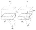
도 6을 참조하면, 일 실시예에 따른 3차원 입체 영상 표시 장치(610)는 입력 객체(620)가 미리 정해진 3차원 입체 영상 표시 공간(615)으로 진입하는 것을 감지할 수 있다.Referring to FIG. 6, the three-dimensional
이 때, 3차원 입체 영상 표시 장치(610)는 입력 객체(620)가 미리 정해진 3차원 입체 영상 표시 공간(615)으로 진입하는 것을 감지함에 따라 시각적 인디케이터(630)를 표시할지 여부를 판단할 수 있다.At this time, the three-dimensional
이로 인해서, 3차원 입체 영상 표시 장치(610)는 3차원 인식 공간이 아닌 3차원 입체 영상 표시 공간(615)을 인터액션 영역(interaction region)으로 설정할 수 있다. 인터액션 영역은 입력 객체를 이용하여 입체 영상 객체를 조작할 수 있는 인터페이스가 제공되는 영역이다.Accordingly, the three-dimensional
일 실시예에 따르면, 3차원 인식 공간은 3차원 입체 영상 표시 공간(615)보다 더 클 수 있다. 이 경우, 3차원 입체 영상 표시 장치(610)는 입력 객체(620)가 인터액션 영역인 3차원 입체 영상 표시 공간(615)으로 진입하기 이전부터 3차원 인식 공간 내에 진입한 입력 객체(620)를 인식할 수 있다.
According to one embodiment, the three-dimensional recognition space may be larger than the three-dimensional
도 7은 일 실시예에 따른 시각적 인디케이터를 이용하여 입체 영상 객체를 선택하는 방법을 설명하기 위한 도면이다.7 is a view for explaining a method of selecting a stereoscopic image object using a visual indicator according to an embodiment.
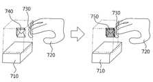
도 7을 참조하면, 일 실시예에 따른 3차원 입체 영상 표시 장치(710)는 시각적 인디케이터(730)의 위치에 기초하여 시각적 인디케이터(730)가 입체 영상 객체(740)와 접촉되는지 여부를 판단할 수 있다.Referring to FIG. 7, the three-dimensional
이로 인하여, 일 실시예에 따른 3차원 입체 영상 표시 장치(710)는 입력 객체(720)가 아닌 시각적 인디케이터(730)를 이용하여 입체 영상 객체(740)를 제어하는 기술을 제공할 수 있다.Accordingly, the three-dimensional
보다 구체적으로, 일 실시예에 따른 3차원 입체 영상 표시 장치(710)는 이용자에게 시각적 인디케이터(730)를 피드백 함으로써, 입력 객체(720)의 위치 추정 오차가 존재하는 상황에서 이용자가 입체 영상 객체(740)를 조작할 때 느낄 수 있는 접촉 괴리감을 감소시키는 기술을 제공할 수 있다.More specifically, the three-dimensional
이 때, 3차원 입체 영상 표시 장치(710)는 시각적 인디케이터(730)와 입체 영상 객체 사이의 거리를 계산하고, 계산된 거리가 미리 정해진 문턱 값 이하인 경우 시각적 인디케이터(730)와 입체 영상 객체(740)가 접촉되었다고 판단할 수 있다.At this time, the three-dimensional
3차원 입체 영상 표시 장치(710)는 시각적 인디케이터(730)와 입체 영상 객체(740)가 접촉되었다는 판단에 따라 입체 영상 객체(740)를 제어할 수 있다.The three-dimensional
보다 구체적으로, 3차원 입체 영상 표시 장치(710)는 시각적 인디케이터(730)와 입체 영상 객체(740)가 접촉되었다는 판단에 따라 입체 영상 객체(740)가 선택되도록 제어할 수 있다.More specifically, the three-dimensional
이 경우, 3차원 입체 영상 표시 장치(710)는 시각적 인디케이터(730) 또는 선택된 입체 영상 객체(750) 중 적어도 하나에 시각적 효과를 부가할 수 있다. 예를 들어, 3차원 입체 영상 표시 장치(710)는 선택된 입체 영상 객체(750)의 표면의 색상을 시각적 인디케이터(730)에 대응되는 색상이 강조되도록 변경시킬 수 있다. 또는, 3차원 입체 영상 표시 장치(710)는 시각적 인디케이터(730)의 크기, 모양, 색상 등을 변경시킬 수 있다. 또는, 3차원 입체 영상 표시 장치(710)는 이용자의 시선 방향을 추정하고, 추정된 시선 방향을 기준으로 가시적인 영역에 해당하는 표면에만 시각적 효과를 부가할 수 있다.In this case, the three-dimensional
3차원 입체 영상 표시 장치(710)는 제어된 입체 영상 객체(750)와 시각적 인디케이터(730)를 포함하는 3차원 입체 영상을 생성할 수 있고, 생성된 3차원 입체 영상을 3차원 입체 영상 표시 공간에 표시할 수 있다.Dimensional stereoscopic
도면에 표시하지 않았으나, 다른 실시예에 따른 3차원 입체 영상 표시 장치는 복수의 입력 객체들을 인식할 수 있다. 3차원 입체 영상 표시 장치는 복수의 입력 객체들에 대응되는 복수의 시각적 인디케이터들의 위치를 결정할 수 있다.Although not shown in the drawing, the three-dimensional image display apparatus according to another embodiment can recognize a plurality of input objects. The three-dimensional image display apparatus can determine a position of a plurality of visual indicators corresponding to a plurality of input objects.
이 경우, 3차원 입체 영상 표시 장치는 복수의 시각적 인디케이터들을 서로 구별되도록 표시할 수 있다. 예를 들어, 3차원 입체 영상 표시 장치는 복수의 시각적 인디케이터들 각각의 색상, 모양, 크기 등을 다르게 표시할 수 있다.In this case, the three-dimensional image display apparatus can display a plurality of visual indicators so as to be distinguished from each other. For example, the three-dimensional image display apparatus may display the color, shape, size, etc. of each of the plurality of visual indicators differently.
나아가, 3차원 입체 영상 표시 장치는 복수의 시각적 인디케이터들과 복수의 입체 영상 객체들이 접촉되는지 여부를 판단할 수 있고, 상이한 시각적 인디케이터에 의해 접촉된 입체 영상 객체들 각각에 서로 다른 시각적 효과를 부가할 수 있다.Further, the three-dimensional image display apparatus can determine whether a plurality of visual indicators and a plurality of stereoscopic image objects are in contact with each other, and add different visual effects to each of the stereoscopic image objects contacted by the different visual indicators .
예를 들어, 3차원 입체 영상 표시 장치는 제1 시각적 인디케이터와 접촉된 입체 영상 객체에 제1 시각적 인디케이터에 대응되는 시각적 효과를 부가하고, 제2 시각적 인디케이터와 접촉된 입체 영상 객체에는 제2 시각적 인디케이터에 대응되는 시각적 효과를 부가할 수 있다. 간단하게는, 3차원 입체 영상 표시 장치는 제1 시각적 인디케이터에 대응되는 시각적 효과로 빨간색을 강조하는 효과를 이용할 수 있고, 제2 시각적 인디케이터에 대응되는 시각적 효과로 파란색을 강조하는 효과를 이용할 수 있다.For example, the 3D stereoscopic image display device adds a visual effect corresponding to the first visual indicator to the stereoscopic image object in contact with the first visual indicator, and adds a second visual indicator to the stereoscopic image object in contact with the second visual indicator, It is possible to add a visual effect corresponding to the image. Briefly, the three-dimensional image display apparatus can utilize an effect of emphasizing red with a visual effect corresponding to the first visual indicator, and an effect of emphasizing blue with a visual effect corresponding to the second visual indicator .
나아가, 3차원 입체 영상 표시 장치는 상이한 시각적 인디케이터에 의해 접촉된 입체 영상 객체들 각각을 해당 시각적 인디케이터에 종속시킴으로써, 다양한 유저 인터페이스를 제공할 수 있다.Furthermore, the three-dimensional image display apparatus can provide various user interfaces by subordinating each of the three-dimensional image objects touched by the different visual indicators to the corresponding visual indicator.
또 다른 실시예에 따른 3차원 입체 영상 표시 장치는 시각적 인터페이스가 입체 영상 객체와 접촉되었다는 판단에 따라 입력 객체로 햅틱(haptic) 피드백을 제공할 수 있다. 예를 들어, 3차원 입체 영상 표시 장치는 공기 팬(air fan)이나 초음파 어레이(array)를 이용하여 해당 입력 객체로 햅틱 피드백을 제공할 수 있다.According to another embodiment, the three-dimensional image display apparatus may provide haptic feedback to an input object according to a determination that the visual interface is in contact with the stereoscopic image object. For example, the three-dimensional image display apparatus can provide haptic feedback to a corresponding input object using an air fan or an ultrasonic array.
또 다른 실시예에 따른 3차원 입체 영상 표시 장치는 시각적 인터페이스가 입체 영상 객체와 접촉되었다는 판단에 따라 오디오 피드백을 제공할 수 있다. 예를 들어, 3차원 입체 영상 표시 장치는 미리 정해진 효과음을 재생할 수 있다.
The three-dimensional image display apparatus according to another embodiment may provide audio feedback according to a determination that the visual interface is in contact with the stereoscopic image object. For example, the three-dimensional image display apparatus can reproduce predetermined sound effects.
도 8은 일 실시예에 따른 시각적 인디케이터를 이용하여 입체 영상 객체를 이동시키는 방법을 설명하기 위한 도면이다.FIG. 8 is a view for explaining a method of moving a stereoscopic image object using a visual indicator according to an embodiment.
도 8을 참조하면, 일 실시예에 따른 3차원 입체 영상 표시 장치는 복수의 시각적 인디케이터들(831, 832, 833) 각각과 입체 영상 객체(810)가 접촉되는지 여부를 판단할 수 있다.Referring to FIG. 8, the three-dimensional image display apparatus according to an exemplary embodiment may determine whether each of the plurality of
3차원 입체 영상 표시 장치는 입체 영상 객체(810)와 접촉된 시각적 인디케이터(832, 833)와 접촉되지 않은 시각적 인디케이터(831)에 상이한 시각적 효과를 부가할 수 있다. 예를 들어, 3차원 입체 영상 표시 장치는 입체 영상 객체(810)와 접촉된 시각적 인디케이터(832, 833)를 하이라이트 함으로써, 이용자에게 해당 시각적 인디케이터가 특정 입체 영상 객체에 접촉되었음을 알릴 수 있다.The three-dimensional image display device may add different visual effects to the
도 7을 통하여 전술한 바와 같이, 3차원 입체 영상 표시 장치는 입력 객체(820)와 입체 영상 객체(810) 사이의 접촉을 판단하는 대신 시각적 인디케이터들(831, 832, 833)과 입체 영상 객체(810) 사이의 접촉을 판단할 수 있다.As described above with reference to FIG. 7, instead of determining the contact between the
뿐만 아니라, 3차원 입체 영상 표시 장치는 적어도 두 개의 시각적 인디케이터들이 입체 영상 객체와 접촉되는 경우 해당 입체 영상 객체가 이동되도록 제어할 수 있다.In addition, the three-dimensional image display apparatus can control the stereoscopic image object to move when at least two visual indicators are in contact with the stereoscopic image object.
이 경우, 3차원 입체 영상 표시 장치는 해당 입체 영상 객체와 접촉된 적어도 두 개의 시각적 인디케이터들의 위치 변화에 따라 해당 입체 영상 객체를 이동시킬 수 있다.In this case, the three-dimensional image display apparatus can move the stereoscopic image object according to a change in position of at least two visual indicators in contact with the stereoscopic image object.
예를 들어, 이용자는 중지에 대응되는 시각적 인디케이터(832)와 엄지 손가락에 대응되는 시각적 인디케이터(833)를 입체 영상 객체(810)에 접촉시킨 뒤, 접촉을 유지하면서 중지와 엄지를 움직임으로써 해당 입체 영상 객체(810)를 3차원 입체 영상 표시 공간 내에서 이동시킬 수 있다.For example, the user touches the
도면에 표시하지 않았으나, 다른 실시예에 따른 3차원 입체 영상 표시 장치는 시각적 인디케이터가 입체 영상 객체와 충돌되는지 여부를 판단할 수 있다. 3차원 입체 영상 표시 장치는 시각적 인디케이터가 입체 영상 객체와 충돌되었다는 판단에 따라 해당 입체 영상 객체가 물리 법칙에 따라 이동 또는 변형되도록 제어할 수 있다.Although not shown in the drawing, the three-dimensional image display apparatus according to another embodiment can determine whether a visual indicator is collided with a stereoscopic image object. The three-dimensional image display apparatus can control the stereoscopic image object to be moved or deformed according to a physical rule according to the determination that the visual indicator collides with the stereoscopic image object.
이 경우, 3차원 입체 영상 표시 장치는 시각적 인디케이터와 입체 영상 객체 사이의 충돌과 관련된 정보에 기초하여 해당 입체 영상 객체를 이동시키거나 변형시킬 수 있다. 예를 들어, 3차원 입체 영상 표시 장치는 물리 엔진에 시각적 인디케이터와 입체 영상 객체 사이의 충돌과 관련된 정보를 입력함으로써 해당 입체 영상 객체가 물리학적으로 어떤 영향을 받을지 여부를 시뮬레이션 할 수 있고, 그 결과를 표시할 수 있다.
In this case, the three-dimensional image display apparatus can move or modify the stereoscopic image object based on information related to a collision between the visual indicator and the stereoscopic image object. For example, a 3D stereoscopic image display device can input information related to a collision between a visual indicator and a stereoscopic image object to a physical engine, thereby simulating how the stereoscopic image object is physically affected, Can be displayed.
도 9는 일 실시예에 따른 시각적 인디케이터를 이용하여 입체 영상 객체와의 근접 여부를 표시하는 방법을 설명하기 위한 도면이다.FIG. 9 is a view for explaining a method of displaying proximity to a stereoscopic image object using a visual indicator according to an embodiment.
도 9를 참조하면, 일 실시예에 따른 3차원 입체 영상 표시 장치는 시각적 인디케이터의 위치에 기초하여 시각적 인디케이터와 입체 영상 객체 사이의 거리를 계산할 수 있다.Referring to FIG. 9, the three-dimensional image display apparatus according to an exemplary embodiment may calculate the distance between the visual indicator and the stereoscopic image object based on the position of the visual indicator.
나아가, 3차원 입체 영상 표시 장치는 계산된 거리에 따라 해당 시각적 인디케이터의 외관을 제어할 수 있다. 이로 인하여, 일 실시예에 따른 3차원 입체 영상 표시 장치는 시각적 인디케이터의 외관을 통해 시각적 인디케이터와 입체 영상 객체 사이의 거리를 표시할 수 있다.Furthermore, the three-dimensional image display apparatus can control the appearance of the visual indicator according to the calculated distance. Accordingly, the three-dimensional image display apparatus according to an exemplary embodiment can display the distance between the visual indicator and the stereoscopic image object through the appearance of the visual indicator.
예를 들어, 3차원 입체 영상 표시 장치는 시각적 인디케이터의 크기를 통해 입력 객체와 입체 영상 객체 사이의 근접 여부를 표시할 수 있다.For example, the three-dimensional image display apparatus can display the proximity between the input object and the stereoscopic image object through the size of the visual indicator.
이용자의 왼손(920) 엄지보다 이용자의 오른손(940) 엄지가 입체 영상 객체(910)에 더 가까이 접근해 있는 경우를 가정하자. 이 경우, 이용자의 왼손(920) 엄지에 대응되는 시각적 인디케이터(930)의 크기보다 이용자의 오른손(940) 엄지에 대응되는 시각적 인디케이터(950)의 크기가 더 크게 표시될 수 있다.
Suppose that the thumb of the user's
도 10은 일 실시예에 따른 입력 객체의 자세에 따라 시각적 인디케이터의 유형을 변경하는 3차원 입체 영상 표시 방법을 설명하기 위한 도면이다.10 is a view for explaining a three-dimensional stereoscopic image display method for changing the type of a visual indicator according to an attitude of an input object according to an exemplary embodiment.
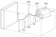
도 10을 참조하면, 일 실시예에 따른 3차원 입체 영상 표시 장치는 입력 객체의 자세를 인식할 수 있다. 여기서, 3차원 입체 영상 표시 장치는 이용자의 손을 입력 객체로 인식한 이후, 미리 정해진 다양한 패턴의 손 모양을 인식할 수 있다. 예를 들어, 3차원 입체 영상 표시 장치는 주먹을 쥐고 있는 손 모양, 펜을 쥐고 있는 손 모양, 총의 형상을 묘사한 손 모양 등 다양한 패턴의 손 모양을 인식할 수 있다.Referring to FIG. 10, the three-dimensional image display apparatus according to an exemplary embodiment can recognize an orientation of an input object. Here, the 3D stereoscopic image display device recognizes the hand of the user as an input object, and then recognizes hand shapes of predetermined patterns. For example, the three-dimensional image display device can recognize hand patterns of various patterns such as a hand shape holding a fist, a hand shape holding a pen, and a hand shape depicting a shape of a gun.
이 경우, 3차원 입체 영상 표시 장치는 인식한 입력 객체의 자세에 대응되는 시각적 인디케이터의 유형을 결정할 수 있다. 여기서, 3차원 입체 영상 표시 장치는 시각적 인디케이터의 유형에 따라 시각적 인디케이터의 형태 또는 시각적 인디케이터의 기능을 달리할 수 있다.In this case, the three-dimensional image display apparatus can determine the type of the visual indicator corresponding to the recognized posture of the input object. Here, the three-dimensional image display apparatus may have different functions of the visual indicator or the visual indicator depending on the type of the visual indicator.
예를 들어, 3차원 입체 영상 표시 장치는 펜을 쥐고 있는 손 모양(1010)을 인식하는 경우, 시각적 인디케이터를 펜 모양으로 결정할 수 있다. 나아가, 3차원 입체 영상 표시 장치는 펜 모양의 시각적 인디케이터(1020)가 움직이는 궤적을 따라 선(1030)이 그려지도록 할 수 있다.
For example, when the three-dimensional image display device recognizes the
도 11은 일 실시예에 따른 시각적 인디케이터를 이용하여 사용자 인터페이스를 제공하는 3차원 입체 영상 표시 방법을 나타낸 동작 흐름도이다.11 is a flowchart illustrating a method of displaying a three-dimensional image by providing a user interface using a visual indicator according to an exemplary embodiment of the present invention.
도 11을 참조하면, 일 실시예에 따른 3차원 입체 영상 표시 방법은 입력 객체를 인식하는 단계(1110), 시각적 인디케이터의 위치를 결정하는 단계(1120) 및 시각적 인디케이터를 표시하는 단계(1130)를 포함한다.Referring to FIG. 11, a 3D stereoscopic image display method according to an exemplary embodiment includes a
입력 객체를 인식하는 단계(1110)는 미리 정해진 3차원 인식 공간 내에서 입력 객체를 인식할 수 있다. 시각적 인디케이터의 위치를 결정하는 단계(1120)는 인식된 입력 객체에 기초하여 미리 정해진 3차원 입체 영상 표시 공간 내 시각적 인디케이터의 위치를 결정할 수 있다. 시각적 인디케이터를 표시하는 단계(1130)는 결정된 시각적 인디케이터의 위치에 기초하여 미리 정해진 3차원 입체 영상 표시 공간에 해당 시각적 인디케이터를 표시할 수 있다.The
도 11에 도시된 각 단계들에는 도 1 내지 도 10을 통하여 기술된 사항들이 그대로 적용될 수 있으므로, 보다 상세한 설명은 생략한다.The steps described in FIG. 1 through FIG. 10 may be applied to each step shown in FIG. 11, so that a detailed description will be omitted.
실시예에 따른 방법은 다양한 컴퓨터 수단을 통하여 수행될 수 있는 프로그램 명령 형태로 구현되어 컴퓨터 판독 가능 매체에 기록될 수 있다. 상기 컴퓨터 판독 가능 매체는 프로그램 명령, 데이터 파일, 데이터 구조 등을 단독으로 또는 조합하여 포함할 수 있다. 상기 매체에 기록되는 프로그램 명령은 실시예를 위하여 특별히 설계되고 구성된 것들이거나 컴퓨터 소프트웨어 당업자에게 공지되어 사용 가능한 것일 수도 있다. 컴퓨터 판독 가능 기록 매체의 예에는 하드 디스크, 플로피 디스크 및 자기 테이프와 같은 자기 매체(magnetic media), CD-ROM, DVD와 같은 광기록 매체(optical media), 플롭티컬 디스크(floptical disk)와 같은 자기-광 매체(magneto-optical media), 및 롬(ROM), 램(RAM), 플래시 메모리 등과 같은 프로그램 명령을 저장하고 수행하도록 특별히 구성된 하드웨어 장치가 포함된다. 프로그램 명령의 예에는 컴파일러에 의해 만들어지는 것과 같은 기계어 코드뿐만 아니라 인터프리터 등을 사용해서 컴퓨터에 의해서 실행될 수 있는 고급 언어 코드를 포함한다. 상기된 하드웨어 장치는 실시예의 동작을 수행하기 위해 하나 이상의 소프트웨어 모듈로서 작동하도록 구성될 수 있으며, 그 역도 마찬가지이다.The method according to an embodiment may be implemented in the form of a program command that can be executed through various computer means and recorded in a computer-readable medium. The computer-readable medium may include program instructions, data files, data structures, and the like, alone or in combination. The program instructions to be recorded on the medium may be those specially designed and configured for the embodiments or may be available to those skilled in the art of computer software. Examples of computer-readable media include magnetic media such as hard disks, floppy disks and magnetic tape; optical media such as CD-ROMs and DVDs; magnetic media such as floppy disks; Magneto-optical media, and hardware devices specifically configured to store and execute program instructions such as ROM, RAM, flash memory, and the like. Examples of program instructions include machine language code such as those produced by a compiler, as well as high-level language code that can be executed by a computer using an interpreter or the like. The hardware devices described above may be configured to operate as one or more software modules to perform the operations of the embodiments, and vice versa.
이상과 같이 실시예들이 비록 한정된 실시예와 도면에 의해 설명되었으나, 해당 기술분야에서 통상의 지식을 가진 자라면 상기의 기재로부터 다양한 수정 및 변형이 가능하다. 예를 들어, 설명된 기술들이 설명된 방법과 다른 순서로 수행되거나, 및/또는 설명된 시스템, 구조, 장치, 회로 등의 구성요소들이 설명된 방법과 다른 형태로 결합 또는 조합되거나, 다른 구성요소 또는 균등물에 의하여 대치되거나 치환되더라도 적절한 결과가 달성될 수 있다.While the present invention has been particularly shown and described with reference to exemplary embodiments thereof, it is to be understood that the invention is not limited to the disclosed exemplary embodiments. For example, it is to be understood that the techniques described may be performed in a different order than the described methods, and / or that components of the described systems, structures, devices, circuits, Lt; / RTI > or equivalents, even if it is replaced or replaced.
그러므로, 다른 구현들, 다른 실시예들 및 특허청구범위와 균등한 것들도 후술하는 특허청구범위의 범위에 속한다.
Therefore, other implementations, other embodiments, and equivalents to the claims are also within the scope of the following claims.
Claims (28)
Translated fromKorean미리 정해진 3차원 인식 공간 내에서 입력 객체를 인식하는 인식부;
상기 입력 객체에 포함된 유효 입력 포인트의 위치를 추정하고, 상기 유효 입력 포인트의 위치 및 상기 시각적 인디케이터를 위한 보정 값에 기초하여 미리 정해진 3차원 입체 영상 표시 공간 내 상기 시각적 인디케이터의 위치를 결정하는 결정부;
상기 시각적 인디케이터의 위치에 기초하여 상기 미리 정해진 3차원 입체 영상 표시 공간에 상기 시각적 인디케이터를 표시하는 표시부;
상기 시각적 인디케이터와 상기 3차원 입체 영상 표시 공간 내 배치된 입체 영상 객체 사이의 제1 거리를 계산하고, 상기 제1 거리가 임계 값보다 작은지 여부를 판단함으로써, 상기 시각적 인디케이터가 상기 입체 영상 객체와 접촉하였는지 여부를 판단하는 판단부; 및
상기 시각적 인디케이터가 상기 입체 영상 객체와 접촉함에 반응하여, 상기 입체 영상 객체를 제어하는 제어부
를 포함하고,
상기 시각적 인디케이터의 위치는 상기 유효 입력 포인트의 위치로부터 상기 시각적 인디케이터를 위한 보정 값에 대응하는 제2 거리만큼 이격되도록 결정되는 3차원 입체 영상 표시 장치.A three-dimensional image display apparatus for providing a user interface using a visual indicator,
A recognition unit for recognizing an input object within a predetermined three-dimensional recognition space;
Determining a position of the visual indicator in a predetermined three-dimensional image display space based on the position of the valid input point and the correction value for the visual indicator, estimating a position of the effective input point included in the input object, part;
A display unit for displaying the visual indicator in the predetermined three-dimensional image display space based on the position of the visual indicator;
Calculating a first distance between the visual indicator and a stereoscopic image object disposed in the three-dimensional image display space, and determining whether the first distance is less than a threshold value, A judgment unit for judging whether or not the contact has been made; And
A controller for controlling the stereoscopic image object in response to the visual indicator contacting the stereoscopic image object,
Lt; / RTI >
Wherein the position of the visual indicator is determined to be spaced from the position of the valid input point by a second distance corresponding to a correction value for the visual indicator.
상기 유효 입력 포인트는 상기 입력 객체의 끝에 해당하는 포인트를 포함하는 3차원 입체 영상 표시 장치.The method according to claim 1,
Wherein the effective input point includes a point corresponding to an end of the input object.
상기 보정 값은 제1 축에 대응하는 제1 추정 오차, 제2 축에 대응하는 제2 추정 오차, 및 제3 축에 대응하는 제3 추정 오차에 기초하여 결정되는 3차원 입체 영상 표시 장치.The method according to claim 1,
Wherein the correction value is determined based on a first estimation error corresponding to the first axis, a second estimation error corresponding to the second axis, and a third estimation error corresponding to the third axis.
상기 결정부에 포함된 추출부는 상기 입력 객체에 포함된 유효 관절 포인트를 더 추출하고,
상기 결정부에 포함된 추정부는 상기 유효 관절 포인트의 위치를 더 추정하며,
상기 시각적 인디케이터 위치 계산부는 상기 유효 관절 포인트의 위치로부터 상기 유효 입력 포인트의 위치로 향하는 벡터의 방향에 더 기초하여 상기 시각적 인디케이터의 위치를 계산하는 3차원 입체 영상 표시 장치.The method according to claim 1,
Wherein the extracting unit included in the determining unit further extracts the effective joint points included in the input object,
Wherein the estimating unit included in the determining unit further estimates the position of the effective joint point,
Wherein the visual indicator position calculation unit calculates a position of the visual indicator based on a direction of a vector from a position of the effective joint point to a position of the effective input point.
상기 입력 객체는 적어도 하나의 관절을 포함하고, 상기 유효 관절 포인트는 상기 유효 입력 포인트와 가장 인접한 관절에 해당하는 포인트를 포함하는 3차원 입체 영상 표시 장치.6. The method of claim 5,
Wherein the input object includes at least one joint, and the effective joint point includes a point corresponding to a joint closest to the valid input point.
미리 정해진 3차원 인식 공간 내에서 입력 객체를 인식하는 인식부;
상기 입력 객체에 기초하여 미리 정해진 3차원 입체 영상 표시 공간 내 상기 시각적 인디케이터의 위치를 결정하는 결정부; 및
상기 시각적 인디케이터의 위치에 기초하여 상기 미리 정해진 3차원 입체 영상 표시 공간에 상기 시각적 인디케이터를 표시하는 표시부
를 포함하고,
상기 결정부는
상기 입력 객체에 포함된 유효 입력 곡면을 추출하는 추출부;
상기 유효 입력 곡면을 복수의 평면들로 분할하는 분할부;
상기 복수의 평면들의 노멀 벡터들을 추정하는 추정부; 및
상기 복수의 평면들의 중심점들, 상기 노멀 벡터들의 방향들 및 상기 시각적 인디케이터를 위한 보정 값에 기초하여 상기 시각적 인디케이터의 위치를 계산하는 시각적 인디케이터 위치 계산부
를 포함하는 3차원 입체 영상 표시 장치.A three-dimensional image display apparatus for providing a user interface using a visual indicator,
A recognition unit for recognizing an input object within a predetermined three-dimensional recognition space;
A determining unit for determining a position of the visual indicator in a predetermined three-dimensional image display space based on the input object; And
A display unit for displaying the visual indicator in the predetermined three-dimensional image display space based on the position of the visual indicator;
Lt; / RTI >
The determination unit
An extracting unit for extracting an effective input curved surface included in the input object;
A dividing unit dividing the effective input curved surface into a plurality of planes;
An estimating unit estimating normal vectors of the plurality of planes; And
A visual indicator position calculator for calculating the position of the visual indicator based on the center points of the plurality of planes, the directions of the normal vectors, and the correction value for the visual indicator,
Dimensional stereoscopic image display device.
상기 유효 입력 곡면은 상기 입력 객체의 끝부분에 해당하는 표면을 포함하는 3차원 입체 영상 표시 장치.8. The method of claim 7,
Wherein the effective input curved surface includes a surface corresponding to an end portion of the input object.
상기 입력 객체가 상기 미리 정해진 3차원 입체 영상 표시 공간으로 진입하는 것을 감지하는 감지부; 및
상기 감지 결과에 따라 상기 시각적 인디케이터를 표시할지 여부를 판단하는 판단부
를 더 포함하고,
상기 미리 정해진 3차원 인식 공간은 상기 미리 정해진 3차원 입체 영상 표시 공간보다 큰 3차원 입체 영상 표시 장치.The method according to claim 1,
A sensing unit sensing that the input object enters the predetermined three-dimensional image display space; And
A determination unit for determining whether to display the visual indicator according to the detection result,
Further comprising:
Dimensional stereoscopic image display space, wherein the predetermined three-dimensional recognition space is larger than the predetermined three-dimensional stereoscopic image display space.
상기 표시부는 상기 제어 결과에 기초하여 상기 입체 영상 객체와 상기 시각적 인디케이터를 포함하는 3차원 입체 영상을 생성하는 3차원 입체 영상 표시 장치.The method according to claim 1,
And the display unit generates a three-dimensional image including the stereoscopic image object and the visual indicator based on the control result.
상기 제어부는 상기 시각적 인디케이터가 상기 입체 영상 객체와 접촉되었다는 판단에 따라 상기 입체 영상 객체가 선택되도록 제어하고,
상기 표시부는 상기 입체 영상 객체가 선택되도록 제어되는 경우 상기 시각적 인디케이터 또는 상기 입체 영상 객체 중 적어도 하나에 시각적 효과가 부가된 3차원 입체 영상을 생성하는 3차원 입체 영상 표시 장치.11. The method of claim 10,
Wherein the control unit controls the stereoscopic image object to be selected according to a determination that the visual indicator is in contact with the stereoscopic image object,
Wherein the display unit generates a three-dimensional image having a visual effect added to at least one of the visual indicator and the stereoscopic image object when the stereoscopic image object is controlled to be selected.
상기 인식부는 상기 입력 객체와 구별되는 제2 입력 객체를 더 인식하고,
상기 결정부는 상기 제2 입력 객체에 대응되는 제2 시각적 인디케이터의 위치를 더 결정하며,
상기 표시부는 상기 시각적 인디케이터와 상기 제2 시각적 인디케이터를 서로 구별되도록 표시하는 3차원 입체 영상 표시 장치.11. The method of claim 10,
Wherein the recognizing unit further recognizes a second input object distinguished from the input object,
Wherein the determining unit further determines a position of a second visual indicator corresponding to the second input object,
Wherein the display unit displays the visual indicator and the second visual indicator so as to be distinguished from each other.
상기 판단부는 상기 제2 시각적 인디케이터의 위치에 더 기초하여 상기 제2 시각적 인디케이터가 상기 입체 영상 객체와 구별되는 제2 입체 영상 객체에 접촉되는지 여부를 더 판단하고,
상기 제어부는 상기 제2 시각적 인디케이터가 상기 제2 입체 영상 객체와 접촉되었다는 판단에 따라 상기 제2 입체 영상 객체가 상기 제2 시각적 인디케이터에 의해 선택되도록 제어하며,
상기 표시부는 상기 제2 입체 영상 객체가 상기 제2 시각적 인디케이터에 의해 선택되도록 제어되는 경우 상기 제2 시각적 인디케이터 또는 상기 제2 입체 영상 객체 중 적어도 하나에 상기 제2 시각적 인디케이터에 대응되는 시각적 효과가 부가된 3차원 입체 영상을 생성하는 3차원 입체 영상 표시 장치.13. The method of claim 12,
Wherein the determination unit further determines whether the second visual indicator is in contact with a second stereoscopic image object that is distinguished from the stereoscopic image object based further on the position of the second visual indicator,
Wherein the controller controls the second stereoscopic image object to be selected by the second visual indicator according to the determination that the second visual indicator is in contact with the second stereoscopic image object,
Wherein when the second stereoscopic image object is controlled to be selected by the second visual indicator, the display unit displays a visual effect corresponding to the second visual indicator on at least one of the second visual indicator or the second stereoscopic image object, Dimensional stereoscopic image is generated.
상기 판단부는 상기 제2 시각적 인디케이터의 위치에 더 기초하여 상기 시각적 인디케이터와 상기 제2 시각적 인디케이터가 상기 입체 영상 객체와 접촉되는지 여부를 판단하고,
상기 제어부는 상기 시각적 인디케이터와 상기 제2 시각적 인디케이터가 상기 입체 영상 객체와 접촉되었다는 판단에 따라 상기 입체 영상 객체가 이동되도록 제어하며,
상기 표시부는 상기 입체 영상 객체가 이동되도록 제어되는 경우 상기 시각적 인디케이터의 위치 변화와 상기 제2 시각적 인디케이터의 위치 변화에 따라 이동된 입체 영상 객체를 포함하는 3차원 입체 영상을 생성하는 3차원 입체 영상 표시 장치.13. The method of claim 12,
Wherein the determination unit determines whether the visual indicator and the second visual indicator are in contact with the stereoscopic image object based on the position of the second visual indicator,
Wherein the controller controls the stereoscopic image object to be moved according to a determination that the visual indicator and the second visual indicator are in contact with the stereoscopic image object,
The display unit displays a three-dimensional stereoscopic image, which is a three-dimensional stereoscopic image including a stereoscopic image object shifted according to a positional change of the visual indicator and a positional change of the second visual indicator when the stereoscopic image object is controlled to move, Device.
상기 판단부는 상기 시각적 인디케이터가 상기 입체 영상 객체와 충돌되는지 여부를 판단하고,
상기 제어부는 상기 시각적 인디케이터가 상기 입체 영상 객체와 충돌되었다는 판단에 따라 상기 입체 영상 객체가 물리 법칙에 따라 이동 또는 변형되도록 제어하며,
상기 표시부는 상기 입체 영상 객체가 물리 법칙에 따라 이동 또는 변형되도록 제어되는 경우 상기 충돌과 관련된 정보에 기초하여 이동 또는 변형된 입체 영상 객체를 포함하는 3차원 입체 영상을 생성하는 3차원 입체 영상 표시 장치.11. The method of claim 10,
Wherein the determination unit determines whether the visual indicator conflicts with the stereoscopic image object,
Wherein the control unit controls the stereoscopic image object to be moved or modified according to a physical rule according to a determination that the visual indicator collides with the stereoscopic image object,
Wherein the display unit is a three-dimensional image display device for generating a three-dimensional image including a stereoscopic image object that is moved or modified based on information related to the collision when the stereoscopic image object is controlled to be moved or deformed according to a physical law .
상기 시각적 인디케이터가 상기 입체 영상 객체와 접촉되었다는 판단에 따라 상기 입력 객체로 햅틱 피드백을 제공하는 햅틱 피드백부; 또는
상기 시각적 인디케이터가 상기 입체 영상 객체와 접촉되었다는 판단에 따라 오디오 피드백을 제공하는 오디오 피드백부
중 적어도 하나를 더 포함하는 3차원 입체 영상 표시 장치.11. The method of claim 10,
A haptic feedback unit for providing haptic feedback to the input object according to a determination that the visual indicator is in contact with the stereoscopic image object; or
An audio feedback unit for providing audio feedback according to a determination that the visual indicator is in contact with the stereoscopic image object,
Dimensional stereoscopic image display device.
상기 시각적 인디케이터의 위치에 기초하여 상기 시각적 인디케이터와 입체 영상 객체 사이의 거리를 계산하는 거리 계산부; 및
상기 거리에 따라 상기 시각적 인디케이터의 외관을 제어하는 제어부
를 더 포함하는 3차원 입체 영상 표시 장치.The method according to claim 1,
A distance calculator for calculating a distance between the visual indicator and the stereoscopic image object based on the position of the visual indicator; And
A controller for controlling the appearance of the visual indicator according to the distance,
Dimensional image display device.
상기 인식부는
상기 입력 객체의 자세를 인식하는 자세 인식부
를 포함하고,
상기 결정부는
상기 입력 객체의 자세에 대응되는 시각적 인디케이터의 유형을 결정하는 인디케이터 유형 결정부
를 포함하는 3차원 입체 영상 표시 장치.The method according to claim 1,
The recognition unit
An orientation recognition unit for recognizing the orientation of the input object,
Lt; / RTI >
The determination unit
An indicator type determining unit for determining a type of a visual indicator corresponding to the posture of the input object,
Dimensional stereoscopic image display device.
미리 정해진 3차원 인식 공간 내에서 입력 객체를 인식하는 단계;
상기 입력 객체에 포함된 유효 입력 포인트의 위치를 추정하는 단계;
상기 유효 입력 포인트의 위치 및 상기 시각적 인디케이터를 위한 보정 값에 기초하여 미리 정해진 3차원 입체 영상 표시 공간 내 상기 시각적 인디케이터의 위치를 결정하는 단계;
상기 시각적 인디케이터의 위치에 기초하여 상기 미리 정해진 3차원 입체 영상 표시 공간에 상기 시각적 인디케이터를 표시하는 단계;
상기 시각적 인디케이터와 상기 3차원 입체 영상 표시 공간 내 배치된 입체 영상 객체 사이의 제1 거리를 계산하는 단계;
상기 제1 거리가 임계 값보다 작은지 여부를 판단함으로써, 상기 시각적 인디케이터가 상기 입체 영상 객체와 접촉하였는지 여부를 판단하는 단계; 및
상기 시각적 인디케이터가 상기 입체 영상 객체와 접촉함에 반응하여, 상기 입체 영상 객체를 제어하는 단계
를 포함하고,
상기 시각적 인디케이터의 위치는 상기 유효 입력 포인트의 위치로부터 상기 시각적 인디케이터를 위한 보정 값에 대응하는 제2 거리만큼 이격되도록 결정되는 3차원 입체 영상 표시 방법.A three-dimensional image display method for providing a user interface using a visual indicator,
Recognizing an input object within a predetermined three-dimensional recognition space;
Estimating a position of a valid input point included in the input object;
Determining a position of the visual indicator in a predetermined three-dimensional image display space based on a position of the effective input point and a correction value for the visual indicator;
Displaying the visual indicator in the predetermined three-dimensional image display space based on the position of the visual indicator;
Calculating a first distance between the visual indicator and a stereoscopic image object disposed in the three-dimensional image display space;
Determining whether the visual indicator is in contact with the stereoscopic image object by determining whether the first distance is less than a threshold value; And
Controlling the stereoscopic image object in response to the visual indicator contacting the stereoscopic image object,
Lt; / RTI >
Wherein the position of the visual indicator is determined to be spaced from the position of the valid input point by a second distance corresponding to a correction value for the visual indicator.
상기 결정하는 단계는
상기 입력 객체로부터 유효 입력 포인트 및 유효 관절 포인트를 추출하는 단계;
상기 유효 입력 포인트의 위치 및 상기 유효 관절 포인트의 위치를 추정하는 단계; 및
상기 유효 관절 포인트의 위치로부터 상기 유효 입력 포인트의 위치로 향하는 벡터의 방향, 상기 유효 입력 포인트의 위치 및 상기 시각적 인디케이터를 위한 보정 값에 기초하여 상기 시각적 인디케이터의 위치를 계산하는 단계
를 포함하는 3차원 입체 영상 표시 방법.20. The method of claim 19,
The step of determining
Extracting a valid input point and an effective joint point from the input object;
Estimating a position of the effective input point and a position of the effective joint point; And
Calculating a position of the visual indicator based on a direction of a vector from a position of the effective joint point to a position of the valid input point, a position of the valid input point, and a correction value for the visual indicator
Dimensional stereoscopic image display method.
미리 정해진 3차원 인식 공간 내에서 입력 객체를 인식하는 단계;
상기 입력 객체에 기초하여 미리 정해진 3차원 입체 영상 표시 공간 내 상기 시각적 인디케이터의 위치를 결정하는 단계; 및
상기 시각적 인디케이터의 위치에 기초하여 상기 미리 정해진 3차원 입체 영상 표시 공간에 상기 시각적 인디케이터를 표시하는 단계
를 포함하고,
상기 결정하는 단계는
상기 입력 객체에 포함된 유효 입력 곡면을 추출하는 단계;
상기 유효 입력 곡면을 복수의 평면들로 분할하는 단계;
상기 복수의 평면들의 노멀 벡터들을 추정하는 단계; 및
상기 복수의 평면들의 중심점들, 상기 노멀 벡터들의 방향들 및 상기 시각적 인디케이터를 위한 보정 값에 기초하여 상기 시각적 인디케이터의 위치를 계산하는 단계
를 포함하는 3차원 입체 영상 표시 방법.A three-dimensional image display method for providing a user interface using a visual indicator,
Recognizing an input object within a predetermined three-dimensional recognition space;
Determining a position of the visual indicator in a predetermined three-dimensional image display space based on the input object; And
Displaying the visual indicator in the predetermined three-dimensional image display space based on the position of the visual indicator
Lt; / RTI >
The step of determining
Extracting an effective input curved surface included in the input object;
Dividing the effective input curved surface into a plurality of planes;
Estimating normal vectors of the plurality of planes; And
Calculating a position of the visual indicator based on the center points of the plurality of planes, the directions of the normal vectors and the correction value for the visual indicator
Dimensional stereoscopic image display method.
상기 입력 객체가 상기 미리 정해진 3차원 입체 영상 표시 공간으로 진입하는 것을 감지하는 단계; 및
상기 감지 결과에 따라 상기 시각적 인디케이터를 표시할지 여부를 판단하는 단계
를 더 포함하고,
상기 미리 정해진 3차원 인식 공간은 상기 미리 정해진 3차원 입체 영상 표시 공간보다 큰 3차원 입체 영상 표시 방법.20. The method of claim 19,
Sensing the entry of the input object into the predetermined three-dimensional image display space; And
Determining whether to display the visual indicator according to the detection result
Further comprising:
Wherein the predetermined three-dimensional recognition space is larger than the predetermined three-dimensional image display space.
상기 입체 영상 객체를 제어하는 단계는
상기 시각적 인디케이터가 상기 입체 영상 객체와 접촉되었다는 판단에 따라 상기 입체 영상 객체가 선택되도록 제어하는 단계; 및
상기 입체 영상 객체가 선택되도록 제어되는 경우 상기 시각적 인디케이터 또는 상기 입체 영상 객체 중 적어도 하나에 시각적 효과를 부가하는 단계
를 포함하는 3차원 입체 영상 표시 방법.20. The method of claim 19,
The step of controlling the stereoscopic image object
Controlling the stereoscopic image object to be selected according to a determination that the visual indicator is in contact with the stereoscopic image object; And
Adding a visual effect to at least one of the visual indicator or the stereoscopic image object when the stereoscopic image object is controlled to be selected;
Dimensional stereoscopic image display method.
상기 입력 객체와 구별되는 제2 입력 객체를 인식하는 단계;
상기 제2 입력 객체에 대응되는 제2 시각적 인디케이터의 위치를 결정하는 단계; 및
상기 제2 시각적 인디케이터를 상기 시각적 인디케이터와 구별되도록 표시하는 단계
를 더 포함하는 3차원 입체 영상 표시 방법.20. The method of claim 19,
Recognizing a second input object distinguished from the input object;
Determining a position of a second visual indicator corresponding to the second input object; And
Displaying the second visual indicator to be distinguishable from the visual indicator
Dimensional stereoscopic image display method.
상기 시각적 인디케이터의 위치와 상기 제2 시각적 인디케이터의 위치에 기초하여 상기 시각적 인디케이터와 상기 제2 시각적 인디케이터가 입체 영상 객체와 접촉되는지 여부를 판단하는 단계;
상기 시각적 인디케이터와 상기 제2 시각적 인디케이터가 상기 입체 영상 객체와 접촉되었다는 판단에 따라 상기 입체 영상 객체가 이동되도록 제어하는 단계; 및
상기 입체 영상 객체가 이동되도록 제어되는 경우 상기 시각적 인디케이터의 위치 변화와 상기 제2 시각적 인디케이터의 위치 변화에 따라 이동된 입체 영상 객체를 포함하는 3차원 입체 영상을 생성하는 단계
를 더 포함하는 3차원 입체 영상 표시 방법.26. The method of claim 25,
Determining whether the visual indicator and the second visual indicator are in contact with the stereoscopic image object based on the position of the visual indicator and the position of the second visual indicator;
Controlling the movement of the stereoscopic image object according to a determination that the visual indicator and the second visual indicator are in contact with the stereoscopic image object; And
Dimensional stereoscopic image including the stereoscopic image object moved according to the change of the position of the visual indicator and the change of the position of the second visual indicator when the stereoscopic image object is controlled to move,
Dimensional stereoscopic image display method.
상기 시각적 인디케이터가 상기 입체 영상 객체와 충돌되는지 여부를 판단하는 단계;
상기 시각적 인디케이터가 상기 입체 영상 객체와 충돌되었다는 판단에 따라 상기 입체 영상 객체가 물리 법칙에 따라 이동 또는 변형되도록 제어하는 단계; 및
상기 입체 영상 객체가 물리 법칙에 따라 이동 또는 변형되도록 제어되는 경우 상기 충돌과 관련된 정보에 기초하여 이동 또는 변형된 입체 영상 객체를 포함하는 3차원 입체 영상을 생성하는 단계
를 더 포함하는 3차원 입체 영상 표시 방법.20. The method of claim 19,
Determining whether the visual indicator conflicts with the stereoscopic image object;
Controlling the stereoscopic image object to be moved or modified according to a physical rule according to a determination that the visual indicator is collided with the stereoscopic image object; And
When the stereoscopic image object is controlled to be moved or deformed according to a physical rule, generating a three-dimensional stereoscopic image including a stereoscopic image object that is moved or modified based on information related to the collision
Dimensional stereoscopic image display method.
Priority Applications (3)
| Application Number | Priority Date | Filing Date | Title |
|---|---|---|---|
| KR1020120149788AKR101956073B1 (en) | 2012-12-20 | 2012-12-20 | 3d volumetric display device for providing user interface using visual indicator and method thereof |
| US13/937,911US10120526B2 (en) | 2012-12-20 | 2013-07-09 | Volumetric image display device and method of providing user interface using visual indicator |
| EP13196905.7AEP2746897B1 (en) | 2012-12-20 | 2013-12-12 | Volumetric image display device and method of providing user interface using visual indicator |
Applications Claiming Priority (1)
| Application Number | Priority Date | Filing Date | Title |
|---|---|---|---|
| KR1020120149788AKR101956073B1 (en) | 2012-12-20 | 2012-12-20 | 3d volumetric display device for providing user interface using visual indicator and method thereof |
Publications (2)
| Publication Number | Publication Date |
|---|---|
| KR20140080221A KR20140080221A (en) | 2014-06-30 |
| KR101956073B1true KR101956073B1 (en) | 2019-03-08 |
Family
ID=49911159
Family Applications (1)
| Application Number | Title | Priority Date | Filing Date |
|---|---|---|---|
| KR1020120149788AActiveKR101956073B1 (en) | 2012-12-20 | 2012-12-20 | 3d volumetric display device for providing user interface using visual indicator and method thereof |
Country Status (3)
| Country | Link |
|---|---|
| US (1) | US10120526B2 (en) |
| EP (1) | EP2746897B1 (en) |
| KR (1) | KR101956073B1 (en) |
Families Citing this family (11)
| Publication number | Priority date | Publication date | Assignee | Title |
|---|---|---|---|---|
| US20130257692A1 (en) | 2012-04-02 | 2013-10-03 | Atheer, Inc. | Method and apparatus for ego-centric 3d human computer interface |
| US10241638B2 (en)* | 2012-11-02 | 2019-03-26 | Atheer, Inc. | Method and apparatus for a three dimensional interface |
| DE102014009701B4 (en)* | 2014-06-26 | 2024-05-29 | Audi Ag | Method for operating virtual reality glasses and system with virtual reality glasses |
| KR101807512B1 (en) | 2015-02-05 | 2018-01-18 | 한국전자통신연구원 | Apparatus and Method for 3 Dimentional Interaction based on Mapping type |
| KR102449838B1 (en) | 2015-09-01 | 2022-09-30 | 삼성전자주식회사 | Processing method and processing apparatus of 3d object based on user interaction |
| US10402043B1 (en)* | 2017-08-10 | 2019-09-03 | Gopro, Inc. | Systems and methods for indicating highlights within spherical videos |
| US10270967B1 (en) | 2017-11-30 | 2019-04-23 | Gopro, Inc. | Auto-recording of media data |
| KR102582863B1 (en)* | 2018-09-07 | 2023-09-27 | 삼성전자주식회사 | Electronic device and method for recognizing user gestures based on user intention |
| JP2021026260A (en)* | 2019-07-31 | 2021-02-22 | セイコーエプソン株式会社 | Display unit, display method, and computer program |
| KR102708955B1 (en)* | 2021-08-10 | 2024-09-24 | (주)이미지드롬 | The user interface method of social sense video using sense-sharing social network system |
| DE102022110162B4 (en) | 2022-04-27 | 2025-01-23 | Bayerische Motoren Werke Aktiengesellschaft | DEVICE AND METHOD FOR VISUALIZING AN INTERACTION OF A PHYSICAL OBJECT WITH A 3D IMAGE AND MOTOR VEHICLE WITH THE DEVICE |
Citations (2)
| Publication number | Priority date | Publication date | Assignee | Title |
|---|---|---|---|---|
| JP2010522380A (en)* | 2007-03-19 | 2010-07-01 | ゼブラ・イメージング・インコーポレイテッド | System and method for updating dynamic 3D display by user input |
| US20110267265A1 (en)* | 2010-04-30 | 2011-11-03 | Verizon Patent And Licensing, Inc. | Spatial-input-based cursor projection systems and methods |
Family Cites Families (34)
| Publication number | Priority date | Publication date | Assignee | Title |
|---|---|---|---|---|
| US5454043A (en)* | 1993-07-30 | 1995-09-26 | Mitsubishi Electric Research Laboratories, Inc. | Dynamic and static hand gesture recognition through low-level image analysis |
| EP0905644A3 (en)* | 1997-09-26 | 2004-02-25 | Matsushita Electric Industrial Co., Ltd. | Hand gesture recognizing device |
| US6512838B1 (en)* | 1999-09-22 | 2003-01-28 | Canesta, Inc. | Methods for enhancing performance and data acquired from three-dimensional image systems |
| US20110090047A1 (en)* | 2001-02-20 | 2011-04-21 | Patel Pankaj B | Biometric switch and indicating means |
| KR20020073890A (en) | 2001-03-16 | 2002-09-28 | 한국전자통신연구원 | Three - Dimensional Modeling System Using Hand-Fumble and Modeling Method |
| JP4136859B2 (en)* | 2003-01-10 | 2008-08-20 | キヤノン株式会社 | Position and orientation measurement method |
| JP4048999B2 (en) | 2003-04-15 | 2008-02-20 | セイコーエプソン株式会社 | Image processing apparatus and image processing method |
| KR20050047329A (en) | 2003-11-17 | 2005-05-20 | 한국전자통신연구원 | Input information device and method using finger motion |
| JP2006059180A (en) | 2004-08-20 | 2006-03-02 | Nidec Copal Corp | Imaging apparatus |
| JP2006077203A (en) | 2004-09-13 | 2006-03-23 | Toray Ind Inc | Method for producing film |
| KR100670792B1 (en) | 2004-12-07 | 2007-01-17 | 한국전자통신연구원 | Virtual Production System and Method Using Hand Interface |
| KR20060083187A (en) | 2006-06-28 | 2006-07-20 | 김민식 | PET bottle crimping and cutting machine |
| CN101689244B (en)* | 2007-05-04 | 2015-07-22 | 高通股份有限公司 | Camera-based user input for compact devices |
| US8112722B2 (en)* | 2008-02-21 | 2012-02-07 | Honeywell International Inc. | Method and system of controlling a cursor in a three-dimensional graphical environment |
| JP4318056B1 (en) | 2008-06-03 | 2009-08-19 | 島根県 | Image recognition apparatus and operation determination method |
| KR101840405B1 (en) | 2008-07-10 | 2018-03-20 | 리얼 뷰 이미징 리미티드 | Broad viewing angle displays and user interfaces |
| US20100053151A1 (en) | 2008-09-02 | 2010-03-04 | Samsung Electronics Co., Ltd | In-line mediation for manipulating three-dimensional content on a display device |
| US8253801B2 (en)* | 2008-12-17 | 2012-08-28 | Sony Computer Entertainment Inc. | Correcting angle error in a tracking system |
| KR101255948B1 (en)* | 2009-02-12 | 2013-04-23 | 고쿠리츠 다이가쿠 호진 교토 다이가쿠 | Industrial robot system |
| KR101545736B1 (en)* | 2009-05-04 | 2015-08-19 | 삼성전자주식회사 | Apparatus and method for generating three-dimensional content in a portable terminal |
| JP5535585B2 (en)* | 2009-11-10 | 2014-07-02 | 株式会社ソニー・コンピュータエンタテインメント | Program, information storage medium, information input device, and control method thereof |
| KR101114750B1 (en) | 2010-01-29 | 2012-03-05 | 주식회사 팬택 | User Interface Using Hologram |
| US8690887B2 (en)* | 2010-02-08 | 2014-04-08 | Jeffrey B. Kleiner | Method and system for identification of a center of a vertebral disc space and corresponding central axis of a spinal column |
| JP5513973B2 (en) | 2010-05-11 | 2014-06-04 | 日本放送協会 | Virtual force sense presentation device and virtual force sense presentation program |
| JP2011253292A (en)* | 2010-06-01 | 2011-12-15 | Sony Corp | Information processing system, method and program |
| WO2012009789A2 (en)* | 2010-07-19 | 2012-01-26 | Smart Technologies Ulc | Interactive input system having a 3d input space |
| JP2012247936A (en)* | 2011-05-26 | 2012-12-13 | Sony Corp | Information processor, display control method and program |
| JP5756704B2 (en)* | 2011-07-27 | 2015-07-29 | 京セラ株式会社 | Display device and control program |
| US20130100334A1 (en)* | 2011-10-20 | 2013-04-25 | Broadcom Corporation | Method and System for an Adaptive Auto-Focus Algorithm |
| US8791913B2 (en)* | 2012-01-26 | 2014-07-29 | Honeywell International Inc. | Adaptive gesture recognition system and method for unstable work environments |
| US9423877B2 (en)* | 2012-02-24 | 2016-08-23 | Amazon Technologies, Inc. | Navigation approaches for multi-dimensional input |
| US9448636B2 (en)* | 2012-04-18 | 2016-09-20 | Arb Labs Inc. | Identifying gestures using gesture data compressed by PCA, principal joint variable analysis, and compressed feature matrices |
| US20140045593A1 (en)* | 2012-08-07 | 2014-02-13 | Microsoft Corporation | Virtual joint orientation in virtual skeleton |
| US8836768B1 (en)* | 2012-09-04 | 2014-09-16 | Aquifi, Inc. | Method and system enabling natural user interface gestures with user wearable glasses |
- 2012
- 2012-12-20KRKR1020120149788Apatent/KR101956073B1/enactiveActive
- 2013
- 2013-07-09USUS13/937,911patent/US10120526B2/enactiveActive
- 2013-12-12EPEP13196905.7Apatent/EP2746897B1/enactiveActive
Patent Citations (2)
| Publication number | Priority date | Publication date | Assignee | Title |
|---|---|---|---|---|
| JP2010522380A (en)* | 2007-03-19 | 2010-07-01 | ゼブラ・イメージング・インコーポレイテッド | System and method for updating dynamic 3D display by user input |
| US20110267265A1 (en)* | 2010-04-30 | 2011-11-03 | Verizon Patent And Licensing, Inc. | Spatial-input-based cursor projection systems and methods |
Also Published As
| Publication number | Publication date |
|---|---|
| EP2746897B1 (en) | 2023-06-21 |
| US10120526B2 (en) | 2018-11-06 |
| KR20140080221A (en) | 2014-06-30 |
| EP2746897A3 (en) | 2016-10-19 |
| EP2746897A2 (en) | 2014-06-25 |
| US20140181755A1 (en) | 2014-06-26 |
Similar Documents
| Publication | Publication Date | Title |
|---|---|---|
| KR101956073B1 (en) | 3d volumetric display device for providing user interface using visual indicator and method thereof | |
| KR102110811B1 (en) | System and method for human computer interaction | |
| KR101646616B1 (en) | Apparatus and Method for Controlling Object | |
| CN107077197B (en) | 3D visualization map | |
| US9927869B2 (en) | Apparatus for outputting virtual keyboard and method of controlling the same | |
| CN109313502B (en) | Positioning using the tap event of the selection device | |
| WO2018018857A1 (en) | Gesture control method and apparatus applied to vr device | |
| KR102347248B1 (en) | Method and apparatus for recognizing touch gesture | |
| JP2013205983A (en) | Information input apparatus, information input method, and computer program | |
| KR101824532B1 (en) | System, method and readable recording medium of controlling virtual model for grasp and release by virtual hand model | |
| JP2016224686A (en) | Information processing apparatus, control method therefor, program, and storage medium | |
| TWI694360B (en) | Input interface apparatus, control method and non-transitory computer readable medium | |
| US20170168584A1 (en) | Operation screen display device, operation screen display method, and non-temporary recording medium | |
| KR20130082296A (en) | Apparatus and method for moving in virtual reality | |
| KR101338958B1 (en) | system and method for moving virtual object tridimentionally in multi touchable terminal | |
| KR20210045898A (en) | Methods and apparatus for controlling hand posture-based virtual menus in mixed reality | |
| JP6033061B2 (en) | Input device and program | |
| KR101535738B1 (en) | Smart device with touchless controlling operation function and the control method of using the same | |
| KR101517001B1 (en) | Input device and input method | |
| JP6933584B2 (en) | Mapping of position measurement to an object using a movement model | |
| JP2015191250A (en) | Information processing apparatus, control method therefor, program, and recording medium | |
| KR101558094B1 (en) | Multi-modal system using for intuitive hand motion and control method thereof | |
| KR101370830B1 (en) | System and Method for Implementing User Interface | |
| KR101633507B1 (en) | System and method for correcting end point | |
| JP2010049642A (en) | Input device and input method |
Legal Events
| Date | Code | Title | Description |
|---|---|---|---|
| PA0109 | Patent application | Patent event code:PA01091R01D Comment text:Patent Application Patent event date:20121220 | |
| PG1501 | Laying open of application | ||
| A201 | Request for examination | ||
| PA0201 | Request for examination | Patent event code:PA02012R01D Patent event date:20170323 Comment text:Request for Examination of Application Patent event code:PA02011R01I Patent event date:20121220 Comment text:Patent Application | |
| E902 | Notification of reason for refusal | ||
| PE0902 | Notice of grounds for rejection | Comment text:Notification of reason for refusal Patent event date:20180619 Patent event code:PE09021S01D | |
| E90F | Notification of reason for final refusal | ||
| PE0902 | Notice of grounds for rejection | Comment text:Final Notice of Reason for Refusal Patent event date:20181203 Patent event code:PE09021S02D | |
| E701 | Decision to grant or registration of patent right | ||
| PE0701 | Decision of registration | Patent event code:PE07011S01D Comment text:Decision to Grant Registration Patent event date:20190110 | |
| GRNT | Written decision to grant | ||
| PR0701 | Registration of establishment | Comment text:Registration of Establishment Patent event date:20190304 Patent event code:PR07011E01D | |
| PR1002 | Payment of registration fee | Payment date:20190305 End annual number:3 Start annual number:1 | |
| PG1601 | Publication of registration | ||
| PR1001 | Payment of annual fee | Payment date:20220216 Start annual number:4 End annual number:4 | |
| PR1001 | Payment of annual fee | Payment date:20230214 Start annual number:5 End annual number:5 | |
| PR1001 | Payment of annual fee | Payment date:20240219 Start annual number:6 End annual number:6 |