KR101952653B1 - Cylindrical direction taping - Google Patents
Cylindrical direction tapingDownload PDFInfo
- Publication number
- KR101952653B1 KR101952653B1KR1020170171548AKR20170171548AKR101952653B1KR 101952653 B1KR101952653 B1KR 101952653B1KR 1020170171548 AKR1020170171548 AKR 1020170171548AKR 20170171548 AKR20170171548 AKR 20170171548AKR 101952653 B1KR101952653 B1KR 101952653B1
- Authority
- KR
- South Korea
- Prior art keywords
- fixed
- plate
- cylinder
- roller
- tape
- Prior art date
- Legal status (The legal status is an assumption and is not a legal conclusion. Google has not performed a legal analysis and makes no representation as to the accuracy of the status listed.)
- Active
Links
- 238000005520cutting processMethods0.000claimsabstractdescription57
- 239000000463materialSubstances0.000claimsabstractdescription44
- 230000000873masking effectEffects0.000claimsabstractdescription30
- 238000000034methodMethods0.000claims4
- 238000010586diagramMethods0.000description4
- 239000000853adhesiveSubstances0.000description2
- 230000001070adhesive effectEffects0.000description2
- 230000008878couplingEffects0.000description2
- 238000010168coupling processMethods0.000description2
- 238000005859coupling reactionMethods0.000description2
- XAGFODPZIPBFFR-UHFFFAOYSA-NaluminiumChemical compound[Al]XAGFODPZIPBFFR-UHFFFAOYSA-N0.000description1
- 229910052782aluminiumInorganic materials0.000description1
- 230000008859changeEffects0.000description1
- 239000003086colorantSubstances0.000description1
- 230000007547defectEffects0.000description1
- 230000002950deficientEffects0.000description1
- 230000000694effectsEffects0.000description1
- 230000007246mechanismEffects0.000description1
- 238000012986modificationMethods0.000description1
- 230000004048modificationEffects0.000description1
- 238000004080punchingMethods0.000description1
- 238000010079rubber tappingMethods0.000description1
Images


Classifications
- B—PERFORMING OPERATIONS; TRANSPORTING
- B65—CONVEYING; PACKING; STORING; HANDLING THIN OR FILAMENTARY MATERIAL
- B65H—HANDLING THIN OR FILAMENTARY MATERIAL, e.g. SHEETS, WEBS, CABLES
- B65H81/00—Methods, apparatus, or devices for covering or wrapping cores by winding webs, tapes, or filamentary material, not otherwise provided for
- B—PERFORMING OPERATIONS; TRANSPORTING
- B65—CONVEYING; PACKING; STORING; HANDLING THIN OR FILAMENTARY MATERIAL
- B65H—HANDLING THIN OR FILAMENTARY MATERIAL, e.g. SHEETS, WEBS, CABLES
- B65H35/00—Delivering articles from cutting or line-perforating machines; Article or web delivery apparatus incorporating cutting or line-perforating devices, e.g. adhesive tape dispensers
- B65H35/04—Delivering articles from cutting or line-perforating machines; Article or web delivery apparatus incorporating cutting or line-perforating devices, e.g. adhesive tape dispensers from or with transverse cutters or perforators
- B65H35/06—Delivering articles from cutting or line-perforating machines; Article or web delivery apparatus incorporating cutting or line-perforating devices, e.g. adhesive tape dispensers from or with transverse cutters or perforators from or with blade, e.g. shear-blade, cutters or perforators
- B—PERFORMING OPERATIONS; TRANSPORTING
- B65—CONVEYING; PACKING; STORING; HANDLING THIN OR FILAMENTARY MATERIAL
- B65H—HANDLING THIN OR FILAMENTARY MATERIAL, e.g. SHEETS, WEBS, CABLES
- B65H2301/00—Handling processes for sheets or webs
- B65H2301/50—Auxiliary process performed during handling process
- B65H2301/51—Modifying a characteristic of handled material
- B65H2301/515—Cutting handled material
- B65H2301/5153—Details of cutting means
- B65H2301/51532—Blade cutter, e.g. single blade cutter
- B—PERFORMING OPERATIONS; TRANSPORTING
- B65—CONVEYING; PACKING; STORING; HANDLING THIN OR FILAMENTARY MATERIAL
- B65H—HANDLING THIN OR FILAMENTARY MATERIAL, e.g. SHEETS, WEBS, CABLES
- B65H2701/00—Handled material; Storage means
- B65H2701/30—Handled filamentary material
- B65H2701/37—Tapes
Landscapes
- Adhesive Tape Dispensing Devices (AREA)
Abstract
Translated fromKoreanDescription
Translated fromKorean본 발명은 원통의 원주방향 테이프 장치에 관한 것으로서, 더욱 상세하게는 포탄이나 낚싯대같이 원형의 단면을 유지하는 원통의 외경 표면에 원주방향으로 평행하게 테이핑할 수 있도록 하는 원통의 원주방향 테이핑 장치에 관한 것이다.BACKGROUND OF THE
산업 전반에 사용하는 원통이나 원기둥의 원주 표면에 테이핑 작업을 하여 원주 표면을 보호하거나 육안 식별을 하도록 하고 있다.Taping is applied to the circumferential surface of the cylinder or cylinder used in the whole industry to protect the circumferential surface or visually identify.
이때, 원주 표면에 테이프가 느슨하게 감기거나 일정한 면적을 유지하지 않고 경사지게 감기면 테이핑 작업이 불량으로 테이핑 된 테이프를 제거하거나 감긴 제품자체를 폐기해야 하는 문제점이 방생하게 되는 것이다.At this time, if the tape is loosely wrapped around the circumference surface or if the tape is wrapped at an incline without maintaining a constant area, there is a problem that the taping operation is defective and the taped tape is removed or the wound product itself is discarded.
이에 이러한 문제점을 해결하기 위해 자동화 장비를 구성하여 테이핑 작업이 항상 일률적이고 정밀하게 진행하기 위하여 선 출원된 등록특허 제10-0833173호 '자동차용 고무호스의 테이핑 가압기구 구동장치'(이하 '선출원'이라 함)를 통해 알 수 있듯이 "본체를 이루는 회전 플레이트 일측에는 구동 휠과 타이밍 벨트로 연결되고, 지지구와 결합된 연동 휠을 고속으로 회전시키는 구동모터를 형성시키되, 상기 연동 휠의 전면에는 각각으로 형성된 테이프 홀더를 고정하기 위한 복수의 브래킷을 구성하고, 상기 회전 플레이트는 X축 플레이트 및 Y축 플레이트와 결합되어 수평 및 수직방향으로 이동함은 물론, 회전 플레이트의 하측에 형성된 회전 휠과 상기 회전 플레이트 후방에 조립되는 고정 플레이트 하측의 구동 휠은 타이밍 벨트로 연결되어 받침 플레이트를 소정의 각도만큼 방향전환 시킬 수 있도록 구성함으로써, 통상의 고무호스에 테이프를 가압하여 감을 경우 작업자가 수동으로 작업을 행하지 않게 됨에 따라 작업의 능률이 크게 향상되면서 생산성을 높일 수 있는 효과가 있는 테이핑 가압기구 구동장치를 생산하도록 하였다.In order to solve such a problem, in order to make automatic taping work always smooth and precise by constructing an automatic equipment, the patent application No. 10-0833173 entitled 'Taping press device driving device for automobile rubber hose' Quot;), a driving motor is formed at one side of the rotating plate constituting the main body, which is connected to the driving wheel and the timing belt and rotates the interlocking wheel coupled with the supporting member at a high speed, Axis plate and the Y-axis plate to move in the horizontal and vertical directions, as well as to rotate the rotary wheel formed on the lower side of the rotary plate and the rotary plate, The driving wheel on the lower side of the fixing plate assembled to the rear is connected with a timing belt, It is possible to switch the direction of the tape by a predetermined angle so that when the tape is pressed against the ordinary rubber hose, the worker does not perform the work manually when the tape is wound, and the efficiency of the work is greatly improved, To produce a tapping press mechanism drive device.
하지만 위 선출원에 제시한 구동장치는 고무호스의 한쪽 끝을 지그로 고정하는 구조이므로 지그로 고정한 고무호스가 테이핑 작업시 움직이게 되므로 정밀한 테이핑이 이루지지 않는 문제점이 있음을 알 있다.However, since the driving device proposed in the above-mentioned prior art has a structure in which one end of the rubber hose is fixed by a jig, it is known that the rubber hose fixed by the jig moves during the taping operation,
또한, 포탄이나 낚싯대같이 원형의 단면을 유지하면서도 전체의 무게가 무겁거나 길이가 긴 원통의 외경 표면에 일정한 넓이를 유지하여 원주방향으로 평행하게 테이핑할 수 있도록 하기 위해서는 원통을 유지하는 원통 물체를 평행하게 유지한 상태에서 테이핑 작업을 진행하는 것이 바람직함에도 지금까지 이를 해결할 방안을 제시하지 못하고 있는 실정에 있다.Further, in order to allow taping in parallel in the circumferential direction while keeping a circular section such as a canvas or a fishing rod while maintaining a constant width on the outer diameter surface of a heavy or long-length cylinder as a whole, It is desirable to carry out the taping work while maintaining the state of the taping operation.
이에 본 발명에서는 상기와 같은 제반 문제점들을 일소하기 위하여 창안한 것으로서, 표면에 테이핑을 할 원통형 소재를 평행하게 안착하여 원주방향으로 회전시키면서 테이프를 회전하는 원통형 소재의 외경에 밀착하여 회전하는 원통형 소재의 외경에 원주방향으로 테이핑 되도록 하여 중량뿐만 아니라 길이가 긴 원통형 소재의 외경에 원주방향으로 테이핑이 용이하도록 함에 그 목적이 있다.Accordingly, the present invention has been made to solve the above-mentioned problems, and it is an object of the present invention to provide a cylindrical material which rotates in the circumferential direction while placing a cylindrical material to be taped on the surface in parallel, And it is an object of the present invention to facilitate taping in the circumferential direction on the outer diameter of a cylindrical material having a long length as well as a weight by allowing the outer diameter to be taped in the circumferential direction.
또한, 원통형 소재의 원둘레와 테이핑할 테이프의 넓이가 변하더라도 하나의 테이핑 장치에서 테이프의 교체와 밀착롤러의 위치이동만으로 테이핑 작업이 가능하도록 테이핑 장치를 구성함에 그 상세목적이 있다.It is another object of the present invention to provide a taping device capable of performing a taping operation by replacing a tape in a taping device and moving a position of a contact roller even if the circumference of the cylindrical material and the width of the tape to be taped are changed.
본 발명의 해결 하고자 하는 과제는 이상에서 언급된 과제로 제한되지 않는다. 아울러 언급하지 않은 다른 기술적 과제들은 이하의 기재로부터 본 발명이 속하는 기술분야에서 통상의 지식을 가진 자에게 명확히 이해될 수 있을 것이다.The problems to be solved by the present invention are not limited to the above-mentioned problems. It is to be understood by those skilled in the art that the present invention may be embodied in many other specific forms without departing from the spirit or essential characteristics thereof.
상단부에 구성한 베이스(11)의 한쪽 측면 상단부에 베이스(11)와 직각으로 구비한 기준판(12)을 구성한 프레임(10)과;A
상기 베이스(11) 중심부에 고정하되 이송판(15) 상부에 안착판(14)을 구비한 직교좌표 로봇(13)과, 상기 안착판(14)의 상단 중심부 한쪽 측면에 구성한 소재기준유닛(21)과, 소재기준유닛과 대칭되는 맞은 편에 구성하는 소재고정유닛(22)과, 소재기준유닛(21)과 소재고정유닛(22) 사이의 중심부를 기준으로 대칭으로 구성하는 구동롤러(23)와 연동롤러(24)를 복수로 구성하되 구동롤러(23)를 구동모터(2M)로 구동하도록 구성하는 소재회전유닛(20)를 포함하는 소재작동장치(2)와;A
상기 기준판(12) 상단부 전면에 테이프(T)를 고정하는 테이프클램프(31)와, 인출시킨 테이프(T)를 안내하는 다수의 가이드바(35)로 구성하는 마스킹 가이드장치(30)와;A
마스킹 가이드장치(30)의 하단부에 위치하도록 기준판(12)에서 돌출시키되 상하LM가이드(41)에 고정되어 테이프(T)를 잡는 그리퍼(42)를 풀림실린더(4S)로 상하 이송하도록 하는 마스킹 풀림장치(40)와;The
상기 기준판(12)에서 돌출시켜서 마스킹 풀림장치(40)의 한쪽 측면에 고정한 좌우LM가이드(51)에 체결고정하되 상단부에 절단날(52)을 구비하고 하단부에 밀판(53)을 구비하여 테이프 절단실린더(5S)에 의해 좌우방향으로 이동하도록 구성한 테이프 절단장치(50)와;A
상기 마스킹 풀림장치(40)의 다른 쪽 측면에 돌출시킨 안내고정블록(61)에 체결고정한 안내실린더(6S)의 로드(R)에 체결하여, 절단날(52) 끝단 부가 삽입되는 안내홈(62)을 구비한 안내블록(63)이 안내실린더(6S)에 의해 좌우로 이동하도록 구성하는 테이프 안내장치(60)와;Is fastened to a rod (R) of a guide cylinder (6S) fastened and fixed to a guide fixing block (61) protruding from the other side surface of the masking and unwinding device (40), and a guide groove And a guiding block (63) provided with a guiding cylinder (6S) for moving the guiding block (63) to the left and right by the guiding cylinder (6S);
상기 테이프 안내장치(60)의 하부에 돌출시킨 롤러고정블록(73)에 고정한 롤러실린더(7S)의 로드(R)에, 다수의 밀착롤러(72)를 원주방향으로 구성한 롤러유닛(71)을 체결하여 롤러실린더(7S)에 의해 밀착롤러(72)가 좌우로 이동하도록 구성하는 밀착롤러 작동장치(70)를 각각 구성하는 것을 특징으로 하는 원통의 원주방향 테이핑 장치에 관한 것이다.A
본 발명은 표면에 테이핑을 할 원통형 소재를 평행하게 안착하여 원주방향으로 회전시키면서 테이프를 회전하는 원통형 소재의 외경에 밀착하여 회전하는 원통형 소재의 외경에 원주방향으로 테이핑 되도록 함으로써, 중량의 원통형 소재는 물론 길이가 긴 원통형 소재 외경에 원주방향으로 테이핑이 용이하고 신속하게 이루어질 수 있을 도록 함은 물론 원통형 소재의 원둘레나 길이가 변화되거나 테이핑할 테이프의 넓이가 변하더라도 하나 테이핑 장치에서 테이핑 작업이 가능한 효과가 있다.In the present invention, a cylindrical material to be taped on a surface is seated in parallel and rotated in the circumferential direction, and the tape is tapered in the circumferential direction to the outer diameter of the rotating cylindrical material in close contact with the outer diameter of the rotating cylindrical material. Of course, it is possible to taping the circumference of the cylindrical material having a long length easily and quickly, and it is also possible to perform taping work in one taping device even if the circumferential length or length of the cylindrical material changes or the width of the tape to be taped is changed. .
또한, 하나의 테이핑 장치로 다양한 사이즈의 원통형 소재에 다양한 색상과 형태의 테이프를 신속하고 용이하면서도 안정적으로 테이핑할 수 있을 뿐만 아니라 테이핑의 품질이 균일하여 불량을 방지할 수 있는 생산성이 우수하고 안전하면서도 우수한 품질의 테이핑 작업이 용이해지도록 하는 효과가 있는 발명이다.In addition, one taping device can tapes of various colors and shapes in various sizes and shapes of cylindrical materials can be quickly, easily and stably taped, and the taping quality is uniform so that productivity can be improved to prevent defects. The present invention has an effect of facilitating taping work of excellent quality.
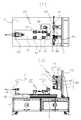
도 1은 본 발명의 바람직한 일실시 예를 도시한 전체구성로서, (가)는 전체구성의 정면도이고, (나)는 전체 구성의 평면도.
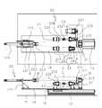
도 2는 본 발명의 바람직한 일실시 예를 도시한 전체구성의 좌측면도.
도 3은 본 발명의 바람직한 일실시 예를 보인 요부의 전체구성을 도시한 정면도.
도 4는 본 발명의 바람직한 일실시 예를 보인 소재작동장치의 전체구성을 도시한 정면도 및 평면도.
도 5는 본 발명의 바람직한 일실시 예를 보인 마스킹 가이드장치의 작동상태를 전체구성으로 도시한 구성상태도.
도 6은 본 발명의 바람직한 일실시 예를 보인 마스킹 풀림장치의 작동상태를 전체구성으로 도시한 구성상태도.
도 7은 본 발명의 바람직한 일실시 예를 보인 소재회전유닛과 밀착롤러 작동장치의 작동상태도로서, (가)는 밀착롤러가 밀착하기 전의 작동상태도 이고, (나)는 밀착롤러가 밀착한 상태의 작동상태도.
도 8은 본 발명의 바람직한 일실시 예를 보인 테이프 작동장치의 요부구성을 도시한 요부구성도.
도 9는 본 발명의 바람직한 일실시 예를 보인 테이프 절단공정의 작동상태도로서, (가)는 테이프 안내장치가 작동한 상태의 작동상태도 이고, (나)는 밀판을 전진시킨 상태의 작동상태도 이며, (다)는 절단날을 전진시킨 상태의 작동상태도.
BRIEF DESCRIPTION OF THE DRAWINGS FIG. 1 is an overall configuration showing a preferred embodiment of the present invention, wherein (A) is a front view of an entire configuration, and (B) is a plan view of an entire configuration;
2 is a left side view of an entire configuration showing a preferred embodiment of the present invention.
3 is a front view showing the entire configuration of a recessed portion showing a preferred embodiment of the present invention.
4 is a front view and a plan view showing the overall configuration of a material operation apparatus showing a preferred embodiment of the present invention.
FIG. 5 is a configuration diagram showing an operating state of a masking guide apparatus as a whole according to a preferred embodiment of the present invention. FIG.
FIG. 6 is a configuration diagram showing an operating state of a masking and unwinding apparatus according to a preferred embodiment of the present invention as a whole. FIG.
Fig. 7 is an operational state diagram of a material rotating unit and a contact roller operating device showing a preferred embodiment of the present invention. Fig. 7 (a) is an operating state before the contact roller is in close contact, Of the operating state.
FIG. 8 is a configuration view showing a main part of a tape operating device according to a preferred embodiment of the present invention. FIG.
FIG. 9 is an operational state diagram of a tape cutting process showing a preferred embodiment of the present invention. FIG. 9 (a) is an operating state of the tape guiding apparatus in an operating state, (C) is an operating state in which the cutting edge is advanced.
이하, 본 발명의 실시 예를 첨부된 도면과 함께 구체적으로 설명하면 다음과 같다. 그리고 공지된 구성 및 그와 관련된 작용은 생략 또는 간단히 설명하였고, 도면에서 각 구성요소 또는 그 구성요소를 이루는 특정 부분의 크기는 설명의 편의 및 명확성을 위하여 과장되거나 생략되거나 또는 개략적으로 도시될 수 있다.Hereinafter, embodiments of the present invention will be described in detail with reference to the accompanying drawings. The known configurations and their associated operations are omitted or briefly described, and the size of each element or a specific portion constituting the element in the drawings may be exaggerated, omitted, or schematically shown for convenience and clarity of description .
도 1과 도 2에 도시된 바와 같이, 본 발명에 따른 원통의 원주방향 테이핑 장치는 상단부에 구성한 베이스(11)의 한쪽 측면 상단부에 베이스(11)와 직각으로 구비한 기준판(12)을 구성한 프레임(10)과;1 and 2, the cylindrical circumferential taping device according to the present invention comprises a
상기 베이스(11) 중심부에 고정하되 이송판(15) 상부에 안착판(14)을 구비한 직교좌표 로봇(13)과, 상기 안착판(14)의 상단 중심부 한쪽 측면에 구성한 소재기준유닛(21)과, 소재기준유닛(21)과 대칭되는 맞은 편에 구성하는 소재고정유닛(22)과, 소재기준유닛(21)과 소재고정유닛(22) 사이의 중심부를 기준으로 대칭으로 구성하는 구동롤러(23)와 연동롤러(24)를 복수로 구성하되 구동롤러(23)를 구동모터(2M)로 구동하도록 구성하는 소재회전유닛(20)를 포함하는 소재작동장치(2)와;A
상기 기준판(12) 상단부 전면에 테이프(T)를 고정하는 테이프클램프(31)와, 인출시킨 테이프(T)를 안내하는 다수의 가이드바(35)로 구성하는 마스킹 가이드장치(30)와;A
마스킹 가이드장치(30)의 하단부에 위치하도록 기준판(12)에서 돌출시키되 상하LM가이드(41)에 고정되어 테이프(T)를 잡는 그리퍼(42)를 풀림실린더(4S)로 상하 이송하도록 하는 마스킹 풀림장치(40)와;The
상기 기준판(12)에서 돌출시켜서 마스킹 풀림장치(40)의 한쪽 측면에 고정한 좌우LM가이드(51)에 체결고정하되 상단부에 절단날(52)을 구비하고 하단부에 밀판(53)을 구비하여 테이프 절단실린더(5S)에 의해 좌우방향으로 이동하도록 구성한 테이프 절단장치(50)와;A
상기 마스킹 풀림장치(40)의 다른 쪽 측면의 기준판(12)에 돌출시킨 안내고정블록(61)에 체결고정한 안내실린더(6S)의 로드(R)에 체결하여, 절단날(52) 끝단 부가 삽입되는 안내홈(62)을 구비한 안내블록(63)이 안내실린더(6S)에 의해 좌우로 이동하도록 구성하는 테이프 안내장치(60)와;Is fastened to a rod (R) of a guide cylinder (6S) fastened and fixed to a guide fixing block (61) protruding from a reference plate (12) on the other side of the masking and unwinding device (40) A tape guide device (60) configured to move the guide block (63) provided with the guide groove (62) inserted therebetween by the guide cylinder (6S) to the left and right;
상기 테이프 안내장치(60)의 하부의 기준판(12)에 돌출시킨 롤러고정블록(73)에 고정한 롤러실린더(7S)의 로드(R)에, 다수의 밀착롤러(72)를 원주방향으로 구성한 롤러유닛(71)을 체결하여 롤러실린더(7S)에 의해 밀착롤러(72)가 좌우로 이동하도록 구성하는 밀착롤러 작동장치(70)를 포함하는 테이프작동장치(1)로 각각 구성한다.A plurality of
우선, 프레임(10)은 상단부에 구성한 베이스(11)의 한쪽 측면 상단부에 베이스(11)와 직각으로 구비한 기준판(12)을 형성한 구성으로 이는 통상의 알루미늄 프로파일로 모서리를 구성하고 각각의 프로파일 사이에 철판으로 테두리를 구성하여 내부에 공간을 형성하여 필요한 전기적 기계적 구성을 구비할 수 있도록 하고 하단부에 안착판이나 롤러를 구성하는 통상의 기계장치를 구성하는 기초구조물로 이에 대한 더 이상의 설명은 생략하기로 한다.First, the
소재작동장치(2) 또한, 상기 베이스(11) 중심부에 고정하되 상부에 구비한 이송판(15) 상단 면에 안착판(14)을 구성한 직교좌표 로봇(13)과, 상기 안착판(14)의 상단 중심부 한쪽 측면에 구성한 소재기준유닛(21)과, 소재기준유닛(21)과 대칭되는 맞은 편에 구성하는 소재고정유닛(22)과, 소재기준유닛(21)과 소재고정유닛(22) 사이의 중심부를 기준으로 대칭으로 구성하는 구동롤러(23)와 연동롤러(24)를 복수로 구성하되, 구동롤러(23)를 구동모터(2M)로 구동하도록 구성하는 소재회전유닛(20)을 포함하는 구성으로, 구동롤러(23)와 연동롤러(24) 상단에 원통형 소재(S)를 안착한 후 고정된 소재기준유닛(21)을 기준으로 작동하는 소재고정유닛(22)을 작동하여 원통형 소재(S)를 고정한 상태에서 원통형 소재(S)의 양쪽 끝단의 위치를 고정한 상태에서 구동모터(2M)를 작동하여 구동롤러(23)가 회전하면서 원통형 소재(S)를 회전하고 연동롤러(24)가 원통형 소재(S)를 동일 중심선상에서 안정적으로 회전하도록 하는 구조로써, 직교좌표 로봇(13)을 가동하여 이송판(15)이 이동하면서 안착판(14)의 위치를 베이스(11) 상부에서 좌우로 이동하면서 소재회전유닛(20) 상부에서 회전하는 원통형 소재(S)의 위치 결정하도록 작동하는 구성임을 알 수 있다.(도 3 참조)The
즉, 안착판(14)의 한쪽 측면 상단부에 구성하는 소재기준유닛(21)은 안착판(14)에 고정하는 기준블록(211)의 상단부에 형성한 기준홀(212)에 베어링(B)으로 체결하는 기준축(213)에서 돌출시킨 기준환(214)의 측면이 원통형 소재(S)의 한쪽 측면이 밀착되도록 구성하고;The
또한, 소재기준유닛(21)과 대칭으로 구성하는 소재고정유닛(22)은 로드(R)가 소재기준유닛(21) 방향으로 유지하는 밀착실린더(22S)를 고정구(221)로 안착판(14)의 다른 쪽 측면에 고정하되 로드(R) 끝단 부에 고정한 소재고정블록(222)의 전면외경에 베어링(B)으로 체결한 밀착환(223)을 구성하되, 소재고정블록(222)의 양측에 가이드축(224)를 고정하여 고정구(221)에 로드(R) 방향으로 슬라이드 되도록 구성하며;The
상기 연동롤러(24)는 안착판(14)의 상단 면에 고정하는 연동블록(241)의 상부에 형성한 연동홀(242)에, 한쪽에 연동롤(243)을 돌출시켜 구비한 연동축(244)을 삽입하여 베어링(B)으로 체결고정하여 연동블록(241)에서 연동롤(243)이 회전하도록 구성하고;The interlocking
구동롤러(23) 또한 안착판(14)의 상단 면에 고정하는 구동블록(231)의 상부에 형성한 구동홀(232)에, 한쪽에 구동롤(233)을 돌출시켜 구비한 구동축(234)을 삽입하여 베어링(B)으로 체결고정하여 구동블록(231)에서 구동롤(233)이 회전하도록 구성한다.(도 4 참조) The
그리고 소재회전유닛(20)은 구동홀(232)에 삽입한 구동축(234)을 구동블록(231) 외부로 돌출시켜서 종동기어(235)를 고정하고, 구동블록(231)의 한쪽에 구동기어(237)를 구비한 구동모터(2M)를 안착판(14)에 고정하여 종동기어(235)와 구동기어(237)를 벨트(236)로 연결구성하여 구동모터(2M)를 작동하여 벨트(236)가 구동축(234)을 회전시켜서 구동롤(233)이 회전하도록 구성하는 것이 바람직하다.The
그뿐만 아니라 구동롤러(23)와 연동롤러(24)의 구동롤(233)과 연동롤(243)이 서로 일정한 거리를 유지하도록 하되 서로 같은 선상에 유지되도록 하여야 하며, 구동롤러(23)와 연동롤러(24)를 복수 또는 다수로 구성할 때에도 각각의 구동롤(233)과 연동롤(243)이 서로 같은 선상을 유지하도록 하여 대칭을 유지하도록 하여야 하며;The driving
이때, 구동롤러(23)를 복수 이상으로 구성할 때에는 서로 인접하는 측에 돌출시킨 연결축(238)에 커플링(239)과 같은 고정구로 연결고정하여 구동모터(2M)에서 발생되는 회전력을 직접적으로 전달받도록 하는 것이 바람직하다.At this time, when constituting a plurality of
상기와 같이 구성된 소재작동장치(2)는 일정한 거리를 유지하는 구동롤러(23)와 연동롤러(24) 사이의 중심부에 테이핑하고자 하는 원통형 소재(S)를 안착한 상태에서 소재고정유닛(22)의 밀착실린더(22S)를 전진시켜서 밀착환(223)이 원통형 소재(S)의 한쪽 끝단 면을 밀어서 다른 쪽 끝단 면이 소재기준유닛(21)의 기준환(214)에 밀착하도록 하여 원통형 소재(S)를 안착고정한 다음 직교좌표 로봇(13)을 작동하여 이송판(15)을 상기 기준판(12) 쪽으로 이송한 다음 구동모터(2M)를 작동하여 소재회전유닛(20)을 통해 구동롤러(23)를 회전시키면 원통형 소재(S)가 구동롤러(23) 반대방향으로 회전하면서 연동롤러(24)를 구동롤러(23)와 동일한 방향으로 회전시키면서 구동롤러(23)와 연동롤러(24) 사이에서 안정적으로 회전하는 구조임을 알 수 있다.The
이때, 원통형 소재(S)의 양쪽 끝단에 밀착된 기준환(214)과 밀착환(223)은 기준블록(211)과 소재고정블록(222)에 각각 견고히 연결된 상태에서도 베어링(B)에 의해 용이하게 회전하는 구조이므로, 원통형 소재(S)가 구동롤(233)과 연동롤(243) 상부에 안착된 상태에서도 동일한 중심에서 동심원을 유지하면서 용이하고 안전하게 회전하도록 하는 효과를 유발하도록 하는 것이다.In this case, the
또한, 테이프작동장치(1)는 마스킹 가이드장치(30)와, 마스킹 풀림장치(40) 및 테이프 절단장치(50), 테이프 안내장치(60), 밀착롤러 작동장치(70)를 각각 구성하되 서로 유기적으로 작동하면서 테이프(T)를 순차적으로 인출하여 원통형 소재(S)의 외경에 감기도록 하는 테이핑 작업을 진행하는 장치로써, 하기에 기술하는 각각의 장치와 작용에 의해 이루어짐을 알 수 있다.The
우선 마스킹 가이드장치(30)는 상기 기준판(12) 상단부 전면에 테이프(T)를 고정하는 테이프클램프(31)와, 인출시킨 테이프(T)를 안내하는 다수의 가이드바(35)로 구성하는 구조로써, 테이프클램프(31)의 끝단 부에 회전롤(32)을 베어링(B)으로 체결하여 일정한 회전압력이 유지하도록 구성하고, 회전롤(32)에 테이프(T)를 장착하여 테이프(T)의 끝단을 인출하여 다수의 가이드바(35)에 순차적으로 테이프(T)가 걸리도록 구성하되 가이드바(35)의 외경에 테이프(T)가 밀착하여 미끄럼 회전하는 회전부시(33)를 구성하여 테이프(T)의 밀착 면이 회전부시(33)의 외경에 밀착하여도 용이하게 풀림 되도록 구성하여 회전롤(32)에서 장착 풀림 되는 테이프(T)가 다수의 가이드바(35)를 거치도록 하여 풀림 되는 테이프(T)에 일정한 텐션을 유지하도록 하면서 여유있는 풀림 상태를 유지하도록 하는 구성임을 알 수 있다. (도 5 참조)The masking
마스킹 풀림장치(40)는 마스킹 가이드장치(30)의 하단부에 위치하도록 기준판(12)에서 돌출시키되 상하LM가이드(41)에 고정되어 테이프(T)를 잡는 그리퍼(42)를 풀림실린더(4S)로 상하 이송하도록 하는 구조로써, 상기 마스킹 가이드장치(30)를 통해 인출된 테이프(T)의 끝단 부가 그리퍼(42) 하단으로 둘출되도록 한 상태에서 그리퍼(42)를 클램핑하여 풀림실린더(4S)를 전진시켜서 그리퍼(42)를 하강하면, 테이프(T)가 회전롤(32)에서 풀리면서 다수의 가이드바(35)를 거치면서 하부로 이동하도록 하는 구조이다.The masking and unwinding
상기 마스킹 풀림장치(40)는 기준판(12)에서 풀림블록(43)을 돌출시켜서 전면에 풀림고정판(44)을 구성하고 풀림고정판(44)의 상부 끝단에 풀림실린더(4S)를 체결 고정하며, 전면 중심부에 상하LM가이드(41)의 LM레일(4L)을 고정하고 LM블록(4B)에 풀림실린더(4S) 로드(R) 끝단에 체결된 풀림이송판(45)을 고정하며, 풀림이송판(45) 전면에 고정한 그립실린더(42S)에 그리퍼(42)를 장착하여 구성하는 것이 바람직하다.The masking and unwinding
이에 그립실린더(42S)를 해지하여 그리퍼(42)가 일정거리를 유지한 상태에서 상기 마스킹 가이드장치(30)를 통해 인출된 테이프(T)의 끝단 부가 그리퍼(42) 사이의 중심으로 하강하여 그리퍼(42) 하단으로 일정거리만큼 내려가서 하부로 둘출되도록 한 상태에서 그립실린더(42S)를 작동하여 그리퍼(42)를 클램핑한 다음 풀림실린더(4S)의 로드(R)를 하강하면 그리퍼(42)를 고정하고 있는 풀림이송판(45)이 하강하게 되므로 그립실린더(42S)로 인해 테이프(T)를 클램핑한 그리퍼(42)가 하강하면서 테이프(T) 끝단 부를 하부로 하강하면서 마스킹 가이드장치(30)가 작동하면서 테이프(T) 풀림작업을 동시에 진행하는 구조이다.(도 6참조)The end of the tape T pulled out through the masking
밀착롤러 작동장치(70)는 상기 테이프 안내장치(60)의 하부에 돌출시킨 롤러고정블록(79)에 고정한 롤러실린더(7S)의 로드(R)에, 다수의 밀착롤러(72)를 원주방향으로 구성한 롤러유닛(71)을 체결하여 롤러실린더(7S)에 의해 밀착롤러(72)가 좌우로 이동하도록 구성하는 구조로써, 상기 마스킹 풀림장치(40)를 통해 하강한 테이프(T)의 끝단 부가 소재작동장치(2)의 구동롤러(23)와 연동롤러(24) 사이의 중심 상단부에 안착한 원통형 소재(S)의 외경 중심선 하단부까지 이동하면 롤러실린더(7S)의 로드(R)를 전진시켜서 원통형 소재(S)의 중심과 동일선상에 구성하는 밀착롤러(72)가 원통형 소재(S) 쪽으로 밀착하도록 하여 밀착롤러(72)와 원통형 소재(S)의 사이에 유지하는 테이프(T)를 원통형 소재(S)에 밀착시키는 구조이다. (도 7 참조)The tightening
이때, 롤러실린더(7S)의 로드(R)에 고정하는 롤러유닛(71)은 한쪽을 로드(R)에 체결고정하는 롤러이송블록(73)에 연결핀(74)과 탄성체(ST)로 구성하여 일정거리만큼 탄성력으로 이동하고 복귀할 수 있도록 고정한 롤러고정구(76)의 다른 쪽에 원주방향으로 다수의 밀착롤러(72)를 장착구성한 롤러회전구(75)를 롤러기준축(77) 중심으로 회전하도록 하되 별도의 회전고정구(78)로 롤러회전구(75)의 고정이 가능토록 구성하며, 롤러회전구(75)에 구성하는 각각의 밀착롤러(72)의 외경이 서로 다르게 구성하는 구조이다.At this time, the
이는 소재작동장치(2)에 안착하는 원통형 소재(S)의 외경에 따라 서로 다른 밀착롤러(72)를 회전하여 이동시켜서 원통형 소재(S)의 외경 중심에 밀착하도록 하여 일정한 행정거리를 유지하는 롤러실린더(7S)의 행정거리의 한계를 극복할 수 있도록 하며, 탄성체(ST)의 탄성력으로 원통형 소재(S)에 밀착하는 밀착롤러(72)의 밀착력을 조절할 수 있도록 하는 구조임을 알 수 있다.This makes it possible to move the
뿐만 아니라, 테이프 절단장치(50)는 기준판(12)에서 돌출시켜서 마스킹 풀림장치(40)의 한쪽 측면에 고정한 좌우LM가이드(51)에 체결고정하되 상단부에 절단날(52)을 구비하고 하단부에 밀판(53)을 구비하여 테이프 절단실린더(5S)에 의해 좌우방향으로 이동하도록 구성함으로써, 원통형 소재(S)의 외경에 테이핑 작업을 완료한 상태에서 마스킹 가이드장치(30)에서 인출된 테이프(T)를 절단하기 위해 테이프 절단실린더(5S)의 로드(R)를 전진시켜서 절단날(52)이 테이프(T)를 절단하도록 하는 구조임을 알 수 있다.The
즉, 기준판(12)에서 돌출시킨 좌우고정편(54) 상단부에 좌우LM가이드(51)를 구성하고, 좌우고정편(54)의 측면 상단부에 로드(R)가 좌우LM가이드(51) 상부로 구동되도록 테이프 절단실린더(5S)를 장착고정하며, LM블록(51B) 상부에 고정한 좌우이송블록(55)에 로드(R)를 체결하되, 좌우이송블록(55)의 상단부에 절단날실린더(52S)를 고정하여 로드(R)에 고정한 절단날기준편(521)을 구성하여, 한쪽에 절단날(52)을 고정하는 절단날고정구(522)의 다른 쪽에 외경으로 탄성체(ST)를 구비한 절단날탄성봉(523)으로 연결 구성하여 절단날고정구(522)와 절단날기준편(521)에 탄성체(ST)로 인해 일정한 탄성력을 유지하도록 하고, 좌우이송블록(55)의 전면에 밀판실린더(53S)를 고정하여 밀판(53)을 고정하는 밀판고정구(531)를 밀판실린더(53S)의 로드(R)에 장착고정하여 구성하는 것이 바람직한 구성이다. (도 8과 도 9 참조)That is, the left and right LM guides 51 are formed at the upper ends of the left and right fixing
그리고 테이프 안내장치(60)는 상기 마스킹 풀림장치(40)의 다른 쪽 측면의 기준판(12)에 돌출시킨 안내고정블록(61)에 체결고정한 안내실린더(6S)의 로드(R)에 체결하여, 절단날(52) 끝단 부가 삽입되는 안내홈(62)을 구비한 안내블록(63)이 안내실린더(6S)에 의해 좌우로 이동하도록 하는 구성으로서, 안내실린더(6S)의 로드(R)를 전진하여 안내블록(63) 끝단 면이 테이프(T)에 밀착되도록 한 상태에서 절단날(52)이 전진하여 테이프(T)를 절단함과 동시에 안내홈(62)으로 삽입하도록 하여 절단날(52)의 테이프(T) 절단을 정밀하고 용이하게 하도록 하는 구조임을 알 수 있다.The
이상 상기와 같이 구성한 원통의 원주방향 테이핑 장치를 통해 원통형 소재(S)의 외경에 필요한 테이프(T)를 테이핑하는 테이핑 작업이 신속하고 정밀하면서도 일정하게 이루어지도록 하는 것으로 우선, 상기 소재회전유닛(20)의 구동롤러(23)와 연동롤러(24) 상부에 마스킹하고자 하는 원통형 소재(S)를 안착한 다음 밀착실린더(22S)를 전진시켜서 밀착환(223)이 원통형 소재(S)의 한쪽 끝단 면을 밀어서 다른 쪽 끝단 면이 소재기준유닛(21)의 기준환(214)에 밀착하도록 하여 원통형 소재(S)를 안착고정한 다음 직교좌표 로봇(13)을 작동하여 이송판(15)을 상기 기준판(12) 쪽으로 이송하여 원통형 소재(S)의 테이핑하고자 하는 위치를 결정한 한 다음 마스킹 풀림장치(40)의 그리퍼(42)로 테이프(T) 끝단 부가 돌출되도록 클램핑한 다음 풀림실린더(4S)의 로드(R)를 하강하여 테이프(T) 끝단 부가 하부로 하강하여 소재작동장치(2)에 안착한 원통형 소재(S)의 외경 중심부의 한쪽 측면 하부로 이동하게 된다.The taping operation for taping the tape T required for the outer diameter of the cylindrical workpiece S through the cylindrical circumferential taping device constructed as described above can be performed quickly, precisely and constantly. First, the
이때, 그리퍼(42)는 원통형 소재(S)의 중심부 상부에 정지한 상태를 유지하고 테이프(T)의 끝단 부만 원통형 소재(S)의 중심부 하부로 내려온 상태를 유지하도록 한 다음 밀착롤러 작동장치(70)의 롤러실린더(7S)를 작동하여 밀착롤러(72)가 테이프(T) 한쪽면에 밀착한 상태로 원통형 소재(S) 쪽으로 밀어서 원통형 소재(S)와 밀착롤러(72) 사이에 테이프(T)가 유지한 상태로 원통형 소재(S)에 밀착롤러(72)가 밀착되도록 하되 테이프(T)의 밀착 면이 원통형 소재(S)의 외경 면에 유지하도록 가이드 하는 것이 바람직할 것이다.At this time, the
상기와 같이 테이프(T)가 원통형 소재(S)의 한쪽 외경에 밀착한 상태에서 그리퍼(42)를 개방하여 테이프(T)를 언클램핑한 상태에서 풀림실린더(4S)의 로드(R)를 후진하여 그리퍼(42)를 상승시킨 다음, 소재작동장치(2)의 구동모터(2M)를 작동하여 구동롤러(23)를 회전시키면 구동롤러(23) 상부에 안착한 원통형 소재(S)가 구동롤러(23)의 회전방향 반대방향으로 회전하면서 연동롤러(24)가 구동롤러(23)와 같은 방향으로 회전하게 되므로 연동롤러(24)와 구동롤러(23) 상이의 상부에 안착된 원통형 소재(S)가 연동롤러(24)와 구동롤러(23)의 반대방향으로 안정적으로 회전하게 되므로 밀착롤러(72)에 의해 원통형 소재(S)의 외경에 밀착된 상태의 테이프(T)가 원통형 소재(S)가 회전하는 방향으로 따라 회전하는 구조이므로, 테이프(T)가 테이프클팸프(31)에서 인출되어 가이드바(35)를 거쳐서 원통형 소재(S)의 외경에 필요한 양의 테이프(T)를 테이핑할 수 있다.The rod R of the
상기와 같이 테이핑 작업이 완료되면 밀착롤러(72) 밀착한 상태에서 구동모터(2M)를 정지하여 구동롤러(23)의 회전을 정지시킨 후 그리퍼(42)를 클램핑하여, 밀착롤러(72)와 그리퍼(42)에 의해 테이프(T)가 고정된 상태에서 상기 테이프 절단장치(50)의 테이프 절단실린더(5S)를 전진시켜서 절단날(52)과 밀판(53)이 테이프(T) 근처에 접근하도록 한 다음 상기의 테이프 안내장치(60)의 안내실린더(6S)를 전진하여 안내블록(63)이 테이프(T)에 근접 또는 밀착하도록 한다.When the taping operation is completed as described above, the
이후 먼저 하부에 위치한 밀판실린더(53S)를 전진하여 밀판(53)이 테이프(T)를 안내블록(63) 쪽으로 밀어내어 밀판(53)에 밀린 테이프(T) 부분이 안내블록(63)의 끝 단면보다 안내블록(63) 쪽으로 이동하여 테이프(T)가 팽팽하게 유지하도록 한 다음 절단날실린더(52S)를 전진시켜서 테이프(T)를 절단한 절단날(52)이 안내블록(63)의 안내홈(62) 내부까지 전진하도록 하여 테이프(T)의 절단이 절단날(52)에 의해 완벽하게 절단할 수 있도록 하는 절단작업을 진행한다.The
상기와 같이 절단 날(52)로 테이프(T)를 절단한 절단작업이 완료되면 절단작업의 진행순서와 역순으로 절단날(52)과 밀판(53)을 순차적으로 후진하고, 안내블록(63)과 좌우이송블록(55)을 후진시킨 다음 다시 구동모터(2M)를 작동하여 구동롤러(23)가 회전하면서 원통형 소재(S)가 회전시켜서 절단날(52)에 의해 절단된 테이프(T)의 절단부위가 원통형 소재(S)의 외경에 마저 감기면서 테이핑 되도록 하여 테이핑 작업을 완료한 후 밀착롤러 작동장치(70)의 롤러실린더(7S)를 후진하여 밀착롤러(72)가 원통형 소재(S)에서 떨어져서 일정거리를 유지하도록 하여 테이핑 작업을 완료하는 것이 바람직할 것이다.When the cutting operation of cutting the tape T with the
상기와 같이 구성되어 작용하는 원통의 원주방향 테이핑 장치는 표면에 테이핑을 할 원통형 소재를 소재작동장치(2)에 평행하게 안착하여 원주방향으로 회전시키면서 테이프를 회전하는 원통형 소재의 외경에 밀착하여 회전하는 원통형 소재의 외경에 원주방향으로 테이핑한 다음 테이프 절단장치(50)와 테이프 안내장치(60)로 테이프(T)를 절단하는 테이핑 작업을 완료할 수 있도록 하므로 중량뿐만 아니라 길이가 긴 원통형 소재의 외경에 원주방향으로 테이핑이 용이하도록 할 뿐만 아니라 원통형 소재(S)의 원둘레와 테이핑할 테이프(T)의 넓이를 용이하게 교체하여 변형할 수 있도록 하여 하나의 테이핑 장치로 다양한 사이즈의 원통형 소재에 다양한 색상과 형태의 테이프를 신속하고 용이하면서도 안정적으로 테이핑할 수 있음은 물론 테이핑의 품질이 균일하여 불량을 방지할 수 있는 생산성이 우수하고 안전하면서도 우수한 품질의 테이핑 작업이 쉬워지도록 하는 효과가 있는 발명으로 본 발명을 기재된 구체적인 예에 대해서만 상세히 설명되었지만, 본 발명의 사상과 범위 내에서 다양하게 변경 또는 변형이 이루어질 수 있음은 본 발명이 속하는 기술분야의 당업자에게는 자명한 것이며, 따라서 그러한 변경 또는 변형은 첨부된 특허등록청구범위에 속한다 해야 할 것이다.The cylindrical circumferential taping device constructed as described above has a cylindrical material which is to be taped on the surface and which is placed parallel to the
1: 테이프 장착장치2: 소재 작동장치
10: 프레임
11: 베이스12: 기준판
13: 직교좌표 로봇14: 안착판
15: 이송판
20: 소재회전유닛
21: 소재기준유닛
211: 기준블록212: 기준홀
213: 기준축214: 기준환
22: 소재고정유닛
221: 고정구222: 소재고정블록
223: 밀착환224: 가이드축
23: 구동롤러
231: 구동블록232: 구동홀
233: 구동롤234: 구동축
235: 종동기어236:벨트
237: 구동기어238: 연결축
239: 커플링
24: 연동롤러
241: 연동블록242: 연동홀
243: 연동롤244: 연동축
2M: 구동모터
30: 마스킹 가이드장치
31: 케이프클램프32: 회전롤
33: 회전부시35: 가이드바
40: 마스킹 풀림장치
41: 상하LM가이드42: 그리퍼
43: 풀림블록44: 풀림고정판
45: 풀림이송판4S: 풀림실린더
50: 테이프 절단장치
51: 좌우LM가이드52: 절단날
521: 절단날기준편522: 절단날고정구
523: 절단날탄성봉52S: 절단날실린더
53: 밀판531: 밀판고정구
54: 좌우고정판55: 좌우이송블록
60: 테이프 안내장치
61: 안내고정블록62: 안내홈
63: 안내블록6S: 안내실린더
70: 밀착롤러 작동장치
71: 롤러유닛72: 밀착롤러
73: 롤러이송블록74: 연결핀
75: 롤러회전구76: 롤러고정구
77: 롤러기준축78: 회전고정구
79: 롤러고정블록7S: 롤러실린더
R: 로드S: 원통형 소재
T: 테이프TS: 탄성체1: tape loading device 2: material operation device
10: frame
11: base 12: reference plate
13: Cartesian coordinate robot 14: seating plate
15:
20: Material rotation unit
21: Material reference unit
211: Reference block 212: Reference hole
213: reference axis 214: reference circle
22: Material fixing unit
221: fixture 222: material fixing block
223: contact ring 224: guide shaft
23: drive roller
231: driving block 232: driving hole
233: drive roll 234: drive shaft
235: driven gear 236: belt
237: driving gear 238: connecting shaft
239: Coupling
24: Interlocking roller
241: Interlocking block 242: Interlocking hole
243: Interlocking roll 244: Interlocking shaft
2M: drive motor
30: masking guide device
31: Cape clamp 32: Rotary roll
33: rotating bush 35: guide bar
40: Masking release device
41: upper and lower LM guide 42: gripper
43: release block 44: release release plate
45:
50: tape cutting device
51: left and right LM guide 52: cutting blade
521: Cutting edge reference piece 522: Cutting edge fixture
523: cutting blade
53: Plate 531: Plate fastener
54: left and right fixing plate 55: left and right conveying block
60: tape guide device
61: guide fixing block 62: guide groove
63:
70: Adhesive roller operating device
71: roller unit 72: close roller
73: roller transport block 74: connecting pin
75: roller rotation hole 76: roller fixing hole
77: roller reference shaft 78: rotating fixture
79:
R: Rod S: Cylindrical material
T: tape TS: elastic body
Claims (5)
Translated fromKorean상기 베이스(11) 중심부에 고정하되 이송판(15) 상부에 안착판(14)을 구비한 직교좌표 로봇(13)과, 상기 안착판(14)의 상단 중심부 한쪽 측면에 구성한 소재기준유닛(21)과, 소재기준유닛과 대칭되는 맞은 편에 구성하는 소재고정유닛(22)과, 소재기준유닛(21)과 소재고정유닛(22) 사이의 중심부를 기준으로 대칭으로 구성하는 구동롤러(23)와 연동롤러(24)를 복수로 구성하되 구동롤러(23)를 구동모터(2M)로 구동하도록 구성하는 소재회전유닛(20)를 포함하는 소재작동장치(2)와;
상기 기준판(12) 상단부 전면에 테이프(T)를 고정하는 테이프클팸프(31)와, 인출시킨 테이프(T)를 안내하는 다수의 가이드바(35)로 구성하는 마스킹 가이드장치(30)와;
마스킹 가이드장치(30)의 하단부에 위치하도록 기준판(12)에서 돌출시키되 상하LM가이드(41)에 고정되어 테이프(T)를 잡는 그리퍼(42)를 풀림실린더(4S)로 상하 이송하도록 하는 마스킹 풀림장치(40)와;
상기 기준판(12)에서 돌출시켜서 마스킹 풀림장치(40)의 한쪽 측면에 고정한 좌우LM가이드(51)에 체결고정하되 상단부에 절단날(52)을 구비하고 하단부에 밀판(53)을 구비하여 테이프 절단실린더(5S)에 의해 좌우방향으로 이동하도록 구성한 테이프 절단장치(50)와;
상기 마스킹 풀림장치(40)의 다른 쪽 측면에 돌출시킨 안내고정블록(61)에 체결고정한 안내실린더(6S)의 로드(R)에 체결하여, 절단날(52) 끝단 부가 삽입되는 안내홈(62)을 구비한 안내블록(63)이 안내실린더(6S)에 의해 좌우로 이동하도록 구성하는 테이프 안내장치(60)와;
상기 테이프 안내장치(60)의 하부에 돌출시킨 롤러고정블록(73)에 고정한 롤러실린더(7S)의 로드(R)에, 다수의 밀착롤러(72)를 원주방향으로 구성한 롤러유닛(71)을 체결하여 롤러실린더(7S)에 의해 밀착롤러(72)가 좌우로 이동하도록 구성하는 밀착롤러 작동장치(70)를 각각 포함하여 구성하는 것을 특징으로 하는 원통의 원주방향 테이핑 장치.
A frame 10 constituting a reference plate 12 provided at an upper end portion of one side of a base 11 formed at an upper end and at a right angle to the base 11;
A rectangular coordinate robot 13 which is fixed to the center of the base 11 and has a seating plate 14 at the upper part of the conveying plate 15 and a material reference unit 21 which is formed at one side of the upper center of the seating plate 14 And a driving roller 23 which is symmetrically arranged with respect to a center portion between the workpiece reference unit 21 and the workpiece fixing unit 22, And a work rotating unit (20) configured to drive the drive roller (23) by a drive motor (2M), the work rotating unit (20) comprising a plurality of interlocking rollers (24)
A mask clamping device 30 comprising a tape clamp 31 for fixing the tape T on the entire upper surface of the upper end of the reference plate 12 and a plurality of guide bars 35 for guiding the pulled tape T, ;
The masking guide device 30 is provided at the lower end of the reference plate 12 and is fixed to the upper and lower LM guides 41 so that the gripper 42 holding the tape T is transported up and down by the unloading cylinder 4S. A releasing device 40;
A cutting blade 52 is provided at an upper end of the LM guide 51 and a plate 53 is fixed to the left and right LM guides 51 fixed to one side of the masking and unwinding device 40 by protruding from the reference plate 12, A tape cutting device (50) configured to move in the lateral direction by the cutting cylinder (5S);
Is fastened to a rod (R) of a guide cylinder (6S) fastened and fixed to a guide fixing block (61) protruding from the other side surface of the masking and unwinding device (40), and a guide groove And a guiding block (63) provided with a guiding cylinder (6S) for moving the guiding block (63) to the left and right by the guiding cylinder (6S);
A roller unit 71 constituted by a plurality of tight contact rollers 72 in the circumferential direction is attached to a rod R of a roller cylinder 7S fixed to a roller fixing block 73 projected to the lower portion of the tape guiding apparatus 60 And an urging roller actuating device (70) for urging the roller (7S) to move the urging roller (72) to the left and right, respectively.
상기 소재회전유닛(20)은 안착판(14)에 고정하는 기준블록(211)의 상단부에 형성한 기준홀(212)에 베어링(B)으로 체결하는 기준축(213)에서 돌출시킨 기준환(214)의 측면이 원통형 소재(S)의 한쪽 측면이 밀착되도록 구성하는 소재기준 유닛(21)과;
로드(R)가 소재기준유닛(21) 방향으로 유지하는 밀착실린더(22S)를 고정구(221)로 안착판(14)의 다른 쪽 측면에 고정하되 로드(R) 끝단 부에 고정한 소재고정블록(222)의 전면외경에 베어링(B)으로 체결한 밀착환(223)을 구성하되, 소재고정블록(222)의 양측에 가이드축(224)를 고정하여 고정구(221)에 로드(R) 방향으로 슬라이드 되도록 구성하되 상기 소재기준유닛(21)과 대칭으로 구성하는 소재고정유닛(22)과;
안착판(14)의 상단 면에 고정하는 연동블록(241)의 상부에 형성한 연동홀(242)에, 한쪽에 연동롤(243)을 돌출시켜 구비한 연동축(244)을 삽입하여 베어링(B)으로 체결고정하여 연동블록(241)에서 연동롤(243)이 회전하도록 구성하는 연동롤러(24)과;
안착판(14)의 상단 면에 고정하는 구동블록(231)의 상부에 형성한 구동홀(232)에, 한쪽에 구동롤(233)을 돌출시켜 구비한 구동축(234)을 삽입하여 베어링(B)으로 체결고정하여 구동블록(231)에서 구동롤(233)이 회전하도록 구성 구동롤러(23)를 각각 포함하는 것을 특징으로 하는 원통의 원주방향 테이핑 장치.The method of claim 1, further comprising:
The work rotating unit 20 includes a reference shaft 212 protruding from a reference shaft 213 which is fastened with a bearing B to a reference hole 212 formed at an upper end of a reference block 211 fixed to a seating plate 14, 214) is in close contact with one side surface of the cylindrical material (S);
A tightening cylinder 22S holding the rod R in the direction of the workpiece reference unit 21 is fixed to the other side surface of the seating plate 14 with the fixing tool 221 and fixed to the end of the rod R And a guide ring 224 is fixed to both sides of the work fixing block 222 so that the fixing ring 221 is fixed to the fixing ring 221 in the direction of the rod R A work fixing unit (22) configured to be slidable and configured to be symmetrical with the work reference unit (21);
An interlocking shaft 244 having an interlocking roll 243 protruded on one side is inserted into the interlocking hole 242 formed in the upper portion of the interlocking block 241 fixed to the upper surface of the seat plate 14, B), so that the interlocking roll 243 rotates in the interlocking block 241;
A driving shaft 234 having a driving roll 233 protruded on one side is inserted into a driving hole 232 formed on an upper portion of a driving block 231 fixed to the upper surface of the seating plate 14, (231) so that the drive roll (233) rotates in the drive block (231).
상기 마스킹 풀림장치(40)는 기준판(12)에서 풀림블록(43)을 돌출시켜서 전면에 풀림고정판(44)을 구성하고 풀림고정판(44)의 상부 끝단에 풀림실린더(4S)를 체결 고정하며, 전면 중심부에 상하LM가이드(41)의 LM레일(4L)를 고정하고 LM블록(4B)에 풀림실린더(4S) 로드(R) 끝단에 체결된 풀림이송판(45)을 고정하며, 풀림이송판(45) 전면에 고정한 그립실린더(42S)에 그리퍼(42)를 장착하여 구성하는 것을 특징으로 하는 원통의 원주방향 테이핑 장치.The method of claim 1,
The masking and unwinding device 40 is configured such that the release block 43 is protruded from the reference plate 12 to constitute a release fixture plate 44 on the front surface thereof and a release cylinder 4S is fastened and fixed to the upper end of the release fixture plate 44 The LM rail 4L of the upper and lower LM guide 41 is fixed to the front center portion and the loosening plate 45 fastened to the end of the rod 4R of the loom 4S is fixed to the LM block 4B, And a gripper (42) is mounted on a grip cylinder (42S) fixed to the front face of the swinging plate (45).
상기 테이프 절단장치(50)는 기준판(12)에서 돌출시킨 좌우고정편(54) 상단부에 좌우LM가이드(51)를 구성하고, 좌우고정편(54)의 측면 상단부에 로드(R)가 좌우LM가이드(51) 상부로 구동되도록 테이프 절단실린더(5S)를 장착고정하며, LM블록(51B) 상부에 고정한 좌우이송블록(55)에 로드(R)를 체결하되, 좌우이송블록(55)의 상단부에 절단날실린더(52S)를 고정하여 로드(R)에 고정한 절단날기준편(521)을 구성하여, 한쪽에 절단날(52)를 고정하는 절단날고정구(522)의 다른 쪽에 외경으로 탄성체(ST)를 구비한 절단날탄성봉(523)으로 연결 구성하여 절단날고정구(522)와 절단날기준편(521)에 탄성체(ST)로 인해 일정한 탄성력을 유지하도록 하고, 좌우이송블록(55)의 전면에 밀판실린더(53S)를 고정하여 밀판(53)을 고정하는 밀판고정구(531)를 밀판실린더(53S)의 로드(R)에 장착고정하여 구성하는 것을 특징으로 하는 원통의 원주방향 테이핑 장치.
The method of claim 1,
The tape cutting apparatus 50 constitutes a left and right LM guide 51 at the upper end of the left and right fixing pieces 54 protruded from the reference plate 12 and the left and right LM guides 51, The tape cutting cylinder 5S is mounted and fixed to be driven to the upper side of the LM guide 51 and the rod R is fastened to the left and right transport block 55 fixed to the upper portion of the LM block 51B, The cutting edge cylinder 52S is fixed to the upper end to form the cutting edge reference piece 521 fixed to the rod R and the other end of the cutting edge fixture 522 for fixing the cutting edge 52 to one side has an outer diameter, Blade fixing bar 522 and the cutting edge reference piece 521 to maintain a certain elastic force due to the elastic body ST while the left and right feed blocks 55 The plate plate cylinder 53S is fixed to the front of the plate cylinder 53S and the plate plate fixture 531 for fixing the plate 53 is fixed to the rod R of the plate cylinder 53S Constructed by circumferentially taping device of the cylinder, characterized in that a.
상기 롤러유닛(71)은 한쪽을 로드(R)에 체결고정하는 롤러이송블록(73)에 연결핀(74)과 탄성체(ST)로 구성하여 일정거리만큼 탄성력으로 이동하고 복귀할 수 있도록 고정한 롤러고정구(76)의 다른 쪽에 원주방향으로 다수의 밀착롤러(72)를 장착구성한 롤러회전구(75)를 롤러기준축(77) 중심으로 회전하도록 하되 별도의 회전고정구(78)로 롤러회전구(75)의 고정이 가능토록 구성하는 것을 특징으로 하는 원통의 원주방향 테이핑 장치.The method of claim 1,
The roller unit 71 is constituted by a connecting pin 74 and an elastic body ST in a roller conveying block 73 for fastening one end to the rod R, A roller rotation shaft 75 having a plurality of tightening rollers 72 mounted in the circumferential direction on the other side of the fixture 76 is rotated around the roller reference shaft 77 while a roller rotation shaft 75) in the circumferential direction of the cylinder.
Priority Applications (1)
| Application Number | Priority Date | Filing Date | Title |
|---|---|---|---|
| KR1020170171548AKR101952653B1 (en) | 2017-12-13 | 2017-12-13 | Cylindrical direction taping |
Applications Claiming Priority (1)
| Application Number | Priority Date | Filing Date | Title |
|---|---|---|---|
| KR1020170171548AKR101952653B1 (en) | 2017-12-13 | 2017-12-13 | Cylindrical direction taping |
Publications (1)
| Publication Number | Publication Date |
|---|---|
| KR101952653B1true KR101952653B1 (en) | 2019-02-27 |
Family
ID=65560612
Family Applications (1)
| Application Number | Title | Priority Date | Filing Date |
|---|---|---|---|
| KR1020170171548AActiveKR101952653B1 (en) | 2017-12-13 | 2017-12-13 | Cylindrical direction taping |
Country Status (1)
| Country | Link |
|---|---|
| KR (1) | KR101952653B1 (en) |
Cited By (1)
| Publication number | Priority date | Publication date | Assignee | Title |
|---|---|---|---|---|
| CN110240024A (en)* | 2019-05-30 | 2019-09-17 | 四川中物技术股份有限公司威海分公司 | Kinking process automation equipment for fishing rod production |
Citations (8)
| Publication number | Priority date | Publication date | Assignee | Title |
|---|---|---|---|---|
| US4381960A (en)* | 1981-12-28 | 1983-05-03 | United Technologies Corporation | Method of manufacturing a filament wound article |
| JPH10194606A (en)* | 1996-11-11 | 1998-07-28 | Yaskawa Electric Corp | Method and apparatus for manufacturing tape wound yarn bundle |
| KR200291056Y1 (en) | 2002-07-18 | 2002-10-04 | 김기용 | Tape taping apparatus for fishing rod |
| KR100833173B1 (en) | 2006-09-19 | 2008-05-28 | 주식회사 세명기업 | Taping pressure mechanism driving device of automotive rubber hose |
| KR101142491B1 (en) | 2004-12-24 | 2012-05-15 | 주식회사 포스코 | A taping apparatus for tape machine |
| JP2013079145A (en)* | 2011-09-30 | 2013-05-02 | Fujiko Co Ltd | Method for sticking masking tape and device for sticking the same |
| KR101289953B1 (en)* | 2013-04-02 | 2013-07-26 | 문정환 | Adhesive tape cutting and winding apparatus |
| KR20150137022A (en)* | 2014-05-28 | 2015-12-08 | 가부시키가이샤 에바라 세이사꾸쇼 | Tape sticking apparatus and tape sticking method |
- 2017
- 2017-12-13KRKR1020170171548Apatent/KR101952653B1/enactiveActive
Patent Citations (8)
| Publication number | Priority date | Publication date | Assignee | Title |
|---|---|---|---|---|
| US4381960A (en)* | 1981-12-28 | 1983-05-03 | United Technologies Corporation | Method of manufacturing a filament wound article |
| JPH10194606A (en)* | 1996-11-11 | 1998-07-28 | Yaskawa Electric Corp | Method and apparatus for manufacturing tape wound yarn bundle |
| KR200291056Y1 (en) | 2002-07-18 | 2002-10-04 | 김기용 | Tape taping apparatus for fishing rod |
| KR101142491B1 (en) | 2004-12-24 | 2012-05-15 | 주식회사 포스코 | A taping apparatus for tape machine |
| KR100833173B1 (en) | 2006-09-19 | 2008-05-28 | 주식회사 세명기업 | Taping pressure mechanism driving device of automotive rubber hose |
| JP2013079145A (en)* | 2011-09-30 | 2013-05-02 | Fujiko Co Ltd | Method for sticking masking tape and device for sticking the same |
| KR101289953B1 (en)* | 2013-04-02 | 2013-07-26 | 문정환 | Adhesive tape cutting and winding apparatus |
| KR20150137022A (en)* | 2014-05-28 | 2015-12-08 | 가부시키가이샤 에바라 세이사꾸쇼 | Tape sticking apparatus and tape sticking method |
Cited By (1)
| Publication number | Priority date | Publication date | Assignee | Title |
|---|---|---|---|---|
| CN110240024A (en)* | 2019-05-30 | 2019-09-17 | 四川中物技术股份有限公司威海分公司 | Kinking process automation equipment for fishing rod production |
Similar Documents
| Publication | Publication Date | Title |
|---|---|---|
| CN107187922B (en) | Method and equipment for slitting adhesive tape parent roll | |
| KR101372774B1 (en) | Apparatus for automatic feeding and attching sponge tape | |
| JP2015160285A (en) | O-ring mounting apparatus and method | |
| KR101952653B1 (en) | Cylindrical direction taping | |
| CN111312610A (en) | Wafer film sticking machine, film pulling device and wafer film sticking method | |
| CN209582130U (en) | A multi-station labeling equipment based on manipulator | |
| CN207158458U (en) | A kind of cutting apparatus of adhesive tape parent roll | |
| WO2018201526A1 (en) | Labeling machine for lower surface | |
| WO2018201527A1 (en) | Positioning and gripping device of labeling machine for lower surface | |
| KR102513895B1 (en) | Automatic cutting device and winding device of continuous paper cutter | |
| CN114193411B (en) | A workbench with automatic clamping function | |
| CN109665134B (en) | Automatic continuous film wrapping equipment | |
| CN109411831B (en) | Rubberizing device | |
| JP4974094B1 (en) | Masking tape application method and application device | |
| CN112676833A (en) | Detection device and cantilever production line | |
| CN116994997A (en) | Two-dimensional material transfer device and transfer method thereof | |
| CN108832440B (en) | Automatic wire harness loop system of full-automatic wire harness machining and assembling equipment | |
| CN114435660B (en) | Automatic arrangement packagine machine with trade mark sign cuts apart | |
| CN205011146U (en) | Around rolling up layer that main shaft be hollow shaft around machine and around a roll main shaft | |
| CN216966856U (en) | Package cotton equipment in middle of atomizing core secondary | |
| CN111731566B (en) | Automatic binding equipment | |
| CN115973834A (en) | Automatic roll changing mechanism and gluing device | |
| CN210417072U (en) | Automatic change biax winding equipment for packing | |
| WO2018110227A1 (en) | Tape winding device | |
| CN210417081U (en) | A double-shaft winding and rolling device |
Legal Events
| Date | Code | Title | Description |
|---|---|---|---|
| PA0109 | Patent application | Patent event code:PA01091R01D Comment text:Patent Application Patent event date:20171213 | |
| PA0201 | Request for examination | ||
| E701 | Decision to grant or registration of patent right | ||
| PE0701 | Decision of registration | Patent event code:PE07011S01D Comment text:Decision to Grant Registration Patent event date:20190218 | |
| GRNT | Written decision to grant | ||
| PR0701 | Registration of establishment | Comment text:Registration of Establishment Patent event date:20190221 Patent event code:PR07011E01D | |
| PR1002 | Payment of registration fee | Payment date:20190221 End annual number:3 Start annual number:1 | |
| PG1601 | Publication of registration | ||
| PR1001 | Payment of annual fee | Payment date:20220221 Start annual number:4 End annual number:4 | |
| PR1001 | Payment of annual fee | Payment date:20221229 Start annual number:5 End annual number:5 | |
| PR1001 | Payment of annual fee | Payment date:20240111 Start annual number:6 End annual number:6 | |
| PR1001 | Payment of annual fee | Payment date:20241223 Start annual number:7 End annual number:7 |