KR101951607B1 - Outdoor muscle strength device - Google Patents
Outdoor muscle strength deviceDownload PDFInfo
- Publication number
- KR101951607B1 KR101951607B1KR1020180138578AKR20180138578AKR101951607B1KR 101951607 B1KR101951607 B1KR 101951607B1KR 1020180138578 AKR1020180138578 AKR 1020180138578AKR 20180138578 AKR20180138578 AKR 20180138578AKR 101951607 B1KR101951607 B1KR 101951607B1
- Authority
- KR
- South Korea
- Prior art keywords
- weight
- pair
- support
- rods
- rod
- Prior art date
- Legal status (The legal status is an assumption and is not a legal conclusion. Google has not performed a legal analysis and makes no representation as to the accuracy of the status listed.)
- Expired - Fee Related
Links
Images


Classifications
- A—HUMAN NECESSITIES
- A63—SPORTS; GAMES; AMUSEMENTS
- A63B—APPARATUS FOR PHYSICAL TRAINING, GYMNASTICS, SWIMMING, CLIMBING, OR FENCING; BALL GAMES; TRAINING EQUIPMENT
- A63B21/00—Exercising apparatus for developing or strengthening the muscles or joints of the body by working against a counterforce, with or without measuring devices
- A63B21/06—User-manipulated weights
- A63B21/078—Devices for bench press exercises, e.g. supports, guiding means
- A—HUMAN NECESSITIES
- A63—SPORTS; GAMES; AMUSEMENTS
- A63B—APPARATUS FOR PHYSICAL TRAINING, GYMNASTICS, SWIMMING, CLIMBING, OR FENCING; BALL GAMES; TRAINING EQUIPMENT
- A63B23/00—Exercising apparatus specially adapted for particular parts of the body
- A63B23/035—Exercising apparatus specially adapted for particular parts of the body for limbs, i.e. upper or lower limbs, e.g. simultaneously
- A63B23/12—Exercising apparatus specially adapted for particular parts of the body for limbs, i.e. upper or lower limbs, e.g. simultaneously for upper limbs or related muscles, e.g. chest, upper back or shoulder muscles
Landscapes
- Health & Medical Sciences (AREA)
- Orthopedic Medicine & Surgery (AREA)
- General Health & Medical Sciences (AREA)
- Physical Education & Sports Medicine (AREA)
- Life Sciences & Earth Sciences (AREA)
- Biophysics (AREA)
- Rehabilitation Tools (AREA)
Abstract
Translated fromKoreanDescription
Translated fromKorean본 발명은 무게추의 조절과 분실을 방지하는 실외 근력운동기구에 관한 것이다.BACKGROUND OF THE INVENTION Field of the Invention [0001] The present invention relates to an outdoor strength device for preventing weight loss and adjustment.
일반적으로 실내와 같은 휘트니스에는 사용자가 양쪽에 무게추가 결합된 지지봉을 잡고 지지봉을 상하로 승강시키는 동작을 반복하여 운동효과를 얻게 되는 운동기구가 다수 설치되어 있다.Generally, in a fitness such as a room, a plurality of exercise apparatuses are provided in which a user holds a support bar that is weight-combined on both sides and moves up and down the support bar in a vertical direction to obtain a movement effect.
여기서, 운동기구를 이용한 운동효과를 극대화하기 위해서는 운동시 사용자의 체중과 근육상태에 따라 무게추의 무게를 조절해야 한다. Here, in order to maximize the exercise effect using the exerciser, the weight of the weight should be adjusted according to the weight of the user and the state of the muscles during exercise.
무게추의 무게를 조절할 경우에는, 무게추를 운동기구에서 분리하거나, 분리되어 있는 무게추를 추가하거나 하는 등의 방식으로 이루어졌다.When the weight of the weight is adjusted, the weight is separated from the exercise machine, or a separate weight is added.
그러나, 실외에서 실내 운동기구와 같이 무게추가 분리되는 운동기구를 설치할 경우, 분실위험이 있기 때문에, 대부분의 실외 운동기구의 경우에는 체중을 이용하는 운동기구들이 대부분이다.However, in the case of installing a separate exercise apparatus such as an indoor exercise apparatus, there is a risk of loss of the exercise apparatus. Therefore, most of the outdoor exercise apparatuses use a weight-based exercise apparatus.
또한, 사용자의 체중만을 이용하여 운동하기 때문에 운동효과를 기대하기 어려운 문제점이 있었다.In addition, since the exercise is performed using only the weight of the user, it is difficult to expect the exercise effect.
따라서, 무게추의 분실을 방지하고 무게추의 증감과정을 보다 용이할 뿐만 아니라, 실외에서도 실내에서 운동하는 것과 같은 운동효과를 낼 수 있는 운동기구의 개발이 필요하였다.Therefore, it was necessary to develop a fitness device that can prevent the loss of the weight and make the process of increasing and decreasing the weight more easily, and that can exercise the same effect as the exercise in the room outdoors.
상술한 바와 같은 문제점을 해결하기 위해 안출된 본 발명의 목적은, 추보관부의 일단과 타단이 몸체와 후방봉에 각각 결합되되, 분리가 되지 않도록 결합됨으로써, 무게추를 운동기구로부터 분리하지 않고 몸체 측으로 이동시키면 무게를 감소시키고, 후방봉으로 이동시키면 무게를 증가시켜 야외에서도 무게추의 무게를 증감시키며 운동할 수 있는 무게추의 조절과 분실을 방지하는 실외 근력운동기구를 제공하기 위함이다.SUMMARY OF THE INVENTION It is an object of the present invention, which has been devised to solve the problems as described above, to provide a weighing apparatus in which one end and the other end of a weights storing unit are respectively coupled to a body and a rear bar, The weight of the weight is increased and the weight of the weight is increased and the weight of the weight is increased or decreased in the outdoors by moving the weight to the rear bar.
또한, 추보관부의 일단과 타단이 몸체와 후방봉에 분리되지 않아, 무게추의 이동만 가능하여 운동기구로부터 분리가 필요하지 않고, 무게추의 분실과 도난을 방지할 수 있는 무게추의 조절과 분실을 방지하는 실외 근력운동기구를 제공하기 위함이다.In addition, since one end and the other end of the weight storing part are not separated into the body and the rear rod, it is possible to move the weight only and it is not necessary to separate the weight from the exercise device. The present invention provides an outdoor strength exercise apparatus for preventing loss.
또한, 본 발명의 목적은, 한 쌍의 연장봉 양단을 절곡되게 연결하되, 연결부분을 라운드지게 연결하는 연결봉이 구비됨으로써, 연장봉과 연결봉을 연결하는 절곡된 연결부분에 무게추가 원활하게 통과하는 것을 방지하여 갑자기 무게변화로 인한 운동중에 발생할 수 있는 안전사고를 미연에 방지할 수 있는 무게추의 조절과 분실을 방지하는 실외 근력운동기구를 제공하기 위함이다.It is another object of the present invention to provide a connecting rod for connecting both ends of a pair of elongate rods so as to be bent and connecting the connecting portion roundly, To prevent a safety accident that may occur during exercise due to a sudden change in weight, and to prevent an accidental loss of the weight.
상기한 바와 같은 목적을 달성하기 위한 본 발명의 무게추의 조절과 분실을 방지하는 실외 근력운동기구에 따르면, 지면에 직립되도록 설치된 지지부; 상기 지지부의 전방에 구비되며, 사용자가 앉을 수 있는 벤치부; 상기 지지부의 양측에 회전가능하게 각각 구비된 한 쌍의 회전부; 상기 회전부의 측부에 구비되는 다수개의 무게추; 상기 다수개의 무게추를 관통하여 상기 회전부의 회전축과 후방봉에 일단과 타단이 각각 연결되는 추보관부;를 포함하고, 상기 추보관부는, 상기 무게추를 상기 추보관부의 일단과 타단 사이만 왕복이동 가능하게 하여 도난을 방지하는 동시에 상기 추보관부로부터 무게추의 분리없이 상기 회전부의 후방측 무게를 조절시키는 것을 특징으로 한다.According to an embodiment of the present invention, there is provided an out-of-body muscle strength adjusting apparatus for preventing weight loss from being adjusted and lost, comprising: a support unit installed upright on the ground; A bench portion provided at the front of the support portion and capable of being seated by the user; A pair of rotating parts rotatably provided on both sides of the support part; A plurality of weights provided on the side of the rotation unit; And a weight storing part passing through the plurality of weight weights and having one end and the other end connected to the rotating shaft and the rear rod of the rotating part, respectively, wherein the weight storing part is configured to move the weight only between one end of the weight storing part and the other end, And the weight of the rear portion of the rotating portion is adjusted without separating the weight from the weight storing portion.
또한, 상기 지지부는, 제1가로봉과 제2가로봉이 교차되어 '+'로 이루어지고, 상부와 하부에 서로 이격되어 설치되는 한 쌍의 중심봉와, 상기 한 쌍의 중심봉 일측과 타측을 연결하며 지면으로부터 상기 중심봉을 지지하는 한 쌍의 제1지지부와 상기 한 쌍의 중심봉 전방을 각각 연결하며 지면으로부터 상기 중심봉을 지지하는 제2지지부 및 상기 한 쌍의 중심봉 후방을 각각 연결하며 지면으로부터 상기 중심봉을 지지하는 제3지지부를 포함하고, 상기 벤치부는, 상기 제2지지부의 전방에 구비되어 사용자의 등을 지지하는 등지지부와 상기 등지지부의 하부에 구비되어 사용자가 앉는 좌판부를 포함한다.The supporting portion may include a pair of central rods which are formed by intersecting the first and second transverse rods to be '+' and spaced apart from each other at the upper portion and the lower portion, A pair of first supporting portions for supporting the center rods and a second supporting portion for connecting the front ends of the center rods respectively from the ground and supporting the center rods, The bench portion includes a back support provided at the front of the second support to support the back of the user and a seat plate provided at a lower portion of the back support to seat the user.
또한, 상기 제1가로봉의 양 끝단부는, 후방을 향해 절곡되되 상기 제1지지부와 제3지지부 사이 대각방향으로 절곡된 절곡부가 형성되고, 상기 한 쌍의 회전부는, 상기 절곡부에 각각 구비되어, 전방에 형성된 손잡이가 상부에서 하부방향으로 회전될수록 이격폭이 좁아지고, 사용자는, 상기 회전부를 상부에서 하부로 잡아당길 때, 사용자의 몸통 중심을 향해 잡아당기며 가슴근육을 모으는 동시에 자극시키며 운동하는 것을 특징으로 한다.Each of the first and second support members may have a bent portion bent in a diagonal direction between the first and third support portions. The pair of rotation portions may be provided on the bent portion, As the knobs formed in the front are rotated from the upper part to the lower part, the distance between them narrows. When the user pulls the rotary part from the upper part to the lower part, the user pulls toward the center of the user's body and collects the chest muscles, .
또한, 상기 회전부는, 상기 지지부의 일측에 고정된 한 쌍의 지지판과, 상기 지지판 사이에 구비되는 몸체와, 상기 몸체가 회전가능하게 상기 지지판과 몸체에 관통결합된 회전축과, 상기 몸체의 전방으로 돌출되고, 끝단에 손잡이가 형성된 전방봉과, 상기 몸체의 후방으로 돌출된 후방봉을 포함하고, 상기 무게추는, 관통공이 형성되고, 상기 추보관부는, 몸체의 측면과 상기 후방봉의 측면에 각각 돌출되게 결합되고, 상기 무게추의 관통공에 삽입되어 상기 무게추가 고정되는 제1고정봉 및 제2고정봉과, 상기 제1고정봉 및 제2고정봉의 끝단에 연장되게 돌출되되, 상기 제1고정봉 및 제2고정봉의 직경보다 작게 돌출형성된 한 쌍의 연장봉 및 상기 한 쌍의 연장봉 양단을 절곡되게 연결하되, 연결부분을 라운드지게 연결하는 연결봉을 포함하고, 상기 무게추는, 상기 제1고정봉과 제2고정봉의 직경보다 작게 형성된 상기 연장봉과 연결봉을 연결하는 절곡된 연결부분을 통과할 때, 사용자의 억지이동에 의해 이동되어, 상기 제1고정봉 및 제2고정봉의 어느 하나에 고정되는 것을 특징으로 한다.The rotating portion may include a pair of supporting plates fixed to one side of the supporting portion, a body provided between the supporting plates, a rotating shaft rotatably coupled to the supporting plate and the body, And a rear bar protruding rearward from the body. The weight bar is formed with a through hole, and the weight storing part protrudes from the side of the body and the side of the rear bar, A first fixing bar and a second fixing bar which are joined to each other and are inserted into the through holes of the weight and are further weight-fixed, and protrude from the ends of the first fixing bar and the second fixing bar, A pair of extension rods protruding to be smaller than the diameter of the second fixed rods and a connecting rod for bending both ends of the pair of extension rods and connecting the connection portions in a round manner, The weight is moved by the user's constraining movement when passing through the bent connection portion connecting the extension rod and the connecting rod formed to be smaller than the diameters of the first and second fixed rods so that the weight of the first fixed rod and the second fixed rod And is fixed to any one of them.
또한, 상기 몸체는, 상기 회전축에 회전가능하게 결합되는 결합공이 형성되고, 상기 결합공의 하부에 일정반경의 부채꼴 형상으로 회전공이 형성되고, 상기 회전부는, 상기 회전공에 삽입되도록 상기 회전축의 하부에 구비되는 회전방지축을 더 포함하고, 상기 몸체는, 상기 회전공의 내부 일측과 타측에 상기 회전방지축이 지지되어 상기 일정반경에 대응되게 회전되는 것을 특징으로 한다.The body is formed with a coupling hole rotatably coupled to the rotary shaft, and a rotary hole is formed in a lower part of the coupling hole to have a fan shape of a certain radius. The rotary part is rotatably inserted into the rotary hole, And a rotation preventing shaft provided at a lower portion of the body, wherein the body is supported on the one side and the other side of the rotation hole and is rotated corresponding to the predetermined radius.
이상 살펴본 바와 같은 본 발명의 효과는, 추보관부의 일단과 타단이 몸체와 후방봉에 각각 결합되되, 분리가 되지 않도록 결합됨으로써, 무게추를 운동기구로부터 분리하지 않고 몸체 측으로 이동시키면 무게를 감소시키고, 후방봉으로 이동시키면 무게를 증가시켜 야외에서도 무게추의 무게를 증감시키며 운동할 수 있는 무게추의 조절과 분실을 방지하는 실외 근력운동기구를 제공할 수 있다.As described above, according to the present invention, one end and the other end of the weight storing unit are coupled to the body and the rear bar, respectively, but are not so separated, thereby reducing weight by moving the weight to the body side without separating from the exercise apparatus The weight of the weight can be increased or decreased in the outdoors by moving the weight to the rear bar, and it is possible to provide an outdoor muscle strength device that can control the weight to move and prevent loss.
또한, 본 발명의 효과는, 추보관부의 일단과 타단이 몸체와 후방봉에 분리되지 않아, 무게추의 이동만 가능하여 운동기구로부터 분리가 필요하지 않고, 무게추의 분실과 도난을 방지할 수 있는 무게추의 조절과 분실을 방지하는 실외 근력운동기구를 제공할 수 있다.In addition, the effect of the present invention is that since one end and the other end of the weight storing part are not separated into the body and the rear bar, only the weight can be moved and separation from the exercise device is not necessary, It is possible to provide an outdoor muscle force exercise apparatus for preventing the adjustment and loss of the weight.
또한, 본 발명의 효과는, 한 쌍의 연장봉 양단을 절곡되게 연결하되, 연결부분을 라운드지게 연결하는 연결봉이 구비됨으로써, 연장봉과 연결봉을 연결하는 절곡된 연결부분에 무게추가 원활하게 통과하는 것을 방지하여 갑자기 무게변화로 인한 운동중에 발생할 수 있는 안전사고를 미연에 방지할 수 있는 무게추의 조절과 분실을 방지하는 실외 근력운동기구를 제공할 수 있다.Further, the effect of the present invention is that the connecting rod for connecting both ends of the pair of elongated bars is bent so as to connect the connecting portion roundly, thereby enabling the weight to be smoothly passed through the bent connecting portion connecting the elongate rod and the connecting rod It is possible to provide an outdoor muscle force exercise apparatus which prevents suddenly a safety accident that may occur during a movement due to a change in weight and prevents a loss of weight.
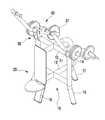
도 1 및 도 2는 본 발명의 바람직한 실시예에 따른 무게추의 조절과 분실을 방지하는 실외 근력운동기구를 나타낸 사시도이다.
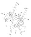
도 3은 본 발명의 바람직한 실시예에 따른 무게추의 조절과 분실을 방지하는 실외 근력운동기구를 나타낸 측면도이다.
도 4는 본 발명의 바람직한 실시예에 따른 무게추의 조절과 분실을 방지하는 실외 근력운동기구의 무게추 이동을 나타낸 사시도이다.
도 5는 본 발명의 바람직한 실시예에 따른 무게추의 조절과 분실을 방지하는 실외 근력운동기구를 나타낸 분해사시도이다.
도 6은 도 5의 일부를 확대한 확대사시도이다.
도 7은 본 발명의 바람직한 실시예에 따른 무게추의 조절과 분실을 방지하는 실외 근력운동기구의 회전부를 나타낸 분해사시도이다.
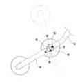
도 8은 본 발명의 바람직한 실시예에 따른 무게추의 조절과 분실을 방지하는 실외 근력운동기구의 회전부 회전반경을 나타낸 측면도이다.FIG. 1 and FIG. 2 are perspective views illustrating an outdoor muscle force exercise device for preventing adjustment and loss of weight according to a preferred embodiment of the present invention.
FIG. 3 is a side view showing an outdoor muscle force exercise device for preventing adjustment and loss of weight according to a preferred embodiment of the present invention.
FIG. 4 is a perspective view illustrating a weight movement of an outdoor muscle force exercise apparatus for preventing weight loss and loss according to a preferred embodiment of the present invention.
FIG. 5 is an exploded perspective view showing an outdoor muscle force exercise device for preventing adjustment and loss of weight according to a preferred embodiment of the present invention.
Fig. 6 is an enlarged perspective view enlarging a part of Fig. 5. Fig.
FIG. 7 is an exploded perspective view illustrating a rotating part of an outdoor strength device for preventing adjustment and loss of weight according to a preferred embodiment of the present invention.
8 is a side view showing the rotation radius of the rotary part of the outdoor muscle force exercise device for preventing the adjustment and loss of weight according to the preferred embodiment of the present invention.
본 발명의 이점 및 특징, 그리고 그것들을 달성하는 방법은 첨부되는 도면과 함께 상세하게 후술되어 있는 실시예들을 참조하면 명확해질 것이다. 그러나 본 발명은 이하에서 개시되는 실시예들에 한정되는 것이 아니라 서로 다른 다양한 형태로 구현될 수 있으며, 단지 본 실시예들은 본 발명의 개시가 완전하도록 하고, 본 발명이 속하는 기술분야에서 통상의 지식을 가진 자에게 발명의 범주를 완전하게 알려주기 위해 제공되는 것이며, 본 발명은 청구항의 범주에 의해 정의될 뿐이다. 명세서 전체에 걸쳐 동일 참조 부호는 동일 구성 요소를 지칭한다.BRIEF DESCRIPTION OF THE DRAWINGS The advantages and features of the present invention, and the manner of achieving them, will be apparent from and elucidated with reference to the embodiments described hereinafter in conjunction with the accompanying drawings. The present invention may, however, be embodied in many different forms and should not be construed as limited to the embodiments set forth herein. Rather, these embodiments are provided so that this disclosure will be thorough and complete, and will fully convey the scope of the invention to those skilled in the art. To fully disclose the scope of the invention to those skilled in the art, and the invention is only defined by the scope of the claims. Like reference numerals refer to like elements throughout the specification.
이하, 본 발명의 실시예들에 의하여 무게추의 조절과 분실을 방지하는 실외 근력운동기구를 설명하기 위한 도면들을 참고하여 본 발명에 대해 설명하도록 한다.DETAILED DESCRIPTION OF THE PREFERRED EMBODIMENTS Hereinafter, the present invention will be described with reference to the drawings for explaining an outdoor muscle force exercise apparatus for preventing the adjustment and loss of weight by the embodiments of the present invention.
도 1 및 도 2는 본 발명의 바람직한 실시예에 따른 무게추의 조절과 분실을 방지하는 실외 근력운동기구를 나타낸 사시도이다. 도 3은 본 발명의 바람직한 실시예에 따른 무게추의 조절과 분실을 방지하는 실외 근력운동기구를 나타낸 측면도이다. 도 4는 본 발명의 바람직한 실시예에 따른 무게추의 조절과 분실을 방지하는 실외 근력운동기구의 무게추 이동을 나타낸 사시도이다. 도 5는 본 발명의 바람직한 실시예에 따른 무게추의 조절과 분실을 방지하는 실외 근력운동기구를 나타낸 분해사시도이다. 도 6은 도 5의 일부를 확대한 확대사시도이다. 도 7은 본 발명의 바람직한 실시예에 따른 무게추의 조절과 분실을 방지하는 실외 근력운동기구의 회전부를 나타낸 분해사시도이다. 도 8은 본 발명의 바람직한 실시예에 따른 무게추의 조절과 분실을 방지하는 실외 근력운동기구의 회전부 회전반경을 나타낸 측면도이다.FIG. 1 and FIG. 2 are perspective views illustrating an outdoor muscle force exercise device for preventing adjustment and loss of weight according to a preferred embodiment of the present invention. FIG. 3 is a side view showing an outdoor muscle force exercise device for preventing adjustment and loss of weight according to a preferred embodiment of the present invention. FIG. 4 is a perspective view illustrating a weight movement of an outdoor muscle force exercise apparatus for preventing weight loss and loss according to a preferred embodiment of the present invention. FIG. 5 is an exploded perspective view showing an outdoor muscle force exercise device for preventing adjustment and loss of weight according to a preferred embodiment of the present invention. Fig. 6 is an enlarged perspective view enlarging a part of Fig. 5. Fig. FIG. 7 is an exploded perspective view illustrating a rotating part of an outdoor strength device for preventing adjustment and loss of weight according to a preferred embodiment of the present invention. 8 is a side view showing the rotation radius of the rotary part of the outdoor muscle force exercise device for preventing the adjustment and loss of weight according to the preferred embodiment of the present invention.
도 1 내지 도 8을 참조하면, 본 발명에 따른 무게추(37)의 도난을 방지하는 실외 근력운동기구는, 지지부(10), 벤치부(20), 회전부(30), 무게추(37) 및 추보관부(40)를 포함한다.1 to 8, an outdoor muscle force exercise apparatus for preventing the
먼저, 지지부(10)는 지면에 직립되도록 설치된다.First, the
이러한, 지지부(10)는, 중심봉(11), 제1지지부(15), 제2지지부(16), 제3지지부(17)를 포함한다.The
중심봉(11)은, 제1가로봉(12)과 제2가로봉(13)이 교차되어 '+'로 이루어진다.The
또한, 중심봉(11)은, 한 쌍으로 이루어져 상부와 하부에 서로 이격되어 설치된다. 이때, 한 쌍의 중심봉(11) 중 하부에 위치한 중심봉(11)은, 지면으로부터 이격되어 설치된다.In addition, the
여기서, 제1가로봉(12)의 양 끝단부는, 후방을 향해 절곡되되 후술할 제1지지부(15)와 제3지지부(17) 사이 대각방향으로 절곡된 절곡부(14)가 형성된다.Both end portions of the first
또한, 후술할 한 쌍의 회전부(30)는, 절곡부(14)에 각각 구비되어, 전방에 형성된 손잡이(35)가 상부에서 하부방향으로 회전될수록 이격폭이 좁아진다.Further, the pair of
즉, 사용자는, 회전부(30)를 상부에서 하부로 잡아당길 때, 사용자의 몸통 중심을 향해 잡아당길 수 있으며, 가슴근육을 모으는 동시에 자극시킬 수 있는 운동을 할 수 있다.That is, when the user pulls the
예를 들어, 본 발명의 절곡부(14)가 형성되지 않으면, 사용자는 단순히 팔을 뻗은 상태에서 손잡이(35)를 잡은 후, 사용자의 전방으로 회전부(30)를 회전시키며 잡아당긴다. 이때, 한 쌍의 회전부(30) 손잡이(35)가 서로 좁혀지지 않기 때문에 당아당기는 높이가 제한되기 때문에 원활한 운동을 할 수 없다.For example, if the
따라서, 회전부(30)를 상부에서 하부로 잡아당기며 회전시킬 때, 손잡이(35)의 폭이 좁아지면, 사용자가 회전부(30)의 전방측을 몸통 중심으로 최대한 잡아당길 수 있는 ㄷ동시에 회전부(30)를 최대한 회전시킬 수 있다.Accordingly, when the
그러므로, 제1가로봉(12)의 양 끝단부는 후방을 향해 절곡되되 제1지지부(15)와 제3지지 사이를 향한 즉, 중심봉(11)의 후방 지면을 향하는 대각방향으로 절곡된 절곡부(14)가 형성되는 것이 바람직하나, 이에 한정하지 않는다.Both ends of the first
제1지지부(15)는, 한 쌍으로 이루어져, 하나는 상하에 위치한 한 쌍의 중심봉(11) 일측을 연결하며, 지면으로부터 중심봉(11)을 지지한다.The
또한, 다른 하나의 제1지지부(15)는, 상하에 위치한 한 쌍의 중심봉(11) 타측을 연결하며 지면으로부터 중심봉(11)을 지지한다.The other
이때, 하부에 위치한 중심봉(11)보다 하부부분인 제1지지부(15)의 하부측은 외측방향으로 절곡되어 중심봉(11)을 안정적으로 지지할 뿐만 아니라, 후술할 무게추(37)에 대한 무게에 대해 안정적으로 지지될 수 있다.The lower part of the first supporting
제2지지부(16)는, 한 쌍의 중심봉(11) 전방을 각각 연결하며 지면으로부터 중심봉(11)을 지지한다.The
제3지지부(17)는, 한 쌍의 중심봉(11) 후방을 각각 연결하며 지면으로부터 중심봉(11)을 지지한다.The
이와 같이, 중심봉(11)의 좌우에는 제1지지부(15), 전방에는 제2지지부(16), 후방에는 제3지지부(17)가 구비되어, 상하의 중심봉(11)을 이격시키는 동시에 안정적으로 지지한다.As described above, the
벤치부(20)는, 지지부(10)의 전방에 구비되며, 사용자가 앉을 수 있다.The
이때, 벤치부(20)는, 제2지지부(16)의 전방에 구비되어 사용자의 등을 지지하는 등지지부(10)와 등지지부(10)의 하부에 구비되어 사용자가 앉는 좌판부를 포함한다.The
회전부(30)는, 지지부(10)의 양측에 회전가능하게 각각 구비되어, 한 쌍으로 이루어진다.The rotating
또한, 회전부(30)는, 지지판(31), 몸체(32), 회전축(33), 전방봉(34) 및 후방봉(36)을 포함한다.The rotating
지지판(31)은, 지지부(10)의 일측에 고정된다. 이때, 지지판(31)은 후술할 몸체(32)가 삽입될 수 있도록 이격되어 구비된 한 쌍으로 이루어진다.The support plate (31) is fixed to one side of the support portion (10). At this time, the
몸체(32)는, 지지판(31) 사이에 구비되며, 중앙이 관통된다. 이때, 몸체(32)의 내부에는 회전축(33)이 회전가능하게 관통되도록 회전베어링(48)이 더 구비될 수 있다. 그리고 회전베이링(48)과 몸체(32)를 연결하는 다수의 연결판(46)이 구비된다.The
또한, 연결판(46)이 구비될 때, 후술할 회전공(39)가 형성되도록 구비된다.Further, when the
그리고, 회전할 때, 후술할 회전방지축(45)의 충격을 흡수할 수 있도록 스토퍼(46)가 연결판(46)의 일측면과 타측면에 구비된다.A
이때, 스토퍼(46)의 두께를 통해서 회전공(39)의 폭을 조절할 수 있으며, 회전반경을 조절할 수 있다. 또한, 스토퍼(46)는 우레탄재질로 이루어진다.At this time, the width of the
회전축(33)은, 몸체(32) 즉, 회전베어링(48)에 회전가능하게 지지판(31)과 몸체(32)에 관통결합된다.The
이때, 몸체(32)는, 지지판(31) 사이에서 회전축(33)을 중심으로 회전된다.At this time, the
전방봉(34)은, 몸체(32)의 전방으로 돌출되고, 끝단에 손잡이(35)가 형성된다.The front bar (34) protrudes forward of the body (32), and a handle (35) is formed at the end.
이때, 몸체(32)의 전방은, 벤치부(20)가 구비된 방향이다.At this time, the front of the
또한, 전방봉(34)은, 몸체(32)의 전방으로 돌출되면서 벤치부(20) 이전에 상부로 절곡되어 돌출된다. 그리고, 전방봉(34)의 상부 끝단부에 손잡이(35)가 형성된다.In addition, the
즉, 전방봉(34)이 절곡됨에 따라, 손잡이(35)의 형성위치가 더욱 높아지기 때문에, 사용자는 더 높은 위치에서 손잡이(35)를 잡고 잡아당길 수 있다.That is, as the
후방봉(36)은, 몸체(32)의 후방으로 돌출된다.The rear bar (36) protrudes rearward of the body (32).
무게추(37)는 회전부(30)의 측부에 다수개 구비된다.A plurality of weights (37) are provided on the side of the rotary part (30).
추보관부(40)는, 다수개의 무게추(37)를 관통하여 회전부(30)의 회전축(33)과 후방봉(36)에 일단과 타단이 각각 연결된다.One end and the other end of the
이때, 무게추(37)는 추보관부(40)에 의해 회전부(30)의 회전축(33) 또는 후방봉(36)에 위치하게 된다.At this time, the
또한, 회전부(30)는 몸체(32)를 중심으로 전방봉(34)이 형성된 회전부(30)의 전방측보다 후방봉(36)이 형성되고 추보관부(40)가 구비된 회전부(30)의 후방측이 더 무겁기 때문에 회전부(30)의 전방봉(34)과 후방봉(36)이 대각방향으로 기울어지게 구비된다.The
이에 따라, 다수개의 무게추(37)가 전부 후술할 제1고정봉(41)에 위치되더라도 전방봉(34)의 끝단이 후방봉(36)의 끝단보다 높이 위치하여 사용자는 회전부(30)의 후방측 무게만으로도 운동할 수 있다.The end of the
또한, 추보관부(40)는, 일단과 타단이 몸체(32)와 후방봉(36)에 각각 결합되되, 분리가 되지 않도록 결합된다.In addition, one end and the other end of the
이에 따라, 무게추(37)는 추보관부(40)의 일단과 타단 사이만 왕복이동 가능할 수 있다.Accordingly, the
더불어, 추보관부(40)는, 무게추(37)의 도난을 방지하는 동시에 추보관부(40)로부터 무게추(37)의 분리없이 회전부(30)의 후방측 무게를 조절시킬 수 있다.In addition, the
좀 더 상세히 설명하면, 무게추(37)는 관통공이 형성된다.In more detail, the
추보관부(40)는, 제1고정봉(41), 제2고정봉(42), 연장봉(43) 및 연결봉(44)을 포함한다.The
제1고정봉(41)은, 몸체(32)의 측면에 외측으로 돌출되게 결합되되, 분리가 되지 않도록 잠금장치 등이 이용되어 결합된다.The
제2고정봉(42)은, 후방봉(36)의 측면에 외측으로 돌출되게 결합되되, 분리가 되지 않도록 잠금장치 등이 이용되어 결합된다.The
또한, 제1고정봉(41)과 제2고정봉(42)은, 무게추(37)의 관통공에 삽입되어 무게추(37)를 고정시킨다. 그리고 제1고정봉(41)과 제2고정봉(42)의 직경은 동일하며, 무게추(37)의 관통공 직경보다 작게 형성된다.The first fixing
이때, 무게추(37)가 제1고정봉(41)과 제2고정봉(42)을 따라 이동될 때 원활하게 이동되지 않도록 관통공의 내주면에는 미끄럼을 방지하는 실리콘 등과 같은 마찰력이 있는 밀착부재가 구비된다.In order to prevent the
즉, 사용자는 제1고정봉(41)과 제2고정봉(42)의 길이방향으로 무게추(37)를 이동시킬 수 있되, 밀착부재에 의해 억지이동이 이루어진다. 또한, 제1고정봉(41)과 제2고정봉(42)에 무게추(37)가 위치된 상태에서 몸체(32)가 회전축(33)을 중심으로 회전될 때, 추보관부(40)가 움직이더라도 밀착부재에 의해 제1고정봉(41)과 제2고정봉(42)에 무게추(37)가 안정적으로 고정되어,운동중에 무게추(37)가 이동되는 것을 방지하는 동시에, 갑자기 무게변화로 인한 운동중에 발생할 수 있는 안전사고를 미연에 방지할 수 있다.That is, the user can move the
연장봉(43)은, 제1고정봉(41) 및 제2고정봉(42)의 끝단에 연장되게 각각 돌출된다.The
또한, 연장봉(43)은, 제1고정봉(41) 및 제2고정봉(42)의 직경보다 작게 돌출형성된다.The
즉, 연장봉(43)의 직경은, 무게추(37)의 관통공 직경보다 작게 형성된다.That is, the diameter of the extending
연결봉(44)은, 한 쌍의 연장봉(43) 양단을 절곡되게 연결한다.The connecting
이때, 연결봉(44)은 연장봉(43)과의 연결부분이 90°가 되도록 라운드지게 연결한다.At this time, the connecting
이에 따라, 무게추(37)는, 제1고정봉(41)과 제2고정봉(42)의 직경보다 작게 형성된 연장봉(43)과 연결봉(44)을 연결하는 절곡된 연결부분을 통과할 때, 사용자의 억지이동에 의해 이동된다. 그리고 무게추(37)는 제1고정봉(41) 및 제2고정봉(42)의 어느 하나에 고정된다.The
또한, 운동 중에, 무게추(37)가 연결부분을 통과할 경우, 몸체(32)가 회전되면서 연결봉(44)의 기울기에 따라 연결봉(44) 양단 사이를 이동하게 되어, 안전사고가 발생할 수 있다.When the
이를 방지하기 위하여, 연결봉(44)에는, 일정간격으로 이격되어 제1고정봉(41)의 직경과 동일하게 돌출된 걸림부가 다수개 형성된다.In order to prevent this, the connecting
즉, 무게추(37)가 제1고정봉(41) 또는 제2고정봉(42)에서 연장봉(43)으로 이동되고, 절곡된 연결부분을 통과하여 이동하더라도 걸림부에 걸림에 따라 연결봉(44)의 기울기 변화에 따라 급격한 이동이 이루어지지 않아 안전사고를 방지할 수 있다.That is, the
한편, 몸체(32)는, 회전축(33)에 회전가능하게 결합되는 결합공(38)이 형성된다.On the other hand, the
또한, 몸체(32)는, 결합공(38)의 하부에 일정반경의 부채꼴 형상으로 회전공(39)이 형성된다.Further, the
여기서, 회전부(30)는, 회전공(39)에 삽입되도록 회전축(38)의 하부에 구비되는 회전방지축(45)을 더 포함한다.The
그리고, 몸체(32)는, 회전공(39)의 내부 일측과 타측에 회전방지축(45)이 지지되어 회전공(39)의 일정반경에 대응되게 일정반경의 각도만큼만 회전된다.The
이는, 몸체(32)가 회전될 때, 회전범위를 제한하기 위한 것이다. 즉, 회전범위가 제한되지 않는 경우, 후방축이 회전부(30)의 전방으로 회전될 수 있다. 이를 방지하기 위하여, 몸체(32)에 회전공(39)이 일정반경으로 형성된 것이다.This is for limiting the rotation range when the
이에 따라, 몸체(32)가 회전될 때, 회전방지축(45)에 의해 제한되고, 일정반경의 각도만큼만 회전되어 안전하게 운동을 할 수 있다.Accordingly, when the
본 발명이 속하는 기술분야의 통상의 지식을 가진 자는 본 발명이 그 기술적 사상이나 필수적인 특징을 변경하지 않고서 다른 구체적인 형태로 실시될 수 있다는 것을 이해할 수 있을 것이다. 그러므로 이상에서 기술한 실시예들은 모든 면에서 예시적인 것이며 한정적이 아닌 것으로 이해해야만 한다. 본 발명의 범위는 상기 상세한 설명보다는 후술하는 특허청구의 범위에 의하여 나타내어지며, 특허청구의 범위의 의미 및 범위 그리고 그 균등 개념으로부터 도출되는 모든 변경 또는 변형된 형태가 본 발명의 범위에 포함되는 것으로 해석되어야 한다. 더불어, 상술하는 과정에서 기술된 구성의 작동순서는 반드시 시계열적인 순서대로 수행될 필요는 없으며, 각 구성 및 단계의 수행 순서가 바뀌어도 본 발명의 요지를 충족한다면 이러한 과정은 본 발명의 권리범위에 속할 수 있음은 물론이다.It will be understood by those skilled in the art that the present invention may be embodied in other specific forms without departing from the spirit or essential characteristics thereof. It is therefore to be understood that the above-described embodiments are illustrative in all aspects and not restrictive. The scope of the present invention is defined by the appended claims rather than the foregoing detailed description, and all changes or modifications derived from the meaning and scope of the claims and the equivalents thereof are included in the scope of the present invention Should be interpreted. In addition, the order of operation of the components described in the above-described process does not necessarily have to be performed in a time series order, and if the order of the respective components and steps is changed, the process is included in the scope of the present invention Of course.
10 : 지지부11 : 중심봉
12 : 제1가로봉13 : 제2가로봉
14 : 절곡부15 : 제1지지부
16 : 제2지지부17 : 제3지지부
20 : 벤치부30 : 회전부
31 : 지지판32 : 몸체
33 : 회전축34 : 전방봉
35 : 손잡이36 : 후방봉
37 : 무게추38 : 결합공
39 : 회전공40 : 추보관부
41 : 제1고정봉42 : 제2고정봉
43 : 연장봉44 : 연결봉
45 : 회전방지축10: Support part 11:
12: first barb 13: second barb
14: bent portion 15: first supporting portion
16: second supporting portion 17: third supporting portion
20: bench portion 30: rotating portion
31: support plate 32: body
33: rotating shaft 34: front rod
35: handle 36: rear bar
37: Weight weight 38: Combination ball
39: Lecture 40: Chest Storage
41: first fixing rod 42: second fixing rod
43: extension rod 44: connecting rod
45: Anti-rotation axis
Claims (5)
Translated fromKorean상기 지지부의 전방에 구비되며, 사용자가 앉을 수 있는 벤치부;
상기 지지부의 양측에 회전가능하게 각각 구비된 한 쌍의 회전부;
상기 회전부의 측부에 구비되는 다수개의 무게추;
상기 다수개의 무게추를 관통하여 상기 회전부의 회전축과 후방봉에 일단과 타단이 각각 연결되는 추보관부;를 포함하고,
상기 추보관부는, 상기 무게추를 상기 추보관부의 일단과 타단 사이만 왕복이동 가능하게 하여 도난을 방지하는 동시에 상기 추보관부로부터 무게추의 분리없이 상기 회전부의 후방측 무게를 조절시키는 것을 특징으로 하고,
상기 회전부는,
상기 지지부의 일측에 고정된 한 쌍의 지지판과,
상기 지지판 사이에 구비되는 몸체와,
상기 몸체가 회전가능하게 상기 지지판과 몸체에 관통결합된 회전축과,
상기 몸체의 전방으로 돌출되고, 끝단에 손잡이가 형성된 전방봉과,
상기 몸체의 후방으로 돌출된 후방봉을 포함하고,
상기 무게추는, 관통공이 형성되고,
상기 추보관부는, 몸체의 측면과 상기 후방봉의 측면에 각각 돌출되게 결합되고, 상기 무게추의 관통공에 삽입되어 상기 무게추가 고정되는 제1고정봉 및 제2고정봉과,
상기 제1고정봉 및 제2고정봉의 끝단에 연장되게 돌출되되, 상기 제1고정봉 및 제2고정봉의 직경보다 작게 돌출형성된 한 쌍의 연장봉 및
상기 한 쌍의 연장봉 양단을 절곡되게 연결하되, 연결부분을 라운드지게 연결하는 연결봉을 포함하고,
상기 무게추는, 상기 제1고정봉과 제2고정봉의 직경보다 작게 형성된 상기 연장봉과 연결봉을 연결하는 절곡된 연결부분을 통과할 때, 사용자의 억지이동에 의해 이동되어, 상기 제1고정봉 및 제2고정봉의 어느 하나에 고정되는 것을 특징으로 하는 무게추의 조절과 분실을 방지하는 실외 근력운동기구.
A support provided to stand upright on the ground;
A bench portion provided at the front of the support portion and capable of being seated by the user;
A pair of rotating parts rotatably provided on both sides of the support part;
A plurality of weights provided on the side of the rotation unit;
And a weight storing part passing through the plurality of weight weights and having one end and the other end connected to the rotating shaft and the rear rod of the rotating part, respectively,
Wherein the weight storing part is configured to allow the weight to be reciprocated only between one end and the other end of the weight storing part to prevent theft and adjust the weight of the rear part of the rotating part without separating the weight from the weight storing part and,
The rotation unit includes:
A pair of support plates fixed to one side of the support portion,
A body provided between the support plates,
A rotating shaft rotatably connected to the supporting plate and the body through the body,
A front bar protruding forward of the body and having a handle at an end thereof,
And a rear bar protruding rearward of the body,
Wherein the weight is formed with a through hole,
The weight storing part includes a first fixing rod and a second fixing rod which are coupled to the side surface of the body and the side surface of the rear rod so as to be protruded and inserted into the through holes of the weight,
A pair of extension rods protruding from the ends of the first and second fixed rods and protruding to be smaller than the diameters of the first and second fixed rods;
And a connecting rod for bending the opposite ends of the pair of extension rods and connecting the connection portions in a round manner,
Wherein the weight is moved by the user's constraint movement when passing through the bent connecting portion connecting the extending rod and the connecting rod formed to be smaller than the diameters of the first fixing bar and the second fixing bar, Wherein the fixed weight is fixed to one of the fixed rods.
상기 지지부는,
제1가로봉과 제2가로봉이 교차되어 '+'로 이루어지고, 상부와 하부에 서로 이격되어 설치되는 한 쌍의 중심봉와,
상기 한 쌍의 중심봉 일측과 타측을 연결하며 지면으로부터 상기 중심봉을 지지하는 한 쌍의 제1지지부와
상기 한 쌍의 중심봉 전방을 각각 연결하며 지면으로부터 상기 중심봉을 지지하는 제2지지부 및
상기 한 쌍의 중심봉 후방을 각각 연결하며 지면으로부터 상기 중심봉을 지지하는 제3지지부를 포함하고,
상기 벤치부는, 상기 제2지지부의 전방에 구비되어 사용자의 등을 지지하는 등지지부와 상기 등지지부의 하부에 구비되어 사용자가 앉는 좌판부를 포함하는 무게추의 조절과 분실을 방지하는 실외 근력운동기구.
The method according to claim 1,
The support portion
A pair of central rods which are formed by intersecting the first transverse bar and the second transverse bar to form '+'
A pair of first supporting portions for connecting the one side of the pair of center rods and the other side and supporting the center rods from the ground;
A second support portion connecting the front ends of the pair of center rods and supporting the center rods from the ground,
And a third support portion connecting the rear ends of the center rods and supporting the center rods from the ground,
The bench portion includes a back support provided at the front of the second support portion to support a user's back and a seat portion provided at a lower portion of the back support portion for seating the user, .
상기 제1가로봉의 양 끝단부는, 후방을 향해 절곡되되 상기 제1지지부와 제3지지부 사이 대각방향으로 절곡된 절곡부가 형성되고,
상기 한 쌍의 회전부는, 상기 절곡부에 각각 구비되어, 전방에 형성된 손잡이가 상부에서 하부방향으로 회전될수록 이격폭이 좁아지고,
사용자는, 상기 회전부를 상부에서 하부로 잡아당길 때, 사용자의 몸통 중심을 향해 잡아당기며 가슴근육을 모으는 동시에 자극시키며 운동하는 것을 특징으로 하는 무게추의 조절과 분실을 방지하는 실외 근력운동기구.
3. The method of claim 2,
Wherein both end portions of the first transverse bar are bent toward the rear, and bent portions bent in the diagonal direction between the first and third support portions are formed,
The pair of rotating parts are respectively provided in the bent parts, and as the handle formed in the front is rotated from the upper part to the lower part,
The user pulls the rotation part from the upper part to the lower part and pulls toward the center of the body of the user to collect the muscles of the chest while stimulating the muscles and exercising the muscles.
상기 몸체는, 상기 회전축에 회전가능하게 결합되는 결합공이 형성되고, 상기 결합공의 하부에 일정반경의 부채꼴 형상으로 회전공이 형성되고,
상기 회전부는, 상기 회전공에 삽입되도록 상기 회전축의 하부에 구비되는 회전방지축을 더 포함하고,
상기 몸체는, 상기 회전공의 내부 일측과 타측에 상기 회전방지축이 지지되어 상기 일정반경에 대응되게 회전되는 것을 특징으로 하는 무게추의 조절과 분실을 방지하는 실외 근력운동기구.
The method according to claim 1,
Wherein the body is formed with a coupling hole rotatably coupled to the rotary shaft, a rotary hole is formed in a lower part of the coupling hole in a fan shape having a predetermined radius,
The rotation unit may further include a rotation preventing shaft provided below the rotation shaft to be inserted into the rotation hole,
Wherein the body is supported on one side and the other side of the rotary shaft so as to be rotatable corresponding to the predetermined radius, wherein the weight is adjusted and prevented from being lost.
Priority Applications (1)
| Application Number | Priority Date | Filing Date | Title |
|---|---|---|---|
| KR1020180138578AKR101951607B1 (en) | 2018-11-13 | 2018-11-13 | Outdoor muscle strength device |
Applications Claiming Priority (1)
| Application Number | Priority Date | Filing Date | Title |
|---|---|---|---|
| KR1020180138578AKR101951607B1 (en) | 2018-11-13 | 2018-11-13 | Outdoor muscle strength device |
Publications (1)
| Publication Number | Publication Date |
|---|---|
| KR101951607B1true KR101951607B1 (en) | 2019-02-22 |
Family
ID=65584791
Family Applications (1)
| Application Number | Title | Priority Date | Filing Date |
|---|---|---|---|
| KR1020180138578AExpired - Fee RelatedKR101951607B1 (en) | 2018-11-13 | 2018-11-13 | Outdoor muscle strength device |
Country Status (1)
| Country | Link |
|---|---|
| KR (1) | KR101951607B1 (en) |
Cited By (3)
| Publication number | Priority date | Publication date | Assignee | Title |
|---|---|---|---|---|
| CN110496369A (en)* | 2019-09-26 | 2019-11-26 | 山东力之星健身科技有限公司 | multifunctional trainer |
| KR20230008520A (en) | 2021-07-07 | 2023-01-16 | 울산대학교 산학협력단 | A upper body muscles strengthening exercise device using electro-hydraulic actuator |
| KR102526043B1 (en)* | 2022-03-30 | 2023-04-25 | 전대성 | Outdoor type bench press with adjustable handle height |
Citations (4)
| Publication number | Priority date | Publication date | Assignee | Title |
|---|---|---|---|---|
| US5429570A (en)* | 1993-12-23 | 1995-07-04 | Beyer; Eric L. | Free weight exercise device |
| US20120004080A1 (en)* | 2010-03-31 | 2012-01-05 | Nautilus, Inc. | Lockout mechanism for a weight stack exercise machine |
| KR101787699B1 (en) | 2017-04-14 | 2017-10-18 | 박기찬 | Field bench press to control weight |
| US20180085621A1 (en)* | 2008-10-17 | 2018-03-29 | Hoist Fitness Systems, Inc. | Exercise machine with lifting arm |
- 2018
- 2018-11-13KRKR1020180138578Apatent/KR101951607B1/ennot_activeExpired - Fee Related
Patent Citations (4)
| Publication number | Priority date | Publication date | Assignee | Title |
|---|---|---|---|---|
| US5429570A (en)* | 1993-12-23 | 1995-07-04 | Beyer; Eric L. | Free weight exercise device |
| US20180085621A1 (en)* | 2008-10-17 | 2018-03-29 | Hoist Fitness Systems, Inc. | Exercise machine with lifting arm |
| US20120004080A1 (en)* | 2010-03-31 | 2012-01-05 | Nautilus, Inc. | Lockout mechanism for a weight stack exercise machine |
| KR101787699B1 (en) | 2017-04-14 | 2017-10-18 | 박기찬 | Field bench press to control weight |
Cited By (3)
| Publication number | Priority date | Publication date | Assignee | Title |
|---|---|---|---|---|
| CN110496369A (en)* | 2019-09-26 | 2019-11-26 | 山东力之星健身科技有限公司 | multifunctional trainer |
| KR20230008520A (en) | 2021-07-07 | 2023-01-16 | 울산대학교 산학협력단 | A upper body muscles strengthening exercise device using electro-hydraulic actuator |
| KR102526043B1 (en)* | 2022-03-30 | 2023-04-25 | 전대성 | Outdoor type bench press with adjustable handle height |
Similar Documents
| Publication | Publication Date | Title |
|---|---|---|
| US10486012B2 (en) | Exercise machine with a detachable stabilizing support assembly having adjustable positions | |
| US20250152996A1 (en) | Translating carriage exercise machines and methods of use | |
| GB2567347B (en) | Rowing machine | |
| US8968164B2 (en) | Exercise apparatus and method with sliding handle assembly | |
| US8062196B1 (en) | Abdominal exercise apparatus | |
| KR101951607B1 (en) | Outdoor muscle strength device | |
| US7537554B2 (en) | Multi-functional personal fitness apparatus | |
| AU577669B2 (en) | Exercise device | |
| US7780586B2 (en) | Training bench | |
| US9168416B2 (en) | Abdomen exercise machine | |
| CA2721497C (en) | Improved abdominal exerciser with rotatable seat and tandem pulley features | |
| US20120021876A1 (en) | Adjustable cable machine | |
| EP1649904A2 (en) | Weight station with add-on weights | |
| US9126073B2 (en) | Abdomen exercise machine | |
| US20060166799A1 (en) | Abdominal exercise apparatus | |
| RU2566309C2 (en) | Mechanical simulator for abdominals | |
| US9474922B2 (en) | Combination exercise machine for performing pilates and barre workouts | |
| JP2008220978A (en) | Collapsible exerciser | |
| US7435207B2 (en) | Collapsible and storable apparatus for exercising core muscles | |
| US5669860A (en) | Device for exercising the lower back | |
| KR20180002205U (en) | Self-assembly multi gym | |
| EP1967235A1 (en) | Gymnastic apparatus for muscle training, particularly of the bench type | |
| JP6688904B2 (en) | Exercise equipment | |
| JP6535940B2 (en) | Exercise aid | |
| CA2103013A1 (en) | Upper torso rotary exercise device |
Legal Events
| Date | Code | Title | Description |
|---|---|---|---|
| PA0109 | Patent application | St.27 status event code:A-0-1-A10-A12-nap-PA0109 | |
| PA0201 | Request for examination | St.27 status event code:A-1-2-D10-D11-exm-PA0201 | |
| PA0302 | Request for accelerated examination | St.27 status event code:A-1-2-D10-D17-exm-PA0302 St.27 status event code:A-1-2-D10-D16-exm-PA0302 | |
| D13-X000 | Search requested | St.27 status event code:A-1-2-D10-D13-srh-X000 | |
| D14-X000 | Search report completed | St.27 status event code:A-1-2-D10-D14-srh-X000 | |
| E902 | Notification of reason for refusal | ||
| PE0902 | Notice of grounds for rejection | St.27 status event code:A-1-2-D10-D21-exm-PE0902 | |
| E13-X000 | Pre-grant limitation requested | St.27 status event code:A-2-3-E10-E13-lim-X000 | |
| P11-X000 | Amendment of application requested | St.27 status event code:A-2-2-P10-P11-nap-X000 | |
| P13-X000 | Application amended | St.27 status event code:A-2-2-P10-P13-nap-X000 | |
| T11-X000 | Administrative time limit extension requested | St.27 status event code:U-3-3-T10-T11-oth-X000 | |
| PE0801 | Dismissal of amendment | St.27 status event code:A-2-2-P10-P12-nap-PE0801 | |
| E701 | Decision to grant or registration of patent right | ||
| GRNT | Written decision to grant | ||
| PE0701 | Decision of registration | St.27 status event code:A-1-2-D10-D22-exm-PE0701 | |
| PR0701 | Registration of establishment | St.27 status event code:A-2-4-F10-F11-exm-PR0701 | |
| PR1002 | Payment of registration fee | St.27 status event code:A-2-2-U10-U11-oth-PR1002 Fee payment year number:1 | |
| PG1601 | Publication of registration | St.27 status event code:A-4-4-Q10-Q13-nap-PG1601 | |
| P14-X000 | Amendment of ip right document requested | St.27 status event code:A-5-5-P10-P14-nap-X000 | |
| PN2301 | Change of applicant | St.27 status event code:A-5-5-R10-R11-asn-PN2301 | |
| P16-X000 | Ip right document amended | St.27 status event code:A-5-5-P10-P16-nap-X000 | |
| PN2301 | Change of applicant | St.27 status event code:A-5-5-R10-R14-asn-PN2301 | |
| R18-X000 | Changes to party contact information recorded | St.27 status event code:A-5-5-R10-R18-oth-X000 | |
| R18-X000 | Changes to party contact information recorded | St.27 status event code:A-5-5-R10-R18-oth-X000 | |
| R18-X000 | Changes to party contact information recorded | St.27 status event code:A-5-5-R10-R18-oth-X000 | |
| PR1001 | Payment of annual fee | St.27 status event code:A-4-4-U10-U11-oth-PR1001 Fee payment year number:4 | |
| R18-X000 | Changes to party contact information recorded | St.27 status event code:A-5-5-R10-R18-oth-X000 | |
| PC1903 | Unpaid annual fee | St.27 status event code:A-4-4-U10-U13-oth-PC1903 Not in force date:20230219 Payment event data comment text:Termination Category : DEFAULT_OF_REGISTRATION_FEE | |
| R18-X000 | Changes to party contact information recorded | St.27 status event code:A-5-5-R10-R18-oth-X000 | |
| K11-X000 | Ip right revival requested | St.27 status event code:A-6-4-K10-K11-oth-X000 | |
| PC1903 | Unpaid annual fee | St.27 status event code:N-4-6-H10-H13-oth-PC1903 Ip right cessation event data comment text:Termination Category : DEFAULT_OF_REGISTRATION_FEE Not in force date:20230219 | |
| PR0401 | Registration of restoration | St.27 status event code:A-6-4-K10-K13-oth-PR0401 | |
| PR1001 | Payment of annual fee | St.27 status event code:A-4-4-U10-U11-oth-PR1001 Fee payment year number:5 | |
| PC1903 | Unpaid annual fee | St.27 status event code:A-4-4-U10-U13-oth-PC1903 Not in force date:20240219 Payment event data comment text:Termination Category : DEFAULT_OF_REGISTRATION_FEE | |
| R18-X000 | Changes to party contact information recorded | St.27 status event code:A-5-5-R10-R18-oth-X000 | |
| K11-X000 | Ip right revival requested | St.27 status event code:A-6-4-K10-K11-oth-X000 | |
| PC1903 | Unpaid annual fee | St.27 status event code:N-4-6-H10-H13-oth-PC1903 Ip right cessation event data comment text:Termination Category : DEFAULT_OF_REGISTRATION_FEE Not in force date:20240219 | |
| PR0401 | Registration of restoration | St.27 status event code:A-6-4-K10-K13-oth-PR0401 | |
| PR1001 | Payment of annual fee | St.27 status event code:A-4-4-U10-U11-oth-PR1001 Fee payment year number:6 | |
| PR1001 | Payment of annual fee | St.27 status event code:A-4-4-U10-U11-oth-PR1001 Fee payment year number:7 |