KR101950704B1 - Circuits and methods for processing a signal generated by a plurality of measuring devices - Google Patents
Circuits and methods for processing a signal generated by a plurality of measuring devicesDownload PDFInfo
- Publication number
- KR101950704B1 KR101950704B1KR1020137030277AKR20137030277AKR101950704B1KR 101950704 B1KR101950704 B1KR 101950704B1KR 1020137030277 AKR1020137030277 AKR 1020137030277AKR 20137030277 AKR20137030277 AKR 20137030277AKR 101950704 B1KR101950704 B1KR 101950704B1
- Authority
- KR
- South Korea
- Prior art keywords
- signal
- magnetic field
- digitally converted
- bit
- circuit
- Prior art date
- Legal status (The legal status is an assumption and is not a legal conclusion. Google has not performed a legal analysis and makes no representation as to the accuracy of the status listed.)
- Active
Links
- 238000000034methodMethods0.000titleclaimsabstractdescription51
- 238000012545processingMethods0.000titleclaimsdescription9
- 230000005291magnetic effectEffects0.000claimsabstractdescription193
- 238000005259measurementMethods0.000claimsabstractdescription52
- 238000007781pre-processingMethods0.000claimsdescription82
- 238000012805post-processingMethods0.000claimsdescription40
- 238000001914filtrationMethods0.000claimsdescription21
- 239000000758substrateSubstances0.000claimsdescription17
- 230000004044responseEffects0.000claimsdescription9
- 239000007943implantSubstances0.000claimsdescription7
- 238000010586diagramMethods0.000description11
- 230000008859changeEffects0.000description6
- 230000005355Hall effectEffects0.000description5
- 230000035945sensitivityEffects0.000description5
- 230000008901benefitEffects0.000description3
- 239000003990capacitorSubstances0.000description3
- 230000005294ferromagnetic effectEffects0.000description3
- 230000010354integrationEffects0.000description3
- 238000013459approachMethods0.000description2
- 239000004020conductorSubstances0.000description2
- 230000003321amplificationEffects0.000description1
- 238000010276constructionMethods0.000description1
- 238000001514detection methodMethods0.000description1
- 230000000694effectsEffects0.000description1
- 230000007613environmental effectEffects0.000description1
- WPYVAWXEWQSOGY-UHFFFAOYSA-Nindium antimonideChemical compound[Sb]#[In]WPYVAWXEWQSOGY-UHFFFAOYSA-N0.000description1
- 230000005381magnetic domainEffects0.000description1
- 238000003199nucleic acid amplification methodMethods0.000description1
- 230000008569processEffects0.000description1
- 238000003672processing methodMethods0.000description1
- 239000011347resinSubstances0.000description1
- 229920005989resinPolymers0.000description1
- 238000009738saturatingMethods0.000description1
- 230000007704transitionEffects0.000description1
- 230000005641tunnelingEffects0.000description1
Images


Classifications
- G—PHYSICS
- G01—MEASURING; TESTING
- G01R—MEASURING ELECTRIC VARIABLES; MEASURING MAGNETIC VARIABLES
- G01R33/00—Arrangements or instruments for measuring magnetic variables
- G01R33/0023—Electronic aspects, e.g. circuits for stimulation, evaluation, control; Treating the measured signals; calibration
- G01R33/0029—Treating the measured signals, e.g. removing offset or noise
- G—PHYSICS
- G01—MEASURING; TESTING
- G01R—MEASURING ELECTRIC VARIABLES; MEASURING MAGNETIC VARIABLES
- G01R33/00—Arrangements or instruments for measuring magnetic variables
- G01R33/02—Measuring direction or magnitude of magnetic fields or magnetic flux
- G01R33/06—Measuring direction or magnitude of magnetic fields or magnetic flux using galvano-magnetic devices
- G—PHYSICS
- G01—MEASURING; TESTING
- G01R—MEASURING ELECTRIC VARIABLES; MEASURING MAGNETIC VARIABLES
- G01R19/00—Arrangements for measuring currents or voltages or for indicating presence or sign thereof
- G01R19/25—Arrangements for measuring currents or voltages or for indicating presence or sign thereof using digital measurement techniques
- G01R19/257—Arrangements for measuring currents or voltages or for indicating presence or sign thereof using digital measurement techniques using analogue/digital converters of the type with comparison of different reference values with the value of voltage or current, e.g. using step-by-step method
- G—PHYSICS
- G01—MEASURING; TESTING
- G01R—MEASURING ELECTRIC VARIABLES; MEASURING MAGNETIC VARIABLES
- G01R33/00—Arrangements or instruments for measuring magnetic variables
- G01R33/02—Measuring direction or magnitude of magnetic fields or magnetic flux
- G01R33/06—Measuring direction or magnitude of magnetic fields or magnetic flux using galvano-magnetic devices
- G01R33/07—Hall effect devices
- G01R33/077—Vertical Hall-effect devices
Landscapes
- Physics & Mathematics (AREA)
- General Physics & Mathematics (AREA)
- Condensed Matter Physics & Semiconductors (AREA)
- Transmission And Conversion Of Sensor Element Output (AREA)
- Hall/Mr Elements (AREA)
- Measuring Magnetic Variables (AREA)
- Measurement Of Length, Angles, Or The Like Using Electric Or Magnetic Means (AREA)
Abstract
Translated fromKoreanDescription
Translated fromKorean본 발명은 일반적으로 전자 회로들에 관한 것으로, 보다 구체적으로, 복수의 측정 장치에 의해 감지된 파라미터의 방향의 각도를 신속하게 확인할 수 있는 전자 회로에 관한 것이다.BACKGROUND OF THE
알려진 바와 같이, 감지 소자들은 환경 특성치를 감지하는 다양한 응용들에 이용되고 있다. 이러한 감지 소자들은 압력 감지 소자들, 온도 감지 소자들, 광 감지 소자들, 음향 감지 소자들, 및 자기장 감지 소자들을 포함하고, 다만, 이러한 예들에 한정되지 않는다.As is known, sensing elements are being used in a variety of applications to sense environmental characteristics. These sensing elements include, but are not limited to, pressure sensing elements, temperature sensing elements, light sensing elements, acoustic sensing elements, and magnetic field sensing elements.
자기장 센서들은 다양한 응용들에서 사용될 수 있다. 일 응용예로서, 자기장 센서는 자기장의 방향을 검출하는 데에 이용될 수 있다. 다른 응용예로서, 자기장 센서는 전류를 감지하는 데에 이용될 수 있다. 전류 센서의 한 종류는 전류-운반 전도체(current-carrying conductor)에 근접한 홀 효과(Hall effect) 자기장 감지 소자를 이용한다.Magnetic field sensors can be used in a variety of applications. As one application, a magnetic field sensor can be used to detect the direction of the magnetic field. As another application, a magnetic field sensor can be used to sense current. One type of current sensor utilizes a Hall effect magnetic field sensing element close to the current-carrying conductor.
평면 홀(planar Hall) 소자들 및 수직 홀(vertical Hall) 소자들은 자기장 센서들에 사용될 수 있는 것으로 알려진 자기장 감지 소자의 종류들이다. 평면 홀 소자는 일반적으로 상기 평면 홀 소자가 형성된 기판의 표면에 직교하는 자기장에 응답한다. 수직 홀 소자는 일반적으로 상기 수직 홀 소자가 형성된 기판의 표면에 평행한 자기장에 응답한다.Planar Hall elements and vertical Hall elements are types of magnetic field sensing elements known to be usable in magnetic field sensors. The planar Hall element generally responds to a magnetic field perpendicular to the surface of the substrate on which the planar Hall element is formed. The vertical Hall element generally responds to a magnetic field parallel to the surface of the substrate on which the vertical Hall element is formed.
다른 종류의 자기장 감지 소자들 또한 알려져 있다. 예를 들어, 복수의 수직 자기장 감지 소자들을 포함하는 소위 "원형 수직 홀(circular vertical Hall)" (CVH) 감지 소자가 알려져 있고, 이는 2008년 5월 28일자로 출원되고, PCT공개번호 제WO2008/145662호로 영어로 공개된 PCT특허출원번호 제PCT/EP2008/056517호, "Magnetic Field Sensor for Measuring Direction of a Magnetic Field in a Plane"에 개시되어 있다. 이러한 출원서 및 공개공보는 전체로서 여기에 참조로 포함된다. 상기 CVH 감지 소자는 기판의 공통 원형 임플란트(implant) 영역 상부에 배치되는 수직 홀 소자들의 원형 배치를 가진다. 상기 CVH 감지 소자는 상기 기판 평면에서의 자기장의 방향(또한 선택적으로 세기)을 감지하는 데에 이용될 수 있다.Other types of magnetic field sensing elements are also known. For example, a so-called "circular vertical Hall" (CVH) sensing element including a plurality of vertical magnetic field sensing elements is known, which is filed on May 28, 2008 and described in PCT Publication No. WO2008 / No. < / RTI > No. 145662, published in PCT Patent Application No. PCT / EP2008 / 056517, " Magnetic Field Sensor for Measuring Direction of a Magnetic Field in a Plane ". Such applications and publications are incorporated herein by reference in their entirety. The CVH sensing element has a circular arrangement of vertical Hall elements disposed above a common circular implant region of the substrate. The CVH sensing element may be used to sense the direction of the magnetic field in the substrate plane (and also optionally the intensity).
종래에는, 자기장의 방향을 결정하기 위해서는 CVH 감지 소자 내의 복수의 수직 홀 소자들로부터의 모든 출력 신호들이 필요하였다. 또한 종래에는, CVH 감지 소자의 수직 홀 소자들로부터의 출력 신호들이 순차적으로 생성되었고, 따라서 CVH 감지 소자로부터의 상기 출력 신호들이 모두 생성되는 데에 상당한 시간이 소요되었다. 이에 따라, 자기장의 방향을 결정하는 데에 상당한 시간이 걸릴 수 있다.Conventionally, all output signals from a plurality of vertical Hall elements in a CVH sensing element were required to determine the direction of the magnetic field. Also, conventionally, output signals from the vertical Hall elements of the CVH sensing element have been sequentially generated, and thus it has taken a considerable amount of time for all of the output signals from the CVH sensing element to be generated. Accordingly, it may take a considerable time to determine the direction of the magnetic field.
다양한 파라미터들이, 일반적으로 감지 소자들 (및 감지 소자들을 이용하는 센서들), 구체적으로 자기장 감지 소자들 (및 자기장 센서들)의 성능을 나타낸다. 자기장 감지 소자의 예에서, 이러한 파라미터들로서, 상기 자기장 감지 소자에 의해 감지된 자기장의 변화에 따른 상기 자기장 감지 소자의 출력 신호의 변화를 나타내는 감도(sensitivity), 상기 자기장에 직접 비례하여 상기 자기장 감지 소자의 상기 출력 신호가 변화하는 정도를 나타내는 선형성(linearity) 등이 있다. 또한, 이러한 파라미터들은 상기 자기장 센서가 0(zero) 자기장을 감지함에도 상기 0 자기장을 나타내지 않는 상기 자기장 감지 소자의 출력 신호에 의해 특징지어지는 오프셋(offset)을 포함한다. 다른 종류의 감지 소자들 또한, 상기 감지 소자가 0(zero) 감지 특성치를 감지할 때 상기 0 감지 특성치를 나타내지 않는 각 출력 신호 오프셋을 가질 수 있다.Various parameters generally represent the performance of the sensing elements (and sensors using the sensing elements), specifically the magnetic field sensing elements (and the magnetic field sensors). In the example of the magnetic field sensing element, these parameters include a sensitivity indicating a change in the output signal of the magnetic field sensing element in accordance with a change in the magnetic field sensed by the magnetic field sensing element, And a linearity indicating the degree to which the output signal of the output signal varies. These parameters also include an offset characterized by the output signal of the magnetic field sensing element which does not exhibit the zero magnetic field even though the magnetic field sensor senses a zero magnetic field. Other types of sensing elements may also have respective output signal offsets that do not exhibit the zero sensing characteristic when the sensing element senses a zero sensing characteristic.
센서(예를 들어, 자기장 센서)의 성능을 나타낼 수 있는 다른 파라미터로서, 연관된 감지 소자들(예를 들어, 자기장 감지 소자들)로부터의 출력 신호들이 샘플링되는 속도가 있다.As another parameter that can represent the performance of a sensor (e.g., a magnetic field sensor), there is a rate at which output signals from associated sensing elements (e.g., magnetic field sensing elements) are sampled.
자기장 센서들은 자기장의 방향을 확인하도록 이용될 수 있다. 예를 들어, 일 응용예에서, 자기장 센서는 자석이 배치된 목표물의 회전 속도를 확인하는 데에 이용될 수 있다. 자기장 센서는, 상기 자기장 센서가 상기 자기장의 방향을 얼마나 신속하게 확인할 수 있는지에 관하여 한계를 가질 수 있고, 따라서, 상기 목표물이 얼마나 신속하게 회전하는지를 상기 자기장 센서에 의해 정확하게 감지하는 데에 한계를 가질 수 있다. 특히, 복수의 자기장 감지 소자들(예를 들어, CVH 감지 소자)을 이용하는 자기장 센서에서는, 이들이 순차적으로 스캔되므로, 상기 자기장 센서의 이러한 한계가 용인되지 않을 수 있다.Magnetic field sensors can be used to identify the direction of the magnetic field. For example, in one application, a magnetic field sensor may be used to identify the rotational speed of the target on which the magnet is disposed. The magnetic field sensor may have a limit as to how quickly the direction of the magnetic field can be identified by the magnetic field sensor and thus have a limitation in accurately sensing how fast the target rotates by the magnetic field sensor . In particular, in a magnetic field sensor using a plurality of magnetic field sensing elements (e.g. CVH sensing elements), this limitation of the magnetic field sensor may not be tolerated since they are scanned sequentially.
그러므로, 자기장의 방향을 보다 신속하게 확인할 수 있는 자기장 센서를 제공하는 것이 바람직하다. 보다 일반적으로, 복수의 측정 장치들에 의해 감지된 파라미터의 방향의 각도를 보다 신속하게 확인할 수 있는 회로를 제공하는 것이 바람직하다.Therefore, it is desirable to provide a magnetic field sensor that can more quickly confirm the direction of the magnetic field. More generally, it is desirable to provide a circuit that can more quickly identify the angle of the direction of the parameter sensed by a plurality of measurement devices.
본 발명의 목적은 복수의 측정 장치들에 의해 감지된 파라미터의 방향의 각도를 보다 신속하게 확인할 수 있는 회로 및 방법을 제공하는 것이다.It is an object of the present invention to provide a circuit and a method which can more quickly confirm the angle of the direction of the parameter sensed by the plurality of measuring devices.
본 발명은 자기장의 방향의 보다 신속하게 확인할 수 있는 자기장 센서를 제공한다. 이는 복수의 자기장 감지 소자들을 채용하는 자기장 센서 실시예들에서 특히 유용하다.The present invention provides a magnetic field sensor that can more quickly identify the direction of a magnetic field. This is particularly useful in magnetic field sensor embodiments employing a plurality of magnetic field sensing elements.
보다 일반적으로, 본 발명은 복수의 감지 소자들에 의해 감지된 파라미터의 방향의 각도를 보다 신속하게 확인할 수 있는 회로를 제공한다. 일 실시예에서, 상기 감지된 파라미터는 자기장이고, 상기 감지 소자들은 자기장 센서들이다. 그러나, 다른 실시예에서, 상기 감지 소자들은 다른 종류의 감지 소자, 예를 들어, 음향 감지 소자들이고, 상기 감지된 파라미터는 다른 종류의 감지된 파라미터, 예를 들어 음향의 음압일 수 있다.More generally, the present invention provides a circuit that can more quickly identify the angle of the direction of a parameter sensed by a plurality of sensing elements. In one embodiment, the sensed parameter is a magnetic field and the sensing elements are magnetic field sensors. However, in other embodiments, the sensing elements may be other types of sensing elements, e.g., acoustic sensing elements, and the sensed parameters may be other types of sensed parameters, such as sound pressure of sound.
본 발명의 일 측면에 따라, 전자 회로는 상응하는 복수의 측정 장치 신호들을 생성하는 복수의 측정 장치들을 포함한다. 상기 복수의 측정 장치 신호들 각각은 감지된 파라미터의 방향의 각도와 관련된 크기를 가진다. 상기 전자 회로는 상기 복수의 측정 장치 신호들을 나타내는 신호를 수신하고, 상기 복수의 측정 장치들 중 하나 이상의 측정 장치의 선택을 나타내는 인덱스 값을 수신하며, 상기 인덱스 값에 따라 선택되는 상기 복수의 측정 장치 신호들 중 선택된 하나 이상을 나타내는 제1 전처리 출력 신호, 또는 상기 인덱스 값에 따라 선택되는 상기 복수의 측정 장치 신호들을 나타내는 신호들의 선택된 세트의 합을 나타내는 제2 전처리 출력 신호를 생성하는 전처리(preprocessing) 회로를 더 포함한다. 상기 전자 회로는 상기 제1 또는 제2 전처리 출력 신호를 수신하고, 상기 제1 또는 제2 전처리 출력 신호의 소정의 값 교차(crossing)를 상기 인덱스 값에 연관짓는 후처리(post processing) 회로를 더 포함한다. 상기 소정의 값 교차는 상기 감지된 파라미터의 상기 방향의 상기 각도를 나타낸다. 상기 후처리 회로는, 상기 제1 또는 제2 전처리 출력 신호를 나타내는 신호를 수신하고, 상기 인덱스 값에 상응하는 디지털 변환된 신호를 생성하는 아날로그-디지털 변환기를 포함한다.According to an aspect of the invention, an electronic circuit includes a plurality of measurement devices for generating corresponding plurality of measurement device signals. Each of the plurality of measurement device signals has a magnitude related to an angle of a direction of a sensed parameter. The electronic circuit receiving a signal representative of the plurality of measurement device signals and receiving an index value representative of a selection of one or more of the plurality of measurement devices, A preprocessing for generating a second pre-processing output signal representing a sum of a first preprocessed output signal representing a selected one or more of the signals, or a selected set of signals representing the plurality of measurement device signals selected in accordance with the index value, Circuit. The electronic circuit further includes a post processing circuit for receiving the first or second pre-processing output signal and associating a predetermined value crossing of the first or second pre-processing output signal with the index value . The predetermined value intersection represents the angle in the direction of the sensed parameter. The post-processing circuit includes an analog-to-digital converter for receiving the signal representing the first or second pre-processing output signal and for generating a digitally converted signal corresponding to the index value.
하나 이상의 상기 측면들은 하나 이상의 다음의 특징들을 포함할 수 있다.One or more of the above aspects may include one or more of the following features.
상기 전자 회로의 일 실시예에서, 상기 복수의 측정 장치들은 복수의 자기장 감지 소자들에 상응하고, 상기 감지된 파라미터는 자기장에 상응한다.In one embodiment of the electronic circuit, the plurality of measurement devices correspond to a plurality of magnetic field sensing elements, and the sensed parameter corresponds to a magnetic field.
상기 전자 회로의 일 실시예에서, 상기 전자 회로는 상기 제1 또는 제2 전처리 출력 신호를 수신하고, 적분 신호를 생성하는 적분기(integrator)를 더 포함하고, 상기 아날로그-디지털 변환기는 상기 적분 신호를 수신하고, 상기 적분 신호에 따라 상기 디지털 변환된 신호를 생성한다.In one embodiment of the electronic circuit, the electronic circuit further comprises an integrator for receiving the first or second pre-processing output signal and for generating an integral signal, wherein the analog-to-digital converter converts the integral signal And generates the digitally converted signal according to the integration signal.
일 실시예에서, 상기 후처리 회로는, 상기 디지털 변환된 신호를 수신하고, 상기 감지된 파라미터의 상기 방향의 상기 각도를 나타내는 디지털 필터링된 신호를 제공하도록 상기 디지털 변환된 신호를 필터링하는 디지털 필터를 더 포함한다.In one embodiment, the post-processing circuit comprises a digital filter for receiving the digitally converted signal and filtering the digitally converted signal to provide a digitally filtered signal representative of the angle of the direction of the sensed parameter .
일 실시예에서, 상기 디지털 필터는 데시메이션(decimation) 필터를 포함한다.In one embodiment, the digital filter includes a decimation filter.
일 실시예에서, 상기 후처리 회로는, 상기 디지털 변환된 신호를 수신하고, 시간 구간 내에 상기 디지털 변환된 신호의 최하위 비트에서의 0 및 1의 발생 횟수들에 각각 상응하는 제1 및 제2 카운트 값들을 생성하는 카운트 회로, 및 상기 제1 카운트 값을 상기 제2 카운트 값에 비교하고, 상기 감지된 파라미터의 상기 방향의 상기 각도를 나타내는 카운트 비교 값을 생성하는 비교 회로를 더 포함한다.In one embodiment, the post-processing circuit receives the digitally converted signal and generates first and second counts corresponding respectively to the number of occurrences of 0 and 1 at the least significant bit of the digitally- And a comparison circuit for comparing the first count value to the second count value and generating a count comparison value representing the angle in the direction of the sensed parameter.
일 실시예에서, 상기 전자 회로는 상기 제1 또는 제2 전처리 출력 신호를 수신하고, 적분 신호를 생성하는 적분기(integrator), -상기 아날로그-디지털 변환기는 상기 적분 신호를 수신하고, 상기 적분 신호에 따라 상기 디지털 변환된 신호를 멀티-비트 디지털 변환된 신호로 생성함-, 및 상기 멀티-비트 디지털 변환된 신호를 수신하고, 상기 멀티-비트 디지털 변환된 신호가 소정의 값 범위 내인지 또는 초과하는지에 따라 상기 멀티-비트 디지털 변환된 신호에 대하여 소정의 값을 각각 가산 또는 감산하며, 상기 인덱스 값에 상응하는 멀티-비트 디지털 모듈로(modulo) 신호를 생성하는 모듈로 회로를 더 포함한다.In one embodiment, the electronic circuit includes an integrator that receives the first or second pre-processing output signal and generates an integrated signal, the analog-to-digital converter receives the integrated signal, Bit digitally converted signal, and generating a multi-bit digitally converted signal according to the received digital signal; and receiving the multi-bit digitally converted signal and determining whether the multi-bit digitally converted signal is within a predetermined value range And a modulo circuit for adding or subtracting a predetermined value to or from the multi-bit digitally converted signal according to the index value, and generating a multi-bit digital modulo signal corresponding to the index value.
일 실시예에서, 상기 후처리 회로는, 상기 멀티-비트 디지털 모듈로 신호를 수신하고, 상기 감지된 파라미터의 상기 방향의 상기 각도를 나타내는 디지털 필터링된 신호를 제공하도록 상기 멀티-비트 디지털 모듈로 신호를 필터링하는 디지털 필터를 더 포함한다.In one embodiment, the post-processing circuit is configured to receive a signal with the multi-bit digital module and to provide the digital filtered signal indicative of the angle of the direction of the sensed parameter to the multi- Lt; RTI ID = 0.0 > a < / RTI >
일 실시예에서, 상기 디지털 필터는 데시메이션(decimation) 필터를 포함한다.In one embodiment, the digital filter includes a decimation filter.
일 실시예에서, 상기 복수의 측정 장치들은 공통 기판 내의 공통 임플란트(implant) 영역 상부에 원형 수직 홀(circular vertical Hall, CVH) 소자 구조로 배치된 복수의 수직 홀 소자들을 포함하고, 상기 감지된 파라미터는 자기장이다.In one embodiment, the plurality of measurement devices includes a plurality of vertical Hall elements arranged in a circular vertical Hall (CVH) device structure above a common implant region in a common substrate, Is a magnetic field.
일 실시예에서, 상기 전자 회로는 상기 제1 또는 제2 전처리 출력 신호를 수신하고, 적분 신호를 생성하는 적분기(integrator)를 더 포함하고, 상기 아날로그-디지털 변환기는 상기 적분 신호를 수신하고, 상기 적분 신호에 따라 상기 디지털 변환된 신호를 생성한다.In one embodiment, the electronic circuit further comprises an integrator for receiving the first or second pre-processing output signal and generating an integrated signal, the analog-to-digital converter receiving the integrated signal, And generates the digitally converted signal according to an integration signal.
일 실시예에서, 상기 후처리 회로는, 상기 디지털 변환된 신호를 수신하고, 상기 자기장의 상기 방향의 상기 각도를 나타내는 디지털 필터링된 신호를 제공하도록 상기 디지털 변환된 신호를 필터링하는 디지털 필터를 더 포함한다.In one embodiment, the post-processing circuit further includes a digital filter to receive the digitally converted signal and to filter the digitally converted signal to provide a digitally filtered signal indicative of the angle of the direction of the magnetic field do.
일 실시예에서, 상기 디지털 필터는 데시메이션(decimation) 필터를 포함한다.In one embodiment, the digital filter includes a decimation filter.
일 실시예에서, 상기 전자 회로는 상기 제1 또는 제2 전처리 출력 신호를 수신하고, 적분 신호를 생성하는 적분기(integrator), -상기 아날로그-디지털 변환기는 상기 적분 신호를 수신하고, 상기 적분 신호에 따라 상기 디지털 변환된 신호를 멀티-비트 디지털 변환된 신호로 생성함-, 및 상기 멀티-비트 디지털 변환된 신호를 수신하고, 상기 멀티-비트 디지털 변환된 신호가 소정의 값 범위 내인지 또는 초과하는지에 따라 상기 멀티-비트 디지털 변환된 신호에 대하여 소정의 값을 각각 가산 또는 감산하며, 상기 인덱스 값에 상응하는 멀티-비트 디지털 모듈로(modulo) 신호를 생성하는 모듈로 회로를 더 포함한다.In one embodiment, the electronic circuit includes an integrator that receives the first or second pre-processing output signal and generates an integrated signal, the analog-to-digital converter receives the integrated signal, Bit digitally converted signal, and generating a multi-bit digitally converted signal according to the received digital signal; and receiving the multi-bit digitally converted signal and determining whether the multi-bit digitally converted signal is within a predetermined value range And a modulo circuit for adding or subtracting a predetermined value to or from the multi-bit digitally converted signal according to the index value, and generating a multi-bit digital modulo signal corresponding to the index value.
일 실시예에서, 상기 후처리 회로는, 상기 멀티-비트 디지털 모듈로 신호를 수신하고, 상기 자기장의 상기 방향의 상기 각도를 나타내는 디지털 필터링된 신호를 제공하도록 상기 멀티-비트 디지털 모듈로 신호를 필터링하는 디지털 필터를 더 포함한다.In one embodiment, the post-processing circuit receives the signal with the multi-bit digital module and filters the signal with the multi-bit digital module to provide a digitally filtered signal representing the angle of the direction of the magnetic field And a digital filter.
일 실시예에서, 상기 디지털 필터는 데시메이션(decimation) 필터를 포함한다.In one embodiment, the digital filter includes a decimation filter.
일 실시예에서, 상기 복수의 측정 장치들은 복수의 자기장 감지 소자들을 포함하고, 상기 감지된 파라미터는 자기장이다.In one embodiment, the plurality of measurement devices includes a plurality of magnetic field sensing elements, and the sensed parameter is a magnetic field.
일 실시예에서, 상기 전자 회로는 공통 기판 상에 배치되고, 상기 복수의 측정 장치 신호들은 상기 자기장의 방향의 각도에 응답하여 생성된다.In one embodiment, the electronic circuit is disposed on a common substrate, and the plurality of measurement device signals are generated in response to an angle of a direction of the magnetic field.
일 실시예에서, 상기 복수의 측정 장치들은 상기 공통 기판 상에 배치된 복수의 수직 홀(vertical Hall) 소자들을 포함한다.In one embodiment, the plurality of measurement devices includes a plurality of vertical Hall elements disposed on the common substrate.
본 발명의 다른 측면에 따라, 복수의 측정 장치들에 의해 생성되는 복수의 측정 장치 신호들을 처리하는 방법은, 상기 복수의 측정 장치 신호들을 나타내는 신호를 수신하는 단계를 포함한다. 상기 복수의 측정 장치 신호들 각각은 감지된 파라미터의 방향의 각도와 관련된 크기를 가진다. 상기 방법은 상기 복수의 측정 장치들 중 하나 이상의 측정 장치의 선택을 나타내는 인덱스 값을 수신하는 단계를 더 포함한다. 상기 방법은 상기 인덱스 값에 따라 선택되는 상기 복수의 측정 장치 신호들 중 선택된 하나 이상을 나타내는 제1 전처리 출력 신호, 또는 상기 인덱스 값에 따라 선택되는 상기 복수의 측정 장치 신호들을 나타내는 신호들의 선택된 세트의 합을 나타내는 제2 전처리 출력 신호를 생성하는 단계를 더 포함한다. 상기 방법은 상기 제1 또는 제2 전처리 출력 신호의 소정의 값 교차(crossing)를 상기 인덱스 값에 연관짓는 단계를 더 포함한다. 상기 소정의 값 교차는 상기 감지된 파라미터의 상기 방향의 상기 각도를 나타낸다. 상기 연관짓는 단계는, 아날로그-디지털 변환기가 상기 인덱스 값에 상응하는 디지털 변환된 신호를 생성하도록 상기 제1 또는 제2 전처리 출력 신호를 나타내는 신호를 변환하는 단계를 포함한다. 상기 연관짓는 단계는, 상기 인덱스 값을 수신하는 단계에 상기 인덱스 값을 피드백하는 단계를 더 포함한다.According to another aspect of the present invention, a method of processing a plurality of measurement device signals generated by a plurality of measurement devices includes receiving a signal representative of the plurality of measurement device signals. Each of the plurality of measurement device signals has a magnitude related to an angle of a direction of a sensed parameter. The method further comprises receiving an index value representative of a selection of one or more of the plurality of measurement devices. The method comprising the steps of: selecting a first pre-processing output signal representative of a selected one of the plurality of measurement device signals selected in accordance with the index value, or a selected pre-processing output signal indicative of the plurality of measurement device signals selected in accordance with the index value And generating a second pre-processing output signal indicative of the sum. The method further comprises associating a predetermined value crossing of the first or second pre-processing output signal with the index value. The predetermined value intersection represents the angle in the direction of the sensed parameter. The associating step includes converting the signal representing the first or second pre-processing output signal so that the analog-to-digital converter generates a digitally converted signal corresponding to the index value. The associating step may further include feeding back the index value to the step of receiving the index value.
하나 이상의 상기 측면들은 하나 이상의 다음의 특징들을 포함할 수 있다.One or more of the above aspects may include one or more of the following features.
상기 방법의 일 실시예에서, 상기 복수의 측정 장치들은 복수의 자기장 감지 소자들에 상응하고, 상기 감지된 파라미터는 자기장에 상응한다.In one embodiment of the method, the plurality of measurement devices correspond to a plurality of magnetic field sensing elements, and the sensed parameter corresponds to a magnetic field.
일 실시예에서, 상기 방법은 적분 신호를 생성하도록 상기 제1 또는 제2 전처리 출력 신호를 적분하는 단계를 더 포함하고, 상기 변환하는 단계는, 상기 디지털 변환된 신호를 생성하도록 상기 적분 신호를 변환하는 단계를 포함한다.In one embodiment, the method further comprises the step of integrating the first or second pre-processing output signal to produce an integrated signal, wherein the converting comprises converting the integrated signal to generate the digitally- .
일 실시예에서, 상기 방법은 상기 감지된 파라미터의 상기 방향의 상기 각도를 나타내는 디지털 필터링된 신호를 제공하도록 상기 디지털 변환된 신호를 디지털 필터링하는 단계를 더 포함한다.In one embodiment, the method further comprises digitally filtering the digitally converted signal to provide a digitally filtered signal indicative of the angle of the direction of the sensed parameter.
일 실시예에서, 상기 디지털 필터링하는 단계는 데시메이팅(decimating)하는 단계를 포함한다.In one embodiment, the digital filtering step includes decimating.
일 실시예에서, 상기 방법은 시간 구간 내에 상기 디지털 변환된 신호의 최하위 비트에서의 0의 발생 횟수들에 상응하는 제1 카운트 값을 생성하는 단계, 상기 시간 구간 내에 상기 디지털 변환된 신호의 상기 최하위 비트에서의 1의 발생 횟수들에 상응하는 제2 카운트 값을 생성하는 단계, 및 상기 감지된 파라미터의 상기 방향의 상기 각도를 나타내는 카운트 비교 값을 생성하도록 상기 제1 카운트 값을 상기 제2 카운트 값에 비교하는 단계를 더 포함한다.In one embodiment, the method includes generating a first count value corresponding to the number of occurrences of z at the least significant bit of the digitally converted signal in a time interval, Generating a second count value corresponding to the number of occurrences of 1 in the bit and generating a second count value to generate a count comparison value that indicates the angle of the direction of the sensed parameter, . ≪ / RTI >
일 실시예에서, 상기 방법은 적분 신호를 생성하도록 상기 제1 또는 제2 전처리 출력 신호를 적분하는 단계, -상기 변환하는 단계는, 상기 디지털 변환된 신호를 멀티-비트 디지털 변환된 신호로 생성하도록 상기 적분 신호를 변환하는 단계를 포함함-, 및 상기 인덱스 값에 상응하는 멀티-비트 디지털 모듈로(modulo) 신호를 생성하도록, 상기 멀티-비트 디지털 변환된 신호가 소정의 값 범위 내인지 또는 초과하는지에 따라 상기 멀티-비트 디지털 변환된 신호에 대하여 소정의 값을 각각 가산 또는 감산하는 단계를 더 포함한다.In one embodiment, the method includes the steps of: integrating the first or second pre-processing output signal to produce an integrated signal, the step of converting includes generating the digitally converted signal as a multi-bit digitally converted signal Converting the multi-bit digitally converted signal to a multi-bit digital modulated signal corresponding to the index value, wherein the multi-bit digitally converted signal is within a predetermined value range or exceeding And adding or subtracting a predetermined value to the multi-bit digitally converted signal, respectively.
일 실시예에서, 상기 방법은 상기 감지된 파라미터의 상기 방향의 상기 각도를 나타내는 디지털 필터링된 신호를 제공하도록 상기 멀티-비트 디지털 모듈로 신호를 디지털 필터링하는 단계를 더 포함한다.In one embodiment, the method further comprises digitally filtering the signal to the multi-bit digital module to provide a digitally filtered signal representing the angle of the direction of the sensed parameter.
일 실시예에서, 상기 디지털 필터링하는 단계는 데시메이팅(decimating)하는 단계를 포함한다.In one embodiment, the digital filtering step includes decimating.
일 실시예에서, 상기 복수의 측정 장치들은 공통 기판 내의 공통 임플란트(implant) 영역 상부에 원형 수직 홀(circular vertical Hall, CVH) 소자 구조로 배치된 복수의 수직 홀 소자들을 포함하고, 상기 감지된 파라미터는 자기장이다.In one embodiment, the plurality of measurement devices includes a plurality of vertical Hall elements arranged in a circular vertical Hall (CVH) device structure above a common implant region in a common substrate, Is a magnetic field.
일 실시예에서, 상기 방법은, 적분 신호를 생성하도록 상기 제1 또는 제2 전처리 출력 신호를 적분하는 단계를 더 포함하고, 상기 변환하는 단계는, 상기 디지털 변환된 신호를 생성하도록 상기 적분 신호를 변환하는 단계를 포함한다.In one embodiment, the method further comprises the step of integrating the first or second pre-processing output signal to produce an integrated signal, the step of converting further comprising the step of: .
일 실시예에서, 상기 방법은, 상기 자기장의 상기 방향의 상기 각도를 나타내는 디지털 필터링된 신호를 제공하도록 상기 디지털 변환된 신호를 디지털 필터링하는 단계를 더 포함한다.In one embodiment, the method further comprises digitally filtering the digitally converted signal to provide a digitally filtered signal representing the angle of the direction of the magnetic field.
일 실시예에서, 상기 디지털 필터링하는 단계는 데시메이팅(decimating)하는 단계를 포함한다.In one embodiment, the digital filtering step includes decimating.
일 실시예에서, 상기 방법은, 적분 신호를 생성하도록 상기 제1 또는 제2 전처리 출력 신호를 적분하는 단계, -상기 변환하는 단계는, 상기 디지털 변환된 신호를 멀티-비트 디지털 변환된 신호로 생성하도록 상기 적분 신호를 변환하는 단계를 포함함-, 및 상기 인덱스 값에 상응하는 멀티-비트 디지털 모듈로(modulo) 신호를 생성하도록, 상기 멀티-비트 디지털 변환된 신호가 소정의 값 범위 내인지 또는 초과하는지에 따라 상기 멀티-비트 디지털 변환된 신호에 대하여 소정의 값을 각각 가산 또는 감산하는 단계를 더 포함한다.In one embodiment, the method comprises the steps of: integrating the first or second pre-processing output signal to produce an integration signal, the converting step generating the digitally converted signal as a multi-bit digitally converted signal Wherein the multi-bit digitally converted signal is within a predetermined value range to generate a multi-bit digital modulo signal corresponding to the index value, Bit digital-converted signal by adding or subtracting a predetermined value to the multi-bit digitally converted signal, respectively.
일 실시예에서, 상기 방법은, 상기 자기장의 상기 방향의 상기 각도를 나타내는 디지털 필터링된 신호를 제공하도록 상기 멀티-비트 디지털 모듈로 신호를 디지털 필터링하는 단계를 더 포함한다.In one embodiment, the method further comprises digitally filtering the signal to the multi-bit digital module to provide a digitally filtered signal representing the angle of the direction of the magnetic field.
일 실시예에서, 상기 디지털 필터링하는 단계는 데시메이팅(decimating)하는 단계를 포함한다.In one embodiment, the digital filtering step includes decimating.
일 실시예에서, 상기 복수의 측정 장치들은 복수의 수직 홀 소자들을 포함하고, 상기 감지된 파라미터는 자기장이다.In one embodiment, the plurality of measurement devices includes a plurality of vertical Hall elements, and the sensed parameter is a magnetic field.
일 실시예에서, 상기 복수의 측정 장치들은 상기 공통 기판 상에 배치된 복수의 수직 홀 소자들을 포함한다.In one embodiment, the plurality of measurement devices includes a plurality of vertical Hall elements disposed on the common substrate.
본 발명의 실시예들에 따른 전자 회로 및 측정 장치 신호 처리 방법은 복수의 측정 장치들에 의해 감지된 파라미터의 방향의 각도를 보다 신속하게 확인할 수 있다.The electronic circuit and the measuring device signal processing method according to embodiments of the present invention can more quickly confirm the angle of the direction of the parameter sensed by the plurality of measuring devices.
본 발명 그 자체뿐만 아니라 본 발명의 상술한 특징들이 첨부된 도면들 및 아래의 상세한 설명을 참조하여 보다 용이하게 이해될 것이다. 첨부된 도면들에서,
도 1은 공통 임플란트(implant) 영역 상부에 원형으로 배치된 복수의 수직 홀(vertical Hall) 소자들을 가지는 원형 수직 홀(circular vertical Hall, CVH) 감지 소자, 및 상기 CVH 감지 소자에 근접하여 배치된 2극 자석(two pole magnet)을 나타내는 도면이고,
도 1a는, 예를 들어 평면(planar) 또는 수직(vertical) 홀 소자들일 수 있는, 복수의 감지 소자들(또는, 이와 달리 센서들)을 나타내는 도면이며,
도 2는 도 1의 CVH 감지 소자에 의해 또는 도 1a의 감지 소자들에 의해 생성될 수 있는 출력 신호를 나타내는 그래프이고,
도 3은 CVH 감지 소자에 연결되고 후처리 회로에 전처리 신호를 제공하도록 연결된 전처리 회로를 포함하는 회로를 나타내는 블록도이며,
도 4는 도 3의 회로에 사용될 수 있는 예시적인 전처리 회로를 보다 자세히 나타내는 블록도이고,
도 5는 도 3의 회로에 사용될 수 있는 다른 예시적인 전처리 회로를 보다 자세히 나타내는 블록도이며,
도 6은 도 3의 전처리 회로의 일부로서 이용될 수 있는 예시적인 스위칭 회로의 블록도이고,
도 7은 도 3의 전처리 회로의 일부로서 이용될 수 있는 예시적인 스위칭 회로들의 블록도이며,
도 7a는 도 7의 스위칭 회로와 함께 이용될 수 있는 선택적인 샘플 앤 홀드(sample and hold) 회로들의 블록도이고,
도 8은 도 5의 bn 제어 신호 생성기에 의해 생성되는 bn 제어 신호들의 형태를 나타내는 일련의 그래프들이며,
도 9는 특정한 bn 제어 신호들에 따른 도 7의 스위칭 회로들로부터의 예시적인 출력 신호를 나타내는 그래프이고,
도 9a는 다른 bn 제어 신호들에 다른 도 7의 스위칭 회로들로부터의 다른 예시적인 출력 신호를 나타내는 그래프이며,
도 10은 도 5의 조합 회로로부터의 예시적인 출력 신호를 나타내는 그래프이고,
도 11은 도 3의 전처리 회로 및 후처리 회로를 제공하는 데에 이용될 수 있는 예시적인 회로들을 나타내는 블록도이며,
도 12는 도 11의 회로에 의해 생성되는 예시적인 출력 신호 데이터 포인트들을 나타내는 그래프이고,
도 13은 도 11의 회로에 의해 생성되는 다른 예시적인 출력 신호 데이터 포인트들을 나타내는 그래프이며,
도 14는 도 3의 전처리 회로 및 후처리 회로를 제공하는 데에 이용될 수 있는 다른 예시적인 회로들을 나타내는 블록도이고,
도 15는 도 14의 회로에 의해 생성되는 예시적인 출력 신호 데이터 포인트들을 나타내는 그래프이며,
도 16은 추가적인 필터를 통과한 도 14의 회로에 의해 생성되는 예시적인 출력 신호 데이터 포인트들을 나타내는 그래프이고,
도 17은 예시적인 콤파스(compass) 회로를 나타내는 블록도이며,
도 18은 다른 예시적인 콤파스 회로를 나타내는 블록도이다.The foregoing features of the invention, as well as the invention itself, will be more readily understood with reference to the accompanying drawings and the following detailed description. In the accompanying drawings,
Figure 1 shows a circular vertical Hall (CVH) sensing element having a plurality of vertical Hall elements arranged in a circle above a common implant region, and a 2 < RTI ID = 0.0 > FIG. 2 is a view showing a two-pole magnet,
1A is a diagram illustrating a plurality of sensing elements (or, alternatively, sensors), which may be, for example, planar or vertical hall elements,
Figure 2 is a graph showing output signals that may be generated by the CVH sensing element of Figure 1 or by the sensing elements of Figure 1a,
3 is a block diagram illustrating a circuit including a preprocessing circuit coupled to the CVH sensing element and coupled to provide a preprocessing signal to a post-processing circuit,
Figure 4 is a block diagram illustrating in more detail an exemplary preprocessing circuit that may be used in the circuit of Figure 3,
Figure 5 is a block diagram illustrating in further detail another exemplary preprocessing circuit that may be used in the circuit of Figure 3,
Figure 6 is a block diagram of an exemplary switching circuit that may be utilized as part of the preprocessing circuit of Figure 3,
Figure 7 is a block diagram of exemplary switching circuits that may be utilized as part of the preprocessing circuit of Figure 3,
Figure 7A is a block diagram of optional sample and hold circuits that may be used with the switching circuit of Figure 7,
FIG. 8 is a series of graphs showing the types of bn control signals generated by the bn control signal generator of FIG. 5,
9 is a graph showing an exemplary output signal from the switching circuits of Fig. 7 according to certain bn control signals,
9A is a graph showing other exemplary output signals from the switching circuits of FIG. 7 for other bn control signals,
10 is a graph showing an exemplary output signal from the combination circuit of FIG. 5,
Figure 11 is a block diagram illustrating exemplary circuits that may be used to provide the preprocessing circuit and post-processing circuitry of Figure 3,
12 is a graph showing exemplary output signal data points generated by the circuit of FIG. 11,
13 is a graph showing other exemplary output signal data points generated by the circuit of FIG. 11,
Figure 14 is a block diagram illustrating other exemplary circuits that may be utilized in providing the preprocessing circuit and post-processing circuitry of Figure 3,
15 is a graph showing exemplary output signal data points generated by the circuit of Fig. 14,
Figure 16 is a graph showing exemplary output signal data points generated by the circuit of Figure 14 passed through an additional filter,
17 is a block diagram illustrating an exemplary compass circuit,
18 is a block diagram illustrating another exemplary compass circuit.
본 발명을 기술하기에 앞서, 일부의 도입 개념 및 용어가 설명된다. 여기에 사용되는 바와 같이, 용어 "감지 소자(sensing element)"는 환경의 특성치(characteristic)를 감지할 수 있는 다양한 종류의 전자 소자들을 기술하도록 사용된다. 예를 들어, 감지 소자들은, 이에 한정되지 않으나, 압력 감지 소자들, 온도 감지 소자들, 모션 감지 소자들, 광 감지 소자들, 음향 감지 소자들, 및 자기장 감지 소자들을 포함한다.Prior to describing the present invention, some introduction concepts and terms are described. As used herein, the term "sensing element" is used to describe various types of electronic devices capable of sensing the characteristic of the environment. For example, the sensing elements include, but are not limited to, pressure sensing elements, temperature sensing elements, motion sensing elements, light sensing elements, acoustic sensing elements, and magnetic field sensing elements.
여기에 사용되는 바와 같이, 용어 "센서(sensor)"는 감지 소자 및 다른 구성요소들을 포함하는 회로 또는 조립체(assembly)를 기술하도록 사용된다. 특히, 여기에 사용되는 바와 같이, "자기장 센서(magnetic field sensor)"는 자기장 감지 소자 및 상기 자기장 감지 소자에 연결된 전자 장치를 포함하는 회로 및 조립체를 기술하도록 사용된다.As used herein, the term "sensor" is used to describe a circuit or assembly including a sensing element and other components. In particular, as used herein, a "magnetic field sensor" is used to describe a circuit and an assembly comprising a magnetic field sensing element and an electronic device coupled to the magnetic field sensing element.
여기에 사용되는 바와 같이, 용어 "측정 장치(measuring device)"는 감지 소자 또는 센서를 기술하도록 사용된다. 예를 들어, 자기장 측정 장치는 자기장 감지 소자를 의미하거나, 자기장 센서를 의미할 수 있다. 측정 장치는 환경의 파라미터(parameter)를 측정할 수 있는 임의의 장치를 의미할 수 있다.As used herein, the term "measuring device" is used to describe a sensing element or sensor. For example, the magnetic field measurement device may refer to a magnetic field sensing device or a magnetic field sensor. The measuring device may refer to any device capable of measuring the parameters of the environment.
여기에 사용되는 바와 같이, 용어 "자기장 감지 소자(magnetic field sensing element)"는 자기장을 감지할 수 있는 다양한 종류의 전자 소자들을 기술하도록 사용된다. 상기 자기장 감지 소자들은, 이에 한정되지 않으나, 홀 효과(Hall effect) 소자들, 자기 저항(magnetoresistance) 소자들, 또는 자기 트랜지스터(magnetotransistor)들일 수 있다. 알려진 바와 같이, 서로 다른 종류의 홀 효과 소자들, 예를 들어 평면 홀 소자(planar Hall element), 수직 홀 소자(vertical Hall element) 및 원형 홀 소자(circular Hall element) 등이 존재한다. 또한, 알려진 바와 같이, 서로 다른 종류의 자기 저항 소자들, 예를 들어 거대 자기 저항(giant magnetoresistance, GMR) 소자, 이방성 자기 저항(anisotropic magnetoresistance, AMR) 소자, 터널링 자기 저항(tunneling magnetoresistance, TMR) 소자, 안티몬화 인듐(Indium antimonide, InSb) 소자, 및 자기 터널 접합(magnetic tunnel junction; MTJ) 소자 등이 존재한다.As used herein, the term "magnetic field sensing element" is used to describe various types of electronic elements capable of sensing a magnetic field. The magnetic field sensing elements may be, but are not limited to, Hall effect elements, magnetoresistance elements, or magnetotransistors. As is known, there are different types of Hall effect devices, such as a planar Hall element, a vertical Hall element, and a circular Hall element. Also, as is known, different types of magnetoresistive elements, such as giant magnetoresistance (GMR) devices, anisotropic magnetoresistance (AMR) devices, tunneling magnetoresistance An indium antimonide (InSb) device, and a magnetic tunnel junction (MTJ) device.
알려진 바와 같이, 상술한 자기장 감지 소자들의 일부는 상기 자기장 감지 소자를 지지하는 기판에 평행한 최대 감도의 축을 가질 수 있고, 다른 상술한 자기장 감지 소자들은 상기 자기장 감지 소자를 지지하는 기판에 직교하는 최대 감도의 축을 가질 수 있다. 구체적으로, 평면 홀 소자들은 기판에 평행한 최대 감도의 축들을 가질 수 있으나, 자기 저항 소자들 및 (원형 수직 홀(circular vertical Hall, CVH) 감지 소자들을 포함하는) 수직 홀 소자들은 기판에 직교하는 최대 감도의 축을 가질 수 있다.As is known, some of the above-described magnetic field sensing elements may have an axis of maximum sensitivity parallel to the substrate supporting the magnetic field sensing element, and other above-mentioned magnetic field sensing elements may have an axis perpendicular to the substrate It can have an axis of sensitivity. In particular, the planar Hall elements may have axes of maximum sensitivity parallel to the substrate, but the magnetoresistive elements and the vertical Hall elements (including circular vertical Hall (CVH) sensing elements) It can have an axis of maximum sensitivity.
자기장 센서들은 다양한 응용들을 가지고, 응용의 예들로서, 이들에 한정되지 않으나, 자기장의 방향의 각도를 감지하는 각도 센서(angle sensor), 전류 운반 전도체(current-carrying conductor)에 의해 전송되는 전류에 의해 생성되는 자기장을 감지하는 전류 센서(current sensor), 강자성 물체의 접근을 감지하는 자기 스위치(magnetic switch), 통과하는 강자성 물품, 예를 들어 링(ring) 자석의 자기 도메인(magnetic domain)들을 감지하는 회전 검출기(rotation detector), 및 자기장의 자기장 밀도를 감지하는 자기장 센서 등이 있다.Magnetic field sensors have a variety of applications including, but not limited to, an angle sensor for sensing the angle of the direction of the magnetic field, a current transmitted by a current-carrying conductor A current sensor for sensing the generated magnetic field, a magnetic switch for sensing the approach of the ferromagnetic object, a magnetic field sensor for sensing the magnetic domains of the passing ferromagnetic article, for example a ring magnet A rotation detector, and a magnetic field sensor for sensing the magnetic field density of the magnetic field.
일 예로서 복수의 수직 홀 자기장 감지 소자들을 가지는 원형 수직 홀(CVH) 자기장 감지 소자가 후술될 것이나, 동일 또는 유사한 기술들 및 회로들이 임의의 종류의 감지 소자들 및 임의의 종류의 센서들, 즉 임의의 측정 장치들에 적용될 수 있음을 이해할 수 있을 것이다.As an example, a circular vertical hole (CVH) magnetic field sensing element having a plurality of vertical Hall element sensing elements will be described below, but the same or similar techniques and circuits may be used with any kind of sensing elements and any kind of sensors, It will be understood that the invention can be applied to any measurement device.
도 1을 참조하면, 원형 수직 홀(circular vertical Hall, CVH) 감지 소자(12)는 복수의 수직 홀 소자들이 배치된 원형 임플란트(implant) 영역(18)을 포함하고, 일 예로서 수직 홀 소자(12a)가 도시되어 있다. 각 수지 홀 소자는 복수의 수직 홀 소자 콘택들(예를 들어, 네 개 또는 다섯 개의 콘택들)을 가지고, 일 예로서 수직 홀 소자 콘택(12aa)이 도시되어 있다.Referring to FIG. 1, a circular vertical Hall (CVH) sensing
CVH 감지 소자(12)내의 특정한 수직 홀 소자(예를 들어, 12a)는, 예를 들어, 다섯 개의 인접한 콘택들을 가지고, 상기 다섯 개의 콘택들 중 일부(예를 들어, 네 개)의 콘택들을 다음 수직 홀 소자(예를 들어, 12b)와 공유할 수 있다. 따라서, 다음 수직 홀 소자는 이전 수직 홀 소자로부터 하나의 콘택만큼 쉬프트된 것일 수 있다. 하나의 콘택만큼의 이러한 쉬프트와 관련하여, 수직 홀 소자들의 수가 수직 홀 소자 콘택들의 수(예를 들어, 32)와 동일함을 이해할 수 있을 것이다. 그러나, 다음 수직 홀 소자가 이전 수직 홀 소자로부터 2 이상의 콘택들만큼 쉬프트될 수 있고, 이러한 경우, 상기 CVH 감지 소자 내에서 수직 홀 소자 콘택들보다 적은 수의 수직 홀 소자들이 존재함을 이해할 수 있을 것이다.A particular vertical Hall element (e.g., 12a) in the
수직 홀 소자 0의 중심이 x-축(20)을 따라 위치하고, 수직 홀 소자 8의 중심이 y-축(22)을 따라 위치한다. 도시된 CVH(12)에서, 32 개의 수직 홀 소자들 및 32 개의 홀 소자 콘택들이 존재한다. 그러나, 상기 CVH는 32 개보다 많거나 적은 수직 홀 소자들 및 32 개보다 많거나 적은 수직 홀 소자 콘택들을 가질 수 있다.The center of the
일부 응용예들에서, S극(14a) 및 N극(14b)을 가지는 원형 자석(14)이 CVH(12) 상부에 배치될 수 있다. 원형 자석(14)은 N극(14b)으로부터 S극(14a)을 향하는 방향의 자기장을 생성할 수 있고, 여기서 x-축(20)에 대하여 약 45도 방향을 향하도록 도시되어 있다. 한편, 다른 형태 및 구성을 가지는 다른 자석들이 사용될 수 있다.In some applications, a
일부 응용예들에서, 원형 자석(14)은 회전하는 물체(목표 물체), 예를 들어, 자동차 크랭크축 또는 자동차 캠축에 기계적으로 연결되고, CVH 감지 소자(12)에 대하여 회전할 수 있다. 이러한 구성으로, CVH 감지 소자(12)는 후술되는 전자 회로와 함께 자석(14)의 회전 각도에 관련된 신호를 생성할 수 있다.In some applications, the
도 1a를 참조하면, 복수의 감지 소자들(30a-30h)(또는, 이와 달리, 센서들)은, 일반적으로, 이들에 한정되지는 않으나, 압력 감지 소자들, 온도 감지 소자들, 광 감지 소자들, 음향 감지 소자들, 및 자기장 감지 소자들을 포함하는 임의의 종류의 감지 소자들일 수 있다. 예를 들어, 상기 자기장 감지 소자들(30a-30h)은 평면 홀 소자들, 수직 홀 소자들, 또는 자기 저항 소자들일 수 있다. 이러한 소자들은 또한 후술될 전자 회로에 연결될 수 있다. 감지 소자들(30a-30h)이 수직 홀 소자들인 실시예들에서, 감지 소자들(30a-30h)에 근접하여 배치된, 도 1의 자석(14)과 동일하거나 유사한 자석이 또한 존재할 수 있다.Referring to FIG. 1A, a plurality of
감지 소자들(30a-30h)이 원형으로 배치된 것으로 도시되어 있으나, 일 실시예에서, 감지 소자들(30a-30h)은 다른 구성, 예를 들어 선형으로 배치될 수 있다. 감지 소자들(30a-30h)이 자기장 감지 소자들인 경우, 이러한 선형 배치가, 예를 들어 강자성 물체의 라인상의 위치를 검출하도록 이용될 수 있다. 감지 소자들(30a-30h)이 음향 센서들인 경우, 이러한 선형 배치는, 예를 들어 음파의 라인상의 위치를 나타내도록 이용될 수 있다.Although the
도 2를 참조하면, 그래프(50)는 CVH 감지 소자, 예를 들어 도 1의 CVH 감지 소자(12) 둘레에 위치하는 CVH 수직 홀 소자 위치(n) 단위의 수평축을 가진다. 그래프(50)는 또한 밀리볼트 단위의 크기 단위를 가지는 수직축을 가진다. 상기 수직축은 상기 CVH 감지 소자의 상기 복수의 수직 홀 소자들로부터의 출력 신호 레벨들을 나타낸다.Referring to FIG. 2,
그래프(50)는, 도 1의 정지되고, 45 도의 방향을 향하는 자기장에서, 상기 CVH의 상기 복수의 수직 홀 소자들로부터 순차적으로 취한 출력 신호 레벨들을 나타내는 신호(52)를 포함한다.The
다시 도 1을 참조하면, 상술한 바와 같이, 수직 홀 소자 0은 x-축(20)에 중심이 있고, 수직 홀 소자 8은 y-축(22)에 중심이 있다. 예시적인 CVH 감지 소자(12)에서, 32 개의 수직 홀 소자 콘택들 및 상응하는 32 개의 수직 홀 소자들이 존재하고, 각 수직 홀 소자는 복수의 수직 홀 소자 콘택들, 예를 들어 5 개의 콘택들을 가진다.Referring again to FIG. 1, as described above, the
도 2에서, 최대 양의 신호는 위치 4에 중심이 있는 수직 홀 소자로부터 획득되고, 이는 위치 4의 수직 홀 소자의 상기 수직 홀 소자 콘택들(예를 들어, 5 개의 콘택들)을 구별하는 라인이 도 1의 자기장(16)에 직교하도록 상기 자기장에 대하여 정렬된다. 최대 음의 신호는 위치 20에 중심이 있는 수직 홀 소자로부터 획득되고, 이는 위치 20의 수직 홀 소자의 상기 수직 홀 소자 콘택들(예를 들어, 5 개의 콘택들)을 구별하는 라인이 도 1의 자기장(16)에 직교하도록 상기 자기장에 대하여 정렬된다.In Figure 2, a maximum positive signal is obtained from a vertical Hall element centered at
사인파(54)는 신호(52)의 이상적인 형태를 보다 명확하게 나타낸다. 신호(52)는 수직 홀 소자 오프셋에 기인하여 차이를 가질 수 있고, 따라서 각 소자의 오프셋 에러들에 따라 소자 출력 신호들이 사인파(54)에 비교하여 다소 무작위로 너무 높거나 너무 낮을 수 있다. 상기 오프셋 신호 에러들은 원치 않는 것이다. 일 실시예에서, 상기 오프셋 에러들은 각 수직 홀 소자를 "초핑(chopping)"함으로써 감소될 수 있다. 초핑은, 각 수직 홀 소자의 수직 홀 소자 콘택들이 서로 다른 구성들로 구동되고, 각 수직 홀 소자로부터 복수의 출력 신호들을 생성하도록 각 수직 홀 소자의 서로 다른 수직 홀 소자 콘택들로부터 신호들이 수신되는 처리를 의미하는 것을 이해할 수 있을 것이다. 상기 복수의 신호들은 산술적으로 처리(예를 들어, 합산 또는 평균화)되어 보다 작은 오프셋을 가진 신호가 획득된다.
도 1의 CVH 감지 소자(12)의 전체 동작 및 도 2의 신호(52)의 생성이, 2008년 5월 28일자로 출원되고, PCT공개번호 제WO2008/145662호로 영어로 공개된 상술한 PCT특허출원번호 제PCT/EP2008/056517호, "Magnetic Field Sensor for Measuring Direction of a Magnetic Field in a Plane"에 개시되어 있다.The overall operation of the
PCT특허출원번호 제PCT/EP2008/056517호로부터 이해될 수 있는 바와 같이, 각 수직 홀 소자의 콘택 그룹들은 각 수직 홀 소자로부터 초핑된 출력 신호들을 생성하도록 다중화된(multiplexed) 또는 초핑된 구성으로 이용될 수 있다. 그 후, 또는 병렬적으로(즉, 동시에), 인접한 수직 홀 소자 콘택들의 새로운 그룹(즉, 새로운 수직 홀 소자)이 선택될 수 있고, 이는 상기 이전 그룹으로부터 하나 이상의 소자들에 의해 상쇄(offset)될 수 있다. 상기 새로운 그룹은 상기 다음 그룹으로부터 다른 초핑된 출력 신호를 생성하도록 상기 다중화된 또는 초핑된 구성으로 이용될 수 있다.As can be seen from PCT Patent Application No. PCT / EP2008 / 056517, contact groups of each vertical Hall element are used in a multiplexed or chopped configuration to generate chopped output signals from each vertical Hall element . A new group of adjacent vertical hole element contacts (i.e., a new vertical hole element) may then be selected, which may be offset by one or more elements from the previous group, or in parallel (i.e., concurrently) . The new group may be used in the multiplexed or chopped configuration to generate another chopped output signal from the next group.
신호(52)의 각 단계는 수직 홀 소자 콘택들의 하나의 각 그룹으로부터, 즉 하나의 각 수직 홀 소자로부터의 초핑된 출력 신호를 나타낸다. 그러나, 다른 실시예에서, 초핑이 수행되지 않고, 신호(52)의 각 단계는 수직 홀 소자 콘택들의 하나의 각 그룹으로부터, 즉 하나의 각 수직 홀 소자로부터의 비초핑된 출력 신호를 나타낸다. 따라서, 그래프(52)는 상술한 수직 홀 소자들의 그룹화 및 초핑을 사용하거나 또는 사용하지 않는 CVH 출력 신호를 나타낸다.Each step of the
상술한 PCT특허출원번호 제PCT/EP2008/056517호의 기술들을 이용하여, 도 1의 CVH 감지 소자(12)에 대하여 자기장(16)이 향하는 방향을 확인하도록 신호(52)의 위상(예를 들어, 신호(54)의 위상)이 확인되고 이용될 수 있는 것을 이해할 수 있을 것이다.The techniques of the PCT Patent Application No. PCT / EP2008 / 056517 described above may be used to determine the phase of the signal 52 (e.g., the phase of the signal 52) to identify the direction in which the
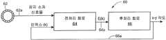
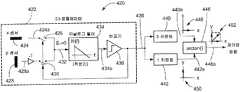
도 3을 참조하면, 자기장 센서(60)는 하나 이상의 자기장 감지 소자 신호들(62a)을 생성하는 CVH 감지 소자(62)를 포함한다. 전처리 회로(64)는 하나 이상의 자기장 감지 소자 신호들(62a)을 수신하도록 연결되고, 인덱스 값 신호(66a)를 수신하도록 연결되며, 인덱스 값 신호(66a)의 함수인 전처리 신호(64a)(또한, 여기서 신호 E(k)로 불림)를 생성한다. 후처리 회로(66)는 전처리 신호(64a)를 수신하도록 연결되고, 인덱스 값 신호(66a)에 상응하면서, 또한 CVH 감지 소자(62)가 배치된 x-y 평면에서 검출되는 자기장이 향하는 방향(또는 각도)을 나타내는 x-y 각도 신호에 상응하는 후처리 신호(66a)를 생성한다.Referring to FIG. 3, the
동작에 있어서, 후술되는 바에 의해 명확하게 될 바와 같이, 정지되고 비회전하는 자기장에 대하여, 회로(60)는, CVH 감지 소자(62)내의 복수의 수직 홀 소자들 모두가 계속하여 스캐닝하지 않고, CVH 감지 소자(62)내의 하나의 수직 홀 소자로부터의 샘플들을 가지는 자기장 감지 소자 신호(62a), 전처리 신호(64a)내의 상응하는 샘플들, 및 인덱스 값 신호(66a)내의 하나의 인덱스 값을 생성할 수 있다. 인덱스 값 신호(66a)의 값은 상기 감지된 자기장이 향하는 방향을 나타낸다. 다만, 인덱스 값 신호(66a)는, 예를 들어 노이즈 또는 상기 후처리 회로에서 이용되는 k를 업데이트하는 방법에 기인하여, 2 이상의 값들 사이를 교대할 수 있다. 도 2의 상기 수직 홀 소자 샘플들 모두를 생성하는 방식에 비하여, 상기 자기장의 각도의 보다 신속한 검출이 가능하다.In operation, for a stationary, non-rotating magnetic field, as will become clear by the following, the
동작에 있어서, 회전하는 자기장에 대하여, 회로(60)는, CVH 감지 소자(62)내의 복수의 수직 홀 소자들 모두를 계속하여 스캐닝하지 않고, CVH 감지 소자(62)내의 연속된 수직 홀 소자들로부터의 연속된 샘플들을 가지는 자기장 감지 소자 신호(62a), 전처리 신호(64a)내의 상응하는 샘플들, 및 인덱스 값 신호(66a)내의 연속된 인덱스 값들을 생성할 수 있다. In operation, for a rotating magnetic field, the
도 4를 참조하면, 예시적인 전처리 회로는 도 3의 전처리 회로(64)와 동일하거나 유사할 수 있다. 상기 전처리 회로는 제1 주파수를 가지는 클록 신호(80a)를 생성하는 발진기(80)를 포함한다. 분주기(82)는 클록 신호(80a)를 수신하도록 연결되고, 상기 제1 주파수보다 작은 제2 주파수를 가지는 분주된 클록 신호(82a)를 생성한다.4, an exemplary pre-processing circuit may be the same as or similar to the
상기 전처리 회로는, 클록 신호(80a)를 수신하도록 연결되고, 스위치 제어 신호들(84a)을 생성하는 스위치 제어 회로를 더 포함할 수 있다. 스위칭 회로(74)는 스위치 제어 신호들(84a)을 수신하도록 연결되고, 인덱스 값 신호(92b)를 수신하도록 연결되며, 인덱스 값 신호(92b)의 하나 이상의 인덱스 값들에 따라 처리를 위하여 CVH 감지 소자(72)의 수직 홀 소자들(73) 중 상응하는 하나 이상을 선택한다.The preprocessing circuit may further include a switch control circuit coupled to receive the
일 실시예에서, 인덱스 값 신호(92a)에 대하여 32 개의 가능한 값들이 존재하고, CVH 감지 소자(72)내에 32 개의 수직 홀 소자들이 존재한다. 그러나, 다른 실시예에서, 각각이 32 개보다 많거나 적을 수 있다. 일 실시예에서, 인덱스 값 신호(92a)의 가능한 값들의 수는 수직 홀 소자들의 수보다 적을 수 있다.In one embodiment, there are 32 possible values for the
일 실시예에서, 상기 전처리 회로는 스위치 제어 신호(84a)를 수신하도록 연결된 다른 스위칭 회로(76)를 더 포함할 수 있다. 스위칭 회로(76)는 CVH 감지 소자(72)내의 상기 수직 홀 소자들의 상술한 초핑을 수행할 수 있다.In one embodiment, the preprocessing circuit may further comprise another switching
기본적으로, 클록 신호(80a)는 초핑을 이용하는 실시예들에 대하여 상기 분주된 클록이 후처리 회로(92)를 구동하는 것보다 높은 주파수 클록으로 스위치 제어 회로(84)를 구동한다. 초핑이 이용되지 않는 경우, 스위칭 회로(76) 및 분주기(82)는 생략될 수 있고, 이 경우, 스위치 제어 회로(84) 및 후처리 회로(92)는 동일한 속도의 동일한 클록 신호로 동작할 수 있다.Basically, the
상기 전처리 회로는 인덱스 값 신호(92a)에 의해 선택되는 하나 이상의 수직 홀 소자들을 구동하도록 이용되는 구동 소스(78), 예를 들어 두 개의 전류 소스들을 더 포함할 수 있다. 전류 소스들 및 전압 소스들의 조합이 상기 구동 소스에 이용될 수 있고, 단일 홀 소자 또는 다중 홀 소자들을 동시에 구동할 수 있다.The preprocessing circuit may further comprise a
도 3을 참조하여 상술한 바와 같이, 후처리 회로(92)는 스위칭 회로들(74, 76)을 통하여 CVH 감지 소자(72)의 하나 이상의 자기장 감지 소자들로부터의 자기장 감지 소자 신호 샘플들(72a)을 수신하도록 연결되고, 하나 이상의 인덱스 값들을 가지는 인덱스 값 신호(92a)를 생성한다. 상기 후처리 회로는 또한 x-y 각도 신호(108a)를 생성하고, 이는 인덱스 값(108b)과 동일할 수 있으나, 여기서는 명확성을 위하여 별도로 도시되어 있다. 도 3을 참조하여 상술한 바와 같이 x-y 각도 신호(108a)는 상기 CVH 감지 소자가 배치된 x-y 평면에서의 자기장의 각도를 나타낸다.As discussed above with reference to FIG. 3, the
도 5를 참조하면, 도 4의 구성요소들과 유사한 구성요소들에는 유사한 참조번호로 표시되어 있고, 전처리 회로는 스위칭 회로들(74, 76)과 후처리 회로(108) 사이에 배치되게 도시된 다른 회로(102)를 포함한다.5, components similar to those of FIG. 4 are designated by like reference numerals, and the pre-processing circuit is shown as being disposed between the switching
회로(102)는, 스위칭 회로들(74, 76)을 통하여 CVH 감지 소자(72)의 복수의 자기장 감지 소자들로부터 자기장 감지 소자 신호 샘플들(112)을 (병렬적으로 또는 순차적으로) 수신하도록 연결되고, 하나 이상의 인덱스 값들을 가지는 인덱스 값 신호(92a)를 생성하는 조합 회로(combining circuit)(104)를 포함한다. 유사한 조합 회로가, 2011년 2월 25일자로 출원된 미국특허출원번호 제13/035,257호, "Circuit and Method for Processing Signals Generated by a Plurality of Sensors"에 도시 및 개시되어 있다.The
일 실시예에서, CVH 감지 소자(72)의 상기 복수의 자기장 감지 소자들로부터의 자기장 감지 소자 신호 샘플들(112)은 동시에, 즉 병렬적으로 생성된다. 이러한 구성은, 2011년 2월 25일자로 출원된 미국특허출원번호 제13/035,243호, "Circular Vertical Hall Magnetic Field Sensing Element and Method with a Plurality of Continuous Output Signals"에 도시 및 개시되어 있다. 그러나, 다른 실시예에서, CVH 감지 소자(72)의 상기 복수의 자기장 감지 소자들로부터의 자기장 감지 소자 신호 샘플들(112)은, 예를 들어 PCT특허출원번호 제PCT/EP2008/056517호에 개시된 바와 같이, 순차적으로 생성된다.In one embodiment, the magnetic field sensing
후처리 회로(108)는 조합 회로(104)로부터 전처리 신호(104a)를 수신하도록 연결된다.The
또한, 조합 회로(104)는 bn(k) 제어 신호 생성기(106)에 의해 생성되는 bn(k) 제어 신호들(106a)을 수신하도록 연결된다. bn(k) 제어 신호 생성기(106)는 후처리 회로(108)에 의해 생성되는 인덱스 값 신호(108b)를 수신하도록 연결된다.In addition, the
또한, 후처리 회로(108)는 도 4의 x-y 각도 신호(92a)와 동일하거나 유사할 수 있는 x-y 각도 신호(108a)를 생성한다. x-y 각도 신호(108a) 및 인덱스 값 신호(108b)는 동일한 신호일 수 있으나, 여기서는 명확성을 위하여 별도의 신호들로 도시되어 있다.The
회로(102)의 동작이 보다 상세히 후술된다. 다만, 여기서는 조합 회로(104)가 자기장 감지 소자 신호 샘플들(112) 중 복수의 신호 샘플들을 수신하여 전처리 출력 신호(104a)내의 하나(또는 그 이상의) 샘플을 생성하도록 이들을 조합한다는 것만 언급하더라도 충분할 것이다.The operation of the
도 6을 참조하면, 스위칭 회로는, 인덱스 값 신호(92b)의 값(k)에 응답하여 CVH 감지 소자(72)내의 N 개의 수직 홀 소자들에 의해 생성되는 x0 내지 xN 신호들 중 하나를 선택하도록 이용되는 도 4의 스위칭 회로(74)와 동일하거나 유사할 수 있다.6, the switching circuit is responsive to the value (k) of the
도 7을 참조하면, 조합 회로(130)는 도 5의 조합 회로(104)와 동일하거나 유사할 수 있다. 조합 회로(130)는, 각각이 도 5의 CVH 출력 신호들(112)(xn = x0 내지 xN-1) 중 하나를 수신하도록 연결된 복수의 스위칭 회로들(136a-136N)을 포함한다. 스위칭 회로들(136a-136N)은 또한, 각각이 도 5의 제어 신호들(106a)(b0(k) 내지 bN-1(k)) 중 하나를 수신하도록 연결된다.Referring to Fig. 7, the
도 7a를 참조하면, 선택적으로, 각각의 샘플 앤 홀드(sample and hold) 회로들(138)은 스위칭 회로들(136a-136N) 앞에 연결될 수 있다. 샘플 앤 홀드 회로들(138)은 도 4의 CVH 출력 신호들(112)이 순차적으로 생성되는 상술한 실시예들에서 이용될 수 있다. 이러한 실시예들에서, 순차적으로 샘플링되어 유지되는 샘플링된 신호들(x'0 내지 x'N-1)이 신호들(x0 내지 xN-1)을 대신하여 스위칭 회로들(136a-136N)에 제공된다.7A, alternatively, each of the sample and hold
또한, 도 5의 CVH 출력 신호들(112)이 지속적으로 생성되는 상술한 실시예들에서, 샘플 앤 홀드 회로들(138)이 필요하지 않을 수 있고, 신호들(x0 내지 xN-1)이 동시에 스위칭 회로들(136a-136N)에 제공될 수 있다.Also, in the embodiments described above in which the CVH output signals 112 of FIG. 5 are continuously generated, the sample and hold
스위칭 회로들(136a-136N)은 각각의 스위칭된 신호들(z0(k) 내지 zN-1(k))(예를 들어, 32 개의 스위칭된 신호들)을 생성한다. 합산 회로(134)는 스위칭된 신호들(z0(k) 내지 zN-1(k))을 수신하도록 연결되고, 도 5의 전처리 신호(104a)와 동일하거나 유사할 수 있는 조합된 신호(134a)를 생성한다.The switching circuit (136a-136N) generates the switching signals of each (z0 (k) toz N-1 (k)) ( e.g., a switching signal 32). The summing
동작에 있어서, 임의의 특정한 시간에서, 제어 신호들(b0(k) 내지 bN-1(k)) 중 일부는 하이 상태에 있고, 나머지들은 로우 상태에 있다. 스위칭 회로들(136a-136N)이 제어 신호들(b0(k) 내지 bN-1(k))의 각각의 상태들에 응답함으로써, CVH 출력 신호들(x0 내지 xN-1) 각각은, 각각의 제어 신호의 하나의 특정한 상태에 응답하여 각각의 스위칭 회로를 지날 때 반전되고, 상기 제어 신호의 다른 상태에 응답하여 반전되지 않는다. 이에 따라, 출력 신호들(z0(k) 내지 zN-1(k))이 생성되고, 이들은 도시된 바와 같이 차동 신호들이거나, 싱글엔드(single ended) 신호들일 수 있다.In operation, at any particular time, some of the control signals b0 (k) to bN-1 (k) are in a high state and others are in a low state. By responding to the switching circuits (136a-136N), each state of the control signals (b0 (k) tob N-1 (k)) , the CVH output signal (x0 to xN-1), respectively Are inverted when they pass each switching circuit in response to one particular state of the respective control signal and are not inverted in response to the other state of the control signal. Thus, output signals z0 (k) to zN-1 (k) are generated, which may be differential signals as shown, or single ended signals.
조합된 신호(134a)(E(k))가 기본적으로 신호들의 합, 즉 반전된 일부의 CVH 출력 신호들(x0 내지 xN-1)과 반전되지 않은 일부의 CVH 출력 신호들(x0 내지 xN-1)의 합인 것을 이해할 수 있을 것이다.The combined signal (134a) to (E (k)) is essentially the sum of the signals, i.e. the CVH output signal of the inverted portion (x0 to xN-1) and the non-inverted part of the CVH output signal (x0 XN-1 ). ≪ /RTI >
동작에 있어서, 제어 신호들(b0(k) 내지 bN-1(k))은 종종 상태를 변경한다. 제어 신호들(b0(k) 내지 bN-1(k))의 변경은 도 8을 참조하여 보다 상세히 후술될 것이다.In operation, the control signals b0 (k) to bN-1 (k) often change states. The change of the control signals b0 (k) to bN-1 (k) will be described in more detail below with reference to FIG.
도 8을 참조하면, 그래프들(152-158) 각각은 CVH 감지 소자 둘레의 수직 홀 소자 위치의 단위를 가지는 수평축, 및 도 7의 bn 제어 신호들(b0(k) 내지 bN-1(k)) 및 도 5의 bn 제어 신호들(106a)의 이진 상태(1(예를 들어, 하이) 또는 0(예를 들어, 로우)의 단위를 가지는 수직축을 가진다.8, each of the graphs 152-158 includes a horizontal axis having units of vertical Hall element positions around the CVH sensing element, and bn control signals b0 (k) to bN-1 (e.g., high) or a zero (e.g., low) unit of bn control signals 106a in FIG.
상술한 바와 같이, 수평축들에 의해 표시된 상기 홀 소자 위치들, 즉 N 개의 위치들은 하나의 수직 홀 소자(즉, 하나의 수직 홀 소자 콘택)의 단계들을 가지거나, 2 이상의 수직 홀 소자들(즉, 2 이상의 수직 홀 소자 콘택들)의 단계들을 가질 수 있다. 게다가, 상기 위치들은 초핑된 구성에서 사용될 때 홀 소자들의 각각의 그룹들의 위치들을 나타낼 수 있다.As noted above, the Hall element locations, i.e. N locations, indicated by the horizontal axes may have steps of one vertical Hall element (i.e., one vertical Hall element contact) or two or more vertical Hall elements , Two or more vertical Hall element contacts). In addition, the positions may indicate positions of respective groups of Hall elements when used in a chopped configuration.
상기 그래프들 각각은 서로 다른 시점에서의 제어 신호들(b0(k) 내지 bN-1(k))을 나타낸다. 예를 들어, 그래프(152)는, 인덱스 변수(k)의 제1 시점(또는 증가(increment) 0)에서 b0(0) 내지 bN/2-1(0)의 제어 신호들이 로우이고, bN/2(0) 내지 bN-1(0)의 제어 신호들이 하이인 것을 나타낸다.Each of the graphs represents control signals b0 (k) to bN-1 (k) at different points in time. For example, the
아래에 기입된 인덱스는 상기 CVH 감지 소자 둘레의 상기 수직 홀 소자(또는 수직 홀 소자 콘택들의 그룹)의 위치(n)를 나태내고, 이들은 0에서 N-1까지 N 개가 존재한다. 인덱스(k)는 제어 신호들(b0(k) 내지 bN-1(k))의 변화와 연결된 시간 증가를 나타낸다.The indices written below indicate the position (n) of the vertical Hall element (or group of vertical Hall element contacts) around the CVH sensing element, where there are N from 0 to N-1. The index k represents the time increase associated with the change of the control signals b0 (k) to bN-1 (k).
인덱스(k)의 0번째 증가에서, 제어 신호(b0(0))는 로우이고, k = 0으로 표현되는 특정한 시점에서 도 7의 스위칭 회로(136a)에 의해 수신되는 제어 신호이다. 이러한 로우 제어 신호(b0(0))는 스위칭 회로(136a)가 반전시키지 않도록 할 수 있고, 이에 따라 z0(0) = x0(0)이다. N/2의 수직 홀 소자 위치에서, 제어 신호(bN/2(0))는 하이이고, 이는 도 7의 스위칭 회로들 중 상응하는 하나가 반전시키도록 할 수 있고, 이에 따라 zN/2(0) = -xN/2(0)이다. 마지막 수직 홀 소자 위치, N-1에서, 상응하는 제어 신호(bN-1(0))는 하이이고, 이는 또한 도 7의 스위칭 회로(136N)가 반전시키도록 할 수 있고, 이에 따라 zN-1(0) = -xN-1(0)이다.In the zeroth increment of the index k, the control signal b0 (0) is low and is the control signal received by the
그래프들(154-158)은, 시간 인덱스(k)의 각 증가에서 제어 신호들(b0(k) 내지 bN-1(k))이 하나의 수직 홀 소자 위치만큼(즉, 하나의 수직 홀 소자 콘택만큼) 쉬프트되는 특정한 하나의 실시예를 나타낸다. 따라서, 그래프(154)를 참조하면, 인덱스(k)의 상기 1번째 증가에서, 도 7의 스위칭 회로(136a)에 의해 수신되는 제어 신호(b0(1))는 이제 하이이다. 하이 제어 신호(b0(1))는 스위칭 회로(136a)가 반전시키도록 할 수 있고, 이에 따라 z0(1) = -x0(1)이다. N/2의 수직 홀 소자 위치에서, 제어 신호(bN/2(1))는 이제 로우이고, 이는 도 7의 스위칭 회로들 중 상응하는 하나가 반전시키지 않도록 할 수 있고, 이에 따라 zN/2(1) = xN/2(1)이다. 마지막 수직 홀 소자 위치, N-1에서, 상응하는 제어 신호(bN-1(1))는 여전히 하이이고, 이는 도 7의 스위칭 회로(136N)가 반전시키도록 할 수 있고, 이에 따라 zN-1(1) = -xN-1(1)이다.The graphs 154-158 show that the control signals b0 (k) to bN-1 (k) at each increment of the time index k are shifted by one vertical Hall element position Lt; RTI ID = 0.0 > a < / RTI > Hall element contact). Thus, referring to
이와 유사하게, 그래프(156)를 참조하면, 인덱스(k)의 N/2 증가에서, 제어 신호(b0(N/2))는 하이이고, 이는 도 7의 스위칭 회로(136a)에 의해 수신되는 제어 신호이다. 하이 제어 신호(b0(N/2))는 스위칭 회로(136a)가 반전시키도록 할 수 있고, 이에 따라 z0(N/2) = -x0(N/2)이다. N/2의 수직 홀 소자 위치에서, 제어 신호(bN/2(N/2))는 로우이고, 이는 도 7의 스위칭 회로들 중 상응하는 하나가 반전시키지 않도록 할 수 있고, 이에 따라 zN/2(N/2) = xN/2(N/2)이다. 마지막 수직 홀 소자 위치, N-1에서, 상응하는 제어 신호(bN-1(N/2))는 이제 로우이고, 이는 도 7의 스위칭 회로(136N)가 반전시키지 않도록 할 수 있고, 이에 따라 zN-1(N/2) = -xN-1(N/2)이다.Similarly, referring to
끝으로, 그래프(158)를 참조하면, 인덱스(k)의 N-1 증가에서, 제어 신호(b0(N-1))는 이제 로우이고, 이는 스위칭 회로(136a)가 반전시키지 않도록 할 수 있고, 이에 따라 z0(N-1) = x0(N-1)이다. N/2의 수직 홀 소자 위치에서, 제어 신호(bN/2(N-1))는 이제 하이이고, 이는 도 7의 스위칭 회로들 중 상응하는 하나가 반전시키도록 할 수 있고, 이에 따라 zN/2(N-1) = -xN/2(N-1)이다. 마지막 수직 홀 소자 위치, N-1에서, 상응하는 제어 신호(bN-1(N-1))는 로우이고, 이는 도 7의 스위칭 회로(136N)가 반전시키지 않도록 할 수 있고, 이에 따라 zN-1(N-1) = -xN-1(N-1)이다.Finally, referring to
인덱스(k)의 임의의 증가에서 제어 신호들(b0(k) 내지 bN-1(k))의 절반이 하이이고 나머지가 로우인 것으로 도시되어 있으나, 다른 실시예에서, 다른 비율의 하이 및 로우 제어 신호들이 이용될 수 있다. 이는 절반의 비율에서 하나의 제어 신호만이 하나의 상태이고, 다른 제어 신호들 모두가 다른 상태인 비율까지를 모두 포함할 수 있다. 다만, 최적의 신호대 잡음비는 상기 비율이 절반일 때 획득될 수 있다.Although half of the control signals b0 (k) to bN-1 (k) are shown as being high and the remainder being low in any increment of the index k, in other embodiments, And row control signals may be used. This means that at half the rate, only one control signal is in one state, and all of the other control signals are all in a different state. However, the optimum signal-to-noise ratio can be obtained when the ratio is half.
여기에 사용되는 바와 같이, 구문 "대략적으로 절반(approximately half)"는 약 40 퍼센트 내지 약 60 퍼센트의 범위를 의미한다.As used herein, the phrase "approximately half" means in the range of about 40 percent to about 60 percent.
도 9를 참조하면, 그래프(200)는 CVH 소자 위치(n)의 단위를 가지는 수평축을 가진다. 그래프(200)는 또한 밀리볼트의 크기 단위를 가지는 수직축을 가진다. 수직 스케일은 4의 k 인덱스 값에 대하여 스위칭된 소자 신호들(z0(k) 내지 zN-1(k))(예를 들어, 도 7 참조)의 크기를 나타낸다. 밀리볼트 단위의 전압 단위가 도시되어 있으나, 사용되는 회로의 종류에 따라 상기 크기는 전압 단위이거나 전류 단위일 수 있다. 상기 4의 k 인덱스 값은 상기 bn 제어 신호들의 특정한 쉬프트를 나타낸다(예를 들어, 도 8 참조).Referring to FIG. 9,
단지 참고를 위하여, 사인파(204)가 도시되어 있고, 이는 도 2의 사인파(54)와 유사하다.For reference only, a
신호(206)는 상기 CVH 감지 소자 내의 32 개의 수직 홀 소자 위치들 각각으로부터의 스위칭된 소자 신호들(예를 들어, z0(4) 내지 zN-1(4))을 나타내고, 이러한 신호들은, 예를 들어 도 7의 합산 회로(134)에 의해 조합되기 전의 신호들을 나타낸다. 신호(206)를 도 2의 신호(52)와 비교하면, CVH 소자 위치 4에서부터 CVH 소자 위치 19까지, 신호(206)가 신호(52)와 동일한 반면, CVH 소자 위치들 20 내지 31 및 위치들 0 내지 3에서, 신호(206)가 신호(52)로부터 반전된 것을 이해할 수 있을 것이다. 천이들(transitions)(206a, 206b)이 명확하게 도시되어 있다.
신호(206)의 모든 크기들(단계들)이, 예를 들어 도 7의 합산 회로(134)에 의해 합산되면, 이러한 합은 0에 근접하는 것을 이해할 수 있을 것이다.It will be appreciated that if all the sizes (steps) of the
도 9a를 참조하면, 그래프(220)는 CVH 소자 위치(n)의 단위를 가지는 수평축을 가진다. 그래프(220)는 또한 밀리볼트의 크기 단위를 가지는 수직축을 가진다. 수직 스케일은 28의 k 인덱스 값에 대하여 스위칭된 소자 신호들(z0(k) 내지 zN-1(k))(예를 들어, 도 7 참조)의 크기를 나타낸다. 상기 28의 k 인덱스 값은 상기 bn 제어 신호들의 특정한 쉬프트를 나타낸다(예를 들어, 도 8 참조).Referring to FIG. 9A,
단지 참고를 위하여, 사인파(224)가 도시되어 있고, 이는 도 2의 사인파(54)와 유사하다.For reference only, a
신호(222)는 상기 CVH 감지 소자 내의 32 개의 수직 홀 소자 위치들 각각으로부터의 스위칭된 소자 신호들(예를 들어, z0(28) 내지 zN-1(28))을 나타내고, 이러한 신호들은, 예를 들어 도 7의 합산 회로(134)에 의해 조합되기 전의 신호들을 나타낸다. 신호(222)를 도 2의 신호(52)와 비교하면, CVH 소자 위치 28에서부터 CVH 소자 위치 31까지, 신호(222)가 신호(52)와 동일한 반면, CVH 소자 위치들 12 내지 27에서, 신호(222)가 신호(52)로부터 반전된 것을 이해할 수 있을 것이다.
신호(222)의 모든 크기들(단계들)이, 예를 들어 도 7의 합산 회로(134)에 의해 합산되면, 이러한 합은 최대값에 근접하는 것을 이해할 수 있을 것이다.It will be appreciated that if all the magnitudes (steps) of the
도 10을 참조하면, 그래프(240)는 인덱스 값(k)의 단위를 가지는 수평축을 가진다. 그래프(240)는 또한 밀리볼트의 크기 단위를 가지는 수직축을 가진다. 신호(242)는, 상기 b(n) 제어 신호들의 모든 N 개의 가능한 쉬프트들에 대하여, 합산된 신호, 예를 들어 도 5의 전처리 신호(104a) 또는 도 7의 조합된 신호(134a)를 나타낸다.Referring to FIG. 10,
단지 참고를 위하여, 사인파(244)가 도시되어 있다.For reference only, a
신호(242)를 도 9 및 도 9a의 신호들(206, 222)과 비교하면, 인덱스 값(k)이 4(예를 들어, 도 9 참조)일 때 신호(242)가 대략 0이고, 인덱스 값(k)이 28(예를 들어, 도 9a 참조)일 때 신호가 대략 최대값임을 알 수 있다.Comparing
소자 위치에서 소자 위치까지의 이상적인 사인파로부터의 전압 편차를 발생시키는 도 2, 도 9 및 도 9a의 신호들(52, 206, 222)의 오프셋 에러들이 도 10의 신호(242)에서 크게 감소된 것을 알 수 있다. 이는 도 7의 합산 회로(134)에 의한 합산으로 임의의 무작위적 오프셋 신호들이 평균화되는 것에 기인한다.The offset errors of the
도 2를 참조하여 상술한 바와 같이, 도 1의 자기장(16)이 향하는 방향, 즉 45도는 상기 4의 CVH 소자 위치에서의 신호(52)의 최대값에 따라 결정될 수 있다.As described above with reference to Fig. 2, the direction in which the
다시 도 10을 참조하면, 이와 달리, 도 1의 자기장(16)이 향하는 방향이 신호(242)의 (예를 들어, 4의 인덱스 값(k)에서의) 0 교차(zero crossing)(또는 다른 소정의 값의 교차)에 따라 결정될 수 있다. 두 개의 0 교차들, 즉 k=4 근처에서의 하나 및 k=20 근처에서의 하나가 존재한다. 양의 E(k)에서 음의 E(k)로의 음의 기울기를 가지는 0 교차가 상기 자기장이 향하는 방향에 상응한다. 신호(242)는 신호(52)에 비하여 보다 작은 무작위적 변동(random fluctuation)을 가지고, 따라서 이러한 각도 측정이 보다 정확할 수 있다.Referring again to FIG. 10, the direction in which the
신호(242)의 크기가 도 2의 신호의 크기보다 큰 것으로 도시되어 있다. 신호(242)의 보다 큰 크기는 상기 합산 회로, 예를 들어 도 7의 합산 회로(134)에 의해 신호들이 합산된 것에 기인한다. 신호(242)는 다음과 같이 표현될 수 있다.The magnitude of the

여기서,here,

k = bn 제어 신호 인덱스이며,k = bn control signal index,
A = 상기 CVH 감지 소자에 사용된 수직 홀 소자 위치들의 전체 수에 관련된 상수이다.A = a constant related to the total number of vertical Hall element locations used in the CVH sensing element.
신호(242)의 보다 높은 크기가 신호대 잡음비를 향상시킬 수 있음을 이해할 수 있을 것이다.It will be appreciated that a higher magnitude of the
상술한 수식으로부터,


신호(242)(즉, 도 5의 전처리 신호(104a))는, 후속하여, 상기 자기장의 상기 각도를 나타내는 소정의 값, 예를 들어 0을 교차하는 신호(242)의 값들 중 하나를 확인하도록, 도 5의 후처리 회로(108)에 의해 처리될 수 있다.The signal 242 (i.e., the
여기에 개시된 회로들 및 방법들이 예시적으로 CVH 감지 소자 내의 수직 홀 소자들로 도시되어 있으나, 상술한 바와 같이, 동일한 기술들이 복수의 임의의 종류의 감지 조자로부터의 신호들을 처리하는 데에 이용될 수 있는 것을 이해할 수 있을 것이다. 일 실시예에서, 상기 회로들 및 방법들은 상기 복수의 감지 소자들로부터의 신호들 중 최대 신호를 확인하는 데에 이용될 수 있다. 또한, 오프셋 신호 변동의 감소, 및 증폭과 처리 속도의 증가의 동일한 장점이 자기장 센서 감지 소자들뿐만 아니라 임의의 종류의 감지 소자들에 적용될 수 있다. 예를 들어, 동일한 기술들이 음향 신호를 감지하는 데에 이용되는 복수의 음향 감지 소자들에 적용될 수 있다.Although the circuits and methods disclosed herein are illustratively shown as vertical Hall elements in a CVH sensing element, as described above, the same techniques may be used to process signals from a plurality of any kind of sensing elements You can understand what you can do. In one embodiment, the circuits and methods may be used to identify a maximum signal among the signals from the plurality of sensing elements. In addition, the same advantages of reducing offset signal variations and increasing amplification and processing speed can be applied to any kind of sensing elements as well as magnetic field sensor sensing elements. For example, the same techniques can be applied to a plurality of acoustic sensing elements used to sense acoustic signals.
임의의 종류의 측정 장치들, 즉 임의의 종류의 감지 소자들 또는 센서들과 관련하여 동일한 이점들이 달성될 수 있는 것을 이해할 수 있을 것이다. 예를 들어, 동일한 기술들이, 각각이 자기장 감지 소자 및 연관된 처리 회로를 가지는 복수의 자기장 센서들에 적용될 수 있다.It will be appreciated that the same benefits can be achieved with respect to any kind of measuring devices, i. E. Any kind of sensing elements or sensors. For example, the same techniques can be applied to a plurality of magnetic field sensors, each having a magnetic field sensing element and associated processing circuitry.
도 7 및 도 7a를 참조하여 상술한 바와 같이, 여기에 개시된 CVH 감지 소자는 복수의 수직 홀 소자들로부터의 출력 신호들이 순차적으로 제공되는 모드, 또는 복수의 수직 홀 소자들로부터의 출력 신호들이 동시에 또한 연속하여 제공되는 모드에 사용될 수 있다. 순차적 구성은, 여기에 참조로 포함되는 PCT특허출원번호 제PCT/EP2008/056517호에 개시되어 있다. 연속적 구성은, 2011년 2월 25일자로 출원된 미국특허출원번호 제13/035,243호, "Circular Vertical Hall Magnetic Field Sensing Element and Method With a Plurality of Continuous Output Signals"에 개시되어 있다.As described above with reference to Figs. 7 and 7A, the CVH sensing element disclosed herein is a mode in which output signals from a plurality of vertical Hall elements are sequentially provided, or output signals from a plurality of vertical hall elements are simultaneously It can also be used in a continuously provided mode. Sequential construction is disclosed in PCT Patent Application No. PCT / EP2008 / 056517, which is incorporated herein by reference. The continuous configuration is disclosed in U.S. Patent Application Serial No. 13 / 035,243, filed February 25, 2011, entitled "Circular Vertical Hall Magnetic Field Sensing Element and Method with a Plurality of Continuous Output Signals".
도 11을 참조하면, 회로(260)는 후처리 회로(262b)에 연결된 전처리 회로(262a)를 포함한다. 전처리 회로(262a)는 도 3, 도 4 또는 도 5를 참조하여 상술한 전처리 회로 중 임의의 회로와 동일하거나 유사할 수 있다. 이와 유사하게, 후처리 회로(262b)는 도 3, 도 4 또는 도 5를 참조하여 상술한 후처리 회로들 중 하나와 동일하거나 유사할 수 있다.Referring to Fig. 11,
도 3을 참조하여 상술한 바와 같이, 전처리 회로(262a)는 감지 소자 신호들(264)(또는 보다 일반적으로, 측정 소자 신호들(264)), 예를 들어 자기장 감지 소자 신호들을 수신하도록 연결되고, 인덱스 값 신호(270a)를 수신하도록 연결되며, 전처리 신호(266a)를 생성한다. 후처리 회로(262b)는 전처리 신호(266a)를 수신하도록 연결되며, 인덱스 값 신호(270a)를 생성한다.As described above with reference to FIG. 3, the
전처리 회로(262a) 및 후처리 회로(262b)는 시그마 델타 모듈레이터(sigma delta modulator)와 유사한 구성으로 연결된다. 상기 후처리 회로는, 예를 들어 전처리 신호(266a)를 수신하도록 연결되고 적분된 신호(268a)를 생성하는 아날로그 필터(268)(적분기(integrator))를 포함할 수 있다. 또한, 후처리 회로(262b)는, 적분된 신호(268a)를 수신하도록 연결되고, 전처리 회로(262)에 의해 수신되는 인덱스 값 신호(270a)에 상응하고, 감지된 파라미터의 각도, 예를 들어 자기장의 각도를 나타내는 각도 출력 신호(270a)(즉, x-y 각도 신호)에 상응하는 변환된 신호(270a)를 생성하는 아날로그 디지털 변환기(270)를 더 포함할 수 있다.The
일 실시예에서, 인덱스 값 신호(270a)는 M 개의 디지털 비트들을 가진다. 그러나, 다른 실시예에서, 아날로그 디지털 변환기(270)는 간단한 형태의 아날로그 디지털 변환기인 비교기일 수 있다. 이러한 실시예에서, 인덱스 값 신호(270a)가 단지 하나의 디지털 비트를 가짐을 이해할 수 있을 것이다. 아날로그 디지털 변환기(270)로서 비교기가 이용되는 경우, 해상도를 증가시키기 위하여 상기 인덱스 값 신호가 CVH 전단 회로(262a)에 제공되기 전에 상기 결과적인 인덱스 값 신호가 평균화되는 것이 바람직할 것이다. 여기에 사용되는 바와 같이, 용어 "아날로그 디지털 변환기(analog-to-digital converter)"는 비교기를 포함하고, 또한 임의의 멀티-비트 아날로그 디지털 변환기를 포함한다.In one embodiment, the
일 실시예에서, 아날로그 필터(268)는 단일 적분기이고, 이에 따라 회로(260)는 1차 시그마-델타 변환기와 유사할 수 있다. 그러나, 임의의 수의 적분기들이 사용될 수 있고, 이에 따라 회로(260)는 1보다 큰 차수의 시그마-델타 변환기와 유사할 수 있다.In one embodiment, the
회로(260)의 동작이 도 11 및 도 12를 참조하여 후술된다.The operation of the
도 12를 참조하면, 그래프(280)는 도 11의 인덱스 값 신호(270a)의 값의 단위를 가지는 수평축을 가지고, 여기서 인덱스 값 신호(270a)는 5 비트 범위(32 개의 값들)를 가지는 것으로 가정된다. 각 인덱스 값이 CVH 감지 소자 내의 수직 홀 소자들 중 하나의 선택에 상응하는 것을 이해할 수 있을 것이다. 그래프(280)는 도 11의 전처리 신호(266a)의 임의의 크기 단위, 예를 들어 밀리볼트 단위를 가지는 수직축을 가진다. 그래프(280)는 예로서 데이터 포인트(282)를 포함하는 데이터 포인트들을 포함한다. 사인 곡선(284)은 상기 데이터 포인트들의 이상적인 형태를 나타내도록 도시되어 있다. 도 12에서는 오프셋 전압들이 도시되어 있지 않다.12, the
후술될 바와 같이, 정지된 자기장에 대하여, 도 11의 회로(260)는 순차적으로 또는 동시에 도 12에 도시된 상기 데이터 포인트들의 모두를 생성하지는 않는다. 즉, 회로(260)는 순차적으로 또는 동시에 상기 CVH 감지 소자 내의 수직 홀 소자들 모두를 선택하지는 않는다. 오히려, 정지된 자기장에 대하여, 회로(260)는 단지 상기 데이터 포인트들 중 하나, 즉 전처리 출력 신호(266a)의 하나의 값, 즉 상기 CVH 감지 소자 내의 하나의 선택된 수직 홀 소자(또는, 도 5, 및 도 7-10을 참조하여, 상기 CVH 감지 소자 내의 홀 효과 소자들의 하나의 부분 반전 및 합산)를 탐색하고, 상기 하나의 데이터 포인트는 회로(260)에 의해 감지된 상기 자기장의 방향을 나타낸다. 이는 아래의 예로서 후술될 것이다.As will be described below, for a stationary magnetic field, the
상기 데이터 포인트들을 참조하면, 수직 홀 소자 번호 12 및 번호 28(또는, 도 5, 및 도 7-10을 참조하여, 인덱스 값들 12 및 18을 가지는 부분 반전들 및 합산들)이 자기장에 가장 민감함을 이해할 수 있을 것이다. 따라서, 수직 홀 소자들 12 및 28, 더 정확히 말하면 수직 홀 소자들 12 및 28의 수직 홀 소자 콘택들을 구별하는 라인들이 상기 감지된 자기장에 거의 직교한다. 이와 유사하게, 수직 홀 소자들 4 및 20은 상기 자기장에 거의 평행하고, 거의 0의 출력을 생성한다. 다시 말해서, 상기 감지된 자기장이 향하는 방향은 자기장 감지 소자 번호 0에 대하여 45 도의 각도를 가진다.Referring to the data points, vertical
상기 회로, 예를 들어 도 11의 회로(260)는 초핑을 포함하거나 포함하지 않을 수 있다. 이와 유사하게, 도 12의 데이터 포인트들은 초핑을 나타내거나 나타내지 않을 수 있다.The circuit, for
도 12의 데이터 포인트들의 0 교차들은 상기 인덱스 값 신호, 즉 인덱스 값들(k)에 대하여 획득될 수 있는 두 개의 평균값들, 즉 정지된 자기장이 45 도를 향하는 예에 대하여 회로(260)에 의해 획득될 수 있는 4.5 및 20.5가 존재함을 나타낸다. 따라서, 회로(260)는, 임의의 정지된 자기장에 대하여 상기 자기장이 향하는 방향에 대하여 하나만이 정확한, 즉 모호한 결과들을 제공할 수 있다. 그러나, 후술되는 바로부터, 회로(260)가 4.5의 인덱스 값을 향하여 수렴하고, 20.5의 인덱스 값으로부터 발산하도록 동작하는 것을 이해할 수 있을 것이다.The zero crossings of the data points of FIG. 12 are obtained by the
상술한 모호성을 설명하기 위하여, 시간 t=0에서의 도 11의 적분된 신호(268a)가, 아날로그 디지털 변환기(270)로부터의 출력 신호, 즉 인덱스 값 신호(270a)의 인덱스 값이 도 12의 데이터 포인트 "a"에 상응하는 18과 같도록 하는 신호인 것으로 가정한다. 18의 인덱스 값에서, 도 11의 전처리 출력 신호(266a)는 음이다. 따라서, 도 11의 적분된 신호(268a)는 보다 음으로 향할 수 있고, 즉 도 11의 인덱스 값 신호(270a)의 인덱스 값을 감소시킬 수 있고, 전처리 출력 신호(266a) 및 도 12에 도시된 연관된 데이터 포인트들을 감소시킬 수 있다. 따라서, 인덱스 값 신호(270a)의 값이 포인트 "a"로부터 포인트 "b"를 향하여 이동하고, 결국에는 포인트들 "e" 및 "f" 사이에서 토글하면서 고정될 수 있다. 상기 회로가 데이터 포인트 "d"에 도달하면, 이는 다시 "e" 및 "f" 사이에서 토글하는 경향이 있다.To explain the ambiguity described above, the
상술한 예는 수렴하지만, 인덱스 값 신호(270a)의 동일한 최종 값으로의 수렴이 모든 시작 포인트로부터 발생하는 것은 아니다. 이는 도 13을 참조하여 도시 및 설명된다.The above example converges, but convergence of the
정지된 자기장들에 대하여 상술되었으나, 회전하는 자기장에 대하여, 상기 데이터 포인트들이 놓인 상기 사인 곡선의 위상이 회전할 것이라는 것을 이해할 수 있을 것이다. 이에 따라, 도 11의 회로(260)는 상기 데이터 포인트들의 0 교차(또는 임의의 원하는 소정의 값의 교차)를 나타내는 인덱스 값 신호(270a)의 새로운 값들을 찾는 것을 계속하여 시도할 것이다. 따라서, 회전하는 자기장에 대하여, 인덱스 값 신호(270a)는, 각각이 상기 데이터 포인트가 생성된 시점에서의 상기 자기장의 각도를 나타내는 새로운 값들을 계속하여 획득할 것이다.It will be appreciated that for a rotating magnetic field, the phase of the sinusoid on which the data points lie will rotate, as described above for stationary magnetic fields. Accordingly, the
도 13을 참조하면, 상술한 예에서, 다만 새로운 포인트 "a"=22에서 시작하는 경우, 상기 새로운 포인트 "a"에서 전처리 출력 신호(266a)는 양이다. 따라서, 도 11의 적분 신호(268a)는 더욱 양으로 향할 수 있다. 그러므로, 인덱스 값 신호(270a) 및 연관된 전처리 신호(266a)는 데이터 포인트들 "b" 및 "c"를 통하여 위로 이동할 것이고, 결국, 데이터 포인트 "d"에 고착(stuck)될 것이나, 이 데이터 포인트는 상기 자기장이 향하는 방향을 나타내지 않는다.Referring to Fig. 13, in the above example, when starting at the new point "a" = 22, the preprocessed
따라서, 도 11의 회로(260)가 일부 응용들에서 적절할 것이나, 일반적으로, 360 도로 회전하는 자기장의 회전을 감지하도록 CVH 감지 소자가 사용될 때, 다른 처리 회로들, 예를 들어 도 14 및 도 15를 참조하여 도시 및 후술될 회로들 및 기술들이 이용될 수 있다.Thus, when the CVH sensing element is used to sense rotation of a magnetic field that rotates 360 degrees, although the
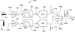
도 14를 참조하면, 회로(320)는 후처리 회로(322b)에 연결된 전처리 회로(322a)를 포함한다. 전처리 회로(322a)는 도 3, 도 4 또는 도 5를 참조하여 상술한 전처리 회로들 중 임의의 것과 동일 또는 유사할 수 있다. 이와 유사하게, 후처리 회로(322b)는 도 3, 도 4 및 도 5를 참조하여 상술한 후처리 회로들 중 하나와 동일 또는 유사할 수 있다.Referring to Fig. 14,
도 11의 후처리 회로(262b)와 달리, 후처리 회로(322b)는 상기 입력 자기장을 나타내지 않는 값에 고착(stuck)되지 않는다.Unlike the
전처리 회로(322a) 및 후처리 회로(322b)는 시그마 델타 모듈레이터와 유사한 구성으로 연결된다. 상기 후처리 회로는, 예를 들어 전처리 신호(326a)를 수신하도록 연결되고 적분된 신호(328a)를 생성하는 아날로그 필터(328)(적분기, 여기서 스위치드 커패시터 적분기(switched capacitor integrator)로 도시됨)를 포함할 수 있다. 또한, 후처리 회로(262b)는, 적분된 신호(328a)를 수신하도록 연결되고, 변환된 신호(332a)를 생성하는 아날로그 디지털 변환기(332)를 더 포함할 수 있다.The
도 11의 후처리 회로(262b)와 달리, 후처리 회로(322b)는, 변환된 신호(332a)를 수신하도록 연결되고, 전처리 회로(322a)에 의해 수신되는 인덱스 값 신호(334a)에 상응하고, 감지된 파라미터의 각도, 예를 들어 자기장의 각도를 나타낼 수 있는 각도 출력 신호(334a)(즉, x-y 각도 신호)에 상응하는 모듈로(modulo) 신호를 생성하는 모듈로 회로(334)를 포함할 수 있다.Unlike the
일 실시예에서, 회로(320)는, 인덱스 값 신호(334a)를 수신하도록 연결되고, 필터링된 출력 신호(336a)를 생성하는 다른 필터 회로, 예를 들어 데시메이션(decimation) 필터 회로(336)를 더 포함할 수 있다. 필터(336)는 CVH 감지 소자의 본래 특성에 의해 결정되는 인덱스 값(k)에 대한 선택의 수보다 큰 해상도를 제공하도록 출력들을 평균화하는 데에 이용될 수 있다. 출력 샘플들이 일반적으로 인덱스 값(k)에 대한 업데이트 속도만큼 빠를 필요가 없기 때문에 데시메이션 필터가 바람직할 수 있고, 필터(336)는 데시메이션 필터일 때 매우 간단해질 수 있다.
모듈로 회로(334)는 또한 소위 "초과 범위 신호(over-range signal)"(334b)를 생성할 수 있다. 또한 스위치드 커패시터들로 형성될 수 있는 가산기 회로(336)는 초과 범위 신호(334)를 수신하도록 연결될 수 있고, 스위치드 커패시터 필터 회로(328)로 합산되는 계단 신호(step signal)(322)를 생성할 수 있다.The modulo circuit 334 may also generate a so-called "over-range signal" 334b. An
일 실시예에서, 인덱스 값 신호(334a)는 (도 1의 인덱스 값 신호(270a)의 M 개의 비트들과 비교하여) M+1 개의 비트들을 가진다.In one embodiment, the
아날로그 디지털 변환기(332)의 범위는 도 11의 아날로그 디지털 변환기(270)의 범위보다 커서, 아날로그 디지털 변환기(332)는, 포화(saturating) 없이, 도 11의 정상 범위를 벗어나는 입력도 감지할 수 있다. 일 실시예에서, 아날로그 디지털 변환기(332)의 범위는 도 11의 아날로그 디지털 변환기(270)의 범위보다 하나의 비트만큼 클 수 있다. 그러나, 다른 실시예에서, 아날로그 디지털 변환기(332)의 범위는 도 11의 아날로그 디지털 변환기(270)의 범위보다 하나의 비트보다 작은 크기만큼, 또는 하나의 비트보다 큰 크기만큼 클 수 있다.The range of the analog to
일 실시예에서, 아날로그 필터(328)는 단일 적분기를 포함하고, 이에 따라 회로(320)는 1차 시그마-델타 변환기와 유사할 수 있다. 다만, 임의의 수의 적분기들이 사용될 수 있고, 이에 따라, 회로(320)는 1 차보다 큰 차수의 시그마-델타 변환기와 유사할 수 있다.In one embodiment, the
상기 모듈로 회로의 동작은 아래의 [표 1]로부터 이해될 수 있다.The operation of the modulo circuit can be understood from the following [Table 1].
필터링된 신호(328a)로부터 Vref를 가산 또는 감산하는 것은 인덱스 값 신호(334a)의 결과값(k)을 변경하지 않으나, 상기 가산 또는 감산은 적분된 신호(328a)가 한계 없이 증가하는 것을 방지할 수 있다.Adding or subtracting Vref from the filtered
회로(320)의 전체적인 동작이 도 15를 참조하여 후술된다.The overall operation of
도 15를 참조하면, 그래프(350)는 도 14의 인덱스 값 신호(334a)의 값의 단위를 가지는 수평축을 가지고, 여기서 인덱스 값 신호(334a)는 5 비트 범위(32 개의 값들)를 가지는 것으로 가정된다. 인덱스 값이 CVH 감지 소자 내의 수직 홀 소자들 중 하나의 선택(또는, 도 5 및 도 7-10에 따라, 상기 CVH 감지 소자 내의 홀 효과 소자들의 하나의 부분 반전 및 합산)에 상응하는 것을 이해할 수 있을 것이다. 그래프(350)는 도 14의 전처리 신호(326a)의 임의의 크기 단위, 예를 들어 밀리볼트 단위를 가지는 수직축을 가진다. 그래프(350)는 예로서 데이터 포인트(352)를 포함하는 데이터 포인트들을 포함한다. 사인 곡선(354)은 상기 데이터 포인트들의 이상적인 형태를 나타내도록 도시되어 있다. 도 15에서는 오프셋 전압들이 도시되어 있지 않다.Referring to FIG. 15,
도 3을 참조하여 상술한 바와 같이, 전처리 회로(322a)는 감지 신호들(324), 예를 들어 자기장 감지 소자 신호들을 수신하도록 연결되고, 인덱스 값 신호(334a)를 수신하도록 연결되며, 전처리 신호(326a)를 생성한다. 후처리 회로(322b)는 전처리 신호(326a)를 수신하도록 연결되고, 인덱스 값 신호(334a)를 생성한다.As described above with reference to Figure 3, the
상술한 또한 후술될 바로부터, 도 14의 회로(320)가, 정지된 자기장에 대하여, 순차적으로 또는 동시에 도 15에 도시된 데이터 포인트들 모두를 생성하지는 않고, 즉 회로(320)는 순차적으로 또는 동시에 상기 CVH 감지 소자 내의 모든 수직 홀 소자들을 선택하지 않는다. 오히려, 정지된 자기장에 대하여, 회로(320)는 상기 데이터 포인트들 중 단지 하나, 즉 전처리 출력 신호(326a) 중 하나의 값, 즉 상기 CVH 감지 소자 내의 하나의 선택된 수직 홀 소자를 탐색하고, 상기 하나의 데이터 포인트는 회로(320)에 의해 감지된 상기 자기장의 방향을 나타낸다. 이는 아래의 예로 후술된다.It will be appreciated from the foregoing, and hereinafter, that
상기 데이터 포인트들을 참조하면, 도 12 및 도 13의 그래프들에서와 유사하게, 수직 홀 소자 번호 12 및 번호 28(또는, 도 5, 및 도 7-10에 따라, 인덱스 값들 12 및 18을 가지는 부분 반전들 및 합산들)이 자기장에 가장 민감한 것을 이해할 수 있을 것이다. 따라서, 수직 홀 소자들 12 및 28이, 즉 더 정확히 말하면, 수직 홀 소자들 12 및 28의 수직 홀 소자 콘택들을 구별하는 라인들이 상기 감지된 상기 감지된 자기장에 거의 직교한다. 이와 유사하게, 수직 홀 소자들 4 및 20은 상기 자기장에 거의 평행하고, 거의 0의 출력을 생성한다. 다시 말해서, 상기 감지된 자기장이 향하는 방향은 자기장 감지 소자 번호 0에 대하여 45 도의 각도를 가진다.Referring to the data points, similar to the graphs of Figures 12 and 13, vertical
상기 회로, 예를 들어 도 14의 회로(320)는 초핑을 포함하거나, 포함하지 않을 수 있다. 이와 유사하게, 도 15의 상기 데이터 포인트들은 초핑을 나타내거나, 나타내지 않을 수 있다.The circuit, for
도 15의 상기 데이터 포인트들은 상기 인덱스 값 신호에 대하여 하나의 평균값이 있음, 즉 상기 정지된 자기장이 275도를 향하는 예에 대하여 회로(320)에 의해 획득되는 인덱스 값(k), 4.5(즉, k=4와 k=5의 포인트들 사이에서 토글링함)가 있음을 나타낸다. 따라서, 회로(320)는 임의의 정지된 자기장에 대하여 상기 자기장이 향하는 방향에 대한 모호하지 않은 결과를 제공할 수 있고, 도 13을 참조하여 상술한 바와 같이 잘못된 포인트에 "고착(stuck)"되지 않는다.The data points of FIG. 15 have an average value for the index value signal, i.e., the index value k obtained by the
상술한 향상된 동작을 설명하도록, 시간 t=0에서의 도 15의 적분된 신호(328a)가, 아날로그 디지털 변환기(332a)로부터의 상기 출력 신호가 도 13의 데이터 포인트 "a"와 유사한 도 15의 데이터 포인트 "a"에 상응하는 22가 되도록(즉, 수직 홀 소자 22가 선택됨) 하는 신호인 것으로 가정한다. 포인트 "a"에서, 전처리 출력 신호(326a)는 양이다. 따라서, 도 15의 적분된 신호(328a)는 더욱 양으로 향할 것이다. 그러므로, 변환된 신호(332a)는 데이터 포인트들 "b", "c"를 통하여 위로 이동할 것이고, 도 12의 데이터 포인트 "d"에 고착되지 않을 것이다. 대신에, [테이블 1]에 따라, 변환된 신호(332a)가 32의 값을 초과함에 따라, 초과 범위 신호(334b)는 필터 회로(328)에서 감산이 수행되도록 하여, 상기 데이터 포인트들이 "c"로부터 새로운 데이터 포인트 "d"로 점프하도록 할 것이다. 포인트 "d"에 위치하면, 상기 회로는 도 12를 참조하여 상술한 바와 같이 동작하고, 회로(320)는 포인트들 "e"와 "f" 사이의 토글 포인트를 탐색할 것이다.To illustrate the above-described improved operation, the
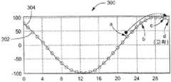
도 16을 참조하면, 그래프(370)는 도 14의 인덱스 값 신호(334a)의 샘플의 수에 상응하는 샘플 수 단위의 수평축을 포함한다. 또한, 그래프(370)는 회전 위치(k), 즉 인덱스 값 신호(334a)의 상기 수렴된 인덱스 값의 단위의 수직축을 포함한다.Referring to FIG. 16,
또한, 그래프(370)는 도 14의 인덱스 값 신호(334a)를 나타내는 신호(372)를 포함하고, 이는 일반적으로 후술되는 이유에 의해 4 와 5 사이의 값들 사이에서 토글링한다.
또한, 그래프(370)는 도 14의 필터링된 출력 신호(336a)를 나타내는 신호(374)를 포함하고, 이는 4.5의 값에 또는 근처에, 즉 인덱스 값 신호(372)에서 숫자 4의 발생 횟수와 숫자 5의 발생 횟수에 따른 정확한 값에 고정된다. 따라서, 도 14의 신호(336a)가, 예를 들어 데시메이션 필터(336a)와 같은 데시메이션 필터의 동작에 기인하여 인덱스 값 신호(334a)보다 작은 변동을 가지는 평탄화된 신호일 수 있다.The
도 17을 참조하면, 회로(390)는 x-축 자기장 센서(392)로부터 파생되는 x 채널 및 y-축 자기장 센서(402)로부터 파생되는 y 채널을 포함한다.17,
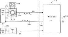
x-축 자기장 센서(392)는 자기장의 x 방향의 성분에 응답하여 자기장 신호(392a)를 생성한다. y-축 자기장 센서(402)는 상기 자기장의 상기 x 방향에 직교하는 y 방향의 성분에 응답하여 자기장 신호(302a)를 생성한다.The x-axis
상기 x 채널은 자기장 신호(392a)를 수신하도록 연결되고 증폭된 신호(394a)를 생성하는 증폭기(394)를 포함한다. 또한, 상기 x 채널은 증폭된 신호(394a)를 수신하도록 연결되고 필터링된 신호(396a)를 생성하는 필터 회로(396)를 더 포함한다. 또한, 상기 x 채널은 필터링된 신호(396a)를 수신하도록 연결되고 임의의 수의 비트들을 가지는 디지털 신호인 변환된 신호(398a)를 생성하는 아날로그 디지털 변환기(398)를 더 포함한다.The x channel includes an
이와 유사하게, 상기 y 채널은 자기장 신호(402a)를 수신하도록 연결되고 증폭된 신호(404a)를 생성하는 증폭기(404)를 포함한다. 또한, 상기 y 채널은 증폭된 신호(404a)를 수신하도록 연결되고 필터링된 신호(406a)를 생성하는 필터 회로(406)를 더 포함한다. 또한, 상기 y 채널은 필터링된 신호(406a)를 수신하도록 연결되고 임의의 수의 비트들을 가지는 디지털 신호인 변환된 신호(408a)를 생성하는 아날로그 디지털 변환기(408)를 더 포함한다.Similarly, the y channel includes an
아크탄젠트(arctangent) 회로(400)는 두 개의 변환된 신호들(398a, 408a)을 수신하도록 연결되고, x 센서(392) 및 y 센서(402)가 각각 감지하는 상기 x-y 평면에서의 상기 자기장이 향하는 방향을 나타내는 출력 신호(404a)로서 상기 두 개의 변환된 신호들의 아크탄젠트(arctangent)를 생성한다.The
그래프(410)는 변환된 신호(398a)를 나타내는 벡터를 가진다. 그래프(412)는 변환된 신호(408a)를 나타내는 벡터를 가진다. 그래프(414)는 변환된 신호들(398a, 408a)의 상기 아크탄젠트를 나타내는 벡터를 가진다.
도 18을 참조하면, 다른 회로(420)는 x-축 자기장 센서(424)로부터 파생되는 x 채널 및 y-축 자기장 센서(428)로부터 파생되는 y 채널을 포함한다.18, another
x-축 자기장 센서(424)는 자기장의 x 방향의 성분에 응답하여 자기장 신호(424a)를 생성한다. y-축 자기장 센서(428)는 상기 자기장의 상기 x 방향에 직교하는 y 방향의 성분에 응답하여 자기장 신호(428a)를 생성한다.The x-axis
회로(420)는 스위치들(426, 430)을 가지는 스위칭 회로를 포함한다. 상기 스위칭 회로는 자기장 신호(424a) 및 자기장 신호(428a)의 반전된 신호를 수신하도록 연결된다. 스위치들(426, 430)이 교대로 동작하여, 도 3의 전처리 신호(64a)와 유사한 신호(432)가 생성될 수 있다. 스위치들(426, 430)이 도 3의 전처리 회로(64)와 유사하고, 또한 도 6의 스위칭 회로와 유사한 것을 이해할 수 있을 것이다.
또한, 회로(420)는 신호(432)를 수신하도록 연결되고 적분된 신호(434a)를 생성하는 필터 회로(434)를 더 포함한다. 비교기(436)는 적분된 신호(434a)를 수신하도록 연결되고, 비교 신호(438)를 생성한다. 스위치들(426, 430)은 비교 신호(438)를 수신하도록 연결된다. 비교 신호(438)는 도 3의 인덱스 값 신호(66a)와 유사하거나, 도 4의 인덱스 값 신호(92b)와 유사하다.The
회로부(422)가 도 11의 회로부(262)와 유사한 것을 알 수 있을 것이다. 0 카운트 회로(438) 및 1 카운트 회로(442)가 비교 신호(438)를 수신하도록 연결된다. 상기 0 카운트 회로(440)는 소정의 시간 구간에서 비교 신호(438) 내의 0들의 횟수를 나타내는 신호(440a)를 생성한다. 이와 유사하게, 상기 1 카운트 회로(442)는 상기 소정의 시간 구간에서 비교 신호(438) 내의 1들의 횟수를 나타내는 신호(442a)를 생성한다.It will be appreciated that the
아크탄젠트 회로(446)는 신호들(440a, 442a)을 수신하도록 연결되고, x 센서(424) 및 y 센서(428)가 각각 감지하는 상기 x-y 평면에서의 상기 자기장이 향하는 방향을 나타내는 출력 신호(446a)로서 상기 두 개의 신호들의 아크탄젠트를 생성한다.The
회로(420)가 신호(438)로부터 값들을 선택하도록 동작함으로써, 시간이 지남에 따라, 신호(432)의 평균이 0이 되는 것을 이해할 수 있을 것이다. 상기 1의 횟수에 의해 나눠진 상기 0의 횟수의 상기 아크탄젠트는 상기 입력 각도를 나타내고, 이러한 각도는 0도와 90도 사이에 위치한다. 다른 스위칭 구성들 및 다른 유사한 회로들이 90도에서 360도의 각도들을 분석하도록 사용될 수 있다.It will be appreciated that as
그래프(448)는 신호(440a)의 값을 나타내는 벡터를 가진다. 그래프(450)는 신호(442a)의 값을 나타내는 벡터를 가진다. 그래프(452)는 신호들(440a, 442a)의 상기 아크탄젠트를 나타내는 벡터를 가진다.
도 17 및 도 18의 회로들(390, 420) 각각이, 지표면에 접하는(tangent) 평면에서, 또는 임의의 다른 평면에서, 지구 자기장의 방향을 나타내는 데에 사용되는 콤파스(compass) 회로들을 제공할 수 있다.Each of the
도 18의 회로(420)는 도 17의 회로(390)에 비하여 장점을 가진다. 즉, 도 17의 회로(390)는 두 개의 신호 경로들을 가지고, 이들은 정확성을 위하여 게인 및 위상이 매칭되어야 하므로, 보다 복잡한 회로를 가진다. 반면에, 도 18의 회로(420)는 공유되는 신호 경로를 가짐으로써, 상기 x 및 y 센서들의 측정에서의 발생 가능한 미스매치를 제거할 수 있다.The
회로들(390, 420)이 자기장 감지 소자들을 가지는 것으로 도시되어 있으나, 회로들(390, 420)은 임의의 종류의 감지 소자들과 함께, 또는 지향성(directional) 응답들을 가지는 임의의 종류의 측정 장치들과 함께 사용될 수 있다. 시그마-델타 변환기와 유사한 것으로 기재된 회로 토폴로지(topology)를 사용하는 회로들 및 기술들이 상술되었으나, 도 3-5, 도 11, 도 14, 도 17 및 도 18을 참조하여 상술한 인덱스 값 신호들과 유사한 인덱스 값 신호를 생성할 수 있거나, 상기 인덱스 값 신호를 생성하는 아날로그 디지털 변환기를 가지는 다른 회로 토폴로지들이 사용될 수 있음을 이해할 수 있을 것이다. 일 실시예에서, 상기 디지털 아날로그 변환기는 하나의 비트 출력을 가지는 비교기일 수 있다.Although
여기에 인용된 모든 문헌들은 이들 전체로서 여기에 참조로 포함된다.All documents cited herein are incorporated herein by reference in their entirety.
바람직한 실시예들에 대하여 상술하였으나, 이들은 본 특허에 대한 다양한 개념들, 구조들 및 기술들을 예시하도록 기재된 것이고, 본 발명이 속하는 기술분야의 통상의 지식을 가진 자들은 이러한 개념들, 구조들 및 기술들을 포함하는 다른 실시예들이 사용될 수 있음을 이해할 수 있을 것이다. 이에 따라, 본 특허의 범위는 상술한 실시예들로 한정되지 않고, 하기의 특허청구범위에 기재된 본 발명의 사상 및 영역에 의해서만 한정되어야 할 것이다.While the preferred embodiments have been described above, it will be understood by those skilled in the art that various changes may be made to these concepts, structures, and techniques Those skilled in the art will appreciate that other embodiments may be used, including those described herein. Accordingly, the scope of the present patent is not limited to the above-described embodiments, but should be limited only by the spirit and scope of the present invention described in the following claims.
Claims (35)
Translated fromKorean상기 복수의 측정 장치 신호들을 나타내는 신호를 수신하고, 상기 복수의 측정 장치들 중 하나 이상의 측정 장치의 선택을 나타내는 인덱스 값을 수신하며, 상기 인덱스 값에 따라 선택되는 상기 복수의 측정 장치 신호들 중 선택된 하나 이상을 나타내는 제1 전처리 출력 신호, 또는 상기 인덱스 값에 따라 선택되는 상기 복수의 측정 장치 신호들을 나타내는 신호들의 선택된 세트의 합을 나타내는 제2 전처리 출력 신호를 생성하는 전처리(preprocessing) 회로; 및
상기 제1 또는 제2 전처리 출력 신호를 수신하고, 상기 제1 또는 제2 전처리 출력 신호의 소정의 값 교차(crossing)를 상기 인덱스 값에 연관짓는 후처리(post processing) 회로를 포함하고,
상기 소정의 값 교차는 상기 감지된 파라미터의 상기 방향의 상기 각도를 나타내고,
상기 후처리 회로는,
상기 제1 또는 제2 전처리 출력 신호를 나타내는 신호를 수신하고, 상기 인덱스 값에 상응하는 디지털 변환된 신호를 생성하는 아날로그-디지털 변환기를 포함하는 것을 특징으로 하는 전자 회로.A plurality of measurement devices each for generating a plurality of measurement device signals having a magnitude related to an angle of a direction of a sensed parameter;
Receiving a signal representative of the plurality of measurement device signals, receiving an index value representative of a selection of one or more of the plurality of measurement devices, selecting one of the plurality of measurement device signals selected in accordance with the index value A preprocessing circuit for generating a second pre-processing output signal representing a sum of a first preprocessed output signal representing one or more, or a selected set of signals representing the plurality of measuring device signals selected in accordance with the index value; And
And post processing circuitry for receiving the first or second pre-processing output signal and associating a predetermined value crossing of the first or second pre-processing output signal with the index value,
The predetermined value intersection representing the angle of the direction of the sensed parameter,
The post-
And an analog-to-digital converter for receiving the signal indicative of the first or second pre-processing output signal and for generating a digitally converted signal corresponding to the index value.
상기 제1 또는 제2 전처리 출력 신호를 수신하고, 적분 신호를 생성하는 적분기(integrator)를 더 포함하고,
상기 아날로그-디지털 변환기는 상기 적분 신호를 수신하고, 상기 적분 신호에 따라 상기 디지털 변환된 신호를 생성하는 것을 특징으로 하는 전자 회로.The method according to claim 1,
Further comprising an integrator for receiving the first or second pre-processing output signal and generating an integral signal,
Wherein the analog-to-digital converter receives the integrated signal and generates the digitally converted signal according to the integrated signal.
상기 디지털 변환된 신호를 수신하고, 상기 감지된 파라미터의 상기 방향의 상기 각도를 나타내는 디지털 필터링된 신호를 제공하도록 상기 디지털 변환된 신호를 필터링하는 디지털 필터를 더 포함하는 것을 특징으로 하는 전자 회로.3. The apparatus of claim 2, wherein the post-
Further comprising a digital filter for receiving the digitally converted signal and filtering the digitally converted signal to provide a digitally filtered signal indicative of the angle of the direction of the sensed parameter.
상기 디지털 변환된 신호를 수신하고, 시간 구간 내에 상기 디지털 변환된 신호의 최하위 비트에서의 0 및 1의 발생 횟수들에 각각 상응하는 제1 및 제2 카운트 값들을 생성하는 카운트 회로; 및
상기 제1 카운트 값을 상기 제2 카운트 값에 비교하고, 상기 감지된 파라미터의 상기 방향의 상기 각도를 나타내는 카운트 비교 값을 생성하는 비교 회로를 더 포함하는 것을 특징으로 하는 전자 회로.3. The apparatus of claim 2, wherein the post-
A count circuit for receiving the digitally converted signal and generating first and second count values respectively corresponding to the number of occurrences of 0 and 1 in the least significant bit of the digitally converted signal in a time interval; And
Further comprising a comparison circuit that compares the first count value to the second count value and generates a count comparison value that indicates the angle of the sensed parameter in the direction.
상기 제1 또는 제2 전처리 출력 신호를 수신하고, 적분 신호를 생성하는 적분기(integrator), -상기 아날로그-디지털 변환기는 상기 적분 신호를 수신하고, 상기 적분 신호에 따라 상기 디지털 변환된 신호를 멀티-비트 디지털 변환된 신호로 생성함-; 및
상기 멀티-비트 디지털 변환된 신호를 수신하고, 상기 멀티-비트 디지털 변환된 신호가 소정의 값 범위 내인지 또는 초과하는지에 따라 상기 멀티-비트 디지털 변환된 신호에 대하여 소정의 값을 각각 가산 또는 감산하며, 상기 인덱스 값에 상응하는 멀티-비트 디지털 모듈로(modulo) 신호를 생성하는 모듈로 회로를 더 포함하는 것을 특징으로 하는 전자 회로.The method according to claim 1,
An integrator that receives the first or second pre-processing output signal and generates an integral signal, the analog-to-digital converter receives the integrated signal and outputs the digitally converted signal to a multi- Bit digital converted signal; And
Converting the multi-bit digitally converted signal to a predetermined value or adding or subtracting a predetermined value to the multi-bit digitally converted signal according to whether the multi-bit digitally converted signal is within a predetermined value range or not, Further comprising a modulo circuit for generating a multi-bit digital modulo signal corresponding to the index value.
상기 멀티-비트 디지털 모듈로 신호를 수신하고, 상기 감지된 파라미터의 상기 방향의 상기 각도를 나타내는 디지털 필터링된 신호를 제공하도록 상기 멀티-비트 디지털 모듈로 신호를 필터링하는 디지털 필터를 더 포함하는 것을 특징으로 하는 전자 회로.7. The image processing apparatus according to claim 6,
And a digital filter for filtering the signal to the multi-bit digital module to receive a signal with the multi-bit digital module and to provide a digitally filtered signal representing the angle of the direction of the sensed parameter .
상기 감지된 파라미터는 자기장인 것을 특징으로 하는 전자 회로.The apparatus of claim 1, wherein the plurality of measurement devices comprises a plurality of vertical Hall elements arranged in a circular vertical Hall (CVH) device structure above a common implant region in a common substrate,
Wherein the sensed parameter is a magnetic field.
상기 제1 또는 제2 전처리 출력 신호를 수신하고, 적분 신호를 생성하는 적분기(integrator)를 더 포함하고,
상기 아날로그-디지털 변환기는 상기 적분 신호를 수신하고, 상기 적분 신호에 따라 상기 디지털 변환된 신호를 생성하는 것을 특징으로 하는 전자 회로.10. The method of claim 9,
Further comprising an integrator for receiving the first or second pre-processing output signal and generating an integral signal,
Wherein the analog-to-digital converter receives the integrated signal and generates the digitally converted signal according to the integrated signal.
상기 디지털 변환된 신호를 수신하고, 상기 자기장의 상기 방향의 상기 각도를 나타내는 디지털 필터링된 신호를 제공하도록 상기 디지털 변환된 신호를 필터링하는 디지털 필터를 더 포함하는 것을 특징으로 하는 전자 회로.11. The apparatus of claim 10, wherein the post-
Further comprising a digital filter for receiving the digitally converted signal and filtering the digitally converted signal to provide a digitally filtered signal representing the angle of the direction of the magnetic field.
상기 제1 또는 제2 전처리 출력 신호를 수신하고, 적분 신호를 생성하는 적분기(integrator), -상기 아날로그-디지털 변환기는 상기 적분 신호를 수신하고, 상기 적분 신호에 따라 상기 디지털 변환된 신호를 멀티-비트 디지털 변환된 신호로 생성함-; 및
상기 멀티-비트 디지털 변환된 신호를 수신하고, 상기 멀티-비트 디지털 변환된 신호가 소정의 값 범위 내인지 또는 초과하는지에 따라 상기 멀티-비트 디지털 변환된 신호에 대하여 소정의 값을 각각 가산 또는 감산하며, 상기 인덱스 값에 상응하는 멀티-비트 디지털 모듈로(modulo) 신호를 생성하는 모듈로 회로를 더 포함하는 것을 특징으로 하는 전자 회로.10. The method of claim 9,
An integrator that receives the first or second pre-processing output signal and generates an integral signal, the analog-to-digital converter receives the integrated signal and outputs the digitally converted signal to a multi- Bit digital converted signal; And
Converting the multi-bit digitally converted signal to a predetermined value or adding or subtracting a predetermined value to the multi-bit digitally converted signal according to whether the multi-bit digitally converted signal is within a predetermined value range or not, Further comprising a modulo circuit for generating a multi-bit digital modulo signal corresponding to the index value.
상기 멀티-비트 디지털 모듈로 신호를 수신하고, 상기 자기장의 상기 방향의 상기 각도를 나타내는 디지털 필터링된 신호를 제공하도록 상기 멀티-비트 디지털 모듈로 신호를 필터링하는 디지털 필터를 더 포함하는 것을 특징으로 하는 전자 회로.14. The apparatus of claim 13, wherein the post-
Further comprising a digital filter for receiving the signal with the multi-bit digital module and filtering the signal to the multi-bit digital module to provide a digitally filtered signal representative of the angle in the direction of the magnetic field Electronic circuit.
상기 감지된 파라미터는 자기장인 것을 특징으로 하는 전자 회로.The apparatus of claim 1, wherein the plurality of measurement devices include a plurality of magnetic field sensing elements,
Wherein the sensed parameter is a magnetic field.
상기 복수의 측정 장치 신호들은 상기 자기장의 방향의 각도에 응답하여 생성되는 것을 특징으로 하는 전자 회로.17. The electronic device according to claim 16, wherein the electronic circuit is disposed on a common substrate,
Wherein the plurality of measurement device signals are generated in response to an angle of a direction of the magnetic field.
각각이 감지된 파라미터의 방향의 각도와 관련된 크기를 가지는 상기 복수의 측정 장치 신호들을 나타내는 신호를 수신하는 단계;
상기 복수의 측정 장치들 중 하나 이상의 측정 장치의 선택을 나타내는 인덱스 값을 수신하는 단계;
상기 인덱스 값에 따라 선택되는 상기 복수의 측정 장치 신호들 중 선택된 하나 이상을 나타내는 제1 전처리 출력 신호, 또는 상기 인덱스 값에 따라 선택되는 상기 복수의 측정 장치 신호들을 나타내는 신호들의 선택된 세트의 합을 나타내는 제2 전처리 출력 신호를 생성하는 단계; 및
상기 제1 또는 제2 전처리 출력 신호의 소정의 값 교차(crossing)를 상기 인덱스 값에 연관짓는 단계를 포함하고,
상기 소정의 값 교차는 상기 감지된 파라미터의 상기 방향의 상기 각도를 나타내고,
상기 연관짓는 단계는,
아날로그-디지털 변환기가 상기 인덱스 값에 상응하는 디지털 변환된 신호를 생성하도록 상기 제1 또는 제2 전처리 출력 신호를 나타내는 신호를 변환하는 단계; 및
상기 인덱스 값을 수신하는 단계에 상기 인덱스 값을 피드백하는 단계를 포함하는 것을 특징으로 하는 측정 장치 신호 처리 방법.A method for processing a plurality of measurement device signals generated by a plurality of measurement devices,
Receiving a signal representative of the plurality of measurement device signals each having a magnitude related to an angle of a direction of a sensed parameter;
Receiving an index value representative of a selection of one or more of the plurality of measurement devices;
A first pre-processing output signal representative of a selected one or more of the plurality of measurement device signals selected in accordance with the index value, or a sum of a selected set of signals indicative of the plurality of measurement device signals selected in accordance with the index value Generating a second pre-processing output signal; And
And associating a predetermined value crossing of the first or second pre-processing output signal with the index value,
The predetermined value intersection representing the angle of the direction of the sensed parameter,
Wherein the associating comprises:
Converting the signal representing the first or second pre-processing output signal so that the analog-to-digital converter generates a digitally converted signal corresponding to the index value; And
And feedbacking the index value to the step of receiving the index value.
적분 신호를 생성하도록 상기 제1 또는 제2 전처리 출력 신호를 적분하는 단계를 더 포함하고,
상기 변환하는 단계는,
상기 디지털 변환된 신호를 생성하도록 상기 적분 신호를 변환하는 단계를 포함하는 것을 특징으로 하는 측정 장치 신호 처리 방법.20. The method of claim 19,
Further comprising integrating said first or second pre-processing output signal to produce an integral signal,
Wherein the converting comprises:
And converting the integrated signal to produce the digitally converted signal.
상기 감지된 파라미터의 상기 방향의 상기 각도를 나타내는 디지털 필터링된 신호를 제공하도록 상기 디지털 변환된 신호를 디지털 필터링하는 단계를 더 포함하는 것을 특징으로 하는 측정 장치 신호 처리 방법.21. The method of claim 20,
Further comprising digitally filtering the digitally converted signal to provide a digitally filtered signal representing the angle of the direction of the sensed parameter.
시간 구간 내에 상기 디지털 변환된 신호의 최하위 비트에서의 0의 발생 횟수들에 상응하는 제1 카운트 값을 생성하는 단계;
상기 시간 구간 내에 상기 디지털 변환된 신호의 상기 최하위 비트에서의 1의 발생 횟수들에 상응하는 제2 카운트 값을 생성하는 단계; 및
상기 감지된 파라미터의 상기 방향의 상기 각도를 나타내는 카운트 비교 값을 생성하도록 상기 제1 카운트 값을 상기 제2 카운트 값에 비교하는 단계를 더 포함하는 것을 특징으로 하는 측정 장치 신호 처리 방법.21. The method of claim 20,
Generating a first count value corresponding to the number of occurrences of zeros in the least significant bit of the digitally converted signal within a time interval;
Generating a second count value corresponding to the number of occurrences of 1 in the least significant bit of the digitally converted signal within the time interval; And
Further comprising comparing the first count value to the second count value to produce a count comparison value representing the angle in the direction of the sensed parameter.
적분 신호를 생성하도록 상기 제1 또는 제2 전처리 출력 신호를 적분하는 단계, -상기 변환하는 단계는, 상기 디지털 변환된 신호를 멀티-비트 디지털 변환된 신호로 생성하도록 상기 적분 신호를 변환하는 단계를 포함함-; 및
상기 인덱스 값에 상응하는 멀티-비트 디지털 모듈로(modulo) 신호를 생성하도록, 상기 멀티-비트 디지털 변환된 신호가 소정의 값 범위 내인지 또는 초과하는지에 따라 상기 멀티-비트 디지털 변환된 신호에 대하여 소정의 값을 각각 가산 또는 감산하는 단계를 더 포함하는 것을 특징으로 하는 측정 장치 신호 처리 방법.20. The method of claim 19,
Integrating the first or second preprocessed output signal to produce an integrated signal, the step of converting includes converting the integrated signal to generate a multi-bit digitally converted signal Included -; And
Wherein the multi-bit digitally converted signal is generated by multiplying the multi-bit digitally converted signal according to whether the multi-bit digitally converted signal is within a predetermined value range or not so as to generate a multi-bit digital modulo signal corresponding to the index value And adding or subtracting a predetermined value, respectively, to the measurement signal.
상기 감지된 파라미터의 상기 방향의 상기 각도를 나타내는 디지털 필터링된 신호를 제공하도록 상기 멀티-비트 디지털 모듈로 신호를 디지털 필터링하는 단계를 더 포함하는 것을 특징으로 하는 측정 장치 신호 처리 방법.25. The method of claim 24,
Further comprising digitally filtering the signal to the multi-bit digital module to provide a digitally filtered signal representing the angle of the direction of the sensed parameter.
상기 감지된 파라미터는 자기장인 것을 특징으로 하는 측정 장치 신호 처리 방법.20. The apparatus of claim 19, wherein the plurality of measurement devices comprises a plurality of vertical Hall elements arranged in a circular vertical Hall (CVH) device structure above a common implant region in a common substrate,
Wherein the sensed parameter is a magnetic field.
적분 신호를 생성하도록 상기 제1 또는 제2 전처리 출력 신호를 적분하는 단계를 더 포함하고,
상기 변환하는 단계는,
상기 디지털 변환된 신호를 생성하도록 상기 적분 신호를 변환하는 단계를 포함하는 것을 특징으로 하는 측정 장치 신호 처리 방법.28. The method of claim 27,
Further comprising integrating said first or second pre-processing output signal to produce an integral signal,
Wherein the converting comprises:
And converting the integrated signal to produce the digitally converted signal.
상기 자기장의 상기 방향의 상기 각도를 나타내는 디지털 필터링된 신호를 제공하도록 상기 디지털 변환된 신호를 디지털 필터링하는 단계를 더 포함하는 것을 특징으로 하는 측정 장치 신호 처리 방법.29. The method of claim 28,
Further comprising digitally filtering the digitally converted signal to provide a digitally filtered signal indicative of the angle in the direction of the magnetic field.
적분 신호를 생성하도록 상기 제1 또는 제2 전처리 출력 신호를 적분하는 단계, -상기 변환하는 단계는, 상기 디지털 변환된 신호를 멀티-비트 디지털 변환된 신호로 생성하도록 상기 적분 신호를 변환하는 단계를 포함함-; 및
상기 인덱스 값에 상응하는 멀티-비트 디지털 모듈로(modulo) 신호를 생성하도록, 상기 멀티-비트 디지털 변환된 신호가 소정의 값 범위 내인지 또는 초과하는지에 따라 상기 멀티-비트 디지털 변환된 신호에 대하여 소정의 값을 각각 가산 또는 감산하는 단계를 더 포함하는 것을 특징으로 하는 측정 장치 신호 처리 방법.28. The method of claim 27,
Integrating the first or second preprocessed output signal to produce an integrated signal, the step of converting includes converting the integrated signal to generate a multi-bit digitally converted signal Included -; And
Wherein the multi-bit digitally converted signal is generated by multiplying the multi-bit digitally converted signal according to whether the multi-bit digitally converted signal is within a predetermined value range or not so as to generate a multi-bit digital modulo signal corresponding to the index value And adding or subtracting a predetermined value, respectively, to the measurement signal.
상기 자기장의 상기 방향의 상기 각도를 나타내는 디지털 필터링된 신호를 제공하도록 상기 멀티-비트 디지털 모듈로 신호를 디지털 필터링하는 단계를 더 포함하는 것을 특징으로 하는 측정 장치 신호 처리 방법.32. The method of claim 31,
Further comprising digitally filtering the signal to the multi-bit digital module to provide a digitally filtered signal indicative of the angle in the direction of the magnetic field.
상기 감지된 파라미터는 자기장인 것을 특징으로 하는 측정 장치 신호 처리 방법.20. The apparatus of claim 19, wherein the plurality of measurement devices include a plurality of vertical Hall elements,
Wherein the sensed parameter is a magnetic field.
Applications Claiming Priority (3)
| Application Number | Priority Date | Filing Date | Title |
|---|---|---|---|
| US13/113,603 | 2011-05-23 | ||
| US13/113,603US8860410B2 (en) | 2011-05-23 | 2011-05-23 | Circuits and methods for processing a signal generated by a plurality of measuring devices |
| PCT/US2012/034892WO2012161912A2 (en) | 2011-05-23 | 2012-04-25 | Circuits and methods for processing a signal generated by a plurality of measuring devices |
Publications (2)
| Publication Number | Publication Date |
|---|---|
| KR20140032401A KR20140032401A (en) | 2014-03-14 |
| KR101950704B1true KR101950704B1 (en) | 2019-02-21 |
Family
ID=46149714
Family Applications (1)
| Application Number | Title | Priority Date | Filing Date |
|---|---|---|---|
| KR1020137030277AActiveKR101950704B1 (en) | 2011-05-23 | 2012-04-25 | Circuits and methods for processing a signal generated by a plurality of measuring devices |
Country Status (4)
| Country | Link |
|---|---|
| US (1) | US8860410B2 (en) |
| KR (1) | KR101950704B1 (en) |
| DE (1) | DE112012002239B4 (en) |
| WO (1) | WO2012161912A2 (en) |
Families Citing this family (18)
| Publication number | Priority date | Publication date | Assignee | Title |
|---|---|---|---|---|
| US9285438B2 (en)* | 2011-09-28 | 2016-03-15 | Allegro Microsystems, Llc | Circuits and methods for processing signals generated by a plurality of magnetic field sensing elements |
| US8736260B2 (en) | 2012-01-06 | 2014-05-27 | Allegro Microsystems, Llc | Magnetic field sensor and associated method that can establish a measured threshold value and that can store the measured threshold value in a memory device |
| US10845434B2 (en) | 2012-01-06 | 2020-11-24 | Allegro Microsystems, Llc | Magnetic field sensor having a temperature compensated threshold on power up |
| US9395391B2 (en)* | 2013-03-15 | 2016-07-19 | Allegro Microsystems, Llc | Magnetic field sensor and associated method that can store a measured threshold value in a memory device during a time when the magnetic field sensor is powered off |
| EP2728369B1 (en) | 2012-01-25 | 2016-06-15 | Asahi Kasei Microdevices Corporation | Hall electromotive force signal detection circuit and current sensor thereof |
| US9417295B2 (en)* | 2012-12-21 | 2016-08-16 | Allegro Microsystems, Llc | Circuits and methods for processing signals generated by a circular vertical hall (CVH) sensing element in the presence of a multi-pole magnet |
| US9606190B2 (en)* | 2012-12-21 | 2017-03-28 | Allegro Microsystems, Llc | Magnetic field sensor arrangements and associated methods |
| US9547048B2 (en)* | 2014-01-14 | 2017-01-17 | Allegro Micosystems, LLC | Circuit and method for reducing an offset component of a plurality of vertical hall elements arranged in a circle |
| US9804249B2 (en)* | 2014-11-14 | 2017-10-31 | Allegro Microsystems, Llc | Dual-path analog to digital converter |
| US10466298B2 (en) | 2014-11-14 | 2019-11-05 | Allegro Microsystems, Llc | Magnetic field sensor with shared path amplifier and analog-to-digital-converter |
| US9804222B2 (en)* | 2014-11-14 | 2017-10-31 | Allegro Microsystems, Llc | Magnetic field sensor with shared path amplifier and analog-to-digital-converter |
| US10481220B2 (en)* | 2016-02-01 | 2019-11-19 | Allegro Microsystems, Llc | Circular vertical hall (CVH) sensing element with signal processing and arctangent function |
| US10430296B2 (en) | 2017-09-29 | 2019-10-01 | Allegro Microsystems, Llc | Circuit and method for storing information in non-volatile memory during a loss of power event |
| US10839920B2 (en) | 2017-09-29 | 2020-11-17 | Allegro Microsystems, Llc | Circuit having a low power charge pump for storing information in non-volatile memory during a loss of power event |
| WO2019083923A1 (en)* | 2017-10-23 | 2019-05-02 | Tech4Imaging Llc | Differential magnetic field tomography |
| DE102019119670A1 (en)* | 2019-07-19 | 2021-01-21 | Infineon Technologies Ag | Revolution counter and scanning of an angle of rotation |
| US11802922B2 (en) | 2021-01-13 | 2023-10-31 | Allegro Microsystems, Llc | Circuit for reducing an offset component of a plurality of vertical hall elements arranged in one or more circles |
| US12270643B2 (en) | 2023-03-03 | 2025-04-08 | Allegro Microsystems, Llc | Angle sensing having offset and amplitude correction of orthogonal signals using zero crossing detection |
Citations (5)
| Publication number | Priority date | Publication date | Assignee | Title |
|---|---|---|---|---|
| US6073043A (en) | 1997-12-22 | 2000-06-06 | Cormedica Corporation | Measuring position and orientation using magnetic fields |
| US20050001613A1 (en) | 2003-03-26 | 2005-01-06 | Lothar Blossfeld | Offset-reduced hall sensor |
| JP2009544004A (en) | 2006-07-14 | 2009-12-10 | フラウンホッファー−ゲゼルシャフト ツァ フェルダールング デァ アンゲヴァンテン フォアシュンク エー.ファオ | Method for processing a sensor signal subject to an offset and sensor device designed to perform the method |
| US20100133632A1 (en) | 2008-11-28 | 2010-06-03 | Melexis Technologies Sa | Vertical hall sensor |
| JP2010528305A (en) | 2007-05-29 | 2010-08-19 | エコール ポリテクニーク フェデラル デ ラウサンネ | Magnetic field sensor that measures the direction of the in-plane magnetic field |
Family Cites Families (71)
| Publication number | Priority date | Publication date | Assignee | Title |
|---|---|---|---|---|
| NL129043C (en) | 1964-08-14 | |||
| US3524311A (en) | 1968-08-09 | 1970-08-18 | Leesona Corp | Textile equipment |
| JPS5855688A (en) | 1981-09-28 | 1983-04-02 | Kawasaki Heavy Ind Ltd | Heat accumulating system utilizing hydrogenated metal |
| DE3346646A1 (en) | 1983-12-23 | 1985-07-04 | Standard Elektrik Lorenz Ag, 7000 Stuttgart | MAGNETIC SENSOR |
| CH669068A5 (en) | 1986-04-29 | 1989-02-15 | Landis & Gyr Ag | INTEGRATED HALL ELEMENT. |
| US4761569A (en) | 1987-02-24 | 1988-08-02 | Sprague Electric Company | Dual trigger Hall effect I.C. switch |
| JP2833964B2 (en) | 1993-06-28 | 1998-12-09 | 日本電気株式会社 | Foldable mobile phone |
| US5541506A (en) | 1993-10-28 | 1996-07-30 | Nippondenso Co., Ltd. | Rotational position detector having initial setting function |
| JPH0888425A (en) | 1994-09-19 | 1996-04-02 | Fujitsu Ltd | Hall effect magnetic sensor and thin film magnetic head |
| JPH08105707A (en) | 1994-10-06 | 1996-04-23 | Nippondenso Co Ltd | Rotational position detector |
| US5844411A (en) | 1995-05-31 | 1998-12-01 | Borg-Warner Automotive, Inc. | Diagnostic detection for hall effect digital gear tooth sensors and related method |
| US5572058A (en) | 1995-07-17 | 1996-11-05 | Honeywell Inc. | Hall effect device formed in an epitaxial layer of silicon for sensing magnetic fields parallel to the epitaxial layer |
| DE59609089D1 (en) | 1995-10-30 | 2002-05-23 | Sentron Ag Zug | Magnetic field sensor and current or energy sensor |
| US5621319A (en) | 1995-12-08 | 1997-04-15 | Allegro Microsystems, Inc. | Chopped hall sensor with synchronously chopped sample-and-hold circuit |
| US6100680A (en) | 1996-01-17 | 2000-08-08 | Allegro Microsystems, Inc. | Detecting the passing of magnetic articles using a transducer-signal detector having a switchable dual-mode threshold |
| US5694038A (en) | 1996-01-17 | 1997-12-02 | Allegro Microsystems, Inc. | Detector of passing magnetic articles with automatic gain control |
| US6525531B2 (en) | 1996-01-17 | 2003-02-25 | Allegro, Microsystems, Inc. | Detection of passing magnetic articles while adapting the detection threshold |
| US6297627B1 (en) | 1996-01-17 | 2001-10-02 | Allegro Microsystems, Inc. | Detection of passing magnetic articles with a peak-to-peak percentage threshold detector having a forcing circuit and automatic gain control |
| US6232768B1 (en) | 1996-01-17 | 2001-05-15 | Allegro Microsystems Inc. | Centering a signal within the dynamic range of a peak detecting proximity detector |
| US5619137A (en) | 1996-02-12 | 1997-04-08 | Allegro Microsystems, Inc. | Chopped low power magnetic-field detector with hysteresis memory |
| CA2236861C (en) | 1996-09-09 | 2004-03-23 | Physical Electronics Laboratory | Method for reducing the offset voltage of a hall device |
| US5831513A (en) | 1997-02-04 | 1998-11-03 | United Microelectronics Corp. | Magnetic field sensing device |
| DE69822030T2 (en) | 1997-04-28 | 2004-08-12 | Allegro Microsystems, Inc., Worcester | Detection of magnetic objects moving past with a threshold value detector, the threshold value being a percentage of the peak values |
| WO1998054547A1 (en) | 1997-05-29 | 1998-12-03 | Laboratorium Für Physikalische Elektronik | Magnetic rotation sensor |
| DE19738834A1 (en) | 1997-09-05 | 1999-03-11 | Hella Kg Hueck & Co | Inductive angle sensor for a motor vehicle |
| DE19738836A1 (en) | 1997-09-05 | 1999-03-11 | Hella Kg Hueck & Co | Inductive angle sensor |
| US6064202A (en) | 1997-09-09 | 2000-05-16 | Physical Electronics Laboratory | Spinning current method of reducing the offset voltage of a hall device |
| US6064199A (en) | 1998-02-23 | 2000-05-16 | Analog Devices, Inc. | Magnetic field change detection circuitry having threshold establishing circuitry |
| EP0954085A1 (en) | 1998-04-27 | 1999-11-03 | Roulements Miniatures S.A. | Vertical hall sensor and brushless electric motor with a vertical hall sensor |
| DE69932942T2 (en) | 1998-07-02 | 2007-03-01 | Austria Mikro Systeme International (Ams) | Integrated hall facility |
| US6356741B1 (en) | 1998-09-18 | 2002-03-12 | Allegro Microsystems, Inc. | Magnetic pole insensitive switch circuit |
| US6265864B1 (en) | 1999-02-24 | 2001-07-24 | Melexis, N.V. | High speed densor circuit for stabilized hall effect sensor |
| DE19943128A1 (en) | 1999-09-09 | 2001-04-12 | Fraunhofer Ges Forschung | Hall sensor arrangement for offset-compensated magnetic field measurement |
| JP4936299B2 (en) | 2000-08-21 | 2012-05-23 | メレクシス・テクノロジーズ・ナムローゼフェンノートシャップ | Magnetic field direction detection sensor |
| US7110378B2 (en)* | 2000-10-03 | 2006-09-19 | Wisconsin Alumni Research Foundation | Channel aware optimal space-time signaling for wireless communication over wideband multipath channels |
| EP1260825A1 (en) | 2001-05-25 | 2002-11-27 | Sentron Ag | Magnetic field probe |
| JP3775257B2 (en) | 2001-07-30 | 2006-05-17 | アイシン精機株式会社 | Angle sensor |
| DE10150950C1 (en) | 2001-10-16 | 2003-06-18 | Fraunhofer Ges Forschung | Compact vertical Hall sensor |
| WO2003081182A1 (en) | 2002-03-22 | 2003-10-02 | Asahi Kasei Emd Corporation | Angle determining apparatus and angle determining system |
| WO2004013645A1 (en) | 2002-08-01 | 2004-02-12 | Sentron Ag | Magnetic field sensor and method for operating said magnetic field sensor |
| CN100388523C (en) | 2002-09-10 | 2008-05-14 | 梅莱克塞斯技术股份有限公司 | Magnetic field sensor comprising Hall element |
| AU2003277879A1 (en) | 2003-08-22 | 2005-04-11 | Sentron Ag | Sensor for detecting the direction of a magnetic field in a plane |
| JP2005241269A (en) | 2004-02-24 | 2005-09-08 | Aisin Seiki Co Ltd | Angle sensor |
| JP4792215B2 (en) | 2004-09-09 | 2011-10-12 | トヨタ自動車株式会社 | Control device for internal combustion engine |
| EP1637898A1 (en) | 2004-09-16 | 2006-03-22 | Liaisons Electroniques-Mecaniques Lem S.A. | Continuously calibrated magnetic field sensor |
| DE102004057163B3 (en) | 2004-11-26 | 2006-08-03 | A. Raymond & Cie | Arrangement for tightly covering a carrier part in the region of a recess |
| EP1679524A1 (en) | 2005-01-11 | 2006-07-12 | Ecole Polytechnique Federale De Lausanne Epfl - Sti - Imm - Lmis3 | Hall sensor and method of operating a Hall sensor |
| SE529125C2 (en) | 2005-03-02 | 2007-05-08 | Tetra Laval Holdings & Finance | Method and apparatus for determining the position of a packaging material with magnetic markings |
| DE102005014509B4 (en) | 2005-03-30 | 2007-09-13 | Austriamicrosystems Ag | Sensor arrangement and method for determining a rotation angle |
| US20070105244A1 (en)* | 2005-11-04 | 2007-05-10 | Nikon Corporation | Analytical apparatus, processing apparatus, measuring and/or inspecting apparatus, exposure apparatus, substrate processing system, analytical method, and program |
| KR100734389B1 (en)* | 2005-12-08 | 2007-07-02 | 한국전자통신연구원 | Codeword Automatic Repeat Request/Decoding Method and Transmitting/Receiving Apparatus by Using Feedback Information |
| US7362094B2 (en) | 2006-01-17 | 2008-04-22 | Allegro Microsystems, Inc. | Methods and apparatus for magnetic article detection |
| KR100851817B1 (en)* | 2006-05-30 | 2008-08-13 | 한국전력공사 | Measurement position and time recording type magnetic field meter and measurement method using the same |
| US7714570B2 (en) | 2006-06-21 | 2010-05-11 | Allegro Microsystems, Inc. | Methods and apparatus for an analog rotational sensor having magnetic sensor elements |
| DE102006037226B4 (en) | 2006-08-09 | 2008-05-29 | Fraunhofer-Gesellschaft zur Förderung der angewandten Forschung e.V. | Calibratable magnetic 3D-point sensor during measuring operation |
| JP4858837B2 (en) | 2006-10-26 | 2012-01-18 | 株式会社デンソー | Rotation angle detector |
| EP2000814B1 (en) | 2007-06-04 | 2011-10-26 | Melexis NV | Magnetic field orientation sensor |
| DE102007029817B9 (en) | 2007-06-28 | 2017-01-12 | Infineon Technologies Ag | Magnetic field sensor and method for calibrating a magnetic field sensor |
| DE102007036984A1 (en) | 2007-07-06 | 2009-01-08 | Austriamicrosystems Ag | Measuring method, sensor arrangement and measuring system |
| US8125216B2 (en) | 2008-01-04 | 2012-02-28 | Allegro Microsystems, Inc. | Methods and apparatus for angular position sensing using multiple quadrature signals |
| EP2108966A1 (en) | 2008-04-08 | 2009-10-14 | Ecole Polytechnique Fédérale de Lausanne (EPFL) | Current sensor and assembly group for current measurement |
| JP2010014607A (en) | 2008-07-04 | 2010-01-21 | Aisin Seiki Co Ltd | Rotational angle detection apparatus |
| JP5105201B2 (en) | 2008-07-30 | 2012-12-26 | Tdk株式会社 | Angle detection apparatus and angle detection method |
| EP2321672A2 (en) | 2008-08-05 | 2011-05-18 | MR Technology Inc. | Differential gradiometric magnetometer, system and method of use |
| JP2010078366A (en) | 2008-09-24 | 2010-04-08 | Aisin Seiki Co Ltd | Angle detecting apparatus |
| US20100156397A1 (en) | 2008-12-23 | 2010-06-24 | Hitoshi Yabusaki | Methods and apparatus for an angle sensor for a through shaft |
| US8022692B2 (en) | 2009-01-19 | 2011-09-20 | Allegro Microsystems, Inc. | Direction detection sensor |
| JP2011038855A (en) | 2009-08-07 | 2011-02-24 | Tdk Corp | Magnetic sensor |
| JP2011203243A (en) | 2010-03-02 | 2011-10-13 | Yamaha Corp | Magnetic data processing apparatus, method and program |
| DE102010010560B3 (en) | 2010-03-05 | 2011-09-01 | Walter Mehnert | Method for determining the fine position value of a movable body |
| US8450996B2 (en)* | 2010-06-03 | 2013-05-28 | Allegro Microsystems, Llc | Motion sensor, method, and computer-readable storage medium providing a motion sensor with a magnetic field sensing element for generating a magnetic field signal and a state processor to identify a plurality of states corresponding to ranges of values of the magnetic field signal having a reduced amount of state chatter |
- 2011
- 2011-05-23USUS13/113,603patent/US8860410B2/enactiveActive
- 2012
- 2012-04-25DEDE112012002239.4Tpatent/DE112012002239B4/enactiveActive
- 2012-04-25KRKR1020137030277Apatent/KR101950704B1/enactiveActive
- 2012-04-25WOPCT/US2012/034892patent/WO2012161912A2/enactiveApplication Filing
Patent Citations (5)
| Publication number | Priority date | Publication date | Assignee | Title |
|---|---|---|---|---|
| US6073043A (en) | 1997-12-22 | 2000-06-06 | Cormedica Corporation | Measuring position and orientation using magnetic fields |
| US20050001613A1 (en) | 2003-03-26 | 2005-01-06 | Lothar Blossfeld | Offset-reduced hall sensor |
| JP2009544004A (en) | 2006-07-14 | 2009-12-10 | フラウンホッファー−ゲゼルシャフト ツァ フェルダールング デァ アンゲヴァンテン フォアシュンク エー.ファオ | Method for processing a sensor signal subject to an offset and sensor device designed to perform the method |
| JP2010528305A (en) | 2007-05-29 | 2010-08-19 | エコール ポリテクニーク フェデラル デ ラウサンネ | Magnetic field sensor that measures the direction of the in-plane magnetic field |
| US20100133632A1 (en) | 2008-11-28 | 2010-06-03 | Melexis Technologies Sa | Vertical hall sensor |
Also Published As
| Publication number | Publication date |
|---|---|
| DE112012002239T8 (en) | 2014-05-15 |
| US20120299588A1 (en) | 2012-11-29 |
| DE112012002239T5 (en) | 2014-03-20 |
| WO2012161912A2 (en) | 2012-11-29 |
| WO2012161912A3 (en) | 2013-01-17 |
| US8860410B2 (en) | 2014-10-14 |
| KR20140032401A (en) | 2014-03-14 |
| DE112012002239B4 (en) | 2020-09-03 |
Similar Documents
| Publication | Publication Date | Title |
|---|---|---|
| KR101950704B1 (en) | Circuits and methods for processing a signal generated by a plurality of measuring devices | |
| US9182250B2 (en) | Circular vertical hall magnetic field sensing element and method with a plurality of continuous output signals | |
| US8786279B2 (en) | Circuit and method for processing signals generated by a plurality of sensors | |
| KR102521795B1 (en) | Magnetic field sensor for angle detection with phase-locked loop | |
| EP3517897B1 (en) | Position sensing device | |
| TWI465751B (en) | Circuits and methods for processing signals generated by a plurality of magnetic field sensing elements | |
| US8749005B1 (en) | Magnetic field sensor and method of fabricating a magnetic field sensor having a plurality of vertical hall elements arranged in at least a portion of a polygonal shape | |
| KR102257054B1 (en) | Magnetic field sensor and related techniques that inject an error correction signal into a signal channel to result in reduced error | |
| TWI474026B (en) | Circuits and methods for automatically adjusting a magnetic field sensor in accordance with a speed of rotation sensed by the magnetic field sensor | |
| US20120249126A1 (en) | Circuits and methods for motion detection | |
| KR102293942B1 (en) | Circuit and method for reducing an offset component of a plurality of vertical hall elements arranged in a circle | |
| US7856338B2 (en) | Apparatus and method for detecting a reversion of direction of a relative movement | |
| JP2013537310A (en) | Method and apparatus for absolute positioning of a moving object | |
| JPH09119823A (en) | Position sensor | |
| US10386427B1 (en) | Magnetic field sensor having at least two CVH elements and method of operating same | |
| WO2017030772A1 (en) | Magnetic field sensor to detect a magnitude of a magnetic field in any direction | |
| JP2022524488A (en) | Electronic circuit that measures the angle and strength of an external magnetic field | |
| US11237020B2 (en) | Magnetic field sensor having two rows of magnetic field sensing elements for measuring an angle of rotation of a magnet | |
| Popovič | Integrated Hall magnetic angle sensors | |
| US9684042B2 (en) | Magnetic field sensor with improved accuracy and method of obtaining improved accuracy with a magnetic field sensor | |
| Jin et al. | High-resolution tunnel magneto-resistive (TMR) angular displacement sensor with enhanced subdivision interpolation technique | |
| US20250044382A1 (en) | Target pitch-independent quadrature magnetic encoder | |
| Haberli et al. | An incremental A/D converter for accurate vector probe measurements | |
| JP2024056623A (en) | Apparatus and system for determining the position of a magnetic source or the orientation of a uniform magnetic field - Patents.com |
Legal Events
| Date | Code | Title | Description |
|---|---|---|---|
| PA0105 | International application | Patent event date:20131114 Patent event code:PA01051R01D Comment text:International Patent Application | |
| PG1501 | Laying open of application | ||
| A201 | Request for examination | ||
| PA0201 | Request for examination | Patent event code:PA02012R01D Patent event date:20170320 Comment text:Request for Examination of Application | |
| E902 | Notification of reason for refusal | ||
| PE0902 | Notice of grounds for rejection | Comment text:Notification of reason for refusal Patent event date:20180829 Patent event code:PE09021S01D | |
| E701 | Decision to grant or registration of patent right | ||
| PE0701 | Decision of registration | Patent event code:PE07011S01D Comment text:Decision to Grant Registration Patent event date:20190212 | |
| PR0701 | Registration of establishment | Comment text:Registration of Establishment Patent event date:20190215 Patent event code:PR07011E01D | |
| PR1002 | Payment of registration fee | Payment date:20190215 End annual number:3 Start annual number:1 | |
| PG1601 | Publication of registration | ||
| PR1001 | Payment of annual fee | Payment date:20220103 Start annual number:4 End annual number:4 | |
| PR1001 | Payment of annual fee | Payment date:20240102 Start annual number:6 End annual number:6 | |
| PR1001 | Payment of annual fee | Payment date:20241230 Start annual number:7 End annual number:7 |