KR101949305B1 - VMS controller with integrated VCU and MCU of VMS system and method for inspecting error using the same - Google Patents
VMS controller with integrated VCU and MCU of VMS system and method for inspecting error using the sameDownload PDFInfo
- Publication number
- KR101949305B1 KR101949305B1KR1020180048946AKR20180048946AKR101949305B1KR 101949305 B1KR101949305 B1KR 101949305B1KR 1020180048946 AKR1020180048946 AKR 1020180048946AKR 20180048946 AKR20180048946 AKR 20180048946AKR 101949305 B1KR101949305 B1KR 101949305B1
- Authority
- KR
- South Korea
- Prior art keywords
- vms
- integrated
- fault diagnosis
- processor
- integrated processor
- Prior art date
- Legal status (The legal status is an assumption and is not a legal conclusion. Google has not performed a legal analysis and makes no representation as to the accuracy of the status listed.)
- Active
Links
- 238000000034methodMethods0.000titleclaimsabstractdescription35
- 238000003745diagnosisMethods0.000claimsabstractdescription94
- 238000004891communicationMethods0.000claimsabstractdescription39
- 230000006870functionEffects0.000claimsabstractdescription27
- 238000012544monitoring processMethods0.000claimsdescription43
- 230000002159abnormal effectEffects0.000claimsdescription15
- 238000010586diagramMethods0.000description17
- 230000008569processEffects0.000description14
- 230000005856abnormalityEffects0.000description9
- 238000012545processingMethods0.000description8
- 230000007257malfunctionEffects0.000description5
- 230000007613environmental effectEffects0.000description4
- 239000000779smokeSubstances0.000description4
- 238000004590computer programMethods0.000description3
- 238000004171remote diagnosisMethods0.000description3
- 206010039203Road traffic accidentDiseases0.000description2
- 238000010276constructionMethods0.000description2
- 238000005259measurementMethods0.000description2
- 230000008439repair processEffects0.000description2
- 238000000926separation methodMethods0.000description2
- 208000024891symptomDiseases0.000description2
- 230000009471actionEffects0.000description1
- 230000005540biological transmissionEffects0.000description1
- 239000003086colorantSubstances0.000description1
- 125000004122cyclic groupChemical group0.000description1
- 238000001514detection methodMethods0.000description1
- 238000002405diagnostic procedureMethods0.000description1
- 230000010354integrationEffects0.000description1
- 238000004519manufacturing processMethods0.000description1
- 230000003287optical effectEffects0.000description1
- 238000012360testing methodMethods0.000description1
- 238000012546transferMethods0.000description1
- 230000000007visual effectEffects0.000description1
Images


Classifications
- G—PHYSICS
- G09—EDUCATION; CRYPTOGRAPHY; DISPLAY; ADVERTISING; SEALS
- G09G—ARRANGEMENTS OR CIRCUITS FOR CONTROL OF INDICATING DEVICES USING STATIC MEANS TO PRESENT VARIABLE INFORMATION
- G09G3/00—Control arrangements or circuits, of interest only in connection with visual indicators other than cathode-ray tubes
- G09G3/006—Electronic inspection or testing of displays and display drivers, e.g. of LED or LCD displays
- G—PHYSICS
- G08—SIGNALLING
- G08B—SIGNALLING OR CALLING SYSTEMS; ORDER TELEGRAPHS; ALARM SYSTEMS
- G08B17/00—Fire alarms; Alarms responsive to explosion
- G08B17/06—Electric actuation of the alarm, e.g. using a thermally-operated switch
- G—PHYSICS
- G08—SIGNALLING
- G08B—SIGNALLING OR CALLING SYSTEMS; ORDER TELEGRAPHS; ALARM SYSTEMS
- G08B29/00—Checking or monitoring of signalling or alarm systems; Prevention or correction of operating errors, e.g. preventing unauthorised operation
- G08B29/02—Monitoring continuously signalling or alarm systems
Landscapes
- Physics & Mathematics (AREA)
- Engineering & Computer Science (AREA)
- General Physics & Mathematics (AREA)
- Computer Hardware Design (AREA)
- Theoretical Computer Science (AREA)
- Business, Economics & Management (AREA)
- Emergency Management (AREA)
- Computer Security & Cryptography (AREA)
- Testing And Monitoring For Control Systems (AREA)
Abstract
Translated fromKoreanDescription
Translated fromKorean본 발명은 도로 전광판(VMS) 시스템의 VCU와 MCU의 통합으로 인한 통합제어기술 및 고장진단 기술에 관한 것이다.The present invention relates to an integrated control technique and a fault diagnosis technique due to the integration of a VCU and an MCU in a road sign board (VMS) system.
도로 전광판(Variable Message Sign: VMS, 이하 'VMS'라 칭함)은 도로 이용자에게 교통량, 교통사고, 정체구간, 기상상황 및 공사로 인한 통제 등에 대한 실시간 정보를 제공함으로써, 교통 흐름의 효율화와 통행의 안전성을 향상시키기 위한 장비를 말한다. 문자, 심볼 등으로 표출하는 문자식과 경로선택의 용의성 증대를 위한 도형식 등으로 크게 구분될 수 있다.A VMS (Variable Message Sign) (VMS) provides road users with real-time information on traffic volume, traffic accidents, congestion zones, weather conditions and construction control, Equipment to improve safety. A character expression to be expressed by a character, a symbol or the like, and a figure expression for increasing usability of a route selection.
도 1은 일반적인 VMS 시스템의 구성을 도시한 도면이다.1 is a diagram showing a configuration of a general VMS system.
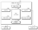
도 1을 참조하면, 일반적인 VMS 시스템은 마이크로 컨트롤러(Micro Controller Unit: MCU, 이하 'MCU'라 칭함)(10)와 VMS 컨트롤러(VMS Controller Unit: VCU, 'VCU'라 칭함)(12) 및 관제서버(2)를 포함한다.1, a general VMS system includes a microcontroller unit (MCU) 10, a VMS controller unit (VCU) 12, and a control unit And a
통상의 VMS 시스템은 MCU(10)와 VCU(12)가 분리된다. 이때, 분리는 물리적 및/또는 기능적 분리를 포함한다. 예를 들어, MCU(10)는 VMS 시스템의 다리 쪽의 함체(case)에 마련되고, VCU(12)는 영상 및 문자 등의 정보가 표출되는 VMS에 마련된다. 현재 VMS의 정보 표출 구조는, MCU(10)가 관제서버(2)로부터 신호를 수신하여 이를 VCU(12)에 전달하면 VCU(12)가 정보를 표출하는 구조로 되어 있다.In a typical VMS system, the MCU 10 and the
세부적으로, MCU(10)는 마이크로 프로세서(micro processing Unit)(100)와 MCU 통신부(102)를 포함한다. 마이크로 프로세서(100)는 마이크로 컨트롤러 기능을 수행하는 산업용 PC 이다. MCU 통신부(102)는 VCU(12)와 통신하기 위한 제1 통신부(102-1)와, 관제서버(2)와 통신하기 위한 제2 통신부(102-2)를 포함한다. 제1 통신부(102-1)와 제2 통신부(102-2)는 각각 VCU(12) 및 관제서버(2)와 TCP/IP 통신을 수행할 수 있다.In detail, the MCU 10 includes a
VCU(12)는 센트럴 프로세서(Central Processing Unit: CPU, 이하 'CPU'라 칭함)(120), VMS 표출부(122), VCU 통신부(124) 및 메모리(126)를 포함한다. CPU(120)는 VMS 컨트롤러 기능을 수행한다. VMS 표출부(122)는 VMS를 통해 영상과 문자 등으로 정보를 표출한다. VCU 통신부(124)는 MCU(10)와 통신하여 VMS에 정보 표출을 위한 신호를 MCU(10)로부터 수신한다.The VCU 12 includes a central processing unit (CPU) 120, a
도 1에 도시된 바와 같은 통상의 VMS 시스템 구조는 제어를 위한 MCU(10)와 VCU(12)가 분리된 구조이다. 이 경우, 프로세서, 메모리, 시스템 전원, 화재 경보를 위한 센서, 카메라 등이 2개로 분리되어야 한다. 나아가, 통상의 VMS 시스템은 고장진단 기능이 탑재되어 있지 않으므로 시스템 고장의 진단이 어려우면 현장에서 고장 진단 확인이 필요하다.A typical VMS system structure as shown in FIG. 1 is a structure in which an MCU 10 and a
일 실시 예에 따라, 도로 전광판(VMS) 시스템의 VCU와 MCU 통합 제어장치 및 이를 이용한 고장진단 방법을 제안한다.According to one embodiment, a VCU and MCU integrated control apparatus of a road sign board (VMS) system and a fault diagnosis method using the same are proposed.
일 실시 예에 따른 VMS 통합 제어장치는, VMS 컨트롤러 기능에 마이크로 컨트롤러 기능이 통합되어 VMS 시스템을 제어하면서 시스템의 상태정보로부터 시스템 고장을 통합 진단하는 통합 프로세서와, 시스템의 구동 전원을 인가받는 전원 입력부와, 통합 프로세서의 제어에 따라 VMS를 통해 정보를 표출하는 VMS 표출부와, 통합 프로세서의 연산을 위한 데이터가 저장되는 메모리와, 통합 프로세서의 고장 진단에 따라 시스템 상태정보를 포함한 고장 진단결과를 전송하는 통신부를 포함한다.A VMS integrated controller according to an exemplary embodiment includes an integrated processor that integrates a microcontroller function with a VMS controller function to integrally diagnose a system failure from state information of the system while controlling the VMS system, A VMS display unit for displaying information through the VMS under the control of the integrated processor, a memory for storing data for operation of the integrated processor, and a fault diagnosis result including the system status information according to the fault diagnosis of the integrated processor And a communication unit.
일 실시 예에 따른 통합 프로세서는, 시스템의 전원 상태를 확인하여 시스템 전원의 고장 여부를 점검하는 시스템 전원 고장 진단부와, 통합 프로세서의 사용량을 확인하여 시스템의 부하 상태를 점검하는 프로세서 고장 진단부와, 메모리 스캔을 통해 메모리 상태를 점검하는 메모리 고장 진단부와, LED 모듈의 상태를 확인하여 LED 모듈의 고장 여부를 점검하는 LED 모듈 고장 진단부를 포함한다.The integrated processor according to an embodiment includes a system power failure diagnosis unit for checking a power state of the system to check whether a system power source is faulty, a processor fault diagnosis unit for checking a usage state of the integrated processor to check a load state of the system, A memory fault diagnosis unit for checking memory status through a memory scan, and an LED module fault diagnosis unit for checking the status of the LED module to check whether the LED module is faulty.
시스템 전원 고장 진단부는, 시스템 전원의 전압 값을 측정하여 시스템 전원의 고장 여부를 판단하고 비정상인 경우 시스템 전원 전압 값을 제공할 수 있다.The system power failure diagnosis unit can determine the failure of the system power by measuring the voltage value of the system power supply and provide the system power voltage value in case of abnormality.
프로세서 고장 진단부는, 통합 프로세서의 시스템 점유율 및 상태를 확인하여 통합 프로세서의 고장 여부를 판단하고 비정상인 경우 통합 프로세서의 상태정보를 제공할 수 있다.The processor fault diagnosis unit can determine whether the integrated processor is faulty by checking the system occupancy and status of the integrated processor, and can provide the status information of the integrated processor in case of abnormality.
LED 모듈 고장 진단부는, LED 모듈의 전압 및 전류를 측정하고 측정전압 및 측정전류를 미리 설정된 기준전압 및 기준전류와 비교하여 LED 모듈의 고장 여부를 판단하고 비정상인 경우 LED 모듈의 측정전압 및 측정전류 값을 제공할 수 있다.The LED module fault diagnosis unit measures the voltage and current of the LED module and compares the measured voltage and the measured current with the preset reference voltage and reference current to determine whether the LED module is faulty or not. Value. ≪ / RTI >
통합 프로세서는, 고장진단에 따른 상태정보를 생성하여 제공하되, 상태정보는 고장진단 값, 고장진단 유형 및 상태 값으로 구성되며, 고장진단에 따른 상태정보를 암호화하여 제공할 수 있다.The integrated processor generates and provides state information according to the fault diagnosis, and the state information includes the fault diagnosis value, the fault diagnosis type, and the state value, and the state information according to the fault diagnosis can be encrypted and provided.
VMS 통합 제어장치는, VMS의 화재 발생 경보를 위해 VMS에 장착된 센서로부터 VMS 센싱정보를 획득하는 센싱정보 입력부를 더 포함하며, 통합 프로세서는 센서의 고장 여부를 점검하고 센서 고장 시 센서의 동작상태 정보를 제공하는 센서 고장 진단부를 더 포함할 수 있다.The VMS integrated control device further includes a sensing information input unit for acquiring VMS sensing information from a sensor mounted on the VMS for a fire alarm of the VMS. The integrated processor checks whether the sensor is faulty, And a sensor failure diagnosis unit for providing information.
통합 프로세서는, VMS를 감시하고 있는 카메라의 고장 여부를 점검하고 카메라 고장 시 카메라의 동작상태 정보를 제공하는 카메라 고장 진단부를 더 포함할 수 있다.The integrated processor may further include a camera malfunction diagnosis unit for checking malfunction of the camera monitoring the VMS and providing information on the operation state of the camera when the camera malfunctions.
통신부는, 고장 점검을 위한 모니터링 단말과 유선통신 방식 및 무선통신 방식 중 적어도 하나를 사용하여 통신할 수 있다.The communication unit can communicate with a monitoring terminal for fault checking using at least one of a wired communication method and a wireless communication method.
VMS 통합 제어장치는, 고장진단 프로그램과 연결되어 고장진단을 위한 시스템 상태정보를 전송하기 위한 입출력 인터페이스를 더 포함할 수 있다.The VMS integrated control device may further include an input / output interface connected to the fault diagnosis program and transmitting system status information for fault diagnosis.
일 실시 예에 따른 VMS 통합 제어장치는 VMS 컨트롤러 기능과 마이크로 컨트롤러 기능이 하나로 통합됨에 따라 그 구조가 단순화된다. 통상의 VMS 시스템은 MCU 및 VCU 2개의 제어장치로 분리되어 있어 프로세서, 메모리, 시스템 전원 등이 각각 2개씩 분리된 구조이지만, 일 실시 예에 따른 VMS 통합 제어장치는 하나의 제어장치로 통합됨에 따라 단일의 통합 프로세서, 단일의 전원 입력부 및 단일의 메모리로 구성되어 그 구조를 단순화할 수 있으며 원가가 절감된다.The VMS integrated controller according to the embodiment simplifies the structure by integrating the VMS controller function and the micro controller function into one. Since the conventional VMS system is divided into two MCUs and two VCU controllers, the processor, the memory, and the system power are separated into two, respectively. However, the VMS integrated controller according to one embodiment is integrated into one controller A single integrated processor, a single power input, and a single memory, simplifying the structure and reducing costs.
일 실시 예에 따른 VMS 통합 제어장치에는 VMS 시스템 고장진단 기능이 탑재되어 VMS 시스템의 상태정보로부터 시스템 고장을 진단할 수 있고, 특히 원격진단이 가능하여 A/S의 편의성이 증대된다. 나아가, VMS 통합 제어장치는 VMS 컨트롤러 기능에 마이크로 컨트롤러 기능이 통합되어 VMS 시스템 고장을 통합 진단할 수 있다. 예를 들어, 통상의 VMS 시스템 환경에서는 VMS 시스템을 중단하고, 현장에서 직접 고장의 원인을 찾기 위해 MCU와 VCU 각각에서 고장을 진단해야 하므로, 고장이 났을 때 MCU와 VCU 중 어느 부분에서 고장이 났는지를 하나하나 직접 확인해야 한다. 따라서, 진단을 위한 비용 및 시간이 발생하고, 이에 따른 불편함이 있다. 그러나 일 실시 예에 따른 VMS 통합 제어장치는 시스템 고장을 통합 진단하면 되므로, MCU와 VCU 각각에 대한 고장진단을 수행할 필요가 없게 된다.The VMS integrated controller according to an exemplary embodiment is equipped with a VMS system failure diagnosis function to diagnose a system failure from state information of the VMS system, and in particular, remote diagnosis can be performed, thereby increasing convenience of A / S. Furthermore, the VMS integrated control unit incorporates microcontroller functions into the VMS controller function, allowing integrated diagnosis of VMS system faults. For example, in a typical VMS system environment, the VMS system must be shut down and the MCU and VCU must be diagnosed to find the cause of the fault directly in the field. Therefore, when the MCU or VCU fails, Must be checked individually. Therefore, a cost and a time for diagnosis occur, which is inconvenient. However, since the VMS integrated controller according to the embodiment can diagnose system faults in an integrated manner, there is no need to perform a fault diagnosis for each of the MCU and the VCU.
또한, 현장에 직접 출동하지 않고 VMS 시스템 상태를 원격으로 모니터링할 수 있으며, 고장 수리 시에 VMS 시스템과의 통신을 통해 쉽고 정확하게 고장 확인 및 점검이 가능하다.In addition, VMS system status can be monitored remotely without dispatching directly to the site, and it can be easily and accurately checked and checked for faults through communication with the VMS system at the time of fault repair.
도 1은 일반적인 VMS 시스템의 구성을 도시한 도면,
도 2는 본 발명의 일 실시 예에 따른 VMS 시스템의 구성을 도시한 도면,
도 3은 본 발명의 일 실시 예에 따른 도 2의 통합 프로세서의 세부 구성을 도시한 도면,
도 4는 본 발명의 일 실시 예에 따른 시스템 전원 고장 진단 프로세스를 도시한 도면,
도 5는 본 발명의 일 실시 예에 따른 LED 모듈 고장 진단 프로세스를 도시한 도면,
도 6은 본 발명의 일 실시 예에 따른 프로세서 고장 진단 프로세스를 도시한 도면,
도 7은 본 발명의 일 실시 예에 따른 메모리 고장 진단 프로세스를 도시한 도면,
도 8은 본 발명의 일 실시 예에 따른 센서 고장 진단 프로세스를 도시한 도면,
도 9는 본 발명의 일 실시 예에 따른 카메라 고장 진단 프로세스를 도시한 도면,
도 10은 본 발명의 일 실시 예에 따른 고장관련 레지스터 맵을 도시한 도면,
도 11은 본 발명의 일 실시 예에 따른 VMS 시스템의 구성을 도시한 도면이다.Brief Description of the Drawings Fig. 1 is a diagram showing the configuration of a general VMS system,
2 is a diagram illustrating a configuration of a VMS system according to an embodiment of the present invention.
FIG. 3 illustrates a detailed configuration of the integrated processor of FIG. 2 according to one embodiment of the present invention; FIG.
FIG. 4 illustrates a process of diagnosing a system power failure according to an embodiment of the present invention; FIG.
FIG. 5 illustrates a process of diagnosing an LED module failure according to an embodiment of the present invention; FIG.
6 illustrates a process for diagnosing a processor failure according to an embodiment of the present invention;
Figure 7 illustrates a memory fault diagnosis process in accordance with one embodiment of the present invention;
FIG. 8 illustrates a sensor fault diagnosis process according to an embodiment of the present invention; FIG.
FIG. 9 illustrates a camera failure diagnosis process according to an embodiment of the present invention; FIG.
Figure 10 illustrates a fault-related register map in accordance with an embodiment of the present invention;
11 is a diagram illustrating a configuration of a VMS system according to an embodiment of the present invention.
본 발명의 이점 및 특징, 그리고 그것들을 달성하는 방법은 첨부되는 도면과 함께 상세하게 후술되어 있는 실시 예들을 참조하면 명확해질 것이다. 그러나 본 발명은 이하에서 개시되는 실시 예들에 한정되는 것이 아니라 서로 다른 다양한 형태로 구현될 수 있으며, 단지 본 실시 예들은 본 발명의 개시가 완전하도록 하고, 본 발명이 속하는 기술분야에서 통상의 지식을 가진 자에게 발명의 범주를 완전하게 알려주기 위해 제공되는 것이며, 본 발명은 청구항의 범주에 의해 정의될 뿐이다. 명세서 전체에 걸쳐 동일 참조 부호는 동일 구성 요소를 지칭한다.BRIEF DESCRIPTION OF THE DRAWINGS The advantages and features of the present invention and the manner of achieving them will become apparent with reference to the embodiments described in detail below with reference to the accompanying drawings. The present invention may, however, be embodied in many different forms and should not be construed as being limited to the embodiments set forth herein. Rather, these embodiments are provided so that this disclosure will be thorough and complete, and will fully convey the concept of the invention to those skilled in the art. Is provided to fully convey the scope of the invention to those skilled in the art, and the invention is only defined by the scope of the claims. Like reference numerals refer to like elements throughout the specification.
본 발명의 실시 예들을 설명함에 있어서 공지 기능 또는 구성에 대한 구체적인 설명이 본 발명의 요지를 불필요하게 흐릴 수 있다고 판단되는 경우에는 그 상세한 설명을 생략할 것이며, 후술되는 용어들은 본 발명의 실시 예에서의 기능을 고려하여 정의된 용어들로서 이는 사용자, 운용자의 의도 또는 관례 등에 따라 달라질 수 있다. 그러므로 그 정의는 본 명세서 전반에 걸친 내용을 토대로 내려져야 할 것이다.DETAILED DESCRIPTION OF THE PREFERRED EMBODIMENTS In the following description of the present invention, detailed description of known functions and configurations incorporated herein will be omitted when it may make the subject matter of the present invention rather unclear. , Which may vary depending on the intention or custom of the user, the operator, and the like. Therefore, the definition should be based on the contents throughout this specification.
첨부된 블록도의 각 블록과 흐름도의 각 단계의 조합들은 컴퓨터 프로그램인스트럭션들(실행 엔진)에 의해 수행될 수도 있으며, 이들 컴퓨터 프로그램 인스트럭션들은 범용 컴퓨터, 특수용 컴퓨터 또는 기타 프로그램 가능한 데이터 프로세싱 장비의 프로세서에 탑재될 수 있으므로, 컴퓨터 또는 기타 프로그램 가능한 데이터 프로세싱 장비의 프로세서를 통해 수행되는 그 인스트럭션들이 블록도의 각 블록 또는 흐름도의 각 단계에서 설명된 기능들을 수행하는 수단을 생성하게 된다.Each block of the accompanying block diagrams and combinations of steps of the flowcharts may be performed by computer program instructions (execution engines), which may be stored in a general-purpose computer, special purpose computer, or other processor of a programmable data processing apparatus The instructions that are executed through the processor of the computer or other programmable data processing equipment will generate means for performing the functions described in each block or flowchart of the block diagram.
이들 컴퓨터 프로그램 인스트럭션들은 특정 방식으로 기능을 구현하기 위해 컴퓨터 또는 기타 프로그램 가능한 데이터 프로세싱 장비를 지향할 수 있는 컴퓨터 이용가능 또는 컴퓨터 판독 가능 메모리에 저장되는 것도 가능하므로, 그 컴퓨터 이용가능 또는 컴퓨터 판독 가능 메모리에 저장된 인스트럭션들은 블록도의 각 블록 또는 흐름도의 각 단계에서 설명된 기능을 수행하는 인스트럭션 수단을 내포하는 제조 품목을 생산하는 것도 가능하다.These computer program instructions may also be stored in a computer usable or computer readable memory capable of directing a computer or other programmable data processing apparatus to implement the functionality in a particular manner so that the computer usable or computer readable memory It is also possible for the instructions stored in the block diagram to produce an article of manufacture containing instruction means for performing the functions described in each block or flowchart of the flowchart.
그리고 컴퓨터 프로그램 인스트럭션들은 컴퓨터 또는 기타 프로그램 가능한 데이터 프로세싱 장비 상에 탑재되는 것도 가능하므로, 컴퓨터 또는 기타 프로그램 가능한 데이터 프로세싱 장비 상에서 일련의 동작 단계들이 수행되어 컴퓨터로 실행되는 프로세스를 생성해서 컴퓨터 또는 기타 프로그램 가능한 데이터 프로세싱 장비를 수행하는 인스트럭션들은 블록도의 각 블록 및 흐름도의 각 단계에서 설명되는 기능들을 실행하기 위한 단계들을 제공하는 것도 가능하다.And computer program instructions may be loaded onto a computer or other programmable data processing equipment so that a series of operating steps may be performed on a computer or other programmable data processing equipment to create a computer- It is also possible that the instructions that perform the data processing equipment provide the steps for executing the functions described in each block of the block diagram and at each step of the flowchart.
또한, 각 블록 또는 각 단계는 특정된 논리적 기능들을 실행하기 위한 하나 이상의 실행 가능한 인스트럭션들을 포함하는 모듈, 세그먼트 또는 코드의 일부를 나타낼 수 있으며, 몇 가지 대체 실시 예들에서는 블록들 또는 단계들에서 언급된 기능들이 순서를 벗어나서 발생하는 것도 가능함을 주목해야 한다. 예컨대, 잇달아 도시되어 있는 두 개의 블록들 또는 단계들은 사실 실질적으로 동시에 수행되는 것도 가능하며, 또한 그 블록들 또는 단계들이 필요에 따라 해당하는 기능의 역순으로 수행되는 것도 가능하다.Also, each block or step may represent a portion of a module, segment, or code that includes one or more executable instructions for executing the specified logical functions, and in some alternative embodiments, It should be noted that functions may occur out of order. For example, two successive blocks or steps may actually be performed substantially concurrently, and it is also possible that the blocks or steps are performed in the reverse order of the function as needed.
이하, 첨부 도면을 참조하여 본 발명의 실시 예를 상세하게 설명한다. 그러나 다음에 예시하는 본 발명의 실시 예는 여러 가지 다른 형태로 변형될 수 있으며, 본 발명의 범위가 다음에 상술하는 실시 예에 한정되는 것은 아니다. 본 발명의 실시 예는 이 발명이 속하는 기술분야에서 통상의 지식을 가진 자에게 본 발명을 보다 완전하게 설명하기 위하여 제공된다.Hereinafter, embodiments of the present invention will be described in detail with reference to the accompanying drawings. However, the following embodiments of the present invention may be modified into various other forms, and the scope of the present invention is not limited to the embodiments described below. The embodiments of the present invention are provided to enable those skilled in the art to more fully understand the present invention.
도 2는 본 발명의 일 실시 예에 따른 VMS 시스템의 구성을 도시한 도면이다.2 is a diagram illustrating a configuration of a VMS system according to an embodiment of the present invention.
도 2를 참조하면, VMS 시스템은 VMS 통합 제어장치(20) 및 관제서버(2)를 포함한다. VMS 통합 제어장치(20)는 통합 프로세서(200), 전원 입력부(201), 메모리(202), VMS 표출부(203), 센싱정보 입력부(204), 통신부(205) 및 입출력 인터페이스(206)를 포함한다.Referring to FIG. 2, the VMS system includes a VMS
VMS 통합 제어장치(20)는 도 1의 VCU(12)에 MCU(10) 기능이 포함되어 있는 형태이다. 이를 위해, 통합 프로세서(200)는 VCU(12)의 VMS 컨트롤러 기능에 MCU(10)의 마이크로 컨트롤러 기능이 통합되어 VMS 시스템을 제어한다. VMS 통합 제어장치(20)는 도 1의 VCU(12) 위치에 구비될 수 있다. 도 1을 참조로 하여 전술한 통상의 VMS 시스템은 MCU(10) 및 VCU(12) 2개의 제어장치로 분리되어 있어 프로세서, 메모리, 시스템 전원 등이 각각 2개씩 분리된 구조이다. 그러나 일 실시 예에 따른 VMS 통합 제어장치(20)는 도 1의 VCU(12) 기능 및 MCU(10) 기능이 하나의 제어장치로 통합됨에 따라, 단일의 통합 프로세서(200), 단일의 전원 입력부(201) 및 단일의 메모리(202)로 구성되어 그 구조를 단순화할 수 있다.The VMS integrated
일 실시 예에 따른 VMS 통합 제어장치(20)에는 도 1을 참조로 하여 전술한 통상의 VMS 시스템에서는 없었던 고장진단 기능이 탑재된다. 이에 따라, VMS 시스템 고장을 진단할 수 있고, 특히 원격진단이 가능하다. 나아가, VMS 통합 제어장치(20)는 도 1의 VCU(12) 기능 및 MCU(10) 기능이 통합됨에 따라, 고장진단을 위해 도 1의 MCU(10)와 VCU(12)를 각각 점검할 필요가 없다. 통상의 VMS 시스템 환경에서는 VMS 시스템을 중단하고, 현장에서 직접 고장의 원인을 찾기 위해 MCU(10)와 VCU(12) 각각에서 고장을 진단해야 하므로, 고장이 났을 때 MCU(10)와 VCU(12) 중 어느 부분에서 고장이 났는지를 하나하나 직접 확인해야 한다. 따라서, 진단을 위한 비용 및 시간이 발생하고, 이에 따른 불편함이 있다. 그러나 일 실시 예에 따른 VMS 통합 제어장치(20)는 단일의 VMS 통합 제어장치(20)에 의해 시스템 고장을 통합 진단하면 되므로, 도 1의 MCU(10)와 VCU(12) 각각에 대한 고장진단을 수행할 필요가 없게 된다. 나아가, 현장에 직접 출동하지 않고 VMS 시스템 상태를 원격으로 모니터링할 수 있으며, 고장 수리 시에 VMS 시스템과의 통신을 통해 쉽고 정확하게 고장 확인 및 점검이 가능하다.The VMS integrated
일 실시 예에 따른 통합 프로세서(200)는 고장진단에 따른 상태정보를 생성하여 제공한다. 상태정보는 고장진단 값, 고장진단 유형 및 상태 값으로 구성되는데, 상태정보의 실시 예는 도 10을 참조로 하여 후술한다. 통합 프로세서(200)는 고장진단에 따른 상태정보를 암호화하여 제공할 수 있다. 암호화 방식은 CRC(cyclical redundancy check) 방식 등이 있으나, 이에 한정되는 것은 아니다. 암호화하면, 데이터를 송수신하는 과정에서의 오류를 최소화할 수 있다. 시스템 고장진단을 위한 통합 프로세서(200)의 세부 구성은 도 3을 참조로 하여 후술한다.The
전원 입력부(201)는 VMS 시스템의 구동 전원을 인가받는다. VMS 표출부(203)는 통합 프로세서의 제어에 따라 VMS를 통해 정보를 표출한다. 메모리(202)는 통합 프로세서(200)의 연산을 위한 데이터가 저장된다. 메모리(202)는 SDRAM, 플래시 메모리 등일 수 있다.The
통신부(205)는 VMS 정보 표출을 위한 신호를 수신하여 통합 프로세서(200)에 전달한다. VMS 정보 표출을 위한 신호는 관제서버(2)로부터 수신할 수 있다. 통신부(205)는 통합 프로세서(200)의 고장 진단에 따라 시스템 상태정보를 포함한 고장 진단결과를 관제서버(2)에 전송한다. 관제서버(2)에는 VMS 시스템을 모니터링하기 위한 모니터링 단말이 위치할 수 있다. 일 실시 예에 따른 통신부(205)는 고장 점검 모니터링을 위해 모니터링 단말과 유선통신 방식, 무선통신 방식 등을 사용하여 통신한다. 무선통신 방식은 관제서버(2)와 같이 모니터링 단말이 원격에 위치할 경우 원격 진단을 위해 사용될 수 있다. 유선통신 방식은 TCP/IP 통신, 시리얼 통신(RS-232, RS-422, RS-485), 광통신 등이 가능하다. 무선통신 방식은 블루투스(Bluetooth), 지그비(Zigbee), 와이파이(Wi-Fi), RoLa 등이 있다.The
일 실시 예에 따른 통신부(205)는 기가비트 이더넷 트랜시버일 수 있는데, 예를 들어 100BaseT 물리계층(PHY) 기능부일 수 있다. 100BaseT는 고속 이더넷(Fast Ethernet)과 같은 용어로, 컴퓨터들을 LAN에 연결 시키는 향상된 표준을 말한다. 물리계층(PHY) 기능부는 컴퓨터 네트워크의 최하위 계층 구조로서 데이터의 하드웨어 전송기술로 구성된다. 네트워크 어댑터, 모뎀, 허브가 이 계층이 실제 구현된 것이다. 10Mbps부터 10Gbps까지 다양한 종류가 있다.The
입출력 인터페이스(206)는 고장진단 프로그램(3)과 연결되어 고장진단을 위한 시스템 상태정보를 입출력한다. 고장진단 프로그램(3)은 모니터링 단말에 설치되어, 입출력 인터페이스(206)를 통해 VMS 통합 제어장치(20)에 연결 시, VMS 시스템을 모니터링하면서 고장진단을 수행할 수 있다.The input /
일 실시 예에 따른 입출력 인터페이스(206)는 유아트(Universal asynchronous receiver/transmitter: UART, 이하 UART라 칭함), 제이택(Joint Test Action Group: JTAG, 이하 JTAG라 칭함), 다용도 입출력 포트(General-purpose input/output: GPIO, 이하 GPIO라 칭함) 등일 수 있다. UART는 UART 시리얼 포트일 수 있다. JTAG는 JTAG 포트일 수 있다. UART는 병렬 데이터의 형태를 직렬 방식으로 전환하여 데이터를 전송하는 비동기 데이터 전송용 인터페이스이다. UART는 일반적으로 EIA RS-232, RS-422, RS-485와 같은 통신 표준과 함께 사용한다. JTAG은 디지털 회로에서 특정 노드의 디지털 입출력을 위해 직렬 통신 방식으로 출력 데이터를 전송하거나 입력 데이터를 수신하는 방식을 말한다. JTAG은 IEEE 1149.1에 표준으로 정해져 있다.The input /
도 3은 본 발명의 일 실시 예에 따른 도 2의 통합 프로세서의 세부 구성을 도시한 도면이다.3 is a detailed block diagram of the integrated processor of FIG. 2 according to an embodiment of the present invention.
도 2 및 도 3을 참조하면, 통합 프로세서(200)는 시스템 전원 고장 진단부(2000), 프로세서 고장 진단부(2001), 메모리 고장 진단부(2002) 및 LED 모듈 고장 진단부(2004)를 포함하며, 센서 고장 진단부(2006)와 카메라 고장 진단부(2008)를 더 포함할 수 있다.2 and 3, the
시스템 전원 고장 진단부(2000)는 VMS 시스템의 전원 상태를 확인하여 VMS 시스템 전원의 고장 여부를 점검한다. 일 실시 예에 따른 시스템 전원 고장 진단부(2000)는 VMS 시스템 전원의 전압 값을 측정하여 VMS 시스템 전원의 고장 여부를 판단한다. 비정상인 경우 VMS 시스템 전원 전압 값을 제공한다.The system power
프로세서 고장 진단부(2001)는 통합 프로세서(200)의 사용량을 점검하여 VMS 시스템의 부하 상태를 점검한다. 일 실시 예에 따른 프로세서 고장 진단부(2001)는 통합 프로세서(200)의 시스템 점유율 및 상태를 확인하여 통합 프로세서(200)의 고장 여부를 판단한다. 비정상인 경우 통합 프로세서(200)의 상태정보를 제공한다.The processor
메모리 고장 진단부(2002)는 메모리 스캔을 통해 메모리 상태를 점검한다.The memory
LED 모듈 고장 진단부(2004)는 LED 모듈의 상태를 확인하여 LED 모듈의 고장 여부를 점검한다. 일 실시 예에 따른 LED 모듈 고장 진단부(2004)는 LED 모듈의 전압 및 전류를 측정하고 측정전압 및 측정전류를 미리 설정된 기준전압 및 기준전류와 비교하여 LED 모듈의 고장 여부를 판단한다. 비정상인 경우 LED 모듈의 측정전압 및 측정전류 값을 제공한다.The LED module
센서 고장 진단부(2006)는 VMS의 화재 발생을 포함한 고장 진단을 위해 센서의 고장 여부를 점검하고, 센서 고장 시 센서의 동작상태 정보를 제공한다. 카메라 고장 진단부(2008)는 VMS를 감시하고 있는 카메라의 고장 여부를 점검하고 카메라 고장 시 카메라의 동작상태 정보를 제공한다.The sensor fault diagnosis unit (2006) checks the fault of the sensor for the fault diagnosis including the fire of the VMS, and provides the operation state information of the sensor when the sensor is faulty. The camera
도 4 내지 도 8은 본 발명의 일 실시 예에 따른 VMS 통합 제어장치를 통한 고장진단 방법을 설명하기 위한 프로세스를 도시한 도면이다.4 to 8 are views illustrating a process for explaining a failure diagnosis method using the VMS integrated control apparatus according to an embodiment of the present invention.
도 2 내지 도 8을 참조하면, VMS 통합 제어장치(20)의 통합 프로세서(200)는 VMS 시스템의 상태정보를 획득하여 VMS 시스템의 고장을 진단하고, VMS 시스템의 상태정보를 포함한 진단결과를 모니터링 단말에 전송한다. 모니터링 단말은 원격의 관제서버에 위치할 수 있고, 현장에서 입출력 인터페이스를 통해 연결될 수 있다. 모니터링 단말에는 고장진단 프로그램이 포함될 수 있다. 고장진단 프로그램은 시스템 모니터링 로그(Log)를 수집 및 분석하여 비정상 시에 이를 알리는 알람 메시지를 출력할 수 있다.Referring to FIGS. 2 to 8, the
이하, 후술되는 도면들을 참조로 하여, VMS 통합 제어장치를 통한 고장진단 프로세스에 대해 후술한다.The fault diagnosis process through the VMS integrated control apparatus will be described below with reference to the drawings described later.
세부적으로, 도 4는 본 발명의 일 실시 예에 따른 시스템 전원 고장 진단 프로세스를 도시한 도면이다.In detail, FIG. 4 illustrates a system power failure diagnostic process according to an embodiment of the present invention.
도 2 내지 도 4를 참조하면, 통합 프로세서(200)의 시스템 전원 고장 진단부(2000)는 VMS 시스템의 전원 상태를 확인하여 VMS 시스템 전원의 고장 여부를 점검한다. 이때, VMS 시스템 전원의 전압 값을 측정하여 VMS 시스템 전원의 고장 여부를 판단할 수 있다. 예를 들어, 시스템 전원이 5.5V이면, 출력전압 Vout = Vin × R2/R1+R2이므로, Vin = 5.0V, R1= 1.7Kohm, R2 = 2.2Kohm 이 되며, 시스템 전원 고장 진단부(2000)는 통합 프로세서(200) 내 ADC를 통해 출력전압 Vout을 모니터링 한다. 이때, 비정상일 때, 예를 들어 출력 전압 Vout과 미리 설정된 차이 이상이 발생하면, VMS 시스템 전원의 전압 값을 모니터링 단말에 전송한다. 모니터링 단말의 고장진단 프로그램은 시스템 모니터링 로그(Log)를 수집 및 분석하여 비정상 시에 이를 알리는 알람 메시지를 출력할 수 있다.2 to 4, the system power
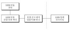
도 5는 본 발명의 일 실시 예에 따른 LED 모듈 고장 진단 프로세스를 도시한 도면이다.5 is a diagram illustrating an LED module failure diagnosis process according to an exemplary embodiment of the present invention.
도 2, 도 3 및 도 5를 참조하면, 통합 프로세서(200)의 LED 모듈 고장 진단부(2004)는 LED 모듈의 상태를 확인하여 LED 모듈의 고장 여부를 점검한다. 일 실시 예에 따른 LED 모듈 고장 진단부(2004)는 LED 모듈의 전압 및 전류를 측정하고 측정전압 및 측정전류를 미리 설정된 기준전압 및 기준전류와 비교하여 LED 모듈의 고장 여부를 판단한다. 비정상인 경우 LED 모듈의 측정전압 및 측정전류 값을 제공한다.2, 3, and 5, the LED module
LED 모듈의 전원은 5.5V를 사용하며 LED 모듈의 전압 및 전류를 확인하고, 정상이 아닌지 확인한다. 예를 들어, LED 모듈의 기준전압 5.0V를 기준으로 측정전압이 과전압(over voltage)인지 저전압(low voltage)인지를 확인하여, 과전압 또는 저전압인 경우 비정상으로 판단한다. 전류의 경우, 기준전류(최소전류: min 및 최대전류: max 사이)를 기준으로 측정전류가 과전류(over current)인지 저전류(low current) 인지를 확인하여 과전류 또는 저전류인 경우 비정상으로 판단한다. 비정상인 경우 LED 모듈의 측정전압 및 측정전류 값을 모니터링 단말에 제공한다. 모니터링 단말의 고장진단 프로그램은 시스템 모니터링 로그(Log)를 수집 및 분석하여 비정상 시에 이를 알리는 알람 메시지를 출력할 수 있다.Use 5.5 V for the power supply of the LED module, check the voltage and current of the LED module, and confirm that it is not normal. For example, it is determined whether the measured voltage is an over voltage or a low voltage based on a reference voltage of 5.0 V of the LED module, and it is judged to be abnormal when the voltage is over or under. In the case of the current, it is determined whether the measurement current is over current or low current based on the reference current (between the minimum current: min and the maximum current: max), and it is judged to be abnormal when the current is overcurrent or low current . In case of abnormality, the measurement voltage and the measured current value of the LED module are provided to the monitoring terminal. The fault diagnosis program of the monitoring terminal collects and analyzes the system monitoring log (Log) and can output an alarm message informing the abnormal state.
도 6은 본 발명의 일 실시 예에 따른 프로세서 고장 진단 프로세스를 도시한 도면이다.6 is a diagram illustrating a process for diagnosing a processor failure according to an embodiment of the present invention.
도 2, 도 3 및 도 6을 참조하면, 통합 프로세서(200)의 프로세서 고장 진단부(2001)는 통합 프로세서(200)의 사용량을 점검하여 VMS 시스템의 부하 상태를 점검한다. 일 실시 예에 따른 프로세서 고장 진단부(2001)는 통합 프로세서(200)의 시스템 점유율 및 상태를 확인하여 통합 프로세서(200)의 고장 여부를 판단한다. 비정상인 경우 통합 프로세서(200)의 상태정보를 모니터링 단말에 제공한다. 모니터링 단말의 고장진단 프로그램은 시스템 모니터링 로그(Log)를 수집 및 분석하여 비정상 시에 이를 알리는 알람 메시지를 출력할 수 있다.Referring to FIGS. 2, 3, and 6, the processor
도 7은 본 발명의 일 실시 예에 따른 메모리 고장 진단 프로세스를 도시한 도면이다.7 is a diagram illustrating a memory failure diagnosis process according to an embodiment of the present invention.
도 2, 도 3 및 도 7을 참조하면, 통합 프로세서(200)의 메모리 고장 진단부(2002)는 메모리 스캔을 통해 메모리 상태를 점검한다. 일 실시 예에 따른 메모리 고장 진단부(2002)는 메모리 불량 섹터(memory bad sector)를 스캔하여 메모리상태를 모니터링 하며, 메모리 불량 섹터의 어드레스가 통합 프로세서(200)의 시스템 점유율 및 통합 프로세서(200)의 상태를 모니터링 하여 메모리의 고장 여부를 판단한다. 비정상인 경우 메모리의 상태정보를 모니터링 단말에 제공한다. 모니터링 단말의 고장진단 프로그램은 시스템 모니터링 로그(Log)를 수집 및 분석하여 비정상 시에 이를 알리는 알람 메시지를 출력할 수 있다Referring to FIGS. 2, 3 and 7, the memory
도 8은 본 발명의 일 실시 예에 따른 센서 고장 진단 프로세스를 도시한 도면이다.8 is a diagram illustrating a sensor failure diagnosis process according to an embodiment of the present invention.
도 2, 도 3 및 도 8을 참조하면, 통합 프로세서(200)의 센서 고장 진단부(2006)는 VMS의 화재 발생을 포함한 고장 진단을 위해 센서의 고장 여부를 점검하고, 센서 고장 시 센서의 동작상태 정보를 모니터링 단말에 제공한다. 센서의 예는 도 11을 참조로 하여 후술한다.2, 3, and 8, the sensor
도 9는 본 발명의 일 실시 예에 따른 카메라 고장 진단 프로세스를 도시한 도면이다.9 is a diagram illustrating a camera failure diagnosis process according to an exemplary embodiment of the present invention.
도 2, 도 3 및 도 9를 참조하면, 통합 프로세서(200)의 카메라 고장 진단부(2008)는 VMS를 감시하고 있는 카메라의 고장 여부를 점검하고 카메라 고장 시 카메라의 동작상태 정보를 제공한다.Referring to FIGS. 2, 3 and 9, the camera
도 10은 본 발명의 일 실시 예에 따른 고장관련 레지스터 맵을 도시한 도면이다.10 is a diagram showing a fault-related register map according to an embodiment of the present invention.
도 10을 참조하면, 고장관련 상태 레지스터는 고장진단 값, 고장진단 유형 및 상태 값으로 구성된다. 예를 들어, 전원 고장의 경우, 고장진단 값은 0x01이고, 고장진단 유형은 0x11이며, 상태 값은 0x11~0xFF이다.Referring to Fig. 10, the fault related status register is composed of a fault diagnosis value, a fault diagnosis type, and a status value. For example, in case of power failure, the fault diagnosis value is 0x01, the fault diagnosis type is 0x11, and the state values are 0x11 to 0xFF.
도 11은 본 발명의 일 실시 예에 따른 VMS 시스템의 구성을 도시한 도면이다.11 is a diagram illustrating a configuration of a VMS system according to an embodiment of the present invention.
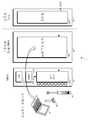
도 11을 참조하면, VMS 시스템은 VMS 통합 제어장치(20), 전원 공급부(22), VMS(24), 화재 경보기(26), 카메라(28) 및 모니터링 단말(4)을 포함한다. 모니터링 단말(4)은 도 1의 관제서버(2) 측에 위치할 수 있다.Referring to FIG. 11, the VMS system includes a VMS
VMS(24)는 N×M(N, M은 양의 정수) 개의 LED 모듈(240)을 포함한다. 각 LED 모듈(240)은 다수 개의 LED로 구성되어 각 LED의 발광 여부 및 세기에 따라 다양한 색상을 구현할 수 있다. 예를 들어, LED 모듈(240)의 면 상에 다수의 LED가 일정한 배열로 위치한다. VMS(24)는 도로 이용자에게 교통량, 교통사고, 정체구간, 기상상황 및 공사로 인한 통제 등에 대한 실시간 정보를 제공함으로써, 교통 흐름의 효율화와 통행의 안전성을 향상시키기 위한 장비를 말한다.The
VMS 통합 제어장치(20)는 VMS(24)를 제어한다. VMS 통합 제어장치(20)는 예를 들어, 컴퓨터일 수 있고, 소프트웨어 프로그램을 통해 제어가 이루어질 수 있다. 일 실시 예에 따른 VMS 통합 제어장치(20)는 VMS(24)의 화재발생을 예측하고 화재발생 시 경보신호를 생성 및 전송하며, 화재로부터 VMS(24)를 보호한다. VMS(24)의 화재는 사용자(예를 들어 운전자) 및 관리자에게 안전상의 가장 중요한 관리대상 중 하나이다. 본 발명은 센서(244)와 화재 경보기(26)를 VMS 시스템(1)에 추가하고, 모니터링 단말(4)로 화재 경보를 알림으로써, 화재로부터 VMS(24)를 보호할 수 있다.The VMS integrated
VMS(24)에는 환경정보를 센싱하기 위한 적어도 하나의 센서(244)가 포함된다. 환경정보는 온도, 습도, 연기 등일 수 있고, 센서는 온도를 감지하는 온도 센서, 습도를 감지하는 습도 센서, 연기를 감지하는 연기 센서 등일 수 있다. 센서(244)는 VMS(24)에 내장될 수 있고, 외장된 형태일 수도 있다. 환경정보 센싱은 실시간으로 이루어질 수 있고, 미리 설정된 주기 간격으로 이루어질 수 있으며, 화재관리단계에 따라 간격을 차별화할 수도 있다.The
VMS 통합 제어장치(20)는 센서(244)를 통해 센싱된 환경정보를 개별적 또는 조합적으로 분석하여 VMS(24)의 화재 이상징후 및 화재발생 여부를 판단한다. 이때, 화재발생단계(예를 들어, 임계치 온도를 초과하는 경우) 상태이면 환경정보 및 경보신호를 모니터링 단말(4)에 전송한 후, VMS(24)로의 전원 공급을 차단하여 자가진압할 수 있다. VMS 통합 제어장치(20)는 VMS(24)의 센싱정보를 모니터링 단말(4)에 전송하며, 환경정보 분석에 따른 화재 이상징후 및 화재발생 판단결과를 모니터링 단말(4)에 추가로 전송할 수 있다. VMS 통합 제어장치(20)는 모니터링 단말(4)로부터 제어명령을 입력받아 제어명령에 따라 VMS(24)를 제어할 수 있다.The VMS integrated
모니터링 단말(4)은 VMS 통합 제어장치(20)와 연결되어, VMS(24)의 상태를 모니터링 한다. 이 경우, 모니터링 단말(4)은 VMS 시스템의 고장 여부를 실시간으로 모니터링할 수 있다. 다른 예로, 모니터링 단말(4)은 VMS 통합 제어장치(20)를 통한 구분된 화재관리단계에 맞는 센싱정보를 수신할 수 있다. 예를 들어, VMS 통합 제어장치(20)가 화재발생단계 이전에 나타나는 이상 징후를 온도와 습도 감지 등을 통해 감지하면, 주의단계로 판단하고, 센싱정보를 모니터링 단말(4)에 통보한다. 모니터링 단말(4)은 다수 개의 VMS 통합 제어장치(20)와 접속이 가능하며, 실시간 모니터링이 가능하고, 그래프 및 엑셀(EXCEL) 형태의 자료로 편집하여 데이터를 화면에 출력하거나 저장할 수 있다. 모니터링 단말(4)은 VMS(24)에 설치된 카메라(28)를 이용하여 VMS(24)를 촬영하여 VMS(24)의 화재 이상징후 또는 화재발생 상태를 포함한 고장 여부를 모니터링할 수 있다.The monitoring terminal 4 is connected to the VMS
전원 공급부(22)는 시스템 구동 전원을 제공한다. 전원 공급부(22)는 배전 및 배전을 제어하는 배전반을 포함할 수 있다. 화재 경보기(26)는 VMS 통합 제어장치(20)에서 생성된 제어신호를, 화재관리단계에 따라 시각적으로 구별되는 시각정보로 변환하여 표출한다. 나아가, 화재발생단계에서 부저(buzzer)를 통해 경고음을 발생시킬 수 있다. 모니터링 단말(4)은 원거리에 위치하고, 화재 경보기(26)는 근거리에 위치할 수 있다. 예를 들어, VMS 통합 제어장치(20)는 원격지의 모니터링 단말(4)과는 TCP/IP 통신 방식으로 통신하고, 화재 경보기(26)와는 시리얼 통신(RS-232, RS-422, RS-485)이나 블루투스, 지그비와 같은 근거리 무선통신 방식으로 통신할 수 있다.The
이제까지 본 발명에 대하여 그 실시 예들을 중심으로 살펴보았다. 본 발명이 속하는 기술분야에서 통상의 지식을 가진 자는 본 발명이 본 발명의 본질적인 특성에서 벗어나지 않는 범위에서 변형된 형태로 구현될 수 있음을 이해할 수 있을 것이다. 그러므로 개시된 실시 예들은 한정적인 관점이 아니라 설명적인 관점에서 고려되어야 한다. 본 발명의 범위는 전술한 설명이 아니라 특허청구범위에 나타나 있으며, 그와 동등한 범위 내에 있는 모든 차이점은 본 발명에 포함된 것으로 해석되어야 할 것이다.The embodiments of the present invention have been described above. It will be understood by those skilled in the art that various changes in form and details may be made therein without departing from the spirit and scope of the invention as defined by the appended claims. Therefore, the disclosed embodiments should be considered in an illustrative rather than a restrictive sense. The scope of the present invention is defined by the appended claims rather than by the foregoing description, and all differences within the scope of equivalents thereof should be construed as being included in the present invention.
Claims (10)
Translated fromKorean시스템의 구동 전원을 인가받는 전원 입력부;
통합 프로세서의 제어에 따라 VMS를 통해 정보를 표출하는 VMS 표출부;
통합 프로세서의 연산을 위한 데이터가 저장되는 메모리; 및
통합 프로세서의 고장 진단에 따라 시스템 상태정보를 포함한 고장 진단결과를 전송하는 통신부; 를 포함하며,
상기 통합 프로세서는
시스템의 전원 상태를 확인하여 시스템 전원의 고장 여부를 점검하는 시스템 전원 고장 진단부;
통합 프로세서의 사용량을 확인하여 시스템의 부하 상태를 점검하는 프로세서 고장 진단부;
메모리 스캔을 통해 메모리 상태를 점검하는 메모리 고장 진단부; 및
LED 모듈의 상태를 확인하여 LED 모듈의 고장 여부를 점검하는 LED 모듈 고장 진단부;
를 포함하는 것을 특징으로 하는 VMS 통합 제어장치.Integrated processor that integrates micro controller function with VMS (Variable Message Sign) (VMS) controller to integrate diagnosis of system failure from system status information while controlling VMS system;
A power input unit receiving driving power of the system;
A VMS display unit for displaying information through the VMS under the control of the integrated processor;
A memory for storing data for operation of the integrated processor; And
A communication unit for transmitting a fault diagnosis result including system state information according to a fault diagnosis of the integrated processor; / RTI >
The integrated processor
A system power failure diagnosis unit for checking the power state of the system to check whether the power of the system is faulty;
A processor fault diagnosis unit for checking a usage state of the integrated processor to check a load state of the system;
A memory fault diagnosis unit for checking a memory state through a memory scan; And
An LED module fault diagnosis unit for checking the status of the LED module to check whether the LED module is faulty;
And the VMS integrated control device.
시스템 전원의 전압 값을 측정하여 시스템 전원의 고장 여부를 판단하고 비정상인 경우 시스템 전원 전압 값을 제공하는 것을 특징으로 하는 VMS 통합 제어장치.The system according to claim 2, wherein the system power failure diagnosis unit
Wherein the voltage value of the system power supply is measured to determine whether the system power supply is faulty or not, and when the voltage is abnormal, the system power supply voltage value is provided.
통합 프로세서의 시스템 점유율 및 상태를 확인하여 통합 프로세서의 고장 여부를 판단하고 비정상인 경우 통합 프로세서의 상태정보를 제공하는 것을 특징으로 하는 VMS 통합 제어장치.The system according to claim 2, wherein the processor failure diagnosis unit
Wherein the status of the integrated processor is checked by checking the system occupancy and status of the integrated processor, and if the integrated processor is abnormal, status information of the integrated processor is provided.
LED 모듈의 전압 및 전류를 측정하고 측정전압 및 측정전류를 미리 설정된 기준전압 및 기준전류와 비교하여 LED 모듈의 고장 여부를 판단하고 비정상인 경우 LED 모듈의 측정전압 및 측정전류 값을 제공하는 것을 특징으로 하는 VMS 통합 제어장치.The apparatus of claim 2, wherein the LED module failure diagnosis unit
It measures the voltage and current of the LED module, compares the measured voltage and the measured current with the preset reference voltage and reference current to determine whether the LED module is faulty or not, and provides the measured voltage and the measured current value of the LED module when it is abnormal VMS integrated control device.
고장진단에 따른 상태정보를 생성하여 제공하되, 상태정보는 고장진단 값, 고장진단 유형 및 상태 값으로 구성되며, 고장진단에 따른 상태정보를 암호화하여 제공하는 것을 특징으로 하는 VMS 통합 제어장치.3. The system of claim 2,
Wherein the state information comprises at least one of a failure diagnosis value, a failure diagnosis type, and a status value, wherein the status information is provided by encrypting the status information according to the failure diagnosis.
VMS의 화재 발생 경보를 위해 VMS에 장착된 센서로부터 VMS 센싱정보를 획득하는 센싱정보 입력부; 를 더 포함하며,
상기 통합 프로세서는
센서의 고장 여부를 점검하고 센서 고장 시 센서의 동작상태 정보를 제공하는 센서 고장 진단부; 를 더 포함하는 VMS 통합 제어장치.3. The system of claim 2, wherein the VMS integrated control device
A sensing information input unit for obtaining VMS sensing information from a sensor mounted on the VMS for a fire alarm of the VMS; Further comprising:
The integrated processor
A sensor fault diagnosis unit for checking the fault of the sensor and providing information on the operation state of the sensor in the event of a sensor failure; Further comprising a VMS integrated control device.
VMS를 감시하고 있는 카메라의 고장 여부를 점검하고 카메라 고장 시 카메라의 동작상태 정보를 제공하는 카메라 고장 진단부;
를 더 포함하는 VMS 통합 제어장치.3. The system of claim 2,
A camera fault diagnosis unit for checking whether a camera monitoring the VMS is faulty and providing information on the operation state of the camera when the camera is broken;
Further comprising a VMS integrated control device.
고장 점검을 위한 모니터링 단말과 유선통신 방식 및 무선통신 방식 중 적어도 하나를 사용하여 통신하는 것을 특징으로 하는 VMS 통합 제어장치.The communication device according to claim 2,
Wherein the communication is performed using at least one of a monitoring terminal for fault checking, a wired communication method, and a wireless communication method.
고장진단 프로그램과 연결되어 고장진단을 위한 시스템 상태정보를 전송하기 위한 입출력 인터페이스;
를 더 포함하는 것을 특징으로 하는 VMS 통합 제어장치.3. The system of claim 2, wherein the VMS integrated control device
An input / output interface connected to the fault diagnosis program for transmitting system status information for fault diagnosis;
The VMS integrated control apparatus further comprising:
Priority Applications (1)
| Application Number | Priority Date | Filing Date | Title |
|---|---|---|---|
| KR1020180048946AKR101949305B1 (en) | 2018-04-27 | 2018-04-27 | VMS controller with integrated VCU and MCU of VMS system and method for inspecting error using the same |
Applications Claiming Priority (1)
| Application Number | Priority Date | Filing Date | Title |
|---|---|---|---|
| KR1020180048946AKR101949305B1 (en) | 2018-04-27 | 2018-04-27 | VMS controller with integrated VCU and MCU of VMS system and method for inspecting error using the same |
Publications (1)
| Publication Number | Publication Date |
|---|---|
| KR101949305B1true KR101949305B1 (en) | 2019-02-19 |
Family
ID=65528630
Family Applications (1)
| Application Number | Title | Priority Date | Filing Date |
|---|---|---|---|
| KR1020180048946AActiveKR101949305B1 (en) | 2018-04-27 | 2018-04-27 | VMS controller with integrated VCU and MCU of VMS system and method for inspecting error using the same |
Country Status (1)
| Country | Link |
|---|---|
| KR (1) | KR101949305B1 (en) |
Cited By (14)
| Publication number | Priority date | Publication date | Assignee | Title |
|---|---|---|---|---|
| KR102002395B1 (en)* | 2019-05-08 | 2019-10-21 | 주식회사 맥서브 | CCTV and Lane Control System for Checking Operation Status Installed in Road and Tunnel |
| KR102064892B1 (en)* | 2019-08-30 | 2020-01-13 | 현대아이티에스전자(주) | Smart electronic display board with self-inspection and IoT convergence operational function |
| KR102217889B1 (en)* | 2020-05-26 | 2021-02-19 | 박영기 | LED Digital Signage Defect Detection System based on the detection of the cumulative current amount singular value |
| KR20220005770A (en)* | 2020-07-07 | 2022-01-14 | 한국전력공사 | System and Method for monitoring Remote Terminal Unit |
| KR102398761B1 (en)* | 2020-12-11 | 2022-05-17 | (주)티에이치엔 | Method and apparatus of securing message in network for vehicle |
| KR102398763B1 (en)* | 2020-12-11 | 2022-05-17 | (주)티에이치엔 | Method and apparatus of securing message in network for vehicle |
| KR102398762B1 (en)* | 2020-12-11 | 2022-05-17 | (주)티에이치엔 | Method and apparatus of securing message in network for vehicle according to condition of vehicle |
| KR102398764B1 (en)* | 2020-12-11 | 2022-05-17 | (주)티에이치엔 | Method and apparatus of securing message in network for vehicle |
| KR102537330B1 (en)* | 2023-02-03 | 2023-05-30 | 주식회사 비알인포텍 | VMS display control device with blackout compensation function and display control method thereof |
| KR20230089895A (en)* | 2021-12-14 | 2023-06-21 | 주식회사 케이시스 | Monitoring system of led display device based on big data using control signal |
| KR20230089894A (en)* | 2021-12-14 | 2023-06-21 | 주식회사 케이시스 | Monitoring system of led display device based on big data using test signal |
| KR102607261B1 (en)* | 2023-02-10 | 2023-11-29 | (주)에스엔테크 | Integrated guide display board |
| KR200498423Y1 (en)* | 2024-01-15 | 2024-10-14 | 김창 | Visual Control Unit having Energy saving function of Variable Speed Limit |
| KR102832068B1 (en)* | 2025-03-13 | 2025-07-09 | 오상록 | Hardware-based Remote Power Control and Recovery System for Electronic Display Board |
Citations (10)
| Publication number | Priority date | Publication date | Assignee | Title |
|---|---|---|---|---|
| KR19990083648A (en)* | 1998-07-21 | 1999-12-06 | 최병석 | Fault detection circuit of all-optical display device and display state detection method using same |
| KR20010045148A (en)* | 1999-11-03 | 2001-06-05 | 김종환 | An expression module with error checking ability for electric light board |
| KR200301822Y1 (en)* | 2002-09-30 | 2003-01-24 | 삼익전자공업 주식회사 | Electric bulletin board system for sensing display error |
| KR20050116457A (en)* | 2004-06-07 | 2005-12-13 | 김태연 | Apparatus and method for remote controling vms |
| KR20110003750A (en)* | 2009-07-06 | 2011-01-13 | 주식회사 아이딘컴 | LED display system with real-time remote monitoring |
| KR20120108836A (en)* | 2011-03-25 | 2012-10-05 | (주)주영통신기술 | Control system for sign device of road defensive driving |
| KR20140031713A (en)* | 2012-09-05 | 2014-03-13 | (주)유비쿼터스통신 | Electronic scoreboard monitoring system for controlling led electronic scoreboard with remote |
| KR101477013B1 (en)* | 2014-06-11 | 2015-01-07 | 서울디스플레이 주식회사 | Error recovery system and its method for electric light panel system |
| KR20160024294A (en)* | 2014-08-25 | 2016-03-04 | 한국전자공업협동조합 | Real time state management system for led electric light panel |
| KR101764009B1 (en)* | 2015-08-25 | 2017-08-02 | 한국공항공사 | Apparatus and method for monitoring electrical failure |
- 2018
- 2018-04-27KRKR1020180048946Apatent/KR101949305B1/enactiveActive
Patent Citations (10)
| Publication number | Priority date | Publication date | Assignee | Title |
|---|---|---|---|---|
| KR19990083648A (en)* | 1998-07-21 | 1999-12-06 | 최병석 | Fault detection circuit of all-optical display device and display state detection method using same |
| KR20010045148A (en)* | 1999-11-03 | 2001-06-05 | 김종환 | An expression module with error checking ability for electric light board |
| KR200301822Y1 (en)* | 2002-09-30 | 2003-01-24 | 삼익전자공업 주식회사 | Electric bulletin board system for sensing display error |
| KR20050116457A (en)* | 2004-06-07 | 2005-12-13 | 김태연 | Apparatus and method for remote controling vms |
| KR20110003750A (en)* | 2009-07-06 | 2011-01-13 | 주식회사 아이딘컴 | LED display system with real-time remote monitoring |
| KR20120108836A (en)* | 2011-03-25 | 2012-10-05 | (주)주영통신기술 | Control system for sign device of road defensive driving |
| KR20140031713A (en)* | 2012-09-05 | 2014-03-13 | (주)유비쿼터스통신 | Electronic scoreboard monitoring system for controlling led electronic scoreboard with remote |
| KR101477013B1 (en)* | 2014-06-11 | 2015-01-07 | 서울디스플레이 주식회사 | Error recovery system and its method for electric light panel system |
| KR20160024294A (en)* | 2014-08-25 | 2016-03-04 | 한국전자공업협동조합 | Real time state management system for led electric light panel |
| KR101764009B1 (en)* | 2015-08-25 | 2017-08-02 | 한국공항공사 | Apparatus and method for monitoring electrical failure |
Cited By (17)
| Publication number | Priority date | Publication date | Assignee | Title |
|---|---|---|---|---|
| KR102002395B1 (en)* | 2019-05-08 | 2019-10-21 | 주식회사 맥서브 | CCTV and Lane Control System for Checking Operation Status Installed in Road and Tunnel |
| KR102064892B1 (en)* | 2019-08-30 | 2020-01-13 | 현대아이티에스전자(주) | Smart electronic display board with self-inspection and IoT convergence operational function |
| KR102217889B1 (en)* | 2020-05-26 | 2021-02-19 | 박영기 | LED Digital Signage Defect Detection System based on the detection of the cumulative current amount singular value |
| KR20220005770A (en)* | 2020-07-07 | 2022-01-14 | 한국전력공사 | System and Method for monitoring Remote Terminal Unit |
| KR102548271B1 (en)* | 2020-07-07 | 2023-06-28 | 한국전력공사 | System and Method for monitoring Remote Terminal Unit |
| KR102398762B1 (en)* | 2020-12-11 | 2022-05-17 | (주)티에이치엔 | Method and apparatus of securing message in network for vehicle according to condition of vehicle |
| KR102398764B1 (en)* | 2020-12-11 | 2022-05-17 | (주)티에이치엔 | Method and apparatus of securing message in network for vehicle |
| KR102398763B1 (en)* | 2020-12-11 | 2022-05-17 | (주)티에이치엔 | Method and apparatus of securing message in network for vehicle |
| KR102398761B1 (en)* | 2020-12-11 | 2022-05-17 | (주)티에이치엔 | Method and apparatus of securing message in network for vehicle |
| KR102706333B1 (en) | 2021-12-14 | 2024-09-12 | 주식회사 케이시스 | Monitoring system of led display device based on big data using test signal |
| KR20230089895A (en)* | 2021-12-14 | 2023-06-21 | 주식회사 케이시스 | Monitoring system of led display device based on big data using control signal |
| KR20230089894A (en)* | 2021-12-14 | 2023-06-21 | 주식회사 케이시스 | Monitoring system of led display device based on big data using test signal |
| KR102706334B1 (en) | 2021-12-14 | 2024-09-12 | 주식회사 케이시스 | Monitoring system of led display device based on big data using control signal |
| KR102537330B1 (en)* | 2023-02-03 | 2023-05-30 | 주식회사 비알인포텍 | VMS display control device with blackout compensation function and display control method thereof |
| KR102607261B1 (en)* | 2023-02-10 | 2023-11-29 | (주)에스엔테크 | Integrated guide display board |
| KR200498423Y1 (en)* | 2024-01-15 | 2024-10-14 | 김창 | Visual Control Unit having Energy saving function of Variable Speed Limit |
| KR102832068B1 (en)* | 2025-03-13 | 2025-07-09 | 오상록 | Hardware-based Remote Power Control and Recovery System for Electronic Display Board |
Similar Documents
| Publication | Publication Date | Title |
|---|---|---|
| KR101949305B1 (en) | VMS controller with integrated VCU and MCU of VMS system and method for inspecting error using the same | |
| KR101895849B1 (en) | System for self-controlling and alarming fire of LED signboard based on calibration, transmission and sensing | |
| JP5886714B2 (en) | Portable equipment maintenance support device | |
| ES2392035T3 (en) | Communication error monitoring system of an Ethernet-based power device and its procedure | |
| US9952565B2 (en) | Networked, channelized power distribution, monitor and control for security and life safety applications | |
| US8793366B2 (en) | Method and arrangement for diagnosing networks including field bus systems | |
| KR102355242B1 (en) | Apparatus and method for diagnosing trouble of led module | |
| KR20180138354A (en) | System for detection of photovoltaic module using the unmanned aerial vehicle | |
| CN113282026B (en) | Mining information acquisition and fault diagnosis device and method | |
| US20200184801A1 (en) | Fire notification facility | |
| KR20200059388A (en) | Electricity Information Management System | |
| JP2023055960A (en) | Disaster prevention system and fire detector | |
| TWI583258B (en) | Fault detection apparatus and fault detection method | |
| KR20210059828A (en) | Apparatus of integrated interconnection and equipment management system having the same | |
| KR102706334B1 (en) | Monitoring system of led display device based on big data using control signal | |
| CN110806537A (en) | Method and system for monitoring state of air switch | |
| KR102545137B1 (en) | Control board for escalator and remote integrated control system including the same | |
| CN104503037A (en) | Optical transceiver module | |
| JP6622538B2 (en) | Disaster prevention monitoring system | |
| CN213461793U (en) | Light sense gateway and remote monitering system | |
| CN109450491B (en) | Cable modem system capable of monitoring temperature and implementation method thereof | |
| KR100760404B1 (en) | Pre-diagnosis system for electronic devices and pre-diagnosis method using the same | |
| KR101409486B1 (en) | Condition monitoring system having virtual sencor and condition monitoring method | |
| JP7755566B2 (en) | Disaster prevention monitoring system | |
| TW201730831A (en) | Debugging system, debugging method, and power management system |
Legal Events
| Date | Code | Title | Description |
|---|---|---|---|
| PA0109 | Patent application | Patent event code:PA01091R01D Comment text:Patent Application Patent event date:20180427 | |
| PA0201 | Request for examination | ||
| PA0302 | Request for accelerated examination | Patent event date:20180427 Patent event code:PA03022R01D Comment text:Request for Accelerated Examination | |
| PE0902 | Notice of grounds for rejection | Comment text:Notification of reason for refusal Patent event date:20180911 Patent event code:PE09021S01D | |
| E701 | Decision to grant or registration of patent right | ||
| PE0701 | Decision of registration | Patent event code:PE07011S01D Comment text:Decision to Grant Registration Patent event date:20190130 | |
| GRNT | Written decision to grant | ||
| PR0701 | Registration of establishment | Comment text:Registration of Establishment Patent event date:20190212 Patent event code:PR07011E01D | |
| PR1002 | Payment of registration fee | Payment date:20190212 End annual number:3 Start annual number:1 | |
| PG1601 | Publication of registration | ||
| PR1001 | Payment of annual fee | Payment date:20220210 Start annual number:4 End annual number:4 | |
| PR1001 | Payment of annual fee | Payment date:20230130 Start annual number:5 End annual number:5 | |
| PR1001 | Payment of annual fee | Payment date:20240311 Start annual number:6 End annual number:6 | |
| PR1001 | Payment of annual fee | Payment date:20250205 Start annual number:7 End annual number:7 |