KR101947519B1 - Showerhead having multi-layer and method for sealing the same - Google Patents
Showerhead having multi-layer and method for sealing the sameDownload PDFInfo
- Publication number
- KR101947519B1 KR101947519B1KR1020157018817AKR20157018817AKR101947519B1KR 101947519 B1KR101947519 B1KR 101947519B1KR 1020157018817 AKR1020157018817 AKR 1020157018817AKR 20157018817 AKR20157018817 AKR 20157018817AKR 101947519 B1KR101947519 B1KR 101947519B1
- Authority
- KR
- South Korea
- Prior art keywords
- gas
- guide pipe
- gas guide
- space
- plate
- Prior art date
- Legal status (The legal status is an assumption and is not a legal conclusion. Google has not performed a legal analysis and makes no representation as to the accuracy of the status listed.)
- Active
Links
- 238000000034methodMethods0.000titleclaimsdescription19
- 238000007789sealingMethods0.000titledescription7
- 239000000945fillerSubstances0.000claimsabstractdescription31
- 238000000926separation methodMethods0.000claimsabstractdescription22
- 238000005192partitionMethods0.000claimsabstractdescription18
- 239000007789gasSubstances0.000claimsdescription117
- 238000002347injectionMethods0.000claimsdescription18
- 239000007924injectionSubstances0.000claimsdescription18
- 238000005219brazingMethods0.000claimsdescription17
- PXHVJJICTQNCMI-UHFFFAOYSA-NNickelChemical compound[Ni]PXHVJJICTQNCMI-UHFFFAOYSA-N0.000description10
- 239000007788liquidSubstances0.000description5
- 229910052759nickelInorganic materials0.000description5
- ZOXJGFHDIHLPTG-UHFFFAOYSA-NBoronChemical compound[B]ZOXJGFHDIHLPTG-UHFFFAOYSA-N0.000description4
- 229910045601alloyInorganic materials0.000description4
- 239000000956alloySubstances0.000description4
- 229910052796boronInorganic materials0.000description4
- 239000011230binding agentSubstances0.000description3
- 238000005507sprayingMethods0.000description3
- 239000000758substrateSubstances0.000description3
- 238000004519manufacturing processMethods0.000description2
- 238000002844meltingMethods0.000description2
- 230000008018meltingEffects0.000description2
- 238000002156mixingMethods0.000description2
- 238000001039wet etchingMethods0.000description2
- 229910000990Ni alloyInorganic materials0.000description1
- 238000005260corrosionMethods0.000description1
- 230000007797corrosionEffects0.000description1
- 238000009792diffusion processMethods0.000description1
- 238000010438heat treatmentMethods0.000description1
- 238000002955isolationMethods0.000description1
- 238000010329laser etchingMethods0.000description1
- 239000011259mixed solutionSubstances0.000description1
- 238000012986modificationMethods0.000description1
- 230000004048modificationEffects0.000description1
- 239000002245particleSubstances0.000description1
- 239000004065semiconductorSubstances0.000description1
Images


Classifications
- C—CHEMISTRY; METALLURGY
- C23—COATING METALLIC MATERIAL; COATING MATERIAL WITH METALLIC MATERIAL; CHEMICAL SURFACE TREATMENT; DIFFUSION TREATMENT OF METALLIC MATERIAL; COATING BY VACUUM EVAPORATION, BY SPUTTERING, BY ION IMPLANTATION OR BY CHEMICAL VAPOUR DEPOSITION, IN GENERAL; INHIBITING CORROSION OF METALLIC MATERIAL OR INCRUSTATION IN GENERAL
- C23C—COATING METALLIC MATERIAL; COATING MATERIAL WITH METALLIC MATERIAL; SURFACE TREATMENT OF METALLIC MATERIAL BY DIFFUSION INTO THE SURFACE, BY CHEMICAL CONVERSION OR SUBSTITUTION; COATING BY VACUUM EVAPORATION, BY SPUTTERING, BY ION IMPLANTATION OR BY CHEMICAL VAPOUR DEPOSITION, IN GENERAL
- C23C16/00—Chemical coating by decomposition of gaseous compounds, without leaving reaction products of surface material in the coating, i.e. chemical vapour deposition [CVD] processes
- C23C16/44—Chemical coating by decomposition of gaseous compounds, without leaving reaction products of surface material in the coating, i.e. chemical vapour deposition [CVD] processes characterised by the method of coating
- C23C16/455—Chemical coating by decomposition of gaseous compounds, without leaving reaction products of surface material in the coating, i.e. chemical vapour deposition [CVD] processes characterised by the method of coating characterised by the method used for introducing gases into reaction chamber or for modifying gas flows in reaction chamber
- C23C16/45563—Gas nozzles
- C23C16/45565—Shower nozzles
- H—ELECTRICITY
- H01—ELECTRIC ELEMENTS
- H01L—SEMICONDUCTOR DEVICES NOT COVERED BY CLASS H10
- H01L21/00—Processes or apparatus adapted for the manufacture or treatment of semiconductor or solid state devices or of parts thereof
- H01L21/02—Manufacture or treatment of semiconductor devices or of parts thereof
- C—CHEMISTRY; METALLURGY
- C23—COATING METALLIC MATERIAL; COATING MATERIAL WITH METALLIC MATERIAL; CHEMICAL SURFACE TREATMENT; DIFFUSION TREATMENT OF METALLIC MATERIAL; COATING BY VACUUM EVAPORATION, BY SPUTTERING, BY ION IMPLANTATION OR BY CHEMICAL VAPOUR DEPOSITION, IN GENERAL; INHIBITING CORROSION OF METALLIC MATERIAL OR INCRUSTATION IN GENERAL
- C23C—COATING METALLIC MATERIAL; COATING MATERIAL WITH METALLIC MATERIAL; SURFACE TREATMENT OF METALLIC MATERIAL BY DIFFUSION INTO THE SURFACE, BY CHEMICAL CONVERSION OR SUBSTITUTION; COATING BY VACUUM EVAPORATION, BY SPUTTERING, BY ION IMPLANTATION OR BY CHEMICAL VAPOUR DEPOSITION, IN GENERAL
- C23C16/00—Chemical coating by decomposition of gaseous compounds, without leaving reaction products of surface material in the coating, i.e. chemical vapour deposition [CVD] processes
- C23C16/44—Chemical coating by decomposition of gaseous compounds, without leaving reaction products of surface material in the coating, i.e. chemical vapour deposition [CVD] processes characterised by the method of coating
- C23C16/455—Chemical coating by decomposition of gaseous compounds, without leaving reaction products of surface material in the coating, i.e. chemical vapour deposition [CVD] processes characterised by the method of coating characterised by the method used for introducing gases into reaction chamber or for modifying gas flows in reaction chamber
- C23C16/45561—Gas plumbing upstream of the reaction chamber
- H01L21/205—
- H—ELECTRICITY
- H01—ELECTRIC ELEMENTS
- H01L—SEMICONDUCTOR DEVICES NOT COVERED BY CLASS H10
- H01L21/00—Processes or apparatus adapted for the manufacture or treatment of semiconductor or solid state devices or of parts thereof
- H01L21/02—Manufacture or treatment of semiconductor devices or of parts thereof
- H01L21/04—Manufacture or treatment of semiconductor devices or of parts thereof the devices having potential barriers, e.g. a PN junction, depletion layer or carrier concentration layer
- H01L21/18—Manufacture or treatment of semiconductor devices or of parts thereof the devices having potential barriers, e.g. a PN junction, depletion layer or carrier concentration layer the devices having semiconductor bodies comprising elements of Group IV of the Periodic Table or AIIIBV compounds with or without impurities, e.g. doping materials
- H01L21/30—Treatment of semiconductor bodies using processes or apparatus not provided for in groups H01L21/20 - H01L21/26
- H01L21/302—Treatment of semiconductor bodies using processes or apparatus not provided for in groups H01L21/20 - H01L21/26 to change their surface-physical characteristics or shape, e.g. etching, polishing, cutting
- H01L21/306—Chemical or electrical treatment, e.g. electrolytic etching
- H01L21/3065—Plasma etching; Reactive-ion etching
- H—ELECTRICITY
- H01—ELECTRIC ELEMENTS
- H01L—SEMICONDUCTOR DEVICES NOT COVERED BY CLASS H10
- H01L21/00—Processes or apparatus adapted for the manufacture or treatment of semiconductor or solid state devices or of parts thereof
- H01L21/67—Apparatus specially adapted for handling semiconductor or electric solid state devices during manufacture or treatment thereof; Apparatus specially adapted for handling wafers during manufacture or treatment of semiconductor or electric solid state devices or components ; Apparatus not specifically provided for elsewhere
- H01L21/67005—Apparatus not specifically provided for elsewhere
- H01L21/67011—Apparatus for manufacture or treatment
Landscapes
- Chemical & Material Sciences (AREA)
- Engineering & Computer Science (AREA)
- General Chemical & Material Sciences (AREA)
- Chemical Kinetics & Catalysis (AREA)
- Materials Engineering (AREA)
- Mechanical Engineering (AREA)
- Metallurgy (AREA)
- Organic Chemistry (AREA)
- Physics & Mathematics (AREA)
- Manufacturing & Machinery (AREA)
- Condensed Matter Physics & Semiconductors (AREA)
- General Physics & Mathematics (AREA)
- Computer Hardware Design (AREA)
- Microelectronics & Electronic Packaging (AREA)
- Power Engineering (AREA)
- Plasma & Fusion (AREA)
- Nozzles (AREA)
Abstract
Translated fromKoreanDescription
Translated fromKorean본 발명은 다층 샤워헤드 및 그 밀봉방법에 관한 것으로서, 특히 윗판과 아랫판 사이에 설치되는 분리격판에 의해 내부 빈공간이 상부공간과 하부공간으로 구분되는 샤워헤드 몸체에 상기 윗판, 분리격판, 및 아랫판 중 적어도 상기 분리격판을 관통하도록 기체안내관이 설치되는 경우에 상기 기체안내관과 상기 기체안내관이 관통하는 상기 윗판, 분리격판, 또는 아랫판 사이의 틈새가 치밀하게 밀봉되도록 한 다층 샤워헤드 및 그 밀봉방법에 관한 것이다.The present invention relates to a multi-layer showerhead and a sealing method thereof, and more particularly to a multi-layer shower head and a sealing method thereof, Layer showerhead in which the gap between the upper plate, the separating diaphragm, or the lower plate, through which the gas guide pipe and the gas guide pipe penetrate, is tightly sealed when the gas guide pipe is installed to penetrate at least the separation diaphragm, and And a sealing method.
반도체 기판이 대구경화 되면서 각 기판별로 및 기판내에서의 공정 균일성을 확보하는 것이 큰 문제점으로 대두되고 있으며, 이를 해결하기 위하여 공정챔버내에 공정기체를 균일하게 분사할 수 있는 샤워헤드가 적용되고 있다. 이러한 샤워헤드 중에서 다층 샤워헤드가 제안된 바 있는데, 이는 샤워헤드 내부를 분리격판을 통하여 상부공간과 하부공간으로 구분되도록 함으로써 대면적에 대해 기체를 균일하게 분사하도록 하거나 또는 여러기체를 동시에 분사할 수 있도록 한 것이다.It has become a big problem to secure process uniformity in each substrate and in the substrate as the semiconductor substrate is largely cured. To solve this problem, a shower head capable of uniformly injecting the process gas into the process chamber has been applied . Among these showerheads, a multi-layered showerhead has been proposed, which divides the interior of the showerhead into an upper space and a lower space through a separation diaphragm, thereby uniformly injecting gas onto a large area, or spraying various gases simultaneously .
도 1은 여러기체를 동시에 분사할 수 있는 종래의 다층 샤워헤드(100)를 설명하기 위한 도면이다. 도 1에 도시된 바와 같이, 종래의 다층 샤워헤드(100)는 몸체(50)의 내부 빈공간이 분리격판(30)에 의해 상하공간(31, 32)으로 분리되며, 상부공간(31)에는 제1기체주입관(10)이 설치되고, 하부공간(32)에는 제2기체주입관(20)이 설치된다.1 is a view for explaining a conventional
분리격판(30)에는 하부공간(32)을 통과하여 몸체(50)의 저면을 관통하도록 제1기체안내관(33)이 끼워지며, 따라서 제1기체안내관(33)의 아래쪽 말단부는 제1기체배출구(11)를 이룬다. 몸체(50)의 저면에는 제1기체배출구(11)와 중첩되지 않는 위치에 제2기체배출구(21)로서의 역할을 하는 관통구멍이 형성된다.The first
이러한 구성에 따르면, 제1기체주입관(10)을 통하여 상부공간(31)으로 유입되는 제1기체(10a)는 제1기체안내관(33)에 의한 제1기체배출구(11)를 통하여 샤워헤드(100)의 하방으로 분사되고, 제2기체주입관(20)을 통하여 하부공간(32)으로 유입되는 제2기체(20a)는 제2기체배출구(21)를 통하여 샤워헤드(100)의 하방으로 분사됨으로써, 샤워헤드(100)를 통하여 공정챔버 내에 복수개의 기체가 독립적으로 동시에 또는 이시(異時)에 제공된다.The
상술한 종래의 다층 샤워헤드(100)의 경우, 분리격판(30)과 제1기체안내관(33)의 사이에 틈새(A)가 존재하게 되면, 상부공간(31)에 머물던 제1기체(10a)가 하부공간(32)으로 원하지 않게 유입되어 샤워헤드(100)에서 분사되기 전에 이미 하부공간(32)에서 제1기체(10a)와 제2기체(10b)의 혼합이 원하지 않게 이루어져 공정 레시피(recipe)에 맞지 않게 되는 문제가 발생할 수 있다.When the clearance A is present between the separating
따라서 본 발명이 해결하려는 과제는, 윗판과 아랫판 사이에 설치되는 분리격판에 의해 내부 빈공간이 상부공간과 하부공간으로 구분되는 샤워헤드 몸체에 상기 윗판, 분리격판, 및 아랫판 중 적어도 상기 분리격판을 관통하도록 기체안내관이 설치되는 경우에 상기 기체안내관과 상기 기체안내관이 관통하는 상기 윗판, 분리격판, 또는 아랫판 사이의 틈새가 치밀하게 밀봉되도록 한 다층 샤워헤드 및 그 밀봉방법을 제공하는 데 있다.SUMMARY OF THE INVENTION Accordingly, it is an object of the present invention to provide a shower head which is divided into an upper space and a lower space by an isolation diaphragm provided between an upper plate and a lower plate, at least the upper diaphragm, Layer showerhead and a sealing method for sealing the gap between the upper plate, the separating diaphragm, or the lower plate through which the gas guide pipe and the gas guide pipe penetrate, when the gas guide pipe is installed so as to penetrate the gas guide pipe have.
상기 과제를 달성하기 위한 본 발명에 따른 다층 샤워헤드는,According to an aspect of the present invention, there is provided a multi-
윗판과 아랫판 사이에 설치되는 분리격판에 의해 내부 빈공간이 상부공간과 하부공간으로 구분되는 몸체;A body in which an inner space is divided into an upper space and a lower space by a separation diaphragm provided between an upper plate and a lower plate;
상기 상부공간에 설치되는 공정기체주입관;A process gas inlet tube installed in the upper space;
상기 몸체의 아랫판에 형성되는 기체배출구;A gas outlet formed on the lower plate of the body;
상기 몸체의 윗판, 분리격판, 및 아랫판 중 적어도 상기 분리격판을 관통하도록 설치되는 기체안내관; 및A gas guide tube installed to penetrate at least the separating diaphragm among the upper plate, the separating diaphragm, and the lower plate of the body; And
상기 기체안내관이 설치되어 있는 부위에 대응하도록 관통구멍이 형성되며, 상기 기체안내관이 통과하는 윗판, 분리격판, 및 아랫판 중 어느 하나의 판위에 얹혀진 상태에서 브레이징(brazing) 처리됨으로써 상기 기체안내관과 상기 기체안내관이 관통하는 윗판, 분리격판, 또는 아랫판 사이의 틈새를 밀봉 접합하도록 설치되는 필러시트(filler sheet);를 포함하여 이루어지는 것을 특징으로 한다.A through hole is formed in correspondence with a portion where the gas guide pipe is installed and is brazed in a state of being placed on one of the upper plate, the separating diaphragm and the lower plate through which the gas guide pipe passes, And a filler sheet installed to seal the gap between the pipe and the upper plate, the separating diaphragm, or the lower plate through which the gas guide pipe penetrates.
상기 기체 안내관은 상기 상부공간에서 확산된 기체가 상기 하부공간으로 유입되도록 상기 분리격판에만 설치될 수 있으며, 또는 상기 상부공간에서 확산된 기체가 상기 하부공간에 노출되지 않으면서 상기 하부공간을 통과하여 상기 몸체의 아랫판 밑으로 분사되도록 상기 분리격판과 상기 아랫판을 관통하게 설치될 수 도 있다.The gas guide pipe may be installed only in the separation partition so that the gas diffused in the upper space flows into the lower space or the gas diffused in the upper space may pass through the lower space without being exposed to the lower space And may be installed so as to penetrate the separating partition plate and the lower plate so as to be sprayed below the lower plate of the body.
그리고 상기 기체안내관은 상기 윗판, 분리격판, 및 아랫판을 관통하도록 설치됨으로써 공정기체가 상기 기체안내관을 통하여 상기 몸체의 내부공간에 노출되지 않으면서 상기 몸체를 통과하여 상기 몸체의 아랫판 밑으로 분사되도록 할 수도 있다.The gas guide pipe is installed to pass through the upper plate, the separation diaphragm, and the lower plate, so that the process gas passes through the body without being exposed to the inner space of the body through the gas guide pipe, .
상기 필러시트는 니켈 기반 합금으로 이루어지는 것이 바람직하다. 이 때 상기 니켈 기반 합금은 붕소를 포함하여 이루어지는 것이 바람직하다.The filler sheet is preferably made of a nickel-based alloy. In this case, the nickel-based alloy preferably comprises boron.
상기 필러시트의 관통구멍은 고출력 레이저의 조사나 습식에칭에 의해 형성될 수 있다.The through hole of the filler sheet can be formed by irradiation with a high-power laser or wet etching.
상기 필러시트는 40∼70um의 두께를 가지는 것이 바람직하며, 상기 브레이징 처리는 950∼1200℃의 온도범위에서 이루어지는 것이 바람직하다.The filler sheet preferably has a thickness of 40 to 70 탆, and the brazing treatment is preferably performed in a temperature range of 950 to 1200 캜.
상기 과제를 달성하기 위한 본 발명에 따른 다층 샤워헤드 밀봉방법은,According to an aspect of the present invention, there is provided a method of sealing a multi-
상기 기체안내관이 설치되어 있는 부위에 대응하도록 관통구멍이 형성되어 있는 필러시트를 상기 기체안내관이 통과할 윗판, 분리격판, 및 아랫판 중 어느 하나의 판위에 올려놓은 후에 상기 기체안내관을 설치하는 단계; 및A filler sheet having a through hole formed corresponding to a portion where the gas guide pipe is installed is placed on one of an upper plate, a separating diaphragm, and a lower plate through which the gas guide pipe passes, ; And
상기 필러시트가 젖음성과 모세관 현상을 통하여 상기 기체안내관과 상기 기체안내관이 통과하는 상기 윗판, 분리격판, 또는 아랫판 사이의 틈새로 스며들어가도록 상기 필러시트를 브레이징 처리하는 단계;를 포함하는 것을 특징으로 한다.And brazing the filler sheet so that the filler sheet penetrates into a gap between the upper plate, the separating partition plate, or the lower plate through which the gas guide pipe and the gas guide pipe pass through through wettability and capillary phenomenon .
이 때 상기 필러시트는 붕소를 함유하는 니켈 기반 합금으로 이루어지고, 상기 브레이징 처리는 950∼1200℃의 온도범위에서 이루어지는 것이 바람직하다.Wherein the filler sheet is made of a nickel-based alloy containing boron, and the brazing treatment is preferably performed at a temperature in the range of 950 to 1200 占 폚.
본 발명의 경우는 상기 기체안내관과 분리격판 사이의 틈새(A) 부위에 일일이 브레이징 필러액(바인더와 페이스트의 혼합액)을 도포하거나 링(ring) 형태의 시트를 복수개로 만들어 기체안내관마다 하나씩 올려놓은 후에 브레이징 처리하는 방법을 사용하는 것이 아니라, 기체안내관에 대응되는 관통구멍이 형성된 한 장의 시트(sheet)를 분리격판 상에 올려놓고 브레이징 처리하기 때문에 밀봉성 있는 샤워헤드의 제작이 매우 간단하고 신뢰성있게 이루어진다. 단, 분리격판의 크기가 큰 경우에는 시트는 전체형상이 한 장이 아닌 여러개로 나뉜 여러장이 될 수도 있을 것이다.In the case of the present invention, a brazing filler liquid (a mixed solution of a binder and a paste) is individually applied to the gap A between the gas guide pipe and the separation diaphragm, or a plurality of sheets of ring- Instead of using a method of brazing after loading, one sheet on which a through hole corresponding to the gas guide tube is formed is placed on the separating partition plate and brazing is carried out, so that the production of the sealable shower head is very simple And reliable. However, when the size of the separating diaphragm is large, the sheet may be divided into several sheets instead of one sheet as a whole.
도 1은 종래의 다층 샤워헤드(100)를 설명하기 위한 도면;
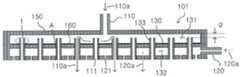
도 2는 본 발명의 제1실시예에 따른 다층 샤워헤드(101)를 설명하기 위한 도면;
도 3은 도 2의 필러시트(filler sheet, 160)를 설명하기 위한 도면;
도 4는 본 발명의 제2실시예에 따른 다층 샤워헤드(101)를 설명하기 위한 도면;
도 5는 본 발명의 제3실시예에 따른 다층 샤워헤드(201)를 설명하기 위한 도면;
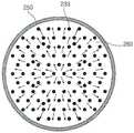
도 6은 도 5의 분리격판(230)을 위에서 내려다 본 도면;
도 7은 본 발명의 제4실시예에 따른 다층 샤워헤드(201')를 설명하기 위한 도면이다.
<부호의 설명>
10, 20, 110, 120, 210: 기체주입관
11, 21, 111, 121, 211: 기체배출구
30, 130, 230: 분리격판
31, 131, 231: 상부공간
32, 132, 232: 하부공간
33, 133, 233, 233': 기체안내관
50, 150, 250: 몸체
100, 101, 201: 다층 샤워헤드
160, 260: 필러시트
160a: 관통구멍1 is a view for explaining a conventional
2 is a view for explaining a
FIG. 3 is a view for explaining a
4 is a view for explaining a
5 is a view for explaining a
FIG. 6 is a top view of the
7 is a view for explaining the multilayer showerhead 201 'according to the fourth embodiment of the present invention.
<Description of Symbols>
10, 20, 110, 120, 210: gas injection tube
11, 21, 111, 121, 211: gas outlet
30, 130, 230: separation diaphragm
31, 131, 231: upper space
32, 132, 232: Lower space
33, 133, 233, 233 ': gas guide pipes
50, 150, 250: body
100, 101, 201: Multi-layer shower head
160, 260: filler sheet
160a: Through hole
이하에서, 본 발명의 바람직한 실시예를 첨부한 도면들을 참조하여 상세히 설명한다. 아래의 실시예는 본 발명의 내용을 이해하기 위해 제시된 것일 뿐이며 당 분야에서 통상의 지식을 가진 자라면 본 발명의 기술적 사상 내에서 많은 변형이 가능할 것이다. 따라서 본 발명의 권리범위가 이러한 실시예에 한정되는 것으로 해석돼서는 안 된다.Hereinafter, preferred embodiments of the present invention will be described in detail with reference to the accompanying drawings. The following embodiments are merely provided to understand the contents of the present invention, and those skilled in the art will be able to make many modifications within the technical scope of the present invention. Therefore, the scope of the present invention should not be construed as being limited to these embodiments.
도 2는 본 발명의 제1실시예에 따른 다층 샤워헤드(101)를 설명하기 위한 도면으로서, 여러기체를 동시에 분사할 수 있는 경우를 설명하기 위한 것이다. 도 2에 도시된 바와 같이, 다층 샤워헤드(101)는 몸체(150)의 내부 빈공간이 윗판과 아랫판 사이에 설치되는 분리격판(130)에 의해 상하공간(131, 132)으로 분리되며, 상부공간(131)에는 제1기체주입관(110)이 설치되고, 하부공간(132)에는 제2기체주입관(120)이 설치된다.Fig. 2 is a view for explaining the
분리격판(130)에는 하부공간(132)을 통과하여 몸체(150)의 아랫판을 관통하도록 기체안내관(133)이 끼워지며, 따라서 기체안내관(133)의 아래쪽 말단부는 제1기체배출구(111)를 이룬다. 몸체(150)의 아랫판에는 제1기체배출구(111)와 중첩되지 않는 위치에 제2기체배출구(121)로서의 역할을 하는 관통구멍이 형성된다.The lower end of the
이러한 구성에 따르면, 제1기체주입관(110)을 통하여 상부공간(131)으로 유입되는 제1기체(110a)는 기체안내관(133)에 의한 제1기체배출구(111)를 통하여 샤워헤드(101)의 하방으로 분사되고, 제2기체주입관(120)을 통하여 하부공간(132)으로 유입되는 제2기체(120a)는 제2기체배출구(121)를 통하여 샤워헤드(101)의 하방으로 분사됨으로써, 샤워헤드(101)를 통하여 공정챔버 내에 복수개의 기체가 독립적으로 동시에 또는 이시에 제공된다.The
이 때 분리격판(130)과 기체안내관(133)의 사이에 틈새(A)가 존재하게 되면, 상부공간(131)에 머물던 제1기체(110a)가 하부공간(132)으로 원하지 않게 유입되어 샤워헤드(101)에서 분사되기 전에 이미 하부공간(132)에서 제1기체(110a)와 제2기체(110b)의 혼합이 원하지 않게 이루어져 공정 레시피(recipe)에 맞지 않게 되는 문제가 발생할 수 있으므로, 분리격판(130)과 기체안내관(133) 사이의 틈새(A)를 밀봉하기 위하여 분리격판(130) 상에 필러시트(160)를 설치한다.At this time, if there is a gap A between the
도 3은 도 2의 필러시트(filler sheet, 160)를 설명하기 위한 도면이다. 도 2와 결부하여 도 3을 참조하면, 필러시트(160)는 70∼90 중량%의 니켈과 1∼10 중량%의 붕소를 포함하는 40∼70um 두께의 니켈 기반 합금으로 이루어지는 것이 바람직하며, 기체안내관(133)이 설치되어 있는 부위에 대응하여 관통구멍(160a)이 형성되어 있다. 관통구멍(160a)은 고출력 레이저 조사나 습식에칭 등을 통해서 형성될 수 있다.FIG. 3 is a view for explaining a
분리격판(130) 상에 필러시트(160)를 올려놓은 후에 기체안내관(133)을 분리격판(130)에 끼워넣고 950 ∼ 1200℃ 및 10-1 ∼ 10-2 torr의 조건에서 브레이징(brazing) 처리하면 필러시트(160)가 용융되는 과정에서 젖음성과 모세관 현상을 통하여 기체안내관(133)과 분리격판(130) 사이의 틈새(A)로 스며들어 틈새(A)가 밀봉 접합된다.After the
필러시트(160)는 다양한 가스에 대한 내식성이 강해야 하므로 이렇게 니켈 합금을 사용하는 것이 바람직하다. 유동성 부여를 위한 붕소량에 따라 약간씩 용융점이 변할 수는 있다. 필러시트(160)의 두께가 너무 두꺼우면 유동성 브레이징 처리시에 유동성 확보에 어려움이 있을 수 있고, 너무 얇으면 틈새(A)를 메우기에 충분치 않을 수 있으므로 이와 같이 적당한 두께가 고려되어야 한다. 그리고 브레이징 온도가 너무 높으면 몸체(150)의 기타 부위가 열처리에 의해 손상될 수 있으므로 진공환경을 만들어 브레이징 온도를 상기와 같이 저하시키는 것이 바람직하다.Since the
이러한 필러시트(160)를 사용하지 않고 디스펜서(dispenser)나 주사기를 사용하여 틈새(A)에 필러(filler)를 주입하여 밀봉 접합되도록 하는 것은 매우 정교한 작업을 반복해야 하기 때문에 시간과 노력면에서 바람직하지 못하고 필러량의 국부적인 가감에 따라 접합부의 신뢰도가 떨어지고 표면 형상 또한 매끄럽지 못하다는 문제가 있다. 그리고 필러시트(180)를 본 발명에서와 같이 구멍이 뚫려 있는 시트(sheet) 형태가 아니라 틈새(A)에 얹힐 수 있는 링(ring) 형상의 것을 일일이 복수개로 만들어 기체안내관(133)의 외주면에 얹은 후에 고온 진공로에서 브레이징(brazing) 처리하여 틈새(A)를 접합시키는 방법도 마찬가지의 단점이 있다.In order to fill the gap A with a filler by using a dispenser or a syringe without using the
이와 같이 본 발명은 틈새(A) 부위에 일일이 브레이징 필러액(바인더와 페이스트의 혼합액)을 도포하거나 링(ring) 형태의 시트를 복수개로 만들어 기체안내관(133)마다 하나씩 올려놓은 후에 브레이징 처리하는 방법을 사용하는 것이 아니라, 기체안내관(133)에 대응되는 관통구멍(160a)이 형성된 한 장의 시트(sheet)를 분리격판(130) 상에 올려놓고 브레이징 처리하기 때문에 샤워헤드(101)의 제작이 매우 간단하고 신뢰성있게 이루어진다.As described above, according to the present invention, the brazing filler liquid (mixed liquid of the binder and the paste) is individually applied to the gap A or a plurality of rings-shaped sheets are placed on the
도 4는 본 발명의 제2실시예에 따른 다층 샤워헤드(101)를 설명하기 위한 도면으로서, 도 2의 기체안내관(133)을 개량한 것이다. 도 2의 경우 상부공간(131)으로 유입되는 제1기체(110a)는 위에서 밑으로 제공되기 때문에 그 종방향으로의 방향성에 의해 사방의 옆으로 넓게 퍼지지 못하게 되어, 샤워헤드(101)의 가장자리에서의 기체 분사량이 가운데에 비해 작아지게 된다. 따라서 도 4에 도시된 바와 같이 기체안내관(133)의 윗단(t)이 분리격판(130)의 위로 돌출되도록 하여 기체안내관(133)과 몸체(150)의 윗면 사이의 틈(g)을 좁게 함으로써 이 부분에서의 유속이 빨라지게 하여 베르누이 정리에 의하여 기체가 옆으로 많이 확산될 수 있도록 하는 것이 바람직할 수 있다.Fig. 4 is a view for explaining the
기체안내관(133)과 몸체(150)의 윗면 사이의 틈(g)이 너무 크면 기체가 충분히 횡방향으로 확산되기 전에 기체안내관(133)을 통하여 주로 중앙부에서 하부공간(130)으로 유입되기 쉽고, 틈(g)이 너무 작으면 기체의 횡방향 흐름이 너무 방해를 받아 공정 균일성이 오히려 떨어지고 와류로 인한 파티클 발생 문제가 생기기 쉬우므로 적절한 선택이 필요하다.If the gap g between the
제2실시예의 경우에는 기체안내관(133)의 돌출윗단(t)에 기체가 부딪혀 와류가 형성되기 때문에 틈새(A)가 있는 경우 기체가 밑으로 새는 현상이 더 두드러지게 나타나 문제가 더 심각하다. 따라서 본 발명에 따른 필러시트(160)의 설치 필요성이 더 요구된다.In the case of the second embodiment, since the gas bumps against the protruding upper end t of the
도 5는 본 발명의 제3실시예에 따른 다층 샤워헤드(201)를 설명하기 위한 도면으로서, 대면적에 대해 기체를 균일하게 분사하도록 하는 경우를 설명하기 위한 것이다. 그리고 도 6은 도 5의 분리격판(230)을 위에도 내려다 본 도면이다.FIG. 5 is a view for explaining a
도 5 및 도 6을 참조하면, 다층 샤워헤드(201)는 몸체(250)의 내부 빈공간이 윗판과 아랫판 사이에 설치되는 분리격판(230)에 의해 상하공간(231, 232)으로 분리되며, 상부공간(231)에는 기체주입관(210)이 설치된다. 몸체(250)의 아랫판에는 복수개의 기체배출구(211)가 형성되며, 분리격판(230)에는 상부공간(231)과 하부공간(232)이 연통되도록 기체안내관(233)이 관통 삽입된다. 이 때 기체안내관(233)의 윗단(t)은 도 4에서 설명한 바와 같은 이유로 분리격판(230)의 위로 돌출되도록 설치된다. 물론 기체안내관(233)의 윗단(t)이 분리격판(230)의 위로 돌출되지 않을 수도 있다.5 and 6, the
제3실시예에 따르면, 기체주입관(210)을 통하여 상부공간(231)으로 유입되는 기체는 기체안내관(233)의 돌출부(t)에 의해 횡방향으로 넓은 범위까지 순식간에 골고루 확산되면서 기체안내관(233)을 통하여 하부공간(232)으로 유입되어 분산된 후 기체배출구(211)를 통하여 샤워헤드(100)의 하방으로 대면적에 대해서 골고루 분사된다.According to the third embodiment, the gas introduced into the
이 경우도 도 2의 경우와 마찬가지로 분리격판(230)과 기체안내관(233)의 사이에 틈새(A)가 존재하게 되면, 상부공간(231)에서 횡방향으로 확산하던 기체가 중간에서 원하지 않게 밑으로, 즉 하부공간(232)으로 새어버리게 되어 횡방향으로의 확산량이 작아지게 됨으로써 샤워헤드(201)의 중앙부를 통한 기체분사량이 더 많아지는 문제가 발생하게 된다. 따라서 이를 방지하기 위하여 제1실시예에서와 같은 필러시트(260)를 분리격판(230) 상에 설치한다.Also in this case, if there is a gap A between the separating
도 7은 본 발명의 제4실시예에 따른 다층 샤워헤드(201')를 설명하기 위한 도면으로서 두 개의 샤워헤드가 중첩되어 설치되는 경우를 설명하기 위한 것이다.FIG. 7 is a view for explaining a multi-layer showerhead 201 'according to a fourth embodiment of the present invention, in which two showerheads are overlapped and installed.
도 7을 참조하면, 상부 샤워헤드(201)는 도 5의 경우와 근본적으로 같으며 단지 기체배출구(211)가 관형태로 밑으로 연장되어 하부 샤워헤드(201')를 관통하도록 설치되며, 하부 샤워헤드(201') 역시 도 5의 경우와 근본적으로 동일하나 단지 기체안내관(233')이 하부 샤워헤드(201')의 윗판, 분리격판, 및 아랫판을 관통하도록 더 설치되는 점이 다르다.Referring to FIG. 7, the
실시예 4의 경우에도 기체안내관(233')이 관통하는 부위에 틈새가 존재하면 바람직하지 않기 때문에 앞서와 마찬가지로 필러시트(360)를 샤워헤드 몸체의 윗판, 분리격판, 아랫판에 올려놓고 브레이징 처리하여 밀봉시킨다.Also in the case of Embodiment 4, it is not preferable if there is a gap in the portion where the gas guide pipe 233 'penetrates. Therefore, the
산업상 이용가능성Industrial availability
상술한 바와 같이 본 발명의 경우는, 틈새(A) 부위에 일일이 브레이징 필러액(바인더와 페이스트의 혼합액)을 도포하거나 링(ring) 형태의 시트를 복수개로 만들어 기체안내관(133, 233)마다 하나씩 올려놓은 후에 브레이징 처리하는 방법을 사용하는 것이 아니라, 기체안내관(133, 233)에 대응되는 관통구멍(160a)이 형성된 한 장의 시트(sheet)를 분리격판(130, 230) 등에 올려놓고 브레이징 처리하기 때문에 샤워헤드(101, 201, 201'))의 제작이 매우 간단하고 신뢰성있게 이루어진다.As described above, in the case of the present invention, the brazing filler liquid (mixed liquid of the binder and the paste) is applied to the clearance A region individually, or a plurality of rings-shaped sheets are formed to cover the
Claims (12)
Translated fromKorean상기 상부공간에 설치되는 제1기체주입관;
상기 하부공간에 설치되는 제2기체주입관;
상기 몸체의 아랫판에 형성되는 기체배출구;
상기 몸체의 분리격판 및 아랫판을 관통하도록 설치되는 기체안내관; 및
상기 기체안내관이 설치되어 있는 부위에 대응하도록 관통구멍이 형성되며, 상기 기체안내관이 통과하는 상기 분리격판 및 상기 아랫판에 얹혀진 상태에서 브레이징(brazing) 처리됨으로써 상기 기체안내관과 상기 기체안내관이 관통하는 상기 분리격판 및 상기 아랫판 사이의 틈새를 밀봉 접합하도록 설치되는 필러시트(filler sheet);를 포함하고,
상기 제1기체주입관을 통하여 상기 상부공간으로 유입되는 제1기체는 기체안내관에 의한 제1기체배출구를 통하여 하방으로 분사되고, 상기 제2기체주입관을 통하여 상기 하부공간으로 유입되는 제2기체는 제2기체배출구를 통하여 하방으로 분사되어, 상기 제1,2기체는 상기 몸체 내에서 혼합되지 않고 외부로 분사되는 다층 샤워헤드.A body in which an inner space is divided into an upper space and a lower space by a separation diaphragm provided between an upper plate and a lower plate;
A first gas injection pipe installed in the upper space;
A second gas injection pipe installed in the lower space;
A gas outlet formed on the lower plate of the body;
A gas guide pipe installed to pass through the separating diaphragm and the lower plate of the body; And
A through hole is formed corresponding to a portion where the gas guide pipe is installed and a brazing process is performed in a state of being placed on the separating partition plate and the lower plate through which the gas guide pipe passes, And a filler sheet installed to sealingly bond a gap between the separating partition plate and the lower plate,
The first gas introduced into the upper space through the first gas injection pipe is injected downward through the first gas discharge port by the gas guide pipe and the second gas injected through the second gas injection pipe into the lower space through the second gas injection pipe, Wherein the gas is injected downward through the second gas discharge port so that the first and second gases are injected outside without being mixed in the body.
상기 기체안내관의 윗단이,
상기 분리격판의 위로 돌출되는 다층 샤워헤드.The method of claim 11,
The upper end of the gas guide tube
Layer shower head protruding above the separation diaphragm.
Applications Claiming Priority (5)
| Application Number | Priority Date | Filing Date | Title |
|---|---|---|---|
| KR20110049102 | 2011-05-27 | ||
| KR1020110049102 | 2011-05-27 | ||
| KR20110050670 | 2011-05-27 | ||
| KR1020110050670 | 2011-05-27 | ||
| PCT/KR2012/004125WO2012161536A2 (en) | 2011-05-24 | 2012-05-24 | Multi-layer shower head and method for sealing same |
Related Parent Applications (1)
| Application Number | Title | Priority Date | Filing Date |
|---|---|---|---|
| KR1020137019237ADivisionKR20130115330A (en) | 2011-05-24 | 2012-05-24 | Showerhead having multi-layer and method for sealing the same |
Publications (2)
| Publication Number | Publication Date |
|---|---|
| KR20150091520A KR20150091520A (en) | 2015-08-11 |
| KR101947519B1true KR101947519B1 (en) | 2019-02-14 |
Family
ID=47217916
Family Applications (2)
| Application Number | Title | Priority Date | Filing Date |
|---|---|---|---|
| KR1020157018817AActiveKR101947519B1 (en) | 2011-05-27 | 2012-05-24 | Showerhead having multi-layer and method for sealing the same |
| KR1020137019237ACeasedKR20130115330A (en) | 2011-05-24 | 2012-05-24 | Showerhead having multi-layer and method for sealing the same |
Family Applications After (1)
| Application Number | Title | Priority Date | Filing Date |
|---|---|---|---|
| KR1020137019237ACeasedKR20130115330A (en) | 2011-05-24 | 2012-05-24 | Showerhead having multi-layer and method for sealing the same |
Country Status (2)
| Country | Link |
|---|---|
| KR (2) | KR101947519B1 (en) |
| WO (1) | WO2012161536A2 (en) |
Citations (2)
| Publication number | Priority date | Publication date | Assignee | Title |
|---|---|---|---|---|
| KR100752622B1 (en)* | 2006-02-17 | 2007-08-30 | 한양대학교 산학협력단 | Remote Plasma Generator |
| KR100923453B1 (en)* | 2007-09-21 | 2009-10-27 | 주식회사 피에조닉스 | Semiconductor device fabrication equipment with showerhead |
Family Cites Families (2)
| Publication number | Priority date | Publication date | Assignee | Title |
|---|---|---|---|---|
| US6073577A (en)* | 1998-06-30 | 2000-06-13 | Lam Research Corporation | Electrode for plasma processes and method for manufacture and use thereof |
| KR101064210B1 (en)* | 2009-06-01 | 2011-09-14 | 한국생산기술연구원 | Shower head for membrane deposition vacuum equipment |
- 2012
- 2012-05-24KRKR1020157018817Apatent/KR101947519B1/enactiveActive
- 2012-05-24WOPCT/KR2012/004125patent/WO2012161536A2/enactiveApplication Filing
- 2012-05-24KRKR1020137019237Apatent/KR20130115330A/ennot_activeCeased
Patent Citations (2)
| Publication number | Priority date | Publication date | Assignee | Title |
|---|---|---|---|---|
| KR100752622B1 (en)* | 2006-02-17 | 2007-08-30 | 한양대학교 산학협력단 | Remote Plasma Generator |
| KR100923453B1 (en)* | 2007-09-21 | 2009-10-27 | 주식회사 피에조닉스 | Semiconductor device fabrication equipment with showerhead |
Also Published As
| Publication number | Publication date |
|---|---|
| WO2012161536A3 (en) | 2013-03-21 |
| WO2012161536A2 (en) | 2012-11-29 |
| KR20130115330A (en) | 2013-10-21 |
| KR20150091520A (en) | 2015-08-11 |
Similar Documents
| Publication | Publication Date | Title |
|---|---|---|
| KR102700194B1 (en) | Substrate processing apparatus | |
| US8944309B2 (en) | Organic vapor jet print head with solder joint | |
| JP2022046791A (en) | Liquid delivery system | |
| CN106609363A (en) | Semiconductor manufacturing system including deposition apparatus | |
| JP2023171803A (en) | UM base configuration | |
| KR100831198B1 (en) | Welding shower head | |
| CN102738105A (en) | Semiconductor device and method of manufacturing the same | |
| CN102597310A (en) | Evaporator | |
| TWI730532B (en) | Chamber air inlet structure and reaction chamber | |
| WO2011077641A1 (en) | Epitaxial growing apparatus and method for manufacturing epitaxial growing apparatus | |
| KR101947519B1 (en) | Showerhead having multi-layer and method for sealing the same | |
| TWM496228U (en) | Wafer tray structure | |
| JP2018534728A5 (en) | ||
| TW201138978A (en) | Shower head and apparatus for manufacturing semiconductor substrate having the same | |
| KR101542599B1 (en) | Showerhead and showerhead structure for manufacturing an electronic device having a diffusion fin | |
| WO2003087559A1 (en) | Combustor of gas turbine | |
| KR20210020436A (en) | Bonding component | |
| KR20100099488A (en) | Shower head using gas injection module and manufacturing method of it | |
| JP4218899B2 (en) | Substrate holder provided with electrostatic chuck and method for manufacturing the same | |
| CN107818944A (en) | Use the method for the recess of tungsten filling substrate | |
| CN114114858B (en) | A glue nozzle seat bearing device and glue coating and developing equipment | |
| CN116569382A (en) | Die coater gasket and die coater for coating active material on current collector of secondary battery | |
| CN108609574A (en) | Enclosed structure, method of making same and device | |
| CN116581055A (en) | Reactor cooling system | |
| CN109440082B (en) | Source bottle capable of preventing precursor liquid from dripping into pipeline or cavity |
Legal Events
| Date | Code | Title | Description |
|---|---|---|---|
| A107 | Divisional application of patent | ||
| PA0104 | Divisional application for international application | Comment text:Divisional Application for International Patent Patent event code:PA01041R01D Patent event date:20150713 Application number text:1020137019237 Filing date:20130719 | |
| PG1501 | Laying open of application | ||
| A201 | Request for examination | ||
| PA0201 | Request for examination | Patent event code:PA02012R01D Patent event date:20170524 Comment text:Request for Examination of Application | |
| E902 | Notification of reason for refusal | ||
| PE0902 | Notice of grounds for rejection | Comment text:Notification of reason for refusal Patent event date:20170610 Patent event code:PE09021S01D | |
| E902 | Notification of reason for refusal | ||
| PE0902 | Notice of grounds for rejection | Comment text:Notification of reason for refusal Patent event date:20180329 Patent event code:PE09021S01D | |
| E701 | Decision to grant or registration of patent right | ||
| PE0701 | Decision of registration | Patent event code:PE07011S01D Comment text:Decision to Grant Registration Patent event date:20181211 | |
| PR0701 | Registration of establishment | Comment text:Registration of Establishment Patent event date:20190207 Patent event code:PR07011E01D | |
| PR1002 | Payment of registration fee | Payment date:20190208 End annual number:3 Start annual number:1 | |
| PG1601 | Publication of registration | ||
| PR1001 | Payment of annual fee | Payment date:20220207 Start annual number:4 End annual number:4 | |
| PR1001 | Payment of annual fee | Payment date:20230102 Start annual number:5 End annual number:5 | |
| PR1001 | Payment of annual fee | Payment date:20241223 Start annual number:7 End annual number:7 |