KR101942028B1 - LED lighting apparatus - Google Patents
LED lighting apparatusDownload PDFInfo
- Publication number
- KR101942028B1 KR101942028B1KR1020110095817AKR20110095817AKR101942028B1KR 101942028 B1KR101942028 B1KR 101942028B1KR 1020110095817 AKR1020110095817 AKR 1020110095817AKR 20110095817 AKR20110095817 AKR 20110095817AKR 101942028 B1KR101942028 B1KR 101942028B1
- Authority
- KR
- South Korea
- Prior art keywords
- inrush current
- capacitor
- power
- unit
- led
- Prior art date
- Legal status (The legal status is an assumption and is not a legal conclusion. Google has not performed a legal analysis and makes no representation as to the accuracy of the status listed.)
- Active
Links
Images


Classifications
- H—ELECTRICITY
- H05—ELECTRIC TECHNIQUES NOT OTHERWISE PROVIDED FOR
- H05B—ELECTRIC HEATING; ELECTRIC LIGHT SOURCES NOT OTHERWISE PROVIDED FOR; CIRCUIT ARRANGEMENTS FOR ELECTRIC LIGHT SOURCES, IN GENERAL
- H05B45/00—Circuit arrangements for operating light-emitting diodes [LED]
- H05B45/30—Driver circuits
- H05B45/395—Linear regulators
- H—ELECTRICITY
- H05—ELECTRIC TECHNIQUES NOT OTHERWISE PROVIDED FOR
- H05B—ELECTRIC HEATING; ELECTRIC LIGHT SOURCES NOT OTHERWISE PROVIDED FOR; CIRCUIT ARRANGEMENTS FOR ELECTRIC LIGHT SOURCES, IN GENERAL
- H05B45/00—Circuit arrangements for operating light-emitting diodes [LED]
- H05B45/10—Controlling the intensity of the light
- H—ELECTRICITY
- H05—ELECTRIC TECHNIQUES NOT OTHERWISE PROVIDED FOR
- H05B—ELECTRIC HEATING; ELECTRIC LIGHT SOURCES NOT OTHERWISE PROVIDED FOR; CIRCUIT ARRANGEMENTS FOR ELECTRIC LIGHT SOURCES, IN GENERAL
- H05B45/00—Circuit arrangements for operating light-emitting diodes [LED]
- H05B45/30—Driver circuits
- H05B45/37—Converter circuits
- H—ELECTRICITY
- H05—ELECTRIC TECHNIQUES NOT OTHERWISE PROVIDED FOR
- H05B—ELECTRIC HEATING; ELECTRIC LIGHT SOURCES NOT OTHERWISE PROVIDED FOR; CIRCUIT ARRANGEMENTS FOR ELECTRIC LIGHT SOURCES, IN GENERAL
- H05B45/00—Circuit arrangements for operating light-emitting diodes [LED]
- H05B45/50—Circuit arrangements for operating light-emitting diodes [LED] responsive to malfunctions or undesirable behaviour of LEDs; responsive to LED life; Protective circuits
- H—ELECTRICITY
- H02—GENERATION; CONVERSION OR DISTRIBUTION OF ELECTRIC POWER
- H02H—EMERGENCY PROTECTIVE CIRCUIT ARRANGEMENTS
- H02H9/00—Emergency protective circuit arrangements for limiting excess current or voltage without disconnection
- H02H9/001—Emergency protective circuit arrangements for limiting excess current or voltage without disconnection limiting speed of change of electric quantities, e.g. soft switching on or off
- Y—GENERAL TAGGING OF NEW TECHNOLOGICAL DEVELOPMENTS; GENERAL TAGGING OF CROSS-SECTIONAL TECHNOLOGIES SPANNING OVER SEVERAL SECTIONS OF THE IPC; TECHNICAL SUBJECTS COVERED BY FORMER USPC CROSS-REFERENCE ART COLLECTIONS [XRACs] AND DIGESTS
- Y02—TECHNOLOGIES OR APPLICATIONS FOR MITIGATION OR ADAPTATION AGAINST CLIMATE CHANGE
- Y02B—CLIMATE CHANGE MITIGATION TECHNOLOGIES RELATED TO BUILDINGS, e.g. HOUSING, HOUSE APPLIANCES OR RELATED END-USER APPLICATIONS
- Y02B20/00—Energy efficient lighting technologies, e.g. halogen lamps or gas discharge lamps
- Y02B20/30—Semiconductor lamps, e.g. solid state lamps [SSL] light emitting diodes [LED] or organic LED [OLED]
Landscapes
- Circuit Arrangement For Electric Light Sources In General (AREA)
Abstract
Translated fromKorean
Description
Translated fromKoreanLED(Light Emitting Diode)를 구비한 LED 조명 장치에 관한다.The present invention relates to an LED lighting apparatus provided with an LED (Light Emitting Diode).
기술의 발전에 따라, 과거 인디케이터 등의 소전력 지시등용으로 밖에 사용되지 못하던 LED의 광효율이 실생활에 사용될 수 있을 만큼 향상되고 있다. 또한, LED는 다른 광원들과 달리 수은이 함유되지 않은 친환경 광원으로, 휴대 단말기용 백라이트, LCD TV용 백라이트, 차량용 램프, 및 일반 조명 등에 사용되는 차세대 광원으로 널리 각광을 받고 있다. 이에 따라, 지난 100여년 동안 조명의 주광원으로 사용되어 왔던 저전력 효율 특성을 갖는 백열등이나 수은 등의 환경 폐기물을 포함하고 있는 형광등이 LED 램프로 대체되기 시작하고 있다.With the development of the technology, the light efficiency of the LED, which has been used only for a small power indicator such as a past indicator, has been improved so that it can be used in real life. Unlike other light sources, LED is an eco-friendly light source that does not contain mercury, and is widely regarded as a next generation light source for backlight for portable terminals, backlight for LCD TVs, vehicle lamps, and general lighting. As a result, fluorescent lamps, including incandescent lamps and mercury, which have low power efficiency characteristics, which have been used as main light sources for lighting for the past 100 years, are beginning to be replaced by LED lamps.
그러나, LED 램프의 경우, 백열등이나 할로겐 램프 등을 그대로 대체하기에는 LED 램프와 안정기(ballast)와의 호환성 문제, 또는 LED 주변 회로 소자의 수명에 의한 LED 램프의 수명 단축 등의 해결하여야 할 문제가 있다.However, in the case of an LED lamp, there is a problem of compatibility between an LED lamp and a ballast to replace an incandescent lamp or a halogen lamp, or shortening the life of the LED lamp due to the lifetime of the LED peripheral circuit element.
본 발명의 적어도 하나의 실시예가 이루고자 하는 기술적 과제는 LED를 구비한 LED 조명 장치를 제공하는데 있다. 본 실시예가 해결하려는 기술적 과제는 상기된 바와 같은 기술적 과제들로 한정되지 않으며, 또 다른 기술적 과제들이 존재할 수 있다.SUMMARY OF THE INVENTION It is an object of at least one embodiment of the present invention to provide an LED lighting device with an LED. The technical problem to be solved by this embodiment is not limited to the above-described technical problems, and other technical problems may exist.
일 측면에 따르면, 상용 교류 전원을 안정기를 통해 공급함으로써 LED를 구동시키는 LED (light emitting diode) 조명 장치는 상기 안정기로부터 출력된 교류 전원을 승압하여 출력하는 전원 승압부; 상기 승압된 교류 전원을 직류 전원으로 정류하는 정류부; 상기 정류되는 동안 돌입 전류(inrush current)의 발생을 차단하는 돌입 전류 차단부; 및 상기 돌입 전류가 차단되어 공급된 직류 전원을 이용하여 상기 LED의 동작을 제어하는 LED 구동부를 포함한다.According to an aspect of the present invention, there is provided an LED (light emitting diode) lighting apparatus for driving an LED by supplying commercial AC power through a ballast, comprising: a power supply voltage up unit for boosting and outputting an AC power output from the ballast; A rectifying unit for rectifying the boosted AC power to a DC power; An inrush current cutoff unit for blocking an occurrence of an inrush current during the rectification; And an LED driver for controlling operation of the LED using the DC power supplied while the inrush current is interrupted.
다른 일 측면에 따르면, 상용 교류 전원을 안정기를 통해 공급함으로써 LED 조명 장치를 구동시키는 방법은 상기 안정기로부터 출력된 교류 전원을 승압하는 단계; 상기 승압된 교류 전원을 직류 전원으로 정류하는 단계; 상기 정류되는 동안 돌입 전류(inrush current)의 발생을 차단하는 단계; 및 상기 돌입 전류가 차단되어 공급된 직류 전원을 이용하여 상기 LED의 동작을 제어하는 단계를 포함한다.According to another aspect of the present invention, there is provided a method of driving an LED lighting apparatus by supplying commercial AC power through a ballast, comprising steps of: boosting an AC power output from the ballast; Rectifying the step-up AC power supply to a DC power supply; Blocking an occurrence of an inrush current during the rectification; And controlling the operation of the LED using the DC power supplied with the inrush current cut off.
또 다른 일 측면에 따르면, 공급된 상용 교류 전원을 이용하여 LED를 구동시키는 LED (light emitting diode) 조명 장치는 상기 LED 조명 장치의 구동을 안정시키기 위하여, 상기 공급된 상용 교류 전원을 소정 전압의 교류 전원으로 출력하는 안정기; 상기 안정기로부터 출력된 교류 전원을 승압하여 출력하는 전원 승압부; 상기 승압된 교류 전원을 직류 전원으로 정류하는 정류부; 및 상기 정류된 직류 전원을 이용하여 상기 LED의 동작을 제어하는 LED 구동부를 포함한다.According to another aspect of the present invention, there is provided an LED (light emitting diode) lighting apparatus for driving an LED using a supplied commercial AC power source, the apparatus comprising: A ballast for outputting power; A power supply step-up unit for stepping up the AC power outputted from the ballast and outputting the AC power; A rectifying unit for rectifying the boosted AC power to a DC power; And an LED driving unit for controlling operation of the LED using the rectified DC power.
또 다른 일 측면에 따르면, 상용 교류 전원을 안정기를 통해 공급함으로써 LED를 구동시키는 LED (light emitting diode) 조명 장치는 상기 안정기를 통해 공급된 교류 전원을 직류 전원으로 정류하는 정류부; 상기 정류된 직류 전원에서 돌입 전류(inrush current)가 발생된 경우, 상기 발생된 돌입 전류를 차단하는 돌입 전류 차단부; 및 상기 돌입 전류가 차단되어 공급된 직류 전원을 이용하여 상기 LED의 동작을 제어하는 LED 구동부를 포함한다.According to another aspect of the present invention, an LED (light emitting diode) lighting device for driving an LED by supplying commercial AC power through a ballast includes a rectifier for rectifying the AC power supplied through the ballast to a DC power supply; An inrush current cutoff unit for blocking the generated inrush current when an inrush current is generated in the rectified DC power supply; And an LED driver for controlling operation of the LED using the DC power supplied while the inrush current is interrupted.
또 다른 일 측면에 따르면, 회로 장치는 회로 장치의 구동을 안정시키기 위하여, 공급된 상용 교류 전원을 소정 전압의 교류 전원으로 출력하는 안정기; 상기 안정기로부터 출력된 상기 소정 전압의 교류 전원을 승압하는 전원 승압부; 상기 승압된 교류 전원을 직류 전원으로 정류하는 정류부; 상기 정류되는 동안 돌입 전류(inrush current)의 발생을 차단하는 돌입 전류 차단부; 및 상기 돌입 전류가 차단되어 공급된 직류 전원을 이용하여 상기 회로 장치의 구동을 제어하는 구동부를 포함한다.According to another aspect of the present invention, there is provided a circuit device comprising: a ballast for outputting a supplied commercial AC power to an AC power supply of a predetermined voltage for stabilizing driving of a circuit device; A power supply voltage step-up unit for stepping up the AC power of the predetermined voltage outputted from the ballast; A rectifying unit for rectifying the boosted AC power to a DC power; An inrush current cutoff unit for blocking an occurrence of an inrush current during the rectification; And a driving unit for controlling the driving of the circuit device using the DC power supplied with the inrush current cut off.
상기된 바에 따르면, LED 조명 장치의 안정기(ballast)의 출력을 승압시키는 전압 승압 회로를 구비함으로써 안정기의 사용에 따른 LED의 광량이 저하되는 현상을 방지할 수 있다. 또한, 전압 승압 회로에서 승압된 출력을 공급함으로써 정류 회로의 커패시터의 용량을 감소시키거나 또는 종류를 변경시킬 수 있으므로, LED 조명 장치의 수명을 연장시키거나, 내부 회로의 공간을 확보할 수 있다. 나아가서, 돌입 전류 차단 회로에서 돌입 전류를 차단시킴으로써, 돌입 전류에 의한 안정기, LED 드라이버, LED 등의 회로의 데미지를 방지할 수 있다.According to the above, since the voltage booster circuit for boosting the output of the ballast of the LED lighting apparatus is provided, it is possible to prevent the light amount of the LED from being lowered due to the use of the ballast. Further, since the capacity of the capacitor of the rectifying circuit can be reduced or changed by supplying the boosted output from the voltage step-up circuit, the life of the LED lighting device can be extended or the space of the internal circuit can be ensured. Further, by blocking the inrush current in the inrush current shutoff circuit, it is possible to prevent damage to the circuit such as the ballast, the LED driver, and the LED by the inrush current.
즉, 종래의 할로겐 램프, LED 램프의 회로의 호환성 문제를 해결할 수 있다.That is, it is possible to solve the compatibility problem of the circuit of the conventional halogen lamp and the LED lamp.
도 1은 본 발명의 일 실시예에 따른 LED 조명 장치(1)의 회로도이다.
도 2는 본 발명의 일 실시예에 따라 안정기(20)에서 출력된 소정 전압의 교류 전원을 도시한 도면이다.
도 3은 본 발명의 일 실시예에 따른 전원 승압부(30)를 도시한 도면이다.
도 4a 및 도 4b는 본 발명의 일 실시예에 따른 전원 승압부(30)의 승압 결과를 도시한 도면이다.
도 5는 본 발명의 일 실시예에 따른 돌입 전류 차단부(50)를 도시한 도면이다.
도 6은 본 발명의 일 실시예에 따른 LED 조명 장치(1)를 구동시키는 방법의 흐름도이다.1 is a circuit diagram of an
2 is a view showing an AC power source of a predetermined voltage outputted from the
3 is a diagram illustrating a power supply
4A and 4B are diagrams showing the step-up results of the power-supply step-up
5 is a diagram illustrating a rush
6 is a flowchart of a method of driving the
이하에서는 도면을 참조하여 본 발명의 실시예들을 상세히 설명하도록 하겠다.Hereinafter, embodiments of the present invention will be described in detail with reference to the drawings.
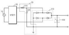
도 1은 본 발명의 일 실시예에 따른 LED 조명 장치(1)의 회로도이다. 도 1을 참고하면, LED 조명 장치(1)는 일종의 LED 램프로써, 전원 공급부(10), 안정기(20), 전원 승압부(30), 정류부(40), 돌입 전류 차단부(50), LED 구동부(60) 및 광원부(70)를 포함한다.1 is a circuit diagram of an
도 1에 도시된 LED 조명 장치(1)에는 본 실시예와 관련된 구성 요소들만이 도시되어 있다. 따라서, 도 1에 도시된 구성요소들 외에 다른 범용적인 구성 요소들이 더 포함될 수 있음을 본 실시예와 관련된 기술분야에서 통상의 지식을 가진 자라면 이해할 수 있다.Only the components related to the present embodiment are shown in the
전원 공급부(10)는 LED 조명 장치(1)에 상용 교류 전원을 인가한다. 상용 교류 전원은 가정 또는 기업 등에 제공되는, 시간에 따라 크기와 방향이 주기적으로 변하는 일반적인 교류 전원을 의미한다. 국내에서, 상용 교류 전원의 배전 전압은 220[V], 60[Hz]의 교류 전압을 표준 전압으로 공급하여 사용하고 있다. 그러나 본 실시예는 이와 같은 배전 전압에 한정되지 않는다는 것을 본 실시예가 속하는 기술분야에서 통상의 지식을 가진 자라면 이해할 수 있다.The
본 실시예에 따른 LED 조명 장치(1)는 전원 공급부(10)를 통해 공급된 이와 같은 상용 교류 전원을 이용하여 LED(light emitting diode)를 발광시킴으로써 LED를 조명으로 이용하는 장치이다.The
안정기(ballast)(20)는 LED 조명 장치(1)의 구동을 안정시키기 위하여, 공급된 상용 교류 전원을 소정 전압의 교류 전원으로 출력한다. 예를 들어, 안정기(20)는 LED 조명 장치(1)의 구동을 안정시키기 위하여 220[V]로 공급된 상용 교류 전원을 변환하여 12[V]의 교류 전원으로 출력할 수 있다.The
본 실시예에 따른 안정기(20)는 일반적으로 사용되고 있는 전자식 또는 기계식 안정기로써, 당해 기술분야에서 통상의 지식을 가진 자에게 자명하므로, 안정기(20)의 구체적 회로 구성, 동작 등에 대한 자세한 설명은 생략하도록 하겠다.Since the
이 때, 안정기(20)로부터 출력된 교류 전원은 구형파로 구성된 정현파(sine wave) 형태의 교류 전원이다. 이에 대해서는 도 2를 참고하여 설명하도록 하겠다.At this time, the alternating current power output from the
도 2는 본 발명의 일 실시예에 따라 안정기(20)에서 출력된 소정 전압의 교류 전원을 도시한 도면이다. 도 2를 참고하면, 앞서 설명한 바와 같이, 안정기(20)에서 출력된 교류 전원은 구형파로 구성된 정현파(sine wave) 형태이다.2 is a view showing an AC power source of a predetermined voltage outputted from the
종래에, 할로겐 램프 또는 LED 램프 등은 상용 교류 전원과 할로겐 광원 또는 LED 광원 사이에 이와 같은 안정기(20)를 구비함으로써, 도 2에 도시된 구형파로 구성된 정형파 형태의 AC 12V를 이용하였다. 여기서, 할로겐 램프는 저항 성분의 필라멘트를 사용하기에 이와 같은 안정기(20)의 출력과 호환 문제가 발생되지 않았다.Conventionally, a halogen lamp, an LED lamp, or the like has been provided with the
하지만, 종래의 LED 램프는 LED의 구동을 위한 LED 드라이버(driver)가 함께 구비될 수 있다. LED 드라이버는 효율(발열)과 실장성을 고려하여 스위칭 방식을 주로 사용하기에 LED 드라이버의 자체적인 스위칭 주파수를 갖는다. 또한, LED 드라이버의 구성 소자들로 인해 커패시턴스(Capacitances) 또는 인덕턴스(Inductances)를 갖는 부하로 동작될 수 있으므로, 특히 안정기(20)와의 호환성 문제가 발생할 수 있다.However, a conventional LED lamp may be provided with an LED driver for driving the LED. The LED driver has its own switching frequency because it mainly uses the switching method in consideration of efficiency (heat generation) and mounting property. In addition, since the components of the LED driver can be operated with a load having capacitances or inductances, compatibility problems with the
또한, 앞서 설명한 바와 같이, 안정기(20)에서 출력된 교류 전원은 구형파로 구성된 정현파(sine wave) 형태이므로, 낮은 전압을 갖는 영역(210)에서는 LED의 VF근처까지 전압이 하강할 수 있어 전류량 감소에 따른 LED의 꺼짐 현상이 발생될 수 있다. 바꾸어 말하면, LED의 광량 저하 현상이 발생될 수 있다.As described above, since the AC power source output from the
이에 대하여, 본 실시예에 따른 LED 조명 장치(1)는 종래의 안정기(20)와의 호환성 문제 또는 광량 저하 현상 등을 해결하고자 전원 승압부(30)를 구비한다.On the other hand, the
다시 도 1을 참고하면, 전원 승압부(boosting unit)(30)는 안정기(20)로부터 출력된 소정 전압의 교류 전원을 승압하여 출력한다. 이 때, 전원 승압부(30)는 인덕터 및 커패시터의 조합에 의한 공진 현상을 이용하여 안정기(20)로부터 출력된 교류 전원을 승압한다.Referring again to FIG. 1, the
정류부(40)는 승압된 교류 전원을 직류 전원으로 정류한다. 정류부(40)는 브릿지 정류기(410)를 포함한다. 또한, 정류부(40)는 전원 승압부(30)에서 승압된 교류 전원에 기초하여, 정류부(30)에 구비될 커패시터(420)의 용량, 커패시터(420)의 종류 등이 결정된다. 정류부(40)에 대해서는 이하 해당 부분에서 보다 상세히 설명하도록 하겠다.The rectifying unit (40) rectifies the boosted AC power to DC power. The
도 3은 본 발명의 일 실시예에 따른 전원 승압부(30)를 도시한 도면이다. 도 3을 참고하면, 본 실시예의 전원 승압부(30)는 안정기(20)와 접지되어 연결된 인덕터(310) 및 커패시터(320)에 의한 공진 현상을 이용하여 승압한다. 다만, 본 실시예에 따른 전원 승압부(30)의 회로 구성은 이에 한정되지 않고, 공진 현상을 이용하여 안정기(20)로부터 출력된 교류 전원을 승압할 수 있는 다른 회로 구성으로 변형될 수 있음을 당해 기술분야에서 통상의 지식을 가진 자라면 이해할 수 있다.3 is a diagram illustrating a power supply
도 4a 및 도 4b는 본 발명의 일 실시예에 따른 전원 승압부(30)의 승압 결과를 도시한 도면이다.4A and 4B are diagrams showing the step-up results of the power-supply step-up
우선, 도 4a를 참고하면, 전원 승압부(30)가 없는 종래의 경우의 구형파(401)와, 전원 승압부(30)가 구비된 경우 전원 승압부(30)에서 출력된 구형파(402)가 비교되어 도시되어 있다.4A, a
비교하여 보면, 전원 승압부(30)가 구비되어 LC 회로의 공진 현상에 의해 출력 전압이 상승됨으로써 종래의 구형파(401)의 전압 보다 높은 출력 전압을 갖는 구형파(402)를 얻을 수 있다.In comparison, the power supply voltage step-
정류부(40)는 구형파(401 또는 402)를 직류 전원(403 또는 404)으로 정류한다. 여기서, 종래의 직류 전원(403)은 본 실시예에 따라 정류된 직류 전원(404)과 비교할 때, 낮은 전압으로 정류된다.The rectifying
다음으로, 도 4b를 참고하면, 도 4b는 도 4a와 비교하여 전원 승압부(30)의 LC 회로의 공진이 충분히 큰 경우에 대한 도면이다.Next, referring to FIG. 4B, FIG. 4B is a diagram for a case where the resonance of the LC circuit of the power supply voltage up
전원 승압부(30)가 없는 종래의 경우의 구형파(401)와, 전원 승압부(30)가 구비된 경우 전원 승압부(30)에서 출력된 구형파(405)가 비교되어 도시되어 있다.The
비교하여 보면, 도 4a와 마찬가지로, 전원 승압부(30)가 구비되어 LC 회로의 공진 현상에 의해 출력 전압이 상승됨으로써 종래의 구형파(401)의 전압 보다 높은 출력 전압을 갖는 구형파(405)를 얻을 수 있다. 이 때, 도 4a의 구형파(402)와 달리 LC 회로의 공진이 충분히 큰 경우의 구형파(405)는 일종의 삼각파(triangular wave) 형태일 수 있다. 즉, 도 4a의 구형파(402)와 달리, LC 회로의 공진이 충분히 큰 경우를 나타내는 도 4b의 구형파(402)는 정류부(40)에서 정류할 음(-)의 성분을 갖지 않을 수 있다.4A, the power supply voltage step-up
정류부(40)는 구형파(401 또는 402)를 직류 전원(403 또는 404)으로 정류하는데, 여기서 종래의 직류 전원(403)은, 마찬가지로 낮은 전압의 직류 전원(403)으로 정류된다.The rectifying
결국, 도 4a 및 도 4b에 따르면, 전원 승압부(30)가 없었던 종래와 달리, 본 실시예에 따른 LED 조명 장치(1)는 전원 승압부(30)의 승압에 의하여 LED의 VF근처까지 전압이 하강하는 낮은 전압을 갖는 영역(도 2의 210)을 제거할 수 있다. 그러므로, LED의 VF근처까지 전압이 하강에 따른 전류량 감소로 LED의 광량이 저하되는 현상을 방지할 수 있다.4A and 4B, unlike the prior art in which the power supply
다시 도 1을 참고하면, 정류부(40)는 브릿지 정류기(410) 및 커패시터(420)를 포함한다. 여기서, 커패시터(420)는 전해 커패시터에 해당될 수 있다. 하지만, 전해 커패시터는 그 본질적 특성상 수명에 한계가 있다. 따라서, 전해 커패시터의 수명이 다한 경우에는 LED 조명 장치(1)의 수명을 제한할 수 있다. 브릿지 정류기(410) 및 커패시터(420)를 이용하여 교류 전원을 직류 전원으로 정류 또는 평활하는 것은 당해 기술분야에서 통상의 지식을 가진 자에게 자명하므로, 자세한 설명은 생략하도록 하겠다.Referring again to FIG. 1, the
정류부(40)의 커패시터(420)는 전원 승압부(30)에서 승압된 교류 전원에 기초하여 커패시터(420)의 용량 또는 커패시터(420)의 종류를 변경시킬 수 있다. 즉, 전원 승압부(30)의 승압에 의해 정류부(40)는 더 적은 용량의 커패시터(420)를 사용할 수 있게 된다.The
예를 들어, 종래에는 680㎌의 전해 커패시터를 사용하여야 했으나, 본 실시예에 따르면 전원 승압부(30)의 승압에 의해 정류부(40)는 470㎌의 전해 커패시터를 사용할 수도 있다. 그 결과, 본 실시예에 따른 정류부(40)는 전해 커패시터 대신에, 동일한 용량의 세라믹 커패시터나 필름 커패시터로 대체할 수 있다. 즉, 전해 커패시터를 사용하지 않아도 된다.For example, conventionally, an electrolytic capacitor of 680 pF should be used. However, according to the present embodiment, the rectifying
따라서, 전원 승압부(30)의 승압에 기초하여 수명 제약이 있는 전해 커패시터를 다른 종류의 커패시터로 대체함으로써 LED 조명 장치(1)의 수명을 늘리거나, 회로의 공간을 확보할 수 있다.Therefore, by replacing electrolytic capacitors having life-time restrictions with capacitors of different kinds based on the step-up of the power supply voltage-up
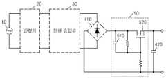
돌입 전류 차단부(50)는 상기 정류되는 동안 돌입 전류(inrush current)의 발생을 차단한다. 돌입 전류 차단부(50)는 돌입 전류 차단부(50)의 커패시터의 충전량에 따라 스위칭되는 돌입 전류 차단부(50)의 스위치에 의하여 돌입 전류를 차단한다. 여기서, 스위치는 FET(field effect transistor) 등과 같은 트랜지스터를 이용하여 구현될 수 있다. 돌입 전류 차단부(50)는 정류부(40)의 브릿지 정류기(410)의 후단과 LED 구동부(60)의 전단 사이에서 분리(discrete) 회로로 구비된다.The inrush current cut-off
앞서 설명한 바와 같이, 정류부(40)는 전해 커패시터와 같은 커패시터(420)를 구비할 수 있는데, 이 때 전해 커패시터의 초기 충전 전류에 의해 돌입 전류가 발생될 수 있다. 이와 같은 돌입 전류로 인하여 LED 조명 장치(1)는 안정기(20), LED 구동부(60) 및 광원부(70) 등에 데미지를 입히게 될 수 있다. 그러므로, 본 실시예에 따른 LED 조명 장치(1)는 돌입 전류 차단부(50)에 의해 돌입 전류에 의한 데미지를 방지할 수 있다.As described above, the rectifying
도 5는 본 발명의 일 실시예에 따른 돌입 전류 차단부(50)를 도시한 도면이다. 도 5를 참고하면, 돌입 전류 차단부(50)는 브릿지 정류기(410)의 후단과 LED 구동부(60)의 전단 사이에 구비된다.5 is a diagram illustrating a rush
앞서 설명한 바와 같이, 전해 커패시터와 같은 정류부(40)의 커패시터(420)의 초기 충전 전류에 의해 돌입 전류가 발생될 수 있다. 종래의 할로겐 램프 대비 LED 조명 장치(1)는 약 1/5이하의 전력을 소비하기 때문에, 많은 전류가 공급될 경우 LED 조명 장치(1)의 안정기(20) 등은 데미지를 입을 수 있다.As described above, an inrush current can be generated by the initial charge current of the
이와 같은 돌입 전류를 방지하기 위하여, 돌입 전류 차단부(50)는 커패시터(510)의 충전량에 따라 스위칭되는 스위치(520)에 의하여 돌입 전류를 차단한다.In order to prevent the inrush current, the inrush current cut-off
보다 상세하게 설명하면, 돌입 전류 차단부(50)는 정현파의 매 시작 주기에 기동될 때 커패시터(510)의 충전 시간 또는 충전량에 비례하여 스위치(520)를 서서히 도통시킴으로써, 기동시 정류부(40)의 커패시터(420)에 의해 발생되는 돌입 전류를 제한한다. 그리고, 돌입 전류 차단부(50)의 스위치(520)는 돌입 전류 없이 LED 조명 장치(1)가 안정적으로 구동될 경우에는 ON 상태로 되어 LED 조명 장치(1)의 회로의 손실(Ploss = Iin2 ×RDSon)이 최소화되도록 동작된다.More specifically, the inrush
이로써, 돌입 전류 차단부(50)는 LED 조명 장치(1)의 회로의 손실과 발열 없이 돌입 전류를 차단할 수 있다.Thereby, the inrush current cut-off
다시 도 1을 참고하면, LED 구동부(60)는 돌입 전류가 차단되어 공급된 직류 전원(도 4a의 404 또는 도 4b의 406)을 이용하여 LED의 동작을 제어한다.Referring again to FIG. 1, the
광원부(70)는 적어도 하나의 LED를 포함한다. 즉, LED가 LED 구동부(60)의 제어에 의해 구동되어 발광됨으로써, LED 조명 장치(1)는 조명 또는 램프로써의 기능을 수행한다.The
LED 구동부(60) 및 광원부(70)의 구체적 회로 구성 및 동작은 당해 기술분야에서 통상의 지식을 가진 자에게 자명하므로, 자세한 설명은 생략하도록 하겠다.The specific circuit configuration and operation of the
이와 같이, 본 실시예에 따른 LED 조명 장치(1)는 전압 승압부(30)에 의해 안정기(20)의 출력을 승압시킴으로써 안정기(20)의 사용에 따른 LED의 광량이 저하되는 현상을 방지할 수 있다. 또한, 본 실시예에 따른 LED 조명 장치(1)는 전압 승압부(30)에 의해 안정기(20)의 출력을 승압시킴으로써 정류부(40)의 커패시터(420)의 용량 또는 종류를 변경시킬 수 있어 LED 조명 장치(1)의 수명을 연장시키거나, 내부 회로의 공간을 확보할 수 있다. 나아가서, 본 실시예에 따른 LED 조명 장치(1)는 돌입 전류 차단부(50)에서 돌입 전류를 차단시킴으로써, 돌입 전류에 의한 안정기(20), LED 구동부(60), 광원부(70) 등의 회로의 데미지를 방지할 수 있다.As described above, the
즉, LED 조명 장치(1)는 전압 승압부(30) 또는 돌입 전류 차단부(50)를 구비함으로써 종래의 할로겐 램프, LED 램프의 회로 구성의 호환성 문제를 해결할 수 있다.That is, the
앞서 설명된 도 1의 LED 조명 장치(1)는 전압 승압부(30) 및 돌입 전류 차단부(50)를 모두 구비하도록 도시되었다. 하지만, LED 조명 장치(1)는 전압 승압부(30) 및 돌입 전류 차단부(50) 중 어느 하나의 회로만을 구비하여 동작될 수 있다.The
나아가서, 도 1의 전압 승압부(30) 및 돌입 전류 차단부(50) 중 적어도 하나는 LED 조명 장치(1) 뿐만 아니라, 광원부(70) 대신 다른 부하를 갖는 일반적인 회로 장치에도 구비되어 상기와 같이 동작될 수 있다.Furthermore, at least one of the
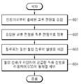
도 6은 본 발명의 일 실시예에 따른 LED 조명 장치(1)를 구동시키는 방법의 흐름도이다. 도 6을 참조하면, 본 실시예에 따른 LED 조명 장치(1)의 구동 방법은 도 1에 도시된 LED 조명 장치(1)에서 시계열적으로 처리되는 단계들로 구성된다. 따라서, 이하 생략된 내용이라 하더라도 도 1에 도시된 LED 조명 장치(1)에 관하여 이상에서 기술된 내용은 본 실시예에 따른 구동 방법에도 적용된다.6 is a flowchart of a method of driving the
601 단계에서 전원 승압부(30)는 안정기(20)로부터 출력된 교류 전원을 승압한다.In
602 단계에서 정류부(40)는 승압된 교류 전원을 직류 전원으로 정류한다.In
603 단계에서 돌입 전류 차단부(50)는 정류되는 동안 돌입 전류(inrush current)의 발생을 차단한다.In
604 단계에서 LED 구동부(60)는 돌입 전류가 차단되어 공급된 직류 전원을 이용하여 LED의 동작을 제어한다.In
이제까지 본 발명에 대하여 그 바람직한 실시예들을 중심으로 살펴보았다. 본 발명이 속하는 기술 분야에서 통상의 지식을 가진 자는 본 발명이 본 발명의 본질적인 특성에서 벗어나지 않는 범위에서 변형된 형태로 구현될 수 있음을 이해할 수 있을 것이다. 그러므로 개시된 실시예들은 한정적인 관점이 아니라 설명적인 관점에서 고려되어야 한다. 본 발명의 범위는 전술한 설명이 아니라 특허청구범위에 나타나 있으며, 그와 동등한 범위 내에 있는 모든 차이점은 본 발명에 포함된 것으로 해석되어야 할 것이다.The present invention has been described with reference to the preferred embodiments. It will be understood by those skilled in the art that various changes in form and details may be made therein without departing from the spirit and scope of the invention as defined by the appended claims. Therefore, the disclosed embodiments should be considered in an illustrative rather than a restrictive sense. The scope of the present invention is defined by the appended claims rather than by the foregoing description, and all differences within the scope of equivalents thereof should be construed as being included in the present invention.
1:LED 조명 장치10:전원 공급부
20:안정기30:전원 승압부
40:정류부410:브릿지 정류기
420:커패시터50:돌입 전류 차단부
60:LED 구동부70:광원부1: LED lighting device 10: power supply part
20: ballast 30: power supply step-
40: rectification part 410: bridge rectifier
420: capacitor 50: inrush current shutoff unit
60: LED driver 70: light source
Claims (16)
Translated fromKorean상기 LED 조명 장치의 구동을 안정시키기 위하여, 상기 공급된 상용 교류 전원을 소정 전압의 교류 전원으로 출력하는 안정기;
상기 안정기로부터 출력된 교류 전원을 승압하여 출력하는 전원 승압부;
상기 승압된 교류 전원을 직류 전원으로 정류하는 정류부;
상기 정류되는 동안 돌입 전류(inrush current)의 발생을 차단하는 돌입 전류 차단부; 및
상기 정류된 직류 전원을 이용하여 상기 LED의 동작을 제어하는 LED 구동부를 포함하고,
상기 정류부는 브릿지 정류기 및 커패시터를 포함하고,
상기 정류부에 포함된 상기 커패시터의 용량 및 상기 커패시터의 종류는, 상기 승압된 교류 전원에 기초하여, 결정되고,
상기 돌입 전류 차단부는 트랜지스터 및 상기 돌입 전류 차단부의 트랜지스터의 게이트에 연결되는 커패시터를 포함하고,
상기 돌입 전류 차단부의 트랜지스터는 상기 정류부의 커패시터와 연결되어 상기 정류부의 커패시터에 의해 발생되는 돌입 전류를 차단하고, 상기 돌입 전류 차단부의 트랜지스터는 상기 돌입 전류 차단부의 커패시터의 충전량에 따라 스위칭 되고,
상기 돌입 전류 차단부는 상기 브릿지 정류기 및 상기 정류부의 커패시터 사이에 연결되는 것을 특징으로 하는 장치.A light emitting diode (LED) lighting apparatus for driving an LED using a supplied commercial AC power source,
A stabilizer for outputting the supplied commercial AC power to an AC power source of a predetermined voltage in order to stabilize driving of the LED lighting apparatus;
A power supply step-up unit for stepping up the AC power outputted from the ballast and outputting the AC power;
A rectifying unit for rectifying the boosted AC power to a DC power;
An inrush current cutoff unit for blocking an occurrence of an inrush current during the rectification; And
And an LED driving unit for controlling operation of the LED using the rectified DC power,
Wherein the rectifying part includes a bridge rectifier and a capacitor,
The capacity of the capacitor included in the rectifying unit and the type of the capacitor are determined based on the boosted AC power supply,
Wherein the inrush current blocking portion includes a transistor and a capacitor connected to a gate of the transistor of the inrush current blocking portion,
The transistor of the inrush current cutoff portion is connected to the capacitor of the rectification portion to cut off the inrush current generated by the capacitor of the rectification portion and the transistor of the inrush current cutoff portion is switched in accordance with the charged amount of the capacitor of the inrush current cutoff portion,
And the inrush current blocking unit is connected between the bridge rectifier and the capacitor of the rectifying unit.
상기 전원 승압부는
상기 안정기와 접지되어 연결된 인덕터 및 커패시터에 의한 공진 현상을 이용하여 승압하는 장치.8. The method of claim 7,
The power-
And a resonance phenomenon caused by an inductor and a capacitor which are grounded and connected to the ballast.
상기 안정기를 통해 공급된 교류 전원을 직류 전원으로 정류하는 정류부;
상기 정류되는 동안 돌입 전류(inrush current)의 발생을 차단하는 돌입 전류 차단부; 및
상기 돌입 전류가 차단되어 공급된 직류 전원을 이용하여 상기 LED의 동작을 제어하는 LED 구동부를 포함하고,
상기 정류부는 브릿지 정류기 및 커패시터를 포함하고,
상기 정류부에 포함된 상기 커패시터의 용량 및 상기 커패시터의 종류는, 상기 정류부로 공급된 교류 전원에 기초하여 결정되고,
상기 돌입 전류 차단부는 트랜지스터 및 상기 돌입 전류 차단부의 트랜지스터의 게이트에 연결되는 커패시터를 포함하고,
상기 돌입 전류 차단부의 트랜지스터는 상기 정류부의 커패시터와 연결되어 상기 정류부의 커패시터에 의해 발생되는 돌입 전류를 차단하고, 상기 돌입 전류 차단부의 트랜지스터는 상기 돌입 전류 차단부의 커패시터의 충전량에 따라 스위칭 되고,
상기 돌입 전류 차단부는 상기 브릿지 정류기 및 상기 정류부의 커패시터 사이에 연결되는 것을 특징으로 하는 장치.1. A light emitting diode (LED) lighting apparatus for driving an LED by supplying commercial AC power through a ballast,
A rectifier for rectifying the AC power supplied through the ballast to DC power;
An inrush current cutoff unit for blocking an occurrence of an inrush current during the rectification; And
And an LED driving unit for controlling the operation of the LED by using the supplied direct current power with the inrush current interrupted,
Wherein the rectifying part includes a bridge rectifier and a capacitor,
The capacity of the capacitor included in the rectifying unit and the type of the capacitor are determined based on the alternating current power supplied to the rectifying unit,
Wherein the inrush current blocking portion includes a transistor and a capacitor connected to a gate of the transistor of the inrush current blocking portion,
The transistor of the inrush current cutoff portion is connected to the capacitor of the rectification portion to cut off the inrush current generated by the capacitor of the rectification portion and the transistor of the inrush current cutoff portion is switched in accordance with the charged amount of the capacitor of the inrush current cutoff portion,
And the inrush current blocking unit is connected between the bridge rectifier and the capacitor of the rectifying unit.
상기 돌입 전류 차단부는
상기 정류부의 브릿지 정류기의 후단과 상기 LED 구동부의 전단 사이에서 분리(discrete) 회로로 구비되는 장치.10. The method of claim 9,
The inrush current cut-
And a discrete circuit between the rear end of the rectifier of the rectifying part and the front end of the LED driving part.
상기 안정기로부터 출력된 상기 소정 전압의 교류 전원을 승압하는 전원 승압부;
상기 승압된 교류 전원을 직류 전원으로 정류하는 정류부;
상기 정류되는 동안 돌입 전류(inrush current)의 발생을 차단하는 돌입 전류 차단부; 및
상기 돌입 전류가 차단되어 공급된 직류 전원을 이용하여 상기 회로 장치의 구동을 제어하는 구동부를 포함하고,
상기 정류부는 브릿지 정류기 및 커패시터를 포함하고,
상기 정류부에 포함된 상기 커패시터의 용량 및 상기 커패시터의 종류는, 상기 승압된 교류 전원에 기초하여 결정되고,
상기 돌입 전류 차단부는 트랜지스터 및 상기 돌입 전류 차단부의 트랜지스터의 게이트에 연결되는 커패시터를 포함하고,
상기 돌입 전류 차단부의 트랜지스터는 상기 정류부의 커패시터와 연결되어 상기 정류부의 커패시터에 의해 발생되는 돌입 전류를 차단하고, 상기 돌입 전류 차단부의 트랜지스터는 상기 돌입 전류 차단부의 커패시터의 충전량에 따라 스위칭 되고,
상기 돌입 전류 차단부는 상기 브릿지 정류기 및 상기 정류부의 커패시터 사이에 연결되는 것을 특징으로 하는 회로 장치.A stabilizer for outputting the supplied commercial AC power to an AC power supply of a predetermined voltage for stabilizing the driving of the circuit device;
A power supply voltage step-up unit for stepping up the AC power of the predetermined voltage outputted from the ballast;
A rectifying unit for rectifying the boosted AC power to a DC power;
An inrush current cutoff unit for blocking an occurrence of an inrush current during the rectification; And
And a driving unit for controlling driving of the circuit device by using the supplied DC power with the inrush current interrupted,
Wherein the rectifying part includes a bridge rectifier and a capacitor,
The capacity of the capacitor included in the rectifying unit and the type of the capacitor are determined based on the boosted AC power supply,
Wherein the inrush current blocking portion includes a transistor and a capacitor connected to a gate of the transistor of the inrush current blocking portion,
The transistor of the inrush current cutoff portion is connected to the capacitor of the rectification portion to cut off the inrush current generated by the capacitor of the rectification portion and the transistor of the inrush current cutoff portion is switched in accordance with the charged amount of the capacitor of the inrush current cutoff portion,
And the inrush current breaking portion is connected between the bridge rectifier and the capacitor of the rectifying portion.
상기 돌입 전류 차단부는
상기 정류부의 브릿지 정류기의 후단과 상기 LED 구동부의 전단 사이에서 분리 회로로 구비되는 장치.8. The method of claim 7,
The inrush current cut-
And a separation circuit between the rear end of the rectifier of the rectifying unit and the front end of the LED driving unit.
Priority Applications (4)
| Application Number | Priority Date | Filing Date | Title |
|---|---|---|---|
| KR1020110095817AKR101942028B1 (en) | 2011-09-22 | 2011-09-22 | LED lighting apparatus |
| DE102012108669.9ADE102012108669B4 (en) | 2011-09-22 | 2012-09-17 | LED lighting device and method for driving a light-emitting diode |
| CN201210350855.8ACN103024982B (en) | 2011-09-22 | 2012-09-19 | Light emitting diode lighting equipment |
| US13/625,446US9107256B2 (en) | 2011-09-22 | 2012-09-24 | Light emitting diode lighting apparatus |
Applications Claiming Priority (1)
| Application Number | Priority Date | Filing Date | Title |
|---|---|---|---|
| KR1020110095817AKR101942028B1 (en) | 2011-09-22 | 2011-09-22 | LED lighting apparatus |
Publications (2)
| Publication Number | Publication Date |
|---|---|
| KR20130032108A KR20130032108A (en) | 2013-04-01 |
| KR101942028B1true KR101942028B1 (en) | 2019-01-25 |
Family
ID=47828043
Family Applications (1)
| Application Number | Title | Priority Date | Filing Date |
|---|---|---|---|
| KR1020110095817AActiveKR101942028B1 (en) | 2011-09-22 | 2011-09-22 | LED lighting apparatus |
Country Status (4)
| Country | Link |
|---|---|
| US (1) | US9107256B2 (en) |
| KR (1) | KR101942028B1 (en) |
| CN (1) | CN103024982B (en) |
| DE (1) | DE102012108669B4 (en) |
Cited By (1)
| Publication number | Priority date | Publication date | Assignee | Title |
|---|---|---|---|---|
| KR102525520B1 (en) | 2023-01-26 | 2023-04-25 | 엘이디라이팅 주식회사 | Blinking-free and flicker-free ac direct-coupled type lighting device including boost converter |
Families Citing this family (12)
| Publication number | Priority date | Publication date | Assignee | Title |
|---|---|---|---|---|
| US11131431B2 (en) | 2014-09-28 | 2021-09-28 | Jiaxing Super Lighting Electric Appliance Co., Ltd | LED tube lamp |
| EP3039946B1 (en)* | 2013-08-27 | 2017-05-31 | Philips Lighting Holding B.V. | Led retrofit lamp having active over-current protection circuit |
| US11480305B2 (en) | 2014-09-25 | 2022-10-25 | Jiaxing Super Lighting Electric Appliance Co., Ltd. | LED tube lamp |
| CN112197181A (en) | 2014-09-28 | 2021-01-08 | 嘉兴山蒲照明电器有限公司 | LED straight lamp |
| US10560989B2 (en) | 2014-09-28 | 2020-02-11 | Jiaxing Super Lighting Electric Appliance Co., Ltd | LED tube lamp |
| US11519565B2 (en) | 2015-03-10 | 2022-12-06 | Jiaxing Super Lighting Electric Appliance Co., Ltd | LED lamp and its power source module |
| US9897265B2 (en) | 2015-03-10 | 2018-02-20 | Jiaxing Super Lighting Electric Appliance Co., Ltd. | LED tube lamp having LED light strip |
| US20210219400A1 (en)* | 2016-03-31 | 2021-07-15 | Philips Lighting Holding B.V. | Conversion circuit between fluorescent ballast and led |
| CN107204656B (en)* | 2017-05-11 | 2020-03-27 | 唐智科技湖南发展有限公司 | Rapid, efficient and boosting charging method based on generalized resonance |
| US11617316B2 (en)* | 2017-11-10 | 2023-04-04 | James S. Ray | Apparatus and methods for a hydroponics system with enhanced heat transfer |
| US12349638B2 (en) | 2017-11-10 | 2025-07-08 | James S. RAY, JR. | Apparatus and methods for a hydroponics system with light control |
| CN219453696U (en) | 2021-01-27 | 2023-08-01 | 嘉兴山蒲照明电器有限公司 | LED straight tube lamp and lighting system |
Citations (3)
| Publication number | Priority date | Publication date | Assignee | Title |
|---|---|---|---|---|
| JP2002369501A (en)* | 2001-06-05 | 2002-12-20 | Sharp Corp | Stabilized power supply |
| JP2009283839A (en)* | 2008-05-26 | 2009-12-03 | Panasonic Electric Works Co Ltd | Light emitting diode driving device and illuminator |
| US20100289418A1 (en)* | 2009-05-14 | 2010-11-18 | Altair Engineering, Inc. | Electronic circuit for dc conversion of fluorescent lighting ballast |
Family Cites Families (16)
| Publication number | Priority date | Publication date | Assignee | Title |
|---|---|---|---|---|
| JPS62225180A (en)* | 1986-03-26 | 1987-10-03 | Murata Mfg Co Ltd | High voltage power source for discharge tube |
| FR2687514A1 (en)* | 1992-02-14 | 1993-08-20 | Cableco Sa | VARIATOR DEVICE FOR THE INTENSITY OF ELECTRICAL CURRENT IN A RECEIVER. |
| JP3473789B2 (en) | 1994-12-29 | 2003-12-08 | ソニー株式会社 | Booster device and electronic equipment |
| KR0171987B1 (en) | 1995-12-22 | 1999-03-30 | 김주용 | Gate electrode formation method of semiconductor device |
| DE19714980C2 (en)* | 1997-04-10 | 2001-01-04 | Asm Automation Sensorik Messte | Ultrasonic position sensor with a pulse generator for generating short voltage pulses |
| US6181084B1 (en)* | 1998-09-14 | 2001-01-30 | Eg&G, Inc. | Ballast circuit for high intensity discharge lamps |
| KR100360673B1 (en) | 2000-02-21 | 2002-11-14 | 오규창 | Flickering Apparatus Of Light Emitting Diode For Traffic saft Using Solar Battery And Low Voltage Storage Battery |
| US6359392B1 (en) | 2001-01-04 | 2002-03-19 | Motorola, Inc. | High efficiency LED driver |
| KR20030023372A (en)* | 2001-09-13 | 2003-03-19 | 최승희 | Power supply circuit of electronic ballast |
| JP4379416B2 (en) | 2005-04-26 | 2009-12-09 | エプソンイメージングデバイス株式会社 | LED drive circuit, illumination device, and electro-optical device |
| CN101222805B (en) | 2007-12-20 | 2012-07-18 | 北京中星微电子有限公司 | Method for multi-string LED time-sharing regulation and driving mechanism using the same |
| KR20100000588A (en) | 2008-06-25 | 2010-01-06 | 주식회사 반디라이트 | Reverse voltage and inrush current protection circuit of LED lighting module |
| KR101483627B1 (en) | 2008-07-29 | 2015-01-19 | 삼성디스플레이 주식회사 | Display device |
| DE102010001048A1 (en) | 2009-12-18 | 2011-06-22 | Tridonic Gmbh & Co Kg | Method for operating an electrical light source and operating circuit |
| JP2011171557A (en) | 2010-02-19 | 2011-09-01 | Toshiba Corp | Light emitting device, method of manufacturing the same, and light emitting device manufacturing apparatus |
| CN201774702U (en)* | 2010-08-16 | 2011-03-23 | 上海新华电子设备有限公司 | Constant-voltage driving power source for LED illumination |
- 2011
- 2011-09-22KRKR1020110095817Apatent/KR101942028B1/enactiveActive
- 2012
- 2012-09-17DEDE102012108669.9Apatent/DE102012108669B4/enactiveActive
- 2012-09-19CNCN201210350855.8Apatent/CN103024982B/enactiveActive
- 2012-09-24USUS13/625,446patent/US9107256B2/enactiveActive
Patent Citations (3)
| Publication number | Priority date | Publication date | Assignee | Title |
|---|---|---|---|---|
| JP2002369501A (en)* | 2001-06-05 | 2002-12-20 | Sharp Corp | Stabilized power supply |
| JP2009283839A (en)* | 2008-05-26 | 2009-12-03 | Panasonic Electric Works Co Ltd | Light emitting diode driving device and illuminator |
| US20100289418A1 (en)* | 2009-05-14 | 2010-11-18 | Altair Engineering, Inc. | Electronic circuit for dc conversion of fluorescent lighting ballast |
Cited By (1)
| Publication number | Priority date | Publication date | Assignee | Title |
|---|---|---|---|---|
| KR102525520B1 (en) | 2023-01-26 | 2023-04-25 | 엘이디라이팅 주식회사 | Blinking-free and flicker-free ac direct-coupled type lighting device including boost converter |
Also Published As
| Publication number | Publication date |
|---|---|
| CN103024982B (en) | 2016-06-22 |
| CN103024982A (en) | 2013-04-03 |
| US20130076255A1 (en) | 2013-03-28 |
| KR20130032108A (en) | 2013-04-01 |
| DE102012108669B4 (en) | 2024-01-18 |
| US9107256B2 (en) | 2015-08-11 |
| DE102012108669A1 (en) | 2013-03-28 |
Similar Documents
| Publication | Publication Date | Title |
|---|---|---|
| KR101942028B1 (en) | LED lighting apparatus | |
| CA2841460C (en) | High voltage led and driver | |
| US8872426B2 (en) | Arrangements and methods for triac dimming of gas discharge lamps powered by electronic ballasts | |
| CN204836661U (en) | Led lamp | |
| CN102164440B (en) | Lighting device and illumination fixture using thereof | |
| CA2949736A1 (en) | Improvements relating to power adaptors | |
| CN102386788A (en) | DC power source unit and LED lamp system | |
| KR101680342B1 (en) | LED lamp driver apparatus with frequency tracking function | |
| KR20110062243A (en) | LED lighting device using fluorescent ballast | |
| JP5355600B2 (en) | Fluorescent lamp circuit using light emitting elements | |
| CN111212497A (en) | Driving circuit | |
| KR101844460B1 (en) | LED lamp control circuit compatible type fluorescent and lighting the use | |
| KR101598415B1 (en) | LED lamp driver circuit | |
| KR20140049841A (en) | Apparatus and method for supplying power of led lighting, and led lighting apparatus using that | |
| CN108430129B (en) | LED lamp for placing in a fluorescent lamp fixture | |
| CN108934101B (en) | LED lamp | |
| CN111212499B (en) | Rectifier circuit for LED lamp driver | |
| KR101777566B1 (en) | LED Lamp | |
| KR20160125805A (en) | LED Drive using dual current controller compatible for fluorescent ballast | |
| US20160073459A1 (en) | Led lamp device | |
| KR20160073555A (en) | LED Lightening Circuit Compatible with Magnetic and Electronic Flourescent Lamp Ballast | |
| KR100625262B1 (en) | Electronic Ballast for High Voltage Discharge Fluorescent Lamp with Improved Resonance Output Circuit | |
| CN104768314B (en) | Electronic stabilizer for fluorescent lamp | |
| JP2016115588A (en) | Power supply circuit | |
| CN102026458A (en) | Driving device of planar light source |
Legal Events
| Date | Code | Title | Description |
|---|---|---|---|
| PA0109 | Patent application | Patent event code:PA01091R01D Comment text:Patent Application Patent event date:20110922 | |
| N231 | Notification of change of applicant | ||
| PN2301 | Change of applicant | Patent event date:20120808 Comment text:Notification of Change of Applicant Patent event code:PN23011R01D | |
| PG1501 | Laying open of application | ||
| A201 | Request for examination | ||
| PA0201 | Request for examination | Patent event code:PA02012R01D Patent event date:20160818 Comment text:Request for Examination of Application Patent event code:PA02011R01I Patent event date:20110922 Comment text:Patent Application | |
| E902 | Notification of reason for refusal | ||
| PE0902 | Notice of grounds for rejection | Comment text:Notification of reason for refusal Patent event date:20170828 Patent event code:PE09021S01D | |
| E902 | Notification of reason for refusal | ||
| PE0902 | Notice of grounds for rejection | Comment text:Notification of reason for refusal Patent event date:20180322 Patent event code:PE09021S01D | |
| E902 | Notification of reason for refusal | ||
| PE0902 | Notice of grounds for rejection | Comment text:Notification of reason for refusal Patent event date:20180907 Patent event code:PE09021S01D | |
| E701 | Decision to grant or registration of patent right | ||
| PE0701 | Decision of registration | Patent event code:PE07011S01D Comment text:Decision to Grant Registration Patent event date:20190110 | |
| PR0701 | Registration of establishment | Comment text:Registration of Establishment Patent event date:20190118 Patent event code:PR07011E01D | |
| PR1002 | Payment of registration fee | Payment date:20190121 End annual number:3 Start annual number:1 | |
| PG1601 | Publication of registration | ||
| PR1001 | Payment of annual fee | Payment date:20211229 Start annual number:4 End annual number:4 | |
| PR1001 | Payment of annual fee | Payment date:20221221 Start annual number:5 End annual number:5 | |
| PR1001 | Payment of annual fee | Payment date:20231226 Start annual number:6 End annual number:6 | |
| PR1001 | Payment of annual fee | Payment date:20241226 Start annual number:7 End annual number:7 |