KR101938111B1 - Control panel device of central control system for industrial plants - Google Patents
Control panel device of central control system for industrial plantsDownload PDFInfo
- Publication number
- KR101938111B1 KR101938111B1KR1020180074102AKR20180074102AKR101938111B1KR 101938111 B1KR101938111 B1KR 101938111B1KR 1020180074102 AKR1020180074102 AKR 1020180074102AKR 20180074102 AKR20180074102 AKR 20180074102AKR 101938111 B1KR101938111 B1KR 101938111B1
- Authority
- KR
- South Korea
- Prior art keywords
- control
- control panel
- casing
- door
- general
- Prior art date
- Legal status (The legal status is an assumption and is not a legal conclusion. Google has not performed a legal analysis and makes no representation as to the accuracy of the status listed.)
- Active
Links
- 230000000007visual effectEffects0.000claimsabstractdescription21
- 238000004891communicationMethods0.000claimsdescription8
- 238000000034methodMethods0.000claimsdescription4
- 238000013461designMethods0.000claimsdescription3
- 238000009423ventilationMethods0.000description5
- 239000002184metalSubstances0.000description2
- 238000001816coolingMethods0.000description1
- 230000005611electricityEffects0.000description1
- 238000012986modificationMethods0.000description1
- 230000004048modificationEffects0.000description1
- 238000012544monitoring processMethods0.000description1
- 238000013021overheatingMethods0.000description1
- 238000012545processingMethods0.000description1
- 238000004092self-diagnosisMethods0.000description1
- 239000000126substanceSubstances0.000description1
Images


Classifications
- G—PHYSICS
- G05—CONTROLLING; REGULATING
- G05B—CONTROL OR REGULATING SYSTEMS IN GENERAL; FUNCTIONAL ELEMENTS OF SUCH SYSTEMS; MONITORING OR TESTING ARRANGEMENTS FOR SUCH SYSTEMS OR ELEMENTS
- G05B19/00—Programme-control systems
- G05B19/02—Programme-control systems electric
- G05B19/418—Total factory control, i.e. centrally controlling a plurality of machines, e.g. direct or distributed numerical control [DNC], flexible manufacturing systems [FMS], integrated manufacturing systems [IMS] or computer integrated manufacturing [CIM]
- G—PHYSICS
- G05—CONTROLLING; REGULATING
- G05B—CONTROL OR REGULATING SYSTEMS IN GENERAL; FUNCTIONAL ELEMENTS OF SUCH SYSTEMS; MONITORING OR TESTING ARRANGEMENTS FOR SUCH SYSTEMS OR ELEMENTS
- G05B19/00—Programme-control systems
- G05B19/02—Programme-control systems electric
- G05B19/18—Numerical control [NC], i.e. automatically operating machines, in particular machine tools, e.g. in a manufacturing environment, so as to execute positioning, movement or co-ordinated operations by means of programme data in numerical form
- G05B19/409—Numerical control [NC], i.e. automatically operating machines, in particular machine tools, e.g. in a manufacturing environment, so as to execute positioning, movement or co-ordinated operations by means of programme data in numerical form characterised by using manual data input [MDI] or by using control panel, e.g. controlling functions with the panel; characterised by control panel details or by setting parameters
- G—PHYSICS
- G05—CONTROLLING; REGULATING
- G05B—CONTROL OR REGULATING SYSTEMS IN GENERAL; FUNCTIONAL ELEMENTS OF SUCH SYSTEMS; MONITORING OR TESTING ARRANGEMENTS FOR SUCH SYSTEMS OR ELEMENTS
- G05B23/00—Testing or monitoring of control systems or parts thereof
- G05B23/02—Electric testing or monitoring
- G05B23/0205—Electric testing or monitoring by means of a monitoring system capable of detecting and responding to faults
- G05B23/0208—Electric testing or monitoring by means of a monitoring system capable of detecting and responding to faults characterized by the configuration of the monitoring system
- G05B23/0213—Modular or universal configuration of the monitoring system, e.g. monitoring system having modules that may be combined to build monitoring program; monitoring system that can be applied to legacy systems; adaptable monitoring system; using different communication protocols
- G—PHYSICS
- G05—CONTROLLING; REGULATING
- G05B—CONTROL OR REGULATING SYSTEMS IN GENERAL; FUNCTIONAL ELEMENTS OF SUCH SYSTEMS; MONITORING OR TESTING ARRANGEMENTS FOR SUCH SYSTEMS OR ELEMENTS
- G05B2219/00—Program-control systems
- G05B2219/20—Pc systems
- G05B2219/23—Pc programming
- G05B2219/23377—Touch screen, with representation of buttons, machine on screen
- G—PHYSICS
- G05—CONTROLLING; REGULATING
- G05B—CONTROL OR REGULATING SYSTEMS IN GENERAL; FUNCTIONAL ELEMENTS OF SUCH SYSTEMS; MONITORING OR TESTING ARRANGEMENTS FOR SUCH SYSTEMS OR ELEMENTS
- G05B2219/00—Program-control systems
- G05B2219/20—Pc systems
- G05B2219/24—Pc safety
- G05B2219/24097—Camera monitors controlled machine
- Y—GENERAL TAGGING OF NEW TECHNOLOGICAL DEVELOPMENTS; GENERAL TAGGING OF CROSS-SECTIONAL TECHNOLOGIES SPANNING OVER SEVERAL SECTIONS OF THE IPC; TECHNICAL SUBJECTS COVERED BY FORMER USPC CROSS-REFERENCE ART COLLECTIONS [XRACs] AND DIGESTS
- Y02—TECHNOLOGIES OR APPLICATIONS FOR MITIGATION OR ADAPTATION AGAINST CLIMATE CHANGE
- Y02P—CLIMATE CHANGE MITIGATION TECHNOLOGIES IN THE PRODUCTION OR PROCESSING OF GOODS
- Y02P90/00—Enabling technologies with a potential contribution to greenhouse gas [GHG] emissions mitigation
- Y02P90/02—Total factory control, e.g. smart factories, flexible manufacturing systems [FMS] or integrated manufacturing systems [IMS]
Landscapes
- Engineering & Computer Science (AREA)
- Physics & Mathematics (AREA)
- General Physics & Mathematics (AREA)
- Automation & Control Theory (AREA)
- Manufacturing & Machinery (AREA)
- General Engineering & Computer Science (AREA)
- Quality & Reliability (AREA)
- Human Computer Interaction (AREA)
- Testing And Monitoring For Control Systems (AREA)
Abstract
Description
Translated fromKorean본 발명은 제어반에 관한 것으로서, 보다 상세하게는, 각종 산업플랜트의 중앙제어실에 설치되어 사용되는 중앙제어시스템을 구성하며 상호 유기적으로 연결된 산업플랜트용 중앙제어시스템의 제어반장치에 관한 것이다.BACKGROUND OF THE INVENTION 1. Field of the Invention The present invention relates to a control panel, and more particularly, to a control panel device of a central control system for an industrial plant, which constitutes a central control system installed in and used in a central control room of various industrial plants.
각종 산업시설, 가령 발전소나 정유공장 또는 화학공장 등과 같은 산업용 플랜트의 경우, 공장 전체의 상황을 통일적으로 제어하며, 원거리에서 작동하는 현장장비나 계측기기, 밸브 등을 통합 제어하기 위한 중앙제어시스템이 설치 및 운용된다.For industrial plants such as power stations, refineries or chemical plants, a centralized control system for unified control of the entire factory and integrated control of field equipment, measuring instruments and valves operating at a distance Installed and operated.
중앙제어시스템에 포함되는 제어반은, 개별 시스템을 전반적으로 총괄하며, 설비를 구성하는 현장기기들을 제어하고, 작동 정보를 수집 및 분석하여 적절히 대응하는 역할을 하며, 경우에 따라 현장기기들을 독자적으로 제어할 수 있도록 독립적 운영도 가능하다.The control panel included in the central control system collectively manages the individual systems, controls the on-site apparatuses constituting the apparatus, collects and analyzes operational information and appropriately responds thereto, and in some cases, controls the on- Independent operation is possible.
그런데, 산업플랜트용 제어처리 시스템은, 매우 복잡하고 제어하기 위한 대상이 많으므로, 중앙제어시스템에는 많은 수의 제어반이 상호 연결되어 구성된다. 상기 제어반은, 말하자면, 중앙제어실을 가득 채우고 있으며, 관리자는 각 제어반을 체크하고 점검하기 위하여, 개별 제어반을 방문하여 도어를 일일이 열고 내부 상태를 체크하고 도어를 다시 잠그는 일을 반복하여야 한다. 이러한 과정은 매우 번거롭고 짧지 않은 작업시간을 요구한다.However, since a control processing system for an industrial plant is very complicated and has many objects to be controlled, a large number of control panels are connected to each other in the central control system. The control panel, which is to say the central control room is full, and the manager has to visit the individual control panel, open the door individually, check the internal state and re-lock the door, in order to check and check each control panel. This process requires a very cumbersome and short working time.
본 발명은 상기 문제점을 해소하고자 창출한 것으로서, 상호 연결되어 있는 다수의 제어반 중 임의의 제어반을 통해 나머지 제어반의 상태를 통합적으로 파악할 수 있어 관리 및 운용이 매우 편리한 산업플랜트용 중앙제어시스템의 제어반장치를 제공함에 목적이 있다.The present invention has been made in order to solve the above problems, and it is an object of the present invention to provide a control panel device for a central control system for industrial plants, which can collectively grasp the states of the remaining control panels through arbitrary control panels among a plurality of control panels connected to each other, And the like.
상기 목적을 달성하기 위한 본 발명의 산업플랜트용 중앙제어시스템의 제어반장치는, 내부공간을 가지며 전방으로 개방된 케이싱, 상기 케이싱의 내부에 배치되고 제어신호를 출력하는 다종 다수의 제어부품, 상기 케이싱의 내부를 촬영하는 촬영부를 포함하는 다수의 일반제어반과; 상기 다수의 일반제어반과 접속되는 것으로서, 내부공간을 가지며 전방으로 개방된 케이싱, 상기 케이싱내에 배치되고 제어신호를 출력하는 다종 다수의 제어부품, 상기 케이싱에 회동 가능하도록 장착되며 케이싱을 개폐하는 도어, 상기 도어의 내측에 장착되며 케이싱 내부를 촬영하는 촬영부, 상기 다수의 일반제어반의 촬영부로부터 촬영내용을 전달받아 출력하되 선택된 일반제어반의 촬영내용을 출력하는 비주얼제어플레이트를 갖는 관리제어반이 구비된다.In order to achieve the above object, a control panel apparatus of a central control system for an industrial plant according to the present invention comprises: a casing having an inner space and opened frontward; a plurality of control components disposed inside the casing and outputting control signals; A plurality of general control panels including a photographing section for photographing the interior of the vehicle; A plurality of control parts arranged in the casing and outputting control signals, a door rotatably mounted on the casing and opening and closing the casing, a plurality of control parts connected to the plurality of general control boards, And a visual control plate mounted on the inside of the door for photographing the inside of the casing and a visual control plate for receiving and outputting the photographed contents from the photographing units of the general control panels and outputting photographed contents of the selected general control panel .
또한, 상기 비주얼제어플레이트는; 상기 도어의 일측단부에 힌지 연결되며 사각틀의 형태를 취하고, 도어에 대해 겹쳐지거나 도어로부터 펼쳐지는 회동프레임과, 상기 회동프레임의, 도어를 향하는 후면에 고정되는 제어컴퓨터와, 상기 제어컴퓨터와 접속되며 상기 일반제어반과 접속하는 통신부와, 상기 회동프레임의 전면에 설치되며, 상기 통신부를 통해 전달받은 일반제어반 내부를 촬영한 영상을 디스플레이하는 터치패널을 포함한다.The visual control plate may further include: A control computer which is hinged to one end of the door and takes the form of a square frame and overlaps with or opens from the door; a control computer fixed to the rear surface of the rotation frame facing the door; And a touch panel disposed on a front surface of the rotating frame for displaying an image of the inside of a general control panel received through the communication unit.
아울러, 상기 도어에는; 도어에 대해 비주얼 제어플레이트를 겹쳤을 때, 상기 컴퓨터 및 통신부를 수용하는 수용하우징이 형성되고, 상기 수용하우징의 후면에는, 일반제어반과 관리제어반의 연결상태를 출력하는 현황출력부가 구비된다.Further, in the door, A reception housing for receiving the computer and the communication unit is formed when the visual control plate is overlapped with the door, and a status output unit for outputting the connection status of the general control board and the management control board is provided on the rear surface of the receiving housing.
또한, 상기 일반제어반 및 관리제어반의 케이싱에는, 제어반을 구별하는 식별표시부가 마킹되어 있으며, 상기 터치패널에는, 상기 식별표시부와 동일한 디자인의 아이콘이 배치되고, 터치패널은 임의의 아이콘을 터치했을 때, 해당 식별표시부를 갖는 일반제어반의 촬영 내용을 디스플레이한다.An identification display section for identifying the control panel is marked on the casing of the general control panel and the management control panel. An icon of the same design as that of the identification display section is arranged on the touch panel. When the touch panel touches an arbitrary icon , And displays the photographed contents of the general control panel having the corresponding identification display section.
상기와 같이 이루어지는 본 발명의 산업플랜트용 중앙제어시스템의 제어반장치장치는, 상호 연결되어 있는 다수의 제어반 중 임의의 제어반을 통해 나머지 제어반의 상태를 통합적으로 파악할 수 있어 관리 및 운용이 매우 편리하다.The control panel device of the central control system for industrial plants according to the present invention can be integrated in the control panel device through the control panel among the plurality of control panels connected to each other.
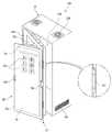
도 1은 본 발명의 일 실시예에 따른 산업플랜트용 중앙제어시스템의 제어반장치를 도시한 정면도이다.
도 2는 도 1에 도시한 제어반장치에서 관리제어반을 별도로 도시한 사시도이다.
도 3은 도 2의 관리제어반에서의 도어를 따로 도시한 사시도이다.
도 4는 도 2의 관리제어반에서의 비주얼제어플레이트를 별도로 도시한 사시도이다.
도 5는 도 2에 도시한 관리제어반의 도어와 비주얼제어플레이트를 펼친 모습을 도시한 도면이다.1 is a front view showing a control panel device of a central control system for an industrial plant according to an embodiment of the present invention.
FIG. 2 is a perspective view of the control panel device shown in FIG. 1, showing the management control panel separately.
3 is a perspective view of the door in the management control panel of FIG. 2; FIG.
4 is a perspective view showing the visual control plate in the management control panel of FIG. 2 separately.
5 is a view showing the door of the management control panel and the visual control plate of FIG. 2 opened.
이하, 본 발명에 따른 하나의 실시예를 첨부된 도면을 참조하여 보다 상세히 설명하기로 한다.Hereinafter, one embodiment according to the present invention will be described in detail with reference to the accompanying drawings.
기본적으로, 본 실시예에 따른 제어반장치(10)는, 각종 산업 플랜트를 제어하기 위한 중앙제어시스템의 일부로서, 중앙제어실에 배치되며 상호 접속된 상태로 적절한 제어신호를 출력한다. 특히 제어반장치(10)는, 다수의 일반제어반(10a)과 관리제어반(10b)으로 구성된다. 일반제어반(10a)은 일반적인 제어반의 역할을 하고, 관리제어반(10b)은 일반제어반의 역할에 더하여 후술할 관리제어도 수행한다.Basically, the
이러한 제어반장치(10)는, 내부공간을 가지며 전방으로 개방된 케이싱, 상기 케이싱의 내부에 배치되고 제어신호를 출력하는 다종 다수의 제어부품, 상기 케이싱의 내부를 촬영하는 촬영부를 포함하는 다수의 일반제어반과; 상기 다수의 일반제어반과 접속되는 것으로서, 내부공간을 가지며 전방으로 개방된 케이싱, 상기 케이싱내에 배치되고 제어신호를 출력하는 다종 다수의 제어부품, 상기 케이싱에 회동 가능하도록 장착되며 케이싱을 개폐하는 도어, 상기 도어의 내측에 장착되며 케이싱 내부를 촬영하는 촬영부, 상기 다수의 일반제어반의 촬영부로부터 촬영내용을 전달받아 출력하되 선택된 일반제어반의 촬영내용을 출력하는 비주얼제어플레이트를 갖는 관리제어반으로 구성된다.The
도 1은 본 발명의 일 실시예에 따른 산업플랜트용 중앙제어시스템의 제어반장치의 전체적인 모습을 도시한 정면도이다.1 is a front view showing an overall view of a control panel device of a central control system for an industrial plant according to an embodiment of the present invention.
도시한 바와 같이, 본 실시예에 따른 제어반장치(10)는, 상호 연접하는 다수의 일반제어반(10a)과, 하나의 관리제어반(10b)을 포함하여 구성된다. 위에 언급한 바와 같이, 일반제어반(10a)은 제어대상에 대한 일반적인 제어신호를 출력하는 것이고, 관리제어반(10b)은 일반적인 제어신호를 출력함은 물론 일반제어반(10a)을 제어하고 일반제어반의 제어현황을 출력하는 역할을 한다.As shown, the
상기 일반제어반(10a)은, 유기적으로 연결되며, 전체적인 플랜트에서의 서로 다른 부분을 제어한다. 당연히 일반제어반(10a) 내부의 제어부품(12)의 구성은 상이하다.The
일반제어반(10a)은, 내부공간을 가지며 전방으로 개방된 케이싱(13), 케이싱의 내부에 배치되고 제어신호를 출력하는 다종 다수의 제어부품(12), 케이싱(13)의 내부를 촬영하는 촬영부(14)를 포함한다. 일반제어반(10a)은 종류에 따라 케이싱(13)의 전방에 도어(15)를 가질 수도 있다. 도어(15)는 제어부품(12)을 보호한다.The
상기 촬영부(14)는 케이싱(13)의 내부를 통째로 촬영하는 카메라이다. 가령, 케이싱(13) 내부의 제어부품, 이를테면, 스위치나 차단기 또는 램프 등의 상태를 촬영하는 것으로서 촬영된 내용은 관리제어반(10b)으로 보낸다. 촬영부(14)가 촬영한 내용은 정영상 또는 동영상 일 수 있다.The photographing
아울러 촬영부(14)의 위치는 도어(15)의 내측이거나, 도어가 없을 경우에는 케이싱(13)의 적절한 위치, 즉, 촬영각도가 잘 나오는 지점에 고정된다.In addition, the position of the photographing
또한 각각의 일반제어반(10a)과 관리제어반(10b)의 케이싱에는 식별표시부(11)가 마킹되어 있다. 식별표시부(11)는, 일반제어반(10a)과 관리제어반(10b)을 구별하는 표시판이다. 도 1에는 식별표시부(11)로서 대문자 알파벳이 적용되어 있다. 상기 식별표시부(11)를 통해 일반제어판(10a)과 관리제어판(10b)을 쉽게 구분 관리할 수도 있다.The
도 2는 도 1에 도시한 제어반장치(10)에서 관리제어반(10b)을 별도로 도시한 사시도이고, 도 3은 도 2의 관리제어반(10b)에서의 도어를 따로 도시한 사시도이다. 또한, 도 4는 도 2의 관리제어반에서의 비주얼제어플레이트(20)를 별도로 도시한 사시도이며, 도 5는 도 2에 도시한 관리제어반의 도어(15)와 비주얼제어플레이트(20)를 펼친 모습을 도시한 도면이다.FIG. 2 is a perspective view showing the
도시한 바와 같이, 관리제어반(10b)은 전방으로 개방된 케이싱(13), 도어힌지(13d)를 통해 케이싱(13)의 전방에 연결되는 도어(15), 연결힌지(21c)를 통해 도어(15)에 회동 가능하게 장착되는 비주얼제어플레이트(20)를 구비한다.As shown in the figure, the
먼저, 케이싱(13)은, 그 내부에 다수의 제어부품을 수용하는 금속제 함체이다. 도 5에서는 제어부품이 생략되어 있으나, 제어부품은 일반적 사항이다. 제어부품에는 다양한 형식의 차단기, 스위치, 퓨즈, 릴레이, 전력 및 신호 케이블 등이 포함된다.First, the
또한 케이싱(13)의 상부에는 배기팬(13b)이 설치되고 측부에는 환풍구(13c)가 마련되어 있다. 배기팬(13b)과 환풍구(13c)는 케이싱(13) 내부의 과열을 방지하기 위한 것이다.An
상기 도어(15)는, 케이싱(13)의 내부공간을 개폐하기 위한 것으로서, 도어힌지(13d)를 통해 케이싱(13)의 일측에 연결된다. 도어(15)도 금속판을 프레싱 가공하여 제작된 것이다. 아울러 도어(15)의 타측부에는 손잡이(15e)가 고정되어 있다. 사용자는 손잡이(15e)를 잡고 도어(15)를 개폐한다.The
아울러 도어(15)의 중앙부에는 수용하우징(15b)이 마련되어 있다. 수용하우징(15b)은 도어(15)의 프레싱 가공시 성형한 것으로서, 케이싱(13)의 내부공간(13a)을 향하여 함몰된 형태를 취하며 공간부(15c)를 제공한다. 공간부(15c)는 후술할 제어컴퓨터(25)와 통신부(27)를 수용한다. 수용하우징(15b)에도 다수의 통풍구멍(15d)이 형성되어 있다.In addition, a receiving
상기 수용하우징(15b)의 후면, 즉, 내부공간(13a)을 향하는 면에는 현황출력부(17)가 구비된다. 현황출력부(17)는 제어반장치(10)의 전체 현황을 디스플레이하는 부분이다. 가령 일반제어반(10a) 및 관리제어반(10b) 자체의 작동상태나 연결 상태, 신호의 입출력 여부 등을 관리자에게 알려주는 것이다. 현황출력부(17)는 전자디바이스로서 가령, 태블릿피씨 일 수 있다.The
도 5에 도시한 바와 같이, 현황출력부(17)의 하부에는 상기한 촬영부(14)가 위치한다. 촬영부(14)는 내부공간(13a)의 상황을 촬영하여 제어컴퓨터(25)로 전달한다.As shown in Fig. 5, the above-mentioned photographing
한편, 상기 비주얼제어플레이트(20)는, 일반제어반(10a)의 개별 촬영부(14)로부터 전달받은 촬영내용 및 관리제어반(10b)의 촬영내용을 디스플레이하여 관리자에게 알려주는 역할을 한다. 비주얼제어플레이트(20)를 운용함으로써, 관리자는, 중앙관제실 내에 배치되어 있는, 일반제어반(10a) 까지 이동하여 도어를 일일이 개방하고 내부를 체크한 후 도어를 다시 잠그는 번거로운 일을 하지 않아도 된다.On the other hand, the
비주얼제어플레이트(20)는, 회동프레임(21a), 제어컴퓨터(25), 통신부(27), 터치패널(23)을 포함한다.The
회동프레임(21a)은, 사각틀의 형태를 취하며 연결힌지(21c)를 통해 도어(15)의 일측 단부에 연결된다. 특히 회동프레임(21a)을 고정하는 연결힌지(21c)와 상기한 도어힌지(13d)는 반대편에 위치한다. 따라서 도어(15)와 비주얼제어플레이트(20)는, 도 5에 도시한 바와 같이 ,마치 병풍을 펼치듯이 펼치거나 접어 포갤 수 있다. 도면부호 21b는 손잡이이다. 관리자는 손잡이(21b)를 잡고 비주얼제어플레이트(20)와 도어(15)를 펼치거나 접을수 있다.The
제어컴퓨터(25)는 통신부(27)를 통해 일반제어반(10a)과 접속되며, 일반제어반(10a) 및 관리제어반(10b)을 제어함은 물론, 일반제어반(10a) 과 관리제어반(10b)의 작동 중의 상태를 받아 저장한다. 일반제어반(10a)과 관리제어반(10b)의 제어관련 사항이 제어컴퓨터(25)에 계속적으로 저장되는 것이다.The
제어컴퓨터(25)에는, 다수의 USB포트(25a)와 CD포트(25b)와 온오프버튼(25c)이 구비된다. 온오프버튼(25c)은 제어컴퓨터(25)를 온오프시키는 스위치이다. 또한 USB포트(25a)와 CD포트(25b)는, 일반제어반(10a)이나 관리제어반(10b)의 관리프로그램 내지 제어프로그램을 업데이트하기 위한, USB나 CD가 끼워지는 단자이다.The
아울러 통신부(27)는 각 촬영부(14)와 유선 또는 무선으로 연결되며, 촬영부(14)가 촬영한 촬영내용을 전달받아 컴퓨터(25)로 전달한다.In addition, the
터치패널(23)은 관리자에 의해 제어되는 표시부이다. 터치패널(23)의 입출력은 일반적인 테블릿피씨와 동일한 방식일 수 있다. 특히 터치패널(23)에는 다수의 제어반아이콘(23a)이 디스플레이된다. 제어반아이콘(23a)은 식별표시부(11)와 동일한 디자인을 가지며, 관리자에 의해 터치될 때 해당 제어반의 내부 모습을 출력한다.The
이를테면, 관리자가 식별표시부(11)의 "A"를 클릭하면, 터치패널(23)은, 도 1의 도면상 가장 좌측에 있는 일반제어반(10a), 즉, 식별표시부가 A인 일반제어반(10a)의 내부 모습을 디스플레이 하는 것이다. 내부 모습이라 함은 촬영부(14)가 촬영한 또는 촬영하고 있는, 제어반 내부의 모습을 의미한다. 결국 관리자는, 점검할 제어반(10a)을 향해 걸어가서 도어를 열고 케이싱 내부를 들여다보지 않고, 터치패널(23)을 통해 제어반(10a)의 모습을 원격에서 시각적으로 확인할 수 있는 것이다.For example, when the manager clicks "A" in the
결국 상기한 바와 같이 이루어지는 본 실시예의 제어반장치(10)는, 다수의 일반제어반(10a)과 관리제어반(10b)으로 조합 구성되며, 각 제어반(10a,10b)이 고유의 제어 동작을 수행하며, 더 나아가 관리제어반(10b)이 자기 자신은 물론 일반제어반(10a)의 내부 상황을 파악하여 관리자에게 제공하므로 그만큼 신속하고 간편한 관리를 가능케 하는 것이다.As a result, the
이상, 본 발명을 구체적인 실시예를 통하여 상세하게 설명하였으나, 본 발명은 상기 실시예에 한정하지 않고, 본 발명의 기술적 사상의 범위 내에서 통상의 지식을 가진 자에 의하여 여러 가지 변형이 가능하다.While the present invention has been particularly shown and described with reference to exemplary embodiments thereof, it is to be understood that the invention is not limited to the disclosed exemplary embodiments, but, on the contrary, is intended to cover various modifications and equivalent arrangements included within the spirit and scope of the appended claims.
10:제어반장치 10a:일반제어반 10b:관리제어반
11:식별표시부 12:제어부품 13:케이싱
13a:내부공간 13b:배기팬 13c:환풍구
13d:도어힌지 14:촬영부 15:도어
15b:수용하우징 15c:공간부 15d:통풍구멍
15e:손잡이 17:현황출력부 20:비주얼제어플레이트
21a:회동프레임 21b:손잡이 21c:연결힌지
23:터치패널 23a:제어반아이콘 25:제어컴퓨터
25a:USB포트 25b:CD포트 25c:온오프버튼
27:통신부10:
11: identification display section 12: control component 13: casing
13a:
13d: door hinge 14: photographing section 15: door
15b: receiving
15e: Handle 17: Status output unit 20: Visual control plate
21a: rotating
23:
25a:
27:
Claims (4)
Translated fromKorean상기 비주얼제어플레이트는; 상기 도어의 일측단부에 힌지 연결되며 사각틀의 형태를 취하고, 도어에 대해 겹쳐지거나 도어로부터 펼쳐지는 회동프레임과, 상기 회동프레임의, 도어를 향하는 후면에 고정되는 제어컴퓨터와, 상기 제어컴퓨터와 접속되며 상기 일반제어반과 접속하는 통신부와, 상기 회동프레임의 전면에 설치되며, 상기 통신부를 통해 전달받은 일반제어반 내부를 촬영한 영상을 디스플레이하는 터치패널을 포함하는 산업플랜트용 중앙제어시스템의 제어반장치.A plurality of general control panels including a casing having an inner space and opened frontward, a plurality of control components disposed inside the casing and outputting control signals, and a photographing section photographing the inside of the casing; A plurality of control parts arranged in the casing and outputting control signals, a door rotatably mounted on the casing and opening and closing the casing, a plurality of control parts connected to the plurality of general control boards, A control panel having a photographing unit mounted on the inside of the door and photographing the inside of the casing, and a visual control plate for receiving photographed contents from the photographing units of the plurality of general control panels and outputting photographed contents of a selected general control panel ,
The visual control plate comprising: A control computer which is hinged to one end of the door and takes the form of a square frame and overlaps with or opens from the door; a control computer fixed to the rear surface of the rotation frame facing the door; A control panel connected to the general control panel and a touch panel installed on a front surface of the rotation frame for displaying an image photographed inside a general control panel received through the communication unit.
상기 도어에는;
도어에 대해 비주얼 제어플레이트를 겹쳤을 때, 상기 제어컴퓨터 및 통신부를 수용하는 수용하우징이 형성되고,
상기 수용하우징의 후면에는, 일반제어반과 관리제어반의 연결상태를 출력하는 현황출력부가 구비된 산업플랜트용 중앙제어시스템의 제어반장치.3. The method of claim 2,
The door includes:
When the visual control plate is overlapped with the door, a receiving housing for receiving the control computer and the communication unit is formed,
A control panel device of a central control system for an industrial plant having a status output section for outputting a connection status of a general control panel and a management control panel is provided on a rear surface of the receiving housing.
상기 일반제어반 및 관리제어반의 케이싱에는, 각 제어반을 구별하는 식별표시부가 마킹되어 있으며,
상기 터치패널에는, 상기 식별표시부와 동일한 디자인의 아이콘이 배치되고,
터치패널은 임의의 아이콘을 터치했을 때, 해당 식별표시부를 갖는 일반제어반의 촬영 내용을 디스플레이하는 산업플랜트용 중앙제어시스템의 제어반장치.
3. The method of claim 2,
In the casing of the general control panel and the management control panel, an identification display portion for distinguishing each control panel is marked,
Wherein the touch panel is provided with an icon having the same design as the identification display section,
A control panel device of a central control system for an industrial plant, wherein a touch panel displays photographed contents of a general control panel having a corresponding identification display section when an arbitrary icon is touched.
Priority Applications (1)
| Application Number | Priority Date | Filing Date | Title |
|---|---|---|---|
| KR1020180074102AKR101938111B1 (en) | 2018-06-27 | 2018-06-27 | Control panel device of central control system for industrial plants |
Applications Claiming Priority (1)
| Application Number | Priority Date | Filing Date | Title |
|---|---|---|---|
| KR1020180074102AKR101938111B1 (en) | 2018-06-27 | 2018-06-27 | Control panel device of central control system for industrial plants |
Publications (1)
| Publication Number | Publication Date |
|---|---|
| KR101938111B1true KR101938111B1 (en) | 2019-04-11 |
Family
ID=66167167
Family Applications (1)
| Application Number | Title | Priority Date | Filing Date |
|---|---|---|---|
| KR1020180074102AActiveKR101938111B1 (en) | 2018-06-27 | 2018-06-27 | Control panel device of central control system for industrial plants |
Country Status (1)
| Country | Link |
|---|---|
| KR (1) | KR101938111B1 (en) |
Cited By (2)
| Publication number | Priority date | Publication date | Assignee | Title |
|---|---|---|---|---|
| KR102074342B1 (en)* | 2019-08-05 | 2020-02-06 | (주)삼원씨앤지 | Building automatic control device having facilities management and remote stop function of display touch method and control method thereof |
| JP2023022539A (en)* | 2021-08-03 | 2023-02-15 | 株式会社ディスコ | processing equipment |
Citations (4)
| Publication number | Priority date | Publication date | Assignee | Title |
|---|---|---|---|---|
| KR19990017359A (en) | 1997-08-22 | 1999-03-15 | 신영주 | Tank of heat exchanger and its manufacturing method |
| KR20050114198A (en)* | 2005-10-28 | 2005-12-05 | 이승철 | The effectual high voltage pannel |
| KR101013108B1 (en)* | 2009-12-21 | 2011-02-14 | (주)한성이에스 | Integrated Green Switchboard |
| KR101824718B1 (en) | 2017-06-28 | 2018-02-02 | (주)대신피아이씨 | Intelligent Automatic Control Panel Equipped with Self Diagnosis and Safety Functions |
- 2018
- 2018-06-27KRKR1020180074102Apatent/KR101938111B1/enactiveActive
Patent Citations (4)
| Publication number | Priority date | Publication date | Assignee | Title |
|---|---|---|---|---|
| KR19990017359A (en) | 1997-08-22 | 1999-03-15 | 신영주 | Tank of heat exchanger and its manufacturing method |
| KR20050114198A (en)* | 2005-10-28 | 2005-12-05 | 이승철 | The effectual high voltage pannel |
| KR101013108B1 (en)* | 2009-12-21 | 2011-02-14 | (주)한성이에스 | Integrated Green Switchboard |
| KR101824718B1 (en) | 2017-06-28 | 2018-02-02 | (주)대신피아이씨 | Intelligent Automatic Control Panel Equipped with Self Diagnosis and Safety Functions |
Cited By (2)
| Publication number | Priority date | Publication date | Assignee | Title |
|---|---|---|---|---|
| KR102074342B1 (en)* | 2019-08-05 | 2020-02-06 | (주)삼원씨앤지 | Building automatic control device having facilities management and remote stop function of display touch method and control method thereof |
| JP2023022539A (en)* | 2021-08-03 | 2023-02-15 | 株式会社ディスコ | processing equipment |
Similar Documents
| Publication | Publication Date | Title |
|---|---|---|
| US10119712B2 (en) | Room condition monitoring system | |
| US6445585B1 (en) | Door-in-a-door device access module | |
| KR101938111B1 (en) | Control panel device of central control system for industrial plants | |
| JP6280647B2 (en) | Method and apparatus for assigning and stamping touchpad touch icons | |
| CA3034216C (en) | System and method for controlling and monitoring environmental conditions in a building using an integrated rack | |
| EP3479177B1 (en) | System and method for testing a building control system that controls and monitors environmental conditions in a building | |
| US20040150667A1 (en) | Performing wireless communication in a graphical program | |
| US11917787B2 (en) | Server rack | |
| US9632740B2 (en) | System and method for an input-driven, switching-enabled, display device for an automation controller | |
| EP3352065A1 (en) | Touch switch capable of taking up new function | |
| CN205665520U (en) | Smart home systems based on embedded web technique | |
| DE102012104108B4 (en) | Intelligent wall-mounted switch module | |
| JP6704427B2 (en) | Equipment display signal collection device | |
| TWI717622B (en) | Keypad device, input system, and operation method | |
| JP6688524B1 (en) | Door device | |
| CN110139510B (en) | Convenient-to-maintain household comprehensive information box | |
| Szász | Reconfigurable electronics application in intelligent space developments | |
| US12035158B2 (en) | Automated remote control tester | |
| TW201519551A (en) | Integrated controller for electric apparatus | |
| JP2021052290A (en) | Radio communication apparatus, and wiring equipment system | |
| KR101050678B1 (en) | Method for monitoring electric devices using virtual reality | |
| JP7742534B2 (en) | Control system and display method | |
| JPH0383480A (en) | home bath system | |
| JP2022190777A (en) | Remote control device | |
| JPH01240904A (en) | Building control system |
Legal Events
| Date | Code | Title | Description |
|---|---|---|---|
| PA0109 | Patent application | Patent event code:PA01091R01D Comment text:Patent Application Patent event date:20180627 | |
| PA0201 | Request for examination | ||
| PA0302 | Request for accelerated examination | Patent event date:20180627 Patent event code:PA03022R01D Comment text:Request for Accelerated Examination | |
| PE0902 | Notice of grounds for rejection | Comment text:Notification of reason for refusal Patent event date:20181115 Patent event code:PE09021S01D | |
| PE0701 | Decision of registration | Patent event code:PE07011S01D Comment text:Decision to Grant Registration Patent event date:20190102 | |
| PR0701 | Registration of establishment | Comment text:Registration of Establishment Patent event date:20190107 Patent event code:PR07011E01D | |
| PR1002 | Payment of registration fee | Payment date:20190107 End annual number:3 Start annual number:1 | |
| PG1601 | Publication of registration | ||
| PR1001 | Payment of annual fee | Payment date:20211115 Start annual number:4 End annual number:4 | |
| PR1001 | Payment of annual fee | Payment date:20230109 Start annual number:5 End annual number:5 | |
| PR1001 | Payment of annual fee | Payment date:20231031 Start annual number:6 End annual number:6 | |
| PR1001 | Payment of annual fee | Payment date:20241024 Start annual number:7 End annual number:7 |