KR101936045B1 - Opto-thermal solution for multi-utility solid state lighting device using conic section geometries - Google Patents
Opto-thermal solution for multi-utility solid state lighting device using conic section geometriesDownload PDFInfo
- Publication number
- KR101936045B1 KR101936045B1KR1020187002514AKR20187002514AKR101936045B1KR 101936045 B1KR101936045 B1KR 101936045B1KR 1020187002514 AKR1020187002514 AKR 1020187002514AKR 20187002514 AKR20187002514 AKR 20187002514AKR 101936045 B1KR101936045 B1KR 101936045B1
- Authority
- KR
- South Korea
- Prior art keywords
- delete delete
- light
- circuit board
- light source
- housing
- Prior art date
- Legal status (The legal status is an assumption and is not a legal conclusion. Google has not performed a legal analysis and makes no representation as to the accuracy of the status listed.)
- Expired - Fee Related
Links
Images


Classifications
- F—MECHANICAL ENGINEERING; LIGHTING; HEATING; WEAPONS; BLASTING
- F21—LIGHTING
- F21V—FUNCTIONAL FEATURES OR DETAILS OF LIGHTING DEVICES OR SYSTEMS THEREOF; STRUCTURAL COMBINATIONS OF LIGHTING DEVICES WITH OTHER ARTICLES, NOT OTHERWISE PROVIDED FOR
- F21V3/00—Globes; Bowls; Cover glasses
- F—MECHANICAL ENGINEERING; LIGHTING; HEATING; WEAPONS; BLASTING
- F21—LIGHTING
- F21S—NON-PORTABLE LIGHTING DEVICES; SYSTEMS THEREOF; VEHICLE LIGHTING DEVICES SPECIALLY ADAPTED FOR VEHICLE EXTERIORS
- F21S2/00—Systems of lighting devices, not provided for in main groups F21S4/00 - F21S10/00 or F21S19/00, e.g. of modular construction
- F—MECHANICAL ENGINEERING; LIGHTING; HEATING; WEAPONS; BLASTING
- F21—LIGHTING
- F21V—FUNCTIONAL FEATURES OR DETAILS OF LIGHTING DEVICES OR SYSTEMS THEREOF; STRUCTURAL COMBINATIONS OF LIGHTING DEVICES WITH OTHER ARTICLES, NOT OTHERWISE PROVIDED FOR
- F21V9/00—Elements for modifying spectral properties, polarisation or intensity of the light emitted, e.g. filters
- F21V9/30—Elements containing photoluminescent material distinct from or spaced from the light source
- F—MECHANICAL ENGINEERING; LIGHTING; HEATING; WEAPONS; BLASTING
- F21—LIGHTING
- F21K—NON-ELECTRIC LIGHT SOURCES USING LUMINESCENCE; LIGHT SOURCES USING ELECTROCHEMILUMINESCENCE; LIGHT SOURCES USING CHARGES OF COMBUSTIBLE MATERIAL; LIGHT SOURCES USING SEMICONDUCTOR DEVICES AS LIGHT-GENERATING ELEMENTS; LIGHT SOURCES NOT OTHERWISE PROVIDED FOR
- F21K9/00—Light sources using semiconductor devices as light-generating elements, e.g. using light-emitting diodes [LED] or lasers
- F21K9/20—Light sources comprising attachment means
- F21K9/23—Retrofit light sources for lighting devices with a single fitting for each light source, e.g. for substitution of incandescent lamps with bayonet or threaded fittings
- F21K9/232—Retrofit light sources for lighting devices with a single fitting for each light source, e.g. for substitution of incandescent lamps with bayonet or threaded fittings specially adapted for generating an essentially omnidirectional light distribution, e.g. with a glass bulb
- F—MECHANICAL ENGINEERING; LIGHTING; HEATING; WEAPONS; BLASTING
- F21—LIGHTING
- F21K—NON-ELECTRIC LIGHT SOURCES USING LUMINESCENCE; LIGHT SOURCES USING ELECTROCHEMILUMINESCENCE; LIGHT SOURCES USING CHARGES OF COMBUSTIBLE MATERIAL; LIGHT SOURCES USING SEMICONDUCTOR DEVICES AS LIGHT-GENERATING ELEMENTS; LIGHT SOURCES NOT OTHERWISE PROVIDED FOR
- F21K9/00—Light sources using semiconductor devices as light-generating elements, e.g. using light-emitting diodes [LED] or lasers
- F21K9/60—Optical arrangements integrated in the light source, e.g. for improving the colour rendering index or the light extraction
- F21K9/64—Optical arrangements integrated in the light source, e.g. for improving the colour rendering index or the light extraction using wavelength conversion means distinct or spaced from the light-generating element, e.g. a remote phosphor layer
- F—MECHANICAL ENGINEERING; LIGHTING; HEATING; WEAPONS; BLASTING
- F21—LIGHTING
- F21V—FUNCTIONAL FEATURES OR DETAILS OF LIGHTING DEVICES OR SYSTEMS THEREOF; STRUCTURAL COMBINATIONS OF LIGHTING DEVICES WITH OTHER ARTICLES, NOT OTHERWISE PROVIDED FOR
- F21V13/00—Producing particular characteristics or distribution of the light emitted by means of a combination of elements specified in two or more of main groups F21V1/00 - F21V11/00
- F21V13/02—Combinations of only two kinds of elements
- F21V13/08—Combinations of only two kinds of elements the elements being filters or photoluminescent elements and reflectors
- F—MECHANICAL ENGINEERING; LIGHTING; HEATING; WEAPONS; BLASTING
- F21—LIGHTING
- F21V—FUNCTIONAL FEATURES OR DETAILS OF LIGHTING DEVICES OR SYSTEMS THEREOF; STRUCTURAL COMBINATIONS OF LIGHTING DEVICES WITH OTHER ARTICLES, NOT OTHERWISE PROVIDED FOR
- F21V19/00—Fastening of light sources or lamp holders
- F21V19/001—Fastening of light sources or lamp holders the light sources being semiconductors devices, e.g. LEDs
- F21V19/003—Fastening of light source holders, e.g. of circuit boards or substrates holding light sources
- F21V19/0035—Fastening of light source holders, e.g. of circuit boards or substrates holding light sources the fastening means being capable of simultaneously attaching of an other part, e.g. a housing portion or an optical component
- F—MECHANICAL ENGINEERING; LIGHTING; HEATING; WEAPONS; BLASTING
- F21—LIGHTING
- F21V—FUNCTIONAL FEATURES OR DETAILS OF LIGHTING DEVICES OR SYSTEMS THEREOF; STRUCTURAL COMBINATIONS OF LIGHTING DEVICES WITH OTHER ARTICLES, NOT OTHERWISE PROVIDED FOR
- F21V23/00—Arrangement of electric circuit elements in or on lighting devices
- F21V23/003—Arrangement of electric circuit elements in or on lighting devices the elements being electronics drivers or controllers for operating the light source, e.g. for a LED array
- F21V23/007—Arrangement of electric circuit elements in or on lighting devices the elements being electronics drivers or controllers for operating the light source, e.g. for a LED array enclosed in a casing
- F21V23/009—Arrangement of electric circuit elements in or on lighting devices the elements being electronics drivers or controllers for operating the light source, e.g. for a LED array enclosed in a casing the casing being inside the housing of the lighting device
- F—MECHANICAL ENGINEERING; LIGHTING; HEATING; WEAPONS; BLASTING
- F21—LIGHTING
- F21V—FUNCTIONAL FEATURES OR DETAILS OF LIGHTING DEVICES OR SYSTEMS THEREOF; STRUCTURAL COMBINATIONS OF LIGHTING DEVICES WITH OTHER ARTICLES, NOT OTHERWISE PROVIDED FOR
- F21V29/00—Protecting lighting devices from thermal damage; Cooling or heating arrangements specially adapted for lighting devices or systems
- F21V29/50—Cooling arrangements
- F21V29/70—Cooling arrangements characterised by passive heat-dissipating elements, e.g. heat-sinks
- F21V29/74—Cooling arrangements characterised by passive heat-dissipating elements, e.g. heat-sinks with fins or blades
- F21V29/75—Cooling arrangements characterised by passive heat-dissipating elements, e.g. heat-sinks with fins or blades with fins or blades having different shapes, thicknesses or spacing
- F—MECHANICAL ENGINEERING; LIGHTING; HEATING; WEAPONS; BLASTING
- F21—LIGHTING
- F21V—FUNCTIONAL FEATURES OR DETAILS OF LIGHTING DEVICES OR SYSTEMS THEREOF; STRUCTURAL COMBINATIONS OF LIGHTING DEVICES WITH OTHER ARTICLES, NOT OTHERWISE PROVIDED FOR
- F21V3/00—Globes; Bowls; Cover glasses
- F21V3/02—Globes; Bowls; Cover glasses characterised by the shape
- F—MECHANICAL ENGINEERING; LIGHTING; HEATING; WEAPONS; BLASTING
- F21—LIGHTING
- F21V—FUNCTIONAL FEATURES OR DETAILS OF LIGHTING DEVICES OR SYSTEMS THEREOF; STRUCTURAL COMBINATIONS OF LIGHTING DEVICES WITH OTHER ARTICLES, NOT OTHERWISE PROVIDED FOR
- F21V7/00—Reflectors for light sources
- F—MECHANICAL ENGINEERING; LIGHTING; HEATING; WEAPONS; BLASTING
- F21—LIGHTING
- F21V—FUNCTIONAL FEATURES OR DETAILS OF LIGHTING DEVICES OR SYSTEMS THEREOF; STRUCTURAL COMBINATIONS OF LIGHTING DEVICES WITH OTHER ARTICLES, NOT OTHERWISE PROVIDED FOR
- F21V7/00—Reflectors for light sources
- F21V7/04—Optical design
- F21V7/06—Optical design with parabolic curvature
- F—MECHANICAL ENGINEERING; LIGHTING; HEATING; WEAPONS; BLASTING
- F21—LIGHTING
- F21V—FUNCTIONAL FEATURES OR DETAILS OF LIGHTING DEVICES OR SYSTEMS THEREOF; STRUCTURAL COMBINATIONS OF LIGHTING DEVICES WITH OTHER ARTICLES, NOT OTHERWISE PROVIDED FOR
- F21V7/00—Reflectors for light sources
- F21V7/04—Optical design
- F21V7/08—Optical design with elliptical curvature
- F—MECHANICAL ENGINEERING; LIGHTING; HEATING; WEAPONS; BLASTING
- F21—LIGHTING
- F21V—FUNCTIONAL FEATURES OR DETAILS OF LIGHTING DEVICES OR SYSTEMS THEREOF; STRUCTURAL COMBINATIONS OF LIGHTING DEVICES WITH OTHER ARTICLES, NOT OTHERWISE PROVIDED FOR
- F21V7/00—Reflectors for light sources
- F21V7/22—Reflectors for light sources characterised by materials, surface treatments or coatings, e.g. dichroic reflectors
- F21V7/28—Reflectors for light sources characterised by materials, surface treatments or coatings, e.g. dichroic reflectors characterised by coatings
- F—MECHANICAL ENGINEERING; LIGHTING; HEATING; WEAPONS; BLASTING
- F21—LIGHTING
- F21V—FUNCTIONAL FEATURES OR DETAILS OF LIGHTING DEVICES OR SYSTEMS THEREOF; STRUCTURAL COMBINATIONS OF LIGHTING DEVICES WITH OTHER ARTICLES, NOT OTHERWISE PROVIDED FOR
- F21V9/00—Elements for modifying spectral properties, polarisation or intensity of the light emitted, e.g. filters
- F21V9/06—Elements for modifying spectral properties, polarisation or intensity of the light emitted, e.g. filters for filtering out ultraviolet radiation
- F—MECHANICAL ENGINEERING; LIGHTING; HEATING; WEAPONS; BLASTING
- F21—LIGHTING
- F21V—FUNCTIONAL FEATURES OR DETAILS OF LIGHTING DEVICES OR SYSTEMS THEREOF; STRUCTURAL COMBINATIONS OF LIGHTING DEVICES WITH OTHER ARTICLES, NOT OTHERWISE PROVIDED FOR
- F21V9/00—Elements for modifying spectral properties, polarisation or intensity of the light emitted, e.g. filters
- F21V9/08—Elements for modifying spectral properties, polarisation or intensity of the light emitted, e.g. filters for producing coloured light, e.g. monochromatic; for reducing intensity of light
- F—MECHANICAL ENGINEERING; LIGHTING; HEATING; WEAPONS; BLASTING
- F21—LIGHTING
- F21V—FUNCTIONAL FEATURES OR DETAILS OF LIGHTING DEVICES OR SYSTEMS THEREOF; STRUCTURAL COMBINATIONS OF LIGHTING DEVICES WITH OTHER ARTICLES, NOT OTHERWISE PROVIDED FOR
- F21V9/00—Elements for modifying spectral properties, polarisation or intensity of the light emitted, e.g. filters
- F21V9/30—Elements containing photoluminescent material distinct from or spaced from the light source
- F21V9/32—Elements containing photoluminescent material distinct from or spaced from the light source characterised by the arrangement of the photoluminescent material
- F21V9/35—Elements containing photoluminescent material distinct from or spaced from the light source characterised by the arrangement of the photoluminescent material at focal points, e.g. of refractors, lenses, reflectors or arrays of light sources
- F—MECHANICAL ENGINEERING; LIGHTING; HEATING; WEAPONS; BLASTING
- F21—LIGHTING
- F21V—FUNCTIONAL FEATURES OR DETAILS OF LIGHTING DEVICES OR SYSTEMS THEREOF; STRUCTURAL COMBINATIONS OF LIGHTING DEVICES WITH OTHER ARTICLES, NOT OTHERWISE PROVIDED FOR
- F21V29/00—Protecting lighting devices from thermal damage; Cooling or heating arrangements specially adapted for lighting devices or systems
- F21V29/50—Cooling arrangements
- F21V29/70—Cooling arrangements characterised by passive heat-dissipating elements, e.g. heat-sinks
- F21V29/74—Cooling arrangements characterised by passive heat-dissipating elements, e.g. heat-sinks with fins or blades
- F21V29/76—Cooling arrangements characterised by passive heat-dissipating elements, e.g. heat-sinks with fins or blades with essentially identical parallel planar fins or blades, e.g. with comb-like cross-section
- F21V29/767—Cooling arrangements characterised by passive heat-dissipating elements, e.g. heat-sinks with fins or blades with essentially identical parallel planar fins or blades, e.g. with comb-like cross-section the planes containing the fins or blades having directions perpendicular to the light emitting axis
- F—MECHANICAL ENGINEERING; LIGHTING; HEATING; WEAPONS; BLASTING
- F21—LIGHTING
- F21V—FUNCTIONAL FEATURES OR DETAILS OF LIGHTING DEVICES OR SYSTEMS THEREOF; STRUCTURAL COMBINATIONS OF LIGHTING DEVICES WITH OTHER ARTICLES, NOT OTHERWISE PROVIDED FOR
- F21V7/00—Reflectors for light sources
- F21V7/0025—Combination of two or more reflectors for a single light source
- F—MECHANICAL ENGINEERING; LIGHTING; HEATING; WEAPONS; BLASTING
- F21—LIGHTING
- F21Y—INDEXING SCHEME ASSOCIATED WITH SUBCLASSES F21K, F21L, F21S and F21V, RELATING TO THE FORM OR THE KIND OF THE LIGHT SOURCES OR OF THE COLOUR OF THE LIGHT EMITTED
- F21Y2101/00—Point-like light sources
- F—MECHANICAL ENGINEERING; LIGHTING; HEATING; WEAPONS; BLASTING
- F21—LIGHTING
- F21Y—INDEXING SCHEME ASSOCIATED WITH SUBCLASSES F21K, F21L, F21S and F21V, RELATING TO THE FORM OR THE KIND OF THE LIGHT SOURCES OR OF THE COLOUR OF THE LIGHT EMITTED
- F21Y2103/00—Elongate light sources, e.g. fluorescent tubes
- F21Y2103/30—Elongate light sources, e.g. fluorescent tubes curved
- F21Y2103/33—Elongate light sources, e.g. fluorescent tubes curved annular
- F—MECHANICAL ENGINEERING; LIGHTING; HEATING; WEAPONS; BLASTING
- F21—LIGHTING
- F21Y—INDEXING SCHEME ASSOCIATED WITH SUBCLASSES F21K, F21L, F21S and F21V, RELATING TO THE FORM OR THE KIND OF THE LIGHT SOURCES OR OF THE COLOUR OF THE LIGHT EMITTED
- F21Y2115/00—Light-generating elements of semiconductor light sources
- F21Y2115/10—Light-emitting diodes [LED]
Landscapes
- Engineering & Computer Science (AREA)
- General Engineering & Computer Science (AREA)
- Physics & Mathematics (AREA)
- Spectroscopy & Molecular Physics (AREA)
- Microelectronics & Electronic Packaging (AREA)
- Optics & Photonics (AREA)
- Geometry (AREA)
- Arrangement Of Elements, Cooling, Sealing, Or The Like Of Lighting Devices (AREA)
- Non-Portable Lighting Devices Or Systems Thereof (AREA)
- Fastening Of Light Sources Or Lamp Holders (AREA)
Abstract
Translated fromKoreanDescription
Translated fromKorean본 특허출원은 2010년 6월 17일자로 출원한 미국 특허출원 제12/817,807호, 2009년 6월 24일자로 출원한 미국 특허가출원 제61/220,019호, 및 2009년 11월 30일자로 출원한 미국 특허가출원 제61/265,149호에 대해 우선권을 주장한다. 위의 출원들의 모든 내용은 참고문헌으로 본 특허출원에 병합된다.This patent application is a continuation-in-part of U.S. Patent Application No. 12 / 817,807 filed on June 17, 2010, U.S. Patent Application No. 61 / 220,019 filed on June 24, 2009, and filed on November 30, 2009 One US patent claims priority to application Ser. No. 61 / 265,149. All of the above applications are incorporated herein by reference.
본 발명은 발광 다이오드(Light-Emitting Diode: 이하 LED라 함)나 레이저와 같은 고체 광원을 이용한 조명에 관한 것으로, 더욱 상세하게는, 에너지 효율적이고 수명이 긴 광원을 제공하도록 원뿔 형상부와 다양한 구조적 관계를 이용하는 다용도의 조명 장치에 관한 것이다.BACKGROUND OF THE
이 부분에 기술된 내용은 단순히 본 발명에 대한 배경 정보를 제공할 뿐 종래기술을 구성하는 것은 아니다.The contents described in this section merely provide background information on the present invention and do not constitute the prior art.
대체 광원을 제공하는 것은 에너지 소비를 줄이기 위해 중요한 목표이다. 백열 전구에 대한 대안으로는 컴팩트(Compact)형 형광 전구와 LED 전구를 포함한다. 컴팩트형 형광 전구는 조명에 대해 훨씬 적은 전력을 사용한다. 하지만, 컴팩트형 형광 전구에 사용되는 재료는 환경 친화적이지 않다.Providing alternative light sources is an important goal to reduce energy consumption. Alternatives to incandescent bulbs include compact fluorescent bulbs and LED bulbs. Compact fluorescent bulbs use much less power for illumination. However, the materials used in compact fluorescent bulbs are not environmentally friendly.
다양한 구성의 LED 조명에 대해 알려져 있다. LED 조명이 더 오래 지속되며 컴팩트형 형광 전구보다 환경에 미치는 영향이 적다. LED 조명은 컴팩트형 형광 전구보다 적은 전력을 사용한다. 그러나 대부분의 컴팩트형 형광 전구 및 LED 조명은 백열 전구와 같은 조명 스펙트럼이 없다. 또한, 이들은 상대적으로 비싸다. LED의 최대 수명을 달성하기 위해, 열이 LED 주변에서 제거되어야 한다. 많이 알려진 구성에서, LED 조명은 열과 증가한 온도에 따른 광 출력의 장해로 인하여 너무 빨리 고장이 나게 된다.LED lighting of various configurations is known. LED lighting lasts longer and has less environmental impact than compact fluorescent bulbs. LED lighting uses less power than a compact fluorescent bulb. However, most compact fluorescent bulbs and LED lights do not have the same illumination spectrum as incandescent bulbs. Also, they are relatively expensive. In order to achieve the maximum lifetime of the LED, heat must be removed from around the LED. In a well-known configuration, the LED illumination is broken too quickly due to heat and the obstruction of the light output due to the increased temperature.
이 부분에 기술된 내용은 본 발명의 일반적인 개요를 제공하며, 전체 범위 또는 그 전체 특징을 종합적으로 개시하지는 않는다.The description in this section provides a general overview of the present invention and does not necessarily disclose the full scope or the overall characteristics thereof in its entirety.
본 발명은 빛을 생성하고 긴 수명과 비용 효율이 높은 유닛을 제공할 수 있는 조명 조립체를 제공한다.The present invention provides an illumination assembly that is capable of producing light and providing a long life and cost effective unit.
본 발명의 한 양상에서, 조명 조립체는 베이스(Base)와 이 베이스에 결합하는 하우징을 포함한다. 하우징은 쌍곡면부를 갖는다. 조명 조립체는 하우징에 결합하는 커버가 포함되어 있다. 커버는 제1타원부 또는 구면부를 포함하고 있다. 커버는 커버 중심점을 포함한다. 조명 조립체는 하우징 내에 배치된 회로 기판을 포함하는데, 회로 기판 상에는 다수의 광원이 장착되어 있다.In one aspect of the invention, the illumination assembly includes a base and a housing coupled to the base. The housing has a hyperboloid. The illumination assembly includes a cover that engages the housing. The cover includes a first elliptical portion or a spherical portion. The cover includes a cover center point. The lighting assembly includes a circuit board disposed within the housing, wherein a plurality of light sources are mounted on the circuit board.
본 발명의 다른 양상에서, 조명 조립체는, 그 안에 중심점이 있는 제1타원부 또는 구면부, 이 제1부분에 인접한 제2타원부, 및 중간 타원부에 인접한 쌍곡면부를 구비하는 제1부분을 갖춘 구획부를 포함한다. 또한, 조명 조립체는 쌍곡면부에 인접한 구획부 내에 배치된 회로 기판을 포함하는데, 회로 기판 상에는 다수의 광원이 장착되어 있다.In another aspect of the present invention, a lighting assembly includes a first portion having a first elliptical or spherical portion with a center point therein, a second elliptical portion adjacent to the first portion, and a hyperboloid adjacent the intermediate elliptical portion, . The lighting assembly also includes a circuit board disposed within the compartment adjacent the hyperboloid, wherein the light source is mounted on the circuit board.
본 발명의 또 다른 양상에서, 대칭축을 가진 조명 조립체는 적어도 베이스와 이 베이스에 결합하는 커버를 구비하는 구획부를 포함한다. 또한, 조명 조립체는, 구획부 내에서 대칭축과 정렬되는 중심점을 가진 제1링 내에 있는 회로 기판 상에 배치된 다수의 광원을 포함한다. 또, 조명 조립체는 커버 내에 있는 제1초점과, 제1링과 일치하는 제2링에 위치된 다수의 제2초점을 가진 반사판을 포함한다.In another aspect of the invention, an illumination assembly having an axis of symmetry includes a compartment having at least a base and a cover coupled to the base. The lighting assembly also includes a plurality of light sources disposed on the circuit board in a first ring having a central point aligned with the axis of symmetry within the compartment. The illumination assembly also includes a reflector having a first focal point within the cover and a second plurality of focal points located in a second ring coincident with the first ring.
본 발명의 또 다른 양상에서, 빛을 분산하는 방법은, 회로 기판 상의 제1링에 배치된 LED로부터 빛을 생성하는 단계, 커버를 통해 LED로부터 나온 하이 앵글(High-Angle)의 빛을 직접 전달하는 단계, 공통의 제1초점을 가진 오프셋(Offset) 타원 형상을 갖고서 제1링과 일치하는 제2초점들의 제2링을 가진 반사판에서 LED로부터 나온 로우 앵글(Low-Angle)의 빛을 반사하는 단계, 및 반사판에서 제1초점으로 로우 앵글의 빛을 보내는 단계를 포함한다.In another aspect of the present invention, a method of dispersing light comprises the steps of: generating light from an LED disposed in a first ring on a circuit board; directing high-angle light from the LED through the cover; Reflecting low-angle light from the LED in a reflector having a second ring of second foci coinciding with the first ring with an offset elliptical shape having a common first focal point And transmitting light of a low angle from the reflector to the first focus.
본 발명의 또 다른 양상에서, 조명 조립체는 커버와 이 커버에 결합하는 하우징을 포함한다. 하우징은 쌍곡면부를 갖는다. 제1회로 기판은 하우징 내에 배치된다. 제1회로 기판 상에는 다수의 광원이 있다. 히트 싱크(Heat Sink)가 광원에 열적으로 결합된다. 히트 싱크는 외측 선단을 가진 다수의 이격된 층을 포함한다. 각 외측 선단은 하우징과 접촉하고 있다.In another aspect of the invention, the illumination assembly includes a cover and a housing coupled to the cover. The housing has a hyperboloid. The first circuit board is disposed in the housing. On the first circuit board there are a number of light sources. A heat sink is thermally coupled to the light source. The heat sink includes a plurality of spaced apart layers having outer ends. Each outer tip is in contact with the housing.
본 발명의 또 다른 양상에서, 조명 조립체는 구획부, 이 구획부 내에 배치되고 다수의 광원을 가진 회로 기판, 및 다수의 광원 중 각각 하나에 관련된 다수의 광 전향(轉向) 부재를 포함한다. 각각의 광 전향 부재는 구획부 내의 공통점 쪽을 향해 빛을 보내게 된다.In another aspect of the present invention, an illumination assembly includes a compartment, a circuit board disposed within the compartment and having a plurality of light sources, and a plurality of light deflection members associated with each one of the plurality of light sources. Each of the light deflecting members transmits light toward a common point in the partition.
본 발명의 또 다른 양상에서, 조명 조립체는 커버, 이 커버에 결합하는 하우징, 및 커버에 결합한 램프 베이스를 포함한다. 또한, 조명 조립체는 하우징 내에 배치된 제1회로 기판을 포함한다. 제1회로 기판 상에는 다수의 광원이 있다. 히트 싱크가 광원에 열적으로 결합된다. 히트 싱크는 외측 선단과 관통하는 개구부를 갖춘 다수의 이격된 층을 포함한다. 각 외측 선단은 하우징과 접촉하고 있다. 또, 조명 조립체는 램프 베이스와 제1회로 기판의 광원에 전기적으로 연결되면서 가늘고 긴 제어 회로 기판 조립체를 포함한다. 제어 회로 기판은 개구부를 통해 뻗어 있다. 제어 회로 기판 상에는 광원을 제어하기 위한 다수의 전기 부품이 있다.In another aspect of the present invention, a lighting assembly includes a cover, a housing coupled to the cover, and a lamp base coupled to the cover. The lighting assembly also includes a first circuit substrate disposed within the housing. On the first circuit board there are a number of light sources. The heat sink is thermally coupled to the light source. The heat sink includes a plurality of spaced apart layers having openings therethrough. Each outer tip is in contact with the housing. The lighting assembly also includes an elongated control circuit board assembly electrically coupled to the lamp base and the light source of the first circuit substrate. The control circuit board extends through the opening. On the control circuit board there are a number of electrical components for controlling the light source.
본 발명의 또 다른 양상에서, 조명 조립체는 가늘고 긴 하우징, 초점 라인을 갖고서 가늘고 긴 하우징 내에 있는 포물선 원통형상의 반사 표면, 및 가늘고 긴 하우징에 결합하는 가늘고 긴 커버를 포함한다. 또한, 조명 조립체는 길이방향으로 이격되면서 포물선 원통형상의 반사 표면 쪽으로 빛을 방사하는 다수의 광원을 포함한다. 포물선 원통형상의 반사 표면은 커버를 통해 광원으로부터 나온 빛을 하우징 밖으로 반사한다.In another aspect of the invention, the illumination assembly includes an elongated housing, a parabolic cylindrical reflective surface within the elongated housing with a focal line, and an elongate cover coupled to the elongated housing. The illumination assembly also includes a plurality of light sources that emit light toward the parabolic cylindrical reflecting surface while being spaced apart in the longitudinal direction. The parabolic cylindrical reflective surface reflects light from the light source through the cover out of the housing.
본 발명의 또 다른 양상에서, 조명 조립체는 베이스, 부분적으로 포물면의 단면을 갖고서 베이스로부터 뻗어 있는 하우징, 이 하우징 내에 배치된 광 변화 부재, 및 하우징에 결합하는 다수의 광원을 포함한다. 광원은 빛을 발생한다. 또한, 조명 조립체는 광원으로부터 나온 빛을 포물면의 단면 쪽으로 반사하는 각진 부분을 포함하여, 포물면으로부터 반사된 빛이 광 변화 부재 쪽으로 보내어지고 광 변화 부재로부터 반사된 빛은 하우징에서 반사된 후 하우징의 밖으로 보내어진다.In another aspect of the present invention, an illumination assembly includes a base, a housing extending from the base with a partially parabolic cross section, a light changing member disposed within the housing, and a plurality of light sources coupled to the housing. The light source generates light. The illumination assembly also includes angled portions that reflect light from the light source to the cross section of the parabolic surface such that light reflected from the parabolic surface is directed toward the light changing member and light reflected from the light changing member is reflected off the housing, .
본 발명의 또 다른 양상에서, 조명 조립체는 베이스, 이 베이스에 결합하는 하우징, 및 이 하우징 내에 있고 하우징에 결합하는 다수의 광원을 포함한다. 광원은 빛을 발생한다. 제어 회로는 광원을 구동하도록 광원에 전기적으로 연결된다. 이 제어 회로는 베이스 내에 수용된다.In another aspect of the present invention, a lighting assembly includes a base, a housing coupled to the base, and a plurality of light sources within the housing and coupled to the housing. The light source generates light. The control circuit is electrically connected to the light source to drive the light source. This control circuit is accommodated in the base.
다른 적용 분야는 여기에 제공된 설명에서 분명하게 될 것이다. 본 개요에 있는 설명과 특정한 예는 단지 설명을 목적으로 하고 있으며, 본 발명의 범위를 제한하기 위한 것은 아니다.Other applications will be apparent from the description provided herein. The description and specific examples in this summary are for illustrative purposes only and are not intended to limit the scope of the invention.
본 발명은 발광 다이오드(Light-Emitting Diode: 이하 LED라 함)나 레이저와 같은 고체 광원을 이용한 조명에 관한 것으로, 더욱 상세하게는, 에너지 효율적이고 수명이 긴 광원을 제공하도록 원뿔 형상부와 다양한 구조적 관계를 이용하는 다용도의 조명 장치에 관한 것으로서, 긴 수명과 비용 효율이 높은 조명 유닛을 제공할 수 있는 효과가 있다.BACKGROUND OF THE
여기에 설명된 도면은 단지 선택된 실시예를 설명하기 위한 것으로, 가능한 모든 구현예를 나타낸 것이 아니며, 본 발명의 범위를 제한하기 위한 것이 아님을 밝혀둔다.
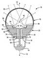
도 1은 본 발명의 제1실시예에 따른 조명 조립체의 단면도이다.
도 2A는 본 발명에 따른 회로 기판의 평면도이다.
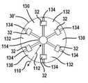
도 2B는 다른 예의 평면도이다.
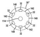
도 2C는 또 다른 예의 평면도이다.
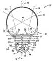
도 3A는 본 발명의 제2실시예에 따른 조명 조립체의 단면도이다.
도 3B는 도 3A에 도시된 히트 싱크의 핀(Fin)을 나타낸 평면도이다.
도 4A는 타원의 측면도이다.
도 4B는 타원면의 일부를 나타낸 단면도이다.
도 5는 본 발명의 제3실시예를 나타낸 단면도이다.
도 6은 본 발명의 제4실시예에 따른 조명 조립체의 단면도이다.
도 7은 본 발명의 제5실시예에 따른 조명 조립체의 단면도이다.
도 8은 본 발명의 제6실시예를 나타낸 단면도이다.
도 8A는 광 변화 부재와 필터의 확대 단면도이다.
도 9는 본 발명의 제7실시예를 나타낸 단면도이다.
도 10은 도 9의 10-10선 단면도이다.
도 11은 광 전향 부재와 같은 반사판을 포함하는 본 발명의 다른 실시예를 나타낸 단면도이다.
도 12는 회로 기판 내에 홈이 형성된 광 전향 부재와 같은 표면을 가진 조명 조립체의 단면도이다.
도 12A는 도 12에 도시된 광원의 확대 단면도이다.
도 12B는 도 12에 도시된 광원의 다른 단면도이다.
도 13은 그 안에 원통형 제어 회로를 가진 조명 조립체의 단면도이다.
도 14는 도 13에 도시된 제어 회로의 단면도이다.
도 15는 본 발명에 따른 관형상 조명 조립체의 단면도이다.
도 16은 도 15에 도시된 조명 조립체의 사시도이다.
도 17은 도 15에 도시된 조명 조립체의 길이방향 단면도이다.
도 18은 도 15와 다른 실시예를 가진 관형상 조명 조립체의 단면도이다.
도 19A는 본 발명에 따른 스포트라이트(Spotlight)로 사용하기 위한 조명 조립체의 단면도이다.
도 19B는 회로 트레이스(Trace)를 포함하는 반사판의 반사 표면 중 일부를 나타낸 도면이다.
도 20은 도 19에 도시된 것의 대안으로서, 각진 부분과 연장부를 나타낸 확대도이다.
도 21은 다른 광 전향 부재를 가진 각진 부분과 연장부를 나타낸 단면도이다.
도 22는 하우징의 일부를 나타낸 확대 단면도이다.
도 23은 제어 회로를 위한 다른 배치를 갖는 조명 조립체의 다른 실시예를 나타낸 도면이다.
도 24는 베이스 내에 장착된 직사각형 회로 기판을 포함하는 조명 조립체의 다른 실시예를 나타낸 측면도이다.
도 25는 베이스 내 회로 기판의 일부를 나타낸, 도 24의 25-25선 단면도이다.
도 26은 광원의 회로 기판에 관계된 제어 회로 기판의 평면도이다.
도 27은 본 발명에 따라 형성된 램프 베이스의 측면도이다.
도 28은 도 24에 도시된 히트 싱크 조립체의 절개 사시도이다.
대응하는 참조부호가 여러 도면에 걸쳐 대응하는 구성요소를 표시한다.It is to be understood that the drawings described herein are for illustrative purposes only and are not intended to be limiting of the scope of the present invention.
1 is a cross-sectional view of a lighting assembly according to a first embodiment of the present invention.
2A is a top view of a circuit board according to the present invention.
2B is a plan view of another example.
Figure 2C is a top view of yet another example.
3A is a cross-sectional view of a lighting assembly according to a second embodiment of the present invention.
3B is a plan view showing a fin of the heat sink shown in FIG. 3A.
4A is a side view of an ellipse.
4B is a sectional view showing a part of an elliptical surface.
5 is a cross-sectional view showing a third embodiment of the present invention.
6 is a cross-sectional view of a lighting assembly according to a fourth embodiment of the present invention.
7 is a cross-sectional view of a lighting assembly according to a fifth embodiment of the present invention.
8 is a sectional view showing a sixth embodiment of the present invention.
8A is an enlarged cross-sectional view of a light changing member and a filter.
9 is a sectional view showing a seventh embodiment of the present invention.
10 is a sectional view taken along the line 10-10 in Fig.
11 is a cross-sectional view showing another embodiment of the present invention including a reflector such as a light deflecting member.
12 is a cross-sectional view of a lighting assembly having a surface, such as a light deflecting member, in which a groove is formed in a circuit board.
12A is an enlarged sectional view of the light source shown in Fig.
12B is another sectional view of the light source shown in Fig.
13 is a cross-sectional view of a lighting assembly having a cylindrical control circuit therein.
14 is a cross-sectional view of the control circuit shown in Fig.
15 is a cross-sectional view of a tubular lighting assembly in accordance with the present invention.
16 is a perspective view of the illumination assembly shown in Fig.
17 is a longitudinal cross-sectional view of the illumination assembly shown in FIG.
18 is a cross-sectional view of a tubular lighting assembly with an embodiment that is different from that of FIG.
19A is a cross-sectional view of a lighting assembly for use as a spotlight in accordance with the present invention.
19B is a view showing a part of the reflective surface of the reflector including the circuit trace.
20 is an enlarged view showing an angled portion and an extension as an alternative to that shown in Fig.
FIG. 21 is a cross-sectional view showing an angled portion and an extended portion having another light transmitting member. FIG.
22 is an enlarged sectional view showing a part of the housing.
23 is a diagram illustrating another embodiment of a lighting assembly having a different arrangement for a control circuit.
24 is a side view illustrating another embodiment of a lighting assembly including a rectangular circuit board mounted within a base;
25 is a sectional view taken along the line 25-25 in Fig. 24 showing a part of the in-base circuit board.
26 is a plan view of a control circuit board related to a circuit board of a light source.
27 is a side view of a lamp base formed in accordance with the present invention.
28 is an exploded perspective view of the heat sink assembly shown in FIG.
Corresponding reference numerals designate corresponding components throughout the drawings.
아래의 설명은 전적으로 단순히 예시이며, 본 발명이나 응용 또는 용도를 제한하기 위한 것은 아니다. 보다 명확히 하기 위해, 동일한 참조 번호가 유사한 구성요소를 식별하도록 도면에 사용된다. 여기에 사용된 바와 같이, 문구 "A, B 및 C 중 적어도 하나"는 비배타적 논리합(OR)을 사용하여 (A 또는 B 또는 C) 논리를 의미하는 것으로 해석되어야 한다. 방법 내에 있는 단계는 본 발명의 원리를 변경하지 않고 다른 순서로 실행될 수 있는 것으로 이해되어야 한다.The following description is merely exemplary in nature and is not intended to limit the invention, its application, or uses. For clarity, like reference numerals are used in the drawings to identify like elements. As used herein, the phrase " at least one of A, B, and C " should be interpreted to mean logic (A or B or C) using a non-exclusive logical OR. It is to be understood that the steps within the methodology may be performed in a different order without altering the principles of the invention.
도면에서는, 다양한 구성요소가 상호 교환 가능하게 사용될 수 있다. 예를 들어, 제어 회로 기판과 광원 회로 기판의 여러 가지 다른 실시예가 구현된다. 뿐만 아니라, 광 전향 부재와 히트 싱크의 다양한 모양도 개시된다. 히트 싱크, 제어 회로 기판, 광원 회로 기판, 그리고 조명 조립체의 형상의 다양한 조합들이 이용될 수 있다. 다양한 유형의 인쇄된 트레이스와 재료가 조명 조립체의 여러 실시예에서 상호 교환 가능하게 사용될 수 있다.In the drawings, various components may be used interchangeably. For example, several different embodiments of a control circuit board and a light source circuit board are implemented. In addition, various shapes of the light deflecting member and the heat sink are also disclosed. Various combinations of shapes of the heat sink, control circuit board, light source circuit board, and lighting assembly may be used. Various types of printed traces and materials may be used interchangeably in various embodiments of the lighting assembly.
도면에서는, 다양한 파장을 가진 고체 레이저 및 LED와 같은 고체 광원을 포함한 다양한 실시예를 가진 조명 조립체를 도시하고 있다. 상이한 수의 광원과 상이한 수의 파장이, 조명 조립체의 궁극적인 용도에 따라 원하는 광 출력을 형성하도록 사용될 수 있다. 조명 조립체는 조명 장치에 대한 광학 - 열적 해결방안을 제공하며, 이러한 목적을 달성하기 위해 여러 형상을 이용한다.In the drawings, there is shown a light assembly having various embodiments including solid state light sources such as solid state lasers and LEDs having various wavelengths. Different numbers of light sources and different numbers of wavelengths may be used to form the desired light output depending on the ultimate use of the illumination assembly. The lighting assembly provides an optical-thermal solution for the lighting device, and uses various shapes to achieve this purpose.
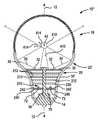
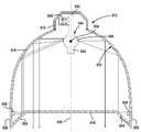
이제 도 1을 참조로 하면, 조명 조립체(10)의 단면은 도시되어 있다. 조명 조립체(10)는 길이방향 축(12) 주위로 회전 대칭일 수 있다. 조명 조립체(12)는 램프 베이스(14), 하우징(16), 및 커버(18)를 포함한다. 램프 베이스 또는 베이스(14)는 전구에 전기를 제공하는 데 사용된다. 베이스(14)는 용도에 따라 다양한 형상을 가질 수 있다. 그 형상은 표준 에디슨 베이스, 또는 더 크거나 작은 베이스와 같이 다양한 다른 유형이 포함될 수 있다. 베이스(14)는 나사, 클립, 플러그인 등을 포함한 다양한 유형일 수 있다. 베이스(14)는 전기 접촉을 형성하기 위해 적어도 부분적으로 금속으로 만들어질 수 있으며, 또한 열의 전도 및 분산에 사용될 수 있다. 또한, 베이스(14)는 세라믹, 열 전도성 플라스틱, 성형된 회로 커넥터가 있는 플라스틱, 또는 유사한 것 등에 제한되지 않는 재료로 만들어질 수 있다.Referring now to FIG. 1, a cross section of the
하우징(16)은 베이스(14)에 인접해 있다. 하우징(16)은 베이스(14)에 바로 인접하거나, 이들 사이에 중간부가 있을 수 있다. 하우징(16)은 금속 또는 다른 열 전도성 재료로 형성될 수 있다. 적당한 금속 중 한 예가 알루미늄이다. 하우징(16)은 스탬핑(Stamping)을 포함하는 다양한 방식으로 형성될 수 있다. 하우징(16)을 형성하는 또 다른 방법으로는 Zylor®과 같은 사출 성형된 금속을 포함한다. Thicksoform®의 성형도 사용될 수 있다. 하우징(16)은 쌍곡면부(20)와, 부분 타원체 또는 부분 포물면부(22)와 같은 다른 회전된 원뿔 형상부를 포함할 수 있다. 하우징(16)은 프리-폼(Free-Form) 형상으로 될 수도 있다.The
커버(18)는 부분 회전 타원체 또는 타원체의 형상으로 될 수 있다. 커버(18)는 유리나 플라스틱과 같은 투명 또는 반투명 재료로 형성될 수 있다. 커버(18)는 조명 조립체 내에 갇힌 후방 산란광(Backscattered Light)을 최소화하고 빛을 확산시키도록 될 수 있다. 커버(18)는 파장이나 확산과 같은 빛의 특성을 변경시키는 다양한 재료로 코팅될 수 있다. 반사 방지 코팅은 커버(18)의 안쪽에도 적용될 수 있다. 광원에 의해 펌핑되는 자체 발광 재료도 사용될 수 있다. 따라서, 조명 조립체(10)는 어둠 속에서의 색 지각(Color Perception) 및 높은 연색 평가 지수(Color Rendering Index)를 갖도록 형성될 수 있다. 하우징(16)과 커버(18)는 광원(32) 주변에 구획부를 형성한다. 베이스(14)도 구획부의 일부로 포함될 수 있다.The
조명 조립체(10)는 고체 광원(32)을 지지하는 데에 사용되는 기판이나 회로 기판(30)이 포함되어 있다. 회로 기판(30)은 후술하는 바와 같이 평면(도면 참조)으로 또는 만곡되게 형성될 수 있다. 회로 기판(30)은 열 전도성을 갖도록 될 수 있으며, 히트 싱크의 재료로 만들어질 수 있다. 광원의 솔더 패드(Solder Pad)는 플라스틱의 베이스에 이중 사출된(Over-Molded) 원형의 전도성 부재 또는 방사상으로 방위를 갖는 구리 섹터에 열적으로 또는 전기적으로 결합되어 열의 전도를 지원할 수 있다. 아래의 어떤 실시예에서는 회로 기판(30)이 히트 싱크의 일부가 될 수 있다.The
광원(32)은 높은 루멘 당 와트 출력을 갖는다. 광원(32)은 빛의 동일한 파장을 생성하거나 빛의 다른 파장을 생성할 수 있다. 광원(32)은 고체 레이저로 될 수도 있다. 고체 레이저는 평행광(Collimated Light)을 생성할 수 있다. 광원(32)은 LED로 될 수도 있다. 다른 파장을 생성하는 다양한 광원의 조합이 원하는 스펙트럼을 얻기 위해 사용될 수 있다. 적합한 파장의 예로는 자외선 또는 청색(예를 들면 450 ~ 470 nm)을 포함한다. 동일한 파장을 생성하는 다중 광원(32)도 사용될 수 있다. LED와 같은 광원(32)은 로우 앵글의 빛(34)과 하이 앵글의 빛(36)을 생성한다. 하이 앵글의 빛(36)은 커버(18)를 통해 밖으로 나아가게 된다.
종종 일반적인 전구에서, 로우 앵글의 빛은 이용가능한 방향으로 나아가지 않는 빛이다. 로우 앵글의 빛은, 이 빛이 조명 조립체가 결합되는 고정물의 밖으로 나아가지 않기 때문에 통상 버려진다.Often in a typical light bulb, low angle light is light that does not go in the available direction. The low-angle light is typically discarded because this light does not go out of the fixture to which the light assembly is coupled.
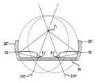
로우 앵글의 빛(34)은 반사판(40)을 사용하여 커버(18)의 밖으로 전향(Redirected)된다. 반사판(40)은 포물면, 타원체, 또는 프리-폼(Free-Form) 형상을 포함하는 다양한 모양으로 될 수 있다. 또한, 반사판(40)은 빛을 광원(32)으로부터 중심점 또는 공통점(42)으로 나아가게 하는 모양으로 될 수 있다. 반사판(40)은 파장 또는 에너지를 바꾸고 스펙트럼의 선택을 위한 코팅부를 갖출 수 있다. 코팅은 커버(18)와 반사판(40) 중 하나 또는 모두에 대해 이행될 수 있다. 다중 코팅도 이용될 수 있다. 공통점(42)은 커버(18)의 회전 타원체 또는 타원체의 중심이 될 수 있다.The low-
타원체, 포물면 또는 쌍곡면과 같은 다양한 원뿔 영역을 적용할 때 축을 중심으로 회전하는 원뿔 영역의 일부만 특정한 표면에 대해 사용될 수 있다. 유사한 방식으로, 회전 타원체의 일부가 사용될 수 있다.When applying various cone regions such as ellipsoid, paraboloid or hyperboloid, only a portion of the cone region rotating about the axis can be used for a particular surface. In a similar manner, a portion of a spheroid may be used.
후술하는 바와 같이, 회로 기판(30)은 히트 싱크(50) 또는 다른 회로 기판과 직접 접촉될 수 있다. 히트 싱크(50)는 조명 조립체(10)의 길이방향 축(12)에 직각인 방향으로 연장하면서 층을 형성하는 다수의 핀(Fin; 52)을 포함할 수 있다. 핀(52)들은 열이 분산되도록 하기 위해 이격될 수 있다. 또한, 히트 싱크(50)는 중앙부(54)를 포함할 수 있다. 후술하는 바와 같이, 중앙부(54)는 회로 기판(30) 또는 중앙의 제어 회로 기판과 접촉할 수 있다. 중앙부(54)는 이 중앙부를 관통하는 개구부(114)와 중앙부로부터 뻗은 핀(52)을 갖추고서 전체적으로 모양이 원통형으로 될 수 있다. 관통하는 개구부(114)는 그 안에 배치된 히트 스테이크(Heat Stake; 56)를 포함할 수 있다. 히트 스테이크(56)는 회로 기판(30)에 접촉하여, 중앙부(54)에 그리고 궁극적으로 핀(52)에 열을 전도할 수 있다. 또한, 히트 스테이크(56)는 램프 베이스(14)에 열을 전도할 수 있다. 히트 스테이크(56)도 핀(52)으로부터 열을 받을 수 있다.As will be described later, the
핀(52)은 모양이 평면으로 될 수 있다. 핀(52)의 평면은 길이방향 축에 직각으로 되며, 하우징(16)과 접촉할 수 있다. 다양한 설계 요인에 따라 핀(52)과 하우징(16) 사이의 직접적인 접촉은 필요하지 않을 수 있다. 하지만, 히트 싱크(50)의 핀(52)의 외측 선단은 하우징(16)과 접촉할 수 있다.The
따라서, 하우징(16)은 조명 조립체의 외부로 열을 분산시키기 위해 회로 기판의 광원(32)으로부터 멀리 열을 전도할 수 있다.Thus, the
추가 핀(58)이 회로 기판(30)의 위에 배치될 수 있다. 추가 핀(58)도 회로 기판(30)과 열의 전도가 이루어질 수 있다. 또한, 핀(58)은 반사판(40)을 지지할 수 있다. 핀(58)도 하우징(16)에 직접 또는 열적으로 접촉할 수 있다.
제어 회로 기판(70)도 조명 조립체(10) 내에 포함될 수 있다. 제어 회로 기판(70)이 평면과 원형으로 나타나 있다. 제어 회로 기판(70)의 다른 실시예에서는, 원통형 또는 길이방향의 방위를 갖는 회로 기판으로 구현될 수 있다. 제어 회로 기판(70)은 여러 모양으로 될 수 있다.The
제어 회로 기판(70)은, 광원(32)의 다양한 기능을 제어하는 데 사용할 수 있는 다양한 제어 칩(72)을 포함할 수 있다. 제어 칩(72)으로는 교류를 직류로 변환시키는 변환기, 디밍(Dimming) 회로, 원격 제어 회로, 저항기 및 커패시터와 같은 개별 구성요소들 및 전원 회로를 포함할 수 있다. 다양한 기능은 주문형 반도체(Application-Specific Integrated Circuit: ASIC)에 포함될 수 있다. 단지 하나의 제어 회로 기판(70)이 도시되어 있지만, 다중 회로 기판이 조명 조립체(10) 내에 구비될 수 있다. 제어 회로 기판(70)도 히트 스테이크(56)와 열의 전도가 이루어질 수 있다. 따라서, 히트 스테이크(56)는 제어 회로 기판(70)으로부터 램프 베이스(14) 쪽으로 또는 히트 스테이크(56)를 통해 중앙부(54) 및 핀(52)으로 열을 멀리 전도할 수 있다.The
이제 도 2a를 참조하면, 회로 기판(30)의 한 실시예가 도시되어 있다. 회로 기판(30)은 그 위에 다수의 광원(32)을 포함한다. 회로 기판(30)은 방사상 바깥쪽으로 향한 열 경로(110)와 방사상 안쪽으로 향한 열 경로(112)가 포함되어 있다. 개구부(114)는 회로 기판(30)을 통해 구비될 수 있다. 개구부(114)는 도 1에 도시된 바와 같이 이를 관통하는 히트 스테이크(56)를 가질 수 있다. 또한, 개구부(114)는 개방된 채로 남아 조명 조립체(10) 내에 공기 흐름 순환을 허용할 수도 있다. 개구부(114)는 하나 이상의 개구부로 바뀔 수 있다. 개구부는 회로 기판(30)에 전기적인 연결을 구성하기 위해 제어 회로 기판으로부터 나온 전선을 수용할 수 있는 크기로 될 수 있다. 이러한 실시예는 아래에 설명된다.Referring now to FIG. 2A, an embodiment of a
도 2a에는 광원(32)만 도시되어 있지만, 광원을 구동하기 위한 더 많은 전기 부품이 회로 기판(30)에 병합될 수 있다. 방열 비아(Thermal Via; 116)는 히트 싱크(50)에 열 경로를 허용하도록 회로 기판(30)에 걸쳐 구비될 수 있다. 도시된 바와 같이, 방열 비아(116)들은 전체적으로 삼각형 또는 파이 조각 배열로 놓이지만 열 경로(110, 112)를 방해하지 않는다. 방열 비아(116)는 광원의 바로 아래에 있을 수 있다.Although only the
회로 기판(30)은 열 전도성 기판을 형성하는 다양한 재료로 만들어질 수 있다. 광원의 솔더 패드는 플라스틱의 베이스에 이중 사출된 원형의 전도성 부재 또는 방사상으로 방위를 갖는 구리 섹터에 연결되어 광원으로부터 멀리 열을 전도할 수 있다. 광원의 구역에서 열을 제거함으로써, 조명 조립체(10)의 수명이 연장될 수 있다. 회로 기판(30)은 양면의 FR4 재료, 히트 싱크의 재료, 또는 이와 유사한 것들로 형성될 수 있다. 기판의 재료가 전기 전도성이면, 전기적인 트레이스(Trace)는 회로 기판의 전기 전도성 표면에 형성되는 비전도성 층에 형성될 수 있다.The
이제 도 2b를 참조하면, 회로 기판(30')의 다른 실시예가 도시되어 있다. 회로 기판(30')은 광원(32)에 전력을 제공하도록 교류 전원에 결합되는 다수의 회로 트레이스 섹터(130, 132)를 포함할 수 있다. 이들 섹터는 비전도성 틈새(134)로 구분된다. 광원(32)은 섹터(130, 132)와 번갈아 전기적으로 결합할 수 있다. 광원(32)은 두 섹터(130, 132)에 납땜이 되거나 전기적으로 다르게 장착될 수 있다.Referring now to FIG. 2B, another embodiment of the
각 섹터(130, 132)는 비전도성 회로 기판(30')에 배치될 수 있다. 전술된 바와 같이, 회로 기판(30')도 히트 싱크의 재료로 형성될 수 있다. 히트 싱크의 재료가 전기 전도성이라면, 비전도성 패드 또는 층이 섹터(130, 132)와 회로 기판(30') 사이에 위치될 수 있다.Each
개구부(114)가 원으로 나타나 있다. 또한, 개구부(114)는 제어 회로 기판에서 나온 전선을 결합시키기 위한 2개의 작은 개구부로 대체될 수 있다. 이러한 실시예는 추가로 아래에서 설명된다.The
이제 도 2c를 참조하면, 회로 기판(30")의 또 다른 실시예가 도시되어 있다. 회로 기판(30")은 회로 트레이스(140, 142)에 의해 이격되는 광원(32)이 포함되어 있다. 회로 트레이스(140, 142)는 광원(32)을 활성화하거나 이를 가능하게 하는 데에 사용되는 다른 전압을 가질 수 있다. 회로 트레이스(140, 142)는 히트 싱크의 기판과 같은 기판에 인쇄될 수 있다. 전기적인 연결이 제어 회로 기판과 이루어질 수 있다.2C, another embodiment of a
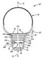
이제 도 3a 및 도 3b를 참조하면, 제2실시예에 따른 조명 조립체(10')가 도시되어 있다. 이 실시예에서는, 길이방향 축(12)과 베이스(14)는 유사하다. 하우징(16')은 도 1에 도시된 것과 같은 쌍곡면부(20)와 타원체부(22')를 포함할 수 있다. 타원체부(22')는 발광하는 광원(32)으로부터 방출된 로우 앵글의 빛(34)을 전향시키는 반사판으로 사용될 수 있다. 하우징(16')의 내부는 반사 표면으로 사용될 수 있다. 하우징(16')의 내부면은 양극산화 처리된 알루미늄(Anodized Aluminum) 또는 다른 반사 표면으로 될 수 있다. 하이 앵글의 빛(36)은 커버(18)를 통해 바로 투과된다. 공통점(42)은 타원체의 제1초점으로 되는 한편, 광원(32)의 링이 타원체의 제2초점을 형성할 수 있다. 광원의 링이 타원체의 제2초점으로 이용되기 때문에, 이 타원체는 오프셋 타원체라 할 수 있다. 타원체의 구성은 추가로 아래에서 설명된다.Referring now to Figures 3a and 3b, a lighting assembly 10 'in accordance with a second embodiment is shown. In this embodiment, the
이 실시예에서, 히트 싱크(210)는 도 1에 도시된 것과 상이한 방식으로 구성될 수 있다. 하지만, 도 1에 도시된 히트 싱크의 구성이 도 3a의 광학적 형태에 병합될 수 있다. 이 실시예에서, 다수의 히트 싱크의 핀(212)은 조명 조립체(10') 내에 배치된다. 히트 싱크(210)는 도 3b에 가장 잘 도시된 바와 같이 이를 관통하는 개구부(220)를 갖춘 다수의 디스크를 구비할 수 있다. 각 히트 싱크의 핀(212)은 와셔(Washer)와 닮을 수 있다. 히트 싱크의 핀(212)은 히트 스테이크(56), 그리고 하우징(16')의 포물면부 또는 쌍곡면부(20)와 열의 전도가 이루어질 수 있다. 각 히트 싱크의 핀(212)은 알루미늄 또는 구리와 같은 재료를 사용하여 등방성으로 열을 전도할 수 있다. 또한, 히트 싱크의 핀(212)은 흑연, 알루미늄 및 마그네슘과 같은 재료를 사용하여 비등방성으로 열을 전도할 수 있다. 히트 싱크(210)의 외경은 쌍곡면부(20)의 형상에 따라 변한다. 히트 싱크(210)의 핀(212)의 외측 선단(213)은 하우징(16')과 접촉할 수 있다. 디스크의 외곽선 또는 외형은 쌍곡면이다. 개구부(220)는 히트 스테이크(56)를 수용할 수 있거나, 후술되는 바와 같이 히트 스테이크(56)가 제거될 수 있다.In this embodiment, the
또한, 광원(32)은 히트 싱크의 핀(212)에 장착될 수 있다. 히트 싱크의 핀(212)은, 광원을 수용하고 상호 연결하기 위해 히트 싱크의 일부를 사용하여 전기적인 상호 연결부를 형성하도록 전도성 트레이스를 갖출 수 있다. 이것은 여기에 명시된 어떤 실시예에서 이루어질 수 있다.Also, the
하우징 내에서 노치(240, 242)가 히트 싱크의 핀(212)과 스냅 고정(Snap-Fit)될 수 있다. 도해의 단순화를 위해 하나의 하부 노치(240)와 하나의 상부 노치(242)만 나타나 있다. 하지만, 각각의 히트 싱크의 핀(212)과 회로 기판(30)은 유사한 방식으로 하우징에 고정될 수 있다. 히트 싱크의 핀(212)과 회로 기판(30)은 유연성이 있기 때문에, 적소에 히트 싱크의 핀(212)과 회로 기판(30)을 스냅 고정하는 것이 가능하다. 물론, 히트 싱크의 핀(212)과 회로 기판(30)을 고정하기 위한 다른 방법이 이용될 수 있다. 이것은 기계적인 고정구 또는 접착제를 사용하여, 히트 스테이크(56)에 회로 기판 및 히트 싱크의 핀을 고정하는 것과, 램프 베이스(14)에 히트 스테이크(56)를 고정하는 것을 포함할 수 있다.The
이제 도 4a를 참조하여, 전술된 이동 또는 오프셋 타원체를 형성하는 방법이 기술된다. 타원체는 두 초점(F1, F2)을 갖는다. 타원체는 또한 중심점(C)을 갖는다. 타원(308)의 장축(310)은 초점(F1과 F2)을 포함하는 선이다. 단축(312)은 장축(310)에 직각이고, 중심점(C)에서 장축(310)과 교차한다. 이동된 타원체를 형성하기 위해, 광원(32)에 해당하는 초점이 장축(310)에서 바깥쪽으로 이동하고, 초점(F1) 주위로 이동하거나 회전한다. 다음으로, 타원체가 회전하며, 타원체의 일부 표면이 반사 표면으로 사용된다. 각도(312)는 장치의 원하는 전체 기하학에 대응하는 다양한 각도로 될 수 있다. 타원에서, 초점(F2)에서 생성된 빛은 타원의 외부면(314)에 있는 반사판으로부터 반사되며, 초점(F1)에서 교차한다.Referring now to Figure 4a, a method of forming the above-described moving or offset ellipsoid is described. The ellipsoid has two foci (F1, F2). The ellipsoid also has a center point (C). The
이제 도 4b를 참조하면, 이동 또는 오프셋 타원체는 초점(F2', F2")에서 빛을 반사하여 초점(F1)에서 교차한다. 초점(F2', F2")은 광원(32)의 링에 있게 되는데, 그 로우 앵글의 빛은 이동된 타원체 표면으로부터 반사되고, 이 빛은 초점(F1)으로 나아간다. 따라서, 이제 초점(F2)이 초점(F2', F2")을 포함하는 링으로 되기 때문에, 타원체의 구성이 도 4b처럼 될 수 있다. 회로 기판(30)은 타원체부(22')에 결합될 수 있다. 본 발명의 일 실시예에서, 반사판은 부분 회전원뿔형을 가지며 타원의 장축이 미리결정된 각도로 이동된 이동 또는 오프셋 타원체를 형성하고 이동 또는 오프셋 타원체의 장축은 초점(F1)에 교차된 상태에서 광원의 링(32) 주위에서 회전할 수 있다.Referring now to Figure 4b, the moving or offset ellipsoid reflects light at focus F2 ', F2' 'and intersects at focus F1. Focuses F2' and F2 ' The light of the low angle is reflected from the surface of the moved ellipsoid, and the light advances to the focus F1. Therefore, the configuration of the ellipsoid can be as shown in Fig. 4B, since the focus F2 is now a ring including focal points F2 ', F2 ". The
도 1 또는 도 3a에 도시된 것에 해당하는 조명 조립체의 히트 싱크(210)가 사용될 수 있다.A
이제 도 5를 참조하면, 도 4b에 도시된 실시예와 유사한 실시예가 도시되어 있다. 이 실시예에서는, 하나 또는 다수의 스탠드 오프(Stand-Off; 410)가 광 변화 부재(412)를 지지하도록 구성되어 있다. 광원(32)으로부터 나오는 로우 앵글의 빛(34)은 공통점(42) 쪽으로 나아간다. 전술한 바와 같이, 공통점(42)은 커버(18)의 중심이고, 타원체부(22')의 초점으로 될 수 있다. 광 변화 부재(412)는 광 주파수(에너지)를 변화시키는 재료로 코팅되어, 로우 앵글의 빛이, 광 주파수의 원하는 출력 스펙트럼을 형성하도록 광원(32)으로부터 나오는 직광(Direct Light)에 추가되는 다른 빛의 특성을 구비하게 된다. 예를 들어, 광 변화 부재(412)는 원하는 스펙트럼의 분산을 달성하기 위해 형광체(Phosphors), 나노 형광체 또는 형광 염료로 코팅될 수 있다. 한 예를 들면, 청색광이 빛 또는 에너지 변화 재료와 접촉하게 될 때, 백색광과 같은 다른 색상으로 방출될 수 있는 청색 광원이나 레이저를 사용하는 것이 있다. 에너지는 광 변화 재료에 의해 흡수되고, 화살표(414)로 표시된 바와 같이 여러 방향으로 다시 방사될 수 있다. 하나의 광선이 광원(32)의 파장과 상이한 파장을 갖고서 여러 방향으로 산란될 수 있다. 광 변화 부재(412)는 금속과 같은 고체 재료로 되어 빛이 광 변화 부재에서 반사될 수 있다. 광 변화 부재(412)는 구체(球體) 또는 다른 형상으로 될 수 있다.Referring now to FIG. 5, there is shown an embodiment similar to the embodiment shown in FIG. 4B. In this embodiment, one or
이제 도 6을 참조하면, 히트 스테이크(56)가 각 히트 싱크의 핀(212)에 있는 개구부(114)에서 제거된 점만 제외하고, 도 3a와 유사한 조명 조립체(10"')의 실시예가 도시되어 있다. 도 3a에 도시된 히트 스테이크(56)의 위치에서, 개구부(114)는 히트 싱크의 핀(212) 내에서 개방된 채로 남아 있어, 공기가 조명 조립체(10"') 내에서 순환할 수 있다. 또한, 개구부(114)는 회로 기판(70)의 개구부(220)와 정렬되어, 조명 조립체(10"') 내의 열을 분산시키도록 공기가 순환할 수 있다. 예를 들어, 필름(600)과 같은 광 변화 부재는 조명 조립체 내에 배치된 파장 변화 부재로서 파장 변화 필름일 수 있다. 상기 파장 변화 부재는 구획부 내에 배치될 수 있고, 상기 파장 변화 부재는 상기 커버에 인접한 제 1파장 변화 비율과, 상기 제1 파장 변화 비율보다 놓고 상기 중심점에 인접한 제2 파장 변화 비율을 가진 파장 변화 기울기를 갖는 재료를 포함할 수 있다. 파장 변화 부재는 제1 초점과 다수의 LED 사이에 배치될 수 있다. 파장 변화 부재는 구체이거나, 회로 기판에 결합된 돔을 구비할 수 있다. 또한 회고 기판으로부터 뻗은 스탠드 오프를 사용하여 공통의 제1초점에 파장 변화 부재, 예를 들어, 구체의 파장 변화 부재를 위치시킬 수 있다.6, an embodiment of a
이제 도 7을 참조하면, 도 3a에 도시된 것과 유사한 조명 조립체(10ⅳ)의 실시예가 도시되어 있어서, 공통의 참조 부호는 더 설명되지 않는다. 이 실시예에서는, 돔(Dome; 510)과 같은 광 변화 부재가 나타나 있다. 돔(510)은 전술된 바와 같은 주파수 변화 또는 확산 재료를 포함할 수 있다. 필름이나 코팅부가 돔(510)에 적용되어, 빛의 변화 또는 빛의 주파수의 확산을 제공할 수 있다.Referring now to FIG. 7, there is shown an embodiment of a
위 또는 아래에 기술된 어떤 실시예에서는 돔(510)과 같은 광 변화 부재를 포함할 수 있다. 돔(510)은 광 필터 층(512)과 광 변화 층(514)을 포함하는 다양한 재료로 만들어질 수 있다. 광 필터 층(512)은 빛의 파장을 통과시키는 데에 사용될 수 있다. 파장은 광원(32)의 파장에 해당할 수 있다. 예를 들어, 광원(32)이 청색 레이저 또는 청색 LED이면, 필터(512)는 청색광을 통과시킬 수 있다. 광 변화 층(514)은 청색 이외의 다른 파장으로 빛의 파장을 변화시킬 수 있다. 예를 들어, 청색 파장은 광 변화 부재(514)를 활성화시켜 이로부터 백색광을 생성할 수 있다. 백색광은 직선으로 생성되거나 흩어질 수 있다. 산란광은 화살표(516)로 표시되어 있다. 물론 빛은 광원(32) 쪽으로 다시 흩어질 수 있다. 하지만, 광 필터 층(512)과 광 변화 층(514) 사이의 경계는 청색광을 제외한 모든 빛을 다시 반사할 수 있다. 필터(512)와 광 변화 층(514) 사이의 경계로부터 반사된 빛은 궁극적으로 커버(18)를 통해 빠져나간다.Such as
또한, 도 7에 도시된 실시예는 하우징(16') 내에 또는 하우징(16')을 통하는 관통구멍(520)을 포함한다. 관통구멍(520)은 핀(52)에 인접한 개구부로 되어, 조명 조립체(10ⅳ)로부터 열을 분산시키기 위한 외부 전도성 경로를 제공한다. 관통구멍(520)은 제조하는 동안 하우징(16') 내에 또는 하우징(16')을 통해 스탬핑 되거나 다른 방식으로 형성될 수 있다. 조명 조립체(10ⅳ)는 백열 전구와 같이 진공을 필요로 하지 않는다. 위 또는 아래에 기술된 어떤 실시예에서는 관통구멍(520)을 포함할 수 있다.In addition, the embodiment shown in FIG. 7 includes a through
이제 도 8을 참조로 하면, 도 3a에 도시된 것과 유사한 조명 조립체(10ⅴ)의 실시예가 도시되어 있다. 이 실시예에서는, 필름(600)과 같은 광 변화 부재가 커버(18)에 걸쳐 배치되어 있다. 모든 빛은 아니지만, 대부분의 빛은 광 변화 부재(600)를 통해 이동할 수 있으며 빛이 변화된다. 필름(600) 내에 있는 광 변화 재료의 양은 기울기에 따라 그 길이에 걸쳐 변경될 수 있다. 기울기는 필름의 중간 또는 중심(602) 쪽으로의 더 많은 광 변화와, 커버(18) 쪽으로의 더 적은 광 변화를 포함할 수 있다. 즉, 광 변화율이 커버에 인접한 제1비율과, 커버의 중심 근처에서 제1비율보다 높은 제2비율로 될 수 있다.Referring now to FIG. 8, an embodiment of a
회로 기판(30)에 대한 필름의 위치는 변화되는 광량(光量)에 의해 축(12)을 따라 바뀔 수 있다. 적은 빛이 변화되기를 원하면, 필름은 베이스(14)로부터 멀리 떨어져 커버(18)의 상부에 가까이 매달릴 수 있다. 모든 빛이 변화되기를 원하는 경우에는, 광 변화 부재(600)가 커버(18)와 하우징(16')의 접합지점(604) 근처에서 커버(18) 또는 하우징(16)에 걸쳐 매달릴 수 있다.The position of the film relative to the
이제 도 8a를 참조하면, 광 변화 부재(600)는 청색과 같은 파장을 위한 필터(606)에 형성될 수 있다. 광 변화 부재(600) 또는 더 정확히 광 변화 부재 내에 있는 입자나 요소가 광원의 방향을 포함하는 다양한 방향으로 빛을 산란시킬 수 있다. 필터가 광원과 동일한 필터 특성을 가지면, 빛이 광원으로부터 필터를 통해 보내어지게 된다. 광원 쪽으로 다시 방사된 빛은 광 변화 부재(600), 필터(606), 경계면(607)에서 반사되고, 광원으로부터 멀리 나아가게 된다. 청색광 또는 필터의 광투과 파장은 광원 쪽으로 다시 필터를 통과한다. 도시된 바와 같이, 광원으로부터 나온 빛(608)은 화살표(609)로 표시된 바와 같이 흩어지게 된다. 빛의 일부는 화살표(609")로 표시된 바와 같이 경계면(607)에서 반사될 수 있는 광선(609')으로 흩어지게 된다. 광 변화 부재(600)로부터 흩어져 필터(606)로 들어가는 빛은 광원(32)의 파장과 동일하다. 경계면(607)에서 반사된 빛은 파장 통과 재료 또는 대역 통과 필터(606)의 파장과 상이한 파장일 수 있다. 필터(606)는 광원(32)으로부터 나오면서 광 변화 부재(600)에 의해 흩어지는 빛의 파장을 통과시키는 대역 통과 필터로 될 수 있다. 이는 도 7에 대해 전술된 것과 유사하다. 광 변화 부재(600)와 필터(606)의 조합은 펌프라고 할 수 있는데, 이 예에서는 청색 펌프라 한다.Referring now to FIG. 8A, the
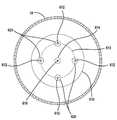
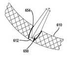
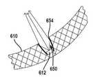
이제 도 9와 도 10을 참조하면, 조명 조립체(10ⅵ)의 실시예가 도시되어 있다. 이 실시예에서는 회로 기판(610)이 만곡된 형상 또는 부분 회전 타원체의 형상을 가질 수 있다. 회로 기판(610)은 절연층을 갖춘 금속 기판 또는 종래의 유리 섬유 회로 기판으로 될 수 있다. 회로 트레이스는 절연층에 형성된 다음 절연될 수 있다. 예를 들어, 양극산화 처리된 층을 가진 알루미늄 기판이 그 위에 회로 트레이스를 갖출 수 있다. 회로 트레이스는 절연체로 코팅될 수 있다. 회로 기판(610)은 평면으로 된 다음 가열되어 원하는 모양으로 성형될 수 있다.Referring now to Figures 9 and 10, an embodiment of a
회로 기판(610)은 그 위에 광원(612)을 포함하고 있다. 광원(612)은 전술되고 도 10에 도시된 바와 같이 원(613) 또는 링으로 배치될 수 있다. 원(613)은 각 광원(612)을 교차할 수 있다. 원(613)은 조명 조립체(10ⅵ)의 길이방향 축(12)에 직각인 평면 상에 배치될 수 있다. 전술된 바와 같이 커버(18)는 부분 회전 타원체로 될 수 있다. 커버(18)의 회전 타원체의 반경(R1)과 회로 기판(610)의 반경(R2)은 동일한 반경일 수 있다. 반경들(R1과 R2)도 동일하게 될 수 있다. 커버(18)도 타원체일 수 있다. 타원체의 중심은 커버(18)의 중심(616)에 상응할 수 있다. 광 변화 부재(614)는 회로 기판(610)의 회전 타원체의 중심(616)에 배치될 수 있다. 광 변화 부재(614)는 도 5에 도시된 것과 유사하게 될 수 있다. 즉, 광 변화 부재(614)는, 이 광 변화 부재(614)를 통해 이동하고 결국 커버(18)를 통해 투과되는 빛의 적어도 일부를 변화시키도록 그 위에 광 주파수 변화 코팅부 또는 필름(617)을 갖출 수 있다.The
도 9의 형태는 도 4a에서와 같이 형성되어, 중심(616)에 해당하는 F1과, 광원(612)에 해당하는 F2' 및 F2"를 가질 수 있다.9 may be formed as shown in FIG. 4A, and may have F1 corresponding to the
각 광원(612)은 빛을 광원(612)으로부터 중심(616)으로 초점을 모으도록 광 경로에 배치된 렌즈(620)와 같은 전향 부재를 포함할 수 있다. 렌즈(620)는 수렴 렌즈일 수 있다. 광원(612)은 회로 기판(610)의 회전 타원체의 표면에 대한 접선(618)에 평행할 수 있다. 광원의 중심축(624)을 따라 방출된 빛은 광 변화 부재(614)와 중심(616)을 교차한다. 중심축은 접선(618)에 직각이다. 따라서, 광원(612)에서 방출되는 임의의 빛이 중심(616)에서 수렴할 수 있다. 빛은 광 변화 부재(614)에 의해 변화된다. 물론, 각 렌즈는 광 변화 성능을 제공하기 위해 코팅될 수 있다. 따라서, 자외선이나 청색광을 이용하는 광원이 다양한 주파수로 변환되어 백색광을 제공할 수 있다.Each
광 변화 부재(614)는 스탠드 오프(630)를 이용하여 회로 기판(610)에서 지지될 수 있다. 스탠드 오프(630)는 히트 스테이크(56) 또는 도시된 바와 같이 회로 기판(610)에 직접 장착될 수도 있다.The
이제 도 11을 참조하면, 도 9 및 도 10과 유사한 실시예가 도시되어 있다. 이 실시예에서는 전향 부재로서 렌즈(620)가 반사판(640)으로 대체되어 있다. 반사판(640)은 타원체의 일부 또는 포물면의 일부인 표면을 가질 수 있다. 부분적으로 타원체인 모양은 각 광원(612)의 일부를 둘러쌀 수 있다. 광원(612)은 회전 타원체의 제1초점에 위치될 수 있으며, 반사판(640)에 대한 회전 타원체의 제2초점은 중심(616)일 수 있다. 이 역시 도 4a와 유사하여, F1은 중심(616)에 해당하고, F2'는 광원(612) 중 하나에 해당한다. 각 광원은 별개의 반사판(640)을 가질 수 있다.Referring now to FIG. 11, an embodiment similar to FIGS. 9 and 10 is shown. In this embodiment, the
이제 도 12, 도 12a, 도 12b를 참조하면, 도 9 및 도 10과 유사한 실시예가 도시되어 있다. 도 12에서, 도 11에 도시된 반사판(640)이 회로 기판(610) 내에 배치된 오목홈(650)으로 대체되어 있다. 회로 기판 내의 오목홈(650)은 회로 기판(610)을 관통하는 개구부(650) 또는 도 12b에 도시된 바와 같이 회로 기판(610)을 부분적으로 통하는 홈으로 될 수 있다. 개구부(650)는 인접한 반사판(654)을 갖춘 표면(652)을 구비할 수 있다. 반사판은 개구부(650)의 금속으로 피복된 선단의 별도의 구성요소로 될 수 있다. 반사판(654)은 타원체의 단면 또는 포물면 모양을 가진 회로 기판의 금속으로 피복된 표면일 수 있다. 금속으로 피복된 표면(614)은 회로 기판(610)의 선단(652)에 배치될 수 있다.Referring now to Figures 12, 12A and 12B, an embodiment similar to Figures 9 and 10 is shown. In Fig. 12, the
개구부(650)가 회로 기판(610)을 완전히 통하여 연장되지 않는 경우에, 광원(612)은 회로 기판(610)의 개구부(650)의 바닥면(654)에 부착될 수 있다. 도 12a에 도시된 바와 같이, 개구부(650)가 회로 기판(610)을 통해 연장하는 경우에, 광원(612)은 반사 표면(654) 또는 회로 기판(610)에 부착될 수 있다. 광원(612)에서 나온 빛이 반사 표면(654)에서 중심(616) 쪽으로 반사된다. 중심(616) 쪽으로 이동하는 빛이 광 변화 부재(614)에 의해 반사된다.The
이제 도 13을 참조하면, 소형화된 제어 회로 기판(70')이 도시된다. 히트 싱크의 핀을 통하는 개구부(708)가 확장될 수 있지만, 제어 회로 기판(70')은 조명 조립체 내의 히트 스테이크(56)를 대체할 수 있다. 제어 회로 기판(70')은 용도에 따라 다양한 구성요소를 포함할 수 있다. 한 구성요소가 AC-DC 변환기(710)일 수 있다. 다수의 저항(712) 및 커패시터(714)와 같은 다른 별개의 구성요소들도 제어 회로 기판(70')에 포함될 수 있다. 제어 회로 기판(70')은 교류 회로에 결합될 수 있는 입력 리드선(Lead; 716, 718)을 포함할 수 있다. 리드선(720, 722)은 직류 회로에 결합될 수 있다. 리드선(716, 718)은 회로 기판(701)의 금속 베이스(14)를 통해 결합하여 회로에 교류 전력을 제공할 수 있다. 리드선(720, 722)은 궁극적으로 회로 기판(30)과 광원(32)에 결합될 수 있다.Referring now to FIG. 13, a miniaturized control circuit board 70 'is shown. Although the
제어 회로 기판(70')과 히트 싱크의 핀(212) 사이에 있는 개구부(708)는 연속될 수 있다. 작은 핑거(Finger; 720)는 제어 회로 기판(70')을 지지하도록 히트 싱크의 핀(212)에서 연장할 수 있다. 핑거(720)는 축방향 지지를 제공하기에 충분히 크게 될 수 있지만, 제어 회로 기판(70')과 핀(212) 사이의 공기 흐름을 제공하도록 충분히 작을 수 있다.The
이제 도 14를 참조하면, 제어 회로 기판(70')은 조명 조립체의 길이방향 축(12)에 직각으로 주어진 단면도로 도시되어 있다. 도시된 바와 같이, 구성요소(710, 712 및 714)가 원통형으로 형성되어 있는 회로 기판(730)에 배치될 수 있다. 회로 기판(730)은 전술된 바와 같이 섬유 유리 회로 기판 또는 금속 기판을 포함한 다양한 종류의 회로 기판으로 될 수 있다.Referring now to Fig. 14, the control circuit board 70 ' is shown in cross-section taken at right angles to the
회로 기판이 형성된 후 회로 기판(730)은 에폭시(732)로 채워질 수 있다. 즉, 제어 회로 기판(70')이 안착되고 원통형으로 형성될 수 있다. 장치가 전기적인 구성요소로 채워지기 전이나 후에 원통형 모양이 형성될 수 있다. 실질적으로 원통형의 전체 길이가 에폭시로 채워질 수 있다.After the circuit board is formed, the
회로 기판(730)은 제어 회로 기판(70')의 내부와 외관을 형성한다. 전기적인 구성요소들(710 ~ 714)은 제어 회로 기판(70')에 의해 형성된 원통형 벽의 내부에 위치된다. 이 내부는 에폭시(732)로 채워진다.The
도 14는 제어 회로 기판(70')과 히트 싱크의 핀(212) 사이에 있는 개구부 또는 공간을 보여준다. 제어 회로 기판(70')을 축방향으로 지지하는 핑거(720)도 도시되어 있다.14 shows an opening or space between the control circuit board 70 'and the
도 5, 도 7, 도 8 및 도 9에 도시된 것과 같이 커버(18)나 여러 위치에 있는 광 변화 부재도 도 13과 도 14에 도시된 조명 조립체 내에 병합될 수 있다.As shown in Figures 5, 7, 8 and 9, the
이제 도 15, 도 16 및 도 17을 참조하면, 관형상 조명 조립체(810)가 도시된다. 관형상 조명 조립체(810)는 반사 표면(812)을 포함한다. 반사 표면(812)은 포물선 모양으로 될 수 있다. 즉, 반사 표면(812)은 포물선 모양의 원통일 수 있다.Turning now to Figures 15, 16 and 17, a
조명 조립체(810)는 길이방향 축(814)을 포함한다. 광원(820)은 길이방향 축(814)을 따라 배치될 수 있다. 광원(820)에서 나온 빛은 반사 표면(812) 쪽으로 이동한다.The
반사 표면(812)은 포물선 모양으로 될 수 있다. 포물선 모양은 조명 조립체(810)의 길이방향 축(814)과 일치하는 초점 라인을 가지고 있다. 반사 표면(812)에서 반사되는 광선(830)이 평행하게 된다. 길이방향으로는 광선(830)이 확산된다.The
광 변화 부재(832)도 조명 조립체(810) 내에 배치될 수 있다. 도 15, 도 16 및 도 17에 도시된 바와 같이, 광 변화 부재(832)는 조명 조립체(810)를 가로질러 반사 표면(812)의 일측 선단에서 반사 표면(812)의 타측 선단으로 뻗어 있는 필름을 구비할 수 있다. 광 변화 부재(832)는 반사 표면 또는 하우징(834)에 결합될 수 있다. 광 변화 부재(832)는 커버(842)에도 결합될 수 있다.The
광 변화 부재(832)는 이와 관련된 광 선택(대역 통과 필터링 또는 간섭) 필름(833)을 갖출 수 있다. 즉, 필름(833)은 광원의 파장(청색 또는 UV와 같은)에 대해 파장 투과성을 가질 수 있다. 광 변화 부재(832)와 필름(833) 사이의 경계면은, 도 7과 도 8에서 전술된 바와 같이 선택한 파장과 상이한 파장을 반사한다.The
하우징(834)은 반원형 단면을 가진 원통형 하우징일 수 있다. 하우징(834)은 도 15에 도시된 바와 같이 별개의 구성요소로 될 수 있거나, 도 18에 도시된 바와 같이 반사 표면(812)으로 되는 내부면과 외부면을 가진 단일한 구조물로 될 수 있다. 재료로는 금속, 플라스틱, 플라스틱에 금속을 입힌 것 또는 조합으로 될 수 있다.The
도 17에 가장 잘 도시된 바와 같이, 제어 회로(838)는 광원(820)으로의 전력을 제어하는 데 사용될 수 있다. 하나 이상의 제어 회로(838)가 관형상 조명 조립체(810) 내에 위치될 수 있다. 예를 들어, 제어 회로(838)는 관형상 조명 조립체(810)의 각 길이방향 끝에 위치될 수 있다. 제어 회로(838)는 광원(820)에 전력을 제공하기 위해 뻗어 있는 회로 트레이스(840)를 구비할 수 있다. 회로 트레이스(840)는 광 변화 부재(832)의 표면에 형성될 수 있다. 회로 트레이스(840)는 제어 회로(838)로부터 광원으로 결합된 별개의 전선일 수도 있다.As best shown in Fig. 17,
도 15에 도시된 바와 같이, 광 변화 부재(832)는 조명 조립체(810)의 직경을 가로질러 위치될 수 있다. 광원(820)은 길이방향 축(814)에 해당하는 관형상 조립체의 중심점에 위치될 수 있다. 따라서, 광 변화 부재(832)는 조명 조립체(810)의 길이를 따라 뻗은 평면을 형성할 수 있다.As shown in FIG. 15, the
또한, 광 변화 부재(832)는 커버(842)에 위치될 수 있다. 커버(842)도 모양이 원통형 또는 부분적으로 원통형일 수 있다. 커버(842)는 다양한 방향으로 빛을 확산시키는 확산성 코팅부를 갖출 수 있다.Further, the
이제 도 18을 참조하면, 도 15 내지 도 17의 실시예와 다른 실시예가 도시되어 있다. 이 실시예에서, 광원(820)은 조명 조립체(810')의 길이방향 축(814)에 위치하지 않는다. 광원(820)은 지지부 또는 다리부(846)를 사용하여 반사 표면(812) 위에 매달릴 수 있다. 다리부(846)는 하우징(834)이나 반사 표면(812)에서부터 연장할 수 있다.Referring now to Figure 18, there is shown an embodiment that is different from the embodiment of Figures 15-17. In this embodiment, the
또한, 반사 표면(812)은 3차원의 포물선 원통형 또는 포물선 단면으로 될 수 있다. 포물선 원통형(812)은 광원(820)과 교차하는 초점 라인(850)을 가질 수 있다. 따라서, 광원(820)에서 방출되는 빛은 포물선 표면(812) 쪽으로 이동하고 평행하게 된다.Also, the
다양한 수의 다리부(846)는 광원을 매달게 하는 데에 사용될 수 있다. 각 광원은 하나 이상의 다리부(846)에 의해 매달려 있거나 위치될 수 있다. 조명 조립체(810')도 전술한 바와 같이 커버(842)를 포함할 수 있다.The various numbers of
또, 조명 조립체(810')는 별도의 하우징(834)과 별도의 포물선 표면(812)을 포함할 수 있다. 조명 조립체(810')에 있는 다리부에 의해 매달려 있는 광원은 도 15, 도 16 및 도 17에 도시된 조명 조립체(810)에 사용될 수도 있다.In addition, the illumination assembly 810 'may include a
조명 조립체에 걸쳐 뻗어 있는 광 변화 부재(832)가 조명 조립체(810)에 있지만, 광 변화 부재는 커버(842)의 외부면(856) 또는 내부면(854)에 형성될 수 있다. 대부분의 광 변화 표면은 상업적인 실시예에서 커버(852)의 내부면(854)에 있게 된다.The light changing member may be formed on the
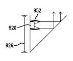
이제 도 19a를 참조하면, 조명 조립체(910)의 다른 실시예가 도시되어 있다. 이 실시예에서는, 조명 조립체가 스포트라이트 또는 다운라이트(Downlight)이다. 조명 조립체(910)는 베이스(912)와 하우징(914)을 포함한다. 베이스(912)는 전기 소켓에 클립 고정되거나 나사 체결될 수 있다. 하우징(914)은 후술하는 바와 같이 빛을 반사하는 데 사용된다. 조명 조립체(910)도 렌즈부(916)가 포함될 수 있다. 렌즈부(916)는 광 확산부 또는 매끄러운 표면을 구비할 수 있다. 렌즈부(916)는 필름을 갖출 수 있다.Referring now to Figure 19A, another embodiment of a
하우징(914)은 이에 부착된 광원(920)들을 갖출 수 있다. 광원(920)들은 베이스(912)의 반대편 위치에서 조명 조립체(910)의 주위로 이격될 수 있다. 광원(920)은 청색을 포함하여 빛의 다양한 파장을 생성할 수 있다. 광원의 전부 또는 일부는 빛의 동일한 파장을 방출할 수 있다. 이 예에서는 각 광원(920)이 청색광을 생성한다.The
하우징(914)은 이에 광원(920)들을 결합하기 위한 연장부(926)가 포함될 수 있다. 연장부(926)와 각진 부분(924)은 45도와 같은 고정된 관계를 가질 수 있다. 연장부(926)와 각진 부분(924) 사이에 관계된 각도는 고정되어, 후술하는 바와 같이 빛이 반사된다.The
하우징(914)은 포물선 모양으로 될 수 있다. 하우징(914)의 구성은 아래에 더 설명된다. 하지만, 하우징(914)에서 조명 조립체(910)의 내부는 반사 표면(930)을 포함할 수 있다. 반사 표면(930)은 초점(934)을 갖는다. 광원(920)은 평행광을 생성할 수 있거나, 도 20 및 도 21에 도시된 바와 같이 평행광을 생성하는 광 전향 부재를 갖출 수 있다. 평행광은 각진 부분(924)으로 나아간다. 평행광과 각진 부분(924)이 45도일 때, 평행광은 조명 조립체(910)의 길이방향 축(936)에 평행한 각도로 반사된다. 길이방향 축(936)에 평행한 방향으로 반사된 빛은 반사 표면(930)으로부터 초점(934) 쪽으로 반사된다.The
광 변화 부재(940)는 조명 조립체(910) 내에 결합한다. 이 실시예에서, 광 변화 부재(940)는 베이스(912)에 고정되게 결합한다. 하지만, 광 변화 부재 또한 하우징(914)에 결합될 수 있다. 광 변화 부재(940)는 제1원통부(942), 제2원통부(944) 및 회전 타원체부(946)를 포함한다. 제1원통부(942)가 베이스 또는 하우징(914)에 인접해 있다. 회전 타원체부(946)는 초점(934)과 일치하는 중심점을 갖는다. 길이방향 축(936)은 제1원통부(942)와 제2원통부(944)의 길이방향 축이며, 회전 타원체부(946)의 중심점(934)과 교차한다. 광 변화 부재(940)의 대부분 또는 일부는 광 변화 또는 에너지 변환 재료로 덮어 씌워질 수 있다. 예를 들어, 광 변화 재료는 청색광에서 백색광을 만들 수 있다. 각진 부분(924)에서 전향된 평행광은 광 변화 부재(940)로부터 반사되고, 또한 광 변화 부재(940)에서 파장 변화된다. 광 변화 부재(940)에서 반사된 빛은, 렌즈부(916)를 통해 빛을 전향시키는 하우징(914)의 반사 표면(930)으로 전향된다.The
각진 부분(924)은 금속이나 비투과성일 수 있다. 또한, 각진 부분(924)은 선택적 반사 표면으로 될 수 있다. 유리 또는 플라스틱이 파장 선택적 반사 표면으로 적절할 수 있다. 빛의 다른 파장이 반사될 수 있고 나머지는 통과할 수 있다. 파장 선택적 반사 표면은 여러 종류의 재료를 적용하여 형성될 수 있다. 각진 부분(924)은 광원(920)에 의해 방출된 파장을 반사하면서 광 변화 부재(940)에 의해 형성된 파장이 통과할 수 있는 유리 또는 플라스틱 재료로 형성될 수 있다. 위의 예에서, 광원(920)은 청색 파장의 빛을 방출하였다. 광 변화 부재(940)는 조명 조립체(910)를 떠날 때 각진 부분을 통과할 수 있는 백색광으로 청색 파장을 변환하였다.
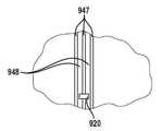
이제 도 19b를 참조하면, 광원(920)에 전력을 제공하는 하나의 방법이 기술된다. 전술한 바와 같이, 하우징(914)은 전기 전도성 혹은 전기 반사성 재료로 코팅된 플라스틱 재료로 만들어질 수 있다. 재료가 전기 전도성과 반사성 모두인 경우, 하우징(914)의 전체 표면은 이 재료로 코팅될 수 있으며 일부는 제거되어 그들 사이에 틈새(947)를 형성할 수 있다. 따라서, 틈새(947)는 광원(920)을 작동시키는 전압차를 제공하도록 상이한 전압에서 제어 회로(944)에 의해 구동될 수 있는 트레이스(948)를 형성할 수 있다. 복수의 광원(920)은 조명 조립체(910)의 외주 주위로 배치될 수 있다. 따라서, 한 쌍의 전도체(948)가 각 광원(920)에 구비될 수 있다. 폭에 대한 트레이스의 크기는 다양한 요구 사항에 따라 변화될 수 있다. 바람직하기로, 틈새(947)의 크기가 감소되어, 반사성 재료의 제거가 최소화된다. 제거되는 반사성 재료의 양을 최소화함으로써, 반사판은 최대의 반사량을 가질 수 있으며, 따라서 조명 조립체의 광 출력이 증가할 수 있다.Referring now to FIG. 19B, one method of providing power to
이제 도 20을 참조하면, 연장부(926)와 각진 부분(924)의 확대도가 도시되어 있다. 이 실시예에서, 렌즈(950)는 광 전향 부재로 사용된다. 렌즈(950)는 도 19에 도시된 조명 조립체(910)의 길이방향 축(936)에 직각인 방향으로 빛을 평행하게 한다. 각진 부분(924)에서 반사되는 빛은 길이방향 축(936)에 평행한 방향으로 반사된다.Referring now to FIG. 20, an enlarged view of the
이제 도 21을 참조하면, 광원(920)에 인접한 광 전향 부재는 반사판(952)으로 도시되어 있다. 반사판(952)은 광원(920)을 둘러싸거나 거의 둘러싼 포물선 또는 포물면 모양의 반사판으로 될 수 있다. 포물선 반사판(952)에서 반사된 빛은 길이방향 축(936)에 직각인 방향으로 평행하게 된다. 각진 부분(924)에 의해 반사된 빛은 길이방향 축(936)에 직각이다.Referring now to FIG. 21, the light deflecting member adjacent to
이제 도 22를 참조하면, 하우징(914)의 일부가 도시되어 있다. 하우징(914)은 다양한 재료로 형성되며, 그 안에 회로 트레이스(960)를 갖출 수 있다. 회로 트레이스(960)는 하우징(914)에 내장될 수 있다. 즉, 하우징(914)이 플라스틱 재료로 만들어질 수 있으며, 회로 트레이스(960)는 플라스틱 재료 내에 삽입될 수 있다. 회로 트레이스(960)는 광원(920)에 제어 회로(944)를 결합한다. 제어 회로(944)에서 각 광원(920)으로 연장하는 2 개의 전선은 하우징 내에 내장될 수 있다. 물론, 광원에 전력을 제공하는 다른 방법을 이용할 수 있다.Referring now to Figure 22, a portion of the
이제 도 23을 참조하면, 제어 회로(1012)를 갖춘 조명 조립체(1010)가 도시되어 있다. 조명 조립체(1010)는 램프 베이스(1014)를 포함한다. 램프 베이스(1014)는 조명 조립체의 바닥부(1016)에서 소정의 거리만큼 연장되는 측벽을 포함한다. 램프 베이스(1014)는 예컨대 에디슨(Edison) 램프 베이스로 될 수 있다. 램프 베이스(1014)는 소켓(미도시) 내에 램프 조립체(1010)를 고정하기 위한 나사산 또는 다른 기계적 구조물을 포함할 수 있다. 램프 베이스(1014)는 바닥부(1016) 및 측벽에 의해 둘러싸인 용적부를 형성한다.Referring now to FIG. 23, a
제어 회로(1012)는 광원 구동을 위한 드라이버를 포함하는 하나 이상의 회로 기판에 배치될 수 있다. 제어 회로(1012)는 조명 조립체(1010)의 하우징 또는 히트 스테이크(56) 내에 있는 다이렉트 와이어(Direct Wire) 또는 전선을 포함한 다양한 방식으로 광원(32)을 갖는 회로 기판(30)에 결합할 수 있다. 제어 회로(1014)는 AC-DC 변환 회로 및 다른 구성요소들도 포함할 수 있다.The
제어 회로(1012)는 램프 베이스의 용적부 내에 부분적으로 있을 수 있다. 또한, 제어 회로(1012)는 램프 베이스(1014) 내에 형성된 용적부 안에 전체가 배치될 수 있다. 또, 제어 회로(1012)는 램프 베이스(1014)의 용적부 내에서 에폭시로 덮어 씌워져 밀봉될 수 있다.The
도 1과 유사한 조명 조립체의 형태가 도시되어 있지만, 다른 도면에 도시된 조명 조립체의 구성이 여기에 병합될 수 있다. 즉, 램프 베이스의 용적부 내에 배치된 제어 회로(1012)는 전술된 어떤 실시예에 병합될 수 있다.Although the form of an illumination assembly similar to that of FIG. 1 is shown, the configuration of the illumination assembly shown in the other figures may be incorporated herein. That is, the
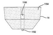
이제 도 24, 도 25 및 도 26을 참조하면, 조명 조립체(1100)의 또 다른 실시예가 도시되어 있다. 이 실시예는 위의 도 13에 도시된 실시예와 유사하고, 따라서 공통의 구성요소는 동일한 참조부호로 표시된다. 조명 조립체(1100)의 이 실시예에서는, 제어 회로 기판(1110)의 다른 실시예가 나타나 있다. 제어 회로 기판(1110)은 조명 조립체에 대한 제어를 형성하는 다양한 전기 부품을 포함할 수 있다. 전기 부품(1112)은 제어 회로 기판(1110)의 하나 이상의 측면에 부착될 수 있다. 전기 부품(1112)으로는 전술된 바와 같이 AC-DC 변환기, 저항, 전기 칩, 커패시터 및 기타 부재들을 포함하는 여러 종류의 구성요소로 될 수 있다.24, 25, and 26, another embodiment of a
도 25에 가장 잘 도시된 바와 같이 제어 회로 기판(1110)은 베이스(14) 내에 맞춤 고정될 있다. 이러한 맞춤 고정은 베이스(14)와 제어 회로 기판(1110) 사이의 억지끼워맞춤으로 될 수 있다. 특히, 한 쌍의 홈(1114)이 서로 베이스(14)의 맞은 편에서 옆으로 형성되어 제어 회로 기판(1110)이 그 안에 수용될 수 있다. 도 26에 가장 잘 도시된 바와 같이, 제어 회로 기판(1112)이 베이스(14) 내에서 반대 극성에 전기적으로 결합하기 위한 선단 커넥터(1116, 1118)를 포함할 수 있다. 홈(1114) 내의 억지끼워맞춤이 홈(1114) 내에 배치된 선단 커넥터(1116, 1118) 및 접속부(1120) 사이의 전기적 연결을 확보하도록 사용될 수 있다.As best seen in FIG. 25, the
베이스(14)는, 다른 부재들과 조합하여 광원에 독립적인 형태 및 기능을 형성하는 표준 에디슨 베이스로 될 수 있다. 즉, 베이스(14) 및 제어 회로 기판(1110)은 다양한 광원의 형태 및 광학 구조물과 함께 사용될 수 있다.The base 14 may be standard Edison-based, which, in combination with other members, forms a light source-independent shape and function. That is, the
도 26에 가장 잘 도시된 바와 같이, 제어 회로 기판(1110)은 이로부터 뻗은 전선(1130)을 포함할 수 있다. 전선(1130)은 회로 기판(30) 상의 광원(32)에 전력을 제공하는 데 사용될 수 있다. 납땜부(1132)는 회로 기판(30)에 위치된 회로 트레이스(1134)에 전선(1130)을 연결하는 데 사용될 수 있다. 납땜부(1132)에 덧붙여, 회로 트레이스(1134)에 전선(1130)을 연결하기 위한 다른 재료가 당해 분야의 숙련자들에게는 명확할 수 있다. 예를 들어, 전도성 잉크 또는 접착제가 사용될 수 있다. 회로 트레이스(1134)에 전선(1130)을 연결하기 위한 또 다른 방법으로는 와이어 본딩이 있다.As best shown in FIG. 26, the
도 24 내지 도 26에 도시된 실시예는 제조상의 장점이 있다. 베이스(14)가 형성될 수 있으며 회로 기판이 채워질 수 있다. 그 후에, 제어 회로 기판(1110)이 홈(1114) 내에 삽입되어 접속부(1120)가 선단 커넥터(1116 및 1118)에 전기적으로 연결될 수 있다. 다양한 형태의 전기 접속부가 사용될 수 있다. 중요한 점은 전기가 베이스(14)로부터 제어 회로 기판(1110)으로 공급된다는 점이다.The embodiment shown in Figs. 24-26 has manufacturing advantages. The base 14 can be formed and the circuit board can be filled. Thereafter, the
히트 싱크의 핀(1140)은 이들 히트 싱크의 핀(1140)을 함께 결합하는 중앙부(1142)를 갖출 수 있다. 중앙부(1142)도 회로 기판(30)을 향해 위쪽으로 연장할 수 있어, 회로 기판(30) 또한 히트 싱크 과정의 일부가 되게 한다. 히트 싱크(210)는 일체로 구성요소를 성형하거나 부품을 조립함으로써 미리 제조될 수 있다. 광원(32)은 조명 조립체(1100) 내에 삽입되기 전에 회로 기판(30)에 전기적으로 연결될 수 있다. 회로 기판(30)과 히트 싱크의 핀(1140)을 구성하는 조립체는 회로 기판 상에 놓여서, 전선(1130)이 회로 기판(30) 내 개구부(1172)를 통해 연장할 수 있다. 다음으로, 전선(1130)은 회로 기판(30)에서 회로 트레이스(1134)에 전기적으로 연결될 수 있다. 그 후에, 커버(18)가 조명 조립체 위에 놓이고 하우징(16')에 부착될 수 있다.The
이제 도 27을 참조하면, 베이스(14)의 실시예가 더욱 자세하게 도시되어 있다. 베이스(14)는 전기적인 접속부(1160)를 포함할 수 있다. 접속부(1160)는 전구가 놓이는 소켓과 충분한 전기적 접속을 제공한다. 다른 전기적인 접속부(미도시)가 바닥부 또는 바닥 접속부(1162)에 결합될 수 있다. 바닥 접속부(1162)와 연통하는 전기적인 접속부(1160)와 접속부(미도시)는 AC 회로에서 반대 극성으로 될 수 있다. 접속부들(1160, 1162)의 반대 극성은 제어 회로 기판(1110)에 전력을 제공할 수 있다. 도시된 바와 같이, 베이스(14)는 나사산(1164)을 갖춘 나사식 베이스로 될 수 있다. 하지만, 다양한 종류의 베이스가 전술한 바와 같이 사용될 수 있다. 접속부(1160)는 접속부(1120) 중 하나에 전기적으로 연결되어 있다. 접속부(1162)와 전기적으로 연통해 있는 전선 또는 트레이스는 맞은편 접속부(1120)와 연통하고 있다.Referring now to Figure 27, an embodiment of
이제 도 28을 참조하면, 히트 싱크(210)와 일체로 형성되는 회로 기판(30)을 포함하는 성형된 유닛의 예가 도시되어 있다. 도시된 바와 같이 히트 싱크는 중심부(1142)를 따라 핀(1140)이 포함되어 있다. 이 실시예에서, 회로 기판(30)은 히트 싱크의 핀과 동일한 재료로 형성된다. 회로 트레이스(1134)는 광원(32)을 구동하는 데 사용된다. 후술하는 바와 같이, 회로 기판(30)은 히트 싱크의 핀과 일체로 성형되거나 별도의 구성요소로 될 수 있다. 개구부(1170)는 그 안에 회로 기판을 수용하는 크기로 될 수 있다. 회로 기판(30)의 상부에 있는 개구부(1172)는 회로 기판(30)에서 나온 전선(1130)을 수용하는 데 사용될 수 있다. 회로 기판(30)은 그 위에 비전도성 부분과 회로 트레이스(1134)를 갖추면서 도 2a 내지 도 2c에 도시되고 전술된 다양한 방식으로 형성될 수 있다. 히트 싱크 조립체의 절반만 도시되어 있기 때문에, 다른 개구부(미도시)가 반대 극성을 갖는 전선(1130)을 위해 구비될 수 있다.28, an example of a molded unit including a
위의 실시예를 이용하여 다양한 구성요소가 호환될 수 있다. 예를 들어, 다양한 광 변화 기구가 하나의 파장에서 다른 파장으로 빛의 파장을 변경하는 데에 사용될 수 있다. 다양한 하우징 모양과 커버 모양도 호환될 수 있다. 마찬가지로, 다양한 램프 베이스도 사용될 수 있다. 제어 회로는 LED 또는 다른 광원을 제어하기 위한 다른 많은 종류의 실시예가 있을 수 있다. 다양한 종류 및 모양의 제어 회로가 각 실시예에서 사용될 수 있다. 전술한 바와 같이 히트 싱크 및 LED는 다양한 형태를 가질 수 있다. 히트 싱크는 와셔와 같은 구조로 될 수 있거나, 도 28에 도시된 바와 같이 일체화된 구조로 될 수 있다. 또한, 히트 싱크는 도 28과 같이 광원 회로 기판(30)과 일체로 될 수 있다. 광원 회로 기판(30)은 도 2a 또는 도 2b에 도시된 것을 포함한 다른 여러 실시예가 있을 수 있다. 이러한 형태도 도 28에 도시된 히트 싱크의 형태 내에 포함될 수 있다. 히트 스테이크를 사용하는 도 3a에 도시된 실시예와 히트 스테이크를 사용하지 않는 다른 실시예와 같이 열의 분산을 수행하는 다른 방법들이 조명 조립체의 다양한 형태와 병합될 수 있다. 또한, 전술된 관통구멍(520)도 전술된 어떤 실시예와 병합될 수 있다.Various components can be compatible using the above embodiment. For example, a variety of light changing mechanisms can be used to change the wavelength of light from one wavelength to another. Various housing shapes and cover shapes are also compatible. Likewise, various lamp bases may be used. The control circuitry may be many other types of embodiments for controlling LEDs or other light sources. Various types and shapes of control circuits can be used in each embodiment. As described above, the heat sink and the LED may have various shapes. The heat sink may have the same structure as the washer, or may have an integrated structure as shown in FIG. Further, the heat sink may be integrated with the light
실시예들의 전술한 설명은 도해와 설명의 목적으로 제공되었다. 이는 본 발명을 완전하게 이루어진 것으로 제한하기 위한 것이 아니다. 특정한 실시예의 개별적인 구성요소 또는 기능은 그 특정한 실시예에 한정되지 않고, 구체적으로 표시하거나 설명하지 않은 경우에도, 적용가능할 때 호환되며 선택된 실시예에서 사용될 수 있다. 또한, 여러 가지 방식으로 변경될 수 있다. 이러한 변경은 본 발명으로부터 벗어난 것으로 간주하지 않으며, 이러한 모든 수정은 본 발명의 범위 내에 포함될 것이다.The foregoing description of the embodiments has been presented for purposes of illustration and description. It is not intended to be exhaustive or to limit the invention to the precise forms disclosed. The individual components or functions of a particular embodiment are not limited to that particular embodiment, and may be used in selected and compatible embodiments where applicable, even if not specifically indicated or described. Also, it can be changed in various ways. Such variations are not to be regarded as a departure from the present invention, and all such modifications are intended to be included within the scope of the present invention.
Claims (187)
Translated fromKorean상기 베이스에 결합하는 하우징;
상기 하우징에 결합하는 커버;
상기 하우징 내에서 상기 하우징에 결합되고 빛을 생성하는 다수의 광원; 및
상기 광원에 전기적으로 결합되는 제1회로 기판 상에 배치되고, 상기 제1회로 기판은 상기 베이스 내부로 정의된 상기 용적부 내에 전체가 수용되고 상기 나사산에 인접하며, 상기 제1회로 기판은 그 가장자리에 제1 전기 접속부를 포함하는 제어 회로;
를 포함하되,
상기 전기 전도성인 베이스는 상기 측벽에 배치되어 상기 제1전기 접속부를 수용하되 억지끼워맞춤되도록 형성된 제2전기 접속부를 포함하는
조명 조립체.An electrically conductive base including a bottom portion and a sidewall including a threaded portion and defining a volume surrounded by the bottom portion and the sidewall;
A housing coupled to the base;
A cover coupled to the housing;
A plurality of light sources coupled to the housing within the housing and generating light; And
Wherein the first circuit board is entirely received within the volume defined within the base and is adjacent to the thread, the first circuit board having an edge A control circuit including a first electrical contact in the first electrical contact;
, ≪ / RTI &
Wherein the electrically conductive base includes a second electrical contact disposed on the sidewall and configured to receive and engage the first electrical contact
Lighting assembly.
상기 제어 회로는 상기 베이스 내에 밀봉되는 조명 조립체.The method according to claim 1,
Wherein the control circuit is sealed within the base.
상기 하우징 내에 배치되고, 상기 다수의 광원이 배치되되, 상기 제1회로 기판과 전기적으로 연결되는, 제2회로 기판을 더 포함하는
조명 조립체.The method according to claim 1,
Further comprising a second circuit board disposed in the housing and having the plurality of light sources disposed thereon and electrically connected to the first circuit board
Lighting assembly.
상기 다수의 광원과 열적으로 결합되는 히트 싱크를 더 포함하는
조명 조립체.The method according to claim 1,
Further comprising a heat sink thermally coupled to the plurality of light sources
Lighting assembly.
상기 조명 조립체의 길이방향 축을 둘러싸는 링에 상기 다수의 광원이 배치되는
조명 조립체.The method according to claim 1,
Wherein the plurality of light sources are disposed in a ring surrounding a longitudinal axis of the illumination assembly
Lighting assembly.
상기 다수의 광원은 고체 광원인
조명 조립체.The method according to claim 1,
The plurality of light sources is a solid light source
Lighting assembly.
상기 제1회로 기판은 전기 전도성인 상기 베이스 내에 형성되는 한 쌍의 홈에 수용되되,
상기 한 쌍의 홈은 상기 베이스의 외부와 전기적으로 연결되고, 상기 한 쌍의 홈은 상기 제1회로 기판에 배치된 한 쌍의 가장자리 접속부에 연결되는
조명 조립체.The method according to claim 1,
The first circuit board is accommodated in a pair of grooves formed in the base, which is electrically conductive,
Wherein the pair of grooves are electrically connected to the outside of the base, and the pair of grooves are connected to a pair of edge connecting portions disposed on the first circuit board
Lighting assembly.
상기 제1회로 기판은 상기 베이스의 하부 접속부에 전기적으로 연결되고,
상기 한 쌍의 홈은 상기 하부 접속부와 반대 극성을 갖는
조명 조립체.8. The method of claim 7,
The first circuit board is electrically connected to the lower connection portion of the base,
Wherein the pair of grooves has an opposite polarity to the lower connection portion
Lighting assembly.
상기 제어 회로는 광원 구동 드라이버를 포함하는
조명 조립체.The method according to claim 1,
Wherein the control circuit includes a light source driver
Lighting assembly.
Applications Claiming Priority (10)
| Application Number | Priority Date | Filing Date | Title |
|---|---|---|---|
| US22001909P | 2009-06-24 | 2009-06-24 | |
| US61/200,019 | 2009-06-24 | ||
| US61/220019 | 2009-06-24 | ||
| US26514909P | 2009-11-30 | 2009-11-30 | |
| US61/265149 | 2009-11-30 | ||
| US61/265,149 | 2009-11-30 | ||
| US12/817,807 | 2010-06-17 | ||
| US12/817807 | 2010-06-17 | ||
| US12/817,807US8186852B2 (en) | 2009-06-24 | 2010-06-17 | Opto-thermal solution for multi-utility solid state lighting device using conic section geometries |
| PCT/US2010/039509WO2011005526A2 (en) | 2009-06-24 | 2010-06-22 | Opto-thermal solution for multi-utility solid state lighting device using conic section geometries |
Related Parent Applications (1)
| Application Number | Title | Priority Date | Filing Date |
|---|---|---|---|
| KR1020127001726ADivisionKR101824729B1 (en) | 2009-06-24 | 2010-06-22 | Opto-thermal solution for multi-utility solid state lighting device using conic section geometries |
Publications (2)
| Publication Number | Publication Date |
|---|---|
| KR20180011889A KR20180011889A (en) | 2018-02-02 |
| KR101936045B1true KR101936045B1 (en) | 2019-01-08 |
Family
ID=43379911
Family Applications (2)
| Application Number | Title | Priority Date | Filing Date |
|---|---|---|---|
| KR1020187002514AExpired - Fee RelatedKR101936045B1 (en) | 2009-06-24 | 2010-06-22 | Opto-thermal solution for multi-utility solid state lighting device using conic section geometries |
| KR1020127001726AExpired - Fee RelatedKR101824729B1 (en) | 2009-06-24 | 2010-06-22 | Opto-thermal solution for multi-utility solid state lighting device using conic section geometries |
Family Applications After (1)
| Application Number | Title | Priority Date | Filing Date |
|---|---|---|---|
| KR1020127001726AExpired - Fee RelatedKR101824729B1 (en) | 2009-06-24 | 2010-06-22 | Opto-thermal solution for multi-utility solid state lighting device using conic section geometries |
Country Status (11)
| Country | Link |
|---|---|
| US (9) | US8186852B2 (en) |
| EP (2) | EP2446188B1 (en) |
| JP (1) | JP5759455B2 (en) |
| KR (2) | KR101936045B1 (en) |
| CN (4) | CN105299484B (en) |
| AR (1) | AR077216A1 (en) |
| BR (1) | BRPI1014839A2 (en) |
| CA (1) | CA2765711C (en) |
| MX (1) | MX2011013999A (en) |
| RU (1) | RU2547811C2 (en) |
| WO (1) | WO2011005526A2 (en) |
Families Citing this family (177)
| Publication number | Priority date | Publication date | Assignee | Title |
|---|---|---|---|---|
| US9412926B2 (en) | 2005-06-10 | 2016-08-09 | Cree, Inc. | High power solid-state lamp |
| US8186852B2 (en)* | 2009-06-24 | 2012-05-29 | Elumigen Llc | Opto-thermal solution for multi-utility solid state lighting device using conic section geometries |
| JP5317848B2 (en)* | 2009-06-25 | 2013-10-16 | 株式会社タキオン | LED lamp device |
| WO2011029154A1 (en)* | 2009-09-10 | 2011-03-17 | Hamish Mclennan | Improved light emitting diode (led) assembly and method of manufacturing the same |
| US8466611B2 (en)* | 2009-12-14 | 2013-06-18 | Cree, Inc. | Lighting device with shaped remote phosphor |
| CN201615365U (en)* | 2010-01-11 | 2010-10-27 | 敬祥科技股份有限公司 | Lamp decoration |
| US9453617B2 (en)* | 2010-02-08 | 2016-09-27 | Ban P. Loh | LED light device with improved thermal and optical characteristics |
| US8931933B2 (en) | 2010-03-03 | 2015-01-13 | Cree, Inc. | LED lamp with active cooling element |
| US9275979B2 (en)* | 2010-03-03 | 2016-03-01 | Cree, Inc. | Enhanced color rendering index emitter through phosphor separation |
| US9625105B2 (en) | 2010-03-03 | 2017-04-18 | Cree, Inc. | LED lamp with active cooling element |
| US20110227102A1 (en)* | 2010-03-03 | 2011-09-22 | Cree, Inc. | High efficacy led lamp with remote phosphor and diffuser configuration |
| US9316361B2 (en) | 2010-03-03 | 2016-04-19 | Cree, Inc. | LED lamp with remote phosphor and diffuser configuration |
| US9500325B2 (en) | 2010-03-03 | 2016-11-22 | Cree, Inc. | LED lamp incorporating remote phosphor with heat dissipation features |
| US8632196B2 (en)* | 2010-03-03 | 2014-01-21 | Cree, Inc. | LED lamp incorporating remote phosphor and diffuser with heat dissipation features |
| US9062830B2 (en) | 2010-03-03 | 2015-06-23 | Cree, Inc. | High efficiency solid state lamp and bulb |
| US9310030B2 (en)* | 2010-03-03 | 2016-04-12 | Cree, Inc. | Non-uniform diffuser to scatter light into uniform emission pattern |
| US9057511B2 (en) | 2010-03-03 | 2015-06-16 | Cree, Inc. | High efficiency solid state lamp and bulb |
| US9024517B2 (en) | 2010-03-03 | 2015-05-05 | Cree, Inc. | LED lamp with remote phosphor and diffuser configuration utilizing red emitters |
| US8882284B2 (en) | 2010-03-03 | 2014-11-11 | Cree, Inc. | LED lamp or bulb with remote phosphor and diffuser configuration with enhanced scattering properties |
| US8562161B2 (en) | 2010-03-03 | 2013-10-22 | Cree, Inc. | LED based pedestal-type lighting structure |
| US10359151B2 (en) | 2010-03-03 | 2019-07-23 | Ideal Industries Lighting Llc | Solid state lamp with thermal spreading elements and light directing optics |
| US9052067B2 (en) | 2010-12-22 | 2015-06-09 | Cree, Inc. | LED lamp with high color rendering index |
| US8393757B2 (en)* | 2010-03-04 | 2013-03-12 | Panasonic Corporation | Light-bulb type LED lamp and illumination apparatus |
| US20110260638A1 (en)* | 2010-04-26 | 2011-10-27 | Osram Sylvania Inc. | Reflector-type lamp with integrated heat distribution and emi shielding |
| US8461748B1 (en)* | 2010-04-29 | 2013-06-11 | Lights Of America, Inc. | LED lamp |
| US9157602B2 (en) | 2010-05-10 | 2015-10-13 | Cree, Inc. | Optical element for a light source and lighting system using same |
| US8596821B2 (en) | 2010-06-08 | 2013-12-03 | Cree, Inc. | LED light bulbs |
| US10451251B2 (en) | 2010-08-02 | 2019-10-22 | Ideal Industries Lighting, LLC | Solid state lamp with light directing optics and diffuser |
| US20120083159A1 (en)* | 2010-10-01 | 2012-04-05 | Tillman William R | Three Way Light Bulb Contact |
| US9279543B2 (en) | 2010-10-08 | 2016-03-08 | Cree, Inc. | LED package mount |
| WO2012052063A1 (en)* | 2010-10-22 | 2012-04-26 | Osram Ag | Led light source and associated structural unit |
| US9494297B1 (en)* | 2010-11-19 | 2016-11-15 | Continental Manufacturing, LLC | Solar-powered LED module and lighting fixtures |
| US8587185B2 (en) | 2010-12-08 | 2013-11-19 | Cree, Inc. | Linear LED lamp |
| CN102072428B (en)* | 2010-12-20 | 2013-05-08 | 鸿富锦精密工业(深圳)有限公司 | Light emitting diode (LED) daylight lamp |
| CN103415739B (en)* | 2010-12-30 | 2015-03-04 | 伊路米根有限责任公司 | Light assembly having light sources and adjacent light tubes |
| USD660990S1 (en) | 2011-01-19 | 2012-05-29 | Cree, Inc. | LED lamp |
| US9068701B2 (en) | 2012-01-26 | 2015-06-30 | Cree, Inc. | Lamp structure with remote LED light source |
| US9395057B2 (en)* | 2011-02-07 | 2016-07-19 | Cree, Inc. | Lighting device with flexibly coupled heatsinks |
| US9234655B2 (en) | 2011-02-07 | 2016-01-12 | Cree, Inc. | Lamp with remote LED light source and heat dissipating elements |
| US11251164B2 (en) | 2011-02-16 | 2022-02-15 | Creeled, Inc. | Multi-layer conversion material for down conversion in solid state lighting |
| GB2488982B (en)* | 2011-03-08 | 2014-10-08 | Teknologian Tutkimuskeskus Vtt Oy | Heat sink assembly for opto-electronic components and a method for producing the same LED heatsink |
| WO2012126498A1 (en)* | 2011-03-18 | 2012-09-27 | Osram Ag | Led light source and associated component |
| USD674129S1 (en)* | 2011-03-31 | 2013-01-08 | 3M Innovative Properties Company | Surface pattern applied to a light bulb |
| US20120250297A1 (en)* | 2011-04-04 | 2012-10-04 | Higgins John C | Light Assembly |
| US9316368B2 (en) | 2011-04-18 | 2016-04-19 | Cree, Inc. | LED luminaire including a thin phosphor layer applied to a remote reflector |
| US9470882B2 (en) | 2011-04-25 | 2016-10-18 | Cree, Inc. | Optical arrangement for a solid-state lamp |
| US8602577B2 (en) | 2011-04-25 | 2013-12-10 | Osram Sylvania Inc. | Side-emitting solid state light source modules with funnel-shaped phosphor surface |
| US10094548B2 (en) | 2011-05-09 | 2018-10-09 | Cree, Inc. | High efficiency LED lamp |
| US9797589B2 (en) | 2011-05-09 | 2017-10-24 | Cree, Inc. | High efficiency LED lamp |
| US8740424B2 (en)* | 2011-05-20 | 2014-06-03 | Goodrich Lighting Systems Gmbh | Light for an aircraft |
| BR112013031560A2 (en)* | 2011-06-09 | 2016-12-13 | Elumigen Llc | solid state lighting device using channels in a housing |
| US10203088B2 (en) | 2011-06-27 | 2019-02-12 | Cree, Inc. | Direct and back view LED lighting system |
| US20130003346A1 (en)* | 2011-06-28 | 2013-01-03 | Cree, Inc. | Compact high efficiency remote led module |
| WO2013009728A2 (en)* | 2011-07-12 | 2013-01-17 | Reliabulb, Llc | Led light bulb replicating the light pattern of an incandescent light bulb |
| CN102878445A (en)* | 2011-07-15 | 2013-01-16 | 欧司朗股份有限公司 | Luminous device |
| CN202176934U (en)* | 2011-07-20 | 2012-03-28 | 深圳市众明半导体照明有限公司 | LED (Light Emitting Diode) lamp and illumination equipment |
| US9534765B2 (en) | 2011-07-24 | 2017-01-03 | Cree, Inc. | Light fixture with coextruded components |
| US20130070462A1 (en)* | 2011-09-15 | 2013-03-21 | Xiao Ming Jin | Reflective lighting device |
| KR20130037945A (en)* | 2011-10-07 | 2013-04-17 | 삼성전자주식회사 | Lighting device |
| US8684565B2 (en)* | 2011-11-09 | 2014-04-01 | Cree, Inc. | LED light with active thermal management |
| DE102011086713A1 (en) | 2011-11-21 | 2013-05-23 | Osram Gmbh | Illuminating device with semiconductor light source and the claimed phosphor area |
| CN104025323B (en)* | 2011-12-21 | 2017-12-26 | 英特尔公司 | Heat management for light emitting diode |
| EP2801746A4 (en)* | 2011-12-30 | 2015-10-14 | Posco Led Co Ltd | Optical semiconductor lighting apparatus |
| US9482421B2 (en) | 2011-12-30 | 2016-11-01 | Cree, Inc. | Lamp with LED array and thermal coupling medium |
| US9476566B2 (en) | 2012-01-06 | 2016-10-25 | Cree, Inc. | Light fixture with textured reflector |
| US9488329B2 (en) | 2012-01-06 | 2016-11-08 | Cree, Inc. | Light fixture with textured reflector |
| CN103199370B (en)* | 2012-01-10 | 2016-09-28 | 欧司朗股份有限公司 | Connector, the electronic installation with this connector and illuminator |
| CN103206625A (en)* | 2012-01-16 | 2013-07-17 | 欧司朗股份有限公司 | Lighting device and manufacturing method thereof |
| TWI464348B (en)* | 2012-01-17 | 2014-12-11 | 南亞光電股份有限公司 | Tube type led lighting assembly |
| CN102588780A (en)* | 2012-01-18 | 2012-07-18 | 漳州市立达信绿色照明有限公司 | Large-angle LED lamp |
| US9512977B2 (en) | 2012-01-26 | 2016-12-06 | Cree, Inc. | Reduced contrast LED lighting system |
| US8480263B1 (en)* | 2012-02-15 | 2013-07-09 | Wen-Kung Sung | Heat dissipation structure of lighting device |
| KR101352053B1 (en) | 2012-03-20 | 2014-01-16 | 이용규 | Light reflecting device package and illumination device using the same |
| US9488359B2 (en) | 2012-03-26 | 2016-11-08 | Cree, Inc. | Passive phase change radiators for LED lamps and fixtures |
| US9022601B2 (en) | 2012-04-09 | 2015-05-05 | Cree, Inc. | Optical element including texturing to control beam width and color mixing |
| US9310028B2 (en) | 2012-04-13 | 2016-04-12 | Cree, Inc. | LED lamp with LEDs having a longitudinally directed emission profile |
| US9322543B2 (en) | 2012-04-13 | 2016-04-26 | Cree, Inc. | Gas cooled LED lamp with heat conductive submount |
| US9395074B2 (en) | 2012-04-13 | 2016-07-19 | Cree, Inc. | LED lamp with LED assembly on a heat sink tower |
| US9234638B2 (en) | 2012-04-13 | 2016-01-12 | Cree, Inc. | LED lamp with thermally conductive enclosure |
| US9410687B2 (en) | 2012-04-13 | 2016-08-09 | Cree, Inc. | LED lamp with filament style LED assembly |
| US9395051B2 (en) | 2012-04-13 | 2016-07-19 | Cree, Inc. | Gas cooled LED lamp |
| US8757839B2 (en) | 2012-04-13 | 2014-06-24 | Cree, Inc. | Gas cooled LED lamp |
| US9651240B2 (en) | 2013-11-14 | 2017-05-16 | Cree, Inc. | LED lamp |
| US9310065B2 (en) | 2012-04-13 | 2016-04-12 | Cree, Inc. | Gas cooled LED lamp |
| TWM437919U (en)* | 2012-05-11 | 2012-09-21 | Intematix Technology Ct Corp | Light emission device |
| WO2013175356A1 (en)* | 2012-05-24 | 2013-11-28 | Koninklijke Philips N.V. | Illumination device |
| DE102012209593B4 (en)* | 2012-06-06 | 2021-08-12 | Osram Gmbh | Lighting device |
| US8975616B2 (en)* | 2012-07-03 | 2015-03-10 | Liang Wang | Quantum efficiency of multiple quantum wells |
| MX344101B (en)* | 2012-07-10 | 2016-12-05 | Emergency Tech Inc | Emergency vehicle light fixture. |
| US9383146B2 (en)* | 2012-07-20 | 2016-07-05 | Tai-Her Yang | Heat dissipation device having lateral-spreading heat dissipating and shunting heat conductive structure |
| TWI498507B (en)* | 2012-08-08 | 2015-09-01 | Wintek Corp | Bulb lamp structure |
| US9097393B2 (en) | 2012-08-31 | 2015-08-04 | Cree, Inc. | LED based lamp assembly |
| US9097396B2 (en) | 2012-09-04 | 2015-08-04 | Cree, Inc. | LED based lighting system |
| DE102012218785A1 (en)* | 2012-10-16 | 2014-05-15 | Osram Gmbh | LAMP |
| US9134006B2 (en) | 2012-10-22 | 2015-09-15 | Cree, Inc. | Beam shaping lens and LED lighting system using same |
| US8911105B2 (en)* | 2012-11-01 | 2014-12-16 | Cree, Inc. | LED lamp with shaped light distribution |
| US9062867B2 (en) | 2012-12-12 | 2015-06-23 | Cree, Inc. | LED lamp |
| CN103062657B (en)* | 2012-12-30 | 2014-12-17 | 四川新力光源股份有限公司 | LED lighting with adjustable color temperature |
| US9570661B2 (en) | 2013-01-10 | 2017-02-14 | Cree, Inc. | Protective coating for LED lamp |
| US9303857B2 (en) | 2013-02-04 | 2016-04-05 | Cree, Inc. | LED lamp with omnidirectional light distribution |
| US9664369B2 (en) | 2013-03-13 | 2017-05-30 | Cree, Inc. | LED lamp |
| US9052093B2 (en) | 2013-03-14 | 2015-06-09 | Cree, Inc. | LED lamp and heat sink |
| US9115870B2 (en) | 2013-03-14 | 2015-08-25 | Cree, Inc. | LED lamp and hybrid reflector |
| US9243777B2 (en) | 2013-03-15 | 2016-01-26 | Cree, Inc. | Rare earth optical elements for LED lamp |
| US9506612B1 (en)* | 2013-03-15 | 2016-11-29 | Cooper Technologies Company | Emergency lighting for light emitting diode fixtures |
| US9657922B2 (en) | 2013-03-15 | 2017-05-23 | Cree, Inc. | Electrically insulative coatings for LED lamp and elements |
| US9435492B2 (en) | 2013-03-15 | 2016-09-06 | Cree, Inc. | LED luminaire with improved thermal management and novel LED interconnecting architecture |
| US10436432B2 (en)* | 2013-03-15 | 2019-10-08 | Cree, Inc. | Aluminum high bay light fixture having plurality of housings dissipating heat from light emitting elements |
| USD750317S1 (en) | 2013-03-15 | 2016-02-23 | Cree, Inc. | Bay lighting fixture |
| US20140268813A1 (en)* | 2013-03-15 | 2014-09-18 | Lightel Technologies Inc. | Lighting device with virtual light source |
| US10788177B2 (en) | 2013-03-15 | 2020-09-29 | Ideal Industries Lighting Llc | Lighting fixture with reflector and template PCB |
| US10527273B2 (en) | 2013-03-15 | 2020-01-07 | Ideal Industries Lighting, LLC | Lighting fixture with branching heat sink and thermal path separation |
| CN105308387A (en)* | 2013-03-26 | 2016-02-03 | 皇家飞利浦有限公司 | Lighting device |
| US9285082B2 (en) | 2013-03-28 | 2016-03-15 | Cree, Inc. | LED lamp with LED board heat sink |
| US10094523B2 (en) | 2013-04-19 | 2018-10-09 | Cree, Inc. | LED assembly |
| US9169977B2 (en) | 2013-06-28 | 2015-10-27 | Cree, Inc. | LED lamp |
| US9222659B2 (en) | 2013-06-28 | 2015-12-29 | Cree, Inc. | LED lamp |
| CN103383078A (en)* | 2013-07-08 | 2013-11-06 | 李忠凯 | A kind of LED lamp |
| USD740972S1 (en) | 2013-09-25 | 2015-10-13 | Cree, Inc. | Lamp |
| US9541241B2 (en) | 2013-10-03 | 2017-01-10 | Cree, Inc. | LED lamp |
| US10429052B2 (en) | 2013-10-24 | 2019-10-01 | Feit Electric Company, Inc. | LED lighting fixture |
| US9423116B2 (en) | 2013-12-11 | 2016-08-23 | Cree, Inc. | LED lamp and modular lighting system |
| US9726330B2 (en) | 2013-12-20 | 2017-08-08 | Cree, Inc. | LED lamp |
| US10030819B2 (en) | 2014-01-30 | 2018-07-24 | Cree, Inc. | LED lamp and heat sink |
| US9360188B2 (en) | 2014-02-20 | 2016-06-07 | Cree, Inc. | Remote phosphor element filled with transparent material and method for forming multisection optical elements |
| US9518704B2 (en) | 2014-02-25 | 2016-12-13 | Cree, Inc. | LED lamp with an interior electrical connection |
| US9759387B2 (en) | 2014-03-04 | 2017-09-12 | Cree, Inc. | Dual optical interface LED lamp |
| US20150252991A1 (en)* | 2014-03-06 | 2015-09-10 | Star Electrical Equipment Co., Ltd. | Standing pole type led light |
| US9328876B2 (en) | 2014-03-19 | 2016-05-03 | Cree, Inc. | High efficiency LED lamp |
| US9462651B2 (en) | 2014-03-24 | 2016-10-04 | Cree, Inc. | Three-way solid-state light bulb |
| US9927100B2 (en) | 2014-03-25 | 2018-03-27 | Cree, Inc. | LED lamp with LED board brace |
| US9765935B2 (en) | 2014-03-25 | 2017-09-19 | Cree, Inc. | LED lamp with LED board brace |
| US9388948B2 (en) | 2014-03-25 | 2016-07-12 | Cree, Inc. | LED lamp |
| US9328874B2 (en) | 2014-03-25 | 2016-05-03 | Cree, Inc. | LED lamp |
| US9562677B2 (en) | 2014-04-09 | 2017-02-07 | Cree, Inc. | LED lamp having at least two sectors |
| US9435528B2 (en) | 2014-04-16 | 2016-09-06 | Cree, Inc. | LED lamp with LED assembly retention member |
| US9488322B2 (en) | 2014-04-23 | 2016-11-08 | Cree, Inc. | LED lamp with LED board heat sink |
| US9618162B2 (en) | 2014-04-25 | 2017-04-11 | Cree, Inc. | LED lamp |
| US9951910B2 (en) | 2014-05-19 | 2018-04-24 | Cree, Inc. | LED lamp with base having a biased electrical interconnect |
| US9618163B2 (en) | 2014-06-17 | 2017-04-11 | Cree, Inc. | LED lamp with electronics board to submount connection |
| US9829179B2 (en) | 2014-06-26 | 2017-11-28 | Phillip Walesa | Parabolic quadrant LED light fixture |
| JP6667499B2 (en) | 2014-07-21 | 2020-03-18 | シグニファイ ホールディング ビー ヴィSignify Holding B.V. | Lighting device with virtual light source |
| US9488767B2 (en) | 2014-08-05 | 2016-11-08 | Cree, Inc. | LED based lighting system |
| US9651219B2 (en) | 2014-08-20 | 2017-05-16 | Elumigen Llc | Light bulb assembly having internal redirection element for improved directional light distribution |
| US20160084446A1 (en)* | 2014-09-23 | 2016-03-24 | Osram Sylvania Inc. | Tubular LED Lamp |
| US11215188B2 (en) | 2014-09-30 | 2022-01-04 | Sql Technologies Corp. | Apparatus including a combination of a ceiling fan and a heater with light effects |
| DE102014220276A1 (en)* | 2014-10-07 | 2016-04-07 | Osram Gmbh | lighting device |
| US10234129B2 (en)* | 2014-10-24 | 2019-03-19 | Lighting Science Group Corporation | Modular street lighting system |
| WO2016076330A1 (en)* | 2014-11-12 | 2016-05-19 | 武延 本郷 | Heat dissipation structure and illumination device |
| DE102014225486A1 (en)* | 2014-12-10 | 2016-06-16 | Osram Gmbh | Lamp with driver board and socket |
| US9909723B2 (en) | 2015-07-30 | 2018-03-06 | Cree, Inc. | Small form-factor LED lamp with color-controlled dimming |
| US10172215B2 (en) | 2015-03-13 | 2019-01-01 | Cree, Inc. | LED lamp with refracting optic element |
| US9702512B2 (en) | 2015-03-13 | 2017-07-11 | Cree, Inc. | Solid-state lamp with angular distribution optic |
| US10302278B2 (en) | 2015-04-09 | 2019-05-28 | Cree, Inc. | LED bulb with back-reflecting optic |
| WO2016183354A1 (en) | 2015-05-12 | 2016-11-17 | Kohen Ran Roland | Smart quick connect device for electrical fixtures |
| USD777354S1 (en) | 2015-05-26 | 2017-01-24 | Cree, Inc. | LED light bulb |
| US9890940B2 (en) | 2015-05-29 | 2018-02-13 | Cree, Inc. | LED board with peripheral thermal contact |
| US10180248B2 (en) | 2015-09-02 | 2019-01-15 | ProPhotonix Limited | LED lamp with sensing capabilities |
| RU2628762C2 (en)* | 2016-01-13 | 2017-08-22 | Юрий Борисович Соколов | Light-emitting-diode lamp for low-voltage electric circuit |
| CN105650489A (en)* | 2016-02-29 | 2016-06-08 | 柳州格瑞斯光电科技有限公司 | Luminous chip of LED mining lamp |
| CN105674096A (en)* | 2016-02-29 | 2016-06-15 | 柳州格瑞斯光电科技有限公司 | LED mining lamp |
| US10364944B2 (en) | 2016-12-15 | 2019-07-30 | Signify Holding B.V. | Visible and UV lighting system |
| ES2964013T3 (en) | 2017-03-05 | 2024-04-03 | Skyx Platforms Corp | Intelligent modular quick connect device for electrical accessories |
| EP3593418A4 (en) | 2017-03-10 | 2020-11-25 | Ran Roland Kohen | QUICK CONNECTION DEVICE FOR ELECTRIC RECESSED LUMINAIRES |
| CA3060544A1 (en) | 2017-04-17 | 2018-10-25 | Ran Roland Kohen | Disconnecting and supporting quick release electrical fixtures |
| US10260683B2 (en) | 2017-05-10 | 2019-04-16 | Cree, Inc. | Solid-state lamp with LED filaments having different CCT's |
| US10774994B2 (en)* | 2017-08-17 | 2020-09-15 | Leedarson America Inc. | Spotlight apparatus and manufacturing method thereof |
| US10274157B2 (en)* | 2017-08-17 | 2019-04-30 | Leedarson America Inc. | LED apparatus |
| JP6997060B2 (en)* | 2018-10-05 | 2022-01-17 | 日本碍子株式会社 | Infrared radiant device |
| KR102786992B1 (en) | 2019-02-20 | 2025-03-27 | 에스케이와이엑스 플랫폼 코포레이션 | Cross release attachment quick connect device |
| CN211344826U (en)* | 2019-09-17 | 2020-08-25 | 欧普照明股份有限公司 | Lamp body and bulb lamp |
| US12281783B2 (en) | 2019-12-31 | 2025-04-22 | Lumien Enterprise, Inc. | Electronic module group |
| US11598517B2 (en) | 2019-12-31 | 2023-03-07 | Lumien Enterprise, Inc. | Electronic module group |
| CN110985903B (en) | 2019-12-31 | 2020-08-14 | 江苏舒适照明有限公司 | Lamp module |
| KR20220161324A (en) | 2020-02-28 | 2022-12-06 | 에스케이와이엑스 플랫폼 코포레이션 | Recessed Smart Quick Connect Device |
| CN111503556B (en) | 2020-04-23 | 2020-11-27 | 江苏舒适照明有限公司 | a spotlight structure |
| US12230950B2 (en) | 2021-07-29 | 2025-02-18 | Lumien Enterprise, Inc. | Junction box |
Citations (5)
| Publication number | Priority date | Publication date | Assignee | Title |
|---|---|---|---|---|
| JP2003016805A (en) | 2001-06-28 | 2003-01-17 | Koichi Imai | Light, and method of manufacturing light |
| JP2004164879A (en) | 2002-11-11 | 2004-06-10 | Masao Yoshida | Illumination lamp having brilliant depiction image inside |
| JP2006156187A (en) | 2004-11-30 | 2006-06-15 | Mitsubishi Electric Corp | LED light source device and LED bulb |
| JP2008034140A (en) | 2006-07-26 | 2008-02-14 | Atex Co Ltd | Led lighting device |
| JP5815982B2 (en) | 2003-05-05 | 2015-11-17 | ジーイー ライティング ソリューションズ エルエルシー | LED light bulb |
Family Cites Families (169)
| Publication number | Priority date | Publication date | Assignee | Title |
|---|---|---|---|---|
| FR984607A (en) | 1949-02-15 | 1951-07-09 | Clair Echo | Gas discharge tube with combined reflector |
| GB1566447A (en)* | 1976-09-16 | 1980-04-30 | Luederitz W | Reflectors |
| JPH0416447Y2 (en)* | 1985-07-22 | 1992-04-13 | ||
| US5132875A (en)* | 1990-10-29 | 1992-07-21 | Compaq Computer Corporation | Removable protective heat sink for electronic components |
| US5654587A (en)* | 1993-07-15 | 1997-08-05 | Lsi Logic Corporation | Stackable heatsink structure for semiconductor devices |
| JPH09167508A (en)* | 1995-12-15 | 1997-06-24 | Patoraito:Kk | Signal informative display light |
| US5803579A (en)* | 1996-06-13 | 1998-09-08 | Gentex Corporation | Illuminator assembly incorporating light emitting diodes |
| US6045240A (en)* | 1996-06-27 | 2000-04-04 | Relume Corporation | LED lamp assembly with means to conduct heat away from the LEDS |
| US5803592A (en)* | 1996-11-22 | 1998-09-08 | Austin Air Systems Limited | Light source |
| US6965205B2 (en)* | 1997-08-26 | 2005-11-15 | Color Kinetics Incorporated | Light emitting diode based products |
| US6806659B1 (en)* | 1997-08-26 | 2004-10-19 | Color Kinetics, Incorporated | Multicolored LED lighting method and apparatus |
| US7014336B1 (en)* | 1999-11-18 | 2006-03-21 | Color Kinetics Incorporated | Systems and methods for generating and modulating illumination conditions |
| US6019493A (en)* | 1998-03-13 | 2000-02-01 | Kuo; Jeffrey | High efficiency light for use in a traffic signal light, using LED's |
| DE69912623T2 (en)* | 1998-09-04 | 2004-09-23 | Wynne Willson Gottelier Ltd., Tunbridge Wells | DEVICE AND METHOD FOR PROVIDING A LINEAR EFFECT |
| US6149283A (en)* | 1998-12-09 | 2000-11-21 | Rensselaer Polytechnic Institute (Rpi) | LED lamp with reflector and multicolor adjuster |
| JP2000268604A (en)* | 1999-03-19 | 2000-09-29 | Patoraito:Kk | Led indicating lamp |
| JP2001243809A (en) | 2000-02-28 | 2001-09-07 | Mitsubishi Electric Lighting Corp | Led electric bulb |
| US7320593B2 (en)* | 2000-03-08 | 2008-01-22 | Tir Systems Ltd. | Light emitting diode light source for curing dental composites |
| EP1146280B1 (en)* | 2000-04-12 | 2009-12-09 | WERMA Holding GmbH + Co. KG | Signalling device |
| JP3481599B2 (en)* | 2000-07-14 | 2003-12-22 | 京都電機器株式会社 | Linear lighting device |
| CN2444117Y (en) | 2000-08-08 | 2001-08-22 | 深圳市赛为实业有限公司 | Light-emititng diode monocolour lamp bulb |
| EP1221722A1 (en)* | 2001-01-06 | 2002-07-10 | Interuniversitair Microelektronica Centrum Vzw | Highly efficient paraboloid light emitting diode |
| KR20020091173A (en)* | 2001-02-02 | 2002-12-05 | 코닌클리즈케 필립스 일렉트로닉스 엔.브이. | Integrated light source |
| US7038399B2 (en)* | 2001-03-13 | 2006-05-02 | Color Kinetics Incorporated | Methods and apparatus for providing power to lighting devices |
| CH695956A5 (en)* | 2001-04-02 | 2006-10-31 | Agabekov Sa | Lighting element. |
| JP3753011B2 (en)* | 2001-04-11 | 2006-03-08 | 豊田合成株式会社 | Reflective light emitting diode |
| US6538892B2 (en)* | 2001-05-02 | 2003-03-25 | Graftech Inc. | Radial finned heat sink |
| FR2826098B1 (en)* | 2001-06-14 | 2003-12-26 | Valeo Vision | LIGHTING OR SIGNALING DEVICE, PARTICULARLY FOR VEHICLE, COMPRISING SEVERAL LIGHT SOURCES |
| WO2003006875A1 (en)* | 2001-07-10 | 2003-01-23 | Tsung-Wen Chan | A high intensity light source with variable colours |
| JP4129570B2 (en) | 2001-07-18 | 2008-08-06 | ラボ・スフィア株式会社 | Light emitting diode lighting device |
| US7192161B1 (en)* | 2001-10-18 | 2007-03-20 | Ilight Technologies, Inc. | Fluorescent illumination device |
| TW533750B (en)* | 2001-11-11 | 2003-05-21 | Solidlite Corp | LED lamp |
| TW515107B (en)* | 2001-12-25 | 2002-12-21 | Solidlite Corp | Power-saving light-emitting diode lamp |
| EP1467414A4 (en)* | 2001-12-29 | 2007-07-11 | Hangzhou Fuyang Xinying Dianzi | A led and led lamp |
| EP1461979B1 (en)* | 2002-01-07 | 2008-12-31 | Patent-Treuhand-Gesellschaft für elektrische Glühlampen mbH | Lamp |
| US6641284B2 (en)* | 2002-02-21 | 2003-11-04 | Whelen Engineering Company, Inc. | LED light assembly |
| DE10220292A1 (en)* | 2002-05-07 | 2003-11-27 | Philips Intellectual Property | Process for producing a luminescent material with a high thermal quenching temperature |
| US7358679B2 (en)* | 2002-05-09 | 2008-04-15 | Philips Solid-State Lighting Solutions, Inc. | Dimmable LED-based MR16 lighting apparatus and methods |
| US6871993B2 (en)* | 2002-07-01 | 2005-03-29 | Accu-Sort Systems, Inc. | Integrating LED illumination system for machine vision systems |
| US6827475B2 (en)* | 2002-09-09 | 2004-12-07 | Steven Robert Vetorino | LED light collection and uniform transmission system |
| US6896381B2 (en)* | 2002-10-11 | 2005-05-24 | Light Prescriptions Innovators, Llc | Compact folded-optics illumination lens |
| EP1411290A1 (en) | 2002-10-18 | 2004-04-21 | Altman Stage Lighting Co.,Inc. New York Corporation | Diode lighting system |
| US7011432B2 (en)* | 2002-11-05 | 2006-03-14 | Quarton, Inc. | Lighting source structure |
| US6840654B2 (en)* | 2002-11-20 | 2005-01-11 | Acolyte Technologies Corp. | LED light and reflector |
| USD494687S1 (en)* | 2003-01-27 | 2004-08-17 | Matsushita Electric Industrial Co., Ltd. | Light emitting diode lamp |
| US6767111B1 (en)* | 2003-02-26 | 2004-07-27 | Kuo-Yen Lai | Projection light source from light emitting diodes |
| JP2004265986A (en)* | 2003-02-28 | 2004-09-24 | Citizen Electronics Co Ltd | High brightness light emitting element, light emitting device using the same, and method of manufacturing high brightness light emitting element |
| US7556406B2 (en)* | 2003-03-31 | 2009-07-07 | Lumination Llc | Led light with active cooling |
| JP4335621B2 (en)* | 2003-04-25 | 2009-09-30 | スタンレー電気株式会社 | Vehicle lighting |
| DE10318932A1 (en)* | 2003-04-26 | 2004-11-25 | Aqua Signal Aktiengesellschaft Spezialleuchtenfabrik | Lantern, preferably for use on board ships, in particular on pleasure boats |
| US6864513B2 (en)* | 2003-05-07 | 2005-03-08 | Kaylu Industrial Corporation | Light emitting diode bulb having high heat dissipating efficiency |
| KR20040102301A (en)* | 2003-05-27 | 2004-12-04 | 삼성전자주식회사 | Illumination apparatus and Projection system employing assistant light source |
| WO2004111532A1 (en)* | 2003-06-16 | 2004-12-23 | Advanced Display Inc. | Planar light source device and display device using the same |
| KR101067738B1 (en)* | 2003-07-02 | 2011-09-28 | 에스.씨. 존슨 앤드 선, 인코포레이티드 | Lamp and Bulb for Illumination and Ambiance Lighting |
| US7604378B2 (en)* | 2003-07-02 | 2009-10-20 | S.C. Johnson & Son, Inc. | Color changing outdoor lights with active ingredient and sound emission |
| US20080106893A1 (en)* | 2004-07-02 | 2008-05-08 | S. C. Johnson & Son, Inc. | Lamp and bulb for illumination and ambiance lighting |
| US7246917B2 (en)* | 2003-08-12 | 2007-07-24 | Illumination Management Solutions, Inc. | Apparatus and method for using emitting diodes (LED) in a side-emitting device |
| DE10344547A1 (en) | 2003-09-24 | 2005-08-11 | Warnking Elektrotechnik Gmbh | Lamp |
| DE10345567A1 (en)* | 2003-09-29 | 2005-05-19 | Erco Leuchten Gmbh | Reflector luminaire, such as floor, ceiling or wall-mounted reflector luminaire, in particular stepped reflector luminaire |
| US6982518B2 (en)* | 2003-10-01 | 2006-01-03 | Enertron, Inc. | Methods and apparatus for an LED light |
| US6841804B1 (en)* | 2003-10-27 | 2005-01-11 | Formosa Epitaxy Incorporation | Device of white light-emitting diode |
| US7070301B2 (en)* | 2003-11-04 | 2006-07-04 | 3M Innovative Properties Company | Side reflector for illumination using light emitting diode |
| CN100492685C (en)* | 2003-12-05 | 2009-05-27 | 三菱电机株式会社 | Light emitting device and lighting fixture using the same |
| EP1704752A4 (en)* | 2003-12-11 | 2009-09-23 | Philips Solid State Lighting | Thermal management methods and apparatus for lighting devices |
| CN2681331Y (en)* | 2003-12-26 | 2005-02-23 | 鸿富锦精密工业(深圳)有限公司 | Heat sink |
| TWI233475B (en)* | 2004-01-20 | 2005-06-01 | Jau-Tang Lin | Lighting device with increased brightness |
| US7178937B2 (en)* | 2004-01-23 | 2007-02-20 | Mcdermott Vernon | Lighting device and method for lighting |
| US6948829B2 (en)* | 2004-01-28 | 2005-09-27 | Dialight Corporation | Light emitting diode (LED) light bulbs |
| KR200350484Y1 (en)* | 2004-02-06 | 2004-05-13 | 주식회사 대진디엠피 | Corn Type LED Light |
| CN2713286Y (en)* | 2004-03-02 | 2005-07-27 | 涂一波 | Bulb type organic light emitting diode lamp |
| AU2005219978B2 (en)* | 2004-03-03 | 2010-08-26 | S.C. Johnson & Son, Inc. | LED light bulb with active ingredient emission |
| US7172319B2 (en)* | 2004-03-30 | 2007-02-06 | Illumination Management Solutions, Inc. | Apparatus and method for improved illumination area fill |
| US7215086B2 (en)* | 2004-04-23 | 2007-05-08 | Lighting Science Group Corporation | Electronic light generating element light bulb |
| US7367692B2 (en)* | 2004-04-30 | 2008-05-06 | Lighting Science Group Corporation | Light bulb having surfaces for reflecting light produced by electronic light generating sources |
| US7319293B2 (en)* | 2004-04-30 | 2008-01-15 | Lighting Science Group Corporation | Light bulb having wide angle light dispersion using crystalline material |
| CN1722484A (en)* | 2004-07-16 | 2006-01-18 | 奥斯兰姆施尔凡尼亚公司 | Header devices for light-emitting diodes |
| DE102004042186B4 (en)* | 2004-08-31 | 2010-07-01 | Osram Opto Semiconductors Gmbh | Optoelectronic component |
| US7144131B2 (en)* | 2004-09-29 | 2006-12-05 | Advanced Optical Technologies, Llc | Optical system using LED coupled with phosphor-doped reflective materials |
| USD553266S1 (en)* | 2004-10-08 | 2007-10-16 | Lighting Science Group Corporation | LED light bulb |
| JP4424148B2 (en)* | 2004-10-13 | 2010-03-03 | 市光工業株式会社 | Projector-type vehicle headlamp unit |
| US7125160B2 (en)* | 2004-10-29 | 2006-10-24 | Applied Innovative Technologies, Inc. | Led light collection and uniform transmission system using a conical reflector with a roughed up inner surface |
| US20060098440A1 (en)* | 2004-11-05 | 2006-05-11 | David Allen | Solid state lighting device with improved thermal management, improved power management, adjustable intensity, and interchangable lenses |
| CN2767821Y (en)* | 2005-01-18 | 2006-03-29 | 陈凯柏 | Bulb with sensing function |
| ES2331750T3 (en)* | 2005-03-08 | 2010-01-14 | Grant Harold Amor | LED LIGHTING DEVICE (LIGHT EMITTER DIODE) IN A PLASTIC HOUSING. |
| WO2006104553A1 (en)* | 2005-03-25 | 2006-10-05 | Five Star Import Group L.L.C. | Led light bulb |
| US7758223B2 (en)* | 2005-04-08 | 2010-07-20 | Toshiba Lighting & Technology Corporation | Lamp having outer shell to radiate heat of light source |
| US7375476B2 (en)* | 2005-04-08 | 2008-05-20 | S.C. Johnson & Son, Inc. | Lighting device having a circuit including a plurality of light emitting diodes, and methods of controlling and calibrating lighting devices |
| US7226189B2 (en)* | 2005-04-15 | 2007-06-05 | Taiwan Oasis Technology Co., Ltd. | Light emitting diode illumination apparatus |
| US7445340B2 (en)* | 2005-05-19 | 2008-11-04 | 3M Innovative Properties Company | Polarized, LED-based illumination source |
| US7703951B2 (en)* | 2005-05-23 | 2010-04-27 | Philips Solid-State Lighting Solutions, Inc. | Modular LED-based lighting fixtures having socket engagement features |
| USD531740S1 (en)* | 2005-08-02 | 2006-11-07 | Lighting Science Group Corporation | LED light bulb |
| JP3787146B1 (en)* | 2005-08-30 | 2006-06-21 | 株式会社未来 | Lighting device |
| US7543959B2 (en)* | 2005-10-11 | 2009-06-09 | Philips Lumiled Lighting Company, Llc | Illumination system with optical concentrator and wavelength converting element |
| US7401948B2 (en)* | 2005-10-17 | 2008-07-22 | Visteon Global Technologies, Inc. | Near field lens having reduced size |
| CN101305242B (en)* | 2005-11-11 | 2013-04-03 | 皇家飞利浦电子股份有限公司 | Illuminators including LEDs |
| RU52258U1 (en)* | 2005-11-17 | 2006-03-10 | Открытое акционерное общество "Научно-исследовательский институт полупроводниковых приборов" (ОАО "НИИПП") | LED LAMP |
| USD532532S1 (en)* | 2005-11-18 | 2006-11-21 | Lighting Science Group Corporation | LED light bulb |
| US7850334B2 (en) | 2005-12-05 | 2010-12-14 | Illumination Management Solutions Inc. | Apparatus and method of using multiple LED light sources to generate a unitized beam |
| US7540616B2 (en)* | 2005-12-23 | 2009-06-02 | 3M Innovative Properties Company | Polarized, multicolor LED-based illumination source |
| JP2007173177A (en)* | 2005-12-26 | 2007-07-05 | Stanley Electric Co Ltd | Lighting device |
| US7465069B2 (en)* | 2006-01-13 | 2008-12-16 | Chia-Mao Li | High-power LED package structure |
| USD538950S1 (en)* | 2006-02-17 | 2007-03-20 | Lighting Science Group Corporation | LED light bulb |
| USD538952S1 (en)* | 2006-02-17 | 2007-03-20 | Lighting Science Group Corporation | LED light bulb |
| CN2886314Y (en)* | 2006-03-16 | 2007-04-04 | 宏齐科技股份有限公司 | Lamp module device |
| DE102007016951A1 (en)* | 2006-04-06 | 2007-10-18 | Continental Teves Ag & Co. Ohg | Method for determining unstable driving conditions |
| JP5052039B2 (en)* | 2006-05-22 | 2012-10-17 | 三菱電機株式会社 | Light source device |
| USD566323S1 (en)* | 2006-05-23 | 2008-04-08 | Philips Solid State Lighting Solutions, Inc. | Lighting apparatus frame |
| US7530710B2 (en)* | 2006-05-24 | 2009-05-12 | Patent-Treuhand-Gesellschaft für elektrische Glühlampen mbH | Color-tunable illumination system for imaging illumination |
| US7695164B2 (en)* | 2006-05-24 | 2010-04-13 | Osram Gesellschaft Mit Beschraenkter Haftung | Illumination system for imaging illumination with a high level of homogeneity |
| US7708452B2 (en)* | 2006-06-08 | 2010-05-04 | Lighting Science Group Corporation | Lighting apparatus including flexible power supply |
| US7614767B2 (en)* | 2006-06-09 | 2009-11-10 | Abl Ip Holding Llc | Networked architectural lighting with customizable color accents |
| US7482632B2 (en)* | 2006-07-12 | 2009-01-27 | Hong Kong Applied Science And Technology Research Institute Co., Ltd. | LED assembly and use thereof |
| US7738235B2 (en)* | 2006-07-31 | 2010-06-15 | B/E Aerospace, Inc. | LED light apparatus |
| DE102006037376A1 (en)* | 2006-08-09 | 2008-02-14 | Patent-Treuhand-Gesellschaft für elektrische Glühlampen mbH | lamp |
| DE102006044019B4 (en)* | 2006-09-15 | 2011-12-29 | Stiftung Alfred-Wegener-Institut für Polar- und Meeresforschung Stiftung des öffentlichen Rechts | reflector spotlight |
| US7547894B2 (en)* | 2006-09-15 | 2009-06-16 | Performance Indicator, L.L.C. | Phosphorescent compositions and methods for identification using the same |
| US7527397B2 (en)* | 2006-09-26 | 2009-05-05 | Chia-Mao Li | Solid state lighting package structure |
| US8104923B2 (en)* | 2006-10-12 | 2012-01-31 | Panasonic Corporation | Light-emitting apparatus |
| EP1914470B1 (en)* | 2006-10-20 | 2016-05-18 | OSRAM GmbH | Semiconductor lamp |
| US20080093998A1 (en)* | 2006-10-24 | 2008-04-24 | Led To Lite, Llc | Led and ceramic lamp |
| USD566309S1 (en)* | 2006-10-31 | 2008-04-08 | Leupold & Stevens, Inc. | Flashlight |
| US7883226B2 (en)* | 2007-03-05 | 2011-02-08 | Intematix Corporation | LED signal lamp |
| TWI433585B (en)* | 2007-12-03 | 2014-04-01 | Aeon Lighting Technology Inc | Three-dimensional miniaturized power supply |
| US7976182B2 (en)* | 2007-03-21 | 2011-07-12 | International Rectifier Corporation | LED lamp assembly with temperature control and method of making the same |
| US7841741B2 (en)* | 2007-04-02 | 2010-11-30 | Endicott Interconnect Technologies, Inc. | LED lighting assembly and lamp utilizing same |
| US20080295522A1 (en)* | 2007-05-25 | 2008-12-04 | David Allen Hubbell | Thermo-energy-management of solid-state devices |
| US7802903B1 (en)* | 2007-06-07 | 2010-09-28 | J&J Electronic, Inc. | LED festoon lighting |
| US7942556B2 (en)* | 2007-06-18 | 2011-05-17 | Xicato, Inc. | Solid state illumination device |
| US7868341B2 (en)* | 2007-06-27 | 2011-01-11 | The Regents Of The University Of California | Optical designs for high-efficacy white-light emitting diodes |
| US7607802B2 (en)* | 2007-07-23 | 2009-10-27 | Tamkang University | LED lamp instantly dissipating heat as effected by multiple-layer substrates |
| ATE445808T1 (en)* | 2007-08-02 | 2009-10-15 | Hartmut S Engel | LAMP |
| DE102007040444B8 (en)* | 2007-08-28 | 2013-10-17 | Osram Gmbh | Led lamp |
| US7963689B2 (en)* | 2007-10-24 | 2011-06-21 | Kun Dian Photoelectric Enterprise Co. | LED-edgelit light guide fixture having LED receiving grooves |
| JP2011023375A (en) | 2007-11-13 | 2011-02-03 | Helios Techno Holding Co Ltd | Light emitting device |
| USD584838S1 (en)* | 2007-11-28 | 2009-01-13 | Koninklijke Philips Electronics N.V. | Solid state lighting spot |
| WO2009071111A1 (en)* | 2007-12-07 | 2009-06-11 | Osram Gesellschaft mit beschränkter Haftung | Heat sink and lighting device comprising a heat sink |
| WO2009100160A1 (en)* | 2008-02-06 | 2009-08-13 | C. Crane Company, Inc. | Light emitting diode lighting device |
| CN201198987Y (en)* | 2008-02-29 | 2009-02-25 | 义乌市龙生照明科技有限公司 | A kind of LED fluorescent tube |
| CN101532646B (en)* | 2008-03-14 | 2012-06-13 | 富准精密工业(深圳)有限公司 | Illuminating apparatus |
| CN101270855A (en)* | 2008-04-16 | 2008-09-24 | 清华大学 | An LED-based surface light source lighting device |
| CN201190963Y (en)* | 2008-05-06 | 2009-02-04 | 和谐光电科技(泉州)有限公司 | Light supply apparatus using LED |
| US20090296387A1 (en)* | 2008-05-27 | 2009-12-03 | Sea Gull Lighting Products, Llc | Led retrofit light engine |
| US8021008B2 (en)* | 2008-05-27 | 2011-09-20 | Abl Ip Holding Llc | Solid state lighting using quantum dots in a liquid |
| US7905639B2 (en)* | 2008-05-28 | 2011-03-15 | Osram Sylvania Inc. | Side-loaded light emitting diode module for automotive rear combination lamps |
| EP2297273A4 (en)* | 2008-06-05 | 2012-06-06 | Performance Indicator Llc | Photoluminescent fibers, compositions and fabrics made therefrom |
| US7905634B2 (en)* | 2008-06-16 | 2011-03-15 | Light Prescriptions Innovators, Llc | Multi-reflector LED light source with cylindrical heat sink |
| DE102008028611B4 (en)* | 2008-06-18 | 2012-11-08 | Phoenix Contact Gmbh & Co. Kg | Luminous element with plastic holder |
| CN102175000B (en)* | 2008-07-30 | 2013-11-06 | 东芝照明技术株式会社 | Lamp and lighting equipment |
| CA2676315A1 (en)* | 2008-08-22 | 2010-02-22 | Virginia Optoelectronics, Inc. | Led lamp assembly |
| CN101660669A (en)* | 2008-08-28 | 2010-03-03 | 启萌科技有限公司 | Light-emitting unit |
| JP5263515B2 (en)* | 2008-10-20 | 2013-08-14 | 東芝ライテック株式会社 | Lighting device |
| CN101725946B (en)* | 2008-10-24 | 2012-11-21 | 富准精密工业(深圳)有限公司 | Light-emitting diode lamp |
| CN101725947A (en)* | 2008-10-27 | 2010-06-09 | 富准精密工业(深圳)有限公司 | Light-emitting diode lighting device |
| US20100103666A1 (en)* | 2008-10-28 | 2010-04-29 | Kun-Jung Chang | Led lamp bulb structure |
| CN101725937B (en)* | 2008-10-30 | 2012-06-13 | 富准精密工业(深圳)有限公司 | Light-emitting diode lamp |
| CN101725921B (en)* | 2008-10-30 | 2012-08-22 | 富准精密工业(深圳)有限公司 | Light-emitting diode lamp |
| KR100905502B1 (en)* | 2008-11-10 | 2009-07-01 | 현대통신 주식회사 | Led lighting device |
| US8004172B2 (en)* | 2008-11-18 | 2011-08-23 | Cree, Inc. | Semiconductor light emitting apparatus including elongated hollow wavelength conversion tubes and methods of assembling same |
| USD604434S1 (en)* | 2008-11-27 | 2009-11-17 | Toshiba Lighting & Technology Corporation | Light emitting diode lamp |
| JP5264448B2 (en)* | 2008-12-02 | 2013-08-14 | 株式会社小糸製作所 | Projection type vehicle lamp |
| US7923907B2 (en)* | 2009-01-19 | 2011-04-12 | Osram Sylvania Inc. | LED lamp assembly |
| JP2012518254A (en)* | 2009-02-17 | 2012-08-09 | カオ グループ、インク. | LED bulbs for space lighting |
| JP5333758B2 (en)* | 2009-02-27 | 2013-11-06 | 東芝ライテック株式会社 | Lighting device and lighting fixture |
| US7959322B2 (en)* | 2009-04-24 | 2011-06-14 | Whelen Engineering Company, Inc. | Optical system for LED array |
| KR101758188B1 (en)* | 2009-06-10 | 2017-07-14 | 렌슬러 폴리테크닉 인스티튜트 | Solid state light source light bulb |
| US8186852B2 (en)* | 2009-06-24 | 2012-05-29 | Elumigen Llc | Opto-thermal solution for multi-utility solid state lighting device using conic section geometries |
| US8047679B2 (en)* | 2009-09-30 | 2011-11-01 | Edison Opto Corporation | LED lamp with 360-degree illumination |
| US20110090669A1 (en)* | 2009-10-20 | 2011-04-21 | Tsung-Ting Sun | Led lighting device and light source module for the same |
| US8596821B2 (en)* | 2010-06-08 | 2013-12-03 | Cree, Inc. | LED light bulbs |
- 2010
- 2010-06-17USUS12/817,807patent/US8186852B2/ennot_activeExpired - Fee Related
- 2010-06-22RURU2012102320/07Apatent/RU2547811C2/ennot_activeIP Right Cessation
- 2010-06-22KRKR1020187002514Apatent/KR101936045B1/ennot_activeExpired - Fee Related
- 2010-06-22KRKR1020127001726Apatent/KR101824729B1/ennot_activeExpired - Fee Related
- 2010-06-22MXMX2011013999Apatent/MX2011013999A/enactiveIP Right Grant
- 2010-06-22EPEP10728093.5Apatent/EP2446188B1/ennot_activeNot-in-force
- 2010-06-22JPJP2012517656Apatent/JP5759455B2/ennot_activeExpired - Fee Related
- 2010-06-22BRBRPI1014839Apatent/BRPI1014839A2/ennot_activeIP Right Cessation
- 2010-06-22CNCN201510767967.7Apatent/CN105299484B/ennot_activeExpired - Fee Related
- 2010-06-22CACA2765711Apatent/CA2765711C/ennot_activeExpired - Fee Related
- 2010-06-22CNCN201080028308.7Apatent/CN102483213B/ennot_activeExpired - Fee Related
- 2010-06-22EPEP17162916.5Apatent/EP3208534A1/ennot_activeWithdrawn
- 2010-06-22CNCN201510766045.4Apatent/CN105402616B/ennot_activeExpired - Fee Related
- 2010-06-22WOPCT/US2010/039509patent/WO2011005526A2/enactiveApplication Filing
- 2010-06-22CNCN201410559918.XApatent/CN104595851A/enactivePending
- 2010-06-24ARARP100102228patent/AR077216A1/enunknown
- 2011
- 2011-06-29USUS13/172,379patent/US8277082B2/ennot_activeExpired - Fee Related
- 2011-06-29USUS13/172,480patent/US8449137B2/enactiveActive
- 2011-06-29USUS13/172,511patent/US8192057B2/ennot_activeExpired - Fee Related
- 2011-06-29USUS13/172,435patent/US20110254441A1/ennot_activeAbandoned
- 2011-06-29USUS13/172,236patent/US8419218B2/enactiveActive
- 2014
- 2014-11-24USUS14/551,476patent/US9644824B2/enactiveActive
- 2015
- 2015-03-25USUS14/667,791patent/US9702535B2/ennot_activeCeased
- 2019
- 2019-07-11USUS16/508,571patent/USRE48812E1/ennot_activeExpired - Fee Related
Patent Citations (5)
| Publication number | Priority date | Publication date | Assignee | Title |
|---|---|---|---|---|
| JP2003016805A (en) | 2001-06-28 | 2003-01-17 | Koichi Imai | Light, and method of manufacturing light |
| JP2004164879A (en) | 2002-11-11 | 2004-06-10 | Masao Yoshida | Illumination lamp having brilliant depiction image inside |
| JP5815982B2 (en) | 2003-05-05 | 2015-11-17 | ジーイー ライティング ソリューションズ エルエルシー | LED light bulb |
| JP2006156187A (en) | 2004-11-30 | 2006-06-15 | Mitsubishi Electric Corp | LED light source device and LED bulb |
| JP2008034140A (en) | 2006-07-26 | 2008-02-14 | Atex Co Ltd | Led lighting device |
Also Published As
Similar Documents
| Publication | Publication Date | Title |
|---|---|---|
| KR101936045B1 (en) | Opto-thermal solution for multi-utility solid state lighting device using conic section geometries | |
| KR102169657B1 (en) | Light bulb assembly having internal redirection element for improved directional light distribution | |
| KR20150043397A (en) | Light assembly with a heat dissipation layer | |
| CN109565914B (en) | Light engine for AC and DC driver architecture for LED lights |
Legal Events
| Date | Code | Title | Description |
|---|---|---|---|
| A107 | Divisional application of patent | ||
| PA0104 | Divisional application for international application | St.27 status event code:A-0-1-A10-A16-div-PA0104 St.27 status event code:A-0-1-A10-A18-div-PA0104 | |
| E13-X000 | Pre-grant limitation requested | St.27 status event code:A-2-3-E10-E13-lim-X000 | |
| P11-X000 | Amendment of application requested | St.27 status event code:A-2-2-P10-P11-nap-X000 | |
| P13-X000 | Application amended | St.27 status event code:A-2-2-P10-P13-nap-X000 | |
| PA0201 | Request for examination | St.27 status event code:A-1-2-D10-D11-exm-PA0201 | |
| PA0302 | Request for accelerated examination | St.27 status event code:A-1-2-D10-D16-exm-PA0302 St.27 status event code:A-1-2-D10-D17-exm-PA0302 | |
| PG1501 | Laying open of application | St.27 status event code:A-1-1-Q10-Q12-nap-PG1501 | |
| P11-X000 | Amendment of application requested | St.27 status event code:A-2-2-P10-P11-nap-X000 | |
| P18-X000 | Priority claim added or amended | St.27 status event code:A-2-2-P10-P18-nap-X000 | |
| E13-X000 | Pre-grant limitation requested | St.27 status event code:A-2-3-E10-E13-lim-X000 | |
| P11-X000 | Amendment of application requested | St.27 status event code:A-2-2-P10-P11-nap-X000 | |
| P13-X000 | Application amended | St.27 status event code:A-2-2-P10-P13-nap-X000 | |
| E902 | Notification of reason for refusal | ||
| PE0902 | Notice of grounds for rejection | St.27 status event code:A-1-2-D10-D21-exm-PE0902 | |
| P11-X000 | Amendment of application requested | St.27 status event code:A-2-2-P10-P11-nap-X000 | |
| P13-X000 | Application amended | St.27 status event code:A-2-2-P10-P13-nap-X000 | |
| E701 | Decision to grant or registration of patent right | ||
| PE0701 | Decision of registration | St.27 status event code:A-1-2-D10-D22-exm-PE0701 | |
| GRNT | Written decision to grant | ||
| PR0701 | Registration of establishment | St.27 status event code:A-2-4-F10-F11-exm-PR0701 | |
| PR1002 | Payment of registration fee | Fee payment year number:1 St.27 status event code:A-2-2-U10-U12-oth-PR1002 | |
| P14-X000 | Amendment of ip right document requested | St.27 status event code:A-5-5-P10-P14-nap-X000 | |
| P16-X000 | Ip right document amended | St.27 status event code:A-5-5-P10-P16-nap-X000 | |
| PG1601 | Publication of registration | St.27 status event code:A-4-4-Q10-Q13-nap-PG1601 | |
| Q16-X000 | A copy of ip right certificate issued | St.27 status event code:A-4-4-Q10-Q16-nap-X000 | |
| P22-X000 | Classification modified | St.27 status event code:A-4-4-P10-P22-nap-X000 | |
| PC1903 | Unpaid annual fee | Not in force date:20220103 Payment event data comment text:Termination Category : DEFAULT_OF_REGISTRATION_FEE St.27 status event code:A-4-4-U10-U13-oth-PC1903 | |
| PC1903 | Unpaid annual fee | Ip right cessation event data comment text:Termination Category : DEFAULT_OF_REGISTRATION_FEE Not in force date:20220103 St.27 status event code:N-4-6-H10-H13-oth-PC1903 |