KR101935778B1 - Compound, manufacturing methode of the same and an organic light emitting device comprising the same - Google Patents
Compound, manufacturing methode of the same and an organic light emitting device comprising the sameDownload PDFInfo
- Publication number
- KR101935778B1 KR101935778B1KR1020170014073AKR20170014073AKR101935778B1KR 101935778 B1KR101935778 B1KR 101935778B1KR 1020170014073 AKR1020170014073 AKR 1020170014073AKR 20170014073 AKR20170014073 AKR 20170014073AKR 101935778 B1KR101935778 B1KR 101935778B1
- Authority
- KR
- South Korea
- Prior art keywords
- compound
- formula
- light emitting
- heteroaryl
- synthesize
- Prior art date
- Legal status (The legal status is an assumption and is not a legal conclusion. Google has not performed a legal analysis and makes no representation as to the accuracy of the status listed.)
- Active
Links
Images


Classifications
- C—CHEMISTRY; METALLURGY
- C07—ORGANIC CHEMISTRY
- C07D—HETEROCYCLIC COMPOUNDS
- C07D405/00—Heterocyclic compounds containing both one or more hetero rings having oxygen atoms as the only ring hetero atoms, and one or more rings having nitrogen as the only ring hetero atom
- C07D405/14—Heterocyclic compounds containing both one or more hetero rings having oxygen atoms as the only ring hetero atoms, and one or more rings having nitrogen as the only ring hetero atom containing three or more hetero rings
- C—CHEMISTRY; METALLURGY
- C07—ORGANIC CHEMISTRY
- C07D—HETEROCYCLIC COMPOUNDS
- C07D409/00—Heterocyclic compounds containing two or more hetero rings, at least one ring having sulfur atoms as the only ring hetero atoms
- C07D409/14—Heterocyclic compounds containing two or more hetero rings, at least one ring having sulfur atoms as the only ring hetero atoms containing three or more hetero rings
- H01L51/0073—
- H01L51/0074—
- H01L51/5056—
- H01L51/5072—
- H01L51/5088—
- H01L51/5092—
- H01L51/5096—
- H—ELECTRICITY
- H10—SEMICONDUCTOR DEVICES; ELECTRIC SOLID-STATE DEVICES NOT OTHERWISE PROVIDED FOR
- H10K—ORGANIC ELECTRIC SOLID-STATE DEVICES
- H10K50/00—Organic light-emitting devices
- H10K50/10—OLEDs or polymer light-emitting diodes [PLED]
- H10K50/14—Carrier transporting layers
- H10K50/16—Electron transporting layers
- H—ELECTRICITY
- H10—SEMICONDUCTOR DEVICES; ELECTRIC SOLID-STATE DEVICES NOT OTHERWISE PROVIDED FOR
- H10K—ORGANIC ELECTRIC SOLID-STATE DEVICES
- H10K50/00—Organic light-emitting devices
- H10K50/10—OLEDs or polymer light-emitting diodes [PLED]
- H10K50/18—Carrier blocking layers
- H—ELECTRICITY
- H10—SEMICONDUCTOR DEVICES; ELECTRIC SOLID-STATE DEVICES NOT OTHERWISE PROVIDED FOR
- H10K—ORGANIC ELECTRIC SOLID-STATE DEVICES
- H10K85/00—Organic materials used in the body or electrodes of devices covered by this subclass
- H10K85/60—Organic compounds having low molecular weight
- H10K85/649—Aromatic compounds comprising a hetero atom
- H10K85/654—Aromatic compounds comprising a hetero atom comprising only nitrogen as heteroatom
- H—ELECTRICITY
- H10—SEMICONDUCTOR DEVICES; ELECTRIC SOLID-STATE DEVICES NOT OTHERWISE PROVIDED FOR
- H10K—ORGANIC ELECTRIC SOLID-STATE DEVICES
- H10K85/00—Organic materials used in the body or electrodes of devices covered by this subclass
- H10K85/60—Organic compounds having low molecular weight
- H10K85/649—Aromatic compounds comprising a hetero atom
- H10K85/657—Polycyclic condensed heteroaromatic hydrocarbons
- H10K85/6574—Polycyclic condensed heteroaromatic hydrocarbons comprising only oxygen in the heteroaromatic polycondensed ring system, e.g. cumarine dyes
- H—ELECTRICITY
- H10—SEMICONDUCTOR DEVICES; ELECTRIC SOLID-STATE DEVICES NOT OTHERWISE PROVIDED FOR
- H10K—ORGANIC ELECTRIC SOLID-STATE DEVICES
- H10K2101/00—Properties of the organic materials covered by group H10K85/00
- H10K2101/10—Triplet emission
- H—ELECTRICITY
- H10—SEMICONDUCTOR DEVICES; ELECTRIC SOLID-STATE DEVICES NOT OTHERWISE PROVIDED FOR
- H10K—ORGANIC ELECTRIC SOLID-STATE DEVICES
- H10K50/00—Organic light-emitting devices
- H10K50/10—OLEDs or polymer light-emitting diodes [PLED]
- H10K50/11—OLEDs or polymer light-emitting diodes [PLED] characterised by the electroluminescent [EL] layers
- H—ELECTRICITY
- H10—SEMICONDUCTOR DEVICES; ELECTRIC SOLID-STATE DEVICES NOT OTHERWISE PROVIDED FOR
- H10K—ORGANIC ELECTRIC SOLID-STATE DEVICES
- H10K50/00—Organic light-emitting devices
- H10K50/10—OLEDs or polymer light-emitting diodes [PLED]
- H10K50/14—Carrier transporting layers
- H10K50/15—Hole transporting layers
- H—ELECTRICITY
- H10—SEMICONDUCTOR DEVICES; ELECTRIC SOLID-STATE DEVICES NOT OTHERWISE PROVIDED FOR
- H10K—ORGANIC ELECTRIC SOLID-STATE DEVICES
- H10K50/00—Organic light-emitting devices
- H10K50/10—OLEDs or polymer light-emitting diodes [PLED]
- H10K50/17—Carrier injection layers
- H10K50/171—Electron injection layers
Landscapes
- Chemical & Material Sciences (AREA)
- Organic Chemistry (AREA)
- Physics & Mathematics (AREA)
- Spectroscopy & Molecular Physics (AREA)
- Engineering & Computer Science (AREA)
- Materials Engineering (AREA)
- Optics & Photonics (AREA)
- Electroluminescent Light Sources (AREA)
- Plural Heterocyclic Compounds (AREA)
- Nitrogen Condensed Heterocyclic Rings (AREA)
Abstract
Translated fromKorean
Description
Translated fromKorean본 발명의 다양한 실시예는 화합물, 이의 제조방법 및 이를 포함하는 유기발광소자에 관한 것이다.Various embodiments of the present invention are directed to compounds, methods for their preparation and organic light emitting devices comprising them.
최근, 표시장치(FPD: Flat Panel Display)는 멀티미디어의 발달과 함께 그 중요성이 증대되고 있다. 이에 부응하여 액정표시장치(Liquid Crystal Display : LCD), 플라즈마 디스플레이 패널(Plasma Display Panel: PDP), 전계방출표시장치(Field Emission Display: FED), 유기발광소자(Organic Light Emitting Diode: OLED) 등과 같은 여러 가지의 디스플레이가 실용화되고 있다.2. Description of the Related Art In recent years, the importance of a flat panel display (FPD) has been increasing with the development of multimedia. In accordance with this, a liquid crystal display (LCD), a plasma display panel (PDP), a field emission display (FED), an organic light emitting diode (OLED) Various displays are put into practical use.
이 중 유기발광소자는 플라스틱 같은 유연한 기판 위에도 소자를 형성할 수 있을 뿐 아니라, 플라즈마 디스플레이 패널이나 무기전계발광 디스플레이에 비해 10 V 이하의 낮은 전압에서 구동이 가능하고, 전력소모가 비교적 적으며 색감이 뛰어나다는 장점이 있다. 또한, 유기발광소자는 적색, 녹색 및 청색의 3가지 색을 나타낼 수 있어 풍부한 색을 표현하는 차세대 디스플레이 소자로 각광받고 있다.Among these organic electroluminescent devices, devices can be formed on a flexible substrate such as a plastic substrate. Further, the organic electroluminescent device can be driven at a voltage as low as 10 V or less as compared with a plasma display panel or an inorganic electroluminescent display, It has the advantage of being excellent. In addition, organic light emitting devices are capable of displaying three colors of red, green, and blue, and thus are attracting attention as a next-generation display device that displays rich colors.
한편, 고효율, 장수명 유기발광소자를 개발하기 위해서는 발광 특성을 결정하는 인광 또는 형광 및 발광 재료뿐만 아니라 음극에서 주입되는 전자를 효과적으로 발광층에 전달하여 유기발광소자의 특성을 향상시키는 역할을 수행하는 전자수송층 재료의 개발이 필수적이다.In order to develop a high-efficiency, long-life organic light-emitting device, an electron transport layer (not shown) that performs phosphorescence or fluorescence to determine luminescence characteristics, as well as electrons injected from a cathode, Development of materials is essential.
특히, 고성능 유기발광소자를 상용화하기 위해서는 높은 삼중항에너지 및 전자이동도를 확보할 수 있고, 정공저지 및 전자주입을 용이하게 할 수 있으며, 열적 안정성을 최적할 수 있는 신규 유기발광소자용 전자수송층 재료의 개발이 필수적이다.Particularly, in order to commercialize a high performance organic light emitting device, an electron transport layer for a new organic light emitting device capable of securing high triplet energy and electron mobility, facilitating hole blocking and electron injection, and optimizing thermal stability Development of materials is essential.
그러나, 현재까지 개발된 전자수송층 재료들은 아직 삼중항 에너지가 심청색 인광 도판트 물질의 삼중항 에너지보다 작은 경우가 많을 뿐만 아니라 전자이동도 특성이 매우 미흡해서 유기발광소자의 효율을 크게 저하시키는 것으로 알려져 있다.However, the electron transporting materials that have been developed so far still have triplet energies lower than triplet energies of deep blue phosphorescent dopants, and their electron mobility is very poor, thereby greatly reducing the efficiency of organic light emitting devices It is known.
또한, 기존의 전자수송층 재료는 삼중항 에너지를 향상시키기 위한 분자구조의 제약으로 인하여 낮은 유리전이온도(Tg) 특성을 갖고 있어 열적 안정성이 매우 미흡하다. 결과적으로 전자수송층 재료의 미흡한 열적 안정성은 유기발광소자의 수명을 상당히 저하시켜 상용화에 적용할 수 없는 근본적인 문제점을 지니고 있다.In addition, the conventional electron transport layer material has a low glass transition temperature (Tg) characteristic due to the limitation of the molecular structure for improving triplet energy, and thus the thermal stability is very poor. As a result, the insufficient thermal stability of the electron transport layer material significantly lowers the lifetime of the organic light emitting device, and thus has a fundamental problem that can not be applied to commercialization.
본 발명의 다양한 실시예에서는, 높은 삼중항에너지 및 전자이동도를 확보할 수 있고, 정공저지 및 전자주입을 용이하게 할 수 있으며, 열적 안정성을 최적화할 수 있는 화합물, 이의 제조방법 및 이를 포함하는 유기발광소자를 제공할 수 있다.In various embodiments of the present invention, there are provided compounds capable of securing high triplet energy and electron mobility, facilitating hole blocking and electron injection, and optimizing thermal stability, a method for producing the same, An organic light emitting device can be provided.
본 발명의 다양한 실시예에 따른 화합물은, 하기 화학식 1로 표시된다.The compounds according to various embodiments of the present invention are represented by the following formula (1).
[화학식 1][Chemical Formula 1]

상기 화학식 1에서, X는 O 또는 S이고, R1 및 R2는 각각 독립적으로 아릴(aryl), 헤테로아릴(heteroaryl) 및 -P(O)-R3R4 로 이루어진 군에서 선택되고, 상기 아릴, 헤테로아릴 및 -P(O)-R3R4 는 (C1-C4)알킬, (C1-C4)알콕시, 아릴 및 헤테로아릴 로 이루어진 군에서 선택된 1개 내지 4개의 치환기로 치환 또는 비치환되고, 여기서, “아릴”은 6원 내지 10원으로 구성된 기를 의미하고, “헤테로아릴”은 산소, 황 및 질소(4차 질소 포함)로부터 선택된 1 내지 4개의 헤테로 원자를 갖는 5원 내지 14원으로 구성된 기를 의미하고, R3 및 R4는 독립적으로 아릴 또는 헤테로아릴로부터 선택된다.Wherein X is O or S and
본 발명의 다양한 실시예에서는, 높은 삼중항에너지 및 전자이동도를 확보할 수 있고, 정공저지 및 전자주입을 용이하게 할 수 있으며, 열적 안정성을 최적화할 수 있는 화합물, 이의 제조방법 및 이를 포함하는 유기발광소자를 제공할 수 있다.In various embodiments of the present invention, there are provided compounds capable of securing high triplet energy and electron mobility, facilitating hole blocking and electron injection, and optimizing thermal stability, a method for producing the same, An organic light emitting device can be provided.
도 1은 다양한 실시예에 따른 유기발광소자의 단면을 도시한다.
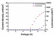
도 2는 본 발명의 다양한 실시예에 따른 화합물을 적용한 녹색 인광 유기발광소자의 전압에 따른 전류 밀도(Current density) 및 휘도(Luminance)에 관한 그래프이다.
도 3은 본 발명의 다양한 실시예에 따른 화합물을 적용한 녹색 인광 유기발광소자의 EL((ElectroLuminescence) 스펙트럼에 관한 그래프이다.
도 4는 본 발명의 다양한 실시예에 따른 화합물을 적용한 녹색 인광 유기발광소자의 시간에 따른 휘도 변화량을 나타낸 그래프이다.
도 5는 본 발명의 다양한 실시예에 따른 화합물을 적용한 청색 인광 유기발광소자의 전압에 따른 전류 밀도(Current density) 및 휘도(Luminance)에 관한 그래프이다.
도 6은 본 발명의 다양한 실시예에 따른 화합물을 적용한 청색 인광 유기발광소자의 EL((ElectroLuminescence) 스펙트럼에 관한 그래프이다.
도 7은 본 발명의 다양한 실시예에 따른 화합물을 적용한 청색 인광 유기발광소자의 시간에 따른 휘도 변화량을 나타낸 그래프이다.1 shows a cross section of an organic light emitting device according to various embodiments.
FIG. 2 is a graph showing current density and luminance according to voltage of a green phosphorescent organic light emitting device to which a compound according to various embodiments of the present invention is applied.
FIG. 3 is a graph of EL ((Electro Luminescence) spectrum of a green phosphorescent organic light emitting device to which a compound according to various embodiments of the present invention is applied.
FIG. 4 is a graph showing a change in luminance over time of a green phosphorescent organic light emitting device to which a compound according to various embodiments of the present invention is applied.
FIG. 5 is a graph of current density and luminance according to voltage of a blue phosphorescent organic light emitting device to which a compound according to various embodiments of the present invention is applied.
FIG. 6 is a graph of EL ((Electro Luminescence) spectrum of a blue phosphorescent organic light emitting device to which a compound according to various embodiments of the present invention is applied.
FIG. 7 is a graph illustrating a change in luminance over time of a blue phosphorescent organic electroluminescent device to which a compound according to various embodiments of the present invention is applied. Referring to FIG.
이하, 본 문서의 다양한 실시예들이 첨부된 도면을 참조하여 기재된다. 실시예 및 이에 사용된 용어들은 본 문서에 기재된 기술을 특정한 실시 형태에 대해 한정하려는 것이 아니며, 해당 실시예의 다양한 변경, 균등물, 및/또는 대체물을 포함하는 것으로 이해되어야 한다.Hereinafter, various embodiments of the present document will be described with reference to the accompanying drawings. It is to be understood that the embodiments and terminologies used herein are not intended to limit the invention to the particular embodiments described, but to include various modifications, equivalents, and / or alternatives of the embodiments.
이하, 첨부한 도면을 참조하여 본 발명의 실시예를 상세하게 설명하면 다음과 같다.Hereinafter, embodiments of the present invention will be described in detail with reference to the accompanying drawings.
본 발명의 다양한 실시예는 하기 화학식 1로 표시되는 화합물에 관한 것이다.Various embodiments of the present invention are directed to compounds represented by the following formula (1).
[화학식 1][Chemical Formula 1]

이때, X는 O 또는 S이고, R1 및 R2는 각각 독립적으로 아릴(aryl), 헤테로아릴(heteroaryl) 및 -P(O)-R3R4 로 이루어진 군에서 선택될 수 있다.Wherein X is O or S, and R1 and R2 are each independently selected from the group consisting of aryl, heteroaryl and -P (O) -R3 R4 .
상기 아릴, 헤테로아릴 및 -P(O)-R3R4 는 (C1-C4)알킬, (C1-C4)알콕시, 아릴 및 헤테로아릴 로 이루어진 군에서 선택된 1개 내지 4개의 치환기로 치환 또는 비치환될 수 있다.Wherein said aryl, heteroaryl and -P (O) -R3 R4 are optionally substituted with 1 to 4 substituents selected from the group consisting of (C1 -C4 ) alkyl, (C1 -C4 ) alkoxy, aryl and heteroaryl ≪ / RTI >
여기서, “아릴”은 6원 내지 10원으로 구성된 기를 의미하고,Here, " aryl " means a group consisting of 6 to 10 members,
“헤테로아릴”은 산소, 황 및 질소(4차 질소 포함)로부터 선택된 1 내지 4개의 헤테로 원자를 갖는 5원 내지 14원으로 구성된 기를 의미하고,&Quot; Heteroaryl " means a group consisting of 5 to 14 members having 1 to 4 heteroatoms selected from oxygen, sulfur and nitrogen (including quaternary nitrogen)
R3 및 R4는 독립적으로 아릴 또는 헤테로아릴로부터 선택될 수 있다.R3 and R4 can be independently selected from aryl or heteroaryl.
구체적으로, 상기 R1 및 R2는 각각 독립적으로 (1)피리딘, (2)피리미딘, (3)페닐피리딘, (4)다이페닐트리아졸, (5)다이피리딜벤젠, (6)페닐테트라진, (7)트리페닐다이아졸, (8)다이페닐포스핀 옥사이드, (9)다이페닐트리아졸, (10)다이페닐옥사졸, (11)다이페닐싸이아졸, (12)페닐옥사다이아졸 및 (13)페닐싸이아다이아졸 로 이루어진 군에서 선택될 수 있다. 이러한 치환기의 화학식은 다음과 같다.Specifically, R1 and R2 are each independently selected from the group consisting of (1) pyridine, (2) pyrimidine, (3) phenylpyridine, (4) diphenyltriazole, Tetrazine, (7) triphenyldiazole, (8) diphenylphosphine oxide, (9) diphenyltriazole, (10) diphenyloxazole, (11) diphenylthiazole, Sol, and (13) phenylthiadiazole. The chemical formula of such a substituent is as follows.
(1) 피리딘(1) Pyridine


(2)피리미딘(2) Pyrimidine

(3)페닐피리딘(3) Phenylpyridine

(4)다이페닐트리아졸(4) diphenyltriazole

(5)다이피리딜벤젠(5) Dipyridylbenzene

(6)페닐테트라진(6) Phenyl tetrazine

(7)트리페닐다이아졸(7) Triphenyldiazole


(8)다이페닐포스핀 옥사이드(8) diphenylphosphine oxide

(9)다이페닐트리아졸(9) diphenyltriazole


(10)다이페닐옥사졸(10) diphenyl oxazole


(11)다이페닐싸이아졸(11) diphenylthiazole


(12)페닐옥사다이아졸(12) Phenyloxadiazole


(13)페닐싸이아다이아졸(13) Phenylthiadiazole


다양한 실시예에 따르면, 상기 화학식 1로 표시되는 화합물은 하기 화학식 2로 표시되는 화합물을 포함할 수 있다.According to various embodiments, the compound represented by Formula 1 may include a compound represented by Formula 2 below.
[화학식 2](2)

즉, 다양한 실시예에 따른 화합물은, X가 O이고, R1 및 R2는 아릴이며, 상기 아릴이 헤테로아릴로 치환된 구조일 수 있다. 또는, 다양한 실시예에 따른 화합물은, 디벤조퓨란(dibenzofuran)의 2번, 6번 위치가 다이피리딜벤젠으로 치환되는 구조를 가질 수 있다.That is, the compounds according to various embodiments may have a structure wherein X is O, R1 and R2 are aryl, and the aryl is substituted with heteroaryl. Alternatively, the compounds according to various embodiments may have a structure in which
다양한 실시예에 따르면, 상기 화학식 1로 표시되는 화합물은 하기 화학식 3으로 표시되는 화합물을 포함할 수 있다.According to various embodiments, the compound represented by Formula 1 may include a compound represented by Formula 3 below.
[화학식 3](3)

즉, 다양한 실시예에 따른 화합물은, X가 O이고, R1 및 R2는 헤테로아릴이며, 상기 헤테로아릴이 비치환된 구조 또는 아릴로 치환된 구조일 수 있다. 또는, 다양한 실시예에 따른 화합물은, 디벤조퓨란의 2번 위치가 피리딘으로 치환되고, 6번 위치가 다이페닐트리아졸로 치환되는 구조를 가질 수 있다.That is, the compounds according to various embodiments are those wherein X is O, R1 and R2 are heteroaryl, and the heteroaryl may be an unsubstituted structure or a structure substituted with aryl. Alternatively, the compounds according to various embodiments may have a structure in which the 2-position of dibenzofurane is substituted with pyridine, and the 6-position is substituted with diphenyltriazole.
한편, 실시예가 이에 한정되는 것은 아니고, 다양한 실시예에 따른 화합물은 디벤조티오펜(dibenzothiophene)의 2, 6번 위치에 다양한 치환기로 치환되는 구조를 가질 수 있다.However, the present invention is not limited thereto, and the compounds according to various embodiments may have a structure in which dibenzothiophene is substituted with various substituents at
다양한 실시예에 따른 화합물을 하기 제조방법을 통해 합성될 수 있다.Compounds according to various embodiments can be synthesized by the following method.
이하, 구체적인 실시예는 다음과 같다.Hereinafter, specific embodiments will be described.
실시예 1: 화학식 2의 화합물의 합성Example 1 Synthesis of Compound (2)
상기 화학식 2의 화합물을 하기 단계를 통해 합성하였다.The compound of
단계 1: 중간체 생성물(화합물 3-A)의 합성Step 1: Synthesis of intermediate product (Compound 3-A)

4-브로모디벤조퓨란 (2g, 8.1mmol) 및 아이오소벤젠-디아세테이트 (1.3g, 4.0mmol), 아이오딘 (1.03g, 4.0mmol) 을 아세트산무수물 10ml, 아세트산 10ml에 현탁 시킨후 소량의 황산을 첨가하고 질소기류 하에서 36시간 상온 교반하였다. 반응 종료 후 디클로로메탄으로 유기층을 추출하고 위 용액을 무수 황산나트륨으로 건조하였다. 감압 증류 후 핵산으로 컬럼하고 재결정하여 상기 화합물 3-A (1.8g, 수율: 60%) 를 제조하였다.(1.3 g, 4.0 mmol) and iodine (1.03 g, 4.0 mmol) were suspended in acetic anhydride (10 ml) and acetic acid (10 ml), and a small amount of sulfuric acid And the mixture was stirred at room temperature for 36 hours under a nitrogen stream. After completion of the reaction, the organic layer was extracted with dichloromethane, and the resulting solution was dried over anhydrous sodium sulfate. After distillation under reduced pressure, the residue was subjected to column chromatography using a nucleic acid and recrystallized to obtain Compound 3-A (1.8 g, yield: 60%).
1H NMR (400MHz, CDCl3) δ (ppm) = 8.27-8.26 (d, 1H), 7.85-7.83 (dd, 1H), 7.79-7.76 (dd, 1H), 7.66-7.63 (dd, 1H), 7.45-4.42 (d, 1H), 7.27-7.23 (t, 1H)1H NMR (400MHz, CDCl3) 灌 (ppm) = 8.27-8.26 (d, 1H), 7.85-7.83 (dd, 1H), 7.79-7.76 4.42 (d, 1 H), 7.27 - 7.23 (t, 1 H)
단계 2: 중간체 생성물(화합물 3-B)의 합성Step 2: Synthesis of intermediate product (Compound 3-B)

피리딘-3-보로닉에시드 (4.1g, 33.4mmol), 1,3,5-트리브로모벤젠 (5g, 15.9mmol) 및 탄산나트륨 (3.4g, 31.8mmol), 테트라키스(트리페닐포스핀)팔라듐 (0.92g, 0.79mmol) 을 디옥산 50ml, 증류수 25ml에 현탁 시킨 후 질소기류 하에서 12시간 환류 교반하였다. 반응 종료 후 디크롤로메탄으로 유기층을 추출하고 위 용액을 무수 황산나트륨으로 건조하였다. 감압 증류 후 에틸아세테이트로 컬럼하여 상기 화합물 3-B (2g, 수율: 40%) 를 제조하였다.(3.4 g, 31.8 mmol), tetrakis (triphenylphosphine) palladium < RTI ID = 0.0 > (0.92 g, 0.79 mmol) were suspended in 50 ml of dioxane and 25 ml of distilled water, and the mixture was refluxed under stirring in a nitrogen stream for 12 hours. After completion of the reaction, the organic layer was extracted with dichloromethane, and the resulting solution was dried over anhydrous sodium sulfate. After distillation under reduced pressure, the residue was subjected to column chromatography with ethyl acetate to obtain the above compound 3-B (2 g, yield: 40%).
1H NMR (400MHz, CDCl3) δ (ppm) = 8.88-8.87 (d, 2H), 8.67-8.65 (dd, 2H), 7.92-7.89 (dt, 2H), 7.76 (d, 2H), 7.69-7.68 (t, 1H), 7.43-7.40 (dd, 2H)2H), 7.76 (d, 2H), 7.76 (d, 2H), 7.69-7.68 (dd, 2H) t, 1 H), 7.43-7.40 (dd, 2H)
단계 3: 중간체 생성물(화합물 3-C)의 합성Step 3: Synthesis of intermediate product (Compound 3-C)

화합물 3-B (5g, 16.1mmol), 비스(피나콜라토)디보론 (5.3g, 20.9mmol) 및 아세트산칼륨 (4.7g, 48.2mmol), [1,1'-비스(디페닐포스피노)페로센]디클로로팔라듐디클로로메탄 (0.66g, 0.80mmol) 을 디옥산 100ml에 현탁 시킨 후 질소기류 하에서 12시간 환류 교반하였다. 반응 종료 후 상기 반응액에서 디클로로메탄으로 유기층을 추출하고 위 용액을 무수 황산나트륨으로 건조하였다. 감압 증류 후 에틸아세테이트로 컬럼하여 상기 화합물 3-C (4.7g, 수율: 82%) 를 제조하였다.(5 g, 16.1 mmol), bis (pinacolato) diboron (5.3 g, 20.9 mmol) and potassium acetate (4.7 g, 48.2 mmol) Ferrocene] Dichloropalladium Dichloromethane (0.66 g, 0.80 mmol) was suspended in dioxane (100 ml), and the mixture was refluxed under stirring in a nitrogen stream for 12 hours. After completion of the reaction, the organic layer was extracted with dichloromethane in the reaction solution, and the resulting solution was dried over anhydrous sodium sulfate. After distillation under reduced pressure, the residue was subjected to column chromatography with ethyl acetate to give the above compound 3-C (4.7 g, yield: 82%).
1H NMR (400MHz, CDCl3) δ (ppm) = 8.94-8.93 (dd, 2H), 8.64-8.62 (dd, 2H), 8.07 (d, 2H), 7.99-7.96 (dt, 2H), 7.87-7.86 (t, 1H), 7.41-7.38 (dd, 2H), 1.39 (s, 12H)2H NMR (400 MHz, CDCl3) 灌 (ppm) = 8.94-8.93 (dd, 2H), 8.64-8.62 (dd, 2H), 8.07 (d, 2H), 7.99-7.96 t, 1 H), 7.41-7.38 (dd, 2H), 1.39 (s, 12H)
단계 4: 최종 생성물(화학식 2의 화합물)의 합성Step 4: Synthesis of the final product (compound of formula 2)

화합물 3-A (2g, 5.4mmol), 화합물 3-C (4.4g, 12.3mmol) 및 인산칼륨 (3.4g, 16.1mmol), 트리스(디벤질리딘아세톤)디팔라듐 (0.25g, 0.27mmol), SPhos (0.22g, 0.54mmol) 을 디옥산 100ml, 증류수 50ml에 현탁 시킨 후 질소기류 하에서 24시간 환류 교반하였다. 반응 종료 후 상기 반응액에서 디클로로메탄으로 유기층을 추출하고 위 용액을 무수 황산나트륨으로 건조하였다. 감압 증류 후 메탄올:디클로로메탄=1:19로 컬럼하여 상기 화합물 3 (1g, 30%) 을 제조하였다.A mixture of compound 3-A (2 g, 5.4 mmol), compound 3-C (4.4 g, 12.3 mmol) and potassium phosphate (3.4 g, 16.1 mmol), tris (dibenzylidineacetone) dipalladium (0.25 g, 0.27 mmol) SPhos (0.22 g, 0.54 mmol) was suspended in dioxane (100 ml) and distilled water (50 ml), and the mixture was stirred under reflux for 24 hours under a nitrogen stream. After completion of the reaction, the organic layer was extracted with dichloromethane in the reaction solution, and the resulting solution was dried over anhydrous sodium sulfate. After distillation under reduced pressure, the residue was subjected to column chromatography using methanol: dichloromethane = 1: 19 to prepare the compound 3 (1 g, 30%).
1H NMR (400MHz, CDCl3) δ (ppm) = 9.04-9.03 (dd, 2H), 9.01-9.00 (dd, 2H), 8.69-8.67 (m, 4H), 8.31-8.30 (d, 1H), 8.17-8.16 (d, 2H), 8.10-8.08 (dd, 1H), 8.07-8.02 (m, 4H), 7.93-7.92 (d, 2H), 7.85-7.84 (t, 1H), 7.84-7.81 (dd, 1H), 7.78-7.77 (t, 1H), 7.76-7.72 (m, 2H), 7.56-7.52 (t, 1H), 7.48-7.43 (m, 4H)1H NMR (400MHz, CDCl3)? (Ppm) = 9.04-9.03 (dd, 2H), 9.01-9.00 (dd, 2H), 8.69-8.67 (m, 4H), 8.31-8.30 2H), 7.85-7.84 (t, 1H), 7.84-7.81 (dd, 1H), 8.16 (d, 2H), 8.10-8.08 ), 7.78-7.77 (t, 1H), 7.76-7.72 (m, 2H), 7.56-7.52 (t, 1H), 7.48-7.43
비교예 1Comparative Example 1
TmPyPB로, 하기와 같은 화학식을 갖는 화합물.TmPyPB, < / RTI >

비교예 2Comparative Example 2
TPBI로, 하기와 같은 화학식을 갖는 화합물With TPBI, a compound having the following formula

하기 표 1은 실시예 1에 따라 합성된 화합물, 비교예 1 및 비교예2의 물리적 특성을 비교한 표이다.Table 1 below is a table comparing the physical properties of the compounds synthesized according to Example 1, Comparative Example 1 and Comparative Example 2.
(화학식 2의 화합물)The compound synthesized according to Example 1
(2)
표 1에 따르면, 실시예 1에 따라 합성된 화합물의 유리전이온도(Tg)는 134 ℃로 비교예 1 및 비교예2의 유리전이온도에 비해 매우 높은 것으로 나타났다. 또한, 실시예 1에 따라 합성된 화합물의 삼중항에너지(ET)는 비교예 2보다 높고, 비교예 1과 유사한 값을 보였다.According to Table 1, the glass transition temperature (Tg) of the compound synthesized according to Example 1 was 134 캜, which was much higher than the glass transition temperature of Comparative Example 1 and Comparative Example 2. The triplet energies (ET ) of the compounds synthesized according to Example 1 were higher than those of Comparative Example 2, showing similar values to those of Comparative Example 1.
따라서, 실시예 1에 따라 합성된 화합물은 높은 유리전이온도를 통해 열적 안정성을 가질 수 있다. 또한, 실시예 1에 따라 합성된 화합물을 유기발광소자의 유기박막층에 적용했을 때, 높은 삼중항에너지를 통해 고효율 및 장수명의 유기발광소자를 확보할 수 있다.Thus, the compound synthesized according to Example 1 can have thermal stability through a high glass transition temperature. In addition, when the compound synthesized according to Example 1 is applied to the organic thin film layer of the organic light emitting device, high efficiency and long-life organic light emitting device can be obtained through high triplet energy.
실시예 2: 화학식 3의 화합물의 합성Example 2: Synthesis of Compound (3)
상기 화학식 3의 화합물을 하기 단계를 통해 합성하였다.The compound of Formula 3 was synthesized by the following procedure.
단계 1: 중간체 생성물(화합물 4-A)의 합성Step 1: Synthesis of intermediate product (Compound 4-A)

화합물 3-A (5g, 13.4mmol), 비스(피나콜라토)디보론 (4.1g, 16.1mmol) 및 아세트산칼륨 (3.95g, 40.2mmol), [1,1'-비스(디페닐포스피노)페로센]디클로로팔라듐디클로로메탄 (0.55g, 0.67mmol) 을 디옥산 150ml에 현탁 시킨 후 질소기류 하에서 12시간 환류 교반하였다. 반응 종료 후 상기 반응액에서 디클로로메탄으로 유기층을 추출하고 위 용액을 무수 황산나트륨으로 건조하였다. 감압 증류 후 핵산:디클로로메탄=4:1로 컬럼하여 상기 화합물 4-A (3g, 수율: 60%) 를 제조하였다.A mixture of compound 3-A (5 g, 13.4 mmol), bis (pinacolato) diboron (4.1 g, 16.1 mmol) and potassium acetate (3.95 g, 40.2 mmol), [1,1'-bis (diphenylphosphino) Ferrocene] Dichloropalladium Dichloromethane (0.55 g, 0.67 mmol) was suspended in dioxane (150 ml), which was stirred under reflux for 12 hours under a stream of nitrogen. After completion of the reaction, the organic layer was extracted with dichloromethane in the reaction solution, and the resulting solution was dried over anhydrous sodium sulfate. After distillation under reduced pressure, the resulting product was subjected to column chromatography using 4: 1 dichloromethane to prepare the above compound 4-A (3 g, yield: 60%).
1H NMR (400MHz, CDCl3) δ (ppm) = 8.43 (s, 1H), 7.98-7.95 (dd, 1H), 7.91-7.89 (dd, 1H), 7.66-7.64 (dd, 1H), 7.62-7.60 (dd, 1H), 7.25-7.21 (t, 1H), 1.40 (s, 12H)1H NMR (400MHz, CDCl3)? (Ppm) = 8.43 (s, IH), 7.98-7.95 (dd, IH), 7.91-7.89 (dd, IH), 7.66-7.64 dd, 1 H), 7.25-7.21 (t, 1 H), 1.40 (s, 12 H)
단계 2: 중간체 생성물(화합물 4-B)의 합성Step 2: Synthesis of intermediate product (Compound 4-B)

마그네슘 (2.57g, 105.7mmol) 과 아이오딘 (0.54g, 2.1mmol)을 테트라하이드로퓨란 30ml에 넣고 교반하였다. 위 용액에 브로모벤젠 (11.1g, 70.5mmol) 이 테트라하이드로퓨란 30ml에 용해된 용액을 천천히 적하하고 2시간 환류 교반하였다.Magnesium (2.57 g, 105.7 mmol) and iodine (0.54 g, 2.1 mmol) were added to 30 ml of tetrahydrofuran and stirred. A solution of bromobenzene (11.1 g, 70.5 mmol) in 30 ml of tetrahydrofuran was slowly added dropwise to the above solution, and the mixture was refluxed with stirring for 2 hours.
위 용액을 1,3,5-트리클로로트리아진 (5g, 27.1mmol) 이 테트라하이드로퓨란 30ml에 용해된 용액을 천천히 0℃ 에서 적하하고 12시간 환류 교반하였다. 반응 종료 후 상기 반응액에서 디클로로메탄으로 유기층을 추출하고 위 용액을 무수 황산나트륨으로 건조하였다. 감압 증류 후 핵산:디클로로메탄=4:1로 컬럼하여 상기 화합물 4-B (4g, 수율: 55%) 를 제조하였다.A solution prepared by dissolving 1,3,5-trichlorotriazine (5 g, 27.1 mmol) in 30 ml of tetrahydrofuran was slowly added dropwise at 0 ° C and refluxed for 12 hours. After completion of the reaction, the organic layer was extracted with dichloromethane in the reaction solution, and the resulting solution was dried over anhydrous sodium sulfate. After distillation under reduced pressure, the resulting product was subjected to column chromatography using 4: 1 dichloromethane to obtain 4-B (4 g, yield: 55%).
1H NMR (400MHz, CDCl3) δ (ppm) = 8.65-8.62 (m, 4H), 7.66-7.62 (m, 2H), 7.58-7.54 (m, 4H)1H NMR (400MHz, CDCl3)? (Ppm) = 8.65-8.62 (m, 4H), 7.66-7.62 (m, 2H), 7.58-7.54
단계 3: 중간체 생성물(화합물 4-C)의 합성Step 3: Synthesis of intermediate product (Compound 4-C)

화합물 4-A (4g, 10.7mmol), 화합물 4-B (3.4g, 12.9mmol) 및 탄산나트륨 (2.3g, 21.4mmol), 테트라키스(트리페닐포스핀)팔라듐 (0.62g, 0.54mmol) 을 디옥산 100ml, 증류수 50ml에 현탁 시킨 후 질소기류 하에서 12시간 환류 교반하였다. 반응 종료 후 상기반응액에서 클로로포름으로 유기층을 추출하고 위 용액을 무수 황산나트륨으로 건조하였다. 감압 증류 후 핵산으로 재결정하여 상기 화합물 4-C (3g, 수율: 58%) 를 제조하였다.(3.4 g, 12.9 mmol) and sodium carbonate (2.3 g, 21.4 mmol) and tetrakis (triphenylphosphine) palladium (0.62 g, 0.54 mmol) Was suspended in 100 ml of oxalic acid and 50 ml of distilled water, and the mixture was refluxed under stirring in a nitrogen stream for 12 hours. After completion of the reaction, the organic layer was extracted with chloroform in the reaction solution, and the resulting solution was dried over anhydrous sodium sulfate. After distillation under reduced pressure, the residue was recrystallized from a nucleic acid to obtain the above compound 4-C (3 g, yield: 58%).
1H NMR (400MHz, CDCl3) δ (ppm) = 9.35 (dd, 1H), 9.00-8.98 (dd, 1H), 8.82-8.79 (m, 4H), 8.11-8.09 (dd, 1H), 7.83-7.80 (dd, 1H), 7.69-7.67 (dd, 1H), 7.64-7.58 (m, 6H), 7.33-7.30 (t, 1H)(Dd, 1H), 8.00-8.98 (dd, 1H), 8.82-8.79 (m, 4H), 8.11-8.09 (dd, 1H), 7.83-7.80 (d, 1H), 7.69-7.67 (dd, 1H), 7.64-7.58 (m, 6H), 7.33-7.30
단계 4: 최종 생성물(화학식 3의 화합물)의 합성Step 4: Synthesis of the final product (compound of formula 3)

화합물 4-C (3g, 6.3mmol), 피리딘-3-보로닉에시드 (0.93g, 7.5mmol) 및 인산칼륨 (4.0g, 18.8mmol), 트리스(디벤질리딘아세톤)디팔라듐 (0.29g, 0.31mmol), SPhos (0.26g, 0.63mmol) 을 디옥산 100ml, 증류수 50ml에 현탁 시킨 후 질소기류 하에서 36시간 환류 교반하였다. 반응 종료 후 상기반응액에서 클로로포름으로 유기층을 추출하고 위 용액을 무수 황산나트륨으로 건조하였다. 감압 증류 후 핵산:에틸아세테이트=1:1로 컬럼하여 상기 화합물 4 (1.5g, 수율: 50%) 를 제조하였다.(0.93 g, 7.5 mmol) and potassium phosphate (4.0 g, 18.8 mmol) and tris (dibenzylidineacetone) dipalladium (0.29 g, 0.31 mmol) in a mixture of 4-C (3 g, 6.3 mmol), pyridine- mmol) and SPhos (0.26 g, 0.63 mmol) were suspended in dioxane (100 ml) and distilled water (50 ml), and the mixture was refluxed under nitrogen stream for 36 hours. After completion of the reaction, the organic layer was extracted with chloroform in the reaction solution, and the resulting solution was dried over anhydrous sodium sulfate. After distillation under reduced pressure, the residue was subjected to column chromatography using nucleic acid: ethyl acetate = 1: 1 to prepare the compound 4 (1.5 g, yield: 50%).
1H NMR (400MHz, CDCl3) δ (ppm) = 9.41 (d, 1H), 9.18 (d 1H), 9.00-8.97 (dd, 1H), 8.83-8.81 (m, 4H), 8.71- 8.69 (1H), 8.28-8.25 (dt, 1H), 8.21-8.19 (dd, 1H), 7.77-7.75 (d, 1H), 7.68-7.66 (dd, 1H), 7.65-7.59 (m, 6H), 7.57-7.53 (t, 1H), 7.51-7.48 (dd, 1H)(D, 1H), 8.83-8.81 (m, 4H), 8.71-8. 69 (1H), (Dd, IH), 8.21-8.19 (dd, IH), 7.77-7.75 (d, IH), 7.68-7.66 (dd, IH), 7.65-7.59 (m, 6H), 7.57-7.53 , ≪ / RTI > 1H), 7.51-7.48 (dd, 1H)
다양한 실시예에 따른 화합물은 유기발광소자의 유기박막층 재료로 사용될 수 있다. 이하, 도 1을 참조하여, 유기발광소자를 설명한다.The compound according to various embodiments can be used as an organic thin film layer material of an organic light emitting device. Hereinafter, an organic light emitting device will be described with reference to FIG.
도 1은 다양한 실시예에 따른 유기발광소자의 단면을 도시한다.1 shows a cross section of an organic light emitting device according to various embodiments.
도 1에 도시된 바와 같이, 유기발광소자는 기판(Substrate)(100), 기판(100) 상에 배치되는 애노드 전극(Anode)(200), 유기박막층(400) 및 캐소드 전극(Cathode)(300)을 포함할 수 있다. 유기발광소자는 인광 유기발광소자 또는 형광 유기발광소자일 수 있다.1, an organic light emitting device includes a
유기박막층(400)은 정공주입층(Hole Injection layer, HIL)(410), 정공수송층(Hole Transport Layer, HTL)(420), 발광층(Emission Layer, EML)(430), 정공저지층(Hole Blocking Layer, HBL)(440) 및 전자수송층(Electron Transport Layer, ETL)(450) 등을 포함할 수 있다. 한편, 도면에 도시하지 않았으나, 유기박막층(400)은 전자주입층(Electron Injection Layer, EIL) 및 전자억제층(Electron Blocking Layer, EBL)을 더 포함할 수 있다. 또한, 다양한 실시예에 따르면, 정공저지층(440)은 정공저지 역할 및 전자수송 역할을 동시에 수행할 수 있다.The organic
애노드 전극(200) 및 캐소드 전극(300)은 금속, 금속산화물 또는 도전성 폴리머로 형성될 수 있다.The
유기박막층(400) 중 적어도 어느 한 층은 앞서 설명한 화학식 1의 화합물을 포함할 수 있다. 바람직하게는, 전자수송층(450) 또는 정공저지층(440)은 화학식 1의 화합물을 포함할 수 있다. 유기발광소자의 전자수송층(450) 또는 정공저지층(440)에 화학식 1의 화합물을 적용할 경우, 높은 삼중항에너지 및 전자이동도를 확보할 수 있고, 정공저지 및 전자주입의 용이성을 가질 수 있으며 열적안정성을 최적화할 수 있다.At least one layer of the organic
도 2는 본 발명의 다양한 실시예에 따른 화합물을 정공저지층(440)에 적용한 녹색 인광 유기발광소자의 전압에 따른 전류 밀도(Current density) 및 휘도(Luminance)에 관한 그래프이다. 다양한 실시예에 따르면, 정공저지층(440)은 정공저지 역할 및 전자수송 역할을 동시에 수행할 수 있다. 다양한 실시예에 따른 화합물을 정공저지층(440)에 적용한 녹색 인광 유기발광소자에서, 전자수송층(450)은 TPBi 물질을 사용하였다.FIG. 2 is a graph showing current density and luminance according to voltage of a green phosphorescent organic light emitting device in which a compound according to various embodiments of the present invention is applied to a
하기 표 2는 본 발명의 다양한 실시예에 따른 화합물을 정공저지층(440)에 적용한 녹색 인광 유기발광소자의 다양한 특성값에 대한 것이다.Table 2 below is for various characteristic values of a green phosphorescent organic light emitting device in which a compound according to various embodiments of the present invention is applied to a
(V)(V)
(mA/(mA /cmcm22))
(%)(%)
(lm/W)(lm / W)
(Cd/A)(Cd / A)
도 2 및 표 2에 따르면, 녹색 인광 유기발광소자의 정공저지층(440)에 본 발명의 다양한 실시예에 따른 화합물을 적용한 경우, 구동 전압이 7.7 V일 때, 전류 밀도가 3.6 mA/cm2로 매우 높은 값을 보여 저전압에서 구동 가능함을 확인할 수 있다. 또한, 구동 전압이 7.7 V일 때, 1002.9 cd/m2의 높은 휘도 값을 보였다. 휘도 1000 cd/m2 기준에서 색좌표는 (0.27, 0.60)이었다. 또한, 휘도 1000 cd/m2 기준에서 양자 효율(Quantum efficiency), 전력 효율(Power efficiency) 및 전류 효율(Current efficiency)이 각각 8.3 %, 11.4 lm/W 및 27.6 Cd/A를 보여 고효율을 가지는 것으로 확인할 수 있었다.2 and Table 2, when the compound according to various embodiments of the present invention is applied to the
도 3은 본 발명의 다양한 실시예에 따른 화합물을 정공저지층(440)에 적용한 녹색 인광 유기발광소자의 EL(ElectroLuminescence) 스펙트럼에 관한 그래프이다. EL 스펙트럼은 유기발광소자로 나오는 빛을 휘도계로 측정하여 나타낸 스펙트럼이다.FIG. 3 is a graph showing EL (Electro Luminescence) spectra of a green phosphorescent organic light emitting device in which a compound according to various embodiments of the present invention is applied to a
도 3에 도시된 바와 같이, 녹색 인광 유기발광소자의 정공저지층(440)에 본 발명의 다양한 실시예에 따른 화합물을 적용한 경우, 녹색의 EL 스펙트럼의 피크파장이 500 nm 내지 520 nm이고, 색순도가 향상됨을 알 수 있다.3, when the compound according to various embodiments of the present invention is applied to the
도 4는 본 발명의 다양한 실시예에 따른 화합물을 정공저지층(440)에 적용한 녹색 인광 유기발광소자의 시간에 따른 휘도 변화량을 나타낸 그래프이다.FIG. 4 is a graph showing a change in luminance over time of a green phosphorescent organic light emitting device in which a compound according to various embodiments of the present invention is applied to a
도 4에 도시된 바와 같이, 본 발명의 다양한 실시예에 따른 화합물을 적용한 녹색 인광 유기발광소자의 경우 시간에 따른 휘도 변화량이 크지 않은 것으로 나타났다. 즉, 장수명의 유기발광소자를 확보할 수 있었다.As shown in FIG. 4, in the case of the green phosphorescent organic electroluminescent device to which the compounds according to various embodiments of the present invention were applied, the change in luminance with time was not large. That is, a long-life organic light emitting element can be secured.
도 5는 본 발명의 다양한 실시예에 따른 화합물을 정공저지층(440)에 적용한 청색 인광 유기발광소자의 전압에 따른 전류 밀도(Current density) 및 휘도(Luminance)에 관한 그래프이다. 다양한 실시예에 따르면, 정공저지층(440)은 정공저지 역할 및 전자수송 역할을 동시에 수행할 수 있다. 다양한 실시예에 따른 화합물을 정공저지층(440)에 적용한 녹색 인광 유기발광소자에서, 전자수송층(450)은 LG 201 물질을 사용하였다.FIG. 5 is a graph showing current density and luminance of a blue phosphorescent organic light emitting device in which a compound according to various embodiments of the present invention is applied to a
하기 표 3은 정공저지층(440)에 본 발명의 다양한 실시예에 따른 화합물을 적용한 청색 인광 유기발광소자의 다양한 특성값에 대한 것이다. 이때, 다양한 특성값은 발광층(430)에 들어가는 도펀트 양을 10 %, 20 % 및 30 %로 조절하여 측정하였다.Table 3 below is for various characteristic values of the blue phosphorescent organic light emitting device to which the compounds according to various embodiments of the present invention are applied to the
(%)(%)
(V)(V)
(mA/(mA /cmcm22))
(%)(%)
(lm/W)(lm / W)
(Cd/A)(Cd / A)
도 5 및 표 3에 따르면, 청색 인광 유기발광소자의 정공저지층(440)에 본 발명의 다양한 실시예에 따른 화합물을 적용한 경우, 발광층(430)에 들어가는 도펀트 양이 30 %이고, 구동 전압이 9.7 V일 때, 전류 밀도가 7. 7 mA/cm2로 매우 높은 값을 보여 저전압에서 구동 가능함을 확인할 수 있다. 또한, 구동 전압이 9.7 V일 때, 1002.2 cd/m2의 높은 휘도 값을 보였다. 휘도 1000 cd/m2 기준에서 색좌표는 (0.15, 0.25)이었다. 또한, 휘도 1000 cd/m2 기준에서 양자 효율(Quantum efficiency), 전력 효율(Power efficiency) 및 전류 효율(Current efficiency)이 각각 7.7 %, 4.2 lm/W 및 13.1 Cd/A를 보여 고효율을 가지는 것으로 확인할 수 있었다.5 and Table 3, when the compound according to various embodiments of the present invention is applied to the
도 6은 본 발명의 다양한 실시예에 따른 화합물을 정공저지층(440)에 적용한 청색 인광 유기발광소자의 EL(ElectroLuminescence) 스펙트럼에 관한 그래프이다.6 is a graph showing EL (Electro Luminescence) spectra of a blue phosphorescent organic light emitting device in which a compound according to various embodiments of the present invention is applied to a
도 6에 도시된 바와 같이, 청색 인광 유기발광소자의 정공저지층(440)에 본 발명의 다양한 실시예에 따른 화합물을 적용한 경우, 청색의 EL 스펙트럼의 피크파장이 450 nm 내지 470 nm이고, 색순도가 향상됨을 알 수 있다.6, when the compound according to various embodiments of the present invention is applied to the
도 7은 본 발명의 다양한 실시예에 따른 화합물을 정공저지층(440)에 적용한 청색 인광 유기발광소자의 시간에 따른 휘도 변화량을 나타낸 그래프이다.7 is a graph showing changes in luminance with time of a blue phosphorescent organic light emitting device in which a compound according to various embodiments of the present invention is applied to a
도 7에 도시된 바와 같이, 본 발명의 다양한 실시예에 따른 화합물을 적용한 청색 인광 유기발광소자의 경우 시간에 따른 휘도 변화량이 크지 않은 것으로 나타났다. 즉, 장수명의 유기발광소자를 확보할 수 있었다.As shown in FIG. 7, in the case of the blue phosphorescent organic electroluminescent device to which the compounds according to various embodiments of the present invention were applied, the change in luminance with time was not large. That is, a long-life organic light emitting element can be secured.
상술한 실시예에 설명된 특징, 구조, 효과 등은 본 발명의 적어도 하나의 실시예에 포함되며, 반드시 하나의 실시예에만 한정되는 것은 아니다. 나아가, 각 실시예에서 예시된 특징, 구조, 효과 등은 실시예들이 속하는 분야의 통상의 지식을 가지는 자에 의하여 다른 실시예들에 대해서도 조합 또는 변형되어 실시 가능하다. 따라서 이러한 조합과 변형에 관계된 내용들은 본 발명의 범위에 포함되는 것으로 해석되어야 할 것이다.The features, structures, effects and the like described in the foregoing embodiments are included in at least one embodiment of the present invention and are not necessarily limited to one embodiment. Further, the features, structures, effects, and the like illustrated in the embodiments may be combined or modified in other embodiments by those skilled in the art to which the embodiments belong. Therefore, it should be understood that the present invention is not limited to these combinations and modifications.
또한, 이상에서 실시예들을 중심으로 설명하였으나 이는 단지 예시일 뿐 본 발명을 한정하는 것이 아니며, 본 발명이 속하는 분야의 통상의 지식을 가진 자라면 본 실시예의 본질적인 특성을 벗어나지 않는 범위에서 이상에 예시되지 않은 여러 가지의 변형과 응용이 가능함을 알 수 있을 것이다. 예를 들어, 실시예들에 구체적으로 나타난 각 구성 요소는 변형하여 실시할 수 있는 것이다. 그리고 이러한 변형과 응용에 관계된 차이점들은 첨부한 청구 범위에서 규정하는 본 발명의 범위에 포함되는 것으로 해석되어야 할 것이다.While the present invention has been particularly shown and described with reference to exemplary embodiments thereof, it is clearly understood that the same is by way of illustration and example only and is not to be construed as limiting the scope of the present invention. It can be seen that various modifications and applications are possible. For example, each component specifically shown in the embodiments may be modified and implemented. It is to be understood that the present invention may be embodied in many other specific forms without departing from the spirit or essential characteristics thereof.
Claims (8)
Translated fromKorean[화학식 1]

상기 화학식 1에서,
X는 O 이고,
R1 및 R2는 헤테로아릴로 치환된 아릴 또는, 비치환 또는 아릴로 치환된 헤테로아릴이고,
여기서,
“아릴”은 6원 내지 10원으로 구성된 기를 의미하고,
“헤테로아릴”은 산소, 황 및 질소(4차 질소 포함)로부터 선택된 1 내지 4개의 헤테로 원자를 갖는 5원 내지 14원으로 구성된 기를 의미하고,
R3 및 R4는 독립적으로 아릴 또는 헤테로아릴로부터 선택된다.
A compound represented by the following formula (1):
[Chemical Formula 1]
In Formula 1,
X is O,
R1 and R2 are aryl substituted with heteroaryl or heteroaryl substituted with unsubstituted or aryl,
here,
&Quot; Aryl " means a group consisting of 6 to 10 members,
&Quot; Heteroaryl " means a group consisting of 5 to 14 members having 1 to 4 heteroatoms selected from oxygen, sulfur and nitrogen (including quaternary nitrogen)
R3 and R4 are independently selected from aryl or heteroaryl.
상기 R1 및 R2는 각각 독립적으로 피리딘, 피리미딘, 페닐피리딘, 다이페닐트리아졸, 다이피리딜벤젠, 페닐테트라진, 트리페닐다이아졸, 다이페닐트리아졸, 다이페닐옥사졸, 다이페닐싸이아졸, 페닐옥사다이아졸 및 페닐싸이아다이아졸 로 이루어진 군에서 선택되는 화합물.
The method according to claim 1,
Wherein R1 and R2 are each independently selected from the group consisting of pyridine, pyrimidine, phenylpyridine, diphenyltriazole, dipyridylbenzene, phenyltetrazine, triphenyldiazole, diphenyltriazole, diphenyloxazole, Azole, phenyloxadiazole, and phenylthiadiazole.
상기 화합물은 하기 화학식 2로 표시되는 화합물을 포함한다:
[화학식 2]

The method according to claim 1,
The compound includes a compound represented by the following formula (2): < EMI ID =
(2)
상기 화합물은 하기 화학식 3으로 표시되는 화합물을 포함한다:
[화학식 3]

The method according to claim 1,
The compound includes a compound represented by the following Formula 3:
(3)
[화학식 4]

피리딘-3-보로닉에시드, 1,3,5-트리브로모벤젠, 탄산나트륨 및 테트라키스(트리페닐포스핀)팔라듐을 반응시켜 하기 화학식 5의 화합물을 합성하는 과정;
[화학식 5]

상기 화학식 5의 화합물, 비스(피나콜라토)디보론, 아세트산칼륨 및 [1,1'-비스(디페닐포스피노)페로센]디클로로팔라듐디클로로메탄을 반응시켜 하기 화학식 6의 화합물을 합성하는 과정; 및
[화학식 6]

상기 화학식 4의 화합물, 상기 화학식 6의 화합물, 인산칼륨, 트리스(디벤질리딘아세톤)디팔라듐 및 SPhos을 반응시켜 하기 화학식 2의 화합물을 합성하는 과정을 포함하는 화합물의 제조방법.
[화학식 2]

4-bromodibenzofuran, iodobenzene-diacetate, and iodine, to synthesize a compound of Formula 4;
[Chemical Formula 4]
Pyridine-3-boronic acid, 1,3,5-tribromobenzene, sodium carbonate, and tetrakis (triphenylphosphine) palladium;
[Chemical Formula 5]
A step of synthesizing a compound of Formula 6 by reacting the compound of Formula 5, bis (pinacolato) diboron, potassium acetate and [1,1'-bis (diphenylphosphino) ferrocene] dichloropalladium dichloromethane; And
[Chemical Formula 6]
And reacting the compound of Formula 4, the compound of Formula 6, potassium phosphate, tris (dibenzylidineacetone) dipalladium, and SPhos to synthesize a compound of Formula 2 below.
(2)
[화학식 4]

상기 화학식 4의 화합물, 비스(피나콜라토)디보론, 아세트산칼륨 및 [1,1'-비스(디페닐포스피노)페로센]디클로로팔라듐디클로로메탄을 반응시켜 하기 화학식 7의 화합물을 합성하는 과정;
[화학식 7]

마그네슘, 아이오딘, 테트라하이드로퓨란 및 브로모벤젠을 반응시켜 하기 화학식 8의 화합물을 합성하는 과정;
[화학식 8]

상기 화학식 7의 화합물, 상기 화학식 8의 화합물, 탄산나트륨 및 테트라키스(트리페닐포스핀)팔라듐을 반응시켜 하기 화학식 9의 화합물을 합성하는 과정; 및
[화학식 9]

상기 화학식 9의 화합물, 피리딘-3-보로닉에시드, 인산칼륨, 트리스(디벤질리딘아세톤)디팔라듐 및 SPhos을 반응시켜 하기 화학식 3의 화합물을 합성하는 과정을 포함하는 화합물의 제조방법.
[화학식 3]

4-bromodibenzofuran, iodobenzene-diacetate, and iodine, to synthesize a compound of Formula 4;
[Chemical Formula 4]
Reacting a compound of Formula 4, bis (pinacolato) diboron, potassium acetate and [1,1'-bis (diphenylphosphino) ferrocene] dichloropalladium dichloromethane to synthesize a compound of Formula 7;
(7)
Magnesium, iodine, tetrahydrofuran and bromobenzene to synthesize a compound of formula (8);
[Chemical Formula 8]
Reacting the compound of Formula 7, the compound of Formula 8, sodium carbonate and tetrakis (triphenylphosphine) palladium to synthesize a compound of Formula 9; And
[Chemical Formula 9]
And reacting the compound of Formula 9, pyridine-3-boronic acid, potassium phosphate, tris (dibenzylidineacetone) dipalladium and SPhos to synthesize a compound of Formula 3 below.
(3)
캐소드 전극 및
상기 애노드 전극과 캐소드 전극 사이에 개재되는 한 층 이상의 유기박막층을 포함하고,
상기 유기박막층 중 적어도 어느 한 층은 제1항 내지 제4항 중 적어도 어느 한 항에 따른 화합물을 포함하는 유기발광소자.An anode electrode;
The cathode electrode and
And at least one organic thin film layer interposed between the anode electrode and the cathode electrode,
Wherein at least one of the organic thin film layers comprises a compound according to any one of claims 1 to 4.
상기 유기박막층은 정공주입층(HIL), 정공수송층(HTL), 정공저지층(HBL), 전자수송층(ETL), 및 전자주입층(EIL)으로 이루어진 군에서 선택된 하나 이상의 것을 더욱 포함하는 것을 특징으로 하는 유기발광소자.8. The method of claim 7,
The organic thin film layer may further include at least one selected from the group consisting of a hole injection layer (HIL), a hole transport layer (HTL), a hole blocking layer (HBL), an electron transport layer (ETL) .
Priority Applications (4)
| Application Number | Priority Date | Filing Date | Title |
|---|---|---|---|
| KR1020170014073AKR101935778B1 (en) | 2017-01-31 | 2017-01-31 | Compound, manufacturing methode of the same and an organic light emitting device comprising the same |
| US16/482,596US11345688B2 (en) | 2017-01-31 | 2018-01-22 | Compound, preparing method therefor, and organic light emitting element comprising same |
| CN201880009412.8ACN110234644B (en) | 2017-01-31 | 2018-01-22 | Compound, preparation method of compound, and organic light emitting device including compound |
| PCT/KR2018/000939WO2018143591A2 (en) | 2017-01-31 | 2018-01-22 | Compound, preparing method therefor, and organic light emitting element comprising same |
Applications Claiming Priority (1)
| Application Number | Priority Date | Filing Date | Title |
|---|---|---|---|
| KR1020170014073AKR101935778B1 (en) | 2017-01-31 | 2017-01-31 | Compound, manufacturing methode of the same and an organic light emitting device comprising the same |
Publications (2)
| Publication Number | Publication Date |
|---|---|
| KR20180089222A KR20180089222A (en) | 2018-08-08 |
| KR101935778B1true KR101935778B1 (en) | 2019-01-07 |
Family
ID=63039916
Family Applications (1)
| Application Number | Title | Priority Date | Filing Date |
|---|---|---|---|
| KR1020170014073AActiveKR101935778B1 (en) | 2017-01-31 | 2017-01-31 | Compound, manufacturing methode of the same and an organic light emitting device comprising the same |
Country Status (4)
| Country | Link |
|---|---|
| US (1) | US11345688B2 (en) |
| KR (1) | KR101935778B1 (en) |
| CN (1) | CN110234644B (en) |
| WO (1) | WO2018143591A2 (en) |
Families Citing this family (1)
| Publication number | Priority date | Publication date | Assignee | Title |
|---|---|---|---|---|
| KR102768535B1 (en)* | 2023-09-27 | 2025-02-18 | 덕산네오룩스 주식회사 | Compound for organic electronic element, organic electronic element using the same, and an electronic device thereof |
Family Cites Families (6)
| Publication number | Priority date | Publication date | Assignee | Title |
|---|---|---|---|---|
| WO2011157790A1 (en)* | 2010-06-18 | 2011-12-22 | Basf Se | Organic electronic devices comprising a layer of a dibenzofurane compound and a 8-hydroxyquinolinolato earth alkaline metal, or alkali metal complex |
| US10297762B2 (en)* | 2014-07-09 | 2019-05-21 | Universal Display Corporation | Organic electroluminescent materials and devices |
| US11495749B2 (en) | 2015-04-06 | 2022-11-08 | Universal Display Corporation | Organic electroluminescent materials and devices |
| KR101694496B1 (en) | 2015-06-03 | 2017-01-11 | (주)위델소재 | Dibenzothiophene derivative compound and organic electroluminescent device using the same |
| KR102523099B1 (en)* | 2015-06-18 | 2023-04-18 | 엘지디스플레이 주식회사 | Organic light emitting device |
| KR101722404B1 (en)* | 2015-08-31 | 2017-04-03 | 주식회사 포스코 | Transfer car preventing weight measurement error and method of controlling the same |
- 2017
- 2017-01-31KRKR1020170014073Apatent/KR101935778B1/enactiveActive
- 2018
- 2018-01-22WOPCT/KR2018/000939patent/WO2018143591A2/ennot_activeCeased
- 2018-01-22USUS16/482,596patent/US11345688B2/enactiveActive
- 2018-01-22CNCN201880009412.8Apatent/CN110234644B/enactiveActive
Also Published As
| Publication number | Publication date |
|---|---|
| KR20180089222A (en) | 2018-08-08 |
| WO2018143591A3 (en) | 2018-12-06 |
| CN110234644A (en) | 2019-09-13 |
| US20190359602A1 (en) | 2019-11-28 |
| US11345688B2 (en) | 2022-05-31 |
| CN110234644B (en) | 2022-10-11 |
| WO2018143591A2 (en) | 2018-08-09 |
Similar Documents
| Publication | Publication Date | Title |
|---|---|---|
| KR101996649B1 (en) | Pyrene derivative compounds and organic light-emitting diode including the same | |
| US8048542B2 (en) | Bis-phenanthroimidazolyl compound and electroluminescent device using the same | |
| KR101861263B1 (en) | Anthracene deriva tives and organic light-emitting diode including the same | |
| KR102169273B1 (en) | Organic electroluminescent compound comprising acridine derivative and organic electroluminescent device comprising same | |
| KR102017506B1 (en) | Phenanthridine Derivatives and organic light-emitting diode including the same | |
| KR101529878B1 (en) | Organic Light Emitting Material and Organic Light Emitting Diode Having The Same | |
| KR20160088229A (en) | organic light-emitting diode with High efficiency and long lifetime | |
| KR20110041726A (en) | Aromatic Compounds and Organic Electroluminescent Devices Using the Same | |
| KR20130110347A (en) | Indenophenanthrene derivatives and organic light emitting diodes comprising the derivatives | |
| KR20150043669A (en) | Compound for organic electronic element, organic electronic element using the same, and an electronic device thereof | |
| KR20110041728A (en) | Aromatic Compounds and Organic Electroluminescent Devices Using the Same | |
| KR20160075519A (en) | Organic electroluminescent material and organic electroluminescent device | |
| KR102659372B1 (en) | Novel compound and organic electroluminescent device comprising the same | |
| KR102402220B1 (en) | Novel blue fluorescent host compound and organic electroluminescent device comprising same | |
| KR20100116690A (en) | Substituted bipyridyl compound and organic electroluminescent element | |
| KR20150100860A (en) | Material for organic electroluminescent elements and organic electroluminescent elements using same | |
| KR101749943B1 (en) | An organoelectro luminescent compounds and organoelectro luminescent device using the same | |
| KR20150071634A (en) | A material for organic electroluminescent device and an organic electroluminescent device using the same | |
| KR20150144487A (en) | Noble amine compound comprising aromatic amine group and organic light-emitting diode including the same | |
| JP2012167058A (en) | 1,8-aryl-substituted naphthalene derivative exhibiting excimer characteristic, and organic el element obtained by using the same | |
| KR101226701B1 (en) | Aromatic compound and organic electroluminescent device using the same | |
| KR102394948B1 (en) | Heterocyclic composite and organic light emitting device comprising the same | |
| KR101815653B1 (en) | Azaboradibenzochrysene derivatives organic electroluminescent compound, ink composition and organic electroluminescent device | |
| CN105777809B (en) | Electroluminescent organic material and organic electroluminescence device | |
| KR101724303B1 (en) | Pyrene compound and organic electroluminescent devices comprising the same |
Legal Events
| Date | Code | Title | Description |
|---|---|---|---|
| A201 | Request for examination | ||
| PA0109 | Patent application | St.27 status event code:A-0-1-A10-A12-nap-PA0109 | |
| PA0201 | Request for examination | St.27 status event code:A-1-2-D10-D11-exm-PA0201 | |
| P11-X000 | Amendment of application requested | St.27 status event code:A-2-2-P10-P11-nap-X000 | |
| P13-X000 | Application amended | St.27 status event code:A-2-2-P10-P13-nap-X000 | |
| D13-X000 | Search requested | St.27 status event code:A-1-2-D10-D13-srh-X000 | |
| D14-X000 | Search report completed | St.27 status event code:A-1-2-D10-D14-srh-X000 | |
| E902 | Notification of reason for refusal | ||
| PE0902 | Notice of grounds for rejection | St.27 status event code:A-1-2-D10-D21-exm-PE0902 | |
| P11-X000 | Amendment of application requested | St.27 status event code:A-2-2-P10-P11-nap-X000 | |
| P13-X000 | Application amended | St.27 status event code:A-2-2-P10-P13-nap-X000 | |
| PG1501 | Laying open of application | St.27 status event code:A-1-1-Q10-Q12-nap-PG1501 | |
| E90F | Notification of reason for final refusal | ||
| PE0902 | Notice of grounds for rejection | St.27 status event code:A-1-2-D10-D21-exm-PE0902 | |
| P11-X000 | Amendment of application requested | St.27 status event code:A-2-2-P10-P11-nap-X000 | |
| P13-X000 | Application amended | St.27 status event code:A-2-2-P10-P13-nap-X000 | |
| R18-X000 | Changes to party contact information recorded | St.27 status event code:A-3-3-R10-R18-oth-X000 | |
| E701 | Decision to grant or registration of patent right | ||
| PE0701 | Decision of registration | St.27 status event code:A-1-2-D10-D22-exm-PE0701 | |
| GRNT | Written decision to grant | ||
| PR0701 | Registration of establishment | St.27 status event code:A-2-4-F10-F11-exm-PR0701 | |
| PR1002 | Payment of registration fee | St.27 status event code:A-2-2-U10-U11-oth-PR1002 Fee payment year number:1 | |
| PG1601 | Publication of registration | St.27 status event code:A-4-4-Q10-Q13-nap-PG1601 | |
| P14-X000 | Amendment of ip right document requested | St.27 status event code:A-5-5-P10-P14-nap-X000 | |
| R18-X000 | Changes to party contact information recorded | St.27 status event code:A-5-5-R10-R18-oth-X000 | |
| PR1001 | Payment of annual fee | St.27 status event code:A-4-4-U10-U11-oth-PR1001 Fee payment year number:4 | |
| PN2301 | Change of applicant | St.27 status event code:A-5-5-R10-R13-asn-PN2301 St.27 status event code:A-5-5-R10-R11-asn-PN2301 | |
| PR1001 | Payment of annual fee | St.27 status event code:A-4-4-U10-U11-oth-PR1001 Fee payment year number:5 | |
| P22-X000 | Classification modified | St.27 status event code:A-4-4-P10-P22-nap-X000 | |
| P22-X000 | Classification modified | St.27 status event code:A-4-4-P10-P22-nap-X000 | |
| PR1001 | Payment of annual fee | St.27 status event code:A-4-4-U10-U11-oth-PR1001 Fee payment year number:6 | |
| PR1001 | Payment of annual fee | St.27 status event code:A-4-4-U10-U11-oth-PR1001 Fee payment year number:7 | |
| P22-X000 | Classification modified | St.27 status event code:A-4-4-P10-P22-nap-X000 | |
| PR1001 | Payment of annual fee | St.27 status event code:A-4-4-U10-U11-oth-PR1001 Fee payment year number:8 |