KR101932403B1 - Apparatus and method for formation of an energized ophthalmic device for light therapy - Google Patents
Apparatus and method for formation of an energized ophthalmic device for light therapyDownload PDFInfo
- Publication number
- KR101932403B1 KR101932403B1KR1020137023285AKR20137023285AKR101932403B1KR 101932403 B1KR101932403 B1KR 101932403B1KR 1020137023285 AKR1020137023285 AKR 1020137023285AKR 20137023285 AKR20137023285 AKR 20137023285AKR 101932403 B1KR101932403 B1KR 101932403B1
- Authority
- KR
- South Korea
- Prior art keywords
- light
- light source
- lens
- energy source
- ophthalmic lens
- Prior art date
- Legal status (The legal status is an assumption and is not a legal conclusion. Google has not performed a legal analysis and makes no representation as to the accuracy of the status listed.)
- Expired - Fee Related
Links
Images


Classifications
- B—PERFORMING OPERATIONS; TRANSPORTING
- B29—WORKING OF PLASTICS; WORKING OF SUBSTANCES IN A PLASTIC STATE IN GENERAL
- B29D—PRODUCING PARTICULAR ARTICLES FROM PLASTICS OR FROM SUBSTANCES IN A PLASTIC STATE
- B29D11/00—Producing optical elements, e.g. lenses or prisms
- A—HUMAN NECESSITIES
- A61—MEDICAL OR VETERINARY SCIENCE; HYGIENE
- A61N—ELECTROTHERAPY; MAGNETOTHERAPY; RADIATION THERAPY; ULTRASOUND THERAPY
- A61N5/00—Radiation therapy
- A61N5/06—Radiation therapy using light
- A61N5/0613—Apparatus adapted for a specific treatment
- A61N5/0618—Psychological treatment
- A—HUMAN NECESSITIES
- A61—MEDICAL OR VETERINARY SCIENCE; HYGIENE
- A61N—ELECTROTHERAPY; MAGNETOTHERAPY; RADIATION THERAPY; ULTRASOUND THERAPY
- A61N5/00—Radiation therapy
- A61N5/06—Radiation therapy using light
- A—HUMAN NECESSITIES
- A61—MEDICAL OR VETERINARY SCIENCE; HYGIENE
- A61P—SPECIFIC THERAPEUTIC ACTIVITY OF CHEMICAL COMPOUNDS OR MEDICINAL PREPARATIONS
- A61P27/00—Drugs for disorders of the senses
- A61P27/02—Ophthalmic agents
- B—PERFORMING OPERATIONS; TRANSPORTING
- B29—WORKING OF PLASTICS; WORKING OF SUBSTANCES IN A PLASTIC STATE IN GENERAL
- B29D—PRODUCING PARTICULAR ARTICLES FROM PLASTICS OR FROM SUBSTANCES IN A PLASTIC STATE
- B29D11/00—Producing optical elements, e.g. lenses or prisms
- B29D11/00009—Production of simple or compound lenses
- B29D11/00038—Production of contact lenses
- B—PERFORMING OPERATIONS; TRANSPORTING
- B29—WORKING OF PLASTICS; WORKING OF SUBSTANCES IN A PLASTIC STATE IN GENERAL
- B29D—PRODUCING PARTICULAR ARTICLES FROM PLASTICS OR FROM SUBSTANCES IN A PLASTIC STATE
- B29D11/00—Producing optical elements, e.g. lenses or prisms
- B29D11/0074—Production of other optical elements not provided for in B29D11/00009- B29D11/0073
- B29D11/00807—Producing lenses combined with electronics, e.g. chips
- G—PHYSICS
- G02—OPTICS
- G02C—SPECTACLES; SUNGLASSES OR GOGGLES INSOFAR AS THEY HAVE THE SAME FEATURES AS SPECTACLES; CONTACT LENSES
- G02C11/00—Non-optical adjuncts; Attachment thereof
- G02C11/04—Illuminating means
- G—PHYSICS
- G02—OPTICS
- G02C—SPECTACLES; SUNGLASSES OR GOGGLES INSOFAR AS THEY HAVE THE SAME FEATURES AS SPECTACLES; CONTACT LENSES
- G02C7/00—Optical parts
- G02C7/02—Lenses; Lens systems ; Methods of designing lenses
- G02C7/04—Contact lenses for the eyes
- A—HUMAN NECESSITIES
- A61—MEDICAL OR VETERINARY SCIENCE; HYGIENE
- A61N—ELECTROTHERAPY; MAGNETOTHERAPY; RADIATION THERAPY; ULTRASOUND THERAPY
- A61N5/00—Radiation therapy
- A61N5/06—Radiation therapy using light
- A61N2005/0635—Radiation therapy using light characterised by the body area to be irradiated
- A61N2005/0643—Applicators, probes irradiating specific body areas in close proximity
- A61N2005/0645—Applicators worn by the patient
- A61N2005/0647—Applicators worn by the patient the applicator adapted to be worn on the head
- A61N2005/0648—Applicators worn by the patient the applicator adapted to be worn on the head the light being directed to the eyes
- A—HUMAN NECESSITIES
- A61—MEDICAL OR VETERINARY SCIENCE; HYGIENE
- A61N—ELECTROTHERAPY; MAGNETOTHERAPY; RADIATION THERAPY; ULTRASOUND THERAPY
- A61N5/00—Radiation therapy
- A61N5/06—Radiation therapy using light
- A61N2005/065—Light sources therefor
- A61N2005/0651—Diodes
- A61N2005/0652—Arrays of diodes
- A—HUMAN NECESSITIES
- A61—MEDICAL OR VETERINARY SCIENCE; HYGIENE
- A61N—ELECTROTHERAPY; MAGNETOTHERAPY; RADIATION THERAPY; ULTRASOUND THERAPY
- A61N5/00—Radiation therapy
- A61N5/06—Radiation therapy using light
- A61N2005/0658—Radiation therapy using light characterised by the wavelength of light used
- A61N2005/0662—Visible light
- A61N2005/0663—Coloured light
Landscapes
- Health & Medical Sciences (AREA)
- Engineering & Computer Science (AREA)
- Ophthalmology & Optometry (AREA)
- Physics & Mathematics (AREA)
- General Health & Medical Sciences (AREA)
- Biomedical Technology (AREA)
- General Physics & Mathematics (AREA)
- Optics & Photonics (AREA)
- Veterinary Medicine (AREA)
- Public Health (AREA)
- Mechanical Engineering (AREA)
- Animal Behavior & Ethology (AREA)
- Life Sciences & Earth Sciences (AREA)
- Nuclear Medicine, Radiotherapy & Molecular Imaging (AREA)
- Manufacturing & Machinery (AREA)
- Pathology (AREA)
- Radiology & Medical Imaging (AREA)
- Social Psychology (AREA)
- Psychology (AREA)
- Psychiatry (AREA)
- Hospice & Palliative Care (AREA)
- Developmental Disabilities (AREA)
- Child & Adolescent Psychology (AREA)
- Microelectronics & Electronic Packaging (AREA)
- Bioinformatics & Cheminformatics (AREA)
- Chemical & Material Sciences (AREA)
- Chemical Kinetics & Catalysis (AREA)
- General Chemical & Material Sciences (AREA)
- Medicinal Chemistry (AREA)
- Organic Chemistry (AREA)
- Pharmacology & Pharmacy (AREA)
- Eyeglasses (AREA)
- Radiation-Therapy Devices (AREA)
- Materials For Medical Uses (AREA)
- Casting Or Compression Moulding Of Plastics Or The Like (AREA)
Abstract
Translated fromKoreanDescription
Translated fromKorean관련 출원Related application
본 출원은 그 내용이 신뢰되고 참고로 포함된, 2011년 2월 4일자로 출원된 미국 가특허 출원 제61/439,535호; 및 2012년 1월 31일자로 출원된 미국 특허 출원 제13/362,275호에 대해 우선권을 주장한다.This application is related to U.S. Provisional Patent Application No. 61 / 439,535, filed February 4, 2011, the contents of which are incorporated herein by reference; And U.S. Patent Application No. 13 / 362,275, filed January 31, 2012, all of which are incorporated herein by reference.
본 발명은 동력공급형 생의학 장치(energized biomedical device)의 제조를 위한, 그리고 더욱 구체적으로는 일부 실시예에서 광 요법(light therapy)을 위한 동력공급형 안과용 렌즈(energized ophthalmic lens)의 제조를 위한 방법 및 장치를 기술한다.The present invention relates to the production of energized biomedical devices for the production of energized biomedical devices and more particularly to the production of energized ophthalmic lenses for light therapy in some embodiments. Method and apparatus.
계절성 정서 장애(seasonal affective disorder, SAD)는 확립된 기분 장애(mood disorder)로서, 그 환자는 연중 소정의 계절에, 가장 흔하게는 겨울에 해당하는 달들 동안 우울증 증상을 경험한다. SAD에 의해 영향을 받는 사람은 흔히 연중 대부분 동안에는 정상적인 정신 건강 상태에 있다. SAD의 증상은 과도한 수면, 에너지 부족, 탄수화물 중독(craving carbohydrate), 집중력 감소, 및 사회적 활동의 위축을 포함할 수 있지만, 이에 제한되지 않는다. 증상은 우울, 절망, 비관 및 기쁨 부족의 감정을 야기한다.Seasonal affective disorder (SAD) is an established mood disorder in which the patient experiences depressive symptoms during certain seasons of the year, most commonly during the winter months. People affected by SAD are usually in a normal mental state during most of the year. Symptoms of SAD may include, but are not limited to, excessive sleep, lack of energy, craving carbohydrate, decreased concentration, and atrophy of social activity. Symptoms cause feelings of depression, despair, pessimism, and lack of joy.
계절성 기분 변화는 광에 대한 노출의 변화와 관련되는 것으로 여겨진다. 더 적은 일광 시간, 더 낮은 태양광 강도, 또는 상당한 기간의 흐린 하늘을 경험하는 북극 지방과 같은 지리적 지역은 더 큰 SAD 발생 정도를 나타낸다. 성인 인구 중에서의 SAD의 유병률 변화는 미국 내에서 명백한데, 플로리다주 및 다른 햇볕이 잘 드는 주에서의 낮은 비율로부터 알래스카주, 뉴햄프셔주 및 다른 북쪽 또는 흐린 지역에서의 현저하게 높은 비율로 분포한다.Seasonal mood changes are believed to be associated with changes in exposure to light. Geographical areas such as the Arctic region experiencing less sunlight time, lower solar intensity, or a considerable period of cloudy sky indicate a greater degree of SAD occurrence. The prevalence of SAD in the adult population is evident in the United States, at a significantly higher rate in Alaska, New Hampshire and other northern or blurry regions from lower rates in Florida and other sunny states.
광 요법은 전형적인 또는 겨울철 계절성 정서 장애에 대한 탁월하고 효과적인 치료로서 연구되고 확립되어 왔다. 광 요법은 표준 백열 램프보다 상당하게 높은 루멘(lumen)을 방출하는 장치를 채용한다. 통상적인 구현은 10,000 룩스(lux)의 바람직하게 밝은 백색 전 스펙트럼(full spectrum) 광, 또는 선택적으로 2,500 룩스의 480 nm의 파장에서의 청색 광, 또는 350 룩스의 500 nm의 파장에서의 녹색 광을 포함한다. 광 요법은 보통 환자가 매일 30 내지 60분 동안 광원으로부터의 규정된 거리에서 그들의 눈을 뜬 채로 앉아 있을 것을 필요로 한다. 이러한 계절성 치료는 환자가 자연 광에 대한 빈번한 노출을 경험할 때까지 수 주 동안 유지된다. 대부분의 환자는 요법을 불편하게 느끼며, 따라서 상당한 비율, 일부 연구에서는 최대 19%가 치료를 중단한다. 그러므로, 더욱 편리하고, 지속적이며, 지능적 방식으로 광 요법을 전달하기 위한 새로운 방법 및 접근법이 요구된다.Phototherapy has been studied and established as an excellent and effective treatment for typical or winter seasonal affective disorders. Phototherapy employs devices that emit significantly higher lumens than standard incandescent lamps. A typical implementation is to use a preferably bright white full spectrum light of 10,000 lux or alternatively blue light at a wavelength of 480 nm at 2,500 lux or green light at a wavelength of 500 nm at 350 lux . Phototherapy usually requires patients to sit with their eyes open at a prescribed distance from the light source for 30 to 60 minutes each day. This seasonal treatment is maintained for several weeks until the patient experiences frequent exposure to natural light. Most patients feel uncomfortable with the therapy, and thus a significant percentage, in some studies, up to 19% discontinue therapy. Therefore, new methods and approaches for delivering phototherapy in a more convenient, continuous, and intelligent manner are needed.
따라서, 본 발명은 광 요법을 전달하기 위한 동력공급형 부분 및 광원을 구비한, 안과용 렌즈와 같은 생의학 장치를 형성하기 위한 방법 및 장치를 포함한다. 광원을 구비한 동력공급형 안과용 렌즈, 광원을 구비한 동력공급형 안과용 렌즈를 형성하기 위한 장치 및 이를 위한 방법에 대한 개시가 포함된다. 에너지 공급원, 광원, 및 다른 원하는 구성요소가 제1 금형 부분품(mold part) 및 제2 금형 부분품 중 하나 또는 둘 모두의 상으로, 또는 제1 금형 부분품 및 제2 금형 부분품 중 하나 또는 둘 모두의 상으로 침착된 삽입체(insert) 내로 침착될 수 있다. 반응성 단량체 혼합물이 제1 금형 부분품과 제2 금형 부분품 사이에 배치된다. 제1 금형 부분품이 제2 금형 부분품에 근접하게 위치되고 이로써 렌즈 공동(lens cavity)이 형성되어, 에너지 공급원과 광원과 반응성 단량체 혼합물의 적어도 일부가 렌즈 공동 내에 있게 되며; 반응성 단량체 혼합물은 화학 방사선에 노출된다. 렌즈는 반응성 단량체 혼합물이 노출되는 화학 방사선의 제어를 통해 형성된다.Accordingly, the present invention includes a method and apparatus for forming a biomedical device, such as an ophthalmic lens, with a powered part and a light source for delivering phototherapy. A power supply type ophthalmic lens having a light source, an apparatus for forming a power supply type ophthalmic lens having a light source, and a method for the same. The energy source, light source, and other desired components may be disposed on one or both of the first mold part and the second mold part, or on the top of one or both of the first mold part and the second mold part Gt; deposited < / RTI > into the insert. A reactive monomer mixture is disposed between the first mold part and the second mold part. The first mold part is positioned proximate to the second mold part so that a lens cavity is formed such that at least a portion of the energy source and the light source and the reactive monomer mixture are in the lens cavity; The reactive monomer mixture is exposed to actinic radiation. The lens is formed through the control of actinic radiation in which the reactive monomer mixture is exposed.
<도 1>
도 1은 본 발명의 일부 실시예에 따른 금형 조립체 장치를 예시하는 도면.
<도 2>
도 2는 에너지 공급원 및 구성요소가 포함된 안과용 렌즈를 예시하는 도면.
<도 3>
도 3은 에너지 공급원을 안과용 렌즈를 형성하기 위한 금형 부분품에 근접하게 배치하기 위한 장치를 예시하는 도면.
<도 4>
도 4는 본 발명의 일부 실시예에 따른 방법 단계들을 예시하는 도면.
<도 5>
도 5는 본 발명의 일부 추가 태양에 따른 방법 단계들을 예시하는 도면.
<도 6>
도 6은 본 발명의 일부 실시예를 구현하기 위해 사용될 수 있는 프로세서를 예시하는 도면.
<도 7>
도 7은 일부 예시적인 유형의 에너지 공급원을, 이들이 제공할 수 있는 에너지의 양의 추정치를 그들의 체적에 대한 비로서 순서대로 예시하는 도면.
<도 8a 내지 도 8d>
도 8a 내지 도 8d는 에너지 공급원에 대한 예시적인 설계 형상을 예시하는 도면.
<도 9>
도 9는 재동력공급(reenergization)을 위한 장치 및 동력공급형 구성요소를 구비한 동력공급형 안과용 렌즈의 예를 예시하는 도면.
<도 10>
도 10은 본 발명의 일부 실시예에 따른 광원을 포함하는 동력공급형 안과용 렌즈의 단면도.≪ 1 >
BRIEF DESCRIPTION OF THE DRAWINGS Figure 1 illustrates a mold assembly apparatus according to some embodiments of the present invention.
2,
Figure 2 illustrates an ophthalmic lens that includes an energy source and components.
3,
Figure 3 illustrates an apparatus for placing an energy source close to a mold part for forming an ophthalmic lens;
<Fig. 4>
Figure 4 illustrates method steps in accordance with some embodiments of the present invention.
5,
Figure 5 illustrates method steps in accordance with some additional aspects of the present invention.
6,
Figure 6 illustrates a processor that may be used to implement some embodiments of the invention.
7,
Figure 7 illustrates some exemplary types of energy sources, in order, as an estimate of the amount of energy they can provide, relative to their volume.
8A to 8D,
Figures 8A-8D illustrate exemplary design shapes for an energy source.
9,
Figure 9 illustrates an example of a powered ophthalmic lens with an apparatus for reenergization and a powered component.
<Fig. 10>
10 is a cross-sectional view of a powered ophthalmic lens including a light source in accordance with some embodiments of the present invention.
본 발명은 안과용 렌즈와 같은 생의학 장치를 형성하기 위한 방법 및 장치를 포함한다. 특히, 본 발명은 에너지 공급원 및 광원이 그 내부에 통합된 안과용 렌즈를 제공하기 위한 방법 및 장치를 포함한다. 일부 실시예에서, 본 발명은 콘택트 렌즈 내의 광학 구역의 주변부 둘레의 대체로 환상(annular) 영역을 포함하는 하이드로겔 콘택트 렌즈를 포함하며, 이때 에너지 공급원 및 구성요소가 주변부 둘레의 환상 영역 내에 위치된다.The present invention includes a method and apparatus for forming a biomedical device such as an ophthalmic lens. In particular, the invention includes a method and apparatus for providing an ophthalmic lens with an energy source and a light source integrated therein. In some embodiments, the present invention includes a hydrogel contact lens comprising a generally annular region about the periphery of the optical zone within the contact lens, wherein the energy source and the component are located within the annular region around the periphery.
하기 단락에서, 본 발명의 실시예의 상세한 설명이 주어질 것이다. 바람직한 및 대안적인 실시예 둘 모두의 설명은 단지 예시적인 실시예이며, 당업자에게는 변형, 수정 및 변경이 명백할 수 있을 것으로 이해된다. 따라서, 상기 예시적인 실시예는 근본적인 본 발명의 범주를 제한하지 않는다는 것이 이해되어야 한다.In the following paragraphs, a detailed description of embodiments of the present invention will be given. The description of both the preferred and alternative embodiments is merely exemplary and is understood by those skilled in the art that variations, modifications and variations may be apparent. It is, therefore, to be understood that the exemplary embodiments do not limit the scope of the underlying invention.
용어Terms
본 발명에 관한 이러한 상세한 설명 및 특허청구범위에서, 하기의 정의가 적용될 다양한 용어가 사용될 수 있다:In this detailed description and claims relating to the present invention, various terms to which the following definitions apply may be used:
구성요소: 본 명세서에 사용되는 바와 같이, 논리적 상태 또는 물리적 상태의 하나 이상의 변화를 수행하기 위해 에너지 공급원으로부터 전류를 인출하는 장치를 지칭한다.Component: As used herein, refers to a device that draws current from an energy source to perform one or more changes in a logical state or physical state.
동력공급된: 본 명세서에 사용되는 바와 같이, 전류를 공급할 수 있거나 내부에 전기 에너지를 저장할 수 있는 상태를 지칭한다.Power fed: As used herein, refers to a state capable of supplying current or storing electrical energy therein.
에너지: 본 명세서에 사용되는 바와 같이, 일을 하는 물리적 시스템의 능력을 지칭한다. 본 발명에서의 많은 용도는 일을 함에 있어서 전기적 작용을 수행할 수 있는 상기 능력에 관계될 수 있다.Energy: As used herein, refers to the ability of a physical system to work. Many uses in the present invention may relate to the ability to perform electrical action in doing.
에너지 공급원: 본 명세서에 사용되는 바와 같이, 에너지를 공급할 수 있거나 생의학 장치를 동력공급된 상태에 둘 수 있는 장치를 지칭한다.Energy source: As used herein, refers to an apparatus capable of providing energy or capable of placing a biomedical device in a powered state.
에너지 하베스터(Energy Harvester): 본 명세서에 사용되는 바와 같이, 환경으로부터 에너지를 추출하여 그것을 전기 에너지로 변환시킬 수 있는 장치를 지칭한다.Energy Harvester: As used herein, refers to an apparatus that can extract energy from an environment and convert it to electrical energy.
지능적 광 요법: 본 명세서에 사용되는 바와 같이, 프로세서가 다양한 데이터를 평가하고, 데이터 분석에 기초하여, 프로그램된 광 요법 스케줄에 대한 보상 조정을 동적으로 행함으로써 광 요법을 전달하는 방법을 지칭한다. 사용자의 주변 광에 대한 노출에 기초하여 광 요법을 조정하는 것이 지능적 광 요법의 일례이다.Intelligent phototherapy: As used herein, the term refers to a method of delivering phototherapy by allowing a processor to evaluate various data and dynamically adjust compensation for programmed phototherapy schedules based on data analysis. Adjusting phototherapy based on exposure of a user to ambient light is an example of intelligent phototherapy.
렌즈: 눈 내에 또는 눈 상에 존재하는 임의의 안과용 장치를 지칭한다. 이들 장치는 광학적 교정을 제공할 수 있거나, 미용용일 수 있다. 예를 들어, 렌즈라는 용어는 콘택트 렌즈, 안내 렌즈(intraocular lens), 오버레이 렌즈(overlay lens), 안구 삽입체(ocular insert), 광학 삽입체, 또는 시력이 교정되거나 변경되게 하는, 또는 시력을 방해함이 없이 눈 생리 기능이 미용적으로 향상되게 하는(예를 들어, 홍채 색상) 다른 유사한 장치를 지칭할 수 있다. 일부 실시예에서, 본 발명의 바람직한 렌즈는 실리콘 하이드로겔 및 플루오로하이드로겔을 포함하지만 이에 제한되지 않는 실리콘 탄성중합체 또는 하이드로겔로부터 제조된 소프트 콘택트 렌즈이다.Lens: refers to any ophthalmic device present in or on the eye. These devices may provide optical calibration or be for cosmetic purposes. For example, the term lens includes a contact lens, an intraocular lens, an overlay lens, an ocular insert, an optical insert, or any other device that causes vision to be corrected or altered, Can refer to other similar devices that allow the physiological function of the eye to be improved (e. G., Iris color) without undue experimentation. In some embodiments, preferred lenses of the present invention are soft contact lenses made from silicone elastomers or hydrogels, including but not limited to silicone hydrogels and fluorohydrogels.
렌즈 형성 혼합물 또는 "반응성 혼합물" 또는 "RMM"(반응성 단량체 혼합물): 본 명세서에 사용되는 바와 같이, 경화 및 가교결합되거나 가교결합되어 안과용 렌즈를 형성할 수 있는 단량체 또는 예비중합체(prepolymer) 재료를 지칭한다. 다양한 실시예는 하나 이상의 첨가제, 예컨대 UV 차단제, 틴트(tint), 광개시제 또는 촉매, 및 콘택트 렌즈 또는 안내 렌즈와 같은 안과용 렌즈에 사람들이 필요로 할 수 있는 다른 첨가제를 갖는 렌즈 형성 혼합물을 포함할 수 있다.Lens forming mixture or " Reactive mixture " or " RMM " (reactive monomer mixture): As used herein, monomer or prepolymer material which can be cured and crosslinked or crosslinked to form an ophthalmic lens Quot; Various embodiments include a lens forming mixture having one or more additives, such as UV blockers, tints, photoinitiators or catalysts, and other additives that people may need in ophthalmic lenses such as contact lenses or guide lenses .
렌즈 형성 표면: 렌즈를 성형하는 데 사용되는 표면을 지칭한다. 일부 실시예에서, 임의의 그러한 표면(103, 104)은 광학 품질의 표면 마무리를 가질 수 있는데, 이는 성형 표면과 접촉하는 렌즈 형성 재료의 중합에 의해 형성되는 렌즈 표면이 광학적으로 허용가능하도록 표면이 형성되고 충분히 매끄럽다는 것을 나타낸다. 또한, 일부 실시예에서, 렌즈 형성 표면(103, 104)은 구면, 비구면 및 원주 굴절력, 파면 수차 교정(wave front aberration correction), 각막 토포그래피 교정(corneal topography correction) 등 및 이들의 임의의 조합을 제한 없이 포함하는 원하는 광학적 특성을 렌즈 표면에 부여하기 위해 필요한 기하학적 형상을 가질 수 있다.Lens forming surface: refers to the surface used to mold the lens. In some embodiments, any
광원: 본 명세서에 사용되는 바와 같이, 광을 방출할 수 있는 장치를 지칭한다.Light source: As used herein, refers to a device capable of emitting light.
광 요법: 본 명세서에 사용되는 바와 같이, 다양한 장치에 의해 제어되는 그리고 특정 양의 시간 동안, 특정 강도에서, 그리고 일부 경우에는 하루 중 특정 시간에 시행되는, 광의 특정 파장에 대한 노출을 지칭한다.Phototherapy: As used herein, refers to exposure to a particular wavelength of light, controlled by various devices and carried out at a specific time, at a specific intensity, at a specific intensity, and in some cases at certain times of the day.
리튬 이온 전지: 리튬 이온이 전지를 통해 이동하여 전기 에너지를 발생시키는 전기화학 전지를 지칭한다. 전형적으로 배터리로 불리는 이러한 전기화학 전지는 그의 전형적인 형태에서 재동력공급될 수 있거나 재충전될 수 있다.Lithium-ion battery: refers to an electrochemical cell in which lithium ions move through a cell to generate electrical energy. Such an electrochemical cell, typically referred to as a battery, can be recycled or recharged in its typical form.
룩스: 본 명세서에 사용되는 바와 같이, 국제 단위계(SI)에서의 조도의 단위를 지칭한다. 룩스는 면적당 발광력(luminous power)의 척도를 제공한다. 1 룩스는 1 루멘이 1 제곱미터의 면적에 걸쳐 고르게 분포될 때 제공되는 조도의 양이다. 이는 또한 1 국제 촉광(international candle)의 점 광원으로부터 1 미터에 있는 표면의 모든 지점 상에 존재하는 조도와 동등하다. 1 룩스는 0.0929 피트-촉광(foot-candle)과 같다.LUX: As used herein, refers to the unit of illumination in the International System of Units (SI). Lux provides a measure of the luminous power per area. One lux is the amount of illumination provided when a lumen is evenly distributed over an area of one square meter. It is also equivalent to the illuminance present on all points of the surface at one meter from the point source of one international candle. One lux is equal to 0.0929 ft-candle.
금형: 비경화된 제형으로부터 렌즈를 형성하기 위해 사용될 수 있는 강성 또는 반-강성 물체를 지칭한다. 일부 바람직한 금형은 전방 곡선 금형 부분품 및 후방 곡선 금형 부분품을 형성하는 2개의 금형 부분품을 포함한다.Mold: refers to a rigid or semi-rigid object that can be used to form a lens from an uncured formulation. Some preferred molds include a front curved mold part and two mold parts forming a rear curved mold part.
광학 구역: 본 명세서에 사용되는 바와 같이, 안과용 렌즈의 착용자가 이를 통해 보는 안과용 렌즈의 영역을 지칭한다.Optical Zone: As used herein, refers to the area of the ophthalmic lens that the wearer of the ophthalmic lens sees through.
동력: 본 명세서에 사용되는 바와 같이, 단위 시간당 행한 일 또는 전달된 에너지를 지칭한다.Power: As used herein, refers to the work done or delivered energy per unit of time.
프로그램된 광 요법 스케줄: 본 명세서에 사용되는 바와 같이, 날짜, 지리적 지역, 및 사용자의 계절성 정서 장애 증상의 경중도와 같은 변수에 기초하여 광 요법 시기, 지속기간 및 강도를 제어하는 일 세트의 자동화된 명령어를 지칭한다. 프로그램된 광 요법 스케줄은 눈 관리 전문가, 의사 또는 사용자에 의해 설정될 수 있다.Programmed phototherapy schedules: As used herein, a set of automated < RTI ID = 0.0 > (e. G., ≪ / RTI > photometric) photodynamic schedules that control phototherapy timing, duration and intensity based on variables such as date, geographical area, Quot; The programmed phototherapy schedule can be set by an eye care professional, a doctor, or a user.
재충전가능한 또는 재동력공급가능한: 본 명세서에 사용되는 바와 같이, 더 높은 일 수행 능력을 갖는 상태로 복원되는 능력을 지칭한다. 본 발명에서의 많은 용도는 소정의 회복 시간 주기 동안 소정의 비율로 전류를 흘리는 능력에 의해 복원되는 능력에 관계될 수 있다.Refillable or re-powered: As used herein, refers to the ability to be restored to a state with higher work performance. Many applications in the present invention may relate to their ability to be restored by their ability to current at a predetermined rate during a given recovery time period.
재동력공급 또는 재충전: 더 높은 일 수행 능력을 갖는 상태로 복원하는 것. 본 발명에서의 많은 용도는 소정의 회복 시간 주기 동안 소정의 비율로 전류를 흘리는 능력으로 장치를 복원하는 것에 관계될 수 있다.Re-powering or recharging: restoring to a state of higher performance. Many uses in the present invention may relate to restoring the device with the ability to current at a predetermined rate for a predetermined recovery time period.
금형으로부터 해제된: 렌즈가 금형으로부터 완전히 분리되거나, 가벼운 정도의 교반에 의해 제거되거나 스웝(swab)에 의해 밀어 떼어낼 수 있도록 단지 느슨하게 부착되는 것을 의미한다.Removed from the mold: means that the lens is only loosely attached so that it can be removed completely from the mold, removed by mild agitation, or pushed off by a swab.
계절성 정서 장애(SAD): 본 명세서에 사용되는 바와 같이, 태양광에 대한 노출이 제한될 때의 계절 동안 발생하며, 우울증의 증상을 특징으로 하고, 봄의 도래에 의해 또는 광 요법에 의해 완화되는 기분 장애를 지칭한다. 겨울에 사람이 대개 경험하는 우울증의 재발 상태는 태양광의 부족과 관련된 것으로 여겨진다.Seasonal Affective Disorder (SAD): As used herein, it refers to a condition that occurs during the season when exposure to sunlight is limited, characterized by the symptoms of depression, and which is alleviated by the advent of spring or by phototherapy Mood disorder. The recurrence of depression, which people usually experience in winter, is believed to be related to the lack of sunlight.
매립된 에너지 공급원(109)을 구비한 동력공급형 렌즈(100)는 에너지를 위한 저장 수단으로서 전기화학 전지 또는 배터리와, 일부 실시예에서 안과용 렌즈가 배치되는 환경으로부터 에너지 공급원을 포함하는 재료의 봉지 및 격리를 포함할 수 있다.
일부 실시예에서 소정 패턴의 회로 및 에너지 공급원(109)이 렌즈의 착용자가 이를 통해 보게 될 광학 구역 외부에 위치될 수 있는 반면, 다른 실시예는 콘택트 렌즈 착용자의 시야에 불리하게 영향을 주지 않도록 충분히 작아서 광학 구역 내에 또는 광학 구역 외부에 위치될 수 있는 소정 패턴의 전도성 재료를 포함할 수 있다.In some embodiments, a predetermined pattern of circuitry and
일반적으로, 본 발명의 일부 실시예에 따르면, 에너지 공급원은 에너지 공급원(109)을 렌즈를 형성하는 데 사용되는 금형 부분품에 대한 원하는 위치로 배치하는 자동화 장치(automation)를 통해 안과용 렌즈 내에 구현된다.Generally, according to some embodiments of the present invention, the energy source is embodied in an ophthalmic lens through an automation that places the
일부 실시예에서, 에너지 공급원(109)은, 명령(command)에 의해 활성화될 수 있고 안과용 렌즈 내에 포함된 에너지 공급원(109)으로부터 전류를 인출하는 구성요소와 전기적 통신 상태로 배치된다. 구성요소(108)는 예를 들어 반도체 소자, 능동형(active) 또는 수동형(passive) 전기 장치, 또는 예를 들어 마이크로전기기계적 시스템(MEMS), 나노전기기계적 시스템(NEMS), 또는 마이크로기계를 포함하는 전기적으로 활성화되는 기계를 포함할 수 있다. 반도체, 또는 능동형 또는 수동형 전기 장치는 일부 실시예에서 사람 눈에 지각될 수 있는 디스플레이를 포함할 수 있다. 에너지 공급원 및 구성요소를 배치한 후, 반응성 혼합물이 금형 부분품에 의해 형상화되고 중합되어 안과용 렌즈를 형성할 수 있다.In some embodiments, the
금형mold
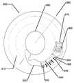
이제 도 1을 참조하면, 안과용 렌즈를 위한 예시적인 금형(100)의 도면이 에너지 공급원(109) 및 광원(109a)과 함께 예시되어 있다. 본 명세서에 사용되는 바와 같이, 금형이라는 용어는 렌즈 형성 혼합물의 반응 또는 경화 시에 원하는 형상의 안과용 렌즈가 생성되도록 렌즈 형성 혼합물이 내부에 분배될 수 있는 공동(105)을 갖는 단일 또는 다중-부분품 장치(100)를 포함한다. 본 발명의 금형 및 금형 조립체(100)는 하나 초과의 "금형 부분품" 또는 "금형 단편"(101, 102)으로 이루어진다. 금형 부분품(101, 102)은 공동(105)이 금형 부분품(101, 102) 사이에 형성되도록 함께 합쳐질 수 있으며, 렌즈가 공동 내부에서 형성될 수 있다. 금형 부분품(101, 102)의 이러한 조합은 바람직하게는 일시적이다. 렌즈의 형성 시에, 금형 부분품(101, 102)은 렌즈의 제거를 위해 다시 분리될 수 있다.Referring now to FIG. 1, an illustration of an
적어도 하나의 금형 부분품(101, 102)은 그 표면(103, 104)의 적어도 일부가 렌즈 형성 혼합물과 접촉하여, 렌즈 형성 혼합물의 반응 또는 경화 시에 상기 표면(103, 104)이 그가 접촉하는 렌즈의 부분에 원하는 형상 및 형태를 제공하게 한다. 적어도 하나의 다른 금형 부분품(101, 102)도 마찬가지이다.At least one mold part (101, 102) has at least a portion of its surface (103, 104) in contact with the lens forming mixture such that upon reaction or curing of the lens forming mixture, To provide the desired shape and shape to the portion of the surface. The same is true for at least one
따라서, 예를 들어, 바람직한 실시예에서, 금형 조립체(100)는 2개의 부분품(101, 102), 즉 그들 사이에 공동이 형성되는 암형 오목 단편(female concave piece)(전방 단편)(102) 및 수형 볼록 단편(male convex piece)(후방 단편)(101)으로부터 형성된다. 렌즈 형성 혼합물과 접촉하는 오목 표면(104)의 부분은 금형 조립체(100) 내에서 생성되는 안과용 렌즈의 전방 곡선의 곡률을 가지며, 오목 표면(104)과 접촉하는 렌즈 형성 혼합물의 중합에 의해 형성되는 안과용 렌즈의 표면이 광학적으로 허용가능하도록 형성되고 충분히 매끄럽다.Thus, for example, in a preferred embodiment, the
일부 실시예에서, 전방 금형 단편(102)은 또한 원형 원주방향 에지와 일체로 되어 이를 둘러싸는 환상 플랜지(annular flange)를 가질 수 있으며, 환상 플랜지는 축에 수직이고 플랜지로부터 연장하는 평면(도시 안됨) 내에서 원주방향 에지로부터 연장한다.In some embodiments, the
렌즈 형성 표면은 광학 품질의 표면 마무리를 가진 표면(103, 104)을 포함할 수 있는데, 이는 성형 표면과 접촉하는 렌즈 형성 재료의 중합에 의해 형성되는 렌즈 표면이 광학적으로 허용가능하도록 표면이 형성되고 충분히 매끄럽다는 것을 나타낸다. 또한, 일부 실시예에서, 렌즈 형성 표면(103, 104)은 구면, 비구면 및 원주 굴절력, 파면 수차 교정, 각막 토포그래피 교정 등 및 이들의 임의의 조합을 제한 없이 포함하는 원하는 광학적 특성을 렌즈 표면에 부여하기 위해 필요한 기하학적 형상을 가질 수 있다.The lens-forming surface may comprise
에너지 공급원(109) 및 광원(109a)이 그 상에 배치될 수 있는 매체가 도면 부호 111로 예시되어 있다. 매체(111)는 에너지 공급원(109) 및 광원(109a)이 그 상에 배치될 수 있는 임의의 수용 재료일 수 있으며, 일부 실시예에서는 또한 회로 경로, 구성요소(108) 및 에너지 공급원의 사용에 유용한 다른 양태를 포함할 수 있다. 일부 실시예에서, 매체(111)는 렌즈가 형성될 때 렌즈 내로 혼입될 수 있는 재료의 투명 코트(clear coat)일 수 있다. 투명 코트는 예를 들어 후술하는 바와 같은 안료, 단량체 또는 다른 생체적합성 재료를 포함할 수 있다. 추가 실시예는 강성이거나 성형성일 수 있는 삽입체를 포함하는 매체를 포함할 수 있다. 일부 실시예에서, 강성 삽입체는 광학적 특성을 제공하는 광학 구역(예컨대, 시력 교정을 위해 이용되는 것) 및 비-광학 구역 부분을 포함할 수 있다. 에너지 공급원(109)은 삽입체의 광학 구역과 비-광학 구역 중 하나 또는 둘 모두 상에 배치될 수 있다. 또 다른 실시예는 강성이거나 성형성인 환상 삽입체 또는 사용자가 이를 통해 보는 광학 구역을 에워싸는 소정의 형상부를 포함할 수 있다.A medium on which the
다양한 실시예는 또한 렌즈를 형성하기 위해 사용되는 금형 부분 내로 삽입체를 배치하기 전에 삽입체 상으로 에너지 공급원(109) 및 광원(109a)을 배치하는 것을 포함한다. 매체(111)는 또한 에너지 공급원(109)을 통해 전하를 수용할 하나 이상의 구성요소(108)를 가진 삽입체를 포함할 수 있다.Various embodiments also include disposing an
금형 부분품(101, 102) 재료는 예를 들어 폴리프로필렌, 폴리스티렌, 폴리에틸렌, 폴리메틸 메타크릴레이트, 및 개질 폴리올레핀 중 하나 이상의 폴리올레핀을 포함할 수 있다. 다른 금형은 세라믹 또는 금속 재료를 포함할 수 있다.The
바람직한 지환족 공중합체는 2가지의 상이한 지환족 중합체를 함유하며, 상표명 제오노르(ZEONOR)로 제온 케미칼스 엘.피.(Zeon Chemicals L.P.)에 의해 판매된다. 몇몇 상이한 등급의 제오노르가 있다. 다양한 등급이 105℃ 내지 160℃ 범위의 유리 전이 온도를 가질 수 있다. 특히 바람직한 재료는 제오노르 1060R이다.Preferred alicyclic copolymers contain two different alicyclic polymers and are sold by Zeon Chemicals L.P. under the trade designation ZEONOR. There are several different grades of Zeon Nor. Various grades may have glass transition temperatures in the range of < RTI ID = 0.0 > 105 C < / RTI > A particularly preferred material is Zeonor 1060R.
안과용 렌즈 금형을 형성하기 위해 하나 이상의 첨가제와 조합될 수 있는 다른 금형 재료는 예를 들어 지글러-나타(Zieglar-Natta) 폴리프로필렌 수지(때때로 znPP로 지칭됨)를 포함한다.Other mold materials that can be combined with one or more additives to form ophthalmic lens molds include, for example, Ziegler-Natta polypropylene resins (sometimes referred to as znPP).
또한 일부 실시예에서, 본 발명의 금형은 중합체, 예컨대 폴리프로필렌, 폴리에틸렌, 폴리스티렌, 폴리메틸 메타크릴레이트, 주 사슬 내에 지환족 부분(alicyclic moiety)을 함유한 개질 폴리올레핀, 및 환형 폴리올레핀을 함유할 수 있다. 이러한 블렌드는 금형 절반부들 중 어느 하나 또는 둘 모두에 사용될 수 있으며, 여기서 이러한 블렌드가 후방 곡선에 사용되고 전방 곡선이 지환족 공중합체로 이루어지는 것이 바람직하다.Also, in some embodiments, the mold of the present invention may contain a polymer such as polypropylene, polyethylene, polystyrene, polymethylmethacrylate, a modified polyolefin containing an alicyclic moiety in the main chain, and a cyclic polyolefin have. Such a blend may be used in either or both of the mold halves, wherein such blend is preferably used in the back curve and the forward curves in the alicyclic copolymer.
본 발명에 따라 금형(100)을 제조하는 일부 바람직한 방법에서, 사출 성형이 공지된 기술에 따라 이용되지만, 실시예는 또한 예를 들어 프리 폼 성형(free form molding), 선반 가공(lathing), 다이아몬드 선삭(diamond turning), 또는 레이저 커팅(laser cutting)을 비롯한 다른 기술에 의해 형성된 금형을 포함할 수 있다.In some preferred methods of making
전형적으로, 렌즈는 둘 모두의 금형 부분품(101, 102)의 적어도 하나의 표면 상에 형성된다. 그러나, 일부 실시예에서, 렌즈의 하나의 표면이 금형 부분품(101, 102)으로부터 형성될 수 있고, 렌즈의 다른 표면은 선반 가공 방법 또는 다른 방법을 사용하여 형성될 수 있다.Typically, a lens is formed on at least one surface of both
렌즈lens
이제 도 2를 참조하면, 안과용 렌즈(201)가 에너지 공급원(202), 광원(202a) 및 구성요소(203)와 함께 예시되어 있다.Referring now to FIG. 2, an
에너지 공급원(202)은 광원(202a) 및 구성요소(203)와 전기적 통신 상태에 있을 수 있다. 광원(202a)은 450 내지 500 나노미터, 가장 바람직하게는 470 내지 480 나노미터의 파장에서, 그리고 2,000 내지 3,000 룩스에서 청색 광을 방출하는 발광 다이오드(light-emitting diode, LED) 또는 다른 조명 장치를 포함할 수 있다. 대안적으로, LED 또는 다른 조명 장치는 475 내지 525 나노미터, 가장 바람직하게는 490 내지 510 나노미터의 파장에서, 그리고 300 내지 400 룩스에서 녹색 광을 방출할 수 있다. 다른 실시예에서, 단일 광원이 광 요법을 위해 요구되는 조명을 제공하기 위해 안과용 렌즈(201) 내의 하나 이상의 위치에 파이핑될(piped) 수 있다. 구성요소(203)는, 예를 들어 반도체 유형 칩(chip); 수동형 전기 장치; 수정 렌즈(crystal lens)와 같은 광학 장치; 프로세서, 마이크로-전기기계적 기계(MEMS) 또는 나노-전기기계적 기계(NEMS)와 같이, 상태의 변화에 의해 전하에 응답하는 임의의 장치를 포함할 수 있다.The
일부 특정 실시예에서, 구성요소(203)는, 예를 들어 커패시터; 울트라커패시터(ultracapacitor); 슈퍼커패시터(supercapacitor); 또는 다른 저장 구성요소와 같은 전기 저장 장치를 포함한다. 에너지 공급원(202)은, 예를 들어 광학 구역 외측의 안과용 렌즈의 주변부 내에 위치되고 무선 주파수, 광기전(photo voltaics) 및 자기 인덕턴스(magnetic inductance) 중 하나 이상을 통해 에너지 공급원(202) 내로 충전가능한 리튬 이온 배터리를 포함할 수 있다. 다른 에너지 공급원(202)이 아래에서 도 7을 참조하여 추가로 논의된다.In some particular embodiments,
예시된 바와 같이, 일부 실시예에서, 에너지 공급원 부분(202), 광원(202a) 및 구성요소(203)는 광학 구역(204) 외측에 위치되고, 여기서 광학 구역(204)은 렌즈(201)의 착용자를 위한 시선(line of sight)을 제공하는 렌즈(201)의 해당 부분을 포함한다. 다른 실시예는 안과용 렌즈의 광학 구역 부분 내에 에너지 공급원(202)을 포함할 수 있다. 예를 들어, 그러한 실시예는 너무 작아서 도움 없이는 사람 눈으로 볼 수 없는 전도성 입자들의 에너지 공급원(202)을 포함할 수 있다.As illustrated, in some embodiments, the
일부 실시예에서, 바람직한 렌즈 유형은 실리콘 함유 성분을 포함하는 렌즈(201)를 포함할 수 있다. "실리콘 함유 성분"은 단량체, 거대단량체(macromer) 또는 예비중합체 내에 적어도 하나의 [-Si-O-] 단위를 함유하는 것이다. 바람직하게는, 총 Si 및 부착된 O는 실리콘 함유 성분의 총 분자량의 약 20 중량% 초과, 더욱 바람직하게는 30 중량% 초과의 양으로 실리콘 함유 성분 내에 존재한다. 유용한 실리콘 함유 성분은 바람직하게는 중합성 작용기, 예컨대 아크릴레이트, 메타크릴레이트, 아크릴아미드, 메타크릴아미드, 비닐, N-비닐 락탐, N-비닐아미드, 및 스티릴 작용기를 포함한다.In some embodiments, the preferred lens type may include a
적합한 실리콘 함유 성분은 하기 화학식 I의 화합물을 포함한다:Suitable silicone-containing components include compounds of formula (I): < EMI ID =
[화학식 I](I)

여기서,here,
R1은 독립적으로 1가 반응성 기, 1가 알킬기, 또는 1가 아릴기 - 전술한 기 중 임의의 것은 하이드록시, 아미노 ,옥사, 카르복시, 알킬 카르복시, 알콕시, 아미도 ,카르바메이트, 카르보네이트, 할로겐 또는 이들의 조합으로부터 선택되는 작용기를 추가로 포함할 수 있음 - 와; 1개 내지 100개의 Si-O 반복 단위를 포함하는 1가 실록산 사슬 - 알킬, 하이드록시, 아미노, 옥사, 카르복시, 알킬 카르복시, 알콕시, 아미도, 카르바메이트, 할로겐 또는 이들의 조합으로부터 선택되는 작용기를 추가로 포함할 수 있음 - 로부터 선택되며;R1 is independently a monovalent reactive group, a monovalent alkyl group, or a monovalent aryl group-any of the foregoing groups may be optionally substituted with one or more substituents selected from the group consisting of hydroxy, amino, oxa, carboxy, alkylcarboxy, alkoxy, amido, carbamate, Which may further comprise a functional group selected from halogen, halogen, or combinations thereof; A functional group selected from monovalent siloxane chain-alkyl containing 1 to 100 Si-O repeating units, hydroxy, amino, oxa, carboxy, alkylcarboxy, alkoxy, amido, carbamate, halogen or combinations thereof - < / RTI >
여기서, b는 0 내지 500이고, b가 0 이외의 것일 때, b는 기술된 값과 동일한 모드를 가진 분포임이 이해되며;Where b is from 0 to 500 and b is other than 0, b is understood to be a distribution having the same mode as described;
여기서, 적어도 하나의 R1은 1가 반응성 기를 포함하고, 일부 실시예에서는 1개 내지 3개의 R1이 1가 반응성 기를 포함한다.Wherein at least one R <1 > comprises a monovalent reactive group, and in some embodiments from one to three R <1 > include a monovalent reactive group.
본 명세서에 사용되는 바와 같이, "1가 반응성 기"는 자유 라디칼 및/또는 양이온 중합을 겪을 수 있는 기이다. 자유 라디칼 반응성 기의 비제한적인 예는 (메트)아크릴레이트, 스티릴, 비닐, 비닐 에테르, C1-6알킬(메트)아크릴레이트, (메트)아크릴아미드, C1-6알킬(메트)아크릴아미드, N-비닐락탐, N-비닐아미드, C2-12알켄일, C2-12알켄일페닐, C2-12알켄일나프틸, C2-6알켄일페닐C1-6알킬, O-비닐카르바메이트 및 O-비닐카르보네이트를 포함한다. 양이온성 반응성 기의 비제한적인 예는 비닐 에테르 또는 에폭사이드기 및 이들의 혼합물을 포함한다. 일 실시예에서, 자유 라디칼 반응성 기는 (메트)아크릴레이트, 아크릴옥시, (메트)아크릴아미드, 및 이들의 혼합물을 포함한다.As used herein, " monovalent reactive group " is a group capable of undergoing free radical and / or cationic polymerization. Non-limiting examples of free radical reactive groups include (meth) acrylate, styryl, vinyl, vinyl ether, C1-6 alkyl (meth) acrylate, (meth) acrylamide, C1-6 alkyl amide, N- vinyl caprolactam, N- vinyl amide, C2-12 alkenyl, C2-12 alkenyl, phenyl, C2-12 alkenyl, naphthyl, C2-6 alkenyl, phenyl C1-6 alkyl, O -Vinyl carbamate and O-vinyl carbonate. Non-limiting examples of cationic reactive groups include vinyl ether or epoxide groups and mixtures thereof. In one embodiment, the free radical reactive groups include (meth) acrylate, acryloxy, (meth) acrylamide, and mixtures thereof.
적합한 1가 알킬 및 아릴기는 비치환된 1가 C1 내지 C16알킬기, C6-C14 아릴기, 예컨대 치환 및 비치환 메틸, 에틸, 프로필, 부틸, 2-하이드록시프로필, 프로폭시프로필, 폴리에틸렌옥시프로필, 이들의 조합 등을 포함한다.Suitable monovalent alkyl and aryl groups include unsubstituted monovalent C1 to C16 alkyl groups, C6 to C14 aryl groups such as substituted and unsubstituted methyl, ethyl, propyl, butyl, 2-hydroxypropyl, Polyethylene oxypropyl, combinations of these, and the like.
일 실시예에서, b는 0이며, 하나의 R1이 1가 반응성 기이고, 적어도 3개의 R1은 1개 내지 16개의 탄소 원자를 가진 1가 알킬기로부터 선택되며, 다른 실시예에서는 1개 내지 6개의 탄소 원자를 가진 1가 알킬기로부터 선택된다. 이러한 실시예의 실리콘 성분의 비제한적인 예는 2-메틸-,2-하이드록시-3-[3-[1,3,3,3-테트라메틸-1-[(트라이메틸실릴)옥시]다이실록사닐]프로폭시]프로필 에스테르("SiGMA"), 2-하이드록시-3-메타크릴옥시프로필옥시프로필-트리스(트라이메틸실록시)실란, 3-메타크릴옥시프로필트리스(트라이메틸실록시)실란("TRIS"), 3-메타크릴옥시프로필비스(트라이메틸실록시)메틸실란 및 3-메타크릴옥시프로필펜타메틸 다이실록산을 포함한다.In one embodiment, b is 0, one R1 is a monovalent reactive group, at least three R1 are selected from monovalent alkyl groups having 1 to 16 carbon atoms, and in another embodiment, Is selected from monovalent alkyl groups having 6 carbon atoms. Non-limiting examples of silicone components in this embodiment include 2-methyl-, 2-hydroxy-3- [3- [1,3,3,3-tetramethyl-1 - [(trimethylsilyl) oxy] 3-methacryloxypropyloxypropyl-tris (trimethylsiloxy) silane, 3-methacryloxypropyltris (trimethylsiloxy) silane ("TRIS"), 3-methacryloxypropylbis (trimethylsiloxy) methylsilane and 3-methacryloxypropylpentamethyldisiloxane.
다른 실시예에서, b는 2 내지 20, 3 내지 15 또는 일부 실시예에서 3 내지 10이며; 적어도 하나의 말단 R1은 1가 반응성 기를 포함하고, 나머지 R1은 1개 내지 16개의 탄소 원자를 가진 1가 알킬기로부터, 그리고 다른 실시예에서는 1개 내지 6개의 탄소 원자를 가진 1가 알킬기로부터 선택된다. 또 다른 실시예에서, b는 3 내지 15이며, 하나의 말단 R1은 1가 반응성 기를 포함하고, 다른 말단 R1은 1개 내지 6개의 탄소 원자를 가진 1가 알킬기를 포함하며, 나머지 R1은 1개 내지 3개의 탄소 원자를 가진 1가 알킬기를 포함한다. 이러한 실시예의 실리콘 성분의 비제한적인 예는 (모노-(2-하이드록시-3-메타크릴옥시프로필)-프로필 에테르 종결된 폴리다이메틸실록산 (400 내지 1000 MW)) ("OH-mPDMS"), 모노메타크릴옥시프로필 종결된 모노-n-부틸 종결된 폴리다이메틸실록산 (800 내지 1000 MW), ("mPDMS")을 포함한다.In another embodiment, b is 2 to 20, 3 to 15, or in some embodiments 3 to 10; At least one terminal R < 1 > comprises a monovalent reactive group and the remaining R < 1 > is selected from monovalent alkyl groups having from 1 to 16 carbon atoms, and in another embodiment from monovalent alkyl groups having from 1 to 6 carbon atoms Is selected. In another embodiment, b is from 3 to 15, one terminal R1 comprises a monovalent reactive group and the other terminal R1 comprises a monovalent alkyl group having from 1 to 6 carbon atoms and the remaining R1 Quot; includes monovalent alkyl groups having 1 to 3 carbon atoms. A non-limiting example of a silicone component in this embodiment is a polydimethylsiloxane (400-1000 MW) (" OH-mPDMS ") terminated with mono - (2 - hydroxy - 3 - methacryloxypropyl) , Monomethacryloxypropyl terminated mono-n-butyl terminated polydimethylsiloxane (800 to 1000 MW), (" mPDMS ").
다른 실시예에서, b는 5 내지 400 또는 10 내지 300이며, 두 말단 R1은 1가 반응성 기를 포함하고, 나머지 R1은 독립적으로 1개 내지 18개의 탄소 원자를 가진 1가 알킬기 - 이들은 탄소 원자들 사이에 에테르 결합을 가질 수 있으며 추가로 할로겐을 포함할 수 있음 - 로부터 선택된다.In another embodiment, b is from 5 to 400 or from 10 to 300, the two terminals R1 comprise a monovalent reactive group and the remaining R1 independently are monovalent alkyl groups having from 1 to 18 carbon atoms, Lt; / RTI > may have an ether linkage between them and may further contain a halogen.
일 실시예에서, 실리콘 하이드로겔 렌즈가 요구되는 경우, 본 발명의 렌즈는 중합체가 제조되는 반응성 단량체 성분의 총 중량을 기준으로 약 20 중량% 이상, 바람직하게는 약 20 내지 70 중량%의 실리콘 함유 성분을 포함하는 반응 혼합물로부터 제조될 것이다.In one embodiment, when a silicone hydrogel lens is desired, the lens of the present invention may comprise at least about 20 weight percent, preferably about 20 to about 70 weight percent silicon based on the total weight of reactive monomer components from which the polymer is made. ≪ / RTI > component.
다른 실시예에서, 1개 내지 4개의 R1은 하기 화학식 II의 비닐 카르보네이트 또는 카르바메이트를 포함한다:In another embodiment, one to four R1 comprises a vinyl carbonate or carbamate of the formula II:
[화학식 II]≪ RTI ID = 0.0 &

여기서, Y는 O-, S- 또는 NH-를 나타내며;Wherein Y represents O-, S- or NH-;
R은 수소 또는 메틸을 나타내고; d는 1, 2, 3 또는 4이며; q는 0 또는 1이다.R represents hydrogen or methyl; d is 1, 2, 3 or 4; q is 0 or 1;
실리콘 함유 비닐 카르보네이트 또는 비닐 카르바메이트 단량체는 구체적으로 하기를 포함한다: 1,3-비스[4-(비닐옥시카르보닐옥시)부트-1-일]테트라메틸-다이실록산; 3-(비닐옥시카르보닐티오) 프로필-[트리스(트라이메틸실록시)실란]; 3-[트리스(트라이메틸실록시)실릴] 프로필 알릴 카르바메이트; 3-[트리스(트라이메틸실록시)실릴] 프로필 비닐 카르바메이트; 트라이메틸실릴에틸 비닐 카르보네이트; 트라이메틸실릴메틸 비닐 카르보네이트, 및Silicon-containing vinylcarbonate or vinylcarbamate monomers specifically include: 1,3-bis [4- (vinyloxycarbonyloxy) but-1-yl] tetramethyl-disiloxane; 3- (vinyloxycarbonylthio) propyl- [tris (trimethylsiloxy) silane]; 3- [tris (trimethylsiloxy) silyl] propylallylcarbamate; 3- [tris (trimethylsiloxy) silyl] propyl vinylcarbamate; Trimethylsilylethyl vinyl carbonate; Trimethylsilylmethyl vinyl carbonate, and

약 200 미만의 모듈러스를 가진 생의학 장치가 요구될 경우, 단지 하나의 R1이 1가 반응성 기를 포함해야 하며, 나머지 R1기 중 둘 이하가 1가 실록산기를 포함할 것이다.When a biopsy device having a modulus of less than about 200 is desired, only one R1 must contain a monovalent reactive group, and two or less of the remaining R1 groups will comprise a monovalent siloxane group.
다른 부류의 실리콘 함유 성분은 하기 화학식들의 폴리우레탄 거대단량체를 포함한다:Another class of silicon containing components includes polyurethane macromonomers of the following formulas:
[화학식 IV](IV)
(*D*A*D*G)a*D*D*E1;(* D * A * D * G)a * D * D * E1 ;
[화학식 V](V)
E(*D*G*D*A)a *D*G*D*E1 또는;E (* D * G * D * A)a * D * G * D * E1 or;
[화학식 VI](VI)
E(*D*A*D*G)a *D*A*D*E1E (* D * A * D * G)a * D * A * D * E1
여기서,here,
D는 6개 내지 30개의 탄소 원자를 가진 알킬 다이라디칼(diradical), 알킬 사이클로알킬 다이라디칼, 사이클로알킬 다이라디칼, 아릴 다이라디칼 또는 알킬아릴 다이라디칼을 나타내고;D represents an alkyl diaradical having from 6 to 30 carbon atoms, an alkylcycloalkyl di radical, a cycloalkyl di radical, an aryl di radical or an alkyl aryl di radical;
G는 1개 내지 40개의 탄소 원자를 가지며, 에테르, 티오 또는 아민 결합을 주 사슬 내에 함유할 수 있는 알킬 다이라디칼, 사이클로알킬 다이라디칼, 알킬 사이클로알킬 다이라디칼, 아릴 다이라디칼 또는 알킬아릴 다이라디칼을 나타내고;G is an alkyl di radical having from 1 to 40 carbon atoms and containing an ether, thio or amine linkage in the main chain, a cycloalkyl di radical, an alkyl cycloalkyl di radical, an aryl di radical or an alkyl aryl di radical, ;
*는 우레탄 또는 우레이도 결합을 나타내며;* Represents a urethane or ureido bond;
a는 적어도 1이고;a is at least 1;
A는 하기 화학식:A is a group of the formula:
[화학식 VII](VII)

(R11은 독립적으로 탄소 원자들 사이에 에테르 결합을 함유할 수 있는, 1개 내지 10개의 탄소 원자를 가진 알킬 또는 플루오로-치환된 알킬기를 나타내며; y는 적어도 1이고; p는 400 내지 10,000의 부분 중량(moiety weight)을 제공함)의 2가 중합체 라디칼을 나타내며; 각각의 E 및 E1은 독립적으로 하기 화학식:(R11 represents an alkyl or fluoro-substituted alkyl group having 1 to 10 carbon atoms, which may independently contain an ether bond between carbon atoms, y is at least 1, p is from 400 to 10,000 Lt; RTI ID = 0.0 > of: < / RTI > Each E and <RTI ID = 0.0 > E1 < /RTI >
[화학식 VIII](VIII)

[여기서, R12는 수소 또는 메틸이며; R13은 수소, 1개 내지 6개의 탄소 원자를 가진 알킬 라디칼, 또는 -CO-Y-R15 라디칼 (여기서, Y는 -O-, Y-S- 또는 -NH-임)이고; R14은 1개 내지 12개의 탄소 원자를 가진 2가 라디칼이며; X는 -CO- 또는 -OCO-를 나타내고; Z는 -O- 또는 -NH-를 나타내며; Ar은 6개 내지 30개의 탄소 원자를 가진 방향족 라디칼을 나타내고; w는 0 내지 6이며; x는 0 또는 1이고; y는 0 또는 1이며; z는 0 또는 1임]로 나타내어지는 중합성 불포화 유기 라디칼을 나타낸다.Wherein R <12 > is hydrogen or methyl; R13 is hydrogen, an alkyl radical having 1 to 6 carbon atoms, or a -CO-YR15 radical where Y is -O-, YS- or -NH-; R14 is a divalent radical having 1 to 12 carbon atoms; X represents -CO- or -OCO-; Z represents -O- or -NH-; Ar represents an aromatic radical having 6 to 30 carbon atoms; w is 0 to 6; x is 0 or 1; y is 0 or 1; and z is 0 or 1. The term " polymerizable unsaturated organic radical "
바람직한 실리콘 함유 성분은 하기 화학식:A preferred silicon containing component has the formula:
[화학식 IX](IX)

(여기서, R16은 아이소포론 다이아이소시아네이트의 다이라디칼과 같은, 아이소시아네이트기의 제거 후 다이아이소시아네이트의 다이라디칼임)에 의해 나타내어지는 폴리우레탄 거대단량체이다. 다른 적합한 실리콘 함유 거대단량체는 플루오로에테르, 하이드록시-종결된 폴리다이메틸실록산, 아이소포론 다이아이소시아네이트 및 아이소시아나토에틸메타크릴레이트의 반응에 의해 형성되는 하기 화학식 X의 화합물(여기서, x + y는 10 내지 30 범위의 수임)이다:(Wherein R <16 > is a di-radical of a diisocyanate after removal of an isocyanate group, such as a di-radical of an isophorone diisocyanate). Other suitable silicon-containing macromonomers include compounds of the formula X wherein x + y is selected from the group consisting of fluoroether, hydroxy-terminated polydimethylsiloxane, isophorone diisocyanate and isocyanatoethylmethacrylate Is a number ranging from 10 to 30):
[화학식 X](X)

본 발명에 사용하기에 적합한 다른 실리콘 함유 성분은 폴리실록산, 폴리알킬렌 에테르, 다이아이소시아네이트, 폴리플루오르화 탄화수소, 폴리플루오르화 에테르 및 다당류 기를 함유한 거대단량체; 말단 다이플루오로치환된 탄소 원자에 부착된 수소 원자를 가진 극성 플루오르화 그래프트 또는 측쇄기를 가진 폴리실록산; 에테르 및 실록사닐 결합을 함유한 친수성 실록사닐 메타크릴레이트 및 폴리에테르 및 폴리실록사닐 기를 함유한 가교결합성 단량체를 포함한다. 전술한 폴리실록산 중 임의의 것은 또한 실리콘 함유 성분으로서 본 발명에서 사용될 수 있다.Other silicon containing components suitable for use in the present invention include macromonomers containing polysiloxanes, polyalkylene ethers, diisocyanates, polyfluorinated hydrocarbons, polyfluorinated ethers and polysaccharide groups; A polysiloxane having a polar fluorinated graft or side chain group having a hydrogen atom attached to a carbon atom substituted by a terminal difluoro; Hydrophilic siloxane methacrylates containing ether and siloxanyl bonds, and cross-linkable monomers containing polyether and polysiloxanyl groups. Any of the foregoing polysiloxanes may also be used in the present invention as silicon containing components.
공정fair
하기 방법 단계들은 본 발명의 일부 태양에 따라 구현될 수 있는 공정들의 예로서 제공된다. 방법 단계들이 제시되는 순서는 제한하고자 하는 것이 아니며 본 발명을 구현하기 위해 다른 순서가 사용될 수 있음을 이해하여야 한다. 또한, 본 발명을 구현하기 위해 단계들 모두가 필요한 것은 아니며 본 발명의 다양한 실시예에서 추가 단계가 포함될 수 있다.The following method steps are provided as examples of processes that may be implemented in accordance with some aspects of the present invention. It should be understood that the order in which the method steps are presented is not intended to be limiting and that other orders may be used to implement the invention. Moreover, not all of the steps are required to implement the present invention, and further steps may be included in various embodiments of the present invention.
이제 도 4를 참조하면, 흐름도는 본 발명을 구현하기 위해 사용될 수 있는 예시적인 단계들을 예시하며, 단계(401)에서 에너지 공급원 및 광원이 매체 상으로 배치된다. 매체는 하나 이상의 구성요소를 또한 포함하거나 포함하지 않을 수 있다.Referring now to FIG. 4, a flow diagram illustrates exemplary steps that may be used to implement the present invention, wherein an energy source and a light source are disposed on a medium, The media may also or may not include one or more components.
단계(402)에서, 반응성 단량체 혼합물이 금형 부분품(101, 102) 내로 침착될 수 있다.In
단계(403)에서, 매체가 금형 부분품 내에 배치된다. 일부 바람직한 실시예에서, 매체는 기계적 배치를 통해 금형 부분품 내에 배치된다. 기계적 배치는, 예를 들어 표면 장착 구성요소를 배치하기 위해 산업계에 알려진 것들과 같은 로봇 또는 다른 자동화 장치를 포함할 수 있다. 매체를 사람이 배치하는 것이 또한 본 발명의 범주 내에 있다. 따라서, 금형 부분품에 의해 함유된 반응성 혼합물의 중합에 의해 에너지 공급원 및 광원이 생성된 안과용 렌즈 내에 포함되도록, 에너지 공급원 및 광원을 가진 매체를 캐스트 금형 부분품 내에 배치하는 데 효과적인 임의의 기계적 배치가 이용될 수 있다.In
일부 실시예에서, 금형 부분품 상에 에너지 공급원 및 광원을 배치하기 전에 결합제 층이 금형 부분품에 적용될 수 있다. 결합제 층은, 비제한적인 예로서, 안료 또는 단량체를 포함할 수 있다. 결합 층은, 예를 들어 잉크 제팅(ink jetting) 또는 패드 인쇄(pad printing) 공정을 통해 적용될 수 있다. 일부 실시예에서, 프로세서 소자, MEMS, NEMS 또는 다른 구성요소는 또한 에너지 공급원과 전기 접촉 상태로 결합제 내에 배치될 수 있다.In some embodiments, a binder layer may be applied to the mold part prior to placing the energy source and light source on the mold part. The binder layer can include, as a non-limiting example, a pigment or a monomer. The bonding layer can be applied, for example, through an ink jetting or pad printing process. In some embodiments, the processor element, MEMS, NEMS, or other component may also be disposed in the binder in electrical contact with the energy source.
단계(404)에서, 제1 금형 부분품은 제2 금형 부분품에 근접하게 배치되어 렌즈 형성 공동이 형성되어, 반응성 단량체 혼합물의 적어도 일부, 에너지 공급원 및 광원이 공동 내에 있게 될 수 있다. 단계(405)에서, 공동 내의 반응성 단량체 혼합물은 중합될 수 있다. 중합은 예를 들어 화학 방사선 및 열 중 하나 또는 둘 모두에 대한 노출을 통해 달성될 수 있다. 단계(406)에서, 렌즈는 금형 부분품으로부터 제거된다.In
일부 실시예에서, 결합 층은 렌즈 재료와 상호침투성 중합체 네트워크(interpenetrating polymer network)를 형성할 수 있는 결합 중합체를 포함할 수 있어서, 안정된 렌즈를 형성하기 위해 결합제와 렌즈 재료 사이에 공유 결합을 형성할 필요성이 제거된다. 에너지 공급원 및 광원이 결합제 내에 배치된 렌즈의 안정성은 결합 중합체와 렌즈 베이스 중합체 내에 에너지 공급원 및 광원을 포획시킴으로써 제공된다. 본 발명의 결합 중합체는, 예를 들어 서로 유사한 용해도 파라미터를 가진 단일중합체 또는 공중합체 또는 이들의 조합으로부터 제조된 것들을 포함할 수 있으며, 결합 중합체는 렌즈 재료에 대해 유사한 용해도 파라미터를 갖는다. 결합 중합체는 결합 중합체의 중합체 및 공중합체가 서로 상호작용할 수 있게 하는 작용기를 함유할 수 있다. 작용기는 안료 입자의 이동성을 억제하고/하거나 안료 입자를 포획하는 것을 돕는 상호작용의 밀도를 증가시키는 방식으로 서로 상호작용하는 중합체 또는 공중합체의 기들을 포함할 수 있다. 작용기들 사이의 상호작용은 극성이거나, 분산성이거나 전하 전달 착물 특성의 것일 수 있다. 작용기는 중합체 또는 공중합체 골격 상에 위치되거나 골격으로부터의 펜던트일 수 있다.In some embodiments, the bonding layer may comprise a bonding polymer capable of forming an interpenetrating polymer network with the lens material to form a covalent bond between the bonding agent and the lens material to form a stable lens The need is eliminated. The stability of the lens in which the energy source and light source are disposed in the binder is provided by capturing energy sources and light sources within the binding polymer and the lens base polymer. The binding polymers of the present invention may comprise, for example, those prepared from homopolymers or copolymers or combinations thereof having similar solubility parameters, and the binding polymers have similar solubility parameters for the lens material. Bonding polymers may contain functional groups that allow the polymers and copolymers of the binding polymer to interact with each other. The functional groups may include groups of polymers or copolymers that interact with each other in such a way as to increase the density of the interactions that help to control the migration of the pigment particles and / or to trap the pigment particles. The interaction between the functional groups may be polar, dispersive or of charge transfer complex nature. The functional group may be located on the polymer or copolymer backbone or may be a pendant from the backbone.
비제한적인 예로서, 양 전하를 가진 중합체를 형성하는 단량체 또는 단량체들의 혼합물이 음 전하를 가진 중합체를 형성하는 단량체 또는 단량체들과 함께 사용되어 결합 중합체를 형성할 수 있다. 더욱 구체적인 예로서, 메타크릴산("MAA") 및 2-하이드록시에틸메타크릴레이트("HEMA")는 MAA/HEMA 공중합체를 제공하기 위해 사용될 수 있으며, 이 공중합체는 이어서 HEMA/3-(N, N-다이메틸) 프로필 아크릴아미드 공중합체와 혼합되어 결합 중합체를 형성한다.As a non-limiting example, a monomer or a mixture of monomers that form a polymer with a positive charge can be used with monomers or monomers to form a polymer having a negative charge to form a binding polymer. As a more specific example, methacrylic acid ("MAA") and 2-hydroxyethyl methacrylate ("HEMA") can be used to provide MAA / HEMA copolymers, which are subsequently reacted with HEMA / 3- (N, N-dimethyl) propyl acrylamide copolymer to form a binding polymer.
다른 예로서, 결합 중합체는 하기 화학식의 아미드 및 에스테르를 제한 없이 포함하는 소수성-개질된 단량체로 구성될 수 있다:As another example, the binding polymer may be composed of hydrophobic-modified monomers, which include, without limitation, amides and esters of the formula:
CH3(CH2)x-L-COCHR=CH2CH3 (CH2 )X -L-COCHR = CH2
(여기서, L은 -NH 또는 산소일 수 있으며, x는 2 내지 24의 정수일 수 있고, R은 C1 내지 C6 알킬 또는 수소일 수 있으며 바람직하게는 메틸 또는 수소임). 그러한 아미드와 에스테르의 예는 라우릴 메타크릴아미드 및 헥실 메타크릴레이트를 제한 없이 포함한다. 또 다른 예로서, 지방족 사슬 연장된 카르바메이트 및 우레아의 중합체가 결합 중합체를 형성하기 위해 사용될 수 있다.Wherein L can be -NH or oxygen, x can be an integer from 2 to 24, and R can be C1 to C6 alkyl or hydrogen and is preferably methyl or hydrogen. Examples of such amides and esters include, but are not limited to, lauryl methacrylamide and hexyl methacrylate. As another example, polymers of aliphatic chain extended carbamates and urea may be used to form the binding polymer.
결합 층(111)에 적합한 결합 중합체는 또한 HEMA, MAA 및 라우릴 메타크릴레이트("LMA")의 랜덤 블록 공중합체, HEMA와 MAA 또는 HEMA와 LMA의 랜덤 블록 공중합체, 또는 HEMA의 단일중합체를 포함할 수 있다. 이들 실시예에서 각각의 성분의 중량 백분율은, 결합 중합체의 총 중량을 기준으로, 약 93 내지 약 100 중량% HEMA, 약 0 내지 약 2 중량% MAA, 및 약 0 내지 약 5 중량% LMA이다.Bonding polymers suitable for
결합 중합체의 분자량은 결합 중합체가 렌즈 재료에서 다소 가용성이고 그 내에서 팽윤하도록 하는 것일 수 있다. 렌즈 재료는 결합 중합체 내로 확산하며 중합되고/되거나 가교결합된다. 그러나, 동시에, 결합 중합체의 분자량은 인쇄된 이미지의 품질에 영향을 줄 정도로 그리 높지는 않을 수 있다. 바람직하게는, 결합 중합체의 분자량은 약 7,000 내지 약 100,000, 더 바람직하게는 약 7,000 내지 약 40,000, 가장 바람직하게는 약 17,000 내지 약 35,000 Mpeak이며, 이는 SEC 분석에서 최대 피크의 분자량에 해당한다( = (Mn x Mw)½).The molecular weight of the binding polymer may be such that the binding polymer is somewhat soluble in the lens material and swells within it. The lens material diffuses into the bonding polymer and is polymerized and / or crosslinked. However, at the same time, the molecular weight of the binding polymer may not be so high as to affect the quality of the printed image. Preferably, the molecular weight of the binding polymer is from about 7,000 to about 100,000, more preferably from about 7,000 to about 40,000, and most preferably from about 17,000 to about 35,000 Mpeaks , which corresponds to the molecular weight of the maximum peak in the SEC analysis ( = (Mn x Mw )½ ).
본 발명의 목적을 위해, 분자량은 90° 광 산란 및 굴절률 검출기를 가진 겔 투과 크로마토그래프를 사용하여 결정될 수 있다. PW4000과 PW2500의 두 컬럼, 50 mM 염화나트륨으로 조정된 75/25 wt/wt의 메탄올-물 용리액 및 325,000 내지 194 범위의 잘 한정된 분자량을 가진 폴리에틸렌 글리콜과 폴리에틸렌 옥사이드 분자의 혼합물이 사용된다.For purposes of the present invention, the molecular weight can be determined using a gel permeation chromatograph with a 90 ° light scattering and index of refraction detector. A mixture of two columns of PW4000 and PW2500, a 75/25 wt / wt methanol-water eluate adjusted to 50 mM sodium chloride and a polyethylene glycol and polyethylene oxide molecule with a well defined molecular weight ranging from 325,000 to 194 are used.
당업자는 결합 중합체의 생성에 사슬 전달제를 사용함으로써, 다량의 개시제를 사용함으로써, 리빙 중합(living polymerization)을 사용함으로써, 적절한 단량체 및 개시제 농도를 선택함으로써, 용매의 양 및 유형을 선택함으로써, 또는 이들의 조합에 의해, 원하는 결합 중합체 분자량을 얻을 수 있음을 인식할 것이다. 바람직하게는, 사슬 전달제는 개시제와 함께, 또는 더 바람직하게는 개시제 및 하나 이상의 용매와 함께 사용되어 원하는 분자량을 달성한다. 대안적으로, 소량의 매우 높은 분자량의 결합 중합체가 다량의 용매와 함께 사용되어 결합 중합체에 대해 원하는 점도를 유지할 수 있다. 바람직하게는, 결합 중합체의 점도는 23℃에서 약 4,000 내지 약 15,000 센티푸아즈(centipoise)일 것이다.Those skilled in the art will appreciate that by using a chain transfer agent to create a binding polymer, by using a large amount of initiator, by using living polymerization, by selecting the appropriate monomer and initiator concentration, by selecting the amount and type of solvent, or It will be appreciated that combinations of these can provide the desired binding polymer molecular weights. Preferably, the chain transfer agent is used with an initiator, or more preferably with an initiator and at least one solvent to achieve the desired molecular weight. Alternatively, a small amount of a very high molecular weight binding polymer can be used with a large amount of solvent to maintain the desired viscosity for the binding polymer. Preferably, the viscosity of the binding polymer will be from about 4,000 to about 15,000 centipoise at 23 占 폚.
본 발명에 사용되는 결합 중합체를 형성하는 데 유용한 사슬 전달제는 약 0.01 초과, 바람직하게는 약 7 초과, 더 바람직하게는 약 25,000 초과의 사슬 전달 상수 값을 갖는다.Chain transfer agents useful for forming the binding polymers used in the present invention have a chain transfer constant value of greater than about 0.01, preferably greater than about 7, and more preferably greater than about 25,000.
자외선, 가시광선, 열 개시제 등 및 이들의 조합을 제한 없이 포함하는 임의의 바람직한 개시제가 사용될 수 있다. 바람직하게는, 열 개시제, 더 바람직하게는 2,2-아조비스 아이소부티로니트릴 및 2,2-아조비스 2-메틸부티로니트릴이 사용된다. 사용되는 개시제의 양은 제형의 총 중량을 기준으로 약 0.1 내지 약 5 중량%일 것이다. 바람직하게는, 2,2-아조비스 2-메틸부티로니트릴이 도데칸티올과 함께 사용된다.Any desired initiator may be used including, without limitation, ultraviolet light, visible light, thermal initiators, and the like, and combinations thereof. Preferably, a thermal initiator, more preferably 2,2-azobisisobutyronitrile and 2,2-azobis 2-methylbutyronitrile are used. The amount of initiator used will be from about 0.1 to about 5 weight percent, based on the total weight of the formulation. Preferably, 2,2-azobis 2-methylbutyronitrile is used with dodecanethiol.
결합 중합체 층 또는 다른 매체(111)는 라디칼 사슬 중합, 단계 중합, 에멀젼 중합, 이온 사슬 중합, 개환, 기 전달 중합, 원자 전달 중합 등을 제한 없이 포함하는 임의의 편리한 중합 과정에 의해 제조될 수 있다. 바람직하게는, 열-개시된 자유-라디칼 중합이 사용된다. 중합을 수행하기 위한 조건은 당업자의 지식 범위 내이다.The bonding polymer layer or other medium 111 may be prepared by any convenient polymerization process involving, without limitation, radical chain polymerization, step polymerization, emulsion polymerization, ion chain polymerization, ring opening, gas transfer polymerization, . Preferably, a heat-initiated free-radical polymerization is used. The conditions for carrying out the polymerization are within the knowledge of those skilled in the art.
결합 중합체의 생성에 유용한 용매는 약 120 내지 230℃의 비점을 가진 중비점 용매이다. 사용될 용매의 선택은 생성될 결합 중합체의 유형 및 그 분자량에 기초할 것이다 적합한 용매는 다이아세톤 알코올, 사이클로헥사논, 아이소프로필 락테이트, 3-메톡시 1-부탄올, 1-에톡시-2-프로판올 등을 제한 없이 포함한다.Solvents useful for the formation of the binding polymer are medium boiling point solvents having a boiling point of about 120 to 230 < 0 > C. The choice of solvent to be used will be based on the type of binder polymer to be produced and on its molecular weight. Suitable solvents are diacetone alcohols, cyclohexanone, isopropyl lactate, 3-methoxy 1-butanol, 1-ethoxy- And the like.
일부 실시예에서, 본 발명의 결합 중합체 층은 물에서의 팽창 계수 측면에서 함께 사용될 렌즈 재료에 맞춰질 수 있다. 결합 중합체의 팽창 계수를 패킹 용액(packing solution) 내의 경화된 렌즈 재료의 팽창 계수와 일치시키거나 실질적으로 일치시키는 것은 렌즈 내의 응력의 형성 - 이는 열등한 광학계 및 렌즈 파라미터 변이(parameter shift)로 이어짐 - 을 용이하게 피하게 할 수 있다. 추가로, 결합 중합체는 렌즈 재료 내에서 팽윤가능하여, 본 발명의 착색제를 사용하여 인쇄된 이미지가 팽윤되게 한다. 이러한 팽윤으로 인해, 이미지는 렌즈의 편안함에 어떠한 영향도 없이 렌즈 재료 내에 포획되게 된다.In some embodiments, the binding polymer layers of the present invention can be tailored to the lens material to be used together in terms of the coefficient of expansion in water. Matching or substantially matching the expansion coefficient of the bonding polymer with the coefficient of expansion of the cured lens material in the packing solution leads to the formation of stresses in the lens which leads to inferior optics and lens parameter shifts It can be easily avoided. Additionally, the binding polymer is swellable in the lens material, which causes the printed image to swell using the colorant of the present invention. Because of this swelling, the image is captured in the lens material without any effect on the comfort of the lens.
일부 실시예에서, 착색제가 결합 층 내에 포함될 수 있다. 본 발명의 착색제 내의 결합 중합체에 유용한 안료는 콘택트 렌즈에 사용하기 적합한 유기 또는 무기 안료 또는 그러한 안료들의 조합이다. 불투명도는 사용되는 안료 및 불투명화제의 농도를 변동시킴으로써 제어될 수 있으며, 이때 양이 많아질수록 불투명도가 더 커지게 된다. 예시적인 유기 안료는 프탈로시아닌 블루(pthalocyanine blue), 프탈로시아닌 그린(pthalocyanine green), 카르바졸 바이올렛(carbazole violet), 배트 오렌지(vat orange) # 1 등 및 이들의 조합을 제한 없이 포함한다. 유용한 무기 안료의 예는 흑색 산화철, 갈색 산화철, 황색 산화철, 적색 산화철, 이산화티타늄 등 및 이들의 조합을 제한 없이 포함한다. 이들 안료에 더하여, 다이클로로트라이아진 및 비닐 설폰계 염료를 제한 없이 포함하는 가용성 및 불용성 염료가 사용될 수 있다. 유용한 염료 및 안료는 구매가능하다.In some embodiments, a colorant may be included in the binding layer. The pigments useful in the binding polymers in the colorants of the present invention are organic or inorganic pigments or combinations of such pigments suitable for use in contact lenses. Opacity can be controlled by varying the concentration of the pigment and opacifying agent used, with the greater the amount of opacity becoming larger. Exemplary organic pigments include, without limitation, pthalocyanine blue, pthalocyanine green, carbazole violet,
결합 중합체를 이용한 안료 입자의 코팅 또는 습윤은 벌크 결합 중합체에서의 안료 입자의 더 우수한 분산을 제공한다. 코팅은 정전기력, 분산력 또는 수소 결합력을 사용하여 안료의 표면을 덮음으로써 달성될 수 있다. 바람직하게는, 안료를 결합 중합체 내로 분산시키기 위해 고전단력이 사용된다. 안료는 중합체와 안료를 적합한 믹서, 예컨대 회전축 믹서(rotary shaft mixer) 내로 분배하고 균질한 혼합물이 생성될 때까지, 전형적으로 최대 약 30분의 기간 동안 혼합함으로써 결합 중합체에 첨가될 수 있다. 이어서, 혼합물은 안료를 결합 중합체 내로 분산시키기 위해 고전단 밀(mill), 예컨대 아이거 밀(Eiger mill) 내로 공급될 수 있다. 완전한 분산을 달성하기 위해 필요한 대로 반복되는 밀링(milling)이 수행된다. 일반적으로, 밀링은 안료의 크기가 약 0.2 내지 약 3 마이크로미터일 때까지 수행된다. 밀링은 고전단 또는 볼 밀링(ball milling) 장치를 제한 없이 포함하는 임의의 적합한 구매가능한 장치를 사용하여 수행될 수 있다.The coating or wetting of the pigment particles with the binding polymer provides a better dispersion of the pigment particles in the bulk binding polymer. The coating can be achieved by covering the surface of the pigment using electrostatic, dispersive or hydrogen bonding forces. Preferably, a high shear force is used to disperse the pigment into the binding polymer. The pigment may be added to the binding polymer by distributing the polymer and pigment into a suitable mixer, such as a rotary shaft mixer, and mixing until a homogeneous mixture is formed, typically for a period of up to about 30 minutes. The mixture may then be fed into a high shear mill, such as an Eiger mill, to disperse the pigment into the binding polymer. Repetitive milling is performed as necessary to achieve complete dispersion. Generally, the milling is carried out until the size of the pigment is about 0.2 to about 3 micrometers. Milling may be performed using any suitable commercially available apparatus, including, without limitation, high shear or ball milling apparatus.
안료 및 결합 중합체에 더하여, 일부 실시예에서, 결합 층은 금형 부분품 상으로 결합 층을 코팅하는 것을 돕는 하나 이상의 용매를 함유한다. 결합 층이 적용되는 금형 부분품 표면 상에서 흘러 나오거나 흐르지 않는 결합 층을 용이하게 하기 위해, 결합 층이 약 27 mN/m 미만의 표면 장력을 갖는 것이 바람직하며 그리고 요구된다는 것이 본 발명의 다른 발견이다. 이러한 표면 장력은 결합 층(111)이 적용될 표면, 예를 들어 금형 표면의 처리에 의해 달성될 수 있다. 표면 처리는 플라즈마 및 코로나 처리와 같은, 그러나 이에 제한되지 않는 당업계에 알려진 방법에 의해 달성될 수 있다. 대안적으로, 그리고 바람직하게는, 원하는 표면 장력은 착색제에 사용되는 용매의 선택에 의해 달성될 수 있다.In addition to pigments and binding polymers, in some embodiments, the bonding layer contains at least one solvent that aids in coating the bonding layer onto the mold parts. It is another discovery of the present invention that it is desirable and desirable for the bonding layer to have a surface tension of less than about 27 mN / m, in order to facilitate bonding layers that do not flow out or flow on the surface of the mold part to which the bonding layer is applied. This surface tension can be achieved by the treatment of the surface to which the
따라서, 결합 층에 유용한 예시적인 용매는 결합 층의 점도를 증가 또는 감소시킬 수 있으며 표면 장력을 제어하는 것을 돕는 용매를 포함한다. 적합한 용매는 사이클로펜타논, 4-메틸-2-펜타논, 1-메톡시-2-프로판올, 1-에톡시-2-프로판올, 아이소프로필 락테이트 등 및 이들의 조합을 제한 없이 포함한다. 바람직하게는, 1-에톡시-2-프로판올 및 아이소프로필 락테이트가 사용된다.Thus, exemplary solvents useful for the bonding layer include solvents that can increase or decrease the viscosity of the bonding layer and help control surface tension. Suitable solvents include, without limitation, cyclopentanone, 4-methyl-2-pentanone, 1-methoxy-2-propanol, 1-ethoxy-2-propanol, isopropyl lactate, and the like, and combinations thereof. Preferably, 1-ethoxy-2-propanol and isopropyl lactate are used.
일부 바람직한 실시예에서, 적어도 3가지 상이한 용매가 본 발명의 결합 층 재료에 사용된다. 이들 용매 중 처음의 둘 - 이들 둘 모두 중비점 용매임 - 은 결합 중합체의 생성에 사용된다. 이들 용매가 형성 후 결합 중합체로부터 제거될 수 있지만, 용매가 보유되는 것이 바람직하다. 바람직하게는, 이들 두 용매는 1-에톡시-2-프로판올 및 아이소프로필 락테이트이다. 비점이 약 75 내지 약 120℃인 용매를 의미하는 추가의 저비점 용매가 원하는 대로 착색제의 점도를 감소시키도록 사용될 수 있다. 적합한 저비점 용매는 2-프로판올, 1-메톡시-2-프로판올, 1-프로판올 등 및 이들의 조합을 제한 없이 포함한다. 바람직하게는, 1-프로판올이 사용된다.In some preferred embodiments, at least three different solvents are used in the bonding layer material of the present invention. The first two of these solvents, both of which are medium boiling point solvents, are used to form the binding polymer. Although these solvents can be removed from the binding polymer after formation, it is preferred that the solvent be retained. Preferably, the two solvents are 1-ethoxy-2-propanol and isopropyl lactate. An additional low boiling solvent, which means a solvent having a boiling point of from about 75 to about 120 DEG C, may be used to reduce the viscosity of the colorant as desired. Suitable low boiling solvents include, without limitation, 2-propanol, 1-methoxy-2-propanol, 1-propanol, and the like, and combinations thereof. Preferably, 1-propanol is used.
사용되는 용매의 구체적인 양은 많은 인자들에 좌우될 수 있다. 예를 들어, 결합 중합체를 형성하는 데 사용되는 용매의 양은 원하는 결합 중합체의 분자량 및 결합 중합체에 사용되는 구성성분, 예컨대 단량체 및 공중합체에 좌우될 것이다. 사용되는 저비점 용매의 양은 착색제에 대해 요구되는 점도 및 표면 장력에 좌우될 것이다. 또한, 착색제가 금형에 적용되어 렌즈 재료와 함께 경화되는 경우, 사용되는 용매의 양은 사용되는 렌즈 및 금형 재료와, 이 금형 재료가 그의 습윤성을 증가시키기 위해 임의의 표면 처리를 거쳤는지 여부에 좌우될 것이다. 사용될 용매의 정확한 양을 결정하는 것은 당업자의 범위 내이다. 일반적으로, 사용되는 용매의 총 중량은 약 40 내지 약 75 중량%일 것이다.The specific amount of solvent used may depend on many factors. For example, the amount of solvent used to form the binding polymer will depend upon the molecular weight of the desired binding polymer and the components used for the binding polymer, such as monomers and copolymers. The amount of low boiling solvent used will depend on the viscosity and surface tension required for the colorant. In addition, when the colorant is applied to the mold and cured together with the lens material, the amount of solvent used depends on the lens and mold material used and whether the mold material has undergone any surface treatment to increase its wettability will be. It is within the skill of the art to determine the exact amount of solvent to be used. Generally, the total weight of the solvent used will be from about 40 to about 75 weight percent.
용매에 더하여, 가소제가 결합 층에 첨가될 수 있으며 바람직하게는 첨가되어, 결합 층의 건조 동안 균열을 감소시키고 렌즈 재료에 의한 결합 층의 확산 및 팽윤을 향상시킨다. 사용되는 가소제의 유형 및 양은 사용되는 결합 중합체의 분자량에 좌우될 것이며, 사용 전에 저장되는 금형 상에 배치되는 착색제의 경우 저장-수명(shelf-life) 안정성이 요구된다. 유용한 가소제는 글리세롤, 프로필렌 글리콜, 다이프로필렌 글리콜, 트라이프로필렌 글리콜, 폴리에틸렌 글리콜 200, 400 또는 600 등 및 이들의 조합을 제한 없이 포함한다. 바람직하게는, 글리세롤이 사용된다. 사용되는 가소제의 양은 일반적으로 착색제의 중량을 기준으로 0 내지 약 10 중량%일 것이다.In addition to the solvent, a plasticizer can be added to the bonding layer and is preferably added to reduce cracking during drying of the bonding layer and improve diffusion and swelling of the bonding layer by the lens material. The type and amount of plasticizer used will depend on the molecular weight of the bonding polymer used and the shelf-life stability of colorants placed on the mold prior to use is required. Useful plasticizers include, without limitation, glycerol, propylene glycol, dipropylene glycol, tripropylene glycol,
당업자는 논의된 것 이외의 첨가제가 또한 본 발명의 결합 층 조성물에 포함될 수 있음을 인식할 것이다. 적합한 첨가제는 유동 및 레벨링(leveling)을 돕는 첨가제, 발포 방지를 위한 첨가제, 리올로지(rheology) 변경을 위한 첨가제 등 및 이들의 조합을 제한 없이 포함한다.Those skilled in the art will recognize that additives other than those discussed can also be included in the binder layer compositions of the present invention. Suitable additives include, but are not limited to, additives that aid flow and leveling, additives to prevent foaming, additives for rheology modification, and the like, and combinations thereof.
본 발명의 일부 실시예에서, 결합 층은 렌즈 재료의 경화 시에 렌즈 재료 내에 매립되게 된다. 따라서, 결합 층은 렌즈 결합 층이 적용되는 금형의 표면에 따라 형성되는 렌즈의 전방 또는 후방 표면에 더 가깝게 매립될 수 있다. 추가로, 결합 층의 하나 이상의 층이 임의의 순서로 적용될 수 있다.In some embodiments of the present invention, the bonding layer is embedded in the lens material upon curing of the lens material. Thus, the bonding layer can be embedded closer to the front or rear surface of the lens formed along the surface of the mold to which the lens bonding layer is applied. In addition, one or more layers of the bonding layer may be applied in any order.
임의의 공지된 렌즈 재료 또는 그러한 렌즈의 제조에 적합한 재료로 제조된 하드 또는 소프트 콘택트 렌즈를 제공하기 위해 본 발명이 사용될 수 있지만, 바람직하게는 본 발명의 렌즈는 약 0 내지 약 90%의 수분 함량을 가진 소프트 콘택트 렌즈이다. 더욱 바람직하게는, 렌즈는 하이드록시기, 카르복실기 또는 둘 모두를 함유한 단량체로 제조되거나, 실리콘 함유 중합체, 예컨대 실록산, 하이드로겔, 실리콘 하이드로겔, 및 이들의 조합으로부터 제조된다. 본 발명의 렌즈를 형성하는 데 유용한 재료는 거대단량체, 단량체 및 이들의 조합의 블렌드를 중합 개시제와 같은 첨가제와 함께 반응시킴으로써 제조될 수 있다. 적합한 재료는 실리콘 거대단량체 및 친수성 단량체로부터 제조된 실리콘 하이드로겔을 제한 없이 포함한다.Although the present invention can be used to provide a hard or soft contact lens made of any known lens material or material suitable for the manufacture of such a lens, preferably the lens of the present invention has a moisture content of from about 0% to about 90% Lt; / RTI > More preferably, the lens is made of a monomer containing a hydroxyl group, a carboxyl group, or both, or is prepared from a silicone-containing polymer such as a siloxane, a hydrogel, a silicone hydrogel, and combinations thereof. Materials useful for forming the lenses of the present invention may be prepared by reacting blends of macromonomers, monomers, and combinations thereof with additives such as polymerization initiators. Suitable materials include, but are not limited to, silicone macromonomers and silicone hydrogels made from hydrophilic monomers.
이제 도 5를 참조하면, 본 발명의 다른 태양에서, 매체 상에 장착된 에너지 공급원 및 광원이 안과용 렌즈를 형성하기 위한 금형 공동 내에 배치된다. 단계(501)에서, 에너지 공급원 및 광원이 상기 논의된 바와 같이 안과용 렌즈 금형 부분품 내에 배치된다.Referring now to FIG. 5, in another aspect of the present invention, an energy source and a light source mounted on a medium are disposed in a mold cavity for forming an ophthalmic lens. In
단계(502)에서, 에너지 공급원이, 광원 또는 매체 상에 추가로 장착되어 금형 부분품 내에 배치된 다른 구성요소와 전기적 통신 상태로 배치된다. 전기적 통신은, 예를 들어 삽입체 내에 통합된 회로를 통해, 또는 잉크 제팅되거나 달리 렌즈 재료 상에 직접 형성된 경로를 통해 달성될 수 있다.In
단계(503)에서, 공동 내에 배치된 반응성 혼합물이 중합되어 렌즈를 형성한다. 중합은 예를 들어 화학 방사선에 대한 반응성 혼합물의 노출에 의해 달성될 수 있다.In
장치Device
이제 도 3을 참조하면, 자동화된 장치(310)가 하나 이상의 매체 전달 인터페이스(media transfer interface)(311)와 함께 예시되어 있다. 예시된 바와 같이, 관련 매체(314)를 각각 갖는 다수의 금형 부분품이 팔레트(pallet)(313) 상에 보유되고 매체 전달 인터페이스(311)에 제공된다. 실시예는 에너지 공급원 및 광원을 다수의 매체(314) 내에 개별적으로 배치하는 단일 인터페이스(311), 또는 에너지 공급원들 및 광원들을 다수의 매체, 예컨대 금형 부분품들(314) 내에 그리고 일부 실시예에서는 각각의 금형 내에 동시에 배치하는 다수의 인터페이스(도시 안됨)를 포함할 수 있다.Referring now to FIG. 3, an
일부 실시예의 다른 태양은 안과용 렌즈 에너지 공급원 및 광원을 포함하는 다양한 구성요소 주위에 안과용 렌즈의 본체가 성형되는 동안 이들 구성요소를 지지하기 위한 장치를 포함한다. 일부 실시예에서, 에너지 공급원 및 광원은 렌즈 금형(예시 안됨) 내의 홀딩 포인트(holding point)에 부착될 수 있다. 홀딩 포인트에는 렌즈 본체 내에 형성될 동일한 유형의 중합된 재료가 부착될 수 있다.Other aspects of some embodiments include an apparatus for supporting these components while the body of the ophthalmic lens is being molded around various components including an ophthalmic lens energy source and a light source. In some embodiments, the energy source and the light source may be attached to a holding point in a lens mold (not shown). The holding point may be attached with the same type of polymerized material to be formed in the lens body.
이제 도 6을 참조하면, 본 발명의 일부 실시예에 사용될 수 있는 컨트롤러(600)가 예시되어 있다. 컨트롤러(600)는 프로세서(610)를 포함하며, 이는 통신 장치(620)에 결합된 하나 이상의 프로세서 구성요소를 포함할 수 있다. 일부 실시예에서, 컨트롤러(600)는 안과용 렌즈 내에 배치된 에너지 공급원 및 광원에 에너지를 전송하기 위해 사용될 수 있다.Referring now to FIG. 6, a
컨트롤러는 통신 채널을 통해 에너지를 전달하도록 구성된 통신 장치에 결합된 하나 이상의 프로세서를 포함할 수 있다. 통신 장치는 안과용 렌즈 내로의 에너지 공급원의 배치 및 안과용 렌즈로의 그리고 안과용 렌즈로부터의 디지털 데이터의 전송 또는 안과용 렌즈 내로 통합된 광원 또는 다른 구성요소의 제어 중 하나 이상을 전자적으로 제어하기 위해 사용될 수 있다.The controller may include one or more processors coupled to a communication device configured to transmit energy over a communication channel. The communication device may be configured to electronically control one or more of the arrangement of the energy source into the ophthalmic lens and the transmission of digital data to and from the ophthalmic lens or the light source or other components incorporated into the ophthalmic lens Lt; / RTI >
통신 장치(620)는 또한, 예를 들어 하나 이상의 컨트롤러 장치 또는 제조 장비 구성요소와 통신하기 위해 사용될 수 있다.The
프로세서(610)는 또한 저장 장치(630)와 통신한다. 저장 장치(630)는 자기 저장 장치(예컨대, 자기 테이프 및 하드 디스크 드라이브), 광학 저장 장치, 및/또는 반도체 메모리 장치, 예컨대 랜덤 액세스 메모리(RAM) 장치 및 판독 전용 메모리(ROM) 장치의 조합을 비롯한 임의의 적절한 정보 저장 장치를 포함할 수 있다.The
저장 장치(630)는 프로세서(610)를 제어하기 위한 프로그램(640)을 저장할 수 있다. 프로세서(610)는 프로그램(640)의 명령어를 수행하며, 이로써 본 발명에 따라 작동한다. 저장 장치(630)는 또한 하나 이상의 데이터베이스에 눈 관련 데이터를 저장할 수 있다. 데이터베이스는 맞춤형 에너지 공급원 및 광원 설계, 도량형 데이터, 및 에너지 공급원 및 광원으로의 그리고 그로부터의 에너지를 제어하기 위한 특정 제어 시퀀스(control sequence)를 포함할 수 있다.The
일부 실시예에서, 안과용 렌즈는 안과용 장치 내에 통합된 에너지 공급원으로부터 에너지를 제공하도록 작동하는 활성화 구성요소를 구비한다.In some embodiments, the ophthalmic lens includes an activation component that is operative to provide energy from an energy source integrated within the ophthalmic device.
이제 도 7을 참조하면, 동력공급형 안과용 렌즈(100) 내에 매립될 수 있는 상이한 유형의 에너지 공급원에 포함될 수 있는 선택사양들 중 일부의 도면이 도 7에 항목(700)으로서 설명되어 있다. 앞서 언급된 바와 같이, 에너지 공급원의 일 세트의 실시예는 배터리를 포함할 수 있다. 배터리는 도 7에서 항목(720)으로 설명되어 있다. 도 7은 또한 다양한 선택사양들이 저장할 수 있는 에너지의 밀도의 순서로 다양한 선택사양들의 그래프를 설명한다. 배터리는 예를 들어 약 50 내지 약 800 Whr/L의 에너지 밀도의 영역을 포함한다. 일반적으로, 특정 에너지 공급원의 다른 양태를 고려하지 않고서, 에너지 저장의 밀도가 높을수록 더 바람직한 공급원이 될 것이다.Referring now to FIG. 7, a diagram of some of the options that may be included in different types of energy sources that may be embedded in power-powered
이러한 그래프(700)를 참조하면, 항목(740)인 에너지 하베스터는 에너지 밀도의 관점에서 가장 덜 바람직할 것임을 알 수 있다. 그러나, 당업자에게는, 에너지 하베스터가 이점을 가질 다른 방식이 존재하는 것이 명백할 수 있다.Referring to this
예를 들어, 에너지 하베스터는 광기전 에너지 전지(photovoltaic energy cell), 열전 전지(thermoelectric cell) 또는 압전 전지(piezoelectric cell)를 포함할 수 있다. 이러한 하베스터는 이들이 환경으로부터 에너지를 흡수할 수 있고 이어서 유선 연결 없이 전기 에너지를 제공할 수 있다는 점에서 긍정적인 양태를 갖는다. 일부 실시예에서, 하베스터는 동력공급형 안과용 렌즈 내의 공급원을 구성할 수 있다. 그러나, 다른 실시예에서, 에너지 하베스터는 에너지를 전기 형태로 저장할 수 있는 다른 공급원과 조합될 수 있다.For example, the energy harvester may include a photovoltaic energy cell, a thermoelectric cell, or a piezoelectric cell. These harvesters have a positive aspect in that they can absorb energy from the environment and then provide electrical energy without a wired connection. In some embodiments, the harvester may constitute a source in a powered ophthalmic lens. However, in other embodiments, the energy harvester may be combined with other sources capable of storing energy in an electrical form.
다른 유형의 에너지 공급원은 커패시터 유형 장치(730)를 포함한다. 커패시터가 에너지 하베스터보다는 높지만 배터리(720)의 그것보다는 낮은 에너지 밀도 솔루션을 포함한다는 것이 명백할 수 있다. 그럼에도 불구하고, 커패시터는 일부 고유의 이점을 갖는다.Another type of energy source includes a
커패시터는 에너지를 전기 형태로 저장하는 에너지 공급원의 유형이며; 따라서 에너지를 저장할 수 있는 무선 에너지 공급원을 생성하도록 에너지 하베스터와 조합될 수 있는 에너지 공급원들 중 하나일 수 있다. 일반적으로, 커패시터는 이들이 일반적으로 배터리보다 높은 전력 밀도를 갖는다는 점에서 배터리에 비해 이점을 갖는다. 표준 전기 박막 커패시터로부터, 마일라 커패시터(Mylar capacitor), 전해 커패시터(electrolytic capacitor) 및 비교적 더 새롭고 더 진보된 기술의 고밀도 나노스케일 커패시터(nanoscale capacitor) 또는 슈퍼커패시터에 이르는 많은 상이한 유형의 커패시터가 있다.A capacitor is a type of energy source that stores energy in an electrical form; And thus can be one of the energy sources that can be combined with an energy harvester to produce a wireless energy source capable of storing energy. In general, capacitors have advantages over batteries in that they generally have a higher power density than a battery. There are many different types of capacitors, ranging from standard electrical thin film capacitors, to Mylar capacitors, electrolytic capacitors, and to relatively high-density nanoscale or supercapacitors of newer and more advanced technology.
일부 추가의 실시예에서, 전기화학 전지 또는 배터리(720)를 포함하는 에너지 공급원은 비교적으로 바람직한 작동 포인트(operational point)를 한정할 수 있다. 배터리는 다수의 유리한 특징을 갖는다. 예를 들어, 배터리는 전기 에너지로 직접 변환되는 형태로 에너지를 저장한다. 일부 배터리는 재충전가능하거나 재동력공급가능할 수 있어서, 에너지 하베스터에 결합될 수 있는 다른 범주의 에너지 공급원을 나타낸다. 비교적 높은 에너지 밀도의 배터리에 의해, 배터리가 저장하는 에너지는 알맞은 에너지 요건을 갖는 기능을 수행할 수 있다. 또한, 배터리는 가요성인 형태로 조립될 수 있다. 높은 전력 용량을 필요로 하는 응용의 경우, 당업자에게는 배터리가 또한 커패시터에 결합될 수 있다는 것이 명백할 수 있다. 동력공급형 안과용 렌즈 내에 적어도 에너지 공급원의 일부로서 배터리를 포함하는 다수의 실시예가 있을 수 있다.In some additional embodiments, the energy source comprising the electrochemical cell or
다른 유형의 실시예는 에너지 공급원으로서 연료 전지(710)를 포함할 수 있다. 연료 전지는, 이어서 열 에너지를 포함한 부산물 및 전기를 발생시키는 화학 연료 공급원을 소비함으로써 전기를 발생시킨다. 연료 전지 실시예는 생물학적으로 이용가능한 재료를 연료 공급원으로서 사용하는 것이 가능할 수 있다. 그러나, 일반적으로, 이러한 에너지 공급원에 의해 제공되는 바람직한 에너지 밀도를 제외하고는, 이는 기술적으로 복잡하고 전형적으로 눈 응용에 요구되는 필수적인 소형 스케일의 것이 아닐 수 있다는 단점을 가질 수 있다. 또한, 연료 공급원이 눈 환경으로부터 소정의 방식으로 추출될 수 없는 경우, 이는 재동력공급될 수 있는 에너지 공급원과 비교할 때 실제 에너지 밀도에서 단점을 가질 수 있다.Other types of embodiments may include a
본 발명의 실시예에 대한 하기의 논의는 대체로 동력공급형 안과용 렌즈의 주 에너지 공급원으로서 배터리를 사용하는 데 중점을 둘 수 있다. 이러한 중점적인 논의는, 이상 논의된 것을 포함한 다수의 에너지 공급원이 동력공급형 안과용 렌즈의 실시예를 구성할 수 있기 때문에, 본 발명의 기술의 범주를 제한하지는 않을 것이다.The following discussion of embodiments of the present invention can generally focus on using batteries as the primary energy source for power-powered ophthalmic lenses. This focused discussion will not limit the scope of the technology of the present invention, as multiple energy sources, including those discussed above, can constitute embodiments of power-powered ophthalmic lenses.
본 발명의 일부 실시예에서 언급된 바와 같이, 에너지 공급원은 전기화학 전지 또는 배터리를 포함한다. 동력공급형 안과용 렌즈의 실시예에 포함될 수 있는 많은 상이한 유형의 배터리가 있다. 예를 들어, 일회용 배터리가 다양한 캐소드(cathode) 및 애노드(anode) 재료로부터 형성될 수 있다. 비제한적인 예로서, 이들 재료는 아연, 탄소, 은, 망간, 코발트, 리튬, 규소를 포함할 수 있다. 또 다른 실시예가 재충전가능한 배터리의 사용으로부터 유래될 수 있다. 그러한 배터리는 이어서, 리튬 이온 기술; 은 기술; 마그네슘 기술; 니오븀 기술 또는 다른 전류 제공 재료 중 하나 이상으로 제조될 수 있다. 당업자에게는, 일회용 또는 재충전가능 배터리 시스템을 위한 다양한 현재의 배터리 기술이 동력공급형 안과용 렌즈의 다양한 실시예에서 에너지 공급원을 구성할 수 있다는 것이 명백할 수 있다.As mentioned in some embodiments of the present invention, the energy source includes an electrochemical cell or a battery. There are many different types of batteries that may be included in embodiments of power-powered ophthalmic lenses. For example, disposable batteries can be formed from a variety of cathode and anode materials. As a non-limiting example, these materials may include zinc, carbon, silver, manganese, cobalt, lithium, silicon. Yet another embodiment may result from the use of a rechargeable battery. Such a battery can then be fabricated using lithium ion technology; Technology; Magnesium technology; Niobium technology or other current providing materials. It will be apparent to those skilled in the art that a variety of current battery technologies for disposable or rechargeable battery systems can constitute an energy source in various embodiments of power-powered ophthalmic lenses.
콘택트 렌즈 환경의 물리적 및 치수적 제약으로 인해 다른 것에 비해 소정의 배터리 유형이 유리할 수 있다. 이러한 유리함의 예는 박막 배터리의 경우에 이루어질 수 있다. 박막 배터리는 사람 눈에서의 실시와 양립하는 작은 체적의 공간을 점유할 수 있다. 또한, 이들은 가요성인 기판 상에 형성될 수 있어서, 안과용 렌즈 및 포함된 배터리 둘 모두의 본체가 기판과 함께 자유롭게 휘어지도록 한다.Certain battery types may be advantageous over others due to physical and dimensional constraints of the contact lens environment. An example of this advantage can be achieved in the case of a thin film battery. Thin film batteries can occupy a small volume of space compatible with the implementation in the human eye. They can also be formed on a flexible substrate such that the body of both the ophthalmic lens and the contained battery is free to flex with the substrate.
박막 배터리의 경우에, 예는 일회 충전 및 재충전가능한 형태를 포함할 수 있다. 재충전가능 배터리는 연장된 가용 제품 수명 및 이에 따른 보다 높은 에너지 소비율의 능력을 제공한다. 많은 개발 활동이 재충전가능 박막 배터리를 구비한 전기적으로 동력공급되는 안과용 렌즈를 제조하기 위한 기술에 중점을 두었지만; 본 발명의 기술은 이러한 하위부류에 제한되지 않는다.In the case of a thin film battery, examples may include a one time charge and rechargeable form. Rechargeable batteries provide extended battery life and thus higher energy consumption. Although many development activities have focused on techniques for manufacturing electrically powered ophthalmic lenses with rechargeable thin film batteries, The techniques of the present invention are not limited to these subclasses.
재충전가능 박막 배터리는 구매가능하며, 예를 들어 오크 리지 내셔널 레브러터리(Oak Ridge National Laboratory)는 1990년대 초부터 다양한 형태를 제조하였다. 그러한 배터리의 현재 상용 제조업체는 엑셀라트론 솔리드 스테이트, 엘엘씨(Excellatron Solid State, LLC)(미국 조지아주 애틀랜타), 인피니트 파워 솔루션즈(Infinite Power Solutions)(미국 콜로라도주 리틀턴), 및 심벳 코포레이션(Cymbet Corporation)(미국 미네소타주 엘크 리버)을 포함한다. 이 기술은 현재 평평한 박막 배터리를 포함하는 사용에 의해 주도된다. 그러한 배터리의 사용은 본 발명의 기술의 일부 실시예를 구성할 수 있지만; 박막 배터리를 예를 들어 구면 곡률 반경을 갖는 3차원 형상으로 형성하는 것이 본 발명의 기술의 바람직한 실시예를 구성한다. 당업자에게는 그러한 3차원 배터리 실시예의 다수의 형상 및 형태가 본 발명의 범주 내에 있다는 것이 명확할 수 있다.Rechargeable thin-film batteries are available, for example, Oak Ridge National Laboratory has produced various forms since the early 1990s. Current commercial manufacturers of such batteries include Excellatron Solid State, LLC (Atlanta, Ga.), Infinite Power Solutions (Littleton, Colo.), And Cymbet Corporation Corporation (Elk River, Minnesota, USA). This technology is currently dominated by the use of flat thin-film batteries. The use of such a battery may constitute some embodiments of the technology of the present invention; It is a preferred embodiment of the technique of the present invention to form the thin film battery in, for example, a three-dimensional shape having a spherical radius of curvature. It will be clear to those skilled in the art that many of the shapes and forms of such three-dimensional battery embodiments are within the scope of the present invention.
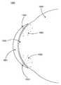
도 8a, 도 8b, 도 8c 및 도 8d에, 안과용 렌즈 내의 에너지 공급원이 취할 수 있는 상이한 형상의 다수의 예가 있다. 항목(800)은 참조를 위해 평평한 형상으로서 형성되는, 박막 재료로 제조된 기준 에너지 공급원을 도시한다. 그러한 형상(800)의 치수가 대략 1 밀리미터 정도일 때, 그것은 동력공급형 안과용 렌즈를 위한 에너지 공급원을 구성할 수 있다. 항목(810)은, 가요성 있게 뒤틀리지 않은 때 뒤틀리지 않은 안과용 렌즈가 취할 수 있는 형상과 대략 동일한 형상인, 가요성 기판 및 봉지된 배터리가 완전한 환상 형상을 취하는 예시적인 3차원 형태를 도시한다. 일부 실시예에서, 환상 형상의 반경은 동력공급형 안과용 렌즈 실시예의 경우 대략 8 밀리미터일 수 있다. 동일한 3차원 양태가 1/4 환체(830) 또는 1/2 환체(820)인 실시예에 의해 공유될 수 있다. 당업자에게는 다른 부분 환상 형상을 포함한 많은 상이한 형상이 본 발명의 범주 내에서 대안적인 실시예를 구성할 수 있다는 것이 명백할 수 있다.8A, 8B, 8C and 8D, there are a number of examples of different shapes that an energy source in an ophthalmic lens can take.
본 발명의 다른 세트의 실시예는 유리하게는 동력공급형 안과용 렌즈에 이용될 수 있는 특정 배터리 화학작용에 관한 것이다. 오크 리지 레브러터리에 의해 개발된 예시적인 실시예는 리튬 또는 리튬-이온 전지의 구성성분을 포함한다. 그러한 전지의 애노드를 위한 통상의 재료는 리튬 금속을 포함할 수 있거나, 대안적으로 리튬 이온 전지의 경우 흑연을 포함할 수 있다. 이들 전지의 예시적인 대안적 실시예는 콘택트 렌즈 내에 통합된 그러한 박막 배터리의 애노드로서 작용하기 위한 마이크로-스케일의 규소 특징부의 통합일 것이다.Another set of embodiments of the present invention is directed to certain battery chemistries that may advantageously be used in powered power ophthalmic lenses. Exemplary embodiments developed by Oak Ridge Laboratories include components of lithium or lithium-ion batteries. Typical materials for the anode of such a cell may comprise lithium metal or alternatively may comprise graphite in the case of a lithium ion cell. An exemplary alternative embodiment of these cells would be the integration of micro-scale silicon features to serve as the anode of such a thin film battery integrated into the contact lens.
이러한 신규한 기술에 사용되는 배터리의 캐소드를 위해 사용되는 재료는 또한 다수의 재료 선택사양을 포함할 수 있다. 통상의 캐소드 재료는 그에 따라 형성된 배터리에 대한 우수한 성능 지표(performance metric)를 갖는 리튬 망간 산화물 및 리튬 코발트 산화물을 포함할 것이다. 대안적으로, 리튬 철 인화물 캐소드가 유사한 성능을 가질 수 있지만, 일부 응용에서 충전에 관한 개선된 양태를 가질 수 있다. 또한, 이들 및 다른 캐소드 재료의 치수는 충전 성능을 개선시킬 수 있으며; 예를 들어 다양한 재료의 나노-스케일 결정체(nano-scaled crystal)로부터 캐소드를 형성하는 것은 배터리가 재충전될 수 있는 비율을 현저히 개선시킬 수 있다.The material used for the cathode of the battery used in this novel technique may also include a number of material options. Conventional cathode materials will include lithium manganese oxide and lithium cobalt oxide with good performance metrics for the battery thus formed. Alternatively, lithium iron phosphide cathodes may have similar performance, but may have improved aspects of charging in some applications. Also, the dimensions of these and other cathode materials can improve charging performance; For example, forming a cathode from a nano-scaled crystal of various materials can significantly improve the rate at which the battery can be recharged.
일부 실시예는 에너지 공급원 및 광원을 이들이 배치되는 환경으로부터 에너지 공급원 및 광원을 격리시키는 재료로 봉지하는 것을 포함할 수 있다. 일반적으로 그 구성성분을 눈 환경으로 진입하지 못하게 격리시키기 위해 에너지 공급원 및 광원을 봉지시키는 것이 바람직할 수 있다. 대안적으로, 눈 환경의 양태들은 이들이 봉지 실시에 의해 적절하게 격리되지 않을 경우 에너지 공급원 및 광원의 성능에 부정적인 영향을 미칠 수 있다. 본 발명의 기술의 다양한 실시예가 재료의 선택으로부터 유래될 수 있다.Some embodiments may include encapsulating the energy source and the light source with a material that isolates the energy source and the light source from the environment in which they are disposed. In general, it may be desirable to encapsulate the energy source and the light source to isolate the components from entering the eye environment. Alternatively, aspects of the eye environment may have a negative impact on the performance of the energy source and light source if they are not adequately isolated by the bag implementation. Various embodiments of the techniques of the present invention can be derived from the selection of materials.
도 9를 참조하면, 동력공급형 안과용 렌즈의 예시적인 실시예의 도면인 항목(900)이 도시되어 있다. 이러한 도면에서, 에너지 공급원(910)은 박막의 재충전가능 리튬 이온 배터리를 포함할 수 있다. 배터리는 상호접속을 가능하게 하기 위해 접점(970)을 구비할 수 있다. 와이어는 접점(970)으로의 와이어 접합 와이어일 수 있으며, 배터리 에너지 공급원(910)에 재동력공급하도록 사용될 수 있는 광전지(960)에 배터리를 연결시킬 수 있다. 부가적인 와이어가 에너지 공급원을 제2 세트의 접점(950) 상의 와이어 접합된 접촉부를 통해 가요성 회로 상호접속부에 연결시킬 수 있다. 이들 접점(950)은 광원(930)을 또한 포함할 수 있는 가요성 상호접속 기판(955)의 일부분일 수 있다. 이러한 상호접속 기판은 앞서 논의된 에너지 공급원과 유사한 방식으로 전형적인 렌즈 형태와 유사한 형상으로 형성될 수 있다. 그러나, 추가의 가요성을 부가하기 위해, 상호접속 기판(955)은 그 길이를 따라 반경방향 절결부(945)와 같은 부가적인 형상 특징부를 포함할 수 있다. 상호접속 기판(955)의 개별 플랩(flap) 상에, IC, 별개의 구성요소, 수동형 구성요소 및 항목(990)으로서 도시된 그러한 장치와 같은 다양한 전자 구성요소가 연결될 수 있다. 이들 구성요소는 와이어 또는 다른 연결 수단(940)에 의해 상호접속 기판(955) 내의 전도 경로에 상호접속된다. 비제한적인 예로서, 다양한 구성요소는 이미 논의된 배터리로의 상호접속이 이루어질 수 있게 하는 다양한 수단에 의해 가요성 상호접속 기판(955)에 연결될 수 있다. 다양한 전기 구성요소들의 조합은 항목(990)으로서 도시된 전기-광학 장치를 위한 제어 신호를 한정할 수 있다. 이러한 제어 신호는 상호접속부(920)를 따라 전도될 수 있다. 동력공급식 기능을 갖는 이러한 유형의 예시적인 동력공급형 안과용 렌즈는 단지 예의 목적으로 제공된다. 기능, 설계, 상호접속 계획, 동력공급 계획 및 본 발명의 개념의 전체적인 이용에 대한 많은 상이한 실시예가 존재할 수 있다는 것이 당업자에게 명백할 수 있기 때문에, 결코 이러한 설명을 본 발명의 기술의 범주를 제한하는 것으로 해석하여서는 안 된다.Referring to Fig. 9, there is shown an
일부 실시예에서, 안과용 렌즈의 외양에 영향을 주는 방식들이 존재할 수 있다. 박막 마이크로배터리 표면의 미적 특성은 전기활성 접촉 렌즈 또는 형상화된 하이드로겔 물품 내에 매립된 때 특정 외양을 나타내는 다양한 방식으로 변경될 수 있다. 일부 실시예에서, 박막 마이크로배터리는, 박막 마이크로배터리의 무채색(muted) 외양을 제공하거나 대안적으로 홍채와 유사한 유색 패턴, 단색(solid color) 및/또는 혼색(mixed color) 패턴, 반사성 설계, 무지갯빛 설계, 금속성 설계, 또는 잠재적으로 임의의 다른 예술적 설계 또는 패턴을 제공하는 역할을 할 수 있는 미적으로 만족스러운 패턴화된 및/또는 유색 패키징 재료로 생성될 수 있다. 다른 실시예에서, 박막 배터리는 렌즈 내의 다른 구성요소, 예를 들어 배터리 전방 표면에 장착된 광기전 칩에 의해, 또는 대안적으로 가요성 회로의 전부 또는 일부 후방에 배터리를 배치함으로써 부분적으로 가려질 수 있다. 추가의 실시예에서, 박막 배터리는 상안검 또는 하안검이 배터리의 가시성을 부분적으로 또는 전체적으로 차단하도록 전략적으로 위치될 수 있다. 당업자에게는 동력공급형 안과용 장치의 외양에 관한 다수의 실시예 및 이들을 한정하는 방법이 존재한다는 것이 명백할 수 있다.In some embodiments, there may be ways that affect the appearance of the ophthalmic lens. The aesthetic properties of the thin film microbicide surface can be varied in a variety of ways that exhibit a particular appearance when embedded in an electroactive contact lens or shaped hydrogel article. In some embodiments, the thin film micro-battery may provide a muted appearance of a thin film micro-battery, or alternatively may provide an iris-like colored pattern, a solid color and / or a mixed color pattern, a reflective design, Or colored packaging material that can serve to provide light design, metallic design, or potentially any other artistic design or pattern. In another embodiment, the thin film battery is partially obscured by placing the battery in another element in the lens, for example, by a photovoltaic chip mounted on the battery front surface, or alternatively by all or some of the back of the flexible circuit . In a further embodiment, the thin film battery may be strategically positioned such that the upper eyelid or lower eyepiece blocks the visibility of the battery partially or wholly. It will be apparent to those skilled in the art that there are numerous embodiments and ways of defining them with respect to the appearance of power-powered ophthalmic devices.
기술된 다양한 유형의 동력공급형 안과용 장치를 형성하는 방법에 관한 다수의 실시예가 있을 수 있다. 일 세트의 실시예에서, 본 명세서의 발명의 기술은 특정 동력공급형 안과용 렌즈 실시예의 하위구성요소들을 별도의 단계로 조립하는 것을 포함할 수 있다. 생체적합성의, 불활성 컨포멀 코팅(conformal coating)과 함께 유리하게 형상화된 박막 마이크로배터리, 가요성 회로, 상호접속부, 마이크로전자 구성요소, 및/또는 다른 전기활성 구성요소의 "오프-라인(off-line)" 조립은 표준 콘택트 렌즈 제조 공정으로 간단하게 통합될 수 있는 포괄적인(all-inclusive), 매립가능한 단일 패키지(singular package)를 제공한다. 가요성 회로는 동박(copper clad) 폴리이미드 필름 또는 다른 유사한 기판으로부터 제조된 것을 포함할 수 있다. 컨포멀 코팅은 파릴렌(등급 N, C, D, HT, 및 이들의 임의의 조합), 폴리(p-크실렌), 유전체 코팅, 실리콘 컨포멀 코팅, 또는 임의의 다른 유리한 생체적합성 코팅을 포함할 수 있지만, 이에 제한되지 않는다.There may be a number of embodiments relating to methods of forming the various types of power-supply ophthalmic devices described. In one set of embodiments, the inventive teachings herein may comprise assembling the sub-components of a particular powered, ophthalmic lens embodiment in separate steps. Off-line "of thin film micro batteries, flexible circuits, interconnects, microelectronic components, and / or other electro-active components that are advantageously shaped with a biocompatible, inactive conformal coating. line "assembly provides a singular package that is all-inclusive and can be easily integrated into standard contact lens manufacturing processes. The flexible circuit may include those made from a copper clad polyimide film or other similar substrate. The conformal coating may comprise parylene (grades N, C, D, HT, and any combination thereof), poly (p-xylene), dielectric coating, silicone conformal coating, or any other advantageous biocompatible coating But are not limited thereto.
본 발명의 일부 실시예는 안과용 렌즈 재료 내에 매립되고/되거나 그에 의해 봉지될 수 있는 기하학적 형상에 있어서 박막 마이크로배터리의 기하학적 형상 설계에 관한 방법일 수 있다. 다른 실시예는 박막 마이크로배터리를, 하이드로겔, 실리콘 하이드로겔, 강성 기체-투과성 "RGP" 콘택트 렌즈 재료, 실리콘, 열가소성 중합체, 열가소성 탄성중합체, 열경화성 중합체, 컨포멀 유전체/절연 코팅, 및 기밀 장벽 코팅(hermetic barrier coating)과 같은, 하지만 이에 제한되지 않는 다양한 재료 내에 통합시키는 방법을 포함할 수 있다.Some embodiments of the present invention may be directed to the geometric shape design of a thin film micro-battery in a geometric shape that may be embedded and / or encapsulated in an ophthalmic lens material. Other embodiments include coating a thin film microbattery on a substrate such as a hydrogel, a silicone hydrogel, a rigid gas-permeable " RGP " contact lens material, a silicone, a thermoplastic polymer, a thermoplastic elastomer, a thermoset polymer, a conformal dielectric / such as but not limited to a hermetic barrier coating.
다른 실시예는 안과용 렌즈 기하학적 형상 내에 에너지 공급원 및 광원을 전략적으로 배치하기 위한 방법을 포함할 수 있다. 구체적으로, 일부 실시예에서 에너지 공급원 및 광원은 불투명한 물품일 수 있다. 에너지 공급원 및 광원이 안과용 렌즈를 통한 광의 투과를 차단하지 않을 수 있기 때문에, 설계 방법은 일부 실시예에서 콘택트 렌즈의 중앙의 5 내지 8 ㎜가 에너지 공급원 및 광원의 임의의 불투명한 부분에 의해 차단되지 않을 수 있는 것을 보장할 수 있다. 당업자에게는 안과용 렌즈의 광학적으로 관련된 부분과 유리하게 상호작용하도록 다양한 에너지 공급원 및 광원을 설계하는 것에 관한 많은 상이한 실시예가 있을 수 있다는 것이 명백할 수 있다.Other embodiments may include a method for strategically placing an energy source and a light source within an ophthalmic lens geometry. Specifically, in some embodiments, the energy source and the light source may be opaque articles. Because the energy source and the light source may not block the transmission of light through the ophthalmic lens, the design methodology may, in some embodiments, be such that 5-8 mm of the center of the contact lens is blocked by the energy source and any opaque portion of the light source It can guarantee that It will be apparent to those skilled in the art that there may be many different embodiments with respect to designing the various energy sources and light sources to advantageously interact with the optically relevant portions of the ophthalmic lens.
일부 실시예에서, 에너지 공급원의 질량 및 밀도는 상기 에너지 공급원이 또한 단독으로 또는 렌즈를 눈 상에 있는 동안 회전적으로 안정시키기 위해 안과용 렌즈의 본체 내에 설계된 다른 렌즈 안정화 구역과 함께 기능할 수 있도록 설계를 용이하게 할 수 있다. 그러한 실시예는 난시의 교정, 개선된 눈 상에서의 편안함, 또는 동력공급형 안과용 렌즈 내에서의 다른 구성요소의 일관된/제어된 위치를 포함하지만 이에 제한되지 않는 다수의 응용에 유리할 수 있다.In some embodiments, the mass and density of the energy source are designed to function together with other lens stabilization zones designed within the body of the ophthalmic lens to stabilize the energy source either alone or while the lens is in the eye . Such an embodiment may be advantageous for a number of applications including, but not limited to, correction of astigmatism, improved eye comfort, or a consistent / controlled position of other components within a powered eye lens.
추가의 실시예에서, 에너지 공급원 및 광원은 우수한 편안함을 제공하는 동시에 불리한 상황의 발생을 최소화하도록 콘택트 렌즈 에지 프로파일의 유리한 설계를 가능하게 하기 위해 콘택트 렌즈의 외부 에지로부터 소정 거리에 배치될 수 있다. 회피되어야 할 그러한 불리한 상황의 예는 상부 상피 아치형 손상(superior epithelial arcuate lesions) 또는 거대 유두 결막염(giant papillary conjunctivitis)을 포함할 수 있다.In a further embodiment, the energy source and the light source may be positioned a predetermined distance from the outer edge of the contact lens to provide favorable comfort while allowing favorable design of the contact lens edge profile to minimize the occurrence of adverse situations. Examples of such adverse conditions to be avoided may include superior epithelial arcuate lesions or giant papillary conjunctivitis.
일부 실시예에서 비-제한적인 예로서, 매립된 전기화학 전지의 캐소드, 전해질 및 애노드 특징부는 그러한 캐소드, 전해질 및 애노드 영역을 한정하는 형상으로 적절한 잉크를 인쇄함으로써 형성될 수 있다. 이와 같이 형성된 배터리가 예를 들어 산화망간 및 아연의 화학작용에 기초한 일회용 전지 및 상기 언급된 박막 배터리의 화학작용과 유사한 리튬의 화학작용에 기초한 재충전가능한 얇은 배터리 둘 모두를 포함할 수 있다는 것이 명백할 수 있다. 당업자에게는 동력공급형 안과용 렌즈를 형성하는 다양한 특징 및 방법의 다양한 상이한 실시예가 인쇄 기술의 사용을 수반할 수 있다는 것이 명백할 수 있다.In some embodiments, as a non-limiting example, the cathode, electrolyte, and anode features of the buried electrochemical cell may be formed by printing appropriate ink in a shape defining such cathode, electrolyte, and anode regions. It is evident that the battery thus formed may comprise both a disposable battery based on the chemical action of, for example, manganese oxide and zinc and a rechargeable thin battery based on the chemistry of lithium similar to the chemistry of the aforementioned thin film battery . It will be apparent to those skilled in the art that a wide variety of different embodiments of various features and methods of forming power-powered ophthalmic lenses may involve the use of printing techniques.
이제 도 10을 참조하면, 단면도(1000)는 광(1003)을 눈(1005)의 각막(1004) 상으로 지향시키는 매립된 광원(1002)을 구비한, 콘택트 렌즈(1001)로도 지칭되는, 동력공급형 안과용 렌즈(1001)를 포함한다. 일부 실시예에서, 단면도(1000)는 평면도일 수 있으며, 이 경우 하나 이상의 매립된 광원(1002)은 콘택트 렌즈(1001)의 측면 부근에 배치된다. 다른 실시예에서, 단면도(1000)는 측면도일 수 있어서, 하나 이상의 매립된 광원(1002)은 콘택트 렌즈(1001)의 상부 및 저부 부근에 배치된다. 콘택트 렌즈(1001)의 주연부 둘레의 광원(1002)의 수 및 광원(1002)의 배열은 달라질 수 있다. 광원(1002)은 착용자의 눈을 향해 조명을 지향시켜서, 조명은 관찰자에게는 분명하게 보이지 않는다. 콘택트 렌즈(1001)는 또한 사용자의 광 요법 또는 시력을 약화시키지 않으면서, 광 요법 발광을 관찰자에 의해 용이하게 인지되지 않도록 차폐하는 코팅을 포함할 수 있다.Referring now to Figure 10, a
매립된 광원(1002)은 발광 다이오드(LED) 또는 광 요법을 위한 광(1003)을 방출하는 다른 광원(1002)을 포함한다. 광원(1002)은 450 내지 500 나노미터, 가장 바람직하게는 470 내지 480 나노미터의 파장에서, 그리고 2,000 내지 3,000 룩스에서 청색 광을 방출하는 발광 다이오드(LED) 또는 다른 조명 장치를 포함할 수 있다. 대안적으로, LED 또는 다른 조명 장치는 475 내지 525 나노미터, 가장 바람직하게는 490 내지 510 나노미터의 파장에서, 그리고 300 내지 400 룩스에서 녹색 광을 방출할 수 있다. 다른 실시예는 단일 광원을 포함하며, 이로부터의 광이 조명을 제공하기 위해 콘택트 렌즈(1001) 내의 하나 이상의 위치에 파이핑된다.The embedded
콘택트 렌즈(1001)는 예를 들어 광 센서, 에너지 공급원, 커패시터, 메모리, 프로세서 및 통신 장치와 같은 구성요소를 갖는 예시되지 않은 지원 전자장치를 포함한다. 광 센서는 주변 백색 광, 청색 광 또는 녹색 광을 검출하기 위해 사용된다. 에너지 공급원 및 커패시터는 동력공급형 안과용 렌즈의 다른 구성요소에 에너지를 공급한다. 메모리는, 비제한적인 예로서, 사전-프로그램된 광 요법 스케줄을 저장하기 위해, 광 센서에 의해 캡처된 데이터를 저장하기 위해, 실제 광 요법 날짜, 시간, 지속기간 및 강도를 저장하기 위해, 그리고 장치 고장을 검출하도록 광원 및 광 센서 작동과 관련된 데이터를 저장하기 위해 사용될 수 있다. 프로세서는, 예를 들어 메모리 내에 저장된 프로그램된 광 요법 스케줄을 실행시키기 위해, 광 센서 데이터를 분석하고 착용자의 주변 광에 대한 노출에 기초하여 고유의 광 요법 스케줄을 결정하기 위해, 프로그램된 광 요법 스케줄에 대한 수동 변경을 평가하고 보상 조정을 제공하기 위해, 그리고 장치 고장을 검출하도록 광원 및 광 센서 데이터를 분석하기 위해 사용될 수 있다.The
통신 장치는 동력공급형 안과용 렌즈 및 외부 장치로의 그리고 그로부터의 디지털 데이터의 전송, 및 동력공급형 안과용 렌즈 내의 구성요소들 사이의 디지털 테이터의 전송 중 하나 이상을 전자적으로 제어하기 위해 사용될 수 있다. 통신 장치는 비제한적인 예로서 동력공급형 안과용 렌즈를 제어하기 위해 사용되는 포브(fob), 휴대 정보 단말기(PDA) 또는 스마트폰 어플리케이션과 같은 하나 이상의 외부 장치와 무선 통신하는 데 사용될 수 있다. 동력공급형 안과용 렌즈 내에서, 구성요소들 사이의 통신은 직접적인 전도성 경로를 통해서와 같은 물리적 연결을 통해 이루어질 수 있거나, 무선일 수 있다. 내부 구성요소들 사이의 통신은, 예를 들어 프로세서로부터의 광원의 제어 및 광 센서와 메모리 사이의 데이터 전송을 포함할 수 있다.The communication device may be used to electronically control at least one of a powered ophthalmic lens and a transmission of digital data to and from an external device and transmission of the digital data between components within the powered ophthalmic lens have. The communication device may be used to wirelessly communicate with one or more external devices, such as a fob, a personal digital assistant (PDA) or a smartphone application, used to control a powered eye lens as a non-limiting example. Within a powered ophthalmic lens, communication between components can be via a physical connection, such as through a direct conductive path, or wireless. Communication among the internal components may include, for example, control of the light source from the processor and data transfer between the optical sensor and the memory.
지원 전자장치는 콘택트 렌즈(1001) 내에 포함된 광원(1002)과 논리적 및 전기적 통신 상태에 있다. 통신은 지원 전자장치와 광원(1002) 사이의 직접적인 전도성 경로를 통해 또는 무선 통신을 통해 이루어질 수 있다. 통신의 무선 모드는, 예를 들어 콘택트 렌즈(1001) 내의 광원(1002)에 근접하게 위치된 안테나 및 콘택트 렌즈(1001) 내의 다른 영역으로부터 안테나로 전력을 전송하는 전원을 통해 달성되는 인덕턴스를 포함할 수 있다.The supporting electronic device is in logical and electrical communication with the
일부 실시예에서, 지원 전자장치는 광 센서가 사용자가 경험하는 주변 광을 검출하고 지원 전자장치가 무선 통신의 목적을 위해 콘택트 렌즈 부근에 있도록, 사용자에 의해 착용되는 포브, 장신구, 모자, 의류, 또는 다른 물품 내에 포함될 수 있다. 통신의 무선 모드는 예를 들어 인덕턴스를 포함할 수 있다. 인덕턴스는 콘택트 렌즈 내에 위치된 안테나 및 장신구, 의류 또는 다른 근접한 물품 내의 지원 전자장치로부터 안테나로 전력을 전송하는 전원을 통해 달성될 수 있다.In some embodiments, the supporting electronic device is configured to detect the ambient light experienced by the user, and the supporting electronic device may be in the vicinity of the contact lens for the purpose of wireless communication, such as a paw, Or contained within another article. The wireless mode of communication may include, for example, an inductance. The inductance can be achieved through an antenna located within the contact lens and a power source that transfers power from the support electronics within the accessory, garment, or other nearby article to the antenna.
일부 실시예에서, 사용자는 포브, 휴대 정보 단말기 또는 스마트폰 애플리케이션과 같은 외부 장치를 사용하여 광 요법의 시기, 지속기간 및 강도를 조정할 수 있다. 일부 실시예는 사용자가 적절한 시간에 요법을 시작 및 정지시킴으로써 광 요법이 수동으로 제어되는 기본 작동 상태를 제공한다.In some embodiments, a user may adjust the timing, duration, and intensity of phototherapy using an external device such as a paw, a portable information terminal, or a smartphone application. Some embodiments provide a basic operational state in which phototherapy is manually controlled by the user by starting and stopping therapy at the appropriate time.
본 실시예에 따르면, 프로그램된 광 요법 스케줄은, 예를 들어 날짜, 지리적 지역 및 사용자의 계절성 정서 장애 증상의 경중도와 같은 변수에 기초하여 광 요법 시기, 지속기간 및 강도를 자동으로 조정할 수 있다. 프로그램된 광 요법 스케줄은 눈 관리 전문가, 의사 또는 사용자에 의해 설정될 수 있다. 프로그램된 광 요법 동안, 예를 들어 독서, 컴퓨터 작업 또는 운전 중에 광 강도를 감소시키는 것과 같이, 사용자가 활동에 기초하여 광 강도를 조정하는 것이 바람직할 수 있다. 반대로, 휴식 시간, 점심 시간, 또는 다른 시각적 활동이 덜한 시간 동안 광 강도를 증가시키는 것이 바람직할 수 있다. 일부 실시예에서, 프로세서가 프로그램된 광 요법 스케줄에 대한 수동 변경을 평가하여 치료의 지속기간 및 강도의 보상 조정을 제공할 때 지능적 광 요법이 전달된다. 또 다른 실시예에서, 광 센서로부터의 데이터가 프로세서에 의해 분석되어 프로그램된 광 요법 스케줄이 착용자의 주변 광에 대한 노출에 기초하여 동적으로 조정될 때 지능적 광 요법이 달성된다.According to the present embodiment, the programmed phototherapy schedules can automatically adjust phototherapy timing, duration, and intensity based on variables such as, for example, date, geographic region, and severity of seasonal affective disorder symptoms of the user. The programmed phototherapy schedule can be set by an eye care professional, a doctor, or a user. During programmed phototherapy, it may be desirable for the user to adjust the light intensity based on activity, e.g., to reduce light intensity during reading, computer operation or operation. Conversely, it may be desirable to increase light intensity for periods of rest, lunch time, or other less visible activity. In some embodiments, intelligent phototherapy is delivered when the processor evaluates manual changes to a programmed phototherapy schedule to provide compensating adjustment of duration and intensity of treatment. In another embodiment, intelligent phototherapy is achieved when the data from the optical sensor is analyzed by the processor and the programmed phototherapy schedule is dynamically adjusted based on exposure of the wearer to ambient light.
본 발명의 다른 실시예에서, 사용자는 멜라토닌(melatonin) 수준에 대한 혈액 검사의 결과에 기초하여 광 요법을 수동으로 조정할 수 있다. 송과선(pineal gland)에 의해 생성되는 멜라토닌은 광에 의해 억제되고 어두움에 따라 증가한다. 보다 높은 수준의 멜라토닌은 졸림 및 기면(lethargy), 즉 계절성 정서 장애의 증상을 촉진시킨다. 환자 혈액 내의 멜라토닌 수준의 분석은 광 요법의 증가 또는 감소에 대한 지침으로서 사용될 수 있다.In another embodiment of the invention, the user can manually adjust the phototherapy based on the results of blood tests on the melatonin level. The melatonin produced by the pineal gland is suppressed by light and increases with darkness. Higher levels of melatonin promote sleepiness and lethargy, a symptom of seasonal affective disorder. Analysis of the level of melatonin in the patient's blood can be used as a guideline for increasing or decreasing phototherapy.
또 다른 실시예에서, 사용자는 그들의 수면 사이클을 의도적으로 변경하기 위해 광 요법을 수동으로 조정할 수 있다. 수면 사이클 변경을 위한 광 요법의 사용은 야간 근무자, 상당히 상이한 시간대로 여행하는 사람, 야간 작전을 준비하는 군인 및 다른 용도에 유용할 수 있다. 추가로, 기상 시에 사용자에 의해 개시하는 광 요법은 수면 위상 지연 증후군(delayed sleep phase syndrome, DSPS) 및 비-24-시간 수면-각성 증후군(non-24-hour sleep-wake syndrome)과 같은 일주기 리듬 장애(circadian rhythm disorder)를 치료하는 데 사용될 수 있다.In another embodiment, the user can manually adjust the phototherapy to intentionally change their sleep cycle. The use of phototherapy for sleep cycle changes can be useful for night shift workers, people traveling at very different times, soldiers preparing for night operations, and other uses. Additionally, phototherapy initiated by the user at the time of the weather may be delayed, such as delayed sleep phase syndrome (DSPS) and non-24-hour sleep-wake syndrome Can be used to treat circadian rhythm disorders.
일부 실시예에서, 광원(1002)은 광원(1002)이 매립되는 콘택트 렌즈(1001)의 내부 부분 내로 광(1003)을 지향시킬 수 있다. 회절 특성, 굴절 특성, 반사 특성 또는 회절, 굴절 및 반사 특성들의 임의의 조합을 포함하는, 도시 안된 광 산란 영역 내로 광(1003)이 지향될 수 있다. 광 산란 영역은 콘택트 렌즈(1001)의 주연부 영역 내에 환체를 형성할 수 있다. 광 산란 영역에 충돌하는 광(1003)은 일반적으로 눈(1005)의 각막(1004) 상으로의 광(1003)의 넓은 분산을 일으킨다.In some embodiments, the
일부 바람직한 실시예에서, 콘택트 렌즈(1001)는 렌즈의 주연부 둘레의 광 산란 영역과 렌즈의 중심 부분 내의 광학 구역 사이에 내부 장벽을 포함할 수 있다. 내부 장벽은 광 요법을 위해 의도된 광(1003)이 콘택트 렌즈(1001)의 광학 구역 내로 분산되는 것을 방지한다. 이러한 방식으로, 광 요법을 위해 의도된 광(1003)은 각막(1004)의 주연부 둘레로만 분산되어, 정상 시력에 대한 그의 영향을 최소화한다.In some preferred embodiments, the
또 다른 실시예에서, 전체 콘택트 렌즈(1001)는 회절, 굴절 또는 반사와 같은 광 산란 특성을 포함한다. 광 산란 특성은 이들이 매립된 광원(1002)에 의해 방출되는 파장의 광(1003)만을 분산시키도록 설계된다. 이러한 실시예는 시력을 왜곡시킬 광 파장의 분산을 야기하지 않으면서, 눈(1005) 내에서의 광 요법을 위해 의도된 광(1003) 파장의 최대 분산을 지원한다.In another embodiment, the
결론conclusion
전술된 바와 같은 그리고 이하 특허청구범위에 의해 추가로 한정되는 바와 같은 본 발명은 광 요법을 전달하기 위해 광원을 구비한 안과용 렌즈를 처리하는 방법 및 그러한 방법을 구현하기 위한 장치와, 이로써 형성된 안과용 렌즈를 제공한다.The invention as described above and as further defined by the claims below is intended to provide a method of treating an ophthalmic lens with a light source for delivering phototherapy and an apparatus for implementing such a method, For example.
Claims (20)
Translated fromKorean에너지 공급원을 광원과의 전기적 통신 상태로 제1 금형 부분품(mold part) 내에 배치하는 단계;
반응성 단량체 혼합물을 상기 제1 금형 부분품 내로 침착시키는 단계;
상기 에너지 공급원 및 광원을 상기 반응성 단량체 혼합물과 접촉하는 상태로 위치시키는 단계;
상기 제1 금형 부분품을 제2 금형 부분품에 위치시키고 이로써 렌즈 공동(lens cavity)을 형성하여, 상기 에너지 공급원과 광원과 반응성 단량체 혼합물의 적어도 일부가 상기 렌즈 공동 내에 있도록 하는 단계; 및
상기 반응성 단량체 혼합물을 화학 방사선에 노출시키는 단계를 포함하고,
상기 에너지 공급원 및 광원은, 상기 안과용 렌즈 내의 광학 구역의 주변부 둘레의 환상 영역 내에 위치되고,
상기 광원은, 상기 안과용 렌즈의 후방 표면 방향으로 조명을 지향시키도록 구성되고,
상기 환상 영역은, 상기 광원으로부터 눈의 각막 상으로 광을 분산시키는 광 산란 영역을 포함하고,
상기 광 산란 영역은, 상기 안과용 렌즈 내의 광학 구역의 주변부 둘레의 환상 영역 내에 환체를 형성하고,
상기 안과용 렌즈는, 상기 안과용 렌즈의 주연부 둘레의 광 산란 영역과 상기 안과용 렌즈의 중심 부분 내의 광학 구역 사이에 내부 장벽을 포함하는,
안과용 렌즈를 형성하는 방법.CLAIMS What is claimed is: 1. A method of forming an ophthalmic lens,
Disposing an energy source in a first mold part in electrical communication with a light source;
Depositing a reactive monomer mixture into the first mold part;
Positioning the energy source and light source in contact with the reactive monomer mixture;
Placing the first mold part in a second mold part and thereby forming a lens cavity such that at least a portion of the energy source and the light source and the reactive monomer mixture are in the lens cavity; And
Exposing the reactive monomer mixture to actinic radiation,
Wherein the energy source and the light source are located in an annular region around the periphery of the optical zone in the ophthalmic lens,
Wherein the light source is configured to direct illumination in a direction of a rear surface of the ophthalmic lens,
Wherein the annular region comprises a light scattering region for dispersing light from the light source onto the cornea of the eye,
Wherein the light scattering region forms a fulcrum in an annular region around the periphery of the optical zone in the ophthalmic lens,
Wherein the ophthalmic lens comprises an inner barrier between a light scattering region around the periphery of the ophthalmic lens and an optical zone within a central portion of the ophthalmic lens.
A method for forming an ophthalmic lens.
Applications Claiming Priority (5)
| Application Number | Priority Date | Filing Date | Title |
|---|---|---|---|
| US201161439535P | 2011-02-04 | 2011-02-04 | |
| US61/439,535 | 2011-02-04 | ||
| US13/362,275US9446262B2 (en) | 2011-02-04 | 2012-01-31 | Apparatus and method for formation of an energized ophthalmic device for light therapy |
| US13/362,275 | 2012-01-31 | ||
| PCT/US2012/023663WO2012106535A1 (en) | 2011-02-04 | 2012-02-02 | Apparatus and method for formation of an energized ophthalmic device for light therapy |
Publications (2)
| Publication Number | Publication Date |
|---|---|
| KR20140044303A KR20140044303A (en) | 2014-04-14 |
| KR101932403B1true KR101932403B1 (en) | 2018-12-27 |
Family
ID=46600108
Family Applications (1)
| Application Number | Title | Priority Date | Filing Date |
|---|---|---|---|
| KR1020137023285AExpired - Fee RelatedKR101932403B1 (en) | 2011-02-04 | 2012-02-02 | Apparatus and method for formation of an energized ophthalmic device for light therapy |
Country Status (12)
| Country | Link |
|---|---|
| US (1) | US9446262B2 (en) |
| EP (1) | EP2670483B1 (en) |
| JP (1) | JP6316591B2 (en) |
| KR (1) | KR101932403B1 (en) |
| CN (1) | CN103338816B (en) |
| AR (1) | AR085137A1 (en) |
| CA (1) | CA2826242A1 (en) |
| IL (1) | IL227537A0 (en) |
| RU (1) | RU2561984C2 (en) |
| SG (1) | SG191984A1 (en) |
| TW (1) | TWI603727B (en) |
| WO (1) | WO2012106535A1 (en) |
Families Citing this family (60)
| Publication number | Priority date | Publication date | Assignee | Title |
|---|---|---|---|---|
| US8348424B2 (en)* | 2008-09-30 | 2013-01-08 | Johnson & Johnson Vision Care, Inc. | Variable focus ophthalmic device |
| US8876284B2 (en)* | 2012-04-19 | 2014-11-04 | Myolite, Inc. | Eye-wear borne electromagnetic radiation refractive therapy |
| US9146407B2 (en)* | 2012-08-10 | 2015-09-29 | Mitsui Chemicals, Inc. | Fail-safe electro-active lenses and methodology for choosing optical materials for fail-safe electro-active lenses |
| US9176332B1 (en)* | 2012-10-24 | 2015-11-03 | Google Inc. | Contact lens and method of manufacture to improve sensor sensitivity |
| US8874182B2 (en)* | 2013-01-15 | 2014-10-28 | Google Inc. | Encapsulated electronics |
| US9289954B2 (en)* | 2013-01-17 | 2016-03-22 | Verily Life Sciences Llc | Method of ring-shaped structure placement in an eye-mountable device |
| US9636016B1 (en)* | 2013-01-25 | 2017-05-02 | Verily Life Sciences Llc | Eye-mountable devices and methods for accurately placing a flexible ring containing electronics in eye-mountable devices |
| US9289623B2 (en) | 2013-03-15 | 2016-03-22 | Johnson & Johnson Vision Care, Inc. | Method and device for monitoring and treatment of seasonal affective disorder |
| US9389433B2 (en)* | 2013-03-15 | 2016-07-12 | Johnson Johnson Vision Care, Inc. | Methods and apparatus to form ophthalmic devices incorporating photonic elements |
| US9470395B2 (en) | 2013-03-15 | 2016-10-18 | Abl Ip Holding Llc | Optic for a light source |
| US9316848B2 (en)* | 2013-03-15 | 2016-04-19 | Johnson & Johnson Vision Care, Inc. | Ophthalmic devices with stabilization features |
| US9465236B2 (en)* | 2013-03-15 | 2016-10-11 | Johnson & Johnson Vision Care, Inc. | Ophthalmic devices incorporating photonic elements |
| US20140272176A1 (en)* | 2013-03-15 | 2014-09-18 | Johnson & Johnson Vision Care, Inc. | Method and apparatus for spatially locating lens components on a lens precursor |
| US9873233B2 (en)* | 2013-03-15 | 2018-01-23 | Johnson & Johnson Vision Care, Inc. | Ophthalmic lens viewing sets for three-dimensional perception of stereoscopic media |
| WO2014183113A2 (en) | 2013-05-10 | 2014-11-13 | Abl Ip Holding Llc | Silicone optics |
| US9217881B2 (en)* | 2013-05-30 | 2015-12-22 | Johnson & Johnson Vision Care, Inc. | Apparatus for programming an energizable ophthalmic lens with a programmable media insert |
| US9977256B2 (en)* | 2013-05-30 | 2018-05-22 | Johnson & Johnson Vision Care, Inc. | Methods for manufacturing and programming an energizable ophthalmic lens with a programmable media insert |
| US9907698B2 (en) | 2013-06-25 | 2018-03-06 | TECLens, LLC | Apparatus for phototherapy of the eye |
| US9668646B2 (en)* | 2013-06-28 | 2017-06-06 | Verily Life Sciences Llc | Devices and methods for a contact lens with an inward facing light source |
| US8833934B1 (en) | 2013-06-28 | 2014-09-16 | Google Inc. | Devices and methods for a contact lens with an outward facing light source |
| JP6240997B2 (en)* | 2013-08-13 | 2017-12-06 | 国立研究開発法人農業・食品産業技術総合研究機構 | Method for producing hydrogel film after vitrification, method for producing hydrogel material, hydrogel film after vitrification, dried hydrogel film after vitrification, and cell sheet |
| US9185486B2 (en) | 2013-08-27 | 2015-11-10 | Johnson & Johnson Vision Care, Inc. | Ophthalmic lens with micro-acoustic elements |
| US9801560B2 (en) | 2013-08-27 | 2017-10-31 | Johnson & Johnson Vision Care, Inc. | Ophthalmic lens with a neural frequency detection system |
| US20150065824A1 (en)* | 2013-08-28 | 2015-03-05 | Johnson & Johnson Vision Care, Inc. | Methods and apparatus to form ophthalmic devices incorporating fluorescence detectors |
| US9170646B2 (en)* | 2013-09-04 | 2015-10-27 | Johnson & Johnson Vision Care, Inc. | Ophthalmic lens system capable of interfacing with an external device |
| US9225375B2 (en) | 2013-09-23 | 2015-12-29 | Johnson & Johnson Vision Care, Inc. | Ophthalmic lens system capable of wireless communication with multiple external devices |
| US9731437B2 (en) | 2013-11-22 | 2017-08-15 | Johnson & Johnson Vision Care, Inc. | Method of manufacturing hydrogel ophthalmic devices with electronic elements |
| US10817051B2 (en)* | 2014-03-13 | 2020-10-27 | Julian Michael Urbach | Electronic contact lenses and an image system comprising the same |
| US9907498B2 (en)* | 2014-09-04 | 2018-03-06 | Verily Life Sciences Llc | Channel formation |
| EP3237968A1 (en)* | 2014-12-22 | 2017-11-01 | Teclens, LLC | Improved uv application device |
| US9798147B1 (en) | 2015-05-28 | 2017-10-24 | Verily Life Sciences Llc | Near-eye display with phase map |
| US9810910B1 (en) | 2015-05-28 | 2017-11-07 | Verily Life Sciences Llc | Contact lens with phase map display |
| US9985334B2 (en)* | 2015-10-21 | 2018-05-29 | Johnson & Johnson Vision Care, Inc. | Antenna mandrel with multiple antennas |
| WO2017097708A1 (en)* | 2015-12-09 | 2017-06-15 | Alvalux Medical | Improvements in or relating to ocular devices |
| US10092177B1 (en)* | 2015-12-30 | 2018-10-09 | Verily Life Sciences Llc | Device, system and method for image display with a programmable phase map |
| US9964780B2 (en)* | 2016-04-14 | 2018-05-08 | Johnson & Johnson Vision Care, Inc. | Methods and apparatus to enhance oxygen concentrations for advanced ophthalmic devices |
| US9977258B2 (en)* | 2016-04-14 | 2018-05-22 | Johnson & Johnson Vision Care, Inc. | Methods and apparatus to enhance oxygen concentrations for ophthalmic devices |
| JP2019533179A (en)* | 2016-07-21 | 2019-11-14 | ジョンソン・アンド・ジョンソン・ビジョン・ケア・インコーポレイテッドJohnson & Johnson Vision Care, Inc. | Biomedical device including inclusion body |
| WO2018088980A2 (en)* | 2016-07-28 | 2018-05-17 | Akyol Korkud Attila | A night vision contact lens |
| EP3519045A1 (en)* | 2016-09-29 | 2019-08-07 | Koninklijke Philips N.V. | A wireless sensor system, for use in a phototherapy system, capable of harvesting energy |
| WO2018075229A1 (en) | 2016-10-03 | 2018-04-26 | California Institute Of Technology | Radioluminescent phototherapy eye device |
| CN107239050A (en)* | 2017-01-23 | 2017-10-10 | 谢圣超 | A kind of ophthalmic hand-held crosslinking treatment control system based on internet |
| CN107894501A (en)* | 2017-11-06 | 2018-04-10 | 深圳先进技术研究院 | A kind of contact lens kit and its application |
| WO2019152526A1 (en) | 2018-01-31 | 2019-08-08 | California Institute Of Technology | Controllable ocular phototherapy |
| SG11202011022VA (en) | 2018-05-10 | 2020-12-30 | Acucela Inc | Method and apparatus for treating refractive error of the eye |
| JP2021529068A (en) | 2018-07-07 | 2021-10-28 | アキュセラ インコーポレイテッド | Device to prevent retinal hypoxia |
| AU2019314262B2 (en) | 2018-07-30 | 2025-04-03 | Acucela Inc. | An apparatus to treat myopia of an eye |
| EP3857559B1 (en) | 2018-09-25 | 2024-07-03 | Koninklijke Philips N.V. | Controlling light exposure for circadian phase management |
| IT201900008739A1 (en)* | 2019-06-12 | 2020-12-12 | Dandrea Pierdomenico Ditta Individuale | ELECTROMAGNETIC INDUCTION DEVICE FOR OPHTHALMIC TREATMENTS |
| WO2021022193A1 (en) | 2019-07-31 | 2021-02-04 | Acucela Inc. | Device for projecting images on the retina |
| CN114730098A (en) | 2019-09-16 | 2022-07-08 | 奥克塞拉有限公司 | Assembly process for electronic soft contact lens designed to inhibit myopia progression |
| AU2020371599B2 (en)* | 2019-10-21 | 2025-09-04 | Incando Therapeutics Pte. Ltd. | Methods and apparatus for phototherapy |
| EP4107820A4 (en) | 2020-02-21 | 2024-04-17 | Acucela Inc. | CHARGING CASE FOR ELECTRONIC CONTACT LENS |
| EP4150398A4 (en) | 2020-05-13 | 2024-10-09 | Acucela Inc. | ELECTRICALLY SWITCHABLE GLASSES FOR THE TREATMENT OF MYOPIA |
| KR20230020391A (en) | 2020-06-08 | 2023-02-10 | 어큐셀라 인코포레이티드 | Stick on device using peripheral defocus to treat progressive refractive error |
| KR20230020510A (en) | 2020-06-08 | 2023-02-10 | 어큐셀라 인코포레이티드 | Asymmetric projection lenses for the treatment of astigmatism |
| CN115916331A (en) | 2020-06-08 | 2023-04-04 | 奥克塞拉有限公司 | Projection of defocused images on the peripheral retina to treat ametropia |
| US11281022B2 (en) | 2020-06-10 | 2022-03-22 | Acucela Inc. | Apparatus and methods for the treatment of refractive error using active stimulation |
| US11209672B1 (en) | 2021-04-06 | 2021-12-28 | Acucela Inc. | Supporting pillars for encapsulating a flexible PCB within a soft hydrogel contact lens |
| US11366341B1 (en) | 2021-05-04 | 2022-06-21 | Acucela Inc. | Electronic case for electronic spectacles |
Citations (2)
| Publication number | Priority date | Publication date | Assignee | Title |
|---|---|---|---|---|
| WO2010033683A1 (en)* | 2008-09-22 | 2010-03-25 | Johnson & Johnson Vision Care, Inc. | Binder of energized components in an ophthalmic lens |
| WO2010039610A2 (en)* | 2008-09-30 | 2010-04-08 | Johnson & Johnson Vision Care, Inc. | Energized media for an ophthalmic device |
Family Cites Families (16)
| Publication number | Priority date | Publication date | Assignee | Title |
|---|---|---|---|---|
| GB1309545A (en) | 1969-04-02 | 1973-03-14 | Nat Res Dev | Therapetic device |
| CN1028488C (en) | 1992-04-01 | 1995-05-24 | 中国人民解放军成都军区总医院 | Migraine prevention and treatment glasses |
| US7108414B2 (en)* | 1995-06-27 | 2006-09-19 | Solid State Opto Limited | Light emitting panel assemblies |
| US20070285385A1 (en) | 1998-11-02 | 2007-12-13 | E Ink Corporation | Broadcast system for electronic ink signs |
| TW541186B (en)* | 2000-09-08 | 2003-07-11 | Koninkl Philips Electronics Nv | Method for controlling the alertness of a human subject and a light source for use in this method |
| CN2512449Y (en)* | 2001-12-30 | 2002-09-25 | 沈国林 | Spectrum soporific and comfort nurse instrument |
| JP4630864B2 (en)* | 2003-05-01 | 2011-02-09 | フリンダーズ パートナーズ ピーティワイ リミテッド | Device for applying light stimulus |
| DE102006005652A1 (en) | 2006-02-08 | 2007-09-06 | Spahl, Robert, Dr.-Ing. | Contact lens for changing human eye appearance, has area for alterable representing of light or darkness contrasts and colors, where area is formed by display, in which mechanical modification is caused by electronic control |
| US8446341B2 (en) | 2007-03-07 | 2013-05-21 | University Of Washington | Contact lens with integrated light-emitting component |
| CN201156832Y (en)* | 2007-11-08 | 2008-11-26 | 复旦大学 | LED lighting fixtures for adjuvant treatment of depression |
| CN201170506Y (en)* | 2007-12-04 | 2008-12-24 | 杨理荣 | antidepressant hypnotic light |
| CN201213975Y (en)* | 2008-05-28 | 2009-04-01 | 孙介光 | Tongue points simulation instrument for treating cerebropathy |
| US20100078837A1 (en)* | 2008-09-29 | 2010-04-01 | Pugh Randall B | Apparatus and method for formation of an energized ophthalmic device |
| US9375885B2 (en)* | 2008-10-31 | 2016-06-28 | Johnson & Johnson Vision Care, Inc. | Processor controlled ophthalmic device |
| US9375886B2 (en) | 2008-10-31 | 2016-06-28 | Johnson & Johnson Vision Care Inc. | Ophthalmic device with embedded microcontroller |
| CN101732804B (en)* | 2008-11-20 | 2011-06-15 | 北京大学 | Circadian rhythm disorder therapeutic instrument and method for manufacturing same |
- 2012
- 2012-01-31USUS13/362,275patent/US9446262B2/ennot_activeExpired - Fee Related
- 2012-02-02EPEP12711988.1Apatent/EP2670483B1/ennot_activeNot-in-force
- 2012-02-02KRKR1020137023285Apatent/KR101932403B1/ennot_activeExpired - Fee Related
- 2012-02-02SGSG2013054168Apatent/SG191984A1/enunknown
- 2012-02-02WOPCT/US2012/023663patent/WO2012106535A1/enactiveApplication Filing
- 2012-02-02JPJP2013552634Apatent/JP6316591B2/enactiveActive
- 2012-02-02RURU2013140680/05Apatent/RU2561984C2/ennot_activeIP Right Cessation
- 2012-02-02CACA2826242Apatent/CA2826242A1/ennot_activeAbandoned
- 2012-02-02CNCN201280007438.1Apatent/CN103338816B/ennot_activeExpired - Fee Related
- 2012-02-03TWTW101103456Apatent/TWI603727B/ennot_activeIP Right Cessation
- 2012-02-03ARARP120100363Apatent/AR085137A1/enunknown
- 2013
- 2013-07-18ILIL227537Apatent/IL227537A0/enunknown
Patent Citations (2)
| Publication number | Priority date | Publication date | Assignee | Title |
|---|---|---|---|---|
| WO2010033683A1 (en)* | 2008-09-22 | 2010-03-25 | Johnson & Johnson Vision Care, Inc. | Binder of energized components in an ophthalmic lens |
| WO2010039610A2 (en)* | 2008-09-30 | 2010-04-08 | Johnson & Johnson Vision Care, Inc. | Energized media for an ophthalmic device |
Also Published As
| Publication number | Publication date |
|---|---|
| SG191984A1 (en) | 2013-08-30 |
| KR20140044303A (en) | 2014-04-14 |
| JP6316591B2 (en) | 2018-04-25 |
| US20120199995A1 (en) | 2012-08-09 |
| CN103338816B (en) | 2016-10-26 |
| WO2012106535A1 (en) | 2012-08-09 |
| EP2670483B1 (en) | 2020-06-03 |
| CN103338816A (en) | 2013-10-02 |
| TW201236661A (en) | 2012-09-16 |
| AR085137A1 (en) | 2013-09-11 |
| US9446262B2 (en) | 2016-09-20 |
| CA2826242A1 (en) | 2012-08-09 |
| TWI603727B (en) | 2017-11-01 |
| IL227537A0 (en) | 2013-09-30 |
| JP2014512555A (en) | 2014-05-22 |
| RU2561984C2 (en) | 2015-09-10 |
| EP2670483A1 (en) | 2013-12-11 |
| RU2013140680A (en) | 2015-03-10 |
Similar Documents
| Publication | Publication Date | Title |
|---|---|---|
| KR101932403B1 (en) | Apparatus and method for formation of an energized ophthalmic device for light therapy | |
| KR101702333B1 (en) | Method for formation of an energized ophthalmic device | |
| KR101703517B1 (en) | Binder of energized components in an ophthalmic lens | |
| CA2738908C (en) | Method of forming an ophthalmic lens with an energy source and a current drawing component | |
| KR101969289B1 (en) | Energized ophthalmic lens including stacked integrated components | |
| US20130122132A1 (en) | Variable focus ophthalmic device | |
| JP2012503222A (en) | Energized ophthalmic lens | |
| KR20140117618A (en) | Stacked integrated component media insert for an ophthalmic device | |
| AU2012212137A1 (en) | Apparatus and method for formation of an energized ophthalmic device for light therapy | |
| HK1189845A (en) | Apparatus and method for formation of an energized ophthalmic device for light therapy | |
| HK1189845B (en) | Apparatus and method for formation of an energized ophthalmic device for light therapy | |
| HK1157706B (en) | Method for formation of an energized ophthalmic device | |
| HK1160077A (en) | Method of forming an energized ophthalmic lens | |
| HK1160077B (en) | Method of forming an energized ophthalmic lens |
Legal Events
| Date | Code | Title | Description |
|---|---|---|---|
| PA0105 | International application | St.27 status event code:A-0-1-A10-A15-nap-PA0105 | |
| PG1501 | Laying open of application | St.27 status event code:A-1-1-Q10-Q12-nap-PG1501 | |
| A201 | Request for examination | ||
| PA0201 | Request for examination | St.27 status event code:A-1-2-D10-D11-exm-PA0201 | |
| E902 | Notification of reason for refusal | ||
| PE0902 | Notice of grounds for rejection | St.27 status event code:A-1-2-D10-D21-exm-PE0902 | |
| T11-X000 | Administrative time limit extension requested | St.27 status event code:U-3-3-T10-T11-oth-X000 | |
| T11-X000 | Administrative time limit extension requested | St.27 status event code:U-3-3-T10-T11-oth-X000 | |
| P11-X000 | Amendment of application requested | St.27 status event code:A-2-2-P10-P11-nap-X000 | |
| P13-X000 | Application amended | St.27 status event code:A-2-2-P10-P13-nap-X000 | |
| PE0902 | Notice of grounds for rejection | St.27 status event code:A-1-2-D10-D21-exm-PE0902 | |
| P11-X000 | Amendment of application requested | St.27 status event code:A-2-2-P10-P11-nap-X000 | |
| P13-X000 | Application amended | St.27 status event code:A-2-2-P10-P13-nap-X000 | |
| E701 | Decision to grant or registration of patent right | ||
| PE0701 | Decision of registration | St.27 status event code:A-1-2-D10-D22-exm-PE0701 | |
| GRNT | Written decision to grant | ||
| PR0701 | Registration of establishment | St.27 status event code:A-2-4-F10-F11-exm-PR0701 | |
| PR1002 | Payment of registration fee | St.27 status event code:A-2-2-U10-U12-oth-PR1002 Fee payment year number:1 | |
| PG1601 | Publication of registration | St.27 status event code:A-4-4-Q10-Q13-nap-PG1601 | |
| PC1903 | Unpaid annual fee | St.27 status event code:A-4-4-U10-U13-oth-PC1903 Not in force date:20211220 Payment event data comment text:Termination Category : DEFAULT_OF_REGISTRATION_FEE | |
| PC1903 | Unpaid annual fee | St.27 status event code:N-4-6-H10-H13-oth-PC1903 Ip right cessation event data comment text:Termination Category : DEFAULT_OF_REGISTRATION_FEE Not in force date:20211220 |