KR101931256B1 - Wireless power reception apparatus and method - Google Patents
Wireless power reception apparatus and methodDownload PDFInfo
- Publication number
- KR101931256B1 KR101931256B1KR1020120081195AKR20120081195AKR101931256B1KR 101931256 B1KR101931256 B1KR 101931256B1KR 1020120081195 AKR1020120081195 AKR 1020120081195AKR 20120081195 AKR20120081195 AKR 20120081195AKR 101931256 B1KR101931256 B1KR 101931256B1
- Authority
- KR
- South Korea
- Prior art keywords
- capacitor
- target resonator
- resonator
- switch unit
- target
- Prior art date
- Legal status (The legal status is an assumption and is not a legal conclusion. Google has not performed a legal analysis and makes no representation as to the accuracy of the status listed.)
- Active
Links
Images


Classifications
- H—ELECTRICITY
- H02—GENERATION; CONVERSION OR DISTRIBUTION OF ELECTRIC POWER
- H02J—CIRCUIT ARRANGEMENTS OR SYSTEMS FOR SUPPLYING OR DISTRIBUTING ELECTRIC POWER; SYSTEMS FOR STORING ELECTRIC ENERGY
- H02J50/00—Circuit arrangements or systems for wireless supply or distribution of electric power
- H02J50/10—Circuit arrangements or systems for wireless supply or distribution of electric power using inductive coupling
- H02J50/12—Circuit arrangements or systems for wireless supply or distribution of electric power using inductive coupling of the resonant type
- H—ELECTRICITY
- H01—ELECTRIC ELEMENTS
- H01F—MAGNETS; INDUCTANCES; TRANSFORMERS; SELECTION OF MATERIALS FOR THEIR MAGNETIC PROPERTIES
- H01F38/00—Adaptations of transformers or inductances for specific applications or functions
- H01F38/14—Inductive couplings
- H—ELECTRICITY
- H02—GENERATION; CONVERSION OR DISTRIBUTION OF ELECTRIC POWER
- H02J—CIRCUIT ARRANGEMENTS OR SYSTEMS FOR SUPPLYING OR DISTRIBUTING ELECTRIC POWER; SYSTEMS FOR STORING ELECTRIC ENERGY
- H02J50/00—Circuit arrangements or systems for wireless supply or distribution of electric power
- H02J50/005—Mechanical details of housing or structure aiming to accommodate the power transfer means, e.g. mechanical integration of coils, antennas or transducers into emitting or receiving devices
- H—ELECTRICITY
- H02—GENERATION; CONVERSION OR DISTRIBUTION OF ELECTRIC POWER
- H02J—CIRCUIT ARRANGEMENTS OR SYSTEMS FOR SUPPLYING OR DISTRIBUTING ELECTRIC POWER; SYSTEMS FOR STORING ELECTRIC ENERGY
- H02J50/00—Circuit arrangements or systems for wireless supply or distribution of electric power
- H02J50/40—Circuit arrangements or systems for wireless supply or distribution of electric power using two or more transmitting or receiving devices
- H—ELECTRICITY
- H02—GENERATION; CONVERSION OR DISTRIBUTION OF ELECTRIC POWER
- H02J—CIRCUIT ARRANGEMENTS OR SYSTEMS FOR SUPPLYING OR DISTRIBUTING ELECTRIC POWER; SYSTEMS FOR STORING ELECTRIC ENERGY
- H02J50/00—Circuit arrangements or systems for wireless supply or distribution of electric power
- H02J50/80—Circuit arrangements or systems for wireless supply or distribution of electric power involving the exchange of data, concerning supply or distribution of electric power, between transmitting devices and receiving devices
- H—ELECTRICITY
- H04—ELECTRIC COMMUNICATION TECHNIQUE
- H04B—TRANSMISSION
- H04B5/00—Near-field transmission systems, e.g. inductive or capacitive transmission systems
- H04B5/70—Near-field transmission systems, e.g. inductive or capacitive transmission systems specially adapted for specific purposes
- H04B5/79—Near-field transmission systems, e.g. inductive or capacitive transmission systems specially adapted for specific purposes for data transfer in combination with power transfer
- H—ELECTRICITY
- H02—GENERATION; CONVERSION OR DISTRIBUTION OF ELECTRIC POWER
- H02J—CIRCUIT ARRANGEMENTS OR SYSTEMS FOR SUPPLYING OR DISTRIBUTING ELECTRIC POWER; SYSTEMS FOR STORING ELECTRIC ENERGY
- H02J7/00—Circuit arrangements for charging or depolarising batteries or for supplying loads from batteries
- H02J7/007—Regulation of charging or discharging current or voltage
- H02J7/00712—Regulation of charging or discharging current or voltage the cycle being controlled or terminated in response to electric parameters
Landscapes
- Engineering & Computer Science (AREA)
- Power Engineering (AREA)
- Computer Networks & Wireless Communication (AREA)
- Signal Processing (AREA)
- Charge And Discharge Circuits For Batteries Or The Like (AREA)
Abstract
Translated fromKoreanDescription
Translated fromKorean아래의 실시 예들은 무선으로 전력을 수신하는 장치 및 방법에 관한 것이다.The following embodiments relate to an apparatus and method for wirelessly receiving power.
무선 전력전송에 대한 연구는 휴대기기를 포함한 다양한 전기기기의 폭발적 증가로 인한 유선 전력 공급의 불편 증가 및 기존 배터리(battery) 용량의 한계 봉착 등을 극복하기 위해 시작되었다. 그 중에서도 근거리 무선 전력 전송에 대한 연구가 집중되고 있다. 근거리 무선 전력 전송이라 함은 동작 주파수에서 파장의 길이에 비해 송수신 코일간의 거리가 충분히 작은 경우를 의미한다. 공진 특성을 이용하는 무선 전력 송수신 시스템은 전력을 공급하는 소스와 전력을 공급받는 타겟을 포함할 수 있다.Research on wireless power transmission has begun to overcome the inconveniences of wired power supply due to explosive increase of various electric devices including portable devices and limitations of existing battery capacity. Among them, research on near field wireless power transmission is concentrated. Near-field wireless power transmission means that the distance between the transmitting and receiving coils is sufficiently smaller than the wavelength length at the operating frequency. A wireless power transmission / reception system using resonance characteristics may include a power-supplying source and a power-receiving target.
일 측면에 있어서, 무선 전력 수신 장치는 소스 공진기와 타겟 공진기 간의 상호 공진을 통하여 무선으로 전력을 수신하는 수신부 및 상기 타겟 공진기에 포함된 캐패시터 이상의 용량을 가지는 제1 캐패시터 및 상기 타겟 공진기에 포함된 캐패시터 보다 작은 용량의 제2 캐패시터 중 적어도 하나를 상기 타겟 공진기와 연결하여 상기 타겟 공진기의 출력 전압의 다이나믹 레인지(dynamic range)를 제어하는 제어부를 포함할 수 있다.In one aspect of the present invention, a wireless power receiving apparatus includes a receiving unit that wirelessly receives power through mutual resonance between a source resonator and a target resonator, a first capacitor having a capacity larger than that of the capacitor included in the target resonator, And controlling the dynamic range of the output voltage of the target resonator by connecting at least one of the second capacitors having a smaller capacitance to the target resonator.
상기 제어부는 상기 제1 캐패시터 및 상기 제2 캐패시터 중 적어도 하나를 상기 타겟 공진기와 연결하여, 상기 타겟 공진기의 공진 주파수를 변경할 수 있다.The control unit may change at least one of the first capacitor and the second capacitor with the target resonator to change the resonant frequency of the target resonator.
상기 제어부는 상기 제1 캐패시터 및 상기 제2 캐패시터 중 적어도 하나를 상기 타겟 공진기와 연결하는 타이밍을 제어하는 타이밍 제어부를 포함할 수 있다.The control unit may include a timing controller for controlling a timing of connecting at least one of the first capacitor and the second capacitor to the target resonator.
상기 타이밍 제어부는 상기 타겟 공진기의 출력 전압을 감쇄시키기 위해, 상기 제1 캐패시터 및 상기 제2 캐패시터 중 적어도 하나를 상기 타겟 공진기와 연결하는 타이밍을 제어하고, 상기 타겟 공진기의 출력 전압을 증폭하기 위해, 상기 제2 캐패시터를 상기 타겟 공진기와 연결하는 타이밍을 제어할 수 있다.Wherein the timing controller controls timing to connect at least one of the first capacitor and the second capacitor with the target resonator so as to attenuate the output voltage of the target resonator and to amplify the output voltage of the target resonator, And the timing for connecting the second capacitor to the target resonator can be controlled.
다른 일 측면에 있어서, 무선 전력 수신 장치는 상기 타겟 공진기와 부하를 연결하는 제1 스위치부 및 상기 타겟 공진기와 상기 부하 사이에 상기 제1 캐패시터 및 상기 제2 캐패시터 중 적어도 하나를 병렬로 연결하는 제2 스위치부를 더 포함할 수 있다.In another aspect, a wireless power receiving apparatus includes a first switch unit for connecting the target resonator and a load, and a second switch unit for connecting at least one of the first capacitor and the second capacitor in parallel between the target resonator and the load. 2 switch unit.
다른 일 측면에 있어서, 무선 전력 수신 장치는 상기 타겟 공진기와 부하를 연결하는 제1 스위치부, 상기 타겟 공진기와 상기 부하 사이에 상기 제1 캐패시터 및 상기 제2 캐패시터 중 적어도 하나를 병렬로 연결하는 제2 스위치부 및 상기 타겟 공진기와 상기 부하 사이에 병렬로 연결된 상기 제1 캐패시터 및 상기 제2 캐패시터 중 적어도 하나와 상기 부하 사이에 제3 캐패시터를 병렬로 연결하는 제3 스위치부를 더 포함할 수 있다.According to another aspect of the present invention, a wireless power receiving apparatus includes a first switch unit for connecting the target resonator and a load, a second switch unit for connecting at least one of the first capacitor and the second capacitor in parallel between the target resonator and the load, 2 switch and a third switch connected in parallel between at least one of the first and second capacitors connected in parallel between the target resonator and the load and the third capacitor.
상기 제1 스위치부는 상기 제3 캐패시터와 상기 부하 사이에서 상기 타겟 공진기와 상기 부하를 연결할 수 있다.The first switch unit may connect the load to the target resonator between the third capacitor and the load.
다른 일 측면에 있어서, 무선 전력 수신 장치는 상기 제1 스위치부와 상기 부하 사이에 위치하여, 상기 타겟 공진기의 공진 주파수를 변경하는 디폴트 캐패시터를 더 포함할 수 있다.In another aspect, the wireless power receiving apparatus may further include a default capacitor which is located between the first switch portion and the load, and changes the resonant frequency of the target resonator.
다른 일 측면에 있어서, 무선 전력 수신 장치는 상기 타겟 공진기에 포함된 캐패시터의 전압이 기 설정된 값 이하가 되면, 상기 타겟 공진기에 포함된 캐패시터와 상기 타겟 공진기에 포함된 인덕터의 연결을 끊는 제1 스위치부, 상기 타겟 공진기의 공진 주파수를 변경시키기 위해 상기 타겟 공진기와 제2 캐패시터를 병렬로 연결하는 제2 스위치부 및 상기 타겟 공진기에 포함된 캐패시터와 상기 타겟 공진기에 포함된 인덕터의 연결이 끊어진 후에, 상기 제2 캐패시터와 부하를 연결하는 제3 스위치부를 더 포함할 수 있다.According to another aspect of the present invention, a wireless power receiving apparatus includes: a first switch for disconnecting a capacitor included in the target resonator and an inductor included in the target resonator when a voltage of a capacitor included in the target resonator becomes a predetermined value or less; A second switch part for connecting the target resonator and the second capacitor in parallel to change the resonant frequency of the target resonator; and a second switch part for connecting the capacitor included in the target resonator and the inductor included in the target resonator, And a third switch unit connecting the second capacitor and the load.
상기 타겟 공진기에 포함된 캐패시터와 상기 제2 캐패시터가 병렬로 연결되고, 상기 제2 캐패시터와 상기 부하가 연결되지 않은 상태에서, 상기 상호 공진이 발생하고, 상기 타겟 공진기에 포함된 캐패시터의 전압이 기 설정된 값 이하가 되면, 상기 제1 스위치부는 상기 타겟 공진기에 포함된 캐패시터와 상기 타겟 공진기에 포함된 인덕터의 연결을 끊고, 상기 제3 스위치부는 상기 제2 캐패시터와 상기 부하를 연결할 수 있다.Wherein the mutual resonance occurs in a state in which the capacitor included in the target resonator and the second capacitor are connected in parallel and the second capacitor and the load are not connected to each other and the voltage of the capacitor included in the target resonator is The first switch unit disconnects the capacitor included in the target resonator and the inductor included in the target resonator, and the third switch unit connects the second capacitor and the load.
다른 일 측면에 있어서, 무선 전력 수신 장치는 상기 상호 공진 중에 상기 제1 캐패시터를 상기 타겟 공진기와 병렬로 연결하고, 상기 타겟 공진기에 포함된 캐패시터의 전압이 기 설정된 값 이하가 되면, 상기 제1 캐패시터와 상기 타겟 공진기의 연결을 끊는 제1 스위치부, 상기 상호 공진 중에 상기 제2 캐패시터를 상기 타겟 공진기와 병렬로 연결하는 제2 스위치부, 상기 타겟 공진기에 포함된 캐패시터의 전압이 기 설정된 값 이하가 되면, 상기 타겟 공진기에 포함된 캐패시터와 상기 타겟 공진기에 포함된 인덕터의 연결을 끊는 제3 스위치부 및 상기 제1 캐패시터와 상기 타겟 공진기의 연결이 끊어진 후에, 상기 제2 캐패시터와 부하를 연결하는 제4 스위치부를 더 포함할 수 있다.According to another aspect of the present invention, a wireless power receiving apparatus connects the first capacitor in parallel with the target resonator during the mutual resonance, and when the voltage of the capacitor included in the target resonator becomes a predetermined value or less, And a second switching unit for connecting the second capacitor in parallel with the target resonator during the mutual resonance, and a third switch for connecting the second capacitor to the target resonator in parallel when the voltage of the capacitor included in the target resonator is less than a predetermined value A third switch unit for disconnecting a capacitor included in the target resonator and an inductor included in the target resonator, and a third switch unit for disconnecting the first capacitor and the target resonator, 4 switch unit.
상기 타겟 공진기에 포함된 캐패시터와 상기 제2 캐패시터가 병렬로 연결되고, 상기 제2 캐패시터와 상기 부하가 연결되지 않은 상태에서, 상기 상호 공진이 발생하면, 상기 제1 스위치부는 상기 상호 공진 중에 상기 제1 캐패시터를 상기 타겟 공진기와 병렬로 연결하고, 상기 타겟 공진기에 포함된 캐패시터의 전압이 기 설정된 값 이하가 되면, 상기 제1 캐패시터와 상기 타겟 공진기의 연결을 끊고, 상기 제3 스위치부는 상기 타겟 공진기에 포함된 캐패시터의 전압이 기 설정된 값 이하가 되면, 상기 타겟 공진기에 포함된 캐패시터와 상기 타겟 공진기에 포함된 인덕터의 연결을 끊고, 상기 제4 스위치부는 상기 제1 캐패시터와 상기 타겟 공진기의 연결이 끊어진 후에, 상기 제2 캐패시터와 부하를 연결할 수 있다.Wherein when the mutual resonance occurs in a state where the capacitor included in the target resonator and the second capacitor are connected in parallel and the second capacitor and the load are not connected to each other, 1 capacitor in parallel with the target resonator and disconnects the first capacitor from the target resonator when the voltage of the capacitor included in the target resonator becomes a predetermined value or less, The capacitor included in the target resonator is disconnected from the inductor included in the target resonator when the voltage of the capacitor included in the target resonator becomes equal to or less than a predetermined value, After disconnecting, the load can be connected to the second capacitor.
일 측면에 있어서, 무선 전력 수신 장치는 소스 공진기와 타겟 공진기 간의 상호 공진을 통하여 무선으로 전력을 수신하는 수신부 및 상기 타겟 공진기와 수동소자를 연결하여 상기 타겟 공진기의 출력 전압의 다이나믹 레인지(dynamic range)를 제어하는 제어부를 포함할 수 있다.In one aspect of the present invention, a wireless power receiving apparatus includes a receiving unit that wirelessly receives power through mutual resonance between a source resonator and a target resonator, and a dynamic range adjusting unit that connects the target resonator and the passive device, And a control unit for controlling the control unit.
상기 수동소자는 상기 타겟 공진기에 포함된 캐패시터의 용량 이상을 가지는 제1 캐패시터 및 상기 타겟 공진기에 포함된 캐패시터 보다 작은 용량을 가지는 제2 캐패시터 중 적어도 하나를 포함할 수 있다.The passive device may include at least one of a first capacitor having a capacitance greater than a capacitance of the capacitor included in the target resonator and a second capacitor having a smaller capacitance than the capacitor included in the target resonator.
상기 제어부는 상기 타겟 공진기와 상기 제1 캐패시터 및 상기 제2 캐패시터 중 적어도 하나를 연결하여 상기 출력 전압의 다이나믹 레인지를 감쇄시킬 수 있다.The control unit may attenuate the dynamic range of the output voltage by connecting at least one of the first capacitor and the second capacitor to the target resonator.
상기 제어부는 상기 타겟 공진기와 상기 제2 캐패시터를 연결하여 상기 출력 전압의 다이나믹 레인지를 증폭시킬 수 있다.The control unit may amplify the dynamic range of the output voltage by connecting the target resonator and the second capacitor.
상기 제어부는 상기 상호 공진 중에 상기 타겟 공진기와 상기 제1 캐패시터 및 상기 제2 캐패시터를 연결한 후, 상기 타겟 공진기에 포함된 캐패시터의 전압이 기 설정된 값 이하가 되면, 상기 타겟 공진기에 포함된 캐패시터와 상기 타겟 공진기에 포함된 인덕터의 연결을 끊고, 상기 타겟 공진기와 상기 제1 캐패시터의 연결을 끊으며, 상기 타겟 공진기와 부하를 연결하여, 상기 타겟 공진기에 저장된 전력을 채득할 수 있다.Wherein the control unit connects the target resonator, the first capacitor, and the second capacitor during the mutual resonance, and when the voltage of the capacitor included in the target resonator becomes equal to or less than a predetermined value, the capacitor included in the target resonator The inductor included in the target resonator is disconnected, the target resonator is disconnected from the first capacitor, and the power stored in the target resonator is acquired by connecting the target resonator and the load.
일 측면에 있어서, 무선 전력 수신 방법은 소스 공진기와 타겟 공진기 간의 상호 공진을 통하여 무선으로 전력을 수신하는 단계 및 상기 타겟 공진기에 포함된 캐패시터 이상의 용량을 가지는 제1 캐패시터 및 상기 타겟 공진기에 포함된 캐패시터 보다 작은 용량의 제2 캐패시터 중 적어도 하나를 상기 타겟 공진기와 연결하여 상기 타겟 공진기의 출력 전압의 다이나믹 레인지(dynamic range)를 제어하는 단계를 포함할 수 있다.In one aspect, a radio power receiving method includes receiving radio power through mutual resonance between a source resonator and a target resonator, a first capacitor having a capacity larger than that of the capacitor included in the target resonator, and a capacitor included in the target resonator, And controlling the dynamic range of the output voltage of the target resonator by connecting at least one of the second capacitors having a smaller capacitance to the target resonator.
상기 제어하는 단계는 상기 타겟 공진기의 출력 전압을 감쇄시키기 위해, 상기 제1 캐패시터 및 상기 제2 캐패시터 중 적어도 하나를 상기 타겟 공진기와 연결하는 타이밍을 제어하는 단계 및 상기 타겟 공진기의 출력 전압을 증폭하기 위해, 상기 제2 캐패시터를 상기 타겟 공진기와 연결하는 타이밍을 제어하는 단계를 포함할 수 있다.Wherein the controlling step comprises controlling the timing of connecting at least one of the first capacitor and the second capacitor with the target resonator to attenuate the output voltage of the target resonator and controlling the timing of amplifying the output voltage of the target resonator And controlling the timing of connecting the second capacitor to the target resonator.
도 1은 일실시예에 따른 전력 입력부와 전력 전송부, 수신부와 전력 출력부가 캐패시터 및 스위치에 의하여 물리적으로 분리된 무선 전력 전송 시스템의 등가회로를 나타낸 도면이다.
도 2는 일실시예에 따른 전력 충전부와 전송부, 충전부와 전력 출력부가 스위치에 의하여 물리적으로 분리된 무선 전력 전송 시스템의 등가회로를 나타낸 도면이다.
도 3(a) 내지 도 3(e)는 일실시예에 따른 무선 전력 수신 장치에서 수동소자가 타겟 공진기와 연결되지 않는 경우에, 타겟 공진기의 후단에서 측정되는 전압의 파형을 나타낸 도면이다.
도 4는 일실시예에 따른 무선 전력 수신 장치의 블록도이다.
도 5(a) 내지 도 10(c)는 다른 일실시예에 따른 무선 전력 수신 장치의 블록도 및 무선 전력 수신 장치의 동작을 나타낸 도면이다.
도 11은 일실시예에 따른 무선 전력 수신 방법의 흐름도이다.FIG. 1 is a diagram illustrating an equivalent circuit of a power input unit, a power transmitting unit, a receiving unit, and a power output unit of a wireless power transmission system physically separated by a capacitor and a switch according to an exemplary embodiment.
FIG. 2 illustrates an equivalent circuit of a wireless power transmission system physically separated by a power charging unit, a transmission unit, a charging unit, and a power output unit switch according to an exemplary embodiment.
3 (a) to 3 (e) are waveforms of a voltage measured at a rear end of a target resonator in a case where a passive element is not connected to a target resonator in a wireless power receiving apparatus according to an embodiment.
4 is a block diagram of a wireless power receiving apparatus according to an embodiment.
5 (a) to 10 (c) are block diagrams of a wireless power receiving apparatus according to another embodiment and operations of a wireless power receiving apparatus.
11 is a flow diagram of a wireless power receiving method in accordance with an embodiment.
이하, 일 측에 따른 실시 예를 첨부된 도면을 참조하여 상세하게 설명한다.Hereinafter, embodiments according to one aspect will be described in detail with reference to the accompanying drawings.
무선 전력 전송 시스템은 무선으로 전력을 필요로 하는 다양한 시스템에 응용될 수 있다. 무선 전력 전송 시스템은 핸드폰 또는 wireless TV 등 무선 전력의 사용이 가능한 시스템에 이용될 수 있다. 또한, 바이오 헬스 케어(bio health care) 분야에 응용이 가능하여, 인체에 삽입된 디바이스에 원격으로 전력을 전송하거나, 심박수 측정을 위한 붕대 모양의 디바이스에 무선으로 전력을 전송하는데 응용될 수 있다.Wireless power transmission systems can be applied to a variety of systems that require power wirelessly. The wireless power transmission system can be used in a system capable of using wireless power such as a cellular phone or a wireless TV. In addition, it can be applied to the field of bio health care, and can be applied to remotely transmit power to a device inserted in the human body or wirelessly transmit power to a bandaged device for measuring heart rate.
또한, 무선 전력 전송 시스템은 전원 소스가 없는 정보 저장 장치의 원격 제어에 응용될 수 있다. 무선 전력 전송 시스템은 정보 저장 장치에 원격으로 장치를 구동할 수 있는 전력을 공급함과 동시에, 무선으로 정보 저장 장치에 저장된 정보를 불러오는 시스템에 응용될 수 있다.The wireless power transmission system can also be applied to remote control of an information storage device without a power source. The wireless power transmission system can be applied to a system that wirelessly supplies information stored in an information storage device while supplying power for driving the device remotely to the information storage device.
무선 전력 전송 시스템은 신호의 발생을 위해 전원 공급 장치로부터 에너지를 공급받아, 소스 공진기에 저장하고, 전원 공급 장치와 소스 공진기를 전기적으로 연결하는 스위치를 오프 시킴으로써, 소스 공진기의 자체 공진을 유도할 수 있다. 자체 공진 하는 소스 공진기와 상호 공진을 할 만큼 충분히 가까운 거리에 소스 공진기의 공진 주파수와 동일한 공진 주파수를 가지는 타겟 공진기가 존재하는 경우, 소스 공진기와 타겟 공진기 간에 상호 공진 현상이 발생한다. 소스 공진기는 전원 공급 장치로부터 에너지를 공급받는 공진기를 의미하고, 타겟 공진기는 상호 공진 현상에 의해 소스 공진기로부터 에너지를 전달받는 공진기를 의미한다.The wireless power transmission system receives energy from the power supply for generation of a signal, stores it in the source resonator, and turns off the switch for electrically connecting the power supply and the source resonator so as to induce self resonance of the source resonator have. Mutual resonance phenomenon occurs between the source resonator and the target resonator when a target resonator having a resonance frequency equal to the resonance frequency of the source resonator exists at a distance sufficiently close to mutual resonance with the source resonator which resonates itself. The source resonator means a resonator that receives energy from a power supply, and the target resonator means a resonator that receives energy from a source resonator by mutual resonance.
도 1은 일실시예에 따른 전력 입력부와 전력 전송부, 수신부와 전력 출력부가 캐패시터 및 스위치에 의하여 물리적으로 분리된 무선 전력 전송 시스템의 등가회로를 나타낸 도면이다. 위와 같은 무선 전력 전송 시스템은 RI(Resonator Isolation) 시스템이라고 정의될 수 있다.FIG. 1 is a diagram illustrating an equivalent circuit of a power input unit, a power transmitting unit, a receiving unit, and a power output unit of a wireless power transmission system physically separated by a capacitor and a switch according to an exemplary embodiment. Such a wireless power transmission system can be defined as a RI (Resonator Isolation) system.
도 1을 참조하면, 무선 전력 전송 시스템은 소스와 타겟으로 구성되는 소스-타겟 구조이다. 무선 전력 전송 시스템은 소스에 해당하는 무선 전력 전송 장치와 타겟에 해당하는 무선 전력 수신 장치를 포함한다.Referring to FIG. 1, a wireless power transmission system is a source-target structure consisting of a source and a target. A wireless power transmission system includes a wireless power transmission device corresponding to a source and a wireless power receiving device corresponding to a target.
무선 전력 전송 장치는 전력 입력부(110), 전력 전송부(120) 및 스위치부(130)를 포함한다. 전력 입력부(110)는 전원 공급 장치를 이용하여 캐패시터에 에너지를 저장한다. 스위치부(130)는 캐패시터에 에너지가 저장되는 동안에는 전력 입력부(110)에 캐패시터를 연결하고, 스위치부(130)는 캐패시터에 저장된 에너지를 방전하는 동안에는 캐패시터를 전력 전송부(120)에 연결한다. 즉, 스위치부(130)는 캐패시터가 동시에 전력 입력부(110) 및 전력 전송부(120)에 연결되지 않도록 한다.The wireless power transmission apparatus includes a
전력 전송부(120)는 전자기(electromagnetic) 에너지를 수신부(140)로 전달(transferring)한다. 보다 구체적으로 전력 전송부(120)는 전력 전송부(120)의 소스 공진기와 수신부(130)의 타겟 공진기 간의 상호 공진을 통해 전력을 전달할 수 있다. 이때, 소스 공진기는 캐패시터(C1) 및 송신 코일(L1)을 포함할 수 있고, 타겟 공진기는 캐패시터(C2) 및 수신 코일(L2)을 포함할 수 있다. 소스 공진기와 타겟 공진기 간에 발생하는 상호 공진의 정도는 상호 인덕턴스 M의 영향을 받는다.The power transmitting
전력 입력부(110)는 입력 전압(VDC), 내부 저항(Rin) 및 캐패시터(C1)로, 전력 전송부(120)는 기초 회로 소자(R1, L1, C1)로, 스위치부(130)는 복수의 스위치들로 모델링 될 수 있다. 스위치로는 온/오프 기능을 수행할 수 있는 능동소자가 사용될 수 있다. R은 저항 성분, L은 인덕터 성분, C는 캐패시터 성분을 의미한다. 입력 전압(VDC) 중 캐패시터(C1)에 걸리는 전압은 Vin으로 표시될 수 있다.The
무선 전력 수신 장치는 수신부(140), 전력 출력부(150) 및 스위치부(160)를 포함한다. 수신부(140)는 전력 전송부(120)로부터 전자기(electromagnetic) 에너지를 수신한다. 수신부(140)는 수신한 전자기 에너지를 연결된 캐패시터들에 저장한다. 스위치부(160)는 캐패시터에 에너지가 저장되는 동안에는 수신부(140)에 캐패시터를 연결하고, 스위치부(160)는 캐패시터에 저장된 에너지를 부하에 전달하는 동안에는 캐패시터를 전력 출력부(150)에 연결한다. 즉, 스위치부(160)는 캐패시터가 동시에 수신부(140) 및 전력 출력부(150)에 연결되지 않도록 한다.The wireless power receiving apparatus includes a
보다 구체적으로 수신부(140)의 수신 코일(L2)은 전력 전송부(120)의 송신 코일(L1)과의 상호 공진을 통하여 전력을 수신할 수 있다. 수신된 전력을 통하여 수신 코일(L2)과 연결된 캐패시터가 충전될 수 있다. 전력 출력부(150)는 캐패시터에 충전된 전력을 배터리로 전달한다. 전력 출력부(150)는 배터리 대신, 부하 또는 타겟 디바이스에 전력을 전달할 수 있다.More specifically, the receiving coil L2 of the receiving
수신부(140)는 기초 회로 소자(R2, L2,C2)로, 전력 출력부(150)는 연결되는 캐패시터(C2) 및 배터리로, 스위치부(160)는 복수의 스위치들로 모델링 될 수 있다. 수신 코일(L2)에서 수신되는 에너지 중, 캐패시터(C2)에 걸리는 전압은 Vout으로 표시될 수 있다.The receiving
위와 같이 전력 입력부(110)와 전력 전송부(120)를 물리적으로 분리하고, 수신부(140)와 전력 출력부(150)를 물리적으로 분리하여 전력을 전송하는 RI(Resonator Isolation) 시스템은 임피던스 매칭을 사용한 기존의 전력 전송 방식에 비하여 여러 가지의 장점을 가진다. 첫째, DC 전원으로부터 소스 공진기에 직접 전력 공급이 가능하기 때문에, 전력 증폭기를 사용하지 않을 수 있다. 둘째, 배터리의 충전을 위해 수신단의 캐패시터에 충전된 전력에서 에너지를 채득(capture)하기 때문에, 정류기를 통한 정류작업이 필요 없다. 셋째, 임피던스 매칭을 할 필요가 없으므로 전송 효율이 송신단과 수신단 사이의 거리변화에 민감하지 않다. 또한, 복수의 송신단 및 복수의 수신단을 포함하는 무선 전력 전송 시스템으로의 확장이 용이하다.An RI (Resonator Isolation) system that physically separates the
도 2는 일실시예에 따른 전력 충전부와 전송부, 충전부와 전력 출력부가 스위치에 의하여 물리적으로 분리된 무선 전력 전송 시스템의 등가회로를 나타낸 도면이다. 도 2는 RI(Resonator Isolation) 시스템의 다른 예이다.FIG. 2 illustrates an equivalent circuit of a wireless power transmission system physically separated by a power charging unit, a transmission unit, a charging unit, and a power output unit switch according to an exemplary embodiment. Figure 2 is another example of a Resonator Isolation (RI) system.
도 2를 참조하면, 무선 전력 전송 시스템은 소스와 타겟으로 구성되는 소스-타겟 구조이다. 무선 전력 전송 시스템은 소스에 해당하는 무선 전력 전송 장치와 타겟에 해당하는 무선 전력 수신 장치를 포함할 수 있다.Referring to FIG. 2, a wireless power transmission system is a source-target structure composed of a source and a target. The wireless power transmission system may include a wireless power transmission device corresponding to the source and a wireless power receiving device corresponding to the target.
무선 전력 전송 장치는 전력 충전부(210), 제어부(220) 및 전송부(230)를 포함할 수 있다. 전력 충전부(210)는 전원 공급 장치(Vin)와 저항(Rin)으로 구성될 수 있다. 소스 공진기는 캐패시터(C1)와 인덕터(L1)로 구성될 수 있다. 전송부(230)는 소스 공진기와 타겟 공진기 간의 상호 공진을 통하여 소스 공진기에 저장된 에너지를 전송할 수 있다. 제어부(220)는 전력 충전부(210)로부터 소스 공진기에 전력을 공급하기 위해 스위치를 온(on) 할 수 있다. 전원 공급 장치(Vin)로부터 캐패시터(C1)에 전압이 인가되고, 인덕터(L1)에 전류가 인가될 수 있다. 소스 공진기가 정상 상태에 도달하게 되면, 캐패시터(C1)에 인가되는 전압은 0이 되고, 인덕터(L1)에 흐르는 전류는 Vin/ Rin의 값을 가지게 된다. 정상 상태에서는 인덕터(L1)에 인가되는 전류를 통하여 인덕터(L1)에 전력이 충전된다.The wireless power transmission apparatus may include a
제어부(220)는 정상 상태에서 소스 공진기에 충전된 전력이 소정 값에 도달하면, 스위치를 오프(off)할 수 있다. 소정 값에 대한 정보는 제어부(220)에 설정될 수 있다. 전력 충전부(210)와 전송부(230)는 스위치 동작에 의해 분리된다. 스위치가 오프 되면, 소스 공진기는 캐패시터(C1)와 인덕터(L1)간에 자체 공진을 시작한다. 상호 인덕턴스 M(270)을 고려한, 소스 공진기와 타겟 공진기 간의 상호 공진을 통하여, 소스 공진기에 저장된 에너지는 타겟 공진기로 전달될 수 있다. 이때, 소스 공진기의 공진 주파수(f1)와 타겟 공진기의 공진 주파수(f2)는 동일하다. 소스 공진기의 공진 주파수(f1)와 타겟 공진기의 공진 주파수(f2)는 다음의 식을 통해서 계산될 수 있다.The

무선 전력 수신 장치는 충전부(240), 제어부(250) 및 전력 출력부(260)를 포함할 수 있다. 타겟 공진기는 캐패시터(C2)와 인덕터(L2)로 구성될 수 있다. 소스 공진기와 타겟 공진기 간에 상호 공진을 할 때는 소스 공진기는 전원 공급 장치(Vin)와 분리되어 있고, 타겟 공진기는 부하(LOAD) 및 캐패시터(CL)와 분리되어 있다. 타겟 공진기의 캐패시터(C2)와 인덕터(L2)는 상호 공진을 통하여 전력을 충전할 수 있다. 제어부(250)는 타겟 공진기에 전력을 충전하기 위해, 스위치를 오프(off)할 수 있다. 스위치가 오프인 동안, 타겟 공진기의 공진 주파수와 소스 공진기의 공진 주파수는 일치하여, 상호 공진이 발생할 수 있다. 제어부(250)는 타겟 공진기에 충전된 전력이 소정 값에 도달하면, 스위치를 온(on)할 수 있다. 소정 값에 대한 정보는 제어부(250)에 설정될 수 있다. 스위치가 온 되면, 캐패시터(CL)이 연결되어, 타겟 공진기의 공진 주파수가 다음의 식과 같이 변경된다.The wireless power receiving apparatus may include a

따라서, 소스 공진기와 타겟 공진기 간의 공진 주파수가 일치하지 않게 되고, 소스 공진기와 타겟 공진기 간에 상호 공진이 종료된다. 보다 구체적으로는 타겟 공진기의 Q를 고려하여, f2'이 f2보다 충분히 작다면, 상호 공진 채널이 소멸할 수 있다. 또한, 전력 출력부(260)는 캐패시터(C2)와 인덕터(L2)에 충전된 전력을 부하(LOAD)에 전달할 수 있다. 전력 출력부(260)는 부하(LOAD)의 필요에 적합한 방식으로 전력을 전달할 수 있다. 예를 들면, 전력 출력부(260)는 부하에서 요구하는 정격 전압으로 전압을 레귤레이션(regulation)하여 전력을 전달할 수 있다.Therefore, the resonance frequencies between the source resonator and the target resonator do not coincide with each other, and mutual resonance ends between the source resonator and the target resonator. More specifically, in consideration of Q of the target resonator, if f2 'is sufficiently smaller than f2 , mutual resonance channels may disappear. Also, the
제어부(250)는 타겟 공진기에 충전된 전력이 소정 값 미만의 값을 갖게 되면, 스위치를 오프(off)할 수 있다. 오프(off)로 인하여 소스 공진기와 타겟 공진기의 공진 주파수가 다시 일치하게 되면, 충전부(240)는 소스 공진기와 타겟 공진기 간의 상호 공진을 통하여 다시 타겟 공진기에 전력을 충전할 수 있다.The
소스 공진기와 타겟 공진기 간에 상호 공진이 발생할 때는 스위치가 연결되지 않는다. 따라서, 스위치의 연결에 따른 전송 효율의 감소를 예방할 수 있다.When mutual resonance occurs between the source resonator and the target resonator, no switch is connected. Therefore, it is possible to prevent a reduction in the transmission efficiency due to the connection of the switches.
도 1의 캐패시터에 충전된 에너지를 전달하는 방식에 비해, 도 2의 방식은 타겟 공진기에 저장된 에너지의 채득(capture) 시점을 제어하는 것이 좀 더 용이하다. 도 1의 캐패시터에 충전된 에너지를 전달하는 방식에서는 무선 전력 수신 장치가 캐패시터에 충전된 에너지를 채득(capture) 할 수 있지만, 도 2의 공진 주파수를 변경하여 에너지를 채득하는 방식은 타겟 공진기의 인덕터 및 캐패시터에 저장된 에너지를 채득하므로, 에너지의 채득 시점에 대한 자유도가 향상된다.2, it is easier to control the capture time of the energy stored in the target resonator than in the method of transferring the charged energy to the capacitor of FIG. In the method of transferring the energy charged in the capacitor of FIG. 1, the wireless power receiving apparatus can capture the energy charged in the capacitor. However, in the method of changing the resonance frequency of FIG. 2 to generate energy, And the energy stored in the capacitor, so that the degree of freedom with respect to the point of time at which the energy is collected is improved.
RI(Resonator Isolation) 시스템의 송신단은 전력 혹은 데이터의 전송을 위해, 스위치의 연결을 통해 소스 공진기에 에너지의 충전과 방전과정을 반복 수행한다. 이러한 한 번의 에너지의 충전과 방전 과정은 하나의 심볼로 정의될 수 있다. 수신단은 송신단으로부터 에너지 또는 데이터를 수신하기 위해, 송신단의 충전 및 방전을 반복하는 스위치의 동작 주기에 맞추어, 수신단의 스위치를 동작시켜야 한다.The transmitter of the RI (Resonator Isolation) system repeatedly performs charging and discharging of energy to the source resonator through the connection of the switch for transmission of power or data. This single charge and discharge process of energy can be defined as a single symbol. In order to receive energy or data from the transmitting end, the receiving end must operate the switch of the receiving end in accordance with the operation cycle of the switch for repeating charging and discharging of the transmitting end.
수신단은 송신단으로부터 오류 없이 전력 또는 데이터를 수신하기 위해, 송신단의 스위치가 언제 오프(off)되고 언제 온(on)되는지, 그리고 언제 상호 공진을 시작하고, 언제 타겟 공진기에 저장된 에너지가 피크 값을 가지는지 알 필요가 있다. 송신단 스위치의 온/오프 타임에 대한 정보를 알아내고, 수신단의 온/오프 타임을 송신단 스위치의 온/오프 타임에 대한 정보에 맞게 조절하는 과정을 시간 동기화 과정이라고 정의할 수 있다.In order to receive power or data without error from the transmitting end, the receiving end must know when the transmitting end switch is turned off and when it starts, when the mutual resonance starts, and when the energy stored in the target resonator has a peak value You need to know. Off time of the transmitting end switch and adjusting the on / off time of the receiving end to the information of the on / off time of the transmitting end switch can be defined as a time synchronization process.
도 3(a) 내지 도 3(e)는 일실시예에 따른 무선 전력 수신 장치에서 수동소자가 타겟 공진기와 연결되지 않는 경우에, 타겟 공진기의 후단에서 측정되는 전압의 파형을 나타낸 도면이다.3 (a) to 3 (e) are waveforms of a voltage measured at a rear end of a target resonator in a case where a passive element is not connected to a target resonator in a wireless power receiving apparatus according to an embodiment.
도 3(a)를 참조하면, 타겟 공진기는 인덕터(L2) 및 캐패시터(C2)를 포함할 수 있다. 타겟 공진기의 후단에 위치한 스위치가 온(on)되면, 캐패시터(CL)가 연결되어, 타겟 공진기의 공진 주파수가 변경될 수 있다. 무선 전력 전송 장치의 소스 공진기와 무선 전력 수신 장치의 타겟 공진기의 공진 주파수가 일치하지 않게 되어, 소스 공진기와 타겟 공진기 간의 상호 공진이 종료될 수 있다.Referring to FIG. 3 (a), the target resonator may include an inductor L2 and a capacitor C2. When the switch located at the rear end of the target resonator is turned on, the capacitor CL is connected so that the resonant frequency of the target resonator can be changed. The resonance frequencies of the source resonator of the wireless power transmission apparatus and the target resonator of the wireless power receiving apparatus become inconsistent and the mutual resonance between the source resonator and the target resonator can be terminated.
스위치가 온 되면, 타겟 공진기에 저장된 전력은 정류기 및 레귤레이터를 통하여 배터리로 전달될 수 있다. 즉, 배터리가 충전될 수 있다. 정류기는 교류 신호를 직류 신호로 정류하고, 레귤레이터는 배터리에서 필요로 하는 전압으로 정류된 전압을 승압 또는 강압할 수 있다. 다른 예로, 배터리에 저장된 전력은 LDO(Low-Dropout Regulator)를 통하여 디지털 칩으로 전달될 수 있다. LDO는 배터리의 출력 전압을 디지털 칩에서 요구하는 전압으로 강압할 수 있다.When the switch is turned on, the power stored in the target resonator can be transferred to the battery through the rectifier and the regulator. That is, the battery can be charged. The rectifier rectifies the AC signal to a DC signal, and the regulator can step up or step down the rectified voltage to the voltage required by the battery. As another example, the power stored in the battery can be transferred to the digital chip through the LDO (Low-Dropout Regulator). The LDO can step down the output voltage of the battery to the voltage required by the digital chip.
도 3(b)는 정류기의 입력단(310)에서 측정된 전압 파형을 나타낸다. 전압 파형은 교류 형태로 다양한 다이나믹 레인지(360) 또는 다이나믹 레인지(370)를 가질 수 있다. 소스 공진기와 타겟 공진기 사이의 채널 특성에 따라 타겟 공진기에서 수신하는 신호의 진폭의 크기가 큰 폭으로 변할 수 있다. 예를 들면, 소스 공진기와 타겟 공진기 간의 거리가 가까워지면, 소스 공진기로부터 타겟 공진기로 전달되는 전력량이 많아지므로, 타겟 공진기의 수신 신호의 진폭이 커질 수 있다. 반대로, 소스 공진기와 타겟 공진기 간의 거리가 멀어지면, 소스 공진기로부터 타겟 공진기로 전달되는 전력량이 적어지므로, 타겟 공진기의 수신 신호의 진폭이 작아질 수 있다.3 (b) shows the voltage waveform measured at the
도 3(c)는 정류기의 출력단(320)에서 측정된 전압 파형을 나타낸다. 전압 파형은 정류기를 통해 풀 브릿지 정류된 신호를 나타낸다.3 (c) shows the voltage waveform measured at the
도 3(d)는 레귤레이터의 출력단(330) 및 배터리의 출력단(340)에서 측정된 전압 파형을 나타낸다. 레귤레이터는 배터리의 정격 전압에 맞게 전압을 생성할 수 있다. 예를 들면, 배터리의 정격 전압이 3.3V인 경우, 레귤레이터는 정류된 신호로부터 3.3V의 직류 신호를 생성할 수 있다. 배터리의 출력단(340)에서도 동일하게 3.3V의 전압이 출력될 수 있다.3 (d) shows the voltage waveform measured at the
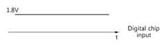
도 3(e)는 LDO의 출력단(350)에서 측정된 전압 파형을 나타낸다. LDO는 디지털 칩에서 요구하는 전압으로 배터리에서 출력된 전압을 강압할 수 있다. 예를 들면, 디지털 칩이 요구하는 전압이 1.8V이면, LDO는 배터리의 출력 전압 3.3V를 1.8V로 강압할 수 있다.3 (e) shows the voltage waveform measured at the
소스 공진기와 타겟 공진기 간의 거리에 따라 다이나믹 레인지(360)가 다이나믹 레인지(370)로 변할 수 있다. 그런데, 다이나믹 레인지(360)에서 다이나믹 레인지(370)로 변화하거나, 다이나믹 레인지(370)에서 다이나믹 레인지(360)로 변화하는 것과 같이 변화의 폭이 클수록, 레귤레이터의 동작 효율 및 배터리의 충전효율이 감소할 수 있다.The
따라서, 다이나믹 레인지의 변화의 폭이 크더라도, 레귤레이터의 입력단에서 소정의 폭을 가지는 다이나믹 레인지로 신호가 조절되면, 레귤레이터의 동작 효율 및 배터리의 충전효율이 증가할 수 있다.
Therefore, even if the dynamic range varies widely, the operation efficiency of the regulator and the charging efficiency of the battery can be increased if the signal is adjusted to a dynamic range having a predetermined width at the input terminal of the regulator.
도 4는 일실시예에 따른 무선 전력 수신 장치의 블록도이다.4 is a block diagram of a wireless power receiving apparatus according to an embodiment.
도 4를 참조하면, 무선 전력 수신 장치는 수신부(410) 및 제어부(420)를 포함할 수 있다.Referring to FIG. 4, the wireless power receiving apparatus may include a receiving
수신부(410)는 소스 공진기와 타겟 공진기 간의 상호 공진을 통하여 무선으로 전력을 수신할 수 있다.The receiving
제어부(420)는 타겟 공진기와 수동소자를 연결하여 타겟 공진기의 출력 전압의 다이나믹 레인지(dynamic range)를 제어할 수 있다. 타겟 공진기의 출력 전압은 정류기로 인가될 수 있다. 다시 표현하면, 제어부(420)는 수동소자를 이용하여 정류기의 입력 전압의 다이나믹 레인지를 제어할 수 있다.The
수동소자는 타겟 공진기에 포함된 캐패시터의 용량 이상을 가지는 제1 캐패시터일 수 있다. 수동소자는 타겟 공진기에 포함된 캐패시터 보다 작은 용량을 가지는 제2 캐패시터일 수 있다.The passive element may be a first capacitor having a capacitance equal to or greater than the capacitance of the capacitor included in the target resonator. The passive element may be a second capacitor having a smaller capacitance than the capacitor included in the target resonator.
제어부(420)는 타겟 공진기와 제1 캐패시터 및 제2 캐패시터 중 적어도 하나를 연결하여 타겟 공진기의 출력 전압의 다이나믹 레인지를 감쇄시킬 수 있다. 이때, 타겟 공진기와 제1 캐패시터 및 제2 캐패시터 중 적어도 하나는 병렬로 연결될 수 있다. 예를 들어, 타겟 공진기와 제1 캐패시터가 연결되면, 타겟 공진기에 저장된 전력이 제1 캐패시터로 전달될 수 있다. 제1 캐패시터의 용량만큼 타겟 공진기에 저장된 전력이 제1 캐패시터로 전달될 수 있다. 제1 캐패시터의 용량에 비례하여 타겟 공진기의 출력 전압의 다이나믹 레인지가 감쇄될 수 있다. 즉, 타겟 공진기의 출력 전압의 파형의 진폭이 감소할 수 있다. 타겟 공진기와 제2 캐패시터가 연결된 경우에도, 타겟 공진기에 저장된 전력이 제2 캐패시터로 전달되므로, 타겟 공진기의 출력 전압의 다이나믹 레인지가 제2 캐패시터의 용량에 비례하여 감쇄될 수 있다.The
제어부(430)는 타겟 공진기와 제2 캐패시터를 연결하여 타겟 공진기의 출력 전압의 다이나믹 레인지를 증폭시킬 수 있다. 타겟 공진기는 인덕터 및 캐패시터를 포함할 수 있다. 제어부(430)는 타겟 공진기의 캐패시터와 인덕터의 연결을 끊고, 인덕터와 제2 캐패시터를 연결할 수 있다. 예를 들면, 타겟 공진기의 캐패시터의 용량과 제2 캐패시터의 용량의 차이에 비례하여, 타겟 공진기의 출력 전압의 파형의 진폭이 증가할 수 있다.The control unit 430 may amplify the dynamic range of the output voltage of the target resonator by connecting the target resonator and the second capacitor. The target resonator may include an inductor and a capacitor. The controller 430 disconnects the capacitor of the target resonator from the inductor and connects the inductor and the second capacitor. For example, the amplitude of the waveform of the output voltage of the target resonator may increase in proportion to the difference between the capacitance of the capacitor of the target resonator and the capacitance of the second capacitor.
제어부(430)는 상호 공진 중에 타겟 공진기와 제1 캐패시터 및 제2 캐패시터를 연결한 후, 타겟 공진기에 포함된 캐패시터의 전압이 기 설정된 값 이하가 되면 타겟 공진기에 포함된 캐패시터와 타겟 공진기에 포함된 인덕터의 연결을 끊을 수 있다. 예를 들면, 상기 기 설정된 값은 0V로 설정될 수 있다.When the voltage of the capacitor included in the target resonator becomes equal to or less than a predetermined value after the target resonator is connected to the first capacitor and the second capacitor during mutual resonance, the controller 430 controls the capacitor included in the target resonator and the capacitor included in the target resonator The inductor can be disconnected. For example, the predetermined value may be set to 0V.
상호 공진 중에 타겟 공진기와 제1 캐패시터 및 제2 캐패시터가 병렬로 연결되면, 무선 전력 수신 장치에 포함된 캐패시터의 용량이 커지므로, 타겟 공진기에서 출력되는 전압의 파형의 진폭이 작아지고, 출력되는 전압의 파형의 주기는 길어질 수 있다. 제어부(430)는 타겟 공진기에 포함된 캐패시터의 전압이 최소 값을 가지는 시점에 타겟 공진기에 포함된 캐패시터와 타겟 공진기에 포함된 인덕터의 연결을 끊을 수 있다.When the target resonator, the first capacitor, and the second capacitor are connected in parallel during the mutual resonance, the capacitance of the capacitor included in the wireless power receiving apparatus becomes large, so that the amplitude of the waveform of the voltage output from the target resonator becomes small, The period of the waveform of the pulse wave can be prolonged. The control unit 430 may disconnect the capacitor included in the target resonator and the inductor included in the target resonator at the time when the voltage of the capacitor included in the target resonator has the minimum value.
그 후, 제어부(430)는 타겟 공진기와 제1 캐패시터의 연결을 끊고, 타겟 공진기와 부하를 연결하여, 타겟 공진기에 저장된 전력을 채득(capture)할 수 있다.Thereafter, the control unit 430 disconnects the first resonator and the first resonator, and connects the target resonator and the load, thereby capturing the power stored in the target resonator.
제어부(420)는 타겟 공진기에 포함된 캐패시터 이상의 용량을 가지는 제1 캐패시터 및 타겟 공진기에 포함된 캐패시터 보다 작은 용량의 제2 캐패시터 중 적어도 하나를 타겟 공진기와 연결하여 타겟 공진기의 출력 전압의 다이나믹 레인지(dynamic range)를 제어할 수 있다.The
제어부(420)는 제1 캐패시터 및 제2 캐패시터 중 적어도 하나를 타겟 공진기와 연결하여, 타겟 공진기의 공진 주파수를 변경할 수 있다.The
제어부(420)는 타이밍 제어부(421)를 포함할 수 있다.The
타이밍 제어부(421)는 제1 캐패시터 및 제2 캐패시터 중 적어도 하나를 타겟 공진기와 연결하는 타이밍을 제어할 수 있다. 제어부(420)는 정류기 및 레귤레이터와 연결될 수 있다. 레귤레이터의 입력 전압으로 제어부(420)의 현재 출력 전압보다 큰 출력 전압이 요구되는 경우, 제어부(420)는 제2 캐패시터를 타겟 공진기와 연결하여, 출력 전압의 진폭을 증폭시킬 수 있다. 반대로, 레귤레이터의 입력 전압으로 제어부(420)의 현재 출력 전압보다 작은 출력 전압이 요구되는 경우, 제어부(420)는 제1 캐패시터 및 제2 캐패시터 중 적어도 하나를 타겟 공진기와 연결하여, 출력 전압의 진폭을 감쇄시킬 수 있다.The
타이밍 제어부(421)는 타겟 공진기의 출력 전압을 감쇄시키기 위해, 제1 캐패시터 및 제2 캐패시터 중 적어도 하나를 타겟 공진기와 연결하는 타이밍을 제어할 수 있다. 예를 들면, 타이밍 제어부(421)는 타겟 공진기에 저장된 전력이 기 설정된 값 이상이 되면, 타겟 공진기와 제1 캐패시터를 연결할 수 있다. 기 설정된 값으로는 타겟 공진기에서 저장할 수 있는 전력의 최대값이 설정될 수 있다. 타겟 공진기의 출력 전압의 진폭이 감쇄 됨으로써, 출력 전압의 다이나믹 레인지가 작아질 수 있다.The
타이밍 제어부(421)는 타겟 공진기의 출력 전압을 증폭하기 위해, 제2 캐패시터를 타겟 공진기와 연결하는 타이밍을 제어할 수 있다. 타겟 공진기의 출력 전압의 진폭이 증폭함으로써, 출력 전압의 다이나믹 레인지가 커질 수 있다.The
레귤레이터는 입력 전압을 승압하는 부스터 컨버터(booster converter) 또는 입력 전압을 강압하는 벅 컨버터(buck converter)를 포함할 수 있다.The regulator may include a booster converter that boosts the input voltage or a buck converter that steps down the input voltage.
제어부(420)는 무선 전력 수신 장치의 전반적인 제어를 담당하고, 수신부(410)의 기능을 수행할 수 있다. 도 4의 실시 예에서 이를 별도로 구성하여 도시한 것은 각 기능들을 구별하여 설명하기 위함이다. 따라서 실제로 제품을 구현하는 경우에 이들 모두를 제어부(420)에서 처리하도록 구성할 수도 있으며, 이들 중 일부만을 제어부(420)에서 처리하도록 구성할 수도 있다.
The
도 5(a) 내지 도 10(c)는 다른 일실시예에 따른 무선 전력 수신 장치의 블록도 및 무선 전력 수신 장치의 동작을 나타낸 도면이다.5 (a) to 10 (c) are block diagrams of a wireless power receiving apparatus according to another embodiment and operations of a wireless power receiving apparatus.
도 5(a)는 정류기의 입력 신호의 진폭을 감쇄시키는 무선 전력 수신 장치의 구성을 나타내고, 도 5(b)는 제2 스위치부(530)의 동작에 따라 정류기의 입력 신호의 진폭의 변화를 나타낸다.5A shows a configuration of a wireless power receiving apparatus for attenuating the amplitude of an input signal of the rectifier. FIG. 5B shows a change in the amplitude of the input signal of the rectifier according to the operation of the
도 5(a)를 참조하면, 무선 전력 수신 장치는 타겟 공진기(510)의 출력 신호의 진폭을 감쇄시킬 수 있다. 무선 전력 수신 장치는 타겟 공진기(510), 제1 스위치부(520), 제2 스위치부(530) 및 제어부(540)를 기본적인 구성요소로 포함할 수 있다. 제2 스위치부(530)의 후단에 정류기, 레귤레이터(regulator), 배터리 등이 추가적으로 포함될 수 있다.Referring to FIG. 5A, the wireless power receiving apparatus can attenuate the amplitude of the output signal of the
제1 스위치부(520)는 타겟 공진기(510)와 정류기를 연결할 수 있다.The
제2 스위치부(530)는 타겟 공진기(510)와 정류기 사이에 캐패시터 CL를 타겟 공진기(510)와 병렬로 연결할 수 있다. 이때, 캐패시터 CL의 용량은 타겟 공진기(510)의 캐패시터 C2의 용량보다 크거나 같을 수도 있고, 캐패시터 C2의 용량보다 작을 수도 있다. 제어부(540)는 제1 스위치부(520) 및 제2 스위치부(530)의 동작을 제어할 수 있다.The
제2 스위치부(530)가 온(ON)된 상태에서, 제1 스위치부(520)가 온(ON)되면, 정류기에 입력되어야 할 전력의 일부가 캐패시터 CL로 분배됨으로써, 정류기에 입력되는 신호의 진폭이 감소하게 된다. 감소하는 폭은 캐패시터 CL의 용량에 따라 조절될 수 있다.When the
도 5(b)를 참조하면, 제1 스위치부(520)가 오프(OFF)인 구간에서 타겟 공진기(510)는 소스 공진기와 상호 공진을 수행할 수 있다. 상호 공진 후, 제1 스위치부(520)가 온(ON)되면, 타겟 공진기(510)와 정류기가 연결되어, 타겟 공진기(510)에 저장된 전력이 정류기 및 레귤레이터를 통과하여 배터리로 전달될 수 있다. 제2 스위치부(530)가 계속 오프(OFF)인 상태로 유지되면, 타겟 공진기(510)에서 출력된 신호는 그대로 정류기로 입력될 수 있다.Referring to FIG. 5B, the
시점(550)에서 제2 스위치부(530)가 온(ON)되면, 타겟 공진기(510)에 저장된 전력 중 일부가 캐패시터 CL을 충전시킴으로써, 정류기의 입력 신호의 진폭이 감소할 수 있다.
When the
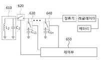
도 6(a)는 정류기의 입력 신호의 진폭을 다양한 폭으로 감쇄시키는 무선 전력 수신 장치의 구성을 나타내고, 도 6(b), 도 6(c), 도 6(d)는 제2 스위치부(630) 및 제3 스위치부(640)의 동작에 따라 정류기의 입력 신호의 진폭의 변화를 나타낸다.6 (a) shows a configuration of a wireless power receiving apparatus for attenuating the amplitude of an input signal of a rectifier with various widths, and Figs. 6 (b), 6 (c) and 6 630 and the
도 6(a)를 참조하면, 무선 전력 수신 장치는 타겟 공진기(610)의 출력 신호의 진폭을 다양한 폭으로 감쇄시킬 수 있다. 무선 전력 수신 장치는 타겟 공진기(610), 제1 스위치부(620), 제2 스위치부(630), 제3 스위치부(640) 및 제어부(650)를 기본적인 구성요소로 포함할 수 있다. 제3 스위치부(640)의 후단에 정류기, 레귤레이터, 배터리 등이 추가적으로 포함될 수 있다.6 (a), the wireless power receiving apparatus can attenuate the amplitude of the output signal of the
제1 스위치부(620)는 타겟 공진기(610)와 정류기를 연결할 수 있다.The
제2 스위치부(630)는 타겟 공진기(610)와 정류기 사이에 캐패시터 CL1를 타겟 공진기(610)와 병렬로 연결할 수 있다. 이때, 캐패시터 CL1의 용량은 타겟 공진기(610)의 캐패시터 C2의 용량보다 크거나 같을 수도 있고, 캐패시터 C2의 용량보다 작을 수도 있다.The
제3 스위치부(640)는 캐패시터 CL1와 정류기 사이에 캐패시터 CLn를 타겟 공진기(610)와 병렬로 연결할 수 있다. 캐패시터 CL1의 용량은 캐패시터 CL1의 용량보다 크거나 같을 수도 있고, 캐패시터 CL1의 용량보다 작을 수도 있다.The
제어부(650)는 제1 스위치부(620), 제2 스위치부(630) 및 제3 스위치부(640)의 동작을 제어할 수 있다.The
제2 스위치부(630)가 온(ON)된 상태에서, 제1 스위치부(620)가 온(ON)되면, 정류기에 입력되어야 할 전력의 일부가 캐패시터 CL1로 분배됨으로써, 정류기에 입력되는 신호의 진폭이 감소하게 된다. 제2 스위치부(630) 및 제3 스위치부(640)가 온(ON)된 상태에서, 제1 스위치부(620)가 온(ON)되면, 정류기에 입력되어야 할 전력의 일부가 캐패시터 CL1 및 캐패시터 CLn로 분배됨으로써, 정류기에 입력되는 신호의 진폭이 더욱 감소하게 된다. 연결되는 캐패시터의 개수에 따라 정류기에 입력되는 신호의 진폭이 조절될 수 있다.When the
도 6(b)를 참조하면, 제1 스위치부(620)가 오프(OFF)인 구간에서 타겟 공진기(610)는 소스 공진기와 상호 공진을 수행할 수 있다. 상호 공진 후, 제1 스위치부(620)가 온(ON)되면, 타겟 공진기(610)와 정류기가 연결되어, 타겟 공진기(610)에 저장된 전력이 정류기 및 레귤레이터를 통과하여 배터리로 전달될 수 있다. 제2 스위치부(630) 및 제3 스위치부(640)가 계속 오프(OFF)인 상태로 유지되면, 타겟 공진기(610)에서 출력된 신호는 그대로 정류기로 입력될 수 있다.Referring to FIG. 6 (b), the
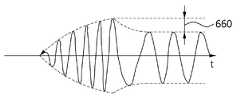
도 6(c)를 참조하면, 제2 스위치부(630)가 온(ON)된 상태에서, 제1 스위치부(620)가 온(ON)되면, 타겟 공진기(610)에 저장된 전력 중 일부가 캐패시터 CL1을 충전시킴으로써, 정류기의 입력 신호의 진폭이 폭(660)만큼 감소할 수 있다.6 (c), when the
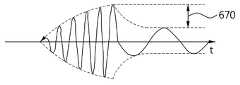
도 6(d)를 참조하면, 제2 스위치부(630) 및 제3 스위치부(640)가 온(ON)된 상태에서, 제1 스위치부(620)가 온(ON)되면, 타겟 공진기(610)에 저장된 전력 중 일부가 캐패시터 CL1 및 캐패시터 CLn을 충전시킴으로써, 정류기의 입력 신호의 진폭이 폭(670)만큼 감소할 수 있다.6 (d), when the
따라서, 타겟 공진기(610)와 병렬로 연결되는 캐패시터의 용량 또는 캐패시터의 개수에 따라 정류기의 입력 신호의 진폭이 감소할 수 있다.
Therefore, the amplitude of the input signal of the rectifier may be reduced according to the capacitance of the capacitor or the number of capacitors connected in parallel with the
도 7을 참조하면, 무선 전력 수신 장치는 타겟 공진기(710), 제1 스위치부(720), 제2 스위치부(730) 및 제3 스위치부(740)를 기본적인 구성요소로 포함할 수 있다. 제3 스위치부(740)의 후단에 정류기, 레귤레이터, 배터리 등이 추가적으로 포함될 수 있다.Referring to FIG. 7, the wireless power receiving apparatus may include a
도 6(a)와 비교해보면, 제3 스위치부(740)가 캐패시터 CLn의 후단에 위치하고 있다. 제3 스위치부(740)와 캐패시터 CL1 및 캐패시터 CLn의 위치에 따라 타겟 공진기(710)의 Q (Quality factor)가 변화될 수 있다.Compared with FIG. 6A, the
여기서, 제1 스위치부(720), 제2 스위치부(730) 및 제3 스위치부(740)의 온(ON)/오프(OFF) 동작 타이밍은 동일하다.
Here, the ON / OFF timing of the
도 8을 참조하면, 무선 전력 수신 장치는 타겟 공진기(810), 제1 스위치부(820), 제2 스위치부(830), 제3 스위치부(840) 및 디폴트 캐패시터(850)를 기본적인 구성요소로 포함할 수 있다. 디폴트 캐패시터(850)의 후단에 정류기, 레귤레이터, 배터리 등이 추가적으로 포함될 수 있다.8, a wireless power receiving apparatus includes a
도 7과 비교하여, 제1 스위치부(820) 및 제2 스위치부(830)의 온(ON)/오프(OFF) 동작 타이밍과 제3 스위치부(840)의 온(ON)/오프(OFF) 동작 타이밍은 동일할 필요가 없다.
7, the ON / OFF timing of the
도 9(a)는 정류기의 입력 신호의 진폭을 증폭시키는 무선 전력 수신 장치의 구성을 나타내고, 도 9(b) 및 도 9(c)는 제1 스위치부(920), 제2 스위치부(930) 및 제3 스위치부(940)의 동작에 따라 정류기의 입력 신호의 진폭의 변화를 나타낸다.9 (a) and 9 (b) show a configuration of a wireless power receiving apparatus for amplifying the amplitude of an input signal of a rectifier, and FIG. 9 (c) shows a configuration of a
도 9(a)를 참조하면, 무선 전력 수신 장치는 타겟 공진기(910), 제1 스위치부(920), 제2 스위치부(930) 및 제3 스위치부(940)를 기본적인 구성요소로 포함할 수 있다. 제3 스위치부(940)의 후단에 정류기, 레귤레이터, 배터리 등이 추가적으로 포함될 수 있다.9A, the wireless power receiving apparatus includes a
제2 스위치부(930)는 상호 공진 중에, 타겟 공진기(910)와 캐패시터 CL을 병렬로 연결할 수 있다. 이때, 캐패시터 CL의 용량은 타겟 공진기(910)의 캐패시터 C2의 용량보다 작은 경우를 가정한다. 제2 스위치부(930)는 타겟 공진기(910)에 저장된 전력량이 기 설정된 값 이상이 되면, 타겟 공진기(910)와 캐패시터 CL을 병렬로 연결할 수도 있다. 여기서 기 설정된 값으로는, 타겟 공진기(910)에서 저장할 수 있는 최대 전력량이 설정될 수 있다.The
제1 스위치부(920)는 타겟 공진기(910)에 포함된 캐패시터 C2의 전압이 기 설정된 값 이하가 되면, 타겟 공진기(910)에 포함된 캐패시터 C2와 타겟 공진기(910)에 포함된 인덕터 L2의 연결을 끊을 수 있다. 예를 들어, 기 설정된 값으로는 0V가 설정될 수 있다. 따라서, 제1 스위치부(920)는 타겟 공진기(910)에서 측정되는 전압 Vc가 0V이하가 되면, 캐패시터 C2와 인덕터 L2의 연결을 끊을 수 있다.A first inductor included in the
제1 스위치부(920)는 타겟 공진기(910)에 포함된 인덕터 L2의 전압이 기 설정된 값 이상이 되면, 타겟 공진기(910)에 포함된 캐패시터 C2와 타겟 공진기(910)에 포함된 인덕터 L2의 연결을 끊을 수 있다. 예를 들어, 기 설정된 값으로는 인덕터 L2에 인가될 수 있는 최대 전압값이 설정될 수 있다.When the voltage of the inductor L2 included in the
타겟 공진기(910)에 저장된 전력은 캐패시터 C2와 인덕터 L2 사이에서 자기 공진을 통해 이동할 수 있다. 타겟 공진기(910)에 저장된 전력이 인덕터 L2로 모두 이동한 경우에, 제1 스위치부(920)는 캐패시터 C2와 인덕터 L2의 연결을 끊을 수 있다.The power stored in the
캐패시터 C2와 인덕터 L2의 연결이 끊어진 결과, 인덕터 L2는 캐패시터 CL과만 연결된다.As a result of disconnecting the capacitor C2 and the inductor L2 , the inductor L2 is connected only to the capacitor CL.
캐패시터 CL의 용량은 캐패시터 C2의 용량보다 작으므로, 정류기에 입력되는 신호의 진폭이 증가하게 된다. 증가하는 폭은 캐패시터 CL의 용량에 따라 조절될 수 있다.Since the capacitance of the capacitor CL is smaller than the capacitance of the capacitor C2 , the amplitude of the signal input to the rectifier increases. The increasing width can be adjusted according to the capacity of the capacitor CL.
제3 스위치부(940)는 타겟 공진기(910)와 캐패시터 CL이 병렬로 연결된 이후에, 캐패시터 CL와 정류기를 연결할 수 있다.The
도 9(b)를 참조하면, 제1 스위치부(920)가 온(ON)인 구간에서 타겟 공진기(910)는 소스 공진기와 상호 공진을 수행할 수 있다. 제2 스위치부(930)가 온(ON)되어 타겟 공진기(910)와 캐패시터 CL이 연결되면, 타겟 공진기(910)의 공진 주파수가 변경될 수 있다. 공진 주파수가 변경된 후, 타겟 공진기(910)에 포함된 캐패시터 C2에서 측정되는 전압 Vc가 최소가 되는 시점에서, 제1 스위치부(920)는 오프(OFF)될 수 있다. 이후, 제3 스위치부(940)가 온(ON)되면, 타겟 공진기(910)와 정류기가 연결되어, 타겟 공진기(910)에 저장된 전력이 정류기 및 레귤레이터를 통과하여 배터리로 전달될 수 있다.Referring to FIG. 9B, the
제2 스위치부(930)가 온(ON)되고, 제1 스위치부(920)가 오프(OFF)되면, 정류기에 입력되는 신호의 진폭은 폭(950)만큼 증폭될 수 있다. 이때, 폭(950)은 캐패시터 C2의 용량과 캐패시터 CL의 용량 차에 따라 결정될 수 있다. 용량의 차이가 커질수록, 폭(950)도 커질 수 있다.The
증폭된 신호는 제3 스위치부(930)가 온(ON)되면, 정류기 및 레귤레이터에서 변환된 후 배터리로 전달될 수 있다.When the
도 9(c)의 경우는, 캐패시터 C2와 캐패시터 CL이 인덕터 L2와 병렬로 연결된 상태에서 상호 공진이 발생하는 경우의 제1 스위치부(920), 제2 스위치부(930) 및 제3 스위치부(940)의 동작을 나타낸 것이다. 예를 들면, 도 9(b)의 경우는 캐패시터 C2가 1nF이고, 도 9(c)의 경우는 캐패시터 C2가 0.5nF, 캐패시터 CL이 0.5nF인 경우이다.9 (c), the
도 9(c)를 참조하면, 제1 스위치부(920) 및 제2 스위치부(930)가 온(ON)인 구간에서 타겟 공진기(910)는 소스 공진기와 상호 공진을 수행할 수 있다.Referring to FIG. 9C, the
상호 공진 결과, 타겟 공진기(910)에 포함된 캐패시터 C2에서 측정되는 전압 Vc가 최소가 되는 시점에서, 제1 스위치부(920)는 오프(OFF)될 수 있다. 제1 스위치부(920)가 오프(OFF)되면, 캐패시터 C2의 연결이 끊어지게 되어 타겟 공진기(910)의 공진 주파수가 변경될 수 있다. 제1 스위치부(920)가 오프(OFF)되면, 타겟 공진기(910)에 포함된 인덕터 L2는 캐패시터 CL과만 연결된다. 이후, 제3 스위치부(940)가 온(ON)되면, 타겟 공진기(910)와 정류기가 연결되어, 타겟 공진기(910)에 저장된 전력이 정류기 및 레귤레이터를 통과하여 배터리로 전달될 수 있다.As a result of the mutual resonance, the
제1 스위치부(920)가 오프(OFF)되면, 정류기에 입력되는 신호의 진폭은 증폭될 수 있다. 증폭 량은 캐패시터 C2의 용량과 캐패시터 CL의 용량 차이에 기초하여 결정될 수 있다. 증폭된 신호는 제3 스위치부(930)가 온(ON)되면, 정류기 및 레귤레이터에서 변환된 후 배터리로 전달될 수 있다.
When the
도 10(a)는 정류기의 입력 신호의 진폭을 감쇄 및 증폭시켜 전력의 채득시점을 조절하는 무선 전력 수신 장치의 구성을 나타내고, 도 10(b) 및 도 10(c)는 제1 스위치부(1020), 제2 스위치부(1030), 제3 스위치부(1040) 및 제4 스위치부(1050)의 동작에 따라 정류기의 입력 신호의 진폭의 변화를 나타낸다. 높은 공진 주파수를 가지는 경우 제4 스위치부(1050)를 정확히 원하는 시점에 온(ON)하는 것은 쉬운 일이 아니다.10 (a) and 10 (b) show a configuration of a wireless power receiving apparatus for adjusting the time of power acquisition by attenuating and amplifying the amplitude of an input signal of a rectifier, and FIGS. 10 (b) 1020, the
도 10(a)의 구조는 타겟 공진기(1010)와 병렬로 연결된 캐패시터 C2보다 용량이 큰 캐패시터 CLarge와 작은 캐패시터 CSmall을 사용하여 제4 스위치부(1050)의 동작 타이밍의 정교성에 대한 부담을 줄여줄 수 있다.Figure 10 (a) structure of the load on the sophistication of the operation timing of the target cavity (1010) and by the parallel capacitance than the capacitor C2 connected to the use of a large capacitor CLarge and small capacitor CSmall the
도 10(a)를 참조하면, 무선 전력 수신 장치는 타겟 공진기(1010), 제1 스위치부(1020), 제2 스위치부(1030), 제3 스위치부(1040) 및 제4 스위치부(1050)를 기본적인 구성요소로 포함할 수 있다. 제4 스위치부(1050)의 후단에 정류기, 레귤레이터, 배터리 등이 추가적으로 포함될 수 있다.10A, the wireless power receiving apparatus includes a
제2 스위치부(1030)는 타겟 공진기(1010)가 상호 공진하는 동안 타겟 공진기(1010)와 캐패시터 CLarge을 병렬로 연결할 수 있다. 이때, 캐패시터 CLarge의 용량은 타겟 공진기(1010)의 캐패시터 C2의 용량보다 크거나 같은 경우를 가정한다.The
제3 스위치부(1040)는 타겟 공진기(1010)가 상호 공진하는 동안 타겟 공진기(1010)와 캐패시터 CSmall을 병렬로 연결할 수 있다. 이때, 캐패시터 CSmall의 용량은 타겟 공진기(1010)의 캐패시터 C2의 용량보다 작은 경우를 가정한다. 제3 스위치부(1040)는 제2 스위치부(1030)와 동일한 타이밍으로 타겟 공진기(1010)와 캐패시터 CSmall을 병렬로 연결할 수도 있다.The
캐패시터 CLarge와 캐패시터 CSmall이 타겟 공진기(1010)와 연결되면, 타겟 공진기(1010)의 공진 주파수가 변경될 수 있다. 또한, 캐패시터 CLarge와 캐패시터 CSmall의 연결로, 순간, 타겟 공진기(1010)의 상호 공진 주기가 길어질 수 있다. 상호 공진 주기가 길어짐으로써, 공진 주파수가 작아지게 되고, 제4 스위치부(1050)를 온(ON)시킬 수 있는 타이밍이 길게 확보될 수 있다.When the capacitor Clarge and the capacitor Csmall are connected to the
제1 스위치부(1020)는 타겟 공진기(1010)에 포함된 캐패시터 C2의 전압이 기 설정된 값 이하가 되면, 타겟 공진기(1010)에 포함된 캐패시터 C2와 타겟 공진기(1010)에 포함된 인덕터 L2의 연결을 끊을 수 있다. 예를 들어, 기 설정된 값으로는 0V가 설정될 수 있다. 따라서, 제1 스위치부(920)는 타겟 공진기(910)에서 측정되는 전압 Vc가 0V이하가 되면, 캐패시터 C2와 인덕터 L2의 연결을 끊을 수 있다.The first inductor includes a
제1 스위치부(1020)는 타겟 공진기(1010)에 포함된 인덕터 L2의 전압이 기 설정된 값 이상이 되면, 타겟 공진기(1010)에 포함된 캐패시터 C2와 타겟 공진기(1010)에 포함된 인덕터 L2의 연결을 끊을 수 있다. 예를 들어, 기 설정된 값으로는 인덕터 L2에 인가될 수 있는 최대 전압값이 설정될 수 있다.When the voltage of the inductor L2 included in the
타겟 공진기(1010)에 저장된 전력은 캐패시터 C2와 인덕터 L2 사이에서 자기 공진을 통해 이동할 수 있다. 타겟 공진기(1010)에 저장된 전력이 인덕터 L2로 모두 이동한 경우에, 제1 스위치부(1020)는 캐패시터 C2와 인덕터 L2의 연결을 끊을 수 있다.The power stored in the
제2 스위치부(1030)는 타겟 공진기(1010)에 포함된 캐패시터 C2의 전압이 기 설정된 값 이하가 되면, 캐패시터 CLarge의 연결을 끊을 수 있다. 제2 스위치부(1030)는 제1 스위치부(1020)가 오프(OFF)되는 시점과 동일한 시점에 오프(OFF)될 수 있다.The
캐패시터 C2 및 캐패시터 CLarge와 인덕터 L2의 연결이 끊어진 결과, 인덕터 L2는 캐패시터 CSmall과만 연결될 수 있다.As a result of the disconnection between the capacitor C2 and the capacitor Clarge and the inductor L2 , the inductor L2 can be connected only to the capacitor CSmall .
캐패시터 CSmall의 용량은 캐패시터 C2의 용량보다 작으므로, 정류기에 입력되는 신호의 진폭이 증가하게 된다. 증가하는 폭은 캐패시터 CSmall의 용량에 따라 조절될 수 있다.Since the capacitance of the capacitor CSmall is smaller than the capacitance of the capacitor C2 , the amplitude of the signal input to the rectifier increases. The increasing width can be adjusted according to the capacitance of the capacitor CSmall .
제4 스위치부(1050)가 온(ON)되면, 타겟 공진기(1010)에 저장된 전력이 정류기 및 레귤레이터를 통하여 배터리로 전달될 수 있다.When the
도 10(b)를 참조하면, 제1 스위치부(1020)가 온(ON)이고, 제2 스위치부(1030) 및 제3 스위치부(1040)가 오프(OFF)인 구간에서 타겟 공진기(1010)는 소스 공진기와 상호 공진을 수행할 수 있다.10B, when the
제2 스위치부(1030) 및 제3 스위치부(1040)가 온(ON)되어 타겟 공진기(1010)와 캐패시터 CLarge와 캐패시터 CSmall이 연결되면, 타겟 공진기(1010)의 공진 주파수가 변경될 수 있다. 제2 스위치부(1030) 및 제3 스위치부(1040)는 타겟 공진기(1010)가 상호 공진 중인 시점(1060)에 온(ON)될 수 있다. 캐패시터 CLarge와 캐패시터 CSmall의 연결로, 타겟 공진기(1010)의 공진 주파수가 작아지게 되고, 블록(1080) 내부의 모양과 같이 공진 주기는 길어질 수 있다.When the
타겟 공진기(1010)에 포함된 캐패시터 C2에서 측정되는 전압 Vc가 최소가 되는 시점(1070)에서, 제1 스위치부(1020)는 오프(OFF)될 수 있다. 제1 스위치부(1020)가 오프(OFF)되면, 인덕터 L2와 캐패시터 C2의 연결이 끊어질 수 있다.The
타겟 공진기(1010)에 포함된 캐패시터 C2에서 측정되는 전압 Vc가 최소가 되는 시점(1070)에서, 제1 스위치부(1020) 및 제2 스위치부(1030)가 오프(OFF)되면, 타겟 공진기(1010)의 출력 신호의 진폭이 증폭될 수 있다. 제2 스위치부(1020)가 오프(OFF)되면, 인덕터 L2와 캐패시터 CLarge의 연결이 끊어질 수 있다. 결과적으로 인덕터 L2와 캐패시터 CSmall만 연결된 상태가 된다.When the
타겟 공진기(1010)에 포함된 캐패시터 C2에서 측정되는 전압 Vc가 최소가 되는 시점(1070)에서, 제4 스위치부(1050)가 온(ON)되면, 타겟 공진기(1010)와 정류기가 연결되어, 타겟 공진기(1010)에 저장된 전력이 정류기 및 레귤레이터를 통과하여 배터리로 전달될 수 있다.The
도 10(c)의 경우는, 캐패시터 C2와 캐패시터 CSmall이 인덕터 L2와 병렬로 연결된 상태에서 상호 공진이 발생하는 경우의 제1 스위치부(1020), 제2 스위치부(1030), 제3 스위치부(1040) 및 제4 스위치부(1050)의 동작을 나타낸 것이다. 예를 들면, 도 10(b)의 경우는 캐패시터 C2가 1nF이고, 도 10(c)의 경우는 캐패시터 C2가 0.5nF, 캐패시터 CSmall이 0.5nF인 경우이다.10C, the
도 10(c)를 참조하면, 제1 스위치부(1020) 및 제3 스위치부(1040)가 온(ON)인 구간에서 타겟 공진기(1010)는 소스 공진기와 상호 공진을 수행할 수 있다.Referring to FIG. 10C, the
제2 스위치부(1030)가 온(ON)되어 타겟 공진기(1010)와 캐패시터 CLarge이 연결되면, 타겟 공진기(1010)의 공진 주파수가 변경될 수 있다. 제2 스위치부(1030)는 타겟 공진기(1010)가 상호 공진 중인 시점(1080)에 온(ON)될 수 있다. 캐패시터 CLarge의 연결로, 타겟 공진기(1010)의 공진 주파수가 작아지게 되고, 공진 주기는 길어질 수 있다.The resonance frequency of the
타겟 공진기(1010)에 포함된 캐패시터 C2에서 측정되는 전압 Vc가 최소가 되는 시점(1090)에서, 제1 스위치부(1020)가 오프(OFF)되면, 인덕터 L2와 캐패시터 C2의 연결이 끊어지고, 제2 스위치부(1020)가 오프(OFF)되면, 인덕터 L2와 캐패시터 CLarge의 연결이 끊어질 수 있다. 따라서, 제1 스위치부(1020) 및 제2 스위치부(1030)가 오프(OFF)되면, 인덕터 L2와 캐패시터 CSmall만 연결된 상태가 된다.When the
캐패시터의 용량이 캐패시터 C2 및 캐패시터 Csmall에서 캐패시터 CLarge만큼 추가되었다가, 캐패시터 Csmall로 감소함으로써, 타겟 공진기(1010)의 출력 신호의 진폭이 증폭될 수 있다.The capacitance of the capacitor C2 is added to the capacitor Clarge in the capacitor C2 and the capacitor Csmall is reduced to the capacitor Csmall so that the amplitude of the output signal of the
이후, 제4 스위치부(1050)가 온(ON)되면, 타겟 공진기(1010)와 정류기가 연결되어, 타겟 공진기(1010)에 저장된 전력이 정류기 및 레귤레이터를 통과하여 배터리로 전달될 수 있다.
When the
도 11은 일실시예에 따른 무선 전력 수신 방법의 흐름도이다.11 is a flow diagram of a wireless power receiving method in accordance with an embodiment.
1110단계에서, 무선 전력 수신 장치는 소스 공진기와 타겟 공진기 간의 상호 공진을 통하여 무선으로 전력을 수신할 수 있다.In
1120단계에서, 무선 전력 수신 장치는 타겟 공진기에 포함된 캐패시터 이상의 용량을 가지는 제1 캐패시터 및 타겟 공진기에 포함된 캐패시터 보다 작은 용량의 제2 캐패시터 중 적어도 하나를 타겟 공진기와 연결하여 타겟 공진기의 출력 전압의 다이나믹 레인지(dynamic range)를 제어할 수 있다. 타겟 공진기의 출력 전압은 타겟 공진기의 후단에 연결되는 정류기의 입력 전압과 동일한 크기를 가질 수 있다.In
일 측면에 있어서, 무선 전력 수신 장치는 상기 타겟 공진기의 출력 전압을 감쇄시키기 위해, 제1 캐패시터 및 제2 캐패시터 중 적어도 하나를 타겟 공진기와 연결하는 타이밍을 제어할 수 있다.In one aspect, the wireless power receiving apparatus can control the timing of connecting at least one of the first capacitor and the second capacitor with the target resonator in order to attenuate the output voltage of the target resonator.
일 측면에 있어서, 무선 전력 수신 장치는 타겟 공진기의 출력 전압을 증폭하기 위해, 제2 캐패시터를 타겟 공진기와 연결하는 타이밍을 제어할 수 있다.In one aspect, the wireless power receiving apparatus can control the timing of connecting the second capacitor with the target resonator in order to amplify the output voltage of the target resonator.
일 실시 예에 따른 무선 전력 수신 장치는 수동 소자를 이용하여 무선 전력 전송 장치 또는 무선 전력 수신 장치의 모빌리티(mobility)로 인하여 큰 다이나믹 레인지(dynamic range)를 가지는 수신 신호의 진폭을 증폭 또는 감쇄 시킴으로써, 충전 효율 및 신호 변환 효율을 증가시킬 수 있다.A wireless power receiving apparatus according to an embodiment amplifies or attenuates the amplitude of a received signal having a large dynamic range due to the mobility of a wireless power transmission apparatus or a wireless power receiving apparatus by using a passive element, The charging efficiency and the signal conversion efficiency can be increased.
또한, 일 실시 예에 따른 무선 전력 수신 장치는 수동 소자를 이용하여 다이나믹 레인지를 조절함으로써, 배터리 또는 디지털 칩에 안정적으로 전력을 공급할 수 있다.In addition, the wireless power receiving apparatus according to an exemplary embodiment can stably supply power to a battery or a digital chip by adjusting a dynamic range using a passive element.
또한, 일 실시 예에 따른 무선 전력 수신 장치는 타겟 공진기의 캐패시터보다 작은 용량의 캐패시터와 큰 용량의 캐패시터를 상기 타겟 공진기와 연결하는 타이밍을 조절함으로써, 상기 타겟 공진기에 저장된 전력을 효율적으로 채득할 수 있다.In addition, the wireless power receiving apparatus according to an embodiment can adjust the timing of connecting a capacitor having a capacitance smaller than that of the capacitor of the target resonator and a capacitor having a larger capacitance to the target resonator, so that the power stored in the target resonator can be efficiently have.
실시예에 따른 방법은 다양한 컴퓨터 수단을 통하여 실행될 수 있는 프로그램 명령 형태로 구현되어 컴퓨터 판독 가능 매체에 기록될 수 있다. 상기 컴퓨터 판독 가능 매체는 프로그램 명령, 데이터 파일, 데이터 구조 등을 단독으로 또는 조합하여 포함할 수 있다. 상기 매체에 기록되는 프로그램 명령은 실시예를 위하여 특별히 설계되고 구성된 것들이거나 컴퓨터 소프트웨어 당업자에게 공지되어 사용 가능한 것일 수도 있다. 컴퓨터 판독 가능 기록 매체의 예에는 하드 디스크, 플로피 디스크 및 자기 테이프와 같은 자기 매체(magnetic media), CD-ROM, DVD와 같은 광기록 매체(optical media), 플롭티컬 디스크(floptical disk)와 같은 자기-광 매체(magneto-optical media), 및 롬(ROM), 램(RAM), 플래시 메모리 등과 같은 프로그램 명령을 저장하고 실행하도록 특별히 구성된 하드웨어 장치가 포함된다. 프로그램 명령의 예에는 컴파일러에 의해 만들어지는 것과 같은 기계어 코드뿐만 아니라 인터프리터 등을 사용해서 컴퓨터에 의해서 실행될 수 있는 고급 언어 코드를 포함한다. 상기된 하드웨어 장치는 실시예의 동작을 수행하기 위해 하나 이상의 소프트웨어 모듈로서 작동하도록 구성될 수 있으며, 그 역도 마찬가지이다.The method according to an embodiment may be implemented in the form of program instructions that can be executed through various computer means and recorded on a computer readable medium. The computer-readable medium may include program instructions, data files, data structures, and the like, alone or in combination. The program instructions to be recorded on the medium may be those specially designed and configured for the embodiments or may be available to those skilled in the art of computer software. Examples of computer-readable media include magnetic media such as hard disks, floppy disks and magnetic tape; optical media such as CD-ROMs and DVDs; magnetic media such as floppy disks; Magneto-optical media, and hardware devices specifically configured to store and execute program instructions, such as ROM, RAM, flash memory, and the like. Examples of program instructions include machine language code such as those produced by a compiler, as well as high-level language code that can be executed by a computer using an interpreter or the like. The hardware devices described above may be configured to operate as one or more software modules to perform the operations of the embodiments, and vice versa.
이상과 같이 실시예들이 비록 한정된 실시예와 도면에 의해 설명되었으나, 해당 기술분야에서 통상의 지식을 가진 자라면 상기의 기재로부터 다양한 수정 및 변형이 가능하다. 예를 들어, 설명된 기술들이 설명된 방법과 다른 순서로 수행되거나, 및/또는 설명된 시스템, 구조, 장치, 회로 등의 구성요소들이 설명된 방법과 다른 형태로 결합 또는 조합되거나, 다른 구성요소 또는 균등물에 의하여 대치되거나 치환되더라도 적절한 결과가 달성될 수 있다.While the present invention has been particularly shown and described with reference to exemplary embodiments thereof, it is to be understood that the invention is not limited to the disclosed exemplary embodiments. For example, it is to be understood that the techniques described may be performed in a different order than the described methods, and / or that components of the described systems, structures, devices, circuits, Lt; / RTI > or equivalents, even if it is replaced or replaced.
그러므로, 다른 구현들, 다른 실시예들 및 특허청구범위와 균등한 것들도 후술하는 특허청구범위의 범위에 속한다.Therefore, other implementations, other embodiments, and equivalents to the claims are also within the scope of the following claims.
Claims (20)
Translated fromKorean제1 캐패시터 및 제2 캐패시터 중 적어도 하나와 상기 타겟 공진기 사이의 전기적 연결을 제어하고 정류기와 상기 타겟 공진기 사이의 전기적 연결을 제어하는 제어부
를 포함하고,
상기 타겟 공진기가 상기 제1 캐패시터 및 제2 캐패시터 중 적어도 하나와 연결되고 상기 정류기와 연결되는 경우, 상기 정류기의 입력 전압은 조절되는, 무선 전력 수신 장치.A receiver for wirelessly receiving power through mutual resonance between the source resonator and the target resonator; And
A control unit for controlling an electrical connection between at least one of the first capacitor and the second capacitor and the target resonator and controlling an electrical connection between the rectifier and the target resonator,
Lt; / RTI >
Wherein the input voltage of the rectifier is adjusted when the target resonator is connected to at least one of the first capacitor and the second capacitor and is connected to the rectifier.
상기 제어부는
상기 제1 캐패시터 및 상기 제2 캐패시터 중 적어도 하나를 상기 타겟 공진기와 연결하여, 상기 타겟 공진기의 공진 주파수를 변경하는
무선 전력 수신 장치.The method according to claim 1,
The control unit
Wherein at least one of the first capacitor and the second capacitor is connected to the target resonator to change a resonant frequency of the target resonator
Wireless power receiving device.
상기 제어부는
상기 제1 캐패시터 및 상기 제2 캐패시터 중 적어도 하나를 상기 타겟 공진기와 연결하는 타이밍을 제어하는 타이밍 제어부
를 포함하는 무선 전력 수신 장치.The method according to claim 1,
The control unit
A timing controller for controlling a timing of connecting at least one of the first capacitor and the second capacitor to the target resonator,
And the wireless power receiving device.
상기 타이밍 제어부는
상기 타겟 공진기의 출력 전압을 감쇄시키기 위해, 상기 제1 캐패시터 및 상기 제2 캐패시터 중 적어도 하나를 상기 타겟 공진기와 연결하는 타이밍을 제어하고,
상기 타겟 공진기의 출력 전압을 증폭하기 위해, 상기 제2 캐패시터를 상기 타겟 공진기와 연결하는 타이밍을 제어하는
무선 전력 수신 장치.The method of claim 3,
The timing control unit
Controlling a timing at which at least one of the first capacitor and the second capacitor is connected to the target resonator so as to attenuate the output voltage of the target resonator,
Controlling the timing of connecting the second capacitor to the target resonator to amplify the output voltage of the target resonator
Wireless power receiving device.
상기 타겟 공진기와 부하를 연결하는 제1 스위치부; 및
상기 타겟 공진기와 상기 부하 사이에 상기 제1 캐패시터 및 상기 제2 캐패시터 중 적어도 하나를 병렬로 연결하는 제2 스위치부
를 더 포함하는 무선 전력 수신 장치.The method according to claim 1,
A first switch unit connecting the target resonator and the load; And
And a second switch part for connecting at least one of the first capacitor and the second capacitor in parallel between the target resonator and the load,
Further comprising:
상기 타겟 공진기와 부하를 연결하는 제1 스위치부;
상기 타겟 공진기와 상기 부하 사이에 상기 제1 캐패시터 및 상기 제2 캐패시터 중 적어도 하나를 병렬로 연결하는 제2 스위치부; 및
상기 타겟 공진기와 상기 부하 사이에 병렬로 연결된 상기 제1 캐패시터 및 상기 제2 캐패시터 중 적어도 하나와 상기 부하 사이에 제3 캐패시터를 병렬로 연결하는 제3 스위치부
를 더 포함하는 무선 전력 수신 장치.The method according to claim 1,
A first switch unit connecting the target resonator and the load;
A second switch part for connecting at least one of the first capacitor and the second capacitor in parallel between the target resonator and the load; And
A third capacitor connected in parallel between the target resonator and the load, and a third capacitor connected in parallel between at least one of the first and second capacitors and the load,
Further comprising:
상기 제1 스위치부는
상기 제3 캐패시터와 상기 부하 사이에서 상기 타겟 공진기와 상기 부하를 연결하는
무선 전력 수신 장치.The method according to claim 6,
The first switch unit
A second capacitor connected between the third capacitor and the load,
Wireless power receiving device.
상기 제1 스위치부와 상기 부하 사이에 위치하여, 상기 타겟 공진기의 공진 주파수를 변경하는 디폴트 캐패시터
를 더 포함하는 무선 전력 수신 장치.8. The method of claim 7,
And a capacitor connected between the first switch unit and the load for changing the resonant frequency of the target resonator,
Further comprising:
상기 타겟 공진기에 포함된 캐패시터의 전압이 기 설정된 값 이하가 되면, 상기 타겟 공진기에 포함된 캐패시터와 상기 타겟 공진기에 포함된 인덕터의 연결을 끊는 제1 스위치부;
상기 타겟 공진기의 공진 주파수를 변경시키기 위해 상기 타겟 공진기와 제2 캐패시터를 병렬로 연결하는 제2 스위치부; 및
상기 타겟 공진기에 포함된 캐패시터와 상기 타겟 공진기에 포함된 인덕터의 연결이 끊어진 후에, 상기 제2 캐패시터와 부하를 연결하는 제3 스위치부
를 더 포함하는 무선 전력 수신 장치.The method according to claim 1,
A first switch unit for disconnecting a capacitor included in the target resonator and an inductor included in the target resonator when the voltage of the capacitor included in the target resonator becomes a predetermined value or less;
A second switch unit for connecting the target resonator and the second capacitor in parallel to change the resonant frequency of the target resonator; And
A third switch connected between the second capacitor and the load after the capacitor included in the target resonator is disconnected from the inductor included in the target resonator,
Further comprising:
상기 타겟 공진기에 포함된 캐패시터와 상기 제2 캐패시터가 병렬로 연결되고, 상기 제2 캐패시터와 상기 부하가 연결되지 않은 상태에서, 상기 상호 공진이 발생하고, 상기 타겟 공진기에 포함된 캐패시터의 전압이 기 설정된 값 이하가 되면,
상기 제1 스위치부는 상기 타겟 공진기에 포함된 캐패시터와 상기 타겟 공진기에 포함된 인덕터의 연결을 끊고,
상기 제3 스위치부는 상기 제2 캐패시터와 상기 부하를 연결하는
무선 전력 수신 장치.10. The method of claim 9,
Wherein the mutual resonance occurs in a state in which the capacitor included in the target resonator and the second capacitor are connected in parallel and the second capacitor and the load are not connected to each other and the voltage of the capacitor included in the target resonator is When the value becomes less than the set value,
The first switch unit disconnects the capacitor included in the target resonator and the inductor included in the target resonator,
And the third switch unit connects the second capacitor and the load
Wireless power receiving device.
상기 상호 공진 중에 상기 제1 캐패시터를 상기 타겟 공진기와 병렬로 연결하고, 상기 타겟 공진기에 포함된 캐패시터의 전압이 기 설정된 값 이하가 되면, 상기 제1 캐패시터와 상기 타겟 공진기의 연결을 끊는 제1 스위치부;
상기 상호 공진 중에 상기 제2 캐패시터를 상기 타겟 공진기와 병렬로 연결하는 제2 스위치부;
상기 타겟 공진기에 포함된 캐패시터의 전압이 기 설정된 값 이하가 되면, 상기 타겟 공진기에 포함된 캐패시터와 상기 타겟 공진기에 포함된 인덕터의 연결을 끊는 제3 스위치부; 및
상기 제1 캐패시터와 상기 타겟 공진기의 연결이 끊어진 후에, 상기 제2 캐패시터와 부하를 연결하는 제4 스위치부
를 더 포함하는 무선 전력 수신 장치.The method according to claim 1,
A first capacitor connected in parallel with the target resonator during the mutual resonance and a first switch for disconnecting the first capacitor from the target resonator when the voltage of the capacitor included in the target resonator becomes a predetermined value or less, part;
A second switch for connecting the second capacitor in parallel with the target resonator during the mutual resonance;
A third switch unit for disconnecting a capacitor included in the target resonator and an inductor included in the target resonator when the voltage of the capacitor included in the target resonator becomes a predetermined value or less; And
And a fourth switch part for connecting the second capacitor to the load after the connection between the first capacitor and the target resonator is broken,
Further comprising:
상기 타겟 공진기에 포함된 캐패시터와 상기 제2 캐패시터가 병렬로 연결되고, 상기 제2 캐패시터와 상기 부하가 연결되지 않은 상태에서, 상기 상호 공진이 발생하면,
상기 제1 스위치부는 상기 상호 공진 중에 상기 제1 캐패시터를 상기 타겟 공진기와 병렬로 연결하고, 상기 타겟 공진기에 포함된 캐패시터의 전압이 기 설정된 값 이하가 되면, 상기 제1 캐패시터와 상기 타겟 공진기의 연결을 끊고,
상기 제3 스위치부는 상기 타겟 공진기에 포함된 캐패시터의 전압이 기 설정된 값 이하가 되면, 상기 타겟 공진기에 포함된 캐패시터와 상기 타겟 공진기에 포함된 인덕터의 연결을 끊고,
상기 제4 스위치부는 상기 제1 캐패시터와 상기 타겟 공진기의 연결이 끊어진 후에, 상기 제2 캐패시터와 부하를 연결하는
무선 전력 수신 장치.12. The method of claim 11,
Wherein when the mutual resonance occurs in a state where the capacitor included in the target resonator and the second capacitor are connected in parallel and the second capacitor and the load are not connected,
Wherein the first switch unit connects the first capacitor in parallel with the target resonator during the mutual resonance, and when the voltage of the capacitor included in the target resonator becomes a predetermined value or less, And,
The third switch unit disconnects the capacitor included in the target resonator and the inductor included in the target resonator when the voltage of the capacitor included in the target resonator becomes a predetermined value or less,
Wherein the fourth switch unit is connected between the second capacitor and the load after the first capacitor is disconnected from the target resonator
Wireless power receiving device.
상기 타겟 공진기와 수동소자 사이의 전기적 연결을 제어하고, 정류기와 상기 타겟 공진기 사이의 전기적 연결을 제어하는 제어부
를 포함하고,
상기 타겟 공진기가 상기 수동소자 및 상기 정류기와 연결되는 경우, 상기 정류기의 입력 전압은 조절되는, 무선 전력 수신 장치.A receiver for wirelessly receiving power through mutual resonance between the source resonator and the target resonator; And
A control unit for controlling an electrical connection between the target resonator and the passive element and controlling an electrical connection between the rectifier and the target resonator,
Lt; / RTI >
Wherein the input voltage of the rectifier is adjusted when the target resonator is connected to the passive element and the rectifier.
상기 수동소자는
상기 타겟 공진기에 포함된 캐패시터의 용량 이상을 가지는 제1 캐패시터 및 상기 타겟 공진기에 포함된 캐패시터 보다 작은 용량을 가지는 제2 캐패시터 중 적어도 하나를 포함하는
무선 전력 수신 장치.14. The method of claim 13,
The passive element
And a second capacitor having a capacitance smaller than that of the capacitor included in the target resonator, wherein the first capacitor includes a first capacitor having a capacity greater than that of the capacitor included in the target resonator,
Wireless power receiving device.
상기 제어부는
상기 타겟 공진기와 상기 제1 캐패시터 및 상기 제2 캐패시터 중 적어도 하나를 연결하여 상기 타겟 공진기의 출력 전압의 다이나믹 레인지를 감쇄시키는
무선 전력 수신 장치.15. The method of claim 14,
The control unit
And at least one of the first capacitor and the second capacitor is connected to the target resonator to attenuate the dynamic range of the output voltage of the target resonator
Wireless power receiving device.
상기 제어부는
상기 타겟 공진기와 상기 제2 캐패시터를 연결하여 상기 상기 타겟 공진기의 출력 전압의 다이나믹 레인지를 증폭시키는
무선 전력 수신 장치.15. The method of claim 14,
The control unit
The target resonator and the second capacitor are connected to amplify the dynamic range of the output voltage of the target resonator
Wireless power receiving device.
상기 제어부는
상기 상호 공진 중에 상기 타겟 공진기와 상기 제1 캐패시터 및 상기 제2 캐패시터를 연결한 후, 상기 타겟 공진기에 포함된 캐패시터의 전압이 기 설정된 값 이하가 되면,
상기 타겟 공진기에 포함된 캐패시터와 상기 타겟 공진기에 포함된 인덕터의 연결을 끊고, 상기 타겟 공진기와 상기 제1 캐패시터의 연결을 끊으며, 상기 타겟 공진기와 부하를 연결하여, 상기 타겟 공진기에 저장된 전력을 채득하는
무선 전력 수신 장치.15. The method of claim 14,
The control unit
Wherein when the voltage of the capacitor included in the target resonator becomes less than a predetermined value after connecting the target resonator to the first capacitor and the second capacitor during the mutual resonance,
Disconnecting the capacitor included in the target resonator and the inductor included in the target resonator and disconnecting the target resonator and the first capacitor to connect the target resonator and the load, Acquiring
Wireless power receiving device.
제1 캐패시터 및 제2 캐패시터 중 적어도 하나와 상기 타겟 공진기 사이의 전기적 연결을 제어하고, 정류기와 상기 타겟 공진기 사이의 전기적 연결을 제어하는 단계
를 포함하고,
상기 타겟 공진기가 상기 제1 캐패시터 및 제2 캐패시터 중 적어도 하나와 연결되고 상기 정류기와 연결되는 경우, 상기 정류기의 입력 전압은 조절되는, 무선 전력 수신 방법.Receiving power wirelessly through mutual resonance between a source resonator and a target resonator; And
Controlling an electrical connection between at least one of the first capacitor and the second capacitor and the target resonator, and controlling an electrical connection between the rectifier and the target resonator
Lt; / RTI >
Wherein the input voltage of the rectifier is regulated when the target resonator is coupled to at least one of the first capacitor and the second capacitor and is connected to the rectifier.
상기 제어하는 단계는
상기 타겟 공진기의 출력 전압을 감쇄시키기 위해, 상기 제1 캐패시터 및 상기 제2 캐패시터 중 적어도 하나를 상기 타겟 공진기와 연결하는 타이밍을 제어하는 단계; 및
상기 타겟 공진기의 출력 전압을 증폭하기 위해, 상기 제2 캐패시터를 상기 타겟 공진기와 연결하는 타이밍을 제어하는 단계
를 포함하는 무선 전력 수신 방법.19. The method of claim 18,
The step of controlling
Controlling a timing of connecting at least one of the first capacitor and the second capacitor with the target resonator to attenuate an output voltage of the target resonator; And
Controlling the timing of connecting the second capacitor to the target resonator to amplify the output voltage of the target resonator
/ RTI >
상기 제1 캐패시터는 상기 타겟 공진기에 포함된 캐패시터 이상의 용량을 갖고, 상기 제2 캐패시터는 상기 타겟 공진기에 포함된 캐패시터보다 적은 용량을 갖는, 무선 전력 수신 장치.
The method according to claim 1,
Wherein the first capacitor has a capacitance larger than that of the capacitor included in the target resonator, and the second capacitor has a smaller capacitance than the capacitor included in the target resonator.
Priority Applications (2)
| Application Number | Priority Date | Filing Date | Title |
|---|---|---|---|
| KR1020120081195AKR101931256B1 (en) | 2012-07-25 | 2012-07-25 | Wireless power reception apparatus and method |
| US13/940,695US10037847B2 (en) | 2012-07-25 | 2013-07-12 | Apparatus and method for wirelessly receiving power |
Applications Claiming Priority (1)
| Application Number | Priority Date | Filing Date | Title |
|---|---|---|---|
| KR1020120081195AKR101931256B1 (en) | 2012-07-25 | 2012-07-25 | Wireless power reception apparatus and method |
Publications (2)
| Publication Number | Publication Date |
|---|---|
| KR20140014647A KR20140014647A (en) | 2014-02-06 |
| KR101931256B1true KR101931256B1 (en) | 2018-12-20 |
Family
ID=49994170
Family Applications (1)
| Application Number | Title | Priority Date | Filing Date |
|---|---|---|---|
| KR1020120081195AActiveKR101931256B1 (en) | 2012-07-25 | 2012-07-25 | Wireless power reception apparatus and method |
Country Status (2)
| Country | Link |
|---|---|
| US (1) | US10037847B2 (en) |
| KR (1) | KR101931256B1 (en) |
Families Citing this family (9)
| Publication number | Priority date | Publication date | Assignee | Title |
|---|---|---|---|---|
| US10355527B2 (en) | 2014-07-16 | 2019-07-16 | Taiwan Semiconductor Manufacturing Company Limited | Wireless charging receiver with variable resonant frequency |
| US9923584B2 (en)* | 2015-09-03 | 2018-03-20 | Qualcomm Incorporated | Rectifiers for wireless power transfer with impedance inverting filters for reduced electromagnetic interference |
| US20170085113A1 (en)* | 2015-09-22 | 2017-03-23 | Intel Corporation | Constant current radio frequency generator for a wireless charging system |
| US9660703B1 (en)* | 2016-05-04 | 2017-05-23 | Dialog Semiconductor (Uk) Limited | Electronic circuit and system for wireless charging |
| KR102427408B1 (en)* | 2018-04-30 | 2022-08-02 | 한국전자통신연구원 | Receiver of wireless power transmission system being switched to increase voltage of resonance circuit |
| DE102018206727A1 (en)* | 2018-05-02 | 2019-11-07 | Kardion Gmbh | Energy transmission system and receiving unit for wireless transcutaneous energy transmission |
| DE102018208555A1 (en) | 2018-05-30 | 2019-12-05 | Kardion Gmbh | Apparatus for anchoring a cardiac assist system in a blood vessel, method of operation, and method of making a device and cardiac assist system |
| US10985584B2 (en)* | 2018-07-30 | 2021-04-20 | Rockwell Collins, Inc. | Reactive LED illuminated wireless charging surface |
| KR102735740B1 (en)* | 2019-10-23 | 2024-11-28 | 엘지전자 주식회사 | Small electronic device and method of performing communciation in the small electronic device |
Citations (4)
| Publication number | Priority date | Publication date | Assignee | Title |
|---|---|---|---|---|
| JP2004222249A (en)* | 2003-01-09 | 2004-08-05 | Phonak Communications Ag | Method of tuning lc resonator, integrated circuit for tuning lc resonator and electrical apparatus having lc resonator |
| US20090284227A1 (en)* | 2008-05-13 | 2009-11-19 | Qualcomm Incorporated | Receive antenna for wireless power transfer |
| US20100259108A1 (en)* | 2008-09-27 | 2010-10-14 | Giler Eric R | Wireless energy transfer using repeater resonators |
| US20100295379A1 (en)* | 2009-05-22 | 2010-11-25 | Qualcomm Incorporated | System and method for supplying power to a load |
Family Cites Families (20)
| Publication number | Priority date | Publication date | Assignee | Title |
|---|---|---|---|---|
| JP3235696B2 (en) | 1993-09-20 | 2001-12-04 | 株式会社鷹山 | Multi-stage switch circuit |
| JPH09326736A (en) | 1996-06-03 | 1997-12-16 | Mitsubishi Electric Corp | Secondary side circuit device for wireless transmission / reception system and induction coil for wireless transmission / reception system |
| JPH10201226A (en) | 1996-12-30 | 1998-07-31 | Murata Mfg Co Ltd | High voltage generating circuitry |
| KR20000074616A (en) | 1999-05-24 | 2000-12-15 | 윤종용 | Gain controller using switched capacitor |
| JP2002043875A (en) | 2000-07-24 | 2002-02-08 | Nec Corp | Variable gain amplifier and electronic equipment provided with the same |
| US6583675B2 (en) | 2001-03-20 | 2003-06-24 | Broadcom Corporation | Apparatus and method for phase lock loop gain control using unit current sources |
| KR100762090B1 (en) | 2006-03-13 | 2007-10-01 | 조강석 | Resonant Current Detection Device |
| WO2007148693A1 (en) | 2006-06-20 | 2007-12-27 | Panasonic Corporation | Discrete filter, sampling mixer, and radio device |
| KR101391927B1 (en) | 2007-09-07 | 2014-05-07 | 삼성전자주식회사 | Apparatus and system for receiving a wireless power |
| US8532724B2 (en) | 2008-09-17 | 2013-09-10 | Qualcomm Incorporated | Transmitters for wireless power transmission |
| US8487480B1 (en)* | 2008-09-27 | 2013-07-16 | Witricity Corporation | Wireless energy transfer resonator kit |
| US9601261B2 (en)* | 2008-09-27 | 2017-03-21 | Witricity Corporation | Wireless energy transfer using repeater resonators |
| US7825715B1 (en) | 2008-10-03 | 2010-11-02 | Marvell International Ltd. | Digitally tunable capacitor |
| KR101059657B1 (en) | 2009-10-07 | 2011-08-25 | 삼성전기주식회사 | Wireless power transceiver and method |
| KR101744162B1 (en)* | 2010-05-03 | 2017-06-07 | 삼성전자주식회사 | Apparatus and Method of control of matching of source-target structure |
| KR101055448B1 (en) | 2011-03-04 | 2011-08-08 | 삼성전기주식회사 | The wireless power transmission apparatus having communication function And Method thereof |
| US9006935B2 (en)* | 2011-03-30 | 2015-04-14 | Tdk Corporation | Wireless power feeder/receiver and wireless power transmission system |
| KR101813011B1 (en)* | 2011-05-27 | 2017-12-28 | 삼성전자주식회사 | Wireless power and data transmission system |
| KR102022350B1 (en)* | 2011-05-31 | 2019-11-04 | 삼성전자주식회사 | Apparatus and method for communication using wireless power |
| US8933589B2 (en)* | 2012-02-07 | 2015-01-13 | The Gillette Company | Wireless power transfer using separately tunable resonators |
- 2012
- 2012-07-25KRKR1020120081195Apatent/KR101931256B1/enactiveActive
- 2013
- 2013-07-12USUS13/940,695patent/US10037847B2/enactiveActive
Patent Citations (4)
| Publication number | Priority date | Publication date | Assignee | Title |
|---|---|---|---|---|
| JP2004222249A (en)* | 2003-01-09 | 2004-08-05 | Phonak Communications Ag | Method of tuning lc resonator, integrated circuit for tuning lc resonator and electrical apparatus having lc resonator |
| US20090284227A1 (en)* | 2008-05-13 | 2009-11-19 | Qualcomm Incorporated | Receive antenna for wireless power transfer |
| US20100259108A1 (en)* | 2008-09-27 | 2010-10-14 | Giler Eric R | Wireless energy transfer using repeater resonators |
| US20100295379A1 (en)* | 2009-05-22 | 2010-11-25 | Qualcomm Incorporated | System and method for supplying power to a load |
Also Published As
| Publication number | Publication date |
|---|---|
| KR20140014647A (en) | 2014-02-06 |
| US20140028107A1 (en) | 2014-01-30 |
| US10037847B2 (en) | 2018-07-31 |
Similar Documents
| Publication | Publication Date | Title |
|---|---|---|
| KR101931256B1 (en) | Wireless power reception apparatus and method | |
| KR101949954B1 (en) | Wireless power transmission apparatus for high efficient energy charging | |
| KR101844427B1 (en) | Communication system using wireless power | |
| JP6559761B2 (en) | Contactless power supply system | |
| KR101730406B1 (en) | Apparatus for wireless power transmission and reception | |
| EP3108565B1 (en) | Device detection through dynamic impedance change measurement | |
| JP6138424B2 (en) | Wireless power transmission / reception device and method, and data transmission / reception device using wireless power | |
| CN103259340B (en) | Wireless power transmitter, wireless power receiver, and power transmission method | |
| US9948144B2 (en) | Power transmission system and power transmission device used for power transmission system | |
| US9692238B2 (en) | Wireless power transmission system and power transmitting device | |
| EP2615718B1 (en) | Over-voltage protection device for resonant wireless power reception device and method for controlling the over-voltage protection device | |
| Chan et al. | A primary side control method for wireless energy transmission system | |
| KR101844409B1 (en) | Wireless energy transmission apparatus and method thereof, wireless energy transmission system | |
| JP6465247B2 (en) | ANTENNA DEVICE AND ELECTRONIC DEVICE | |
| KR101902228B1 (en) | Wireless power transmission apparatus and method thereof | |
| KR20160012020A (en) | Wireless power transfer system and method based on transfer schedule | |
| KR101987276B1 (en) | Data reception apparatus and method thereof, data transmission apparatus, data communication system | |
| KR101949127B1 (en) | Method and apparatus for wireless energy transmission with hybrid synchronization scheme | |
| KR101844288B1 (en) | Wireless power transmission system | |
| KR20190011153A (en) | Wireless power receiving apparatus and method | |
| KR20150045755A (en) | Method and apparatus for impedance matching using resonator isolation in wireless power transmission system | |
| KR101839382B1 (en) | Communication system using wireless power | |
| KR20130104329A (en) | Apparatus for transmitting magnetic resonance power | |
| JP2024060491A (en) | Non-contact power supply device and power transmission method |
Legal Events
| Date | Code | Title | Description |
|---|---|---|---|
| PA0109 | Patent application | Patent event code:PA01091R01D Comment text:Patent Application Patent event date:20120725 | |
| PG1501 | Laying open of application | ||
| A201 | Request for examination | ||
| PA0201 | Request for examination | Patent event code:PA02012R01D Patent event date:20170323 Comment text:Request for Examination of Application Patent event code:PA02011R01I Patent event date:20120725 Comment text:Patent Application | |
| E902 | Notification of reason for refusal | ||
| PE0902 | Notice of grounds for rejection | Comment text:Notification of reason for refusal Patent event date:20180312 Patent event code:PE09021S01D | |
| E701 | Decision to grant or registration of patent right | ||
| PE0701 | Decision of registration | Patent event code:PE07011S01D Comment text:Decision to Grant Registration Patent event date:20180921 | |
| PR0701 | Registration of establishment | Comment text:Registration of Establishment Patent event date:20181214 Patent event code:PR07011E01D | |
| PR1002 | Payment of registration fee | Payment date:20181217 End annual number:3 Start annual number:1 | |
| PG1601 | Publication of registration | ||
| PR1001 | Payment of annual fee | Payment date:20211115 Start annual number:4 End annual number:4 | |
| PR1001 | Payment of annual fee | Payment date:20221114 Start annual number:5 End annual number:5 | |
| PR1001 | Payment of annual fee | Payment date:20241114 Start annual number:7 End annual number:7 |