KR101929192B1 - Showerhead support structures - Google Patents
Showerhead support structuresDownload PDFInfo
- Publication number
- KR101929192B1 KR101929192B1KR1020187011284AKR20187011284AKR101929192B1KR 101929192 B1KR101929192 B1KR 101929192B1KR 1020187011284 AKR1020187011284 AKR 1020187011284AKR 20187011284 AKR20187011284 AKR 20187011284AKR 101929192 B1KR101929192 B1KR 101929192B1
- Authority
- KR
- South Korea
- Prior art keywords
- gas
- substrate
- plasma
- major surface
- processing
- Prior art date
- Legal status (The legal status is an assumption and is not a legal conclusion. Google has not performed a legal analysis and makes no representation as to the accuracy of the status listed.)
- Active
Links
Images


Classifications
- H—ELECTRICITY
- H01—ELECTRIC ELEMENTS
- H01L—SEMICONDUCTOR DEVICES NOT COVERED BY CLASS H10
- H01L21/00—Processes or apparatus adapted for the manufacture or treatment of semiconductor or solid state devices or of parts thereof
- H01L21/02—Manufacture or treatment of semiconductor devices or of parts thereof
- H01L21/02104—Forming layers
- H01L21/02107—Forming insulating materials on a substrate
- H01L21/02225—Forming insulating materials on a substrate characterised by the process for the formation of the insulating layer
- H01L21/0226—Forming insulating materials on a substrate characterised by the process for the formation of the insulating layer formation by a deposition process
- H01L21/02263—Forming insulating materials on a substrate characterised by the process for the formation of the insulating layer formation by a deposition process deposition from the gas or vapour phase
- H01L21/02271—Forming insulating materials on a substrate characterised by the process for the formation of the insulating layer formation by a deposition process deposition from the gas or vapour phase deposition by decomposition or reaction of gaseous or vapour phase compounds, i.e. chemical vapour deposition
- H01L21/02274—Forming insulating materials on a substrate characterised by the process for the formation of the insulating layer formation by a deposition process deposition from the gas or vapour phase deposition by decomposition or reaction of gaseous or vapour phase compounds, i.e. chemical vapour deposition in the presence of a plasma [PECVD]
- C—CHEMISTRY; METALLURGY
- C23—COATING METALLIC MATERIAL; COATING MATERIAL WITH METALLIC MATERIAL; CHEMICAL SURFACE TREATMENT; DIFFUSION TREATMENT OF METALLIC MATERIAL; COATING BY VACUUM EVAPORATION, BY SPUTTERING, BY ION IMPLANTATION OR BY CHEMICAL VAPOUR DEPOSITION, IN GENERAL; INHIBITING CORROSION OF METALLIC MATERIAL OR INCRUSTATION IN GENERAL
- C23C—COATING METALLIC MATERIAL; COATING MATERIAL WITH METALLIC MATERIAL; SURFACE TREATMENT OF METALLIC MATERIAL BY DIFFUSION INTO THE SURFACE, BY CHEMICAL CONVERSION OR SUBSTITUTION; COATING BY VACUUM EVAPORATION, BY SPUTTERING, BY ION IMPLANTATION OR BY CHEMICAL VAPOUR DEPOSITION, IN GENERAL
- C23C16/00—Chemical coating by decomposition of gaseous compounds, without leaving reaction products of surface material in the coating, i.e. chemical vapour deposition [CVD] processes
- C23C16/44—Chemical coating by decomposition of gaseous compounds, without leaving reaction products of surface material in the coating, i.e. chemical vapour deposition [CVD] processes characterised by the method of coating
- C23C16/455—Chemical coating by decomposition of gaseous compounds, without leaving reaction products of surface material in the coating, i.e. chemical vapour deposition [CVD] processes characterised by the method of coating characterised by the method used for introducing gases into reaction chamber or for modifying gas flows in reaction chamber
- C23C16/45563—Gas nozzles
- C23C16/45565—Shower nozzles
- C—CHEMISTRY; METALLURGY
- C23—COATING METALLIC MATERIAL; COATING MATERIAL WITH METALLIC MATERIAL; CHEMICAL SURFACE TREATMENT; DIFFUSION TREATMENT OF METALLIC MATERIAL; COATING BY VACUUM EVAPORATION, BY SPUTTERING, BY ION IMPLANTATION OR BY CHEMICAL VAPOUR DEPOSITION, IN GENERAL; INHIBITING CORROSION OF METALLIC MATERIAL OR INCRUSTATION IN GENERAL
- C23C—COATING METALLIC MATERIAL; COATING MATERIAL WITH METALLIC MATERIAL; SURFACE TREATMENT OF METALLIC MATERIAL BY DIFFUSION INTO THE SURFACE, BY CHEMICAL CONVERSION OR SUBSTITUTION; COATING BY VACUUM EVAPORATION, BY SPUTTERING, BY ION IMPLANTATION OR BY CHEMICAL VAPOUR DEPOSITION, IN GENERAL
- C23C16/00—Chemical coating by decomposition of gaseous compounds, without leaving reaction products of surface material in the coating, i.e. chemical vapour deposition [CVD] processes
- C23C16/44—Chemical coating by decomposition of gaseous compounds, without leaving reaction products of surface material in the coating, i.e. chemical vapour deposition [CVD] processes characterised by the method of coating
- C23C16/50—Chemical coating by decomposition of gaseous compounds, without leaving reaction products of surface material in the coating, i.e. chemical vapour deposition [CVD] processes characterised by the method of coating using electric discharges
- C23C16/505—Chemical coating by decomposition of gaseous compounds, without leaving reaction products of surface material in the coating, i.e. chemical vapour deposition [CVD] processes characterised by the method of coating using electric discharges using radio frequency discharges
- C23C16/509—Chemical coating by decomposition of gaseous compounds, without leaving reaction products of surface material in the coating, i.e. chemical vapour deposition [CVD] processes characterised by the method of coating using electric discharges using radio frequency discharges using internal electrodes
- C23C16/5096—Flat-bed apparatus
- H—ELECTRICITY
- H01—ELECTRIC ELEMENTS
- H01J—ELECTRIC DISCHARGE TUBES OR DISCHARGE LAMPS
- H01J37/00—Discharge tubes with provision for introducing objects or material to be exposed to the discharge, e.g. for the purpose of examination or processing thereof
- H01J37/32—Gas-filled discharge tubes
- H01J37/32431—Constructional details of the reactor
- H01J37/3244—Gas supply means
- H—ELECTRICITY
- H01—ELECTRIC ELEMENTS
- H01J—ELECTRIC DISCHARGE TUBES OR DISCHARGE LAMPS
- H01J37/00—Discharge tubes with provision for introducing objects or material to be exposed to the discharge, e.g. for the purpose of examination or processing thereof
- H01J37/32—Gas-filled discharge tubes
- H01J37/32431—Constructional details of the reactor
- H01J37/32798—Further details of plasma apparatus not provided for in groups H01J37/3244 - H01J37/32788; special provisions for cleaning or maintenance of the apparatus
- H01J37/32807—Construction (includes replacing parts of the apparatus)
- H—ELECTRICITY
- H01—ELECTRIC ELEMENTS
- H01L—SEMICONDUCTOR DEVICES NOT COVERED BY CLASS H10
- H01L21/00—Processes or apparatus adapted for the manufacture or treatment of semiconductor or solid state devices or of parts thereof
- H01L21/02—Manufacture or treatment of semiconductor devices or of parts thereof
- H01L21/02104—Forming layers
- H01L21/02107—Forming insulating materials on a substrate
- H01L21/02225—Forming insulating materials on a substrate characterised by the process for the formation of the insulating layer
- H01L21/0226—Forming insulating materials on a substrate characterised by the process for the formation of the insulating layer formation by a deposition process
- H01L21/02263—Forming insulating materials on a substrate characterised by the process for the formation of the insulating layer formation by a deposition process deposition from the gas or vapour phase
- H01L21/02271—Forming insulating materials on a substrate characterised by the process for the formation of the insulating layer formation by a deposition process deposition from the gas or vapour phase deposition by decomposition or reaction of gaseous or vapour phase compounds, i.e. chemical vapour deposition
- H01L21/0228—Forming insulating materials on a substrate characterised by the process for the formation of the insulating layer formation by a deposition process deposition from the gas or vapour phase deposition by decomposition or reaction of gaseous or vapour phase compounds, i.e. chemical vapour deposition deposition by cyclic CVD, e.g. ALD, ALE, pulsed CVD
- H01L21/205—
- H—ELECTRICITY
- H01—ELECTRIC ELEMENTS
- H01L—SEMICONDUCTOR DEVICES NOT COVERED BY CLASS H10
- H01L21/00—Processes or apparatus adapted for the manufacture or treatment of semiconductor or solid state devices or of parts thereof
- H01L21/67—Apparatus specially adapted for handling semiconductor or electric solid state devices during manufacture or treatment thereof; Apparatus specially adapted for handling wafers during manufacture or treatment of semiconductor or electric solid state devices or components ; Apparatus not specifically provided for elsewhere
- H01L21/683—Apparatus specially adapted for handling semiconductor or electric solid state devices during manufacture or treatment thereof; Apparatus specially adapted for handling wafers during manufacture or treatment of semiconductor or electric solid state devices or components ; Apparatus not specifically provided for elsewhere for supporting or gripping
- H01L21/6835—Apparatus specially adapted for handling semiconductor or electric solid state devices during manufacture or treatment thereof; Apparatus specially adapted for handling wafers during manufacture or treatment of semiconductor or electric solid state devices or components ; Apparatus not specifically provided for elsewhere for supporting or gripping using temporarily an auxiliary support
Landscapes
- Chemical & Material Sciences (AREA)
- Engineering & Computer Science (AREA)
- Physics & Mathematics (AREA)
- Plasma & Fusion (AREA)
- Chemical Kinetics & Catalysis (AREA)
- Metallurgy (AREA)
- Materials Engineering (AREA)
- Mechanical Engineering (AREA)
- General Chemical & Material Sciences (AREA)
- Organic Chemistry (AREA)
- Analytical Chemistry (AREA)
- Chemical Vapour Deposition (AREA)
- Condensed Matter Physics & Semiconductors (AREA)
- General Physics & Mathematics (AREA)
- Manufacturing & Machinery (AREA)
- Computer Hardware Design (AREA)
- Microelectronics & Electronic Packaging (AREA)
- Power Engineering (AREA)
Abstract
Translated fromKorean
Description
Translated fromKorean[0001]본 개시내용의 실시예들은 일반적으로, 플라즈마 챔버 내에서 가스 분배 샤워헤드를 지지하는 것에 관한 것이다. 더 구체적으로, 본 개시내용은 가스 분배 샤워헤드를 통한 챔버로의 가스 유동을 가능하게 하는 지지 구조에 관한 것이다.[0001] Embodiments of the present disclosure generally relate to supporting a gas distribution showerhead within a plasma chamber. More particularly, this disclosure relates to a support structure that enables gas flow through a gas distribution showerhead to a chamber.
[0002]플라즈마 강화 화학 기상 증착(PECVD)은, 프로세싱 가스가 가스 분배 샤워헤드를 통해 프로세싱 챔버 내로 도입되는 증착 방법이다. 샤워헤드는 프로세싱 가스를 플라즈마로 점화시키기 위해 전기적으로 바이어싱된다. 샤워헤드와 대향하게 놓인 서셉터는 전기적으로 접지되고, 애노드로서 기능한다. 샤워헤드는, 프로세싱 가스가 샤워헤드와 서셉터 사이의 프로세싱 공간 내로 유동하는 동안에 프로세싱 가스를 확산시킨다.[0002] Plasma enhanced chemical vapor deposition (PECVD) is a deposition method in which a processing gas is introduced into a processing chamber through a gas distribution showerhead. The showerhead is electrically biased to ignite the processing gas into the plasma. The susceptor placed opposite to the showerhead is electrically grounded and functions as an anode. The showerhead diffuses the processing gas while the processing gas flows into the processing space between the showerhead and the susceptor.
[0003]최근에, PECVD는 대면적 기판들 상에 재료를 증착하는 것을 위해 대중적이게 되었다. 대면적 기판들은 약 1 제곱 미터를 초과하는 표면적을 가질 수 있다. 대면적 기판들은 평판 디스플레이(FPD)들, 솔라 패널들, 유기 발광 디스플레이(OLED)들, 및 다른 애플리케이션들을 위해 사용될 수 있다. 이들 프로세스들은 대면적 기판이 대략 300 ℃ 내지 400 ℃ 또는 그 초과의 온도들을 겪고, 증착되는 층들의 균일성을 보장하기 위해 증착 동안에 샤워헤드에 대하여 고정된 위치에 유지되는 것을 요구한다.[0003] Recently, PECVD has become popular for depositing materials on large area substrates. Large area substrates may have a surface area of greater than about one square meter. Large area substrates may be used for flat panel displays (FPDs), solar panels, organic light emitting displays (OLEDs), and other applications. These processes require large area substrates to be subjected to temperatures of about 300 ° C to 400 ° C or more and to be held in a fixed position relative to the showerhead during deposition to ensure uniformity of the deposited layers.
[0004]샤워헤드는 일반적으로, 프로세스 가스를 분산시키도록 적응된, 대면적 기판 위에 이격된 관계로 지지되는 천공된 플레이트이고, 전형적으로, 프로세싱될 기판과 실질적으로 동일한 면적을 갖는다. 샤워헤드들은 일반적으로, 알루미늄으로 제조되고, PECVD 프로세스들 동안에 온도들을 견디는 동안 팽창 및 수축을 겪는다. 샤워헤드들은 일반적으로, 기판과 샤워헤드 사이의 프로세싱 공간을 유지하기 위해, 중앙 및 에지들 주위에서 지지된다. 그러나, 전형적인 샤워헤드 지지 스킴들은 상승된 온도들에서 처질 수 있고, 이는 프로세싱 공간에 영향을 미칠 수 있다. 추가로, 가스 유동이 증착 동안에 샤워헤드를 통해 충분히 분배되지 않는 경우에, 프로세스는 기판 상에 균일한 증착을 생성하지 않을 수 있고, 이는 사용가능하지 않은 대면적 기판을 초래할 수 있다.[0004] A showerhead is generally a perforated plate supported in spaced relation on a large area substrate, adapted to disperse the process gas, and typically has substantially the same area as the substrate to be processed. Showerheads are typically made of aluminum and undergo expansion and contraction during enduring temperatures during PECVD processes. The showerheads are generally supported about the center and the edges to maintain a processing space between the substrate and the showerhead. However, typical showerhead support schemes can be sagged at elevated temperatures, which can affect the processing space. Additionally, in the event that the gas flow is not sufficiently distributed through the showerhead during deposition, the process may not produce a uniform deposition on the substrate, which may result in an unusable large area substrate.
[0005]따라서, 기판과 가스 분배 샤워헤드 사이의 프로세싱 공간을 유지하고, 가스 분배 샤워헤드를 통하는 충분한 가스 유동을 유지하는, 가스 분배 샤워헤드를 지지하기 위한 장치 및 방법이 필요하다.Accordingly, there is a need for an apparatus and method for supporting a gas distribution showerhead that maintains a processing space between the substrate and the gas distribution showerhead and maintains sufficient gas flow through the gas distribution showerhead.
[0006]본 개시내용은 일반적으로, 진공 챔버에서 가스 분배 샤워헤드를 지지하기 위한 방법 및 장치에 관한 것이다. 일 실시예에서, 진공 챔버를 위한 가스 분배 샤워헤드는, 직사각형 바디 ― 직사각형 바디는 4개의 측면들, 제1 주 표면 및 제1 주 표면 반대편의 제2 주 표면, 및 제1 주 표면과 제2 주 표면 사이에서 길이 방향으로 바디를 통해 형성된 복수의 가스 통로들을 가짐 ―, 바디의 중앙 구역에서 바디에 커플링된 복수의 중앙 지지 부재들, 및 중앙 구역과 측면 사이에서 바디에 커플링된 복수의 중간-지지 부재들을 포함한다.[0006] The present disclosure generally relates to a method and apparatus for supporting a gas distribution showerhead in a vacuum chamber. In one embodiment, a gas distribution showerhead for a vacuum chamber comprises a rectangular body-rectangular body having four sides, a first major surface and a second major surface opposite the first major surface, A plurality of central support members coupled to the body in a central region of the body and a plurality of central support members coupled to the body between the central region and the side, Intermediate-support members.
[0007]다른 실시예에서, 진공 챔버를 위한 가스 분배 샤워헤드가 제공되고, 그 가스 분배 샤워헤드는, 제1 주 표면 및 제1 주 표면 반대편의 제2 주 표면을 갖는 바디 ― 바디는 제1 주 표면과 제2 주 표면 사이에 형성된 복수의 가스 통로들을 갖고, 복수의 가스 통로들 각각은 제1 주 표면에 형성된 제1 개구를 가지며, 제1 개구는 제2 주 표면에 형성된 제2 개구에 제한 오리피스에 의해 유체적으로 커플링됨 ―, 바디의 중앙 구역에서 바디에 커플링된 복수의 중앙 지지 부재들, 및 중앙 구역과 측면 사이에서 바디에 커플링된 복수의 중간-지지 부재들을 포함한다.[0007] In another embodiment, there is provided a gas distribution showerhead for a vacuum chamber, the body-shower having a first main surface and a second major surface opposite the first major surface, Each of the plurality of gas passages having a first opening formed in a first major surface and a first opening in a second opening formed in the second major surface, A plurality of central support members coupled to the body in a central region of the body, and a plurality of intermediate-support members coupled to the body between the central region and the side surface.
[0008]다른 실시예에서, 진공 챔버를 위한 가스 분배 샤워헤드가 제공되고, 그 가스 분배 샤워헤드는, 제1 주 표면 및 제1 주 표면 반대편의 제2 주 표면을 갖는 바디 ― 바디는 제1 주 표면과 제2 주 표면 사이에 형성된 복수의 가스 통로들을 갖고, 복수의 가스 통로들 각각은 제1 주 표면에 형성된 제1 보어를 가지며, 제1 보어는 제2 주 표면에 형성된 제2 보어에 제한 오리피스에 의해 유체적으로 커플링됨 ―, 복수의 가스 통로들 중 가스 통로를 둘러싸는 복수의 가스 바이패스 홀들 ― 복수의 가스 바이패스 홀들 각각은 복수의 가스 통로들 중 가스 통로의 길이 방향에 대하여 각도를 이루어 제1 주 표면으로부터 바디를 통해 형성되고, 가스 통로와 교차하도록 바디 내에서 종단됨 ―, 제1 서스펜션 피처에 의해 바디의 중앙 구역에서 바디에 커플링된 중앙 지지 부재, 및 제2 서스펜션 피처에 의해 중앙 구역과 측면 사이에서 바디에 커플링된 중간-지지 부재를 포함한다.[0008] In another embodiment, there is provided a gas distribution showerhead for a vacuum chamber, the body-shower having a first main surface and a second major surface opposite the first major surface, Wherein each of the plurality of gas passages has a first bore formed in a first major surface and a first bore is formed in a second bore formed in the second major surface, A plurality of gas bypass holes surrounding the gas passageway of the plurality of gas passageways, each of the plurality of gas bypass holes communicating with the gas passageway of the plurality of gas passageways with respect to the longitudinal direction of the gas passageway Coupled to the body at a central region of the body by a first suspension feature, the body being formed through the body at an angle from the body and intersecting the gas passageway, And a mid-support member coupled to the body between the central zone and the side by the second suspension feature.
[0009]본 개시내용의 상기 열거된 특징들이 상세히 이해될 수 있는 방식으로, 앞서 간략히 요약된 본 개시내용의 보다 구체적인 설명이 실시예들을 참조로 하여 이루어질 수 있는데, 이러한 실시예들의 일부는 첨부된 도면들에 예시되어 있다. 그러나, 첨부된 도면들은 본 개시내용의 단지 전형적인 실시예들을 도시하는 것이므로 본 개시내용의 범위를 제한하는 것으로 간주되지 않아야 한다는 것이 주목되어야 하는데, 이는 본 개시내용이 다른 균등하게 유효한 실시예들을 허용할 수 있기 때문이다.
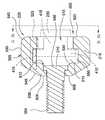
[0010]도 1은 챔버의 일 실시예의 개략적인 측단면도이다.
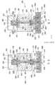
[0011]도 2는 도 1의 챔버의 확대된 부분적인 단면도이다.
[0012]도 3은 가스 분배 샤워헤드(145)에 배치된 서스펜션 피팅의 일 실시예의 확대된 단면도이다.
[0013]도 4a는 지지 부재의 일 실시예의 측면도이다.
[0014]도 4b는 도 4a의 지지 부재의 평면도이다.
[0015]도 5a는 서스펜션 피팅의 일 실시예의 측단면도이다.
[0016]도 5b는 도 5a에서 도시된 서스펜션 피팅의 상면도이다.
[0017]도 5c는 도 5b에서 도시된 서스펜션 피팅의 상면도이다.
[0018]도 6은 배킹 플레이트와 가스 분배 샤워헤드 사이에 커플링된 지지 부재의 다른 실시예의 단면도이다.
[0019]도 7은 배킹 플레이트와 가스 분배 샤워헤드 사이에 커플링된 지지 부재의 다른 실시예의 단면도이다.
[0020]도 8은 도 1의 챔버에서 활용될 수 있는 배킹 플레이트의 일 실시예의 평면도이다.
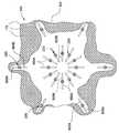
[0021]도 9는 본원에서 설명되는 실시예들에 따른 가스 분배 샤워헤드의 일 실시예의 일부의 개략적인 저면도이다.
[0022]도 10a 및 도 10b는 가스 분배 샤워헤드의 대안적인 실시예들의 개략적인 부분적인 단면도들이다.
[0023]이해를 용이하게 하기 위해, 도면들에 대해 공통인 동일한 엘리먼트들을 지정하기 위해 가능한 경우에 동일한 참조 번호들이 사용되었다. 일 실시예의 엘리먼트들 및 특징들이 추가적인 설명 없이 다른 실시예들에 유익하게 포함될 수 있는 것으로 또한 고려된다.[0009] In the manner in which the recited features of the present disclosure can be understood in detail, a more particular description of the disclosure, briefly summarized above, may be had by reference to embodiments, Are illustrated in the drawings. It should be noted, however, that the appended drawings illustrate only typical embodiments of the present disclosure and are therefore not to be considered limiting of the scope of the present disclosure, which is not intended to limit the scope of the present disclosure to other equally effective embodiments It is because.
[0010] Figure 1 is a schematic side cross-sectional view of one embodiment of a chamber.
[0011] FIG. 2 is an enlarged partial cross-sectional view of the chamber of FIG. 1.
[0012] FIG. 3 is an enlarged cross-sectional view of one embodiment of a suspension fitting disposed in a
[0013] FIG. 4A is a side view of one embodiment of a support member.
[0014] FIG. 4B is a top view of the support member of FIG. 4A.
[0015] FIG. 5A is a side cross-sectional view of one embodiment of a suspension fitting.
[0016] FIG. 5B is a top view of the suspension fitting shown in FIG. 5A.
[0017] FIG. 5C is a top view of the suspension fitting shown in FIG. 5B.
[0018] FIG. 6 is a cross-sectional view of another embodiment of a support member coupled between a backing plate and a gas distribution showerhead.
[0019] FIG. 7 is a cross-sectional view of another embodiment of a support member coupled between a backing plate and a gas distribution showerhead.
[0020] FIG. 8 is a top view of one embodiment of a backing plate that may be utilized in the chamber of FIG. 1;
[0021] FIG. 9 is a schematic bottom view of a portion of one embodiment of a gas distribution showerhead according to embodiments described herein.
[0022] Figures 10A and 10B are schematic, partial cross-sectional views of alternative embodiments of a gas distribution showerhead.
[0023] To facilitate understanding, identical reference numerals have been used, where possible, to designate identical elements that are common to the figures. It is also contemplated that the elements and features of one embodiment may be beneficially included in other embodiments without further explanation.
[0024]본 개시내용의 실시예들은 일반적으로, 프로세싱 챔버에서 가스 분배 샤워헤드를 지지하기 위한 장치 및 방법들을 제공한다. 일 실시예에서, 가스 분배 샤워헤드의 중앙과 측면들 사이에서 가스 분배 샤워헤드의 구역에 커플링된 적어도 하나의 지지 부재는 가스 분배 샤워헤드를 지지하도록 구성된다. 적어도 하나의 지지 부재는, 중력들, 고 프로세싱 온도들, 및 부압 중 하나 또는 이들의 조합에 의해 야기되는 처짐 또는 휨에 대한 저항을 가능하게 하기 위해 활용되고, 그에 의해, 가스 분배 샤워헤드에서 원하는 수평 프로파일이 유지된다. 원하는 수평 프로파일은 평평한(예컨대, 평면의) 수평 프로파일, 볼록한 수평 프로파일, 또는 오목한 수평 프로파일 중 적어도 하나일 수 있다. 원하는 수평 프로파일은, 적어도 하나의 지지 부재에 의해 제공되는 힘들에 의해 적어도 부분적으로 형성 또는 유지될 수 있다. 본원에서 사용되는 바와 같은 가스 분배 샤워헤드 또는 확산기의 수평 프로파일은 적용가능한 도면들에서 도시된 바와 같은 가스 분배 샤워헤드의 단면을 지칭한다. 본 개시내용은, 캘리포니아, 산타클라라의 어플라이드 머티어리얼스, 인코포레이트의 자회사인 AKT America, Inc.로부터 입수가능한 PECVD 장치에 관하여 아래에서 설명될 것이다. 본 개시내용이 또한, 다른 제조자들로부터 입수가능한 증착 챔버들 및 PECVD 장치를 포함하는 다른 증착 챔버들에서 적용성을 갖는다는 것이 이해될 것이다.[0024] Embodiments of the present disclosure generally provide apparatus and methods for supporting a gas distribution showerhead in a processing chamber. In one embodiment, at least one support member coupled to a region of the gas distribution showerhead between the center and the sides of the gas distribution showerhead is configured to support the gas distribution showerhead. The at least one support member is utilized to enable resistance to deflection or warping caused by gravity, high processing temperatures, and / or a combination of negative pressures, The horizontal profile is maintained. The desired horizontal profile may be at least one of a flat (e.g., planar) horizontal profile, a convex horizontal profile, or a concave horizontal profile. The desired horizontal profile can be at least partially formed or retained by the forces provided by the at least one support member. The horizontal profile of a gas distribution showerhead or diffuser as used herein refers to a cross section of a gas distribution showerhead as shown in the applicable figures. This disclosure will be described below with respect to PECVD equipment available from AKT America, Inc., a subsidiary of Applied Materials, Inc. of Santa Clara, California. It will be appreciated that the present disclosure is also applicable to other deposition chambers including PECVD apparatus and deposition chambers available from other manufacturers.
[0025]도 1은 챔버(100)의 일 실시예의 개략적인 측단면도이다. 챔버(100)는 유리, 폴리머로 제조된 대면적 기판(105) 또는 다른 적합한 기판 상에 회로를 제작하기 위한 플라즈마 강화 화학 기상 증착(PECVD) 프로세스들에 적합하다. 챔버(100)는 액정 디스플레이(LCD)들 또는 평판 디스플레이들, 솔라 셀 어레이들을 위한 광전지 디바이스들, 또는 다른 구조들의 제작에서 사용하기 위해 대면적 기판(105) 상에 구조들 및 디바이스들을 형성하도록 구성된다. 구조들은 복수의 순차적인 증착 및 마스킹 단계들을 포함할 수 있는 복수의 백 채널 에칭 반전 스태거링(back channel etch inverted staggered)(하단 게이트) 박막 트랜지스터들일 수 있다. 다른 구조들은 광전지 셀들을 위한 다이오드들을 형성하기 위해 p-n 접합들을 포함할 수 있다.[0025] FIG. 1 is a schematic side cross-sectional view of one embodiment of a
[0026]챔버(100)는 챔버 측벽(110), 하단(115), 프로세싱 동안에 대면적 기판(105)을 지지하는 기판 지지부(120), 이를테면 서셉터를 포함한다. 가스 분배 샤워헤드(145)는 기판 지지부(120) 및 대면적 기판(105)과 대향하여 위치된다. 챔버(100)는 또한, 선택적으로 개방 및 폐쇄함으로써 대면적 기판(105)의 이송 및 대면적 기판(105)에 대한 증착 프로세스들을 가능하게 하는 포트(125), 이를테면 슬릿 밸브를 갖는다. 챔버(100)는 또한, 덮개 구조(130), 배킹 플레이트(140), 및 가스 분배 샤워헤드(145)를 포함한다. 일 실시예에서, 덮개 구조(130)는 배킹 플레이트(140) 및 가스 분배 샤워헤드(145)를 지지한다. 일 실시예에서, 배킹 플레이트(140)의 내부 표면(146)과 챔버 측벽(110)의 내부 표면(147)은 가변 압력 구역(148)을 한정한다. 일 양상에서, 챔버(100)는, 가변 압력 구역(148)을 한정하는, 챔버 측벽(110), 하단(115), 및 배킹 플레이트(140)를 포함하는 바디를 포함한다. 배킹 플레이트(140)는, 배킹 플레이트(140)와 덮개 구조(130)가 서로 접촉할 수 있는 계면들에서 적합한 o-링들에 의해 배킹 플레이트(140)의 둘레가 밀봉된다. o-링들은 챔버(100)에 커플링된 진공 펌프에 의해 부압(negative pressure)이 제공되는 경우에 가변 압력 구역(148)을 밀봉할 뿐만 아니라 전기 절연을 가능하게 한다.The
[0027]도시된 실시예에서, 가스 분배 샤워헤드(145)는 하나 또는 그 초과의 중앙 지지 부재들(150)에 의해 가스 분배 샤워헤드(145)의 중앙 구역에서 배킹 플레이트(140)에 의해 지지된다. 중앙 지지 부재들(150)에 부가하여 또는 단독으로 사용될 수 있는 하나 또는 그 초과의 중간 지지 부재들 또는 중간-지지 부재(mid-support member)들이 중앙 지지 부재들(150)의 외측에 있다. 본원에서 설명되는 바와 같은, 지지 부재들에 관한 "중앙"이라는 용어는 가스 분배 샤워헤드(145) 및/또는 배킹 플레이트(140)의 기하학적 중심 주위의 구역으로서 정의될 수 있다. 마찬가지로, 본원에서 설명되는 바와 같은, 지지 부재들에 관한 "중간"이라는 용어는 가스 분배 샤워헤드(145) 및/또는 배킹 플레이트(140)의 주변 에지와 "중앙" 구역 사이의 구역으로서 정의될 수 있다.In the illustrated embodiment, the
[0028]하나 또는 그 초과의 중앙 지지 부재들(150) 및/또는 중간-지지 부재들(152)은 가스 분배 샤워헤드(145)의 수평 프로파일을 제어하도록 가스 분배 샤워헤드(145)의 지지를 가능하게 한다. 하나 또는 그 초과의 중앙 지지 부재들(150) 및/또는 중간-지지 부재들(152)은 또한, 열, 중력 및 진공 중 하나, 또는 열, 중력 및 진공의 조합으로 인해, 가스 분배 샤워헤드(145)가 늘어지거나 또는 처지는 경향을 완화하기 위해 활용될 수 있다. 가스 분배 샤워헤드(145)는 또한, 가요성 서스펜션(155)에 의해 가스 분배 샤워헤드(145)의 둘레에서 지지될 수 있다. 가요성 서스펜션(155)은 가스 분배 샤워헤드(145)의 에지들로부터 가스 분배 샤워헤드(145)를 지지하고, 가스 분배 샤워헤드(145)의 측방향 팽창 및 수축을 가능하게 하도록 적응된다.One or more of the
[0029]챔버(100)는 가스 소스 및 플라즈마 소스(165)에 커플링된 가스 유입구(160)에 커플링된다. 플라즈마 소스(165)는 직류 전력 소스, 무선 주파수(RF) 전력 소스, 또는 원격 플라즈마 소스일 수 있다. RF 전력은 챔버(100)에 유도성으로 또는 용량성으로 커플링될 수 있다. 가스 유입구(160)는 가스 소스로부터, 보어(162)를 통해, 배킹 플레이트(140)와 가스 분배 샤워헤드(145) 사이에 정의된 중간 구역(170)으로 프로세스 또는 세정 가스들을 전달한다.[0029] The
[0030]동작의 일 예에서, 챔버(100)의 내부가 진공 펌프에 의해 적합한 압력으로 펌프 다운된 동안에, 프로세스 가스들이 가스 소스로부터 전달된다. 하나 또는 그 초과의 프로세스 가스들은 가스 유입구(160)를 통해, 배킹 플레이트(140)와 가스 분배 샤워헤드(145) 사이에 정의된 중간 구역(170)으로 유동한다. 이어서, 하나 또는 그 초과의 프로세스 가스들은 중간 구역(170)으로부터, 가스 분배 샤워헤드(145)를 관통하여 형성된 복수의 개구들 또는 가스 통로들(175)을 통해, 가스 분배 샤워헤드(145) 아래의 그리고 기판 지지부(120) 위의 영역에 정의된 프로세싱 구역(180)으로 유동한다.[0030] In one example of operation, while the interior of the
[0031]대면적 기판(105)은 가스 분배 샤워헤드(145) 쪽으로 기판 지지부(120)를 이동시킴으로써 이송 위치로부터 프로세싱 구역(180)으로 상승된다. 프로세싱 구역(180)의 높이는 가스 분배 샤워헤드(145)의 하부 표면과 기판 지지부(120)의 기판 수용 표면(190) 사이의 간격에 기초한 프로세스 파라미터로서 변화될 수 있다. 기판 지지부(120)는 기판 지지부(120)에 커플링된 또는 기판 지지부(120) 내에 배치된 저항성 가열기 또는 가열 코일들과 같은 일체형 가열기에 의해 가열될 수 있다.The
[0032]챔버(100)에 커플링된 플라즈마 소스(165)에 의해 프로세싱 구역(180)에 플라즈마가 형성될 수 있다. 플라즈마 여기된 가스가 대면적 기판(105) 상에 구조들을 형성하기 위해 대면적 기판(105) 상에 증착된다. 일 실시예에서, 기판 지지부(120)는 프로세싱 구역(180) 내의 플라즈마 형성을 가능하게 하기 위해 접지 전위에 있다. 또한, 플라즈마는 열적으로 유도되는 플라즈마와 같이 다른 수단에 의해 챔버(100)에 형성될 수 있다. 본 실시예에서 플라즈마 소스(165)가 가스 유입구(160)에 커플링된 것으로 도시되어 있지만, 플라즈마 소스(165)는 가스 분배 샤워헤드(145), 또는 챔버(100)의 다른 부분들에 커플링될 수 있다.A plasma may be formed in the
[0033]가스 분배 샤워헤드(145)는 전기 전도성 재료로 제조되거나 또는 코팅되고, 가스 유입구(160) 또는 다른 연결을 통해 플라즈마 소스(165)에 커플링되며, 그에 따라, 가스 분배 샤워헤드(145)는 챔버(100) 내의 제1 전극으로서 가능할 수 있다. 가스 분배 샤워헤드(145)를 위해 선택되는 재료들은 강, 티타늄, 알루미늄, 또는 이들의 조합들을 포함할 수 있고, 표면들은 폴리싱 또는 양극산화될 수 있다. 가스 분배 샤워헤드(145)는 제1 주 표면 또는 상부 표면(185A) 및 제2 주 표면 또는 하부 표면(185B)을 포함할 수 있다. 일 실시예에서, 상부 표면(185A) 및 하부 표면(185B)은 단면이 실질적으로 평행하다. 다른 실시예에서, 상부 표면(185A)과 하부 표면(185B) 중 적어도 하나는 오목한 표면을 정의하도록 단면이 휘어질 수 있다. 다른 실시예에서, 상부 표면(185A)과 하부 표면(185B) 중 적어도 하나는 볼록한 표면을 정의하도록 휘어진다. 다른 실시예에서, 상부 표면(185A)과 하부 표면(185B) 중 적어도 하나는 평행하지 않다.The
[0034]일 실시예에서, 가스 분배 샤워헤드(145)는 접시형 또는 "스쿱형" 하부 표면(185B)을 형성하도록 둘레에서 더 두껍고 중앙에서 더 얇은 두께 또는 단면 치수를 포함할 수 있다. 이 실시예에서, 적어도 상부 표면(185A)은 실질적으로 평면이거나 또는 평평하다. 따라서, 가스 분배 샤워헤드(145)의 둘레에서의 가스 분배 샤워헤드(145)의 중앙에 비해 더 두꺼운 단면 치수는 기판 지지부(120)의 수평 프로파일에 비해 오목한 원하는 수평 프로파일을 형성한다. 다른 실시예에서, 기판 지지부(120)의 기판 수용 표면(190)은 실질적으로 평면이고, 가스 분배 샤워헤드(145)의 하부 표면(185B)은 기판 수용 표면(190)에 비해 오목하다.[0034] In one embodiment, the
[0035]도 2는 도 1의 챔버(100)의 확대된 부분적인 단면도이다. 배킹 플레이트(140)는 배킹 플레이트(140)를 통해 연장되는 복수의 개구들, 이를테면 제1 개구(205A) 및 하나 또는 그 초과의 제2 개구들(205B)을 포함한다. 일 실시예에서, 제1 개구(205A)는 가스 유입구(160)를 수용하도록 적응되고, 하나 또는 그 초과의 제2 개구들(205B)은 각각의 지지 부재(200)를 수용하도록 구성된다. 지지 부재들(200)은 도 1의 중앙 지지 부재들(150) 또는 중간-지지 부재들(152)일 수 있다. 일 실시예에서, 제1 개구(205A)는 배킹 플레이트(140)의 실질적인 기하학적 중심에 위치되지만, 제1 개구(205A)는 다른 곳에 위치될 수 있다. 커버 플레이트(135)가 활용되는 실시예들에서, 커버 플레이트(135)는 가스 유입구(160) 및 지지 부재들(200)을 수용하기 위한 스루 홀들을 포함한다. 선택적인 냉각 플레이트(미도시)가 커버 플레이트(135) 위에 위치될 수 있다. 선택적인 냉각 플레이트는 커버 플레이트(135)에 커플링될 수 있는 커버(205)의 일부를 수용하는 개구들을 가질 수 있다. 커버(205)는 하나 또는 그 초과의 파스너들(265)에 의해 커버 플레이트(135)에 체결될 수 있다.[0035] Figure 2 is an enlarged partial cross-sectional view of the
[0036]지지 부재들(200)은 서스펜션 피팅(220)과 같은 제2 지지 부재에 분리가능하게 커플링하는 제1 지지 부재(215)를 포함한다. 이 실시예에 따른 서스펜션 피팅(220)은 가스 분배 샤워헤드(145)에 서스펜션 피팅(220)의 인터페이스 바디(216)를 커플링시키는 파스너(210)를 포함한다. 파스너(210)는 각각의 가스 통로(175)에 배치될 수 있고, 그에 따라, 활용되는 가스 통로들(175)이 차단된다. 가스 분배 샤워헤드(145)의 상부 표면(185A)으로부터 하부 표면(185B)으로의 가스 유동을 가능하게 하기 위해, 대안적인 가스 통로(218)가 활용될 수 있다. 대안적인 가스 통로(218)는 가스 통로들(175)의 직경과 실질적으로 동일한 직경을 포함할 수 있다.[0036] The
[0037]지지 부재들(200)은 임의의 적합한 방식으로, 이를테면, 메이팅 베요넷(bayonet) 파스너들, 메이팅 스레딩된 부분들, 메이팅 쿼터-턴 파스너들 등에 의해, 서스펜션 피팅(220)에 분리가능하게 커플링될 수 있다. 도 2에서 도시된 실시예에서, 제1 지지 부재(215)는 제1 지지 부재(215)의 제1 단부에서 샤프트(230)를 포함하고, 제1 지지 부재(215)의 제2 단부에서 스레딩된 부분(235)을 포함한다. 스레딩된 부분(235)은 지지 너트 조립체(225)에 커플링하도록 적응된다. 지지 너트 조립체(225)는 제1 너트, 및 로킹 너트로서 활용되는 제2 너트를 포함할 수 있다. 지지 너트 조립체(225)는 스레딩된 부분(235) 및 피벗팅 구조(238)에 대하여 회전하도록 적응된다. 피벗팅 구조(238)는 볼 시트(240)와 접촉하도록 적응된다. 볼 시트(240)는 배킹 플레이트(140)의 상부 표면(245)에 형성된 오목부(242)에 배치된다. 피벗팅 구조(238) 및 볼 시트(240)는, 사용 동안에 가스 분배 샤워헤드(145)의 팽창 및 수축을 가능하게 하기 위해, 가스 분배 샤워헤드(145)가 배킹 플레이트(140)에 대하여 측방향으로(X 및/또는 Y 방향들로) 이동할 수 있게 한다.[0037] The
[0038]서스펜션 피팅(220)이 파스너(210)에 의해 가스 분배 샤워헤드(145)에 체결된 것, 샤프트(230)가 인터페이스 바디(216)에 커플링된 것, 그리고 샤프트(230)가 피벗팅 구조(238)에 커플링된 것의 조합은, 지지 너트 조립체(225)에 의해 가해지는 힘에 의해, 가스 분배 샤워헤드(145)가 배킹 플레이트(140)에 의해 서스펜딩될 수 있게 하거나 또는 수직 상방으로(Z 방향으로) 풀링될 수 있게 하는 방식으로, 지지 부재들(200)이 가스 분배 샤워헤드(145)와 메이팅할 수 있게 한다. 지지 부재들(200)의 지지 너트 조립체(225)에 의해 가스 분배 샤워헤드(145)에 가해지는 힘은 단순히, 가스 분배 샤워헤드(145) 상에 작용하는 중력에 대항할 수 있다. 대안적으로, 지지 부재들(200)은 배킹 플레이트(140)에 대하여 가스 분배 샤워헤드(145)의 수평 프로파일(즉, 가스 분배 샤워헤드(145)와 배킹 플레이트(140) 사이의 높이 또는 간격)을 조정하기 위해 활용될 수 있다.It is to be understood that the suspension fitting 220 is fastened to the
[0039]배킹 플레이트(140)는 가스 분배 샤워헤드(145)보다 단면이 비교적 더 두껍다. 가스 분배 샤워헤드(145)는, 가스 분배 샤워헤드(145) 내의 천공들 및 상대적인 두께로 인해, 배킹 플레이트(140)에 비하여 더 유연하다. 배킹 플레이트(140)는 가스 분배 샤워헤드(145)보다 더 강성이도록 구성되고, 그에 따라, 중력, 진공, 및 열과 같은 힘들에 의해 영향을 덜 받는다. 배킹 플레이트(140)는 이들 힘들로 인해 편향될 수 있지만, 가스 분배 샤워헤드(145)에 의해 겪을 수 있는 정도까지 편향되지는 않는다. 따라서, 가스 분배 샤워헤드(145)는 전술된 힘들에 의해 야기되는 약간의 변형을 겪을 수 있지만, 변형은 배킹 플레이트(140), 및 배킹 플레이트(140)와 가스 분배 샤워헤드(145) 사이에 위치된 지지 부재들(200)에 의해 효과적으로 제한된다. 따라서, 가스 분배 샤워헤드(145) 및/또는 배킹 플레이트(140)에서의 처짐 또는 변형은 지지 너트 조립체(225)의 조정에 의해 대항될 수 있고, 미리 결정될 수 있다.[0039] The
[0040]피벗팅 구조(238)의 표면에 대한 지지 너트 조립체(225)의 회전은 배킹 플레이트(140)에 대하여 샤프트(230), 서스펜션 피팅(220), 및 가스 분배 샤워헤드(145)를 상승 또는 하강시키고, 그에 따라, 가스 분배 샤워헤드(145)의 수평 프로파일을 제어한다. 일 실시예에서, 샤프트(230)의 제1 단부는 서스펜션 피팅(220)의 인터페이스 바디(216)와 제1 지지 부재(215)의 커플링 및 디커플링을 가능하게 하는 커플링 메커니즘(247)을 포함한다.The rotation of the
[0041]제2 개구들(205B) 주위의 진공 밀봉을 가능하게 하기 위해, 캡(250)이 지지 너트 조립체들(225) 각각 위에 배치된다. 캡(250)은 파스너들(255)에 의해 배킹 플레이트(140)의 상부 표면(245)에 커플링될 수 있다. o-링들과 같은 밀봉들(이 도면에서는 도시되지 않음)은 파스너들(255)의 내측에서 배킹 플레이트(140)의 상부 표면(245) 사이에 배치될 수 있다.[0041] A
[0042]도 3은 가스 분배 샤워헤드(145)에 배치된 서스펜션 피팅(220)의 일 실시예의 확대된 단면도이다. 일 실시예에서, 가스 분배 샤워헤드(145)는 가스 분배 샤워헤드(145)의 상부 표면(185A)으로부터 하부 표면(185B)으로 연장되는 제1 보어(335)를 갖는 복수의 가스 통로들(175)을 포함한다. 제1 보어(335)는 적어도 제2 보어(340)에 커플링되고, 제2 보어(340)는 제1 보어(335)에 유체적으로 커플링된다. 제2 보어(340)는 원뿔 또는 절두체의 형태로 플레어링될(flared) 수 있다. 일부 실시예들에서, 제1 보어(335)와 제2 보어(340)는 제1 보어(335) 및 제2 보어(340)의 직경보다 작은 직경을 갖는 제한 오리피스(345)에 의해 커플링된다.[0042] FIG. 3 is an enlarged cross-sectional view of one embodiment of a suspension fitting 220 disposed in a
[0043]서스펜션 피팅(220)은 제1 보어(335)의 직경보다 더 크지만 인접한 제1 보어들(335) 사이의 피치 또는 거리보다 더 작은 직경을 갖는 확장된 제2 보어(350)에 배치될 수 있다. 따라서, 벽(352)이 인접한 제1 보어(335)와 확장된 제2 보어(350) 사이에서 유지되고, 그에 따라, 파스너(210)의 스레딩된 부분(354)이 가스 분배 샤워헤드(145)에 형성된 메이팅 스레드들에 커플링될 수 있게 한다. 일 양상에서, 서스펜션 피팅(220)의 활용은 가스 분배 샤워헤드(145)에서 2개의 타입들의 가스 통로들(175), 예컨대, 서스펜션 피팅(220)의 존재에 의해 차단되는 제1 타입, 및 차단되지 않는 제2 타입을 생성한다. 따라서, 서스펜션 피팅(220)을 포함하지 않는 가스 통로들(175)은 중간 구역(170)으로부터 프로세싱 구역(180)으로 가스의 차단되지 않은 유동을 제공하는 한편, 서스펜션 피팅(220)이 내부에 배치된 가스 통로들(175)을 통하는 가스 유동은 서스펜션 피팅(220)의 존재에 의해 적어도 부분적으로 블로킹될 수 있다. 서스펜션 피팅(220)이 내부에 배치된 차단되는 가스 통로(175)를 제공하기 위해, 대안적인 가스 통로(218)가 활용된다. 대안적인 가스 통로(218)는 가스들이 중간 구역(170)으로부터 파스너(210) 아래의 제1 보어(335)로 유동할 수 있게 하기 위해 활용된다. 따라서, 가스는 서스펜션 피팅(220) 주위에서 제2 보어(350)로, 그리고 제한 오리피스(345)를 통해 프로세싱 구역(180)으로 제공될 수 있다.The suspension fitting 220 is disposed in an expanded
[0044]지지 부재(200)의 커플링 메커니즘(247)이 이 도면에서 더 명확하게 도시된다. 일 양상에서, 커플링 메커니즘(247)은, 서스펜션 피팅(220)에 형성된 각각의 슬롯(325)과 메이팅하는, 샤프트(230)의 말단 단부 상에 배치된 하나 또는 그 초과의 키들(320)을 포함하는 분리가능한 인터페이스를 제공하는 슬롯/키 디바이스를 포함한다. 커플링 메커니즘(247)은 제1 지지 부재(215)가 서스펜션 피팅(220)과 커플링 및 디커플링하도록 회전될 수 있게 하고, 이는 서스펜션 피팅(220)으로부터의 제1 지지 부재(215)의 제거를 제공한다. 아래에서 더 상세히 설명될 바와 같이, 인터페이스 바디(216)에 형성된 갭들(360)(환영으로 도시됨)은, 회전되는 경우에 샤프트(230)의 제거를 제공한다.[0044] The
[0045]도 4a는 제1 지지 부재(215)의 일 실시예의 측면도이다. 제1 지지 부재(215)는, 일 실시예에서 원형 단면을 포함하는 지지 바디(405)를 포함한다. 지지 바디(405)는 제1 단부(415)에서 지지 바디(405)로부터 반경방향 외측으로 연장되는 하나 또는 그 초과의 키 부분들(410)을 포함하고, 제1 단부(415) 반대편의 제2 단부(420) 상에 스레딩된 부분(235)을 포함한다. 제1 단부(415)의 적어도 일부는 서스펜션 피팅(220)(도 2 및 도 3) 내에 삽입되도록 사이즈가 설정되는 한편, 스레딩된 부분(235)은 지지 너트 조립체(225)(도 2)에 의해 수용되도록 적응된다. 일 실시예에서, 제1 단부(415)는 서스펜션 피팅(220) 내로의 삽입을 가능하게 하기 위해, 베벨(bevel) 또는 레디어스(radius)일 수 있는 테이퍼(taper)(425)를 포함한다. 제2 단부(420)는 또한, 지지 너트 조립체(225)를 조이고 그리고/또는 푸는 데 활용되는, 제1 지지 부재(215)의 회전 제어를 가능하게 하기 위한 툴 인터페이스(430)를 포함할 수 있다. 툴 인터페이스(430)는, 다른 타입들의 스크루 드라이브 구성들 중에서, 육각 키, 사각 키, TORX® 렌치를 위해 적응된 피메일 개구일 수 있다.[0045] FIG. 4A is a side view of one embodiment of the
[0046]도 4b는 도 4a의 제1 지지 부재(215)의 평면도이다. 키 부분들(410)은, 서스펜션 피팅(220)의 내부 채널 내에서 삽입되도록 그리고 회전하도록 사이즈가 설정된 외측 치수, 이를테면 외측 직경(435)을 포함한다.[0046] FIG. 4B is a top view of the
[0047]도 5a는 제1 지지 부재(215)의 샤프트(230)(환영으로 도시됨)가 내부에 배치된 서스펜션 피팅(220)의 일 실시예의 측단면도이다. 서스펜션 피팅(220)은 평면 부분(508)으로 테이퍼링하는 원형 지지 바디(505)(인터페이스 바디(216))를 포함한다. 외부 테이퍼(545)가 지지 바디(505)의 평면 표면(535)과 평면 부분(508) 사이에 포함될 수 있다. 지지 바디(505)는 평면 부분(508)을 통해 형성된 파스너 개구(512) 및 내부 채널(515)을 포함할 수 있는 중앙 개구(510)를 포함한다. 내부 채널(515)은 중앙 개구(510)의 직경의 일부를 한정하는 립(520) 및 중앙 개구(510)의 표면에 의해 적어도 부분적으로 포함된다. 내부 채널(515)은 측벽(550)에 의해 둘러싸일 수 있다. 일 실시예에서, 파스너(210)의 스레딩된 부분(354)은 제1 메이팅 메커니즘, 예컨대 메일 메이팅 메커니즘을 포함하는 한편, 중앙 개구(510) 및 립(520)은 제1 지지 부재(215)의 제1 단부(415)를 수용하도록 적응된 제2 메이팅 메커니즘, 이를테면 피메일 메이팅 메커니즘을 포함한다. 제1 지지 부재(215)의 제1 단부(415)는 내부 채널(515)에서 회전하도록 적응된다. 일 실시예에서, 중앙 개구(510)를 한정하는 립(520)은 제1 지지 부재(215)의 키 부분들(410)을 수용하고 그 키 부분들(410)과 메이팅하도록 적응된 슬롯형 리셉터클(555)을 포함한다.[0047] FIG. 5A is a side cross-sectional view of one embodiment of a suspension fitting 220 in which a shaft 230 (shown as illusion) of a
[0048]지지 바디(505)는 또한, 스레딩된 지지 부재(215)의 키 부분들(410)을 위한 정지부로서 기능하도록 그리고/또는 설치 후에 제1 지지 부재(215)의 회전을 제한하도록 구성된 적어도 하나의 핀(525)(도 5b에서 2개가 도시됨)을 포함한다. 핀들(525)은 도시된 바와 같이 세로로 위치될 수 있거나, 또는 핀들은 서스펜션 피팅(220)의 길이방향 축에 수직으로 지지 바디(505)에 커플링될 수 있다. 지지 바디(505)의 중앙은 샤프트(230)의 부분을 수용하도록 적응된 중앙 개구(510)를 포함한다. 이 실시예에서, 스레딩된 지지 부재(215)의 샤프트(230)는, 키 부분들(410)이 서스펜션 피팅(220)의 립(520)과 접촉하고, 배킹 플레이트(140)로부터의 가스 분배 샤워헤드(145)(둘 모두 도 1 및 도 2에서 도시됨)의 지지를 가능하게 하도록, 고정된 위치에 있다. 키 부분(410)과 유사한 적어도 하나의 피처를 포함하는 툴이 또한, 서스펜션 피팅(220)의 회전 및 조임을 가능하게 하기 위해, 그리고 가스 분배 샤워헤드(145) 상에 서스펜션 피팅(220)을 설치하는 경우에, 중앙 개구(510) 내에 삽입될 수 있다.The
[0049]일 실시예에서, 중앙 개구(510)는 내부 채널(515)로부터 파스너(210)를 향하는 원뿔형 오목부 또는 테이퍼링된 표면(530)을 포함한다. 일 실시예에서, 파스너(210)는 파스너(210)의 제1 단부에 헤드 부분(540)을 포함하고, 파스너(210)의 제2 단부에 스레딩된 부분(354)을 포함한다. 헤드 부분(540)은 스레딩된 부분(354)뿐만 아니라 개구(512)의 직경이 비하여 더 큰 치수 또는 직경을 포함한다. 일 실시예에서, 헤드 부분(540)은 제1 직경을 포함하고, 스레딩된 부분(354)은 제1 직경보다 더 작은 제2 직경을 포함한다. 평면 부분(508)과 헤드 부분(540) 사이에서 개구(512)에 숄더(536)가 형성된다. 헤드 부분(540)은, 다른 타입들의 스크루 드라이브 구성들 중에서, 육각 키, 사각 키, TORX® 렌치와 같은 툴을 위한 툴 인터페이스(미도시)를 포함할 수 있다.[0049] In one embodiment, the
[0050]도 5b는 도 5a에서 도시된 서스펜션 피팅(220)의 상면도이다. 키 부분들(410)은, 스레딩된 지지 부재(215)가 서스펜션 피팅(220)과 고정된 위치에 있도록, 립(520) 아래에 환영으로 도시되어 있다. 샤프트(230)의 대향 측들 상에 갭(360)이 도시되어, 서스펜션 피팅(220)의 테이퍼링된 표면(530)의 일부를 노출시킨다. 갭(360)은 키 부분들(410)이 중앙 개구(510) 내에 삽입되기 위한 공간을 가능하게 한다.FIG. 5B is a top view of the suspension fitting 220 shown in FIG. 5A. The
[0051]도 5c는 도 5b에서 도시된 서스펜션 피팅(220)의 상면도이다. 이 실시예에서, 샤프트(230)는 제거 위치에서 환영으로 도시된다. 샤프트(230)는 키 부분들(410)이 립(520)의 대향 측들 사이의 개구와 정렬할 수 있기 하도록 약 45°로 회전된다. 스레딩된 지지 부재(215)는, 키 부분들(410)이 도 5c에서 도시된 바와 같이 정렬됨에 따라, 서스펜션 피팅(220)의 중앙 개구(510)로부터 제거될 수 있다.[0051] FIG. 5C is a top view of the suspension fitting 220 shown in FIG. 5B. In this embodiment, the
[0052]도 6은 배킹 플레이트(140)와 가스 분배 샤워헤드(145) 사이에 커플링된 지지 부재(600)의 다른 실시예의 단면도이다. 지지 부재(600)는 도 2의 지지 부재들(200)일 수 있거나, 또는 도 1의 중앙 지지 부재들(150)과 중간-지지 부재들(152) 중 하나 또는 둘 모두일 수 있다.[0052] FIG. 6 is a cross-sectional view of another embodiment of a
[0053]지지 부재(600)는 커플링 메커니즘(247)에 커플링된 스레딩된 지지 부재(601)를 포함하고, 그 커플링 메커니즘(247)은 차례로, 가스 분배 샤워헤드(145)에 커플링된다. 지지 부재(600)는, 도 2에서 도시된 지지 부재들(200)과 유사하게, 피벗팅 구조(238) 및 볼 시트(240)를 포함한다. 피벗팅 구조(238)는 스레딩된 지지 부재(601)의 일부를 수용하는, 피벗팅 구조(238)에 형성된 중앙 개구(603)를 포함한다. 피벗팅 구조(238) 및 볼 시트(240)는 캡(250)에 의해 에워싸인다. 캡(250)은 하나 또는 그 초과의 파스너들(255)에 의해 커버 플레이트(140)에 커플링될 수 있다. o-링과 같은 밀봉(605)이 진공 밀봉을 가능하게 하기 위해 파스너들(255)과 볼 시트(240) 사이에 배치된다.The
[0054]지지 너트 조립체(225)가 스레딩된 지지 부재(601)의 스레딩된 부분(235)에 커플링된다. 이 실시예에 따른 지지 너트 조립체(225)는, 스레딩된 부분(235) 상으로 조여지도록 회전되는 경우에, 피벗팅 구조(238)의 표면과 접촉하는 적어도 제1 너트(610)를 포함한다. 일부 실시예들에서, 지지 너트 조립체(225)는 제1 너트(610)와 함께 로킹 너트로서 사용될 수 있는 제2 너트(615)를 포함한다.[0054] A
[0055]이 실시예에 따른 커플링 메커니즘(247)은, 도 3에서 설명된 커플링 메커니즘(247)과 유사하게, 파스너(210)에 의해 가스 분배 샤워헤드(145)에 커플링된 인터페이스 바디(216)를 포함한다. 그러나, 이 실시예에서, 커플링 메커니즘(247)은 도 3 내지 도 5b에서 설명되는 슬롯/키 구성 대신에, 피벗팅 구조(620)를 포함한다. 파스너(210)는 차단된 가스 통로(608)를 형성하기 위해 가스 분배 샤워헤드(145)의 가스 통로(175)에 배치될 수 있다. 가스 바이패스 홀 또는 대안적인 가스 통로(218)가 가스 분배 샤워헤드(145)의 상부 표면(185A)으로부터 하부 표면(185B)으로 가스 유동을 제공하기 위해 활용될 수 있다.The
[0056]피벗팅 구조(620)는 스레딩된 지지 부재(601)의 스레딩된 부분(235) 반대편의 스레딩된 지지 부재(601)의 단부에 형성될 수 있다. 피벗팅 구조(620)는 서스펜션 피팅(220)의 인터페이스 바디(216)에 형성된 볼 시트(625)에 적어도 부분적으로 수용될 수 있다. 부싱(630)이 피벗팅 구조(620)와 커버(635) 사이에 배치될 수 있다. 커버(635)는 스레딩된 지지 부재(601)의 직경을 수용하는 개구(640)를 포함한다. 커버(635)는 하나 또는 그 초과의 파스너들(645)에 의해 인터페이스 바디(216)에 체결될 수 있다. 따라서, 피벗팅 구조(620) 및 부싱(630)은, 가스 분배 샤워헤드(145)에 스레딩된 지지 부재(601)를 커플링시키기 위해, 인터페이스 바디(216)에 고정될 수 있다. 피벗팅 구조(620) 및 볼 시트(625)는, 사용 동안에 가스 분배 샤워헤드(145)의 팽창 및 수축을 가능하게 하기 위해, 가스 분배 샤워헤드(145)가 배킹 플레이트(140)에 대하여 측방향으로(X 및/또는 Y 방향들로) 이동할 수 있게 한다.[0056] The pivoting
[0057]도 7은 배킹 플레이트(140)와 가스 분배 샤워헤드(145) 사이에 커플링된 지지 부재(700)의 다른 실시예의 단면도이다. 지지 부재(700)는 도 2의 지지 부재들(200)일 수 있거나, 또는 도 1의 중앙 지지 부재들(150)과 미드-지지 부재들(152) 중 하나 또는 둘 모두일 수 있다.[0057] Figure 7 is a cross-sectional view of another embodiment of a
[0058]지지 부재(700)는 다음을 제외하고 도 6에서 도시된 지지 부재(600)와 유사하다. 이 실시예에 따른 인터페이스 바디(216)는 중앙 바디(710)로부터 연장되는 하나 또는 그 초과의 연장된 섹션들(705)을 포함한다. 파스너(210)가 중앙 바디(710)와 연잔된 섹션들(705) 각각 내의 각각의 개구들을 통해 배치될 수 있다. 부가적으로, 각각의 파스너(210)는 차단된 가스 통로(608)를 형성하기 위해 가스 분배 샤워헤드(145)의 각각의 가스 통로(175)에 배치될 수 있다. 적어도 하나의 대안적인 가스 통로(218)가 가스 분배 샤워헤드(145)의 상부 표면(185A)으로부터 하부 표면(185B)으로 가스 유동을 제공하기 위해 활용될 수 있다.[0058] The supporting
[0059]도 6 및 도 7에서 설명된 지지 부재(600 및 700)의 실시예들에서, 피벗팅 구조(620)는 도 3 내지 도 5b에서 설명되는 슬롯/키 구성에 의해 대체될 수 있다.[0059] In the embodiments of the
[0060]도 8은 배킹 플레이트(140)의 일 실시예의 상면 평면도이다. 이 실시예에서, 중앙 영역(800)이 배킹 플레이트(140) 상에 도시되어 있고, 중앙 지지 부재들(150)의 패턴이 중앙 영역(800) 내에 도시된다. 배킹 플레이트(140)는 또한, 중간 지지 영역(805), 및 중간 지지 영역(805) 내의 중간-지지 부재들(152)의 패턴을 포함한다. 중앙 영역(800)은, 가스 분배 샤워헤드(145)를 위한 지지 포인트로서 결정된, 배킹 플레이트(140)와 가스 분배 샤워헤드(145)의 임의의 중앙에 위치된 영역일 수 있다. 중간 지지 영역(805)은 배킹 플레이트(140)의 에지(810)와 중앙 영역(800) 사이의 영역일 수 있다. 이 도면에서 도시되지 않은 가스 분배 샤워헤드(145)는 전형적으로, 배킹 플레이트(140) 아래에 위치되고, 배킹 플레이트(140)의 치수들과 실질적으로 동일한 치수들을 갖는다. 따라서, 가스 분배 샤워헤드(145)는, 배킹 플레이트(140)에서 도시된 엘리먼트들 중 임의의 엘리먼트가 가스 분배 샤워헤드(145)와 메이팅할 수 있게 하는 대응하는 중앙 영역을 갖는다.[0060] FIG. 8 is a top plan view of one embodiment of the
[0061]이 실시예에서 8개의 중앙 지지 부재들(150)이 대칭 패턴으로 도시되어 있지만, 복수의 중앙 지지 부재들(150)이 배킹 플레이트(140)의 중앙 영역(800)에서 임의의 패턴, 수, 및 사이즈로 이루어질 수 있다. 마찬가지로, 6개의 중간-지지 부재들(152)이 중간 지지 영역(805)에 도시되어 있지만, 복수의 중간-지지 부재들(152)이 배킹 플레이트(140)의 중간 지지 영역(805)에서 임의의 패턴, 수, 및 사이즈로 이루어질 수 있다. 또한, (이 도면에서 배킹 플레이트(140) 아래에 위치될 수 있는) 가스 분배 샤워헤드(145)에 가스를 공급하기 위해 가스 유입구(610)를 수용하도록 적응된, 배킹 플레이트(140) 내의 제1 개구(205A)가 도시된다. 대안적인 가스 도입 포트(815)가 또한 도시되고, 가스 유입구(160)와 조합하여 또는 단독으로 가스 분배 샤워헤드(145)에 프로세스 가스들을 제공하기 위해 사용될 수 있다. 부가적인 가스 도입 포트들(미도시)이 또한, 배킹 플레이트(140)를 통해 가스 분배 샤워헤드(145)에 가스들을 전달하기 위해 활용될 수 있다.Although the
[0062]도 9는 가스 분배 샤워헤드(145)의 일 실시예의 부분의 개략적인 저면도이다. 가스 분배 샤워헤드(145)는 가스 분배 샤워헤드(145)의 바디(900)에서 환영으로 도시된, 복수의 외측 가스 바이패스 홀들(905A) 및 내측 가스 바이패스 홀들(905B)을 포함한다. 외측 가스 바이패스 홀들(905A) 및 내측 가스 바이패스 홀들(905B)은 도 2뿐만 아니라 다른 도면들에서 도시된 대안적인 가스 통로들(218)에 대응한다. 가스 바이패스 홀들(905A, 905B)과 교차하는 확장된 제2 보어(350)는 도 9에서 도시되지 않는다. 가스 바이패스 홀들(905A, 905B)은, 차단된 가스 통로(608)(도 6 및 도 7에서 도시됨)에 대칭적인 가스 유동을 제공하기 위해, 가스 분배 샤워헤드(145)에서 실질적으로 대칭적인 패턴으로 형성될 수 있다. 대칭적인 패턴은 도시된 패턴으로 제한되지 않는다. 외측 가스 바이패스 홀들(905A)은 내측 가스 바이패스 홀들(905B)과 함께 또는 배타적으로 활용될 수 있다. 마찬가지로, 내측 가스 바이패스 홀들(905B)은 외측 가스 바이패스 홀들(905A)과 함께 또는 배타적으로 활용될 수 있다. 외측 가스 바이패스 홀(905A) 및 내측 가스 바이패스 홀(905B)이 각각의 서스펜션 피팅(220)에 대응하여 도시되어 있지만, 서스펜션 피팅(220)당 가스 바이패스 홀들(905A, 905B)의 수는 서스펜션 피팅(220) 당 2개 미만일 수 있다. 일 실시에에서, 복수의 외측 가스 바이패스 홀들(905A)이 각각의 서스펜션 피팅(220)과 교번할 수 있다. 대안적으로 또는 부가적으로, 복수의 내측 가스 바이패스 홀들(905B)이 복수의 외측 가스 바이패스 홀들(905A) 및/또는 각각의 서스펜션 피팅(220)과 교번할 수 있다.[0062] FIG. 9 is a schematic bottom view of a portion of one embodiment of a
[0063]도 10a 및 도 10b는 각각, 가스 분배 샤워헤드(1000A 1000B)의 실시예들의 개략적인 부분적인 단면도들이다. 도 10a는 배킹 플레이트(140)의 중앙 영역(1010), 및 배킹 플레이트(140)에 비하여 오목한 수평 프로파일의 가스 분배 샤워헤드(1000A)를 도시한다. 따라서, 이 실시예에서, 가스 분배 샤워헤드(1000A)의 하부 표면(185B)은 배킹 플레이트(140)의 수평 배향에 대하여 평행하지 않거나 또는 접시형이다. 일 실시예에서, 제1 공간 갭(G')이 배킹 플레이트(140)의 내부 표면(146)과 가스 분배 샤워헤드(1000A)의 중앙 영역(1010) 내의 상부 표면(185A) 사이에 포함되는 한편, 제2 공간 갭(G'')이 배킹 플레이트(140)의 내부 표면(146)과 가스 분배 샤워헤드(1000A)의 둘레 내의 상부 표면(185A) 사이에 포함된다.[0063] Figures 10A and 10B are schematic, partial cross-sectional views of embodiments of a
[0064]제1 공간 갭(G')은 중앙 지지 부재들(150) 및/또는 중간-지지 부재들(152)(둘 모두 도 10a 및 도 10b에서 도시되지 않음) 중 하나 또는 그 초과를 조정함으로써 조정될 수 있다. 중앙 지지 부재들(150) 및/또는 중간-지지 부재들(152)의 조정은, 가스 분배 샤워헤드(1000A, 1000B)의 수평 프로파일들을 제어하기 위해, 배킹 플레이트(140)로부터 멀어지도록 가스 분배 샤워헤드(1000A, 1000B)를 푸시하거나, 또는 배킹 플레이트(140)를 향하여 가스 분배 샤워헤드(1000A, 1000B)를 풀링하기 위해 활용될 수 있다. 제1 공간 갭(G') 및 제2 공간 갭(G'')은 실질적으로 동일하게 또는 상이하게 되도록 조정될 수 있거나 또는 유지될 수 있다. 일 예에서, 제1 공간 갭(G') 및 제2 공간 갭(G'')은 실질적으로 동일하다. 다른 예에서, 제1 공간 갭(G')은 제2 공간 갭(G'')보다 더 작을 수 있다. 일 실시예에서, 가스 통로들(175)은 가스 분배 샤워헤드(1000A)의 중앙에서의 가스 통로들(175)에 비하여 가스 분배 샤워헤드(1000A)의 둘레에서 더 긴 길이를 갖는다. 일 양상에서, 가스 통로들(175) 각각의 플레어링된 보어들은 가스 분배 샤워헤드(1000A)의 중앙에서 더 긴 길이를 포함하고, 길이는 가스 분배 샤워헤드(1000A)의 중앙으로부터 가스 분배 샤워헤드(1000A)의 둘레까지 점진적으로 증가된다.[0064] The first space gap G 'may be adjusted to accommodate one or more of the
[0065]도 10b는 배킹 플레이트(140)의 중앙 영역(1010), 및 배킹 플레이트(140)에 비하여 볼록한 수평 프로파일의 가스 분배 샤워헤드(1000B)를 도시한다. 도시되어 있지 않지만, 제1 공간 갭(G') 및 제2 공간 갭(G'')이 배킹 플레이트(140)의 내부 표면(146)과 가스 분배 샤워헤드(1000B)의 상부 표면(185A) 사이에 포함된다. 제1 공간 갭(G') 및 제2 공간 갭(G'')은 도 10a를 참조하여 설명된 바와 같이 조정될 수 있거나 또는 유지될 수 있다. 일 실시예에서, 제1 공간 갭(G') 및 제2 공간 갭(G'')은 실질적으로 동일하다. 다른 예에서, 제2 공간 갭(G'')은 제1 공간 갭(G')보다 더 작을 수 있다. 일 실시예에서, 가스 통로들(175)은 가스 분배 샤워헤드(1000B)의 둘레에서의 가스 통로들(175)에 비하여 가스 분배 샤워헤드(1000B)의 중앙에서 더 긴 길이를 갖는다. 일 양상에서, 가스 통로들(175) 각각의 플레어링된 보어들은 가스 분배 샤워헤드(1000B)의 중앙에서 더 긴 길이를 포함하고, 길이는 가스 분배 샤워헤드(1000B)의 중앙으로부터 가스 분배 샤워헤드(1000B)의 둘레까지 점진적으로 감소된다.FIG. 10B shows a
[0066]기판과 가스 분배 샤워헤드 사이의 프로세싱 공간을 유지하고, 가스 분배 샤워헤드를 통하는 가스 유동에 간섭하지 않는, 가스 분배 샤워헤드를 지지하기 위한 장치 및 방법이 설명된다. 장치는, 가스 분배 샤워헤드(145)의 단면 곡률 또는 수평 프로파일의 조작을 제공하고 그리고/또는 유지하는 하나 또는 그 초과의 중앙 지지 부재들(150) 및/또는 중간-지지 부재들(152)을 포함한다. 가스 분배 샤워헤드(145)는 평면, 볼록, 또는 오목 중 하나인 수평 프로파일을 제공하기 위해 조작될 수 있다. 가스 분배 샤워헤드(145)의 수평 프로파일은 챔버에서 배킹 플레이트(140) 및/또는 기판 지지부(120)에 대하여 조정될 수 있다. 본원에서 설명되는 바와 같은 중앙 지지 부재들(150)의 실시예들은 또한, 가스 유동에 간섭하지 않고, 그에 의해, 중앙 지지 부재들(150) 및/또는 중간-지지 부재들(152)에 인접한 기판의 위치들에서의 증착을 가능하게 한다.[0066] An apparatus and method for supporting a gas distribution showerhead that maintains a processing space between a substrate and a gas distribution showerhead and that does not interfere with the gas flow through the gas distribution showerhead is described. The apparatus includes one or more
[0067]전술한 바가 본 개시내용의 실시예들에 관한 것이지만, 본 개시내용의 다른 및 추가적인 실시예들이 본 개시내용의 기본적인 범위로부터 벗어나지 않으면서 고안될 수 있고, 본 개시내용의 범위는 다음의 청구항들에 의해 결정된다.While the foregoing is directed to embodiments of the present disclosure, other and further embodiments of the present disclosure may be devised without departing from the basic scope thereof, and the scope of the present disclosure is defined by the following claims Is determined by the claims.
Claims (18)
Translated fromKorean직사각형 바디를 포함하는 가스 분배 샤워헤드 ― 상기 직사각형 바디는 4개의 측면들, 제1 주 표면 및 상기 제1 주 표면 반대편의 제2 주 표면, 및 상기 제1 주 표면과 상기 제2 주 표면 사이에서 길이 방향으로 상기 바디를 통해 형성된 복수의 가스 통로들을 가짐 ―;
상기 바디의 중앙 구역에서 상기 바디에 커플링된 복수의 중앙 지지 부재들; 및
상기 4개의 측면들 중 하나의 측면과 상기 중앙 구역 사이에서 상기 바디에 커플링된 복수의 중간 지지 부재들
을 포함하며,
상기 중앙 지지 부재들과 상기 중간 지지 부재들 중 하나 또는 둘 모두의 적어도 일부는 서스펜션 피처(suspension feature)를 포함하고, 상기 서스펜션 피처는 상기 가스 분배 샤워헤드 외부에 위치된 인터페이스 바디(interface body)를 포함하고, 상기 인터페이스 바디는 상기 복수의 가스 통로들 중 제1 가스 통로에 배치된 파스너를 수용하는 개구를 포함하는,
플라즈마를 이용하는 기판 처리에 사용되는 장치.An apparatus for use in processing a substrate using plasma,
A gas distribution showerhead comprising a rectangular body, the rectangular body having four sides, a first major surface and a second major surface opposite the first major surface and a second major surface opposite the first major surface, A plurality of gas passages formed through the body longitudinally;
A plurality of central support members coupled to the body in a central region of the body; And
A plurality of intermediate support members coupled to the body between one side of the four sides and the central region,
/ RTI >
At least a portion of the center support members and / or one or both of the intermediate support members includes a suspension feature, wherein the suspension feature includes an interface body positioned outside the gas distribution showerhead Wherein the interface body includes an opening for receiving a fastener disposed in a first one of the plurality of gas passages.
Apparatus for use in processing a substrate using plasma.
상기 복수의 가스 통로들 각각은 상기 제1 주 표면에 형성된 제1 보어(bore)를 포함하며, 상기 제1 보어는 상기 제2 주 표면에 형성된 제2 보어에 오리피스 홀(orifice hole)에 의해 유체적으로 커플링되는,
플라즈마를 이용하는 기판 처리에 사용되는 장치.The method according to claim 1,
Wherein each of the plurality of gas passages includes a first bore formed on the first major surface and wherein the first bore is formed by an orifice hole in a second bore formed in the second major surface, ≪ / RTI >
Apparatus for use in processing a substrate using plasma.
제2 가스 통로가 상기 제1 가스 통로의 길이 방향에 대하여 경사 각도로 상기 바디를 통해 형성되며, 상기 제2 가스 통로는 상기 제1 가스 통로의 상기 제1 보어와 교차하는,
플라즈마를 이용하는 기판 처리에 사용되는 장치.3. The method of claim 2,
Wherein a second gas passage is formed through the body at an oblique angle with respect to the longitudinal direction of the first gas passage and the second gas passage intersects the first bore of the first gas passage,
Apparatus for use in processing a substrate using plasma.
상기 중앙 지지 부재들과 상기 중간 지지 부재들 중 하나 또는 둘 모두의 적어도 일부는 상기 바디의 측방향 이동을 제공하는 피벗팅 구조(pivoting structure)를 포함하는,
플라즈마를 이용하는 기판 처리에 사용되는 장치.The method according to claim 1,
Wherein at least a portion of one or both of the center support members and the intermediate support members comprises a pivoting structure that provides lateral movement of the body.
Apparatus for use in processing a substrate using plasma.
상기 중앙 지지 부재들과 상기 중간 지지 부재들 중 하나 또는 둘 모두의 적어도 일부는 상기 서스펜션 피처에 커플링하는 슬롯/키(key) 디바이스를 포함하는,
플라즈마를 이용하는 기판 처리에 사용되는 장치.5. The method of claim 4,
Wherein at least a portion of the center support members and / or one or both of the intermediate support members comprises a slot / key device coupled to the suspension feature.
Apparatus for use in processing a substrate using plasma.
상기 서스펜션 피처는 상기 인터페이스 바디에 커플링된 하나 또는 그 초과의 연장된 섹션들을 포함하는,
플라즈마를 이용하는 기판 처리에 사용되는 장치.6. The method of claim 5,
Wherein the suspension feature comprises one or more extended sections coupled to the interface body,
Apparatus for use in processing a substrate using plasma.
상기 인터페이스 바디는 외부 테이퍼(taper)를 갖는 원형 바디를 포함하는,
플라즈마를 이용하는 기판 처리에 사용되는 장치.The method according to claim 1,
Wherein the interface body comprises a circular body having an outer taper,
Apparatus for use in processing a substrate using plasma.
제1 주 표면 및 상기 제1 주 표면 반대편의 제2 주 표면을 갖는 바디를 포함하는 가스 분배 샤워헤드 ― 상기 바디는 상기 제1 주 표면과 상기 제2 주 표면 사이에 형성된 복수의 가스 통로들을 갖고, 상기 복수의 가스 통로들 각각은 상기 제1 주 표면에 형성된 제1 개구를 가지며, 상기 제1 개구는 상기 제2 주 표면에 형성된 제2 개구에 제한 오리피스(restricting orifice)에 의해 유체적으로 커플링됨 ―;
상기 바디의 중앙 구역에서 상기 바디에 커플링된 복수의 중앙 지지 부재들; 및
상기 중앙 구역과 측면 사이에서 상기 바디에 커플링된 복수의 중간 지지 부재들
을 포함하며,
상기 중앙 지지 부재들과 상기 중간 지지 부재들 중 하나 또는 둘 모두의 적어도 일부는 서스펜션 피처를 포함하고, 상기 서스펜션 피처는 상기 가스 분배 샤워헤드 외부에 위치된 인터페이스 바디를 포함하고, 상기 인터페이스 바디는 상기 복수의 가스 통로들 중 제1 가스 통로에 배치된 파스너를 수용하는 개구를 포함하는,
플라즈마를 이용하는 기판 처리에 사용되는 장치.An apparatus for use in processing a substrate using plasma,
A gas distribution showerhead comprising a body having a first major surface and a second major surface opposite the first major surface, the body having a plurality of gas passages formed between the first major surface and the second major surface Wherein each of the plurality of gas passages has a first opening formed in the first major surface and the first opening is fluidically coupleable by a restricting orifice in a second opening formed in the second major surface, Ringed -;
A plurality of central support members coupled to the body in a central region of the body; And
A plurality of intermediate support members coupled to the body between the central region and the side surface
/ RTI >
Wherein at least a portion of the center support members and / or one or both of the intermediate support members comprises a suspension feature, the suspension feature comprising an interface body located outside the gas distribution showerhead, And an opening for receiving a fastener disposed in the first of the plurality of gas passages.
Apparatus for use in processing a substrate using plasma.
상기 중앙 지지 부재들과 상기 중간 지지 부재들 중 하나 또는 둘 모두의 적어도 일부는 상기 바디의 측방향 이동을 제공하는 피벗팅 구조를 포함하는,
플라즈마를 이용하는 기판 처리에 사용되는 장치.9. The method of claim 8,
Wherein at least a portion of one or both of the center support members and the intermediate support members comprises a pivoting structure that provides lateral movement of the body.
Apparatus for use in processing a substrate using plasma.
상기 중앙 지지 부재와 상기 중간 지지 부재 중 하나 또는 둘 모두는 상기 서스펜션 피처에 커플링하는 슬롯/키 디바이스를 포함하는,
플라즈마를 이용하는 기판 처리에 사용되는 장치.9. The method of claim 8,
Wherein one or both of the center support member and the intermediate support member comprise a slot / key device coupled to the suspension feature,
Apparatus for use in processing a substrate using plasma.
상기 바디는 상기 복수의 가스 통로들 중 상기 제1 가스 통로를 둘러싸는 복수의 제2 가스 통로들을 포함하며, 복수의 가스 바이패스 홀(gas by-pass hole)들 각각은 상기 복수의 가스 통로들 중 상기 가스 통로의 길이 방향에 대하여 각도를 이루어 상기 제1 주 표면으로부터 상기 바디를 통해 형성되고, 상기 가스 통로와 교차하도록 상기 바디 내에서 종단(terminating)되는,
플라즈마를 이용하는 기판 처리에 사용되는 장치.9. The method of claim 8,
Wherein the body includes a plurality of second gas passages surrounding the first of the plurality of gas passages and wherein each of the plurality of gas by- Wherein the gas passage is formed through the body at an angle to the longitudinal direction of the gas passage from the first major surface and is terminated in the body to intersect the gas passage,
Apparatus for use in processing a substrate using plasma.
상기 복수의 제2 가스 통로들 각각은 측방향으로 배향된(oriented) 보어를 포함하는,
플라즈마를 이용하는 기판 처리에 사용되는 장치.12. The method of claim 11,
Wherein each of the plurality of second gas passages comprises a laterally oriented bore.
Apparatus for use in processing a substrate using plasma.
상기 복수의 제2 가스 통로들 각각은 하나 또는 그 초과의 보어들을 포함하며, 상기 하나 또는 그 초과의 보어들 각각은, 상기 복수의 가스 통로들 중 하나 또는 그 초과의 인접한 제1 가스 통로들을 통해 적어도 부분적으로 연장되는,
플라즈마를 이용하는 기판 처리에 사용되는 장치.12. The method of claim 11,
Wherein each of the plurality of second gas passages comprises one or more bores and wherein each of the one or more bores includes a plurality of gas passages through one or more adjacent first gas passages At least partially extending,
Apparatus for use in processing a substrate using plasma.
상기 하나 또는 그 초과의 보어들 각각은 상기 제한 오리피스의 상류의 위치에서 종단되는,
플라즈마를 이용하는 기판 처리에 사용되는 장치.14. The method of claim 13,
Each of the one or more bores being terminated at a location upstream of the limiting orifice,
Apparatus for use in processing a substrate using plasma.
상기 인터페이스 바디는 외부 테이퍼를 갖는 원형 바디를 포함하는,
플라즈마를 이용하는 기판 처리에 사용되는 장치.9. The method of claim 8,
Wherein the interface body comprises a circular body having an outer taper,
Apparatus for use in processing a substrate using plasma.
측면, 및 제1 주 표면, 및 상기 제1 주 표면 반대편의 제2 주 표면을 갖는 바디를 포함하는 가스 분배 샤워헤드 ― 상기 바디는 상기 제1 주 표면과 상기 제2 주 표면 사이에 형성된 복수의 제1 가스 통로들을 갖고, 상기 복수의 가스 통로들 각각은 상기 제1 주 표면에 형성된 제1 보어를 갖는 제1 가스 통로를 포함하며, 상기 제1 보어는 상기 제2 주 표면에 형성된 제2 보어에 제한 오리피스에 의해 유체적으로 커플링됨 ―;
상기 복수의 제1 가스 통로들 중 제1 가스 통로들 중 하나를 둘러싸는 복수의 제2 가스 통로들 ― 상기 복수의 제2 가스 통로들 각각은 상기 복수의 제1 가스 통로들 중 상기 제1 가스 통로의 길이 방향에 대하여 각도를 이루어 상기 제1 주 표면으로부터 상기 바디를 통해 형성되고, 상기 제1 가스 통로와 교차하도록 상기 바디 내에서 종단됨 ―;
제1 서스펜션 피처에 의해 상기 바디의 중앙 구역에서 상기 바디에 커플링된 중앙 지지 부재; 및
제2 서스펜션 피처에 의해 상기 중앙 구역과 상기 측면 사이에서 상기 바디에 커플링된 중간 지지 부재
를 포함하며,
상기 중앙 지지 부재들과 상기 중간 지지 부재들 중 하나 또는 둘 모두의 적어도 일부는 서스펜션 피처를 포함하고, 상기 서스펜션 피처는 상기 가스 분배 샤워헤드 외부에 위치된 인터페이스 바디를 포함하고, 상기 인터페이스 바디는 상기 복수의 제1 가스 통로들 중 상기 제1 가스 통로에 배치된 파스너를 수용하는 개구를 포함하는,
플라즈마를 이용하는 기판 처리에 사용되는 장치.An apparatus for use in processing a substrate using plasma,
A gas distribution showerhead comprising a body having a side, a first major surface, and a second major surface opposite the first major surface, the body having a plurality of Wherein each of the plurality of gas passages includes a first gas passageway having a first bore formed on the first major surface, the first bore having a second bore formed on the second major surface, - fluidly coupled by a restrictive orifice to the first orifice;
A plurality of second gas passages surrounding one of the plurality of first gas passageways, each of the plurality of second gas passageways comprising a plurality of first gas passageways Formed through the body from the first major surface at an angle to the longitudinal direction of the passageway and terminating in the body to intersect the first gas passageway;
A central support member coupled to the body in a central region of the body by a first suspension feature; And
An intermediate support member coupled to the body between the central region and the side by a second suspension feature,
/ RTI >
Wherein at least a portion of the center support members and / or one or both of the intermediate support members comprises a suspension feature, the suspension feature comprising an interface body located outside the gas distribution showerhead, And an opening for receiving a fastener disposed in the first gas passage of the plurality of first gas passages.
Apparatus for use in processing a substrate using plasma.
상기 서스펜션 피처는 상기 인터페이스 바디에 커플링된 하나 또는 그 초과의 연장된 섹션들을 포함하는,
플라즈마를 이용하는 기판 처리에 사용되는 장치.17. The method of claim 16,
Wherein the suspension feature comprises one or more extended sections coupled to the interface body,
Apparatus for use in processing a substrate using plasma.
상기 인터페이스 바디는 외부 테이퍼를 갖는 원형 바디를 포함하는,
플라즈마를 이용하는 기판 처리에 사용되는 장치.17. The method of claim 16,
Wherein the interface body comprises a circular body having an outer taper,
Apparatus for use in processing a substrate using plasma.
Applications Claiming Priority (3)
| Application Number | Priority Date | Filing Date | Title |
|---|---|---|---|
| US201562222173P | 2015-09-22 | 2015-09-22 | |
| US62/222,173 | 2015-09-22 | ||
| PCT/US2016/048026WO2017052881A1 (en) | 2015-09-22 | 2016-08-22 | Showerhead support structures |
Publications (2)
| Publication Number | Publication Date |
|---|---|
| KR20180049126A KR20180049126A (en) | 2018-05-10 |
| KR101929192B1true KR101929192B1 (en) | 2018-12-14 |
Family
ID=58276788
Family Applications (1)
| Application Number | Title | Priority Date | Filing Date |
|---|---|---|---|
| KR1020187011284AActiveKR101929192B1 (en) | 2015-09-22 | 2016-08-22 | Showerhead support structures |
Country Status (5)
| Country | Link |
|---|---|
| US (1) | US9822449B2 (en) |
| JP (3) | JP2018528616A (en) |
| KR (1) | KR101929192B1 (en) |
| CN (1) | CN108028175B (en) |
| WO (1) | WO2017052881A1 (en) |
Families Citing this family (12)
| Publication number | Priority date | Publication date | Assignee | Title |
|---|---|---|---|---|
| TWI663674B (en)* | 2017-07-25 | 2019-06-21 | 漢民科技股份有限公司 | Assembly of chamber lid and ceiling for semiconductor processes and film deposition apparatus |
| US11094511B2 (en)* | 2018-11-13 | 2021-08-17 | Applied Materials, Inc. | Processing chamber with substrate edge enhancement processing |
| CN113056807B (en)* | 2018-11-30 | 2024-03-22 | 应用材料公司 | Film stack coverage improvement for three-dimensional NAND (3D NAND) applications |
| US11859284B2 (en)* | 2019-08-23 | 2024-01-02 | Taiwan Semiconductor Manufacturing Company Ltd. | Shower head structure and plasma processing apparatus using the same |
| TW202146691A (en)* | 2020-02-13 | 2021-12-16 | 荷蘭商Asm Ip私人控股有限公司 | Gas distribution assembly, shower plate assembly, and method of adjusting conductance of gas to reaction chamber |
| US20220049355A1 (en)* | 2020-08-14 | 2022-02-17 | Changxin Memory Technologies, Inc. | Spray head, chemical vapor deposition device, and working method of chemical vapor deposition device |
| KR102819060B1 (en)* | 2020-09-14 | 2025-06-11 | 주식회사 원익아이피에스 | Showerhead assembly and substrate processing apparatus having the same |
| CN114686853B (en)* | 2020-12-31 | 2023-09-01 | 拓荆科技股份有限公司 | Gas nozzle capable of controlling gas flow distribution |
| KR102760892B1 (en)* | 2021-01-29 | 2025-02-03 | 주성엔지니어링(주) | Apparatus for Processing Substrate |
| KR102371435B1 (en)* | 2021-05-03 | 2022-03-08 | 주식회사 기가레인 | Shower head |
| KR102612876B1 (en)* | 2021-12-21 | 2023-12-12 | 주식회사 테스 | Showerhead assembly |
| CN116555733B (en)* | 2023-05-17 | 2024-07-05 | 拓荆科技(上海)有限公司 | High Wen Penlin device |
Citations (2)
| Publication number | Priority date | Publication date | Assignee | Title |
|---|---|---|---|---|
| US20090007846A1 (en) | 2004-09-20 | 2009-01-08 | Ernst Keller | Diffuser gravity support |
| US20140246512A1 (en) | 2011-11-11 | 2014-09-04 | Michael DeGeorge | Apparatus and method for detecting materials |
Family Cites Families (9)
| Publication number | Priority date | Publication date | Assignee | Title |
|---|---|---|---|---|
| KR100714304B1 (en)* | 2001-03-22 | 2007-05-02 | 삼성전자주식회사 | Reaction Gas Supply Nozzle of Semiconductor Manufacturing Equipment |
| TWI287279B (en)* | 2004-09-20 | 2007-09-21 | Applied Materials Inc | Diffuser gravity support |
| CN101647090B (en)* | 2007-03-01 | 2012-08-29 | 应用材料公司 | RF shutter |
| US8152954B2 (en)* | 2007-10-12 | 2012-04-10 | Lam Research Corporation | Showerhead electrode assemblies and plasma processing chambers incorporating the same |
| DE112010003248B4 (en)* | 2009-08-10 | 2014-12-24 | Mitsubishi Electric Corporation | Plasma CVD device, plasma electrode and method for producing a semiconductor layer |
| US8721791B2 (en)* | 2010-07-28 | 2014-05-13 | Applied Materials, Inc. | Showerhead support structure for improved gas flow |
| KR20140055655A (en)* | 2012-11-01 | 2014-05-09 | 김동룡 | Shower plate assembly for improving uniformity of thin film |
| KR101518398B1 (en)* | 2013-12-06 | 2015-05-08 | 참엔지니어링(주) | Substrate process apparatus |
| US9290843B2 (en)* | 2014-02-11 | 2016-03-22 | Lam Research Corporation | Ball screw showerhead module adjuster assembly for showerhead module of semiconductor substrate processing apparatus |
- 2016
- 2016-08-22KRKR1020187011284Apatent/KR101929192B1/enactiveActive
- 2016-08-22JPJP2018512979Apatent/JP2018528616A/enactivePending
- 2016-08-22CNCN201680055227.3Apatent/CN108028175B/enactiveActive
- 2016-08-22WOPCT/US2016/048026patent/WO2017052881A1/ennot_activeCeased
- 2016-08-28USUS15/249,442patent/US9822449B2/enactiveActive
- 2019
- 2019-07-12JPJP2019129871Apatent/JP6824338B2/enactiveActive
- 2021
- 2021-01-12JPJP2021002565Apatent/JP7049488B2/enactiveActive
Patent Citations (2)
| Publication number | Priority date | Publication date | Assignee | Title |
|---|---|---|---|---|
| US20090007846A1 (en) | 2004-09-20 | 2009-01-08 | Ernst Keller | Diffuser gravity support |
| US20140246512A1 (en) | 2011-11-11 | 2014-09-04 | Michael DeGeorge | Apparatus and method for detecting materials |
Also Published As
| Publication number | Publication date |
|---|---|
| US20170081763A1 (en) | 2017-03-23 |
| JP2019208041A (en) | 2019-12-05 |
| JP2018528616A (en) | 2018-09-27 |
| CN108028175A (en) | 2018-05-11 |
| CN108028175B (en) | 2019-06-28 |
| JP7049488B2 (en) | 2022-04-06 |
| KR20180049126A (en) | 2018-05-10 |
| JP2021073699A (en) | 2021-05-13 |
| JP6824338B2 (en) | 2021-02-03 |
| US9822449B2 (en) | 2017-11-21 |
| WO2017052881A1 (en) | 2017-03-30 |
Similar Documents
| Publication | Publication Date | Title |
|---|---|---|
| KR101929192B1 (en) | Showerhead support structures | |
| US10087524B2 (en) | Showerhead support structure for improved gas flow | |
| CN1758826B (en) | Diffuser gravitational support and method for depositing a thin film on a substrate | |
| CN113166939B (en) | Gas diffuser mounting plate for reducing particle generation | |
| TWI740182B (en) | Gas diffuser support structure for reduced particle generation | |
| KR20200138902A (en) | Substrate processing apparatus | |
| TW202526079A (en) | Gas diffuser with diffuser gas hole plug for substrate processing | |
| WO2024220210A1 (en) | Non-axisymmetric gas diffuser for plasma enhanced chemical vapor deposition | |
| KR20160011397A (en) | Gas distribution apparatus | |
| KR20150067528A (en) | Showerhead structure, substrate processing apparatus, and methed for forming injection hole for showerhead |
Legal Events
| Date | Code | Title | Description |
|---|---|---|---|
| PA0105 | International application | St.27 status event code:A-0-1-A10-A15-nap-PA0105 | |
| A201 | Request for examination | ||
| A302 | Request for accelerated examination | ||
| P11-X000 | Amendment of application requested | St.27 status event code:A-2-2-P10-P11-nap-X000 | |
| P13-X000 | Application amended | St.27 status event code:A-2-2-P10-P13-nap-X000 | |
| PA0201 | Request for examination | St.27 status event code:A-1-2-D10-D11-exm-PA0201 | |
| PA0302 | Request for accelerated examination | St.27 status event code:A-1-2-D10-D17-exm-PA0302 St.27 status event code:A-1-2-D10-D16-exm-PA0302 | |
| PG1501 | Laying open of application | St.27 status event code:A-1-1-Q10-Q12-nap-PG1501 | |
| E902 | Notification of reason for refusal | ||
| PE0902 | Notice of grounds for rejection | St.27 status event code:A-1-2-D10-D21-exm-PE0902 | |
| P11-X000 | Amendment of application requested | St.27 status event code:A-2-2-P10-P11-nap-X000 | |
| P13-X000 | Application amended | St.27 status event code:A-2-2-P10-P13-nap-X000 | |
| E701 | Decision to grant or registration of patent right | ||
| PE0701 | Decision of registration | St.27 status event code:A-1-2-D10-D22-exm-PE0701 | |
| GRNT | Written decision to grant | ||
| PR0701 | Registration of establishment | St.27 status event code:A-2-4-F10-F11-exm-PR0701 | |
| PR1002 | Payment of registration fee | St.27 status event code:A-2-2-U10-U12-oth-PR1002 Fee payment year number:1 | |
| PG1601 | Publication of registration | St.27 status event code:A-4-4-Q10-Q13-nap-PG1601 | |
| PR1001 | Payment of annual fee | St.27 status event code:A-4-4-U10-U11-oth-PR1001 Fee payment year number:4 | |
| PR1001 | Payment of annual fee | St.27 status event code:A-4-4-U10-U11-oth-PR1001 Fee payment year number:5 | |
| P22-X000 | Classification modified | St.27 status event code:A-4-4-P10-P22-nap-X000 | |
| PR1001 | Payment of annual fee | St.27 status event code:A-4-4-U10-U11-oth-PR1001 Fee payment year number:6 | |
| PR1001 | Payment of annual fee | St.27 status event code:A-4-4-U10-U11-oth-PR1001 Fee payment year number:7 | |
| R17-X000 | Change to representative recorded | St.27 status event code:A-5-5-R10-R17-oth-X000 |